Movatterモバイル変換


[0]ホーム

URL:


JP2007022233A - Crawler type moving body - Google Patents

Crawler type moving body
Download PDF

Info

Publication number
JP2007022233A
JP2007022233AJP2005205146AJP2005205146AJP2007022233AJP 2007022233 AJP2007022233 AJP 2007022233AJP 2005205146 AJP2005205146 AJP 2005205146AJP 2005205146 AJP2005205146 AJP 2005205146AJP 2007022233 AJP2007022233 AJP 2007022233A
Authority
JP
Japan
Prior art keywords
crawler
traveling
wheel
moving body
traveling crawler
Prior art date
Legal status (The legal status is an assumption and is not a legal conclusion. Google has not performed a legal analysis and makes no representation as to the accuracy of the status listed.)
Pending
Application number
JP2005205146A
Other languages
Japanese (ja)
Inventor
Takeshi Ichiyanagi
健 一柳
Kenichi Nakazato
謙一 中里
Current Assignee (The listed assignees may be inaccurate. Google has not performed a legal analysis and makes no representation or warranty as to the accuracy of the list.)
Kikuchi Seisakusho Co Ltd
Original Assignee
Kikuchi Seisakusho Co Ltd
Priority date (The priority date is an assumption and is not a legal conclusion. Google has not performed a legal analysis and makes no representation as to the accuracy of the date listed.)
Filing date
Publication date
Application filed by Kikuchi Seisakusho Co LtdfiledCriticalKikuchi Seisakusho Co Ltd
Priority to JP2005205146ApriorityCriticalpatent/JP2007022233A/en
Publication of JP2007022233ApublicationCriticalpatent/JP2007022233A/en
Pendinglegal-statusCriticalCurrent

Links

Images

Landscapes

Abstract

Translated fromJapanese

【課題】 走行路上の倒木や階段状の構造物などの障害物を乗り越える機能を新たに設け、作業車両や搬器の移動手段としてさらに用途の拡大を図る。
【解決手段】 移動体フレーム10の両側に対にして、垂直方向に向けて略三角形状に配置された上部の駆動輪(201)及び下部の複数の転輪とこれら駆動輪と転輪との間に略三角形状に巻き掛けられたクローラとを有する走行クローラ20を備え、各種駆動形式により駆動するクローラ式移動体において、各走行クローラ20を上部の駆動輪201の回転軸を傾動中心として垂直方向に傾動する走行クローラ傾動装置30を備える。
【選択図】 図1
PROBLEM TO BE SOLVED: To provide a new function for overcoming obstacles such as fallen trees and stair-like structures on a traveling road, and further expands the use as a moving means for work vehicles and transporters.
SOLUTION: An upper drive wheel (201) and a plurality of lower wheels arranged in a substantially triangular shape in the vertical direction as a pair on both sides of a moving body frame 10, and the drive wheels and the wheels. In a crawler-type moving body that includes a traveling crawler 20 having a crawler wound in a substantially triangular shape between them and driven by various driving types, each traveling crawler 20 is perpendicular to the rotation axis of the upper driving wheel 201 as a tilting center. A traveling crawler tilting device 30 tilting in the direction is provided.
[Selection] Figure 1

Description

Translated fromJapanese

本発明は、作業車両や搬器の移動手段として使用するクローラ式移動体に関する。  The present invention relates to a crawler type moving body used as a moving means for a work vehicle or a transporter.

従前、本願発明者は、特許文献1により、作業車両に使用するクローラ式移動体を提案している。この特許文献1によると、クローラ式移動体(作業車両)は、移動体フレーム(機体)の四隅にそれぞれ、走行クローラ(クローラ式走行装置)を備え、自走式に構成されている。このクローラ式移動体の特徴は、各走行クローラの接地面積が広いため、安定した走行が可能になっている。また、駆動方式は4WD(4輪駆動形式)が採用されているため、作業箇所の周辺の路面状態によってスリップした走行クローラがあっても、走行に不都合を生じる虞がない。さらに、ステアリングに4WS(4輪操舵形式)が採用されており、前後輪の操舵方向を逆に制御することにより作業車両の回転半径を極めて小さくして、作業範囲を小さくすることができる。
特開2000−160509公報
Conventionally, the inventor of the present application has proposed a crawler-type moving body used in a work vehicle according toPatent Document 1. According toPatent Document 1, a crawler type moving body (work vehicle) includes a traveling crawler (crawler type traveling device) at each of the four corners of a moving body frame (airframe), and is configured to be self-propelled. A feature of this crawler type moving body is that stable traveling is possible because the ground contact area of each traveling crawler is large. In addition, since 4WD (four-wheel drive type) is adopted as the driving method, there is no risk of inconvenience in traveling even if there is a traveling crawler that slips due to the road surface condition around the work site. Furthermore, 4WS (four-wheel steering type) is adopted for steering, and the working radius can be made extremely small by controlling the steering direction of the front and rear wheels in reverse to make the rotational radius of the work vehicle extremely small.
JP 2000-160509 A

しかしながら、先に提案したクローラ式移動体では、4つの走行クローラと、その4輪駆動形式及び4輪操舵形式とにより、あらゆる地形に対応した走行性能を持たせているものの、その走行路上に倒木や階段状の構造物などの障害物があった場合に、この障害物を乗り越える機能がなく、このような条件付きのフィールドに対応できないという問題がある。  However, in the previously proposed crawler type moving body, the four traveling crawlers and the four-wheel drive type and the four-wheel steering type provide the traveling performance corresponding to all terrain, but fallen trees on the traveling path. When there is an obstacle such as a stepped structure or a staircase structure, there is a problem that there is no function for overcoming the obstacle and it is impossible to cope with such a conditional field.

本発明は、先に提案したクローラ式移動体を改良するもので、このクローラ式移動体において、走行路上の倒木や階段状の構造物などの障害物を乗り越える機能を新たに設け、作業車両や搬器の移動手段としてさらに用途の拡大を図ることを目的とする。  The present invention improves the previously proposed crawler type moving body, and in this crawler type moving body, a function for overcoming obstacles such as fallen trees and staircase structures on a traveling road is newly provided, and a work vehicle, The purpose is to further expand the use as a means for moving the transporter.

上記目的を達成するために、本発明のクローラ式移動体は、移動体フレームの両側に対にして、垂直方向に向けて略三角形状に配置された上部の駆動輪及び下部の複数の転輪とこれら駆動輪と転輪との間に略三角形状に巻き掛けられたクローラとを有する走行クローラを備え、各種駆動形式により駆動するクローラ式移動体において、前記各走行クローラを前記上部の駆動輪の回転軸を傾動中心として垂直方向に傾動する走行クローラ傾動装置を備えたことを要旨とする。  In order to achieve the above object, the crawler type moving body of the present invention has an upper driving wheel and a plurality of lower rolling wheels arranged in a substantially triangular shape in the vertical direction on both sides of the moving body frame. And a crawler type moving body that is driven by various types of driving, and each of the driving crawlers is connected to the upper driving wheel. A traveling crawler tilting device that tilts in the vertical direction with the rotation axis of the shaft as the tilting center is provided.

また、本発明は次のように具体化される。第1に、移動体フレームに各走行クローラの上部を跨ぐ支持部材を備え、前記各支持部材に前記各走行クローラは駆動輪の回転軸と同軸上で傾動可能に支持され、走行クローラ傾動装置は、前記走行クローラごとにその側方に配置され、一端を前記駆動輪の上方で前記支持部材に垂直方向に傾動可能に軸支され、他端を最前方位置の転輪の回転軸と同軸上に垂直方向に傾動可能に軸支されたシリンダと、その駆動装置とにより構成される。第2に、各走行クローラは複数の転輪が水平方向に一列に配列された前輪、中間輪、及び後輪からなり、駆動輪と前記前輪との間隔を前記駆動輪と前記後輪との間隔よりも長くした配置構成を採る。第3に、各走行クローラは各別に駆動される形式に構成される。第4に、各走行クローラは各別に操舵される形式に構成される。第5に、各走行クローラは最大操舵角度90度に構成される。第6に、各走行クローラは静油圧式無段階変速装置(HSТ)により無段階変速方式に構成される。  In addition, the present invention is embodied as follows. First, the moving body frame is provided with a support member straddling the upper part of each traveling crawler, and each traveling crawler is supported on each of the supporting members so as to be tiltable coaxially with the rotation shaft of the drive wheel, and the traveling crawler tilting device is Each of the traveling crawlers is disposed on the side of the traveling crawler, and one end of the traveling crawler is pivotally supported so as to be vertically tiltable to the support member above the driving wheel, and the other end is coaxial with the rotating shaft of the frontmost wheel. The cylinder is pivotally supported so as to be tiltable in the vertical direction, and a driving device thereof. Second, each traveling crawler includes a front wheel, an intermediate wheel, and a rear wheel in which a plurality of wheels are arranged in a row in the horizontal direction, and the distance between the driving wheel and the front wheel is set between the driving wheel and the rear wheel. The arrangement configuration is longer than the interval. Third, each traveling crawler is configured to be driven separately. Fourth, each traveling crawler is configured to be steered separately. Fifth, each traveling crawler is configured with a maximum steering angle of 90 degrees. Sixth, each traveling crawler is configured in a continuously variable transmission system by a hydrostatic continuously variable transmission (HSТ).

本発明のクローラ式移動体は、上記各構成により、走行路上に倒木や階段状の構造物などの障害物があってもそれを乗り越えることができ、作業車両や搬器の移動手段としてさらに用途の拡大を図ることができる。  The crawler type moving body of the present invention can be used even if there is an obstacle such as a fallen tree or a stair-like structure on the traveling road, and can be used as a moving means for a work vehicle or a carrier. Can be expanded.

以下、本発明の一実施の形態について図を用いて説明する。図1において、クローラ式移動体1は、移動体フレーム10の前後に、(左右)両側に対にして、走行クローラ20を備え、これら走行クローラ20が各種駆動形式により駆動される自走式の構成になっている。  Hereinafter, an embodiment of the present invention will be described with reference to the drawings. In FIG. 1, a crawlertype moving body 1 is provided with a travelingcrawler 20 in pairs on both sides (left and right) before and after a movingbody frame 10, and these travelingcrawlers 20 are driven by various drive types. It is configured.

移動体フレーム10上には、内燃機関と、走行用トランスミッションとして、ポンプとモータを組み合わせた静油圧式無段階変速装置(Hydro Static Transmission)が搭載される。図1に示すように、移動体フレーム10にはエンジン11、このエンジン11により駆動される走行駆動用ポンプ12およびアクチュエータ駆動用ポンプ13が搭載されるとともに、補機14やウェイト15がエンジン11と均衡すべく、振分けて設置される。図2に示すように、エンジン11によって、Vベルト等を介して前部側の走行クローラ20F用の走行駆動用ポンプ12F、後部側の走行クローラ20R用の走行駆動用ポンプ12R、油吸上ポンプ16およびアクチュエータ用ポンプ17が回転駆動される。これらのポンプは二連斜板ポンプと二連ギヤポンプとを併置したもの等が採用され、斜板の傾斜角度の選定によって送油量すなわち走行速度の無段階微調整が可能である。油吸上ポンプ16により油タンクТから吸い上げられた油は、前部側の走行クローラ20F及び後部側の走行クローラ20Rの前進用あるいは後進用の逆止弁18Fあるいは18Rおよび前進用あるいは後進用のリリーフ弁19Fあるいは19Rを通じて調圧されて、前部側の走行クローラ20F用の走行駆動用ポンプ12F、後部側の走行クローラ20R用の走行駆動用ポンプ12Rにより、各走行クローラ20F、20Rにおける各駆動用油圧モータ21F、21Rがそれぞれ回転駆動される。このようにして各走行クローラ20F、20Rの駆動は、あらゆる速度に対応して最大トルクを発生する回転数を維持した無段変速を可能にする。このように走行クローラ20F、20Rの駆動がHSTによりなされるように構成されるので、このクローラ式移動体1が作業車両として利用される場合に、あらゆる速度に適応させて路面作業を走行速度と作業機械の挙動に整合させて最大トルクを発生させる回転数を維持することができる。  On the movingbody frame 10, a hydrostatic continuously variable transmission (Hydro Static Transmission) combining a pump and a motor is mounted as an internal combustion engine and a traveling transmission. As shown in FIG. 1, the movingbody frame 10 is equipped with an engine 11, atravel drive pump 12 driven by the engine 11, and anactuator drive pump 13, and anauxiliary machine 14 and aweight 15 are connected to the engine 11. In order to balance, it will be distributed. As shown in FIG. 2, a driving drive pump 12F for the travelingcrawler 20F on the front side, atraveling drive pump 12R for the travelingcrawler 20R on the rear side, and an oil suction pump are driven by the engine 11 via a V belt or the like. 16 and the actuator pump 17 are rotationally driven. These pumps employ a double swash plate pump and a double gear pump, etc., and the oil feed amount, that is, the traveling speed can be finely adjusted steplessly by selecting the inclination angle of the swash plate. The oil sucked up from the oil tank Т by theoil suction pump 16 is used for the forward orreverse check valve 18F or 18R of thefront traveling crawler 20F and therear traveling crawler 20R and the forward or reverse traveling. Each drive in each travelingcrawler 20F, 20R is regulated by arelief valve 19F or 19R and is driven by a traveling drive pump 12F for the travelingcrawler 20F on the front side and a travelingdrive pump 12R for the travelingcrawler 20R on the rear side. Thehydraulic motors 21F and 21R are rotationally driven. In this way, the driving of each of the traveling crawlers 20F and 20R enables a continuously variable transmission that maintains a rotational speed that generates a maximum torque corresponding to any speed. As described above, the driving crawlers 20F and 20R are configured to be driven by the HST. Therefore, when the crawlertype moving body 1 is used as a work vehicle, the road surface work can be adapted to all speeds as the traveling speed. It is possible to maintain the rotation speed that generates the maximum torque in conformity with the behavior of the work machine.

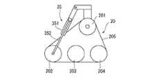
4つの走行クローラ20F、20Rはそれぞれ、図3に示すように、クローラフレーム22上に上部の駆動輪201及び下部の複数の転輪202、203、204が垂直方向に向けて略三角形状に配置され、これら駆動輪201と転輪202、203、204との間に無端状のゴムクローラ205が略三角形状に巻き掛けられて組み立てられる。この場合、特に、複数の転輪202〜204が水平方向に一列に配列された前輪202、中間輪203、及び後輪204からなり、駆動輪201と前輪202との間隔を駆動輪201と後輪204との間隔よりも長くした配置構成で、ゴムクローラ205の接地面が前輪201方向に長く延ばし出される。このゴムクローラ205を装備した走行クローラ20で設置面積を広くして、優れた安定性を発揮することができる。  As shown in FIG. 3, each of the four travelingcrawlers 20F and 20R has anupper driving wheel 201 and a plurality oflower rolling wheels 202, 203, and 204 arranged in a substantially triangular shape on thecrawler frame 22 in the vertical direction. Then, anendless rubber crawler 205 is wound around thedrive wheel 201 and therollers 202, 203, 204 in a substantially triangular shape and assembled. In this case, in particular, a plurality of rollingwheels 202 to 204 are composed of afront wheel 202, anintermediate wheel 203, and arear wheel 204 arranged in a line in the horizontal direction. The ground contact surface of therubber crawler 205 is extended in the direction of thefront wheel 201 with an arrangement configuration that is longer than the distance from thewheel 204. The travelingcrawler 20 equipped with therubber crawler 205 can widen the installation area and exhibit excellent stability.

駆動方式は各走行クローラ20が各別に駆動される4WD(4輪駆動形式)が採用され、ステアリングは各走行クローラ20が各別に操舵される4WS(4輪操舵形式)が採用される。図1及び図4に示すように、各走行クローラ20は、移動体フレーム10の前部及び後部(図示省略)の前後に垂設された一対の支持ブラケット23、23間に移動体フレーム10の中心前後方向に延びる走行クローラフレーム支軸24に軸支された走行クローラフレーム25により、走行クローラフレーム支軸24の周りで揺動可能に構成される。走行クローラフレーム25の左右両端部にそれぞれキングピン26が鉛直方向に設けられ、キングピン26を介して、ナックルアーム27が軸支される。これらのナックルアーム27にそれぞれ各別に駆動される駆動用油圧モータ21F、21Rが設置され、これらの駆動用油圧モータ21F、21Rにそれぞれ、図2に示すように、各走行クローラ20の駆動輪201が減速装置28F、28Rを介して装着される。このようにして移動体フレーム10の前部及び後部の左右両側に各走行クローラ20F、20Rが、各別に回転駆動力が伝達される4輪駆動形式に構成される。また、図4に示すように、左右のナックルアーム27にはそれぞれ操舵ロッド29の端部が軸支され、これらの他端部同士は連携されて同期操作される。この操舵29の直線的な移動によって、ナックルアーム27すなわち駆動用油圧モータ21F、21Rに装着された走行クローラ20F、20Rがキングピン26を中心として矢印の方向に操舵される。図5に、この操舵機構によって、各走行クローラ20F、20Rを操舵する様子を示している。ここで、直線走行時の各走行クローラ20F、20Rを実線で示し、左前方(図面右下)へ操舵した状態を1点鎖線で示し、操舵ロッド29を移動体フレーム10外方へ移動させて各走行クローラ20F、20Rを右前方(図面左下)へ移動し、ついには走行クローラ20の操舵角度を最大90°まで操舵した状態を2点鎖線で示している。このようにして移動体フレーム10の前部及び後部の左右両側に各走行クローラ20F、20Rは4輪操舵形式に構成される。この4WSにより、前部側の各走行クローラ20Fと後部側の各走行クローラ20Rとを同方向、同角度に操舵することによって、移動体フレーム10の向きを変えずに斜め前(又は後)への移動が可能となる。さらに前部側及び後部側の各走行クローラ20F、20Rが共に右方向に90度、左方向に30度の操舵範囲を持つので、移動体フレーム10を真横移動させることも可能である。この4輪操舵形式により、作業性の向上、作業エリアの縮小、移動時間の短縮などの利点がある。  The driving method is 4WD (four-wheel drive type) in which each travelingcrawler 20 is driven individually, and the steering is a 4WS (four-wheel steering type) in which each travelingcrawler 20 is steered separately. As shown in FIG. 1 and FIG. 4, each travelingcrawler 20 includes a movingframe 10 between a pair ofsupport brackets 23, 23 that are suspended before and after a front portion and a rear portion (not shown) of the movingframe 10. A travelingcrawler frame 25 that is supported by a traveling crawlerframe support shaft 24 that extends in the center front-rear direction is configured to be swingable around the traveling crawlerframe support shaft 24. King pins 26 are provided in the vertical direction at both left and right ends of the travelingcrawler frame 25, and aknuckle arm 27 is pivotally supported via the king pins 26. Theknuckle arms 27 are respectively provided with drivinghydraulic motors 21F and 21R that are driven individually. The drivinghydraulic motors 21F and 21R are respectively provided with drivingwheels 201 of the travelingcrawlers 20 as shown in FIG. Are mounted viaspeed reducers 28F and 28R. In this way, the traveling crawlers 20F and 20R are configured in a four-wheel drive type in which the rotational driving force is transmitted separately to the left and right sides of the front and rear portions of the movingbody frame 10. As shown in FIG. 4, the left andright knuckle arms 27 are pivotally supported at the ends of the steeringrod 29, and the other ends are linked and operated synchronously. By the linear movement of thesteering 29, the traveling crawlers 20F and 20R attached to theknuckle arm 27, that is, the drivinghydraulic motors 21F and 21R, are steered in the direction of the arrow about theking pin 26. FIG. 5 shows how the traveling crawlers 20F and 20R are steered by this steering mechanism. Here, the traveling crawlers 20F and 20R at the time of linear traveling are indicated by solid lines, the state of steering to the left front (lower right in the drawing) is indicated by a one-dot chain line, and the steeringrod 29 is moved outward of the movingbody frame 10. A state in which the traveling crawlers 20F and 20R are moved right front (lower left in the drawing) and the steering angle of the travelingcrawler 20 is finally steered to a maximum of 90 ° is indicated by a two-dot chain line. In this way, the traveling crawlers 20F and 20R are configured in a four-wheel steering type on the left and right sides of the front and rear portions of the movingbody frame 10. By this 4WS, each travelingcrawler 20F on the front side and each travelingcrawler 20R on the rear side are steered in the same direction and at the same angle, thereby moving forward (or rearward) without changing the orientation of the movingbody frame 10. Can be moved. Further, since the traveling crawlers 20F and 20R on the front side and the rear side both have a steering range of 90 degrees in the right direction and 30 degrees in the left direction, it is possible to move the movingbody frame 10 laterally. This four-wheel steering system has advantages such as improved workability, reduced work area, and reduced travel time.

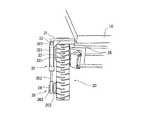
各走行クローラ20にはまた、段差突破機構を備える。これは各走行クローラ20が各別に、上部の駆動輪201の回転軸を傾動中心として垂直方向に傾動される走行クローラ傾動装置30として具体化される。この場合、図6に示すように、移動体フレーム10に、各キングピン26の頂部から各走行クローラ20の上部を跨ぎ、上部の駆動輪201の回転軸まで延びる略逆L字形の支持ブラケット31が取り付けられ、これらの支持ブラケット31に支軸32(図3参照)を介して、各走行クローラ20が駆動輪201の回転軸と同軸上で垂直方向に傾動可能に支持される。これに併せて、各走行クローラ20の駆動輪201の上方で各支持ブラケット31の上部角部付近に軸受部材33が取り付けられ、各走行クローラ20の最前方位置の転輪(前輪)202の回転軸と同軸上に軸受部材34が取り付けられる。走行クローラ傾動装置30は、走行クローラ20ごとにその外側方に配置される油圧シリンダ35と、その駆動装置とにより構成される。各油圧シリンダ35はシリンダ351側一端の取付部361を支持ブラケット31上部の軸受部材33に軸を介して垂直方向に傾動可能に軸支され、ピストン352が伸縮量の中立点まで伸ばされてピストン352側他端の取付部362を前輪202の軸受部材34に軸を介して垂直方向に傾動可能に軸支される。これらの油圧シリンダ35は駆動装置の油圧ポンプ13に接続される。  Eachtraveling crawler 20 is also provided with a step breakthrough mechanism. This is embodied as a traveling crawler tiltingdevice 30 in which each travelingcrawler 20 is tilted in the vertical direction about the rotational axis of theupper drive wheel 201 as a tilting center. In this case, as shown in FIG. 6, a substantially inverted L-shapedsupport bracket 31 that extends from the top of eachking pin 26 to the top of each travelingcrawler 20 and extends to the rotation shaft of theupper drive wheel 201 is provided on the movingbody frame 10. The travel crawlers 20 are supported on thesesupport brackets 31 so as to be tiltable in the vertical direction on the same axis as the rotation shaft of thedrive wheels 201 via the support shafts 32 (see FIG. 3). At the same time, a bearingmember 33 is mounted near the upper corner of eachsupport bracket 31 above thedrive wheel 201 of each travelingcrawler 20, and the rotation of the wheel (front wheel) 202 at the foremost position of each travelingcrawler 20 is performed. A bearing member 34 is mounted coaxially with the shaft. The travelingcrawler tilting device 30 includes ahydraulic cylinder 35 disposed on the outer side of each travelingcrawler 20 and a driving device thereof. Eachhydraulic cylinder 35 is pivotally supported by a mountingmember 361 at one end on thecylinder 351 side so as to be able to tilt in the vertical direction via a shaft to a bearingmember 33 above thesupport bracket 31, and thepiston 352 is extended to the neutral point of the expansion / contraction amount. The mountingportion 362 at the other end on the 352 side is pivotally supported by the bearing member 34 of thefront wheel 202 so as to be tiltable in the vertical direction via the shaft. Thesehydraulic cylinders 35 are connected to thehydraulic pump 13 of the drive unit.

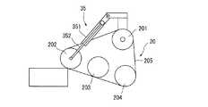
この段差突破機構は油圧シリンダ35で走行クローラ20を持ち上げることで障害物を乗り越える仕組みであり、段差前で油圧シリンダ35のピストン352を中立点(図7)から収縮することにより、走行クローラ20の設置面を水平な状態から、図8に示すように、最前方の転輪(前輪)202を上方に傾動する動き(走行クローラ20の先端を上げる動作)、段差の上に走行クローラ20を乗せてから、油圧シリンダ35のピストン352を少し伸長して前輪202を段差に押し付ける動き(走行クローラ20の乗上踏み込み動作)、段差上でピストン352をさらに中立点まで伸長して、図9に示すように、走行クローラ20の設置面を水平方向に向けて走行クローラ20の姿勢を保持する動き(走行クローラ20の姿勢保持動作)、また、段差から下方へピストン352を中立点からまたさらに伸長して、図10に示すように、前輪202を下方に傾動する動き、すなわち前輪202を段差から下ろす動き(走行クローラ20の先端を下げる動作)、そしてこの下ろす動きからピストン352を伸縮して前輪202の着地時の衝撃を緩和する動き(走行クローラ20の衝撃緩和動作)又は前輪202を着地面に押し付ける動き(走行クローラの着地踏み込み動作)、段差を乗り越えた後、油圧シリンダ35のピストン352を中立点に収縮することにより、前輪202を上方に傾動し、走行クローラ20の設置面を通常の水平な状態に戻す動き(走行クローラ20の通常姿勢保持動作)を、障害物を乗り越える基本的な動きとして備える。これらの基本的な動きと走行クローラ20の持つ推進力(HSTの制御による前進又は後退と停止)とを選択的に組み合わせた制御方式によって、走行路上の倒木や階段状の構造物を乗り越え、また、斜面を走行する。  This step breaking mechanism is a mechanism that climbs over the obstacle by lifting the travelingcrawler 20 with thehydraulic cylinder 35. By retracting thepiston 352 of thehydraulic cylinder 35 from the neutral point (FIG. 7) before the step, the travelingcrawler 20 As shown in FIG. 8, the front surface of the wheel (front wheel) 202 is tilted upward (operation for raising the tip of the traveling crawler 20), and the travelingcrawler 20 is placed on the step. After that, thepiston 352 of thehydraulic cylinder 35 is slightly extended to push thefront wheel 202 against the step (stepping on the traveling crawler 20), and thepiston 352 is further extended to the neutral point on the step, as shown in FIG. As described above, the movement of holding the posture of the travelingcrawler 20 with the installation surface of the travelingcrawler 20 oriented in the horizontal direction (the posture maintaining operation of the traveling crawler 20) Further, thepiston 352 is further extended from the neutral point downward from the step, and as shown in FIG. 10, thefront wheel 202 is tilted downward, that is, thefront wheel 202 is lowered from the step (the tip of the travelingcrawler 20 is lowered). Operation), and a movement to reduce the impact when thefront wheel 202 is landed by expanding and contracting thepiston 352 from this downward movement (impact mitigating operation of the traveling crawler 20) or a movement of pressing thefront wheel 202 against the landing surface (landing operation of the traveling crawler) ) After overcoming the step, thepiston 352 of thehydraulic cylinder 35 is contracted to a neutral point, thereby tilting thefront wheel 202 upward and returning the installation surface of thetravel crawler 20 to a normal horizontal state (travel crawler 20). Normal posture holding operation) is provided as a basic movement over an obstacle. By using a control system that selectively combines these basic movements and the propulsive force of the traveling crawler 20 (advanced or retracted and stopped by the HST control), the vehicle overcomes fallen trees and stair-like structures on the traveling road, and Travel on the slope.

倒木を乗り越える場合、まず、倒木に接近したときに、前部側の各走行クローラ20Fの先端を上げる動作により、前部側の各走行クローラ20Fの先端を持ち上げる。このとき、後部側の各走行クローラ20Rを通常の姿勢に維持する。前部側の各走行クローラ20Fを倒木の上に乗せたときに、各走行クローラ20Fの乗上踏み込み動作により、各走行クローラ20Fを踏み込みながら、倒木の上に乗り上げる。このとき、後部側の各走行クローラ20Rを引き続き通常の姿勢に維持する。倒木上で前部側の各走行クローラ20Fの姿勢保持動作により、各走行クローラ20Fの姿勢を保持してから、各走行クローラ20Fの先端を下げる動作により、各走行クローラ20Fの先端を倒木から下ろしていく。そして、前部側の各走行クローラ20Fの衝撃緩和動作により、各走行クローラ20Fの着地時の衝撃を緩和する。倒木を乗り越えたところで、前部側の各走行クローラ20Fの通常姿勢保持動作により、各走行クローラ20Fの設置面を通常の水平な状態に戻す。このとき、後部側の各走行クローラ20Rの先端を上げる動作により、各走行クローラ20Rの先端を持ち上げて、同様の動きを繰り返す。この倒木を乗り越える動作では、特に、走行クローラ20を倒木の上に乗せたときに走行クローラ20の倒木を踏み込む動作により、倒木に対して加重を垂直に加えることができ、これが倒木を押える作用となって、走行クローラ20が倒木を回転させることなく確実に乗り越えることができる。  When climbing over a fallen tree, first, when approaching the fallen tree, the tip of each travelingcrawler 20F on the front side is lifted by raising the tip of each travelingcrawler 20F on the front side. At this time, each travelingcrawler 20R on the rear side is maintained in a normal posture. When each travelingcrawler 20F on the front side is placed on a fallen tree, the travelingcrawler 20F rides on the fallen tree while stepping on each travelingcrawler 20F by the stepping-on operation of each travelingcrawler 20F. At this time, each travelingcrawler 20R on the rear side is continuously maintained in a normal posture. The posture of each travelingcrawler 20F is held by the posture maintaining operation of each travelingcrawler 20F on the fallen tree, and then the tip of each travelingcrawler 20F is lowered by the operation of lowering the distal end of each travelingcrawler 20F. To go. And the impact at the time of landing of each travelingcrawler 20F is relieved by the impact relaxation operation of each travelingcrawler 20F on the front side. After overcoming the fallen tree, the normal posture maintaining operation of each travelingcrawler 20F on the front side returns the installation surface of each travelingcrawler 20F to a normal horizontal state. At this time, the tip of each travelingcrawler 20R is raised by the operation of raising the leading end of each travelingcrawler 20R, and the same movement is repeated. In the operation of overcoming the fallen tree, in particular, when thetravel crawler 20 is placed on the fallen tree, the action of stepping on the fallen tree of thetravel crawler 20 can apply a weight to the fallen tree vertically. Thus, the travelingcrawler 20 can reliably get over without rotating the fallen tree.

階段を昇降する場合、まず、階段に接近したときに、前部側の各走行クローラ20Fの先端を上げる動作により、前部側の各走行クローラ20Fの先端を持ち上げる。このとき、後部側の各走行クローラ20Rを通常の姿勢に維持する。前部側の各走行クローラ20Fを段差の上に乗せたときに、各走行クローラ20Fの乗上踏み込み動作により、各走行クローラ20Fを踏み込み、走行クローラ20を階段の段差に合わせて押し付けながら、段差を登る。このとき、後部側の各走行クローラ20Rを引き続き通常の姿勢に維持する。前部側の各走行クローラ20Fが階段を登り終えた後、前部側の各走行クローラ20Fの姿勢保持動作により、各走行クローラ20Fの姿勢を保持してから、後部側の各走行クローラ20Rの先端を持ち上げて、同様の動きを繰り返す。このようにして全走行クローラ20F、20Rが階段を登り終える。階段を降りるときは、前部側の各走行クローラ20Fの先端を下げる動作により、各走行クローラ20Fの先端を1段ずつ下ろしていく。この場合、階段を1段降りるごとに、前部側の各走行クローラ20Fの衝撃緩和動作により各走行クローラ20Fの着地時の衝撃を緩和し、さらに各走行クローラ20Fの通常姿勢保持動作により、各走行クローラ20Fの設置面を通常の水平な状態に戻す。続いて、後部側の各走行クローラ20Rを同様にして階段から降ろす。この階段を昇降する動作では、階段を登る場合、走行クローラ20を階段の段差に合わせて押し付けるので、走行クローラ20が階段を滑ることなく、円滑に登ることができる。また、階段を降りる場合、走行クローラ20の衝撃緩和動作により各走行クローラ20の着地時の衝撃を緩和するので、段差を降りる際の衝撃による回転軸への負荷を避けることができ、また、走行クローラ20の通常姿勢保持動作により、走行クローラ20の設置面を通常の水平な状態に戻すので、走行クローラ20が階段から滑り落ちるのを防止することができる。  When ascending / descending the stairs, first, when approaching the stairs, the tips of the traveling crawlers 20F on the front side are lifted by raising the tips of the traveling crawlers 20F on the front side. At this time, each travelingcrawler 20R on the rear side is maintained in a normal posture. When each travelingcrawler 20F on the front side is placed on the step, each travelingcrawler 20F is stepped on by the climbing stepping operation of each travelingcrawler 20F, and the travelingcrawler 20 is pressed in accordance with the step of the stairs. Climb. At this time, each travelingcrawler 20R on the rear side is continuously maintained in a normal posture. After eachfront crawler 20F has finished climbing the stairs, the posture of each travelingcrawler 20F is maintained by the posture holding operation of eachfront crawler 20F, and then each travelingcrawler 20R on the rear side is maintained. Lift the tip and repeat the same movement. In this way, all the traveling crawlers 20F and 20R finish climbing the stairs. When going down the stairs, the leading end of each travelingcrawler 20F is lowered step by step by the operation of lowering the leading end of each travelingcrawler 20F on the front side. In this case, each time the stairs are stepped down, the impact at the landing of each travelingcrawler 20F is mitigated by the impact mitigating operation of each travelingcrawler 20F on the front side, and further, the normal posture holding operation of each travelingcrawler 20F is The installation surface of the travelingcrawler 20F is returned to a normal horizontal state. Subsequently, each travelingcrawler 20R on the rear side is similarly lowered from the stairs. In the operation of moving up and down the stairs, when climbing the stairs, the travelingcrawler 20 is pressed in accordance with the level difference of the stairs, so that the travelingcrawler 20 can climb smoothly without sliding down the stairs. Further, when going down the stairs, the impact at the time of landing of each travelingcrawler 20 is mitigated by the impact mitigating operation of the travelingcrawler 20, so that it is possible to avoid the load on the rotating shaft due to the impact when descending the step, The normal posture holding operation of thecrawler 20 returns the installation surface of thetravel crawler 20 to a normal horizontal state, so that thetravel crawler 20 can be prevented from sliding off the stairs.

斜面を走行する場合、各走行クローラ20の踏み込み動作により、各走行クローラ20の先端を斜面に押し付けて走行する。このようにすることで、各走行クローラ20の先端の浮きを防止して、各走行クローラ20を円滑に走行させることができる。  When traveling on a slope, the travelingcrawler 20 is depressed by pushing the tip of the travelingcrawler 20 against the slope. By doing in this way, the tip of each travelingcrawler 20 can be prevented from floating, and each travelingcrawler 20 can travel smoothly.

以上説明したように、このクローラ式移動体1によれば、各走行クローラ20を上部の駆動輪201の回転軸を傾動中心として垂直方向に傾動する走行クローラ傾動装置30を設けたので、走行路上に倒木や階段状の構造物などの障害物があっても、それを乗り越えることができ、あらゆる地形の作業フィールドに対応させることができる。  As described above, according to the crawlertype moving body 1, since the travelingcrawler tilting device 30 that tilts each travelingcrawler 20 in the vertical direction about the rotation axis of theupper drive wheel 201 is provided, Even if there is an obstacle such as a fallen tree or a staircase structure, it can be overcome and it can be applied to work fields of all terrain.

特に、この走行クローラ傾動装置30の場合、移動体フレーム10に各走行クローラ20の上部を跨ぐ支持ブラケット31を設け、各支持ブラケット31に各走行クローラ20を駆動輪201の回転軸と同軸上で傾動可能に支持して、走行クローラ20ごとにその側方に油圧シリンダ35を配置し、一端を駆動輪201の上方で支持ブラケット31に垂直方向に傾動可能に軸支し、他端を最前方位置の転輪202の回転軸と同軸上に垂直方向に傾動可能に軸支して、油圧ポンプにより駆動するので、クローラ式移動体1に走行クローラ傾動装置30を簡易な構成で、低コストに併設することができる。また、各走行クローラ20を、複数の転輪202、203、204を水平方向に一列に配列した前輪202、中間輪203、及び後輪204により構成し、駆動輪201と前輪202との間隔を駆動輪201と後輪204との間隔よりも長くしているので、既述のとおり、各走行クローラ20の傾動作を効果的に行うことができる。  In particular, in the case of this travelingcrawler tilting device 30, asupport bracket 31 that straddles the upper part of each travelingcrawler 20 is provided on the movingbody frame 10, and each travelingcrawler 20 is coaxially connected to the rotation axis of thedrive wheel 201 on each supportingbracket 31. Ahydraulic cylinder 35 is disposed on the side of each travelingcrawler 20 so as to be tiltable, and one end is pivotally supported on thesupport bracket 31 so as to be tiltable in the vertical direction above thedrive wheel 201, and the other end is the forefront. Since it is supported by a hydraulic pump so that it can be tilted in the vertical direction on the same axis as the rotation axis of thewheel 202 at the position, the travelingcrawler tilting device 30 is simply configured on the crawlertype moving body 1 at a low cost. Can be attached. Each travelingcrawler 20 is configured by afront wheel 202, anintermediate wheel 203, and arear wheel 204 in which a plurality ofwheels 202, 203, and 204 are arranged in a row in the horizontal direction, and the distance between thedriving wheel 201 and thefront wheel 202 is increased. Since the distance between thedriving wheel 201 and therear wheel 204 is longer than the distance between thedriving wheel 201 and therear wheel 204, the travelingcrawlers 20 can be effectively tilted as described above.

なお、上記実施の形態では、油圧ポンプ、ステアリング、走行クローラ傾動装置に図示されない制御手段が設けられ、当該各部が操作者のコントローラにより駆動されるものとしている。この場合、無線システムを併せて組み込み、無線で遠隔操作を行うことが好ましい。  In the above embodiment, control means (not shown) are provided in the hydraulic pump, the steering, and the traveling crawler tilting device, and each part is driven by an operator's controller. In this case, it is preferable to incorporate a wireless system and perform remote operation wirelessly.

本発明の一実施の形態におけるクローラ式移動体の側面断面図Side surface sectional drawing of the crawler type mobile body in one embodiment of this invention同クローラ式移動体の平面断面図Plan sectional view of the crawler type moving body同クローラ式移動体に採用される走行クローラの側面図Side view of a traveling crawler used in the crawler type moving body(A)同クローラ式移動体に採用される駆動形式及び操舵形式の構成を示す平面図 (B)同クローラ式移動体に採用される駆動形式及び操舵形式の構成を示す正面図(A) The top view which shows the structure of the drive type | formula and steering type which are employ | adopted as the crawler type mobile body (B) The front view which shows the structure of the drive type | formula and steering type which are employ | adopted as the crawler type mobile body同クローラ式移動体に採用される駆動形式及び操舵形式による走行クローラの動作例を示す平面図The top view which shows the operation example of the driving | running | working crawler by the drive format and steering format which are employ | adopted as the crawler type moving body同クローラ式移動体に採用される段差突破機構の正面図Front view of step breakage mechanism used in the crawler type moving body同クローラ式移動体に採用される段差突破機構の中立状態を示す側面図Side view showing the neutral state of the step breakthrough mechanism employed in the crawler type moving body同クローラ式移動体に採用される段差突破機構の走行クローラの先端を上げる動作を示す側面図Side view showing the operation of raising the tip of the traveling crawler of the step breaking mechanism employed in the crawler type moving body同クローラ式移動体に採用される段差突破機構の走行クローラの姿勢保持動作を示す側面図Side view showing the posture maintaining operation of the traveling crawler of the step breakthrough mechanism employed in the crawler type moving body同クローラ式移動体に採用される段差突破機構の走行クローラの先端を下げる動作を示す側面図Side view showing the operation of lowering the tip of the traveling crawler of the step breakthrough mechanism employed in the crawler type moving body

符号の説明Explanation of symbols

1 クローラ式移動体
10 移動体フレーム
11 エンジン
12 走行駆動用ポンプ
12F 走行駆動用ポンプ
12R 走行駆動用ポンプ
13 アクチュエータ駆動用ポンプ
14 補機
15 ウェイト
16 油吸上ポンプ
17 アクチュエータ用ポンプ
Т 油タンク
18F 逆止弁
18R 逆止弁
19F リリーフ弁
19R リリーフ弁
20 走行クローラ
20F 前部側の走行クローラ
20R 後部側の走行クローラ
201 駆動輪
202 前輪(転輪)
203 中間輪(転輪)
204 後輪(転輪)
205 ゴムクローラ
21F 駆動用油圧モータ
21R 駆動用油圧モータ
22 クローラフレーム
23 支持ブラケット
24 支持クローラフレーム支軸
25 支持クローラフレーム
26 キングピン
27 ナックルアーム
28F 減速装置
28R 減速装置
29 操舵ロッド
30 走行クローラ傾動装置
31 支持ブラケット
32 支軸
33 軸受部材
34 軸受部材
35 油圧シリンダ
351 シリンダ
352 ピストン
361 取付部
362 取付部
DESCRIPTION OFSYMBOLS 1 Crawlertype moving body 10 Moving body frame 11Engine 12 Travel drive pump 12FTravel drive pump 12RTravel drive pump 13Actuator drive pump 14Auxiliary machine 15Weight 16 Oil suction pump 17 Actuator pumpТ Oil tank 18FReverse Stop valve18R Check valve19F Relief valve19R Relief valve 20Traveling crawler 20F Frontside traveling crawler 20R Rearside traveling crawler 201Driving wheel 202 Front wheel (rolling wheel)
203 Intermediate wheel
204 Rear wheel
205Rubber Crawler 21F DriveHydraulic Motor 21R DriveHydraulic Motor 22Crawler Frame 23Support Bracket 24 Support CrawlerFrame Support Shaft 25Support Crawler Frame 26Kingpin 27Knuckle Arm28F Deceleration Device28R Deceleration Device 29Steering Rod 30 TravelingCrawler Tilt Device 31Support Bracket 32Support shaft 33 Bearing member 34Bearing member 35Hydraulic cylinder 351Cylinder 352Piston 361Mounting portion 362 Mounting portion

Claims (7)

Translated fromJapanese
移動体フレームの両側に対にして、垂直方向に向けて略三角形状に配置された上部の駆動輪及び下部の複数の転輪とこれら駆動輪と転輪との間に略三角形状に巻き掛けられたクローラとを有する走行クローラを備え、各種駆動形式により駆動するクローラ式移動体において、
前記各走行クローラを前記上部の駆動輪の回転軸を傾動中心として垂直方向に傾動する走行クローラ傾動装置を備えたことを特徴とするクローラ式移動体。
A pair of both sides of the moving body frame is wound in a substantially triangular shape between the upper driving wheel and a plurality of lower rolling wheels arranged in a substantially triangular shape in the vertical direction and these driving wheels and the rotating wheel. A crawler-type moving body that includes a traveling crawler having a crawler and is driven by various drive types.
A crawler type moving body comprising a traveling crawler tilting device that tilts each traveling crawler in a vertical direction with a rotation axis of the upper drive wheel as a tilting center.
移動体フレームに各走行クローラの上部を跨ぐ支持部材を備え、前記各支持部材に前記各走行クローラは駆動輪の回転軸と同軸上で傾動可能に支持され、走行クローラ傾動装置は、前記走行クローラごとにその側方に配置され、一端を前記駆動輪の上方で前記支持部材に垂直方向に傾動可能に軸支され、他端を最前方位置の転輪の回転軸と同軸上に垂直方向に傾動可能に軸支されたシリンダと、その駆動装置とにより構成される請求項1に記載のクローラ式移動体。  A movable body frame is provided with a support member straddling the upper part of each traveling crawler, and each traveling crawler is supported on each supporting member so as to be tiltable on the same axis as the rotation shaft of the drive wheel. Arranged on the side of each wheel, one end of which is pivotally supported by the support member in the vertical direction above the drive wheel, and the other end is coaxially aligned with the rotation axis of the foremost wheel in the vertical direction. The crawler type moving body according to claim 1, comprising a cylinder that is pivotally supported so as to be tiltable, and a driving device for the cylinder. 各走行クローラは複数の転輪が水平方向に一列に配列された前輪、中間輪、及び後輪からなり、駆動輪と前記前輪との間隔を前記駆動輪と前記後輪との間隔よりも長くした配置構成を採る請求項1又は2に記載のクローラ式移動体。  Each traveling crawler includes a front wheel, an intermediate wheel, and a rear wheel in which a plurality of wheels are arranged in a row in a horizontal direction, and the distance between the driving wheel and the front wheel is longer than the distance between the driving wheel and the rear wheel. The crawler type moving body according to claim 1 or 2, which employs the arrangement configuration described above. 各走行クローラは各別に駆動される形式に構成される請求項1乃至3のいずれかに記載のクローラ式移動体。  The crawler type moving body according to any one of claims 1 to 3, wherein each traveling crawler is configured to be driven separately. 各走行クローラは各別に操舵される形式に構成される請求項1乃至4のいずれかに記載のクローラ式移動体。  The crawler type moving body according to any one of claims 1 to 4, wherein each traveling crawler is configured to be steered separately. 各走行クローラは最大操舵角度90度に構成される請求項5に記載のクローラ式移動体。  The crawler type moving body according to claim 5, wherein each traveling crawler is configured with a maximum steering angle of 90 degrees. 各走行クローラは静油圧式無段階変速装置(HSТ)により無段階変速方式に構成される請求項1乃至6のいずれかに記載のクローラ式移動体。  The crawler type moving body according to any one of claims 1 to 6, wherein each traveling crawler is configured in a continuously variable transmission system by a hydrostatic continuously variable transmission (HSТ).
JP2005205146A2005-07-142005-07-14 Crawler type moving bodyPendingJP2007022233A (en)

Priority Applications (1)

Application NumberPriority DateFiling DateTitle
JP2005205146AJP2007022233A (en)2005-07-142005-07-14 Crawler type moving body

Applications Claiming Priority (1)

Application NumberPriority DateFiling DateTitle
JP2005205146AJP2007022233A (en)2005-07-142005-07-14 Crawler type moving body

Publications (1)

Publication NumberPublication Date
JP2007022233Atrue JP2007022233A (en)2007-02-01

Family

ID=37783571

Family Applications (1)

Application NumberTitlePriority DateFiling Date
JP2005205146APendingJP2007022233A (en)2005-07-142005-07-14 Crawler type moving body

Country Status (1)

CountryLink
JP (1)JP2007022233A (en)

Cited By (11)

* Cited by examiner, † Cited by third party
Publication numberPriority datePublication dateAssigneeTitle
CN103303086A (en)*2013-07-042013-09-18郑州新大方重工科技有限公司Crawler-type suspension mechanism suitable for engineering vehicle
KR101721092B1 (en)*2016-07-052017-03-29김진표Off-road vehicle
CN108349301A (en)*2015-11-022018-07-31星船科技私人有限公司System and method for crossing vertical barrier
CN108749938A (en)*2018-06-052018-11-06东北电力大学A kind of adjustable crawler attachment
KR101925830B1 (en)*2017-04-192018-12-06주식회사 에프알티Crawler type running gear
KR102047456B1 (en)2018-09-212019-11-21주식회사 에프알티Crawler type running gear
CN110682973A (en)*2019-11-152020-01-14苏州博众机器人有限公司 A universal wheel device
CN111267979A (en)*2020-01-222020-06-12深圳国信泰富科技有限公司Monitoring system for crawler wheels of robot and using method of monitoring system
EP3670309A1 (en)*2018-12-212020-06-24Hornberje Holding ABForestry vehicle
KR20210072336A (en)2019-12-092021-06-17주식회사 에프알티Crawler type mobile robot
EP4169817A1 (en)*2021-10-212023-04-26Agco CorporationHeight-adjustable track drive systems and related agricultural vehicles and methods

Citations (3)

* Cited by examiner, † Cited by third party
Publication numberPriority datePublication dateAssigneeTitle
JPH10119835A (en)*1996-10-161998-05-12Iseki & Co Ltd Crawler type tractor
JP2000160509A (en)*1998-12-012000-06-13Japan Science & Technology Corp End mill cutter type work vehicle
JP2001180540A (en)*1999-12-202001-07-03Yanmar Agricult Equip Co Ltd Running part structure of agricultural work machine

Patent Citations (3)

* Cited by examiner, † Cited by third party
Publication numberPriority datePublication dateAssigneeTitle
JPH10119835A (en)*1996-10-161998-05-12Iseki & Co Ltd Crawler type tractor
JP2000160509A (en)*1998-12-012000-06-13Japan Science & Technology Corp End mill cutter type work vehicle
JP2001180540A (en)*1999-12-202001-07-03Yanmar Agricult Equip Co Ltd Running part structure of agricultural work machine

Cited By (15)

* Cited by examiner, † Cited by third party
Publication numberPriority datePublication dateAssigneeTitle
CN103303086A (en)*2013-07-042013-09-18郑州新大方重工科技有限公司Crawler-type suspension mechanism suitable for engineering vehicle
CN108349301B (en)*2015-11-022021-12-28星船科技私人有限公司System and method for negotiating vertical obstacles
CN108349301A (en)*2015-11-022018-07-31星船科技私人有限公司System and method for crossing vertical barrier
US12005753B2 (en)2015-11-022024-06-11Starship Technologies OüSystem and method for traversing vertical obstacles
US11577573B2 (en)2015-11-022023-02-14Starship Technologies OüSystem and method for traversing vertical obstacles
KR101721092B1 (en)*2016-07-052017-03-29김진표Off-road vehicle
KR101925830B1 (en)*2017-04-192018-12-06주식회사 에프알티Crawler type running gear
CN108749938A (en)*2018-06-052018-11-06东北电力大学A kind of adjustable crawler attachment
KR102047456B1 (en)2018-09-212019-11-21주식회사 에프알티Crawler type running gear
EP3670309A1 (en)*2018-12-212020-06-24Hornberje Holding ABForestry vehicle
CN110682973A (en)*2019-11-152020-01-14苏州博众机器人有限公司 A universal wheel device
KR20210072336A (en)2019-12-092021-06-17주식회사 에프알티Crawler type mobile robot
CN111267979B (en)*2020-01-222023-07-21深圳国信泰富科技有限公司Monitoring system for crawler wheel of robot and application method of monitoring system
CN111267979A (en)*2020-01-222020-06-12深圳国信泰富科技有限公司Monitoring system for crawler wheels of robot and using method of monitoring system
EP4169817A1 (en)*2021-10-212023-04-26Agco CorporationHeight-adjustable track drive systems and related agricultural vehicles and methods

Similar Documents

PublicationPublication DateTitle
CN102745259B (en)Swing arm type double-wheel-track composite special engineering vehicle chassis
US6439332B1 (en)Caster structure for attachment to a rear end of a skid-steer loader
JP2004143668A (en)Skid steering loader
JP4860508B2 (en) Rough terrain vehicle
JP2007022233A (en) Crawler type moving body
USRE37098E1 (en)Earth-based vehicle
CN1944159A (en)Mechanical boosting walking system
KR20180086001A (en)Moving flatform self-maintaining horizontal posture
CN114394168B (en)Wheel-track composite moving platform
JPH09263273A (en) Traveling device
JPH0880879A (en) Vehicles traveling on steep slopes
CN113635991A (en)Bionic wheel-step moving device
JPH11222151A (en) Traveling device
JPH08112006A (en) Agricultural tractor work machine connection structure
JP7482837B2 (en) Work vehicle
JP2587371Y2 (en) Traveling equipment for work vehicles
JP2021098475A (en)Work machine
CN220147418U (en)Universal multidirectional chassis mechanism
JP4874838B2 (en) Rough terrain vehicle
JP4874839B2 (en) Rough terrain vehicle
JPH04197881A (en)Vehicle-body horizontally retaining device for automobile
JP3732583B2 (en) High-altitude work vehicle
JPH07246940A (en)Travel device for stairs, etc.
JP2012006438A (en)Working vehicle
JP3324143B2 (en) Work equipment traveling equipment

Legal Events

DateCodeTitleDescription
A621Written request for application examination

Free format text:JAPANESE INTERMEDIATE CODE: A621

Effective date:20080630

A977Report on retrieval

Free format text:JAPANESE INTERMEDIATE CODE: A971007

Effective date:20100831

A131Notification of reasons for refusal

Free format text:JAPANESE INTERMEDIATE CODE: A131

Effective date:20101019

A02Decision of refusal

Effective date:20110315

Free format text:JAPANESE INTERMEDIATE CODE: A02


[8]ページ先頭

©2009-2025 Movatter.jp