JP2007021106A - Biological information-measuring device - Google Patents
Biological information-measuring deviceDownload PDFInfo
- Publication number
- JP2007021106A JP2007021106AJP2005211768AJP2005211768AJP2007021106AJP 2007021106 AJP2007021106 AJP 2007021106AJP 2005211768 AJP2005211768 AJP 2005211768AJP 2005211768 AJP2005211768 AJP 2005211768AJP 2007021106 AJP2007021106 AJP 2007021106A
- Authority
- JP
- Japan
- Prior art keywords
- biological information
- ear canal
- unit
- measuring device
- information measuring
- Prior art date
- Legal status (The legal status is an assumption and is not a legal conclusion. Google has not performed a legal analysis and makes no representation as to the accuracy of the status listed.)
- Withdrawn
Links
- 210000000613ear canalAnatomy0.000claimsabstractdescription70
- 238000003780insertionMethods0.000claimsabstractdescription43
- 230000037431insertionEffects0.000claimsabstractdescription43
- 210000003454tympanic membraneAnatomy0.000claimsabstractdescription15
- 230000006835compressionEffects0.000claimsabstractdescription10
- 238000007906compressionMethods0.000claimsabstractdescription10
- 230000036772blood pressureEffects0.000claimsdescription26
- 230000033001locomotionEffects0.000claimsdescription15
- 238000005259measurementMethods0.000claimsdescription14
- 210000000883ear externalAnatomy0.000claimsdescription12
- 230000001133accelerationEffects0.000claimsdescription9
- QVGXLLKOCUKJST-UHFFFAOYSA-Natomic oxygenChemical compound[O]QVGXLLKOCUKJST-UHFFFAOYSA-N0.000claimsdescription8
- 229910052760oxygenInorganic materials0.000claimsdescription8
- 239000001301oxygenSubstances0.000claimsdescription8
- 238000009530blood pressure measurementMethods0.000claimsdescription7
- 230000002093peripheral effectEffects0.000claimsdescription7
- 210000000467autonomic pathwayAnatomy0.000claimsdescription3
- 239000013307optical fiberSubstances0.000claimsdescription3
- 230000002123temporal effectEffects0.000claimsdescription2
- 230000005236sound signalEffects0.000claims1
- 210000001367arteryAnatomy0.000abstractdescription7
- 238000012883sequential measurementMethods0.000abstract1
- 238000001514detection methodMethods0.000description14
- 238000010586diagramMethods0.000description12
- 238000012545processingMethods0.000description8
- 238000003745diagnosisMethods0.000description5
- 206010005746Blood pressure fluctuationDiseases0.000description4
- 102000001554HemoglobinsHuman genes0.000description4
- 108010054147HemoglobinsProteins0.000description4
- 208000001089Multiple system atrophyDiseases0.000description3
- 206010031127Orthostatic hypotensionDiseases0.000description3
- 230000035699permeabilityEffects0.000description3
- 230000010349pulsationEffects0.000description3
- 206010061218InflammationDiseases0.000description2
- XUIMIQQOPSSXEZ-UHFFFAOYSA-NSiliconChemical compound[Si]XUIMIQQOPSSXEZ-UHFFFAOYSA-N0.000description2
- 238000002835absorbanceMethods0.000description2
- 210000000845cartilageAnatomy0.000description2
- 238000004891communicationMethods0.000description2
- 238000006073displacement reactionMethods0.000description2
- 229920001971elastomerPolymers0.000description2
- 230000004054inflammatory processEffects0.000description2
- 239000000463materialSubstances0.000description2
- 229910052710siliconInorganic materials0.000description2
- 239000010703siliconSubstances0.000description2
- 201000002859sleep apneaDiseases0.000description2
- JOYRKODLDBILNP-UHFFFAOYSA-NEthyl urethaneChemical compoundCCOC(N)=OJOYRKODLDBILNP-UHFFFAOYSA-N0.000description1
- 241000746998TragusSpecies0.000description1
- 229920006311Urethane elastomerPolymers0.000description1
- 230000002567autonomic effectEffects0.000description1
- 230000005540biological transmissionEffects0.000description1
- 239000008280bloodSubstances0.000description1
- 210000004369bloodAnatomy0.000description1
- 230000036760body temperatureEffects0.000description1
- 210000000988bone and boneAnatomy0.000description1
- 238000006243chemical reactionMethods0.000description1
- 230000035487diastolic blood pressureEffects0.000description1
- 210000000624ear auricleAnatomy0.000description1
- 208000019622heart diseaseDiseases0.000description1
- 239000004973liquid crystal related substanceSubstances0.000description1
- 238000000034methodMethods0.000description1
- 238000010295mobile communicationMethods0.000description1
- 229920002050silicone resinPolymers0.000description1
- 229920002379silicone rubberPolymers0.000description1
- 239000007779soft materialSubstances0.000description1
- 230000035488systolic blood pressureEffects0.000description1
- 210000001519tissueAnatomy0.000description1
- 238000009423ventilationMethods0.000description1
- 230000002618waking effectEffects0.000description1
Images


Landscapes
- Measurement Of The Respiration, Hearing Ability, Form, And Blood Characteristics Of Living Organisms (AREA)
Abstract
Description
Translated fromJapanese本発明は、生体情報、殊に血圧や心拍、脈波等の循環機能系の生体情報を計測するための生体情報計測装置に関するものである。 The present invention relates to a biological information measuring apparatus for measuring biological information, in particular, biological information of a circulatory function system such as blood pressure, heart rate, and pulse wave.
血圧や心拍、脈波等の循環機能系の生体情報を計測するものとして、各種のものが提供されている。血圧測定は上腕式血圧計を用いるのが一般的であるが、これは装置的に大きく、また取り扱いも面倒であるために、より簡便に生体情報を計測することができるものが求められている。 Various devices are provided for measuring biological information of circulatory function systems such as blood pressure, heart rate, and pulse wave. For the blood pressure measurement, an upper arm type blood pressure monitor is generally used, but this is large in apparatus and cumbersome to handle, so that it is required to be able to measure biological information more easily. .
一方、生体情報を得るために、人体の耳を利用することもなされている。この種のものとしては、耳垂をクリップで挟んで脈拍を検出するものが知られているが、これは体動の影響を受けやすく、また外気にさらされているために脈波信号のレベルが周囲温度の影響を受けるという問題がある。 On the other hand, in order to obtain biometric information, the human ear is also used. This type of device is known to detect the pulse by pinching the earlobe with a clip, but this is easily affected by body movement and is exposed to the outside air, so the level of the pulse wave signal is low. There is a problem of being affected by the ambient temperature.
一方、人体の外耳道は外気の影響を受けにくいために、外耳道内において生体情報を検出することも提案されている。たとえば、鼓膜及びその近傍から直接放射される赤外線から体温を測定したり、外耳道の皮膚近傍に存在する脈波信号を測定するもの、外耳道と人体の手との間の心電波形を捉えるもの等が知られている。 On the other hand, since the external auditory canal of a human body is not easily affected by outside air, it has been proposed to detect biological information in the external auditory canal. For example, measuring body temperature from infrared rays directly emitted from the tympanic membrane and its vicinity, measuring pulse wave signals existing near the skin of the ear canal, capturing an electrocardiographic waveform between the ear canal and the human hand, etc. It has been known.
しかし、外耳道の側部の動脈から脈波信号を得るには、外耳道内面に適切にセンサを押し付けなければ正確な脈波を得ることはできず、かといって大きさや形状に個人差がある外耳道にセンサを押し付けることが対応できるようにした場合、押し付け圧力の強さの点から使用者に不快感を与えることが多くなる。もちろん、押し付け圧力が弱すぎれば脈波信号を適切に得ることができないために、不正確な測定しか行えないことになる。特に連続して測定しようとすると、外耳道を長時間圧迫することになるために、通気性の悪さなども加わって外耳道に炎症を起こすことが考えられる。
本発明は上記の従来の問題点に鑑みて発明したものであって、的確に且つ簡便に生体情報を計測することができる生体情報計測装置を提供することを課題とするものである。 The present invention has been invented in view of the above-mentioned conventional problems, and an object of the present invention is to provide a biological information measuring apparatus capable of measuring biological information accurately and simply.
上記課題を解決するために本発明に係る生体情報計測装置は、人体の外耳道に挿入される外耳道挿入部と、該外耳道挿入部に配されているとともに人体鼓膜に向けて光を照射し且つ鼓膜からの反射光を受光する受発光部と、上記反射光から得られる信号を基に生体情報を算出する生体情報算出部とを備えていることに特徴を有している。動脈が存在している鼓膜からの反射光を基に生体情報を計測するために、外耳道を圧迫することなく低侵襲で生体情報を得ることができ、また通気性の点で問題を招く虞も少なく、長時間にわたる連続測定などにも対応することができる。 In order to solve the above-described problems, a biological information measuring apparatus according to the present invention includes an ear canal insertion portion that is inserted into the external auditory canal of a human body, and is disposed in the ear canal insertion portion and emits light toward the human ear drum and the ear drum. It is characterized by comprising a light emitting / receiving unit that receives reflected light from the light source and a biological information calculating unit that calculates biological information based on a signal obtained from the reflected light. Since living body information is measured based on the reflected light from the eardrum where the artery is present, living body information can be obtained in a minimally invasive manner without squeezing the ear canal, and there is a risk of causing problems in terms of breathability. It can be used for continuous measurement over a long period of time.
特に、人体の耳介組織に接触する電極及び人体の外耳道に接触する電極とを備え、生体情報算出部は前記反射光及び上記電極から得られる信号を基に生体情報を算出するものであると、より有意で的確な生体情報を得ることができる。 In particular, an electrode that contacts the human auricular tissue and an electrode that contacts the external auditory canal of the human body, and the biological information calculation unit calculates biological information based on the reflected light and a signal obtained from the electrode. , More significant and accurate biological information can be obtained.
この場合、生体情報算出部は反射光及び上記電極から得られる信号のピークまたはボトムの時間差を基に生体情報を算出するものを好適に用いることができる。 In this case, the biological information calculation unit can preferably use a device that calculates biological information based on the time difference between the reflected light and the peak or bottom of the signal obtained from the electrode.
また、受発光部における発光部は少なくとも2つの異なる波長の光を照射するものであり、生体情報算出部は上記異なる波長の光の反射係数の比によって酸素飽和度を算出する酸素飽和度算出部を備えていると、生体情報として酸素飽和度も求めることができる。 The light emitting unit in the light emitting / receiving unit emits light of at least two different wavelengths, and the biological information calculation unit calculates the oxygen saturation based on the ratio of the reflection coefficients of the light of different wavelengths. , Oxygen saturation can be obtained as biological information.
連続して算出した生体情報を蓄積する記憶部を備えているとともに生体情報の時間的変化を基に循環機能の診断を行う診断手段を備えていることも好ましい。睡眠時無呼吸症候群や、自律神経機能、夜間血圧変動パターンの変動などを知ることができる。 It is also preferable to have a storage unit that accumulates continuously calculated biological information and a diagnostic unit that diagnoses the circulatory function based on temporal changes in the biological information. It is possible to know sleep apnea syndrome, autonomic nervous function, and changes in blood pressure fluctuation pattern at night.
算出した生体情報を音声出力する音声出力部を上記外耳道挿入部を含む外耳装着部に備えたものとするのも好ましい。音声によって生体情報を本人のみに知らせることができる。 It is also preferable that an audio output unit that outputs the calculated biological information as an audio is provided in an external ear wearing unit including the external ear canal insertion unit. Only the person can be notified of the biological information by voice.
測定姿勢の計測用の角度センサを上記外耳道挿入部を含む外耳装着部に備えるとともに、該角度センサ出力と得られた生体情報とから自律神経機能を診断する診断部を備えたものとしてもよい。起立性低血圧の診断などを行うことができる。 An angle sensor for measuring the measurement posture may be provided in an outer ear wearing unit including the external auditory canal insertion unit, and a diagnosis unit that diagnoses an autonomic nerve function from the angle sensor output and obtained biological information may be provided. Diagnosis of orthostatic hypotension can be performed.
体動検出用の加速度センサを上記外耳道挿入部を含む外耳装着部に備えるとともに、生体情報算出部は上該加速度センサ出力を基に体動の影響を除いた生体情報を算出するものであってもよい。体動の影響をより確実に除去することができる。 An acceleration sensor for detecting body movement is provided in the outer ear wearing section including the outer ear canal insertion section, and the biological information calculation section calculates biological information excluding the influence of body movement based on the acceleration sensor output. Also good. The influence of body movement can be removed more reliably.
外耳道挿入部は受発光部に各一端を対向させた光ファイバーを内蔵してその他端を外耳道挿入部の先端面に位置させているものであると、外耳道挿入部として柔らかくて外耳道にフィットするとともに位置ずれしにくいものを得ることが容易となる。 The external ear canal insertion part has a built-in optical fiber with one end facing the light emitting and receiving part, and the other end is positioned on the distal end surface of the external ear canal insertion part. It is easy to obtain a product that is difficult to shift.
外耳道挿入部はその外周面に膨張収縮自在であり且つ膨張時に外耳道内面に接する圧迫体を備えたものであってもよく、この場合、測定中の位置ずれを確実に防ぐことができる。 The outer ear canal insertion portion may be provided with a compression body that is expandable and contractable on the outer peripheral surface thereof and that is in contact with the inner surface of the ear canal during expansion. In this case, positional displacement during measurement can be reliably prevented.
また膨張させた上記圧迫体を減圧収縮させる際の圧迫体の振動成分より血圧値を算出する血圧測定部を備えたものとするのも好ましい。 It is also preferable to include a blood pressure measurement unit that calculates a blood pressure value from the vibration component of the compressed body when the compressed compressed body is decompressed and contracted.
外耳道挿入部に設けた電極は外耳道挿入部の周方向において複数に分割もしくは外周面に凹凸が設けられたものであることが望ましい。通気性の確保が容易となる。 It is desirable that the electrode provided in the ear canal insertion portion is divided into a plurality of parts in the circumferential direction of the ear canal insertion portion or provided with irregularities on the outer peripheral surface. It is easy to ensure air permeability.
本発明は、動脈が存在している鼓膜からの反射光を基に生体情報を計測するものであり、外耳道を圧迫する必要がなく、このために低侵襲で安定した生体情報を得ることができ、また圧迫の点に加えて通気性の点で問題を招く虞も少ないことから、長時間にわたる連続測定などにも対応することができる。 The present invention measures biological information based on reflected light from the eardrum where an artery is present, and does not need to compress the external auditory canal. Moreover, since there is little possibility of causing a problem in terms of air permeability in addition to the point of compression, it can cope with continuous measurement over a long period of time.
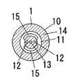
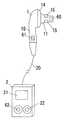
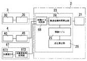
以下、本発明を添付図面に示す実施形態に基いて説明すると、この生体情報計測装置は人体の外耳道に挿入される外耳道挿入部11を備えたイヤーピース1と、このイヤーピース1にケーブル20で接続された本体2とからなるもので、上記イヤーピース1は図1及び図2に示すように、基部10とこの基部10から突出する外耳道挿入部11とからなるもので、シリコンゴムやウレタンゴム等の柔らかい材料で形成されて先端が根元よりも細くなっている外耳道挿入部11の先端部には2つの孔のあいたゴム片16が取り付けられて、該ゴム片16の各孔内に発光素子12と受光素子13とが配設されている。また、基部10における外耳道挿入部11の根元側部分には電極14を設けており、外耳道挿入部11の外周部にも電極15を設けてある。ただし、電極15は外耳道挿入部15の外周面から少し外方に突出するものとしているとともに、外耳道挿入部11の周方向において複数に分割したものとし、電極15,15間に隙間をあけている。そして基部10内には脈波検出部3と心電検出部4とを配置している。 Hereinafter, the present invention will be described based on an embodiment shown in the accompanying drawings. This biological information measuring apparatus is connected to an
上記イヤーピース1にケーブル20で接続された本体2は、液晶ディスプレー等からなる表示部21と電源スイッチ22とを外面に備えるともに、図3に示す演算部23や電源(図示せず)を備えたものである。 The
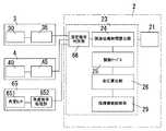
また、図3に示すように、上記脈波検出部3は脈波測定モジュール30と脈波信号処理部35とからなり、脈波測定モジュール30は上記発光素子12とこれを駆動する駆動回路31並びに上記受光素子14で構成され、脈波信号処理部35は増幅器36とノイズ除去フィルタ37とピーク検出器38で構成されており、前記心電検出部4は上記2つの電極14,15からなる心電測定モジュール40と、上記2つの電極14,15間の電位差を増幅する増幅器46とノイズ除去フィルター47とピーク検出器48とからなる心電波形信号処理部45とで構成されている。そして上記演算部23は、脈波伝搬時間算出部24と関数テーブル25と血圧算出部26で構成されている。 As shown in FIG. 3, the pulse
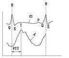
人体の外耳5は図4に示すように耳介50と外耳道51、その入り口側にある耳珠52、入り口下部にある耳甲介腔53で構成され、外耳道51はほぼ2.5cmの長さでS字状に湾曲するとともに外側1/3ほどの軟骨組織部54と残る2/3ほどの骨組織部55で形成されている。そして外耳道51の奥に位置する鼓膜56は図5に示すように直径約1cm、厚さ0.1mmの半透明膜で、細い動脈57が周囲から中心に向かって伸びている。 As shown in FIG. 4, the
上記の生体情報計測装置は、外耳道挿入部11を外耳道51に挿入した時、脈波と心電とを計測してこれらを基に血圧を算出するものである。すなわち、外耳道51に挿入された外耳道挿入部11の先端面に位置する発光素子12からの光で鼓膜56を照射するとともに鼓膜56からの反射光を受光素子13で受光する。この時、発光素子12としては、血液中のヘモグロビンに対する選択制の強い波長領域、たとえば940nmの波長の光を鼓膜56に照射するものを用いるものであり、鼓膜56の動脈にあたった光の一部はヘモグロビンで吸収されて残りが反射する。脈波の拍動に伴って上記反射光の強度が変化することから、上記反射光をフォトトランジスタ等の受光素子13で受光するとともに受光素子13の出力信号を処理することで、脈波波形(図7中のイ)を取り出すことができる。 When the external ear
また、外耳道挿入部11を外耳道51に挿入した時、電極14は耳甲介腔53に接触し、外耳道挿入部11に位置している電極15は軟骨組織部54と接触する。なお、電極15を複数に分割しているのは、外耳道51奥部への通気性の確保と、外耳道51の圧迫を抑えるためであり、この意味では電極15として外面に凹凸のあるものを用いるのも好ましい。 When the ear
そして上記両電極14,15で測定される電位差を処理することで心電波形(図7中のロ)を得るものであり、本体2の演算部23ではその脈波伝搬時間算出部24において、心電波形のピークRと脈波波形のピークTとの時間差から脈波伝搬時間PTTを算出する。この脈波伝搬時間PTTは図8に示すように血圧と相関関係があることが知られている。このために、予め上腕でカフなどを用いた血圧測定を併用することで最高血圧及び最低血圧と脈波伝播時間PTTとの間の関数テーブル25を作成しておけば、この関数テーブル25を参照することで脈波伝搬時間PTTから対応する血圧を算出することができるものであり、得られた血圧は表示部21に表示する。 Then, an electrocardiogram waveform (b in FIG. 7) is obtained by processing the potential difference measured at both
図9に示したものは、発光素子12として、中心波長が動脈中ヘモグロビンの赤色光の吸光度を測定するための630nmのものと、中心波長が動脈中ヘモグロビンの赤外光の吸光度を測定するための940nmのものの2つを用いたものを示している。波長の異なる光を用いることにより、酸素飽和度の算出も行うことができる。図10はこの場合のブロック図を示しており、脈波測定モジュール30では上記赤色光Rと赤外光IRとを交互に照射し、受光素子13にて検出された信号を脈波信号処理部35において脈動によるAC成分と非脈動によるDC成分(図11参照)に分け、夫々の波長のAC成分とDC成分の比から次式のrを算出する。
r=(ACR/DCR)/(ACIR/DCIR))
そして酸素飽和度算出部27において上記rの値から予め求めておいた関数により酸素飽和度を算出する。The
r = (ACR / DCR ) / (ACIR / DCIR ))
Then, the oxygen
図12に別の例を示す。これは血圧算出部26で求めた血圧値を時間情報とともにに蓄積する記憶装置28と、記憶装置28に蓄積した血圧値の変化を基に循環機能診断を行う循環機能新段部29を演算部23に設けて、たとえば夜間の睡眠中の一定時間毎の血圧変動と、予めデータベースとして蓄積されている心疾患と血圧変動の関係に基づいて循環機能診断を行うのである。 FIG. 12 shows another example. This includes a
上記記憶装置28に代えて、図13に示すようにネットワーク70を介して接続された管理サーバー71を用いて、該管理サーバー71に血圧値の変化を蓄積するようにしてもよく、この時、医療機関72も上記管理サーバー71にアクセスすることができるようにしておくことで、担当医師が適切な診断を行うこともできるものとなる。また、ここでは血圧変動から循環機能を診断するようにしているが、心拍変動や酸素飽和度の変動を用いて自律神経機能や睡眠時無呼吸症候群を診断することも可能である。 Instead of the
図14及び図15に示したものは、算出した血圧値を音声に変換する変換部601とスピーカ602とからなる音声出力部60を設けるとともに、少なくともスピーカ602をイヤーピース1側に配したものを示している。測定した血圧値を音声で知らせることができるものであり、表示部21を見なくても使用者は血圧値を知ることができる。この時、切換釦61の操作で表示部21側への表示を止めることができるようにして、音声のみで知らせることができるようにしておくと、血圧測定結果や血圧測定中であることを他人に知られることがないものとなる。 14 and 15 show a configuration in which an
また図16に示すように、イヤーピース1にマイクロフォン63を内蔵させてこのマイクロフォン63で拾った音声を増幅してスピーカ602に出力する補聴器機能を付加することも好ましい。なお、図14及び図16における図中の62はボリュームである。 Further, as shown in FIG. 16, it is also preferable to add a hearing aid function in which a
図17に別の例を示す。これは角度センサ651と角度信号処理部652とからなる角度検出部65を設けるとともに、少なくとも角度センサ651をイヤーピース1に内蔵させ、更に本体2側には角度検出部65の出力信号から測定姿勢を判別する測定姿勢判別部66を設けたものである。使用者が寝ているか起きているかを角度検出部65の出力信号を基に判別することで、たとえば起立性低血圧であるかどうかを診断することができるものとなる。すなわち、使用者が仰臥位にある時(角度ゼロ)の血圧値と、上半身を起こした状態(角度90°)での血圧値との差が所定値以上であれば、起立性低血圧であると診断することができる。 FIG. 17 shows another example. This is provided with an
図18は加速度センサ671と加速度信号処理部672とからなる体動検出部67を設けるとともに、少なくとも加速度センサ671をイヤーピース1側に配し、本体2側には体動レベル判別部68を設けたものを示している。加速度センサ67の出力は加速度信号処理部672において増幅・フィルタリングされた後、体動レベル判別部68において所定の閾値を越えたかどうかの判定がなされ、上記閾値を超える場合には脈波検出部3及び心電検出部4からの信号を除去し、上記閾値以下であれば前述の血圧値算出を行う。体動による影響を受けることなく血圧測定を行うことができる。 In FIG. 18, a body
体動検出部67と脈波検出部3と心電検出部4の各出力信号をフーリエ変換により周波数成分別に分け、脈波信号及び心電信号の周波数成分から体動検出信号の周波数成分を除去した後、フーリエ変換により周波数成分に分け、脈波信号と心電信号の周波数成分から体動信号の周波数成分を除去した後、該フーリエ変換で体動成分のない脈波信号及び心電信号に戻して、ここから血圧値を算出することもでき、この場合、歩行時や食事中などの体動がある状態においても血圧を測定することができる。 The output signals of the body
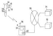
上記の各例ではイヤーピース1と本体2とをケーブル20で接続したものを示したが、図19に示すように、上記両者1,2間を無線通信機能で接続するようにしてもよく、この場合、近距離無線通信方式の1つであるBluetoothを好適に用いることができる。図中75は無線送信部、76は無線受信部である。ケーブル20が無いために、イヤーピース1の装着感を向上させることができるとともにイヤーピース1の位置ずれが起こりにくくなる。なお、本体2はネットワーク70を介して管理サーバー71に接続される携帯電話のような移動通信端末であってもよく、在宅で使用している患者の緊急時において医療機関72による迅速な対応が可能となる。 In each of the above examples, the
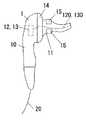
図20はイヤーピース1における外耳道挿入部11をシリコン樹脂などの柔らかく且つ弾性変形可能な材料でS字状に形成したものを示している。この場合、発光素子12及び受光素子13は基部10側に配置し、これらに一端を対向させた光ファイバー120,130の各他端を外耳道挿入部11の先端面に位置させることが好ましい。外耳道挿入部11を外耳道51にフィットした形状とすることができるために、イヤーピース1の位置ずれが起こりにくくなり、高い信号レベルでの測定を行うことができる。 FIG. 20 shows the ear
図21に示すように、外耳道挿入部11の外周面に圧迫体77を配置するとともに、基部10側にマイクロポンプ78及びマイクロ圧力計79を配したもので、たとえば厚さ0.1mm程度のウレタンやシリコンなどで形成された圧迫体77は、マイクロポンプ78から供給される空気圧で膨らんで外耳道51内面に密着することで、測定中のイヤーピース1の位置ずれを防いで、より正確な脈波情報や心電情報の取得を補助する。なお、圧迫体77の膨張は血圧測定時のみとし、非測定時には収縮するようにしておくことで、外耳道51の側部にある動脈がうっ血してしまったり、長時間の過剰な圧迫で炎症が生じてしまったりすることを防ぐことができる。 As shown in FIG. 21, a
また、圧迫体77を所定値まで加圧し、その後、一定速度で減圧させることにより、外耳道51の側部にある動脈の振動を検出し、得られた振動成分からオシロメトリック法により血圧を測定することもできる。この場合、血圧値と脈波伝搬時間との間で校正を行う際に上腕血圧計が不要となるために、操作が一層簡単なものとなる。 Further, the pressure of the
図22に示すものは、イヤーピース1における基部10に対して外耳道挿入部11を着脱自在としたものであり、図中81,82は着脱自在な係合連結部を示している。なお、この着脱に際しては、電極15や発光素子12や受光素子などへの配線の途中に設けたコネクタ(図示せず)も着脱されるものとしている。外耳道挿入部11が汚れた場合など、基部10から取り外して洗浄したり他の新品の外耳道挿入部11への交換などに応ずることができる。 In FIG. 22, the ear
1 イヤーピース
10 基部
11 外耳道挿入部
12 発光素子
13 受光素子
14 電極
15 電極DESCRIPTION OF
Claims (12)
Translated fromJapanesePriority Applications (1)
| Application Number | Priority Date | Filing Date | Title |
|---|---|---|---|
| JP2005211768AJP2007021106A (en) | 2005-07-21 | 2005-07-21 | Biological information-measuring device |
Applications Claiming Priority (1)
| Application Number | Priority Date | Filing Date | Title |
|---|---|---|---|
| JP2005211768AJP2007021106A (en) | 2005-07-21 | 2005-07-21 | Biological information-measuring device |
Publications (1)
| Publication Number | Publication Date |
|---|---|
| JP2007021106Atrue JP2007021106A (en) | 2007-02-01 |
Family
ID=37782617
Family Applications (1)
| Application Number | Title | Priority Date | Filing Date |
|---|---|---|---|
| JP2005211768AWithdrawnJP2007021106A (en) | 2005-07-21 | 2005-07-21 | Biological information-measuring device |
Country Status (1)
| Country | Link |
|---|---|
| JP (1) | JP2007021106A (en) |
Cited By (17)
| Publication number | Priority date | Publication date | Assignee | Title |
|---|---|---|---|---|
| JP2009247513A (en)* | 2008-04-04 | 2009-10-29 | Hitachi Ltd | Biological light measurement apparatus |
| JP2010125147A (en)* | 2008-11-28 | 2010-06-10 | Hamamatsu Photonics Kk | Biometric instrument |
| JP2012530563A (en)* | 2009-07-02 | 2012-12-06 | ヴェーデクス・アクティーセルスカプ | Ear plug with surface electrode |
| JP2013039160A (en)* | 2011-08-11 | 2013-02-28 | Advance Co Ltd | Beautification and health monitoring system |
| JP2013510678A (en)* | 2009-11-12 | 2013-03-28 | ネルコー ピューリタン ベネット エルエルシー | Hybrid physiological sensor system and method |
| JP2014215963A (en)* | 2013-04-30 | 2014-11-17 | 株式会社Nttドコモ | Earphone and eyeball movement estimation device |
| JP2017500076A (en)* | 2013-11-01 | 2017-01-05 | メドトロニック モニタリング インコーポレイテッド | Congestive heart failure risk state determination method and related apparatus |
| JP2018504157A (en)* | 2014-11-25 | 2018-02-15 | イノヴァ デザイン ソリューション エルティーディーInova Design Solutions Ltd | Portable physiological monitor |
| JP2018108467A (en)* | 2009-02-25 | 2018-07-12 | ヴァレンセル,インコーポレイテッド | Monitor device |
| CN111466907A (en)* | 2019-01-24 | 2020-07-31 | 富士施乐株式会社 | Biological information measurement device and biological information measurement system |
| JP2021048957A (en)* | 2019-09-24 | 2021-04-01 | カシオ計算機株式会社 | Biological information detection device |
| JP2021150949A (en)* | 2020-03-18 | 2021-09-27 | 日月光半導体製造股▲ふん▼有限公司 | Ear chip and wearable device including the same |
| WO2021246264A1 (en)* | 2020-06-01 | 2021-12-09 | 株式会社Arblet | Server, adjustment information provision method, and program |
| JP2022509133A (en)* | 2018-11-26 | 2022-01-20 | オソン メディカル イノベーション ファウンデーション | Deep body temperature measuring instrument with battery charging structure |
| US11426125B2 (en) | 2009-02-16 | 2022-08-30 | Masimo Corporation | Physiological measurement device |
| US11471103B2 (en) | 2009-02-25 | 2022-10-18 | Valencell, Inc. | Ear-worn devices for physiological monitoring |
| WO2022265381A1 (en)* | 2021-06-17 | 2022-12-22 | 주식회사 바이오넷 | Ear-wearable sensor probe for measuring oxygen saturation |
- 2005
- 2005-07-21JPJP2005211768Apatent/JP2007021106A/ennot_activeWithdrawn
Cited By (38)
| Publication number | Priority date | Publication date | Assignee | Title |
|---|---|---|---|---|
| JP2009247513A (en)* | 2008-04-04 | 2009-10-29 | Hitachi Ltd | Biological light measurement apparatus |
| JP2010125147A (en)* | 2008-11-28 | 2010-06-10 | Hamamatsu Photonics Kk | Biometric instrument |
| US11426125B2 (en) | 2009-02-16 | 2022-08-30 | Masimo Corporation | Physiological measurement device |
| US11877867B2 (en) | 2009-02-16 | 2024-01-23 | Masimo Corporation | Physiological measurement device |
| US11432771B2 (en) | 2009-02-16 | 2022-09-06 | Masimo Corporation | Physiological measurement device |
| US11471103B2 (en) | 2009-02-25 | 2022-10-18 | Valencell, Inc. | Ear-worn devices for physiological monitoring |
| US11660006B2 (en) | 2009-02-25 | 2023-05-30 | Valencell, Inc. | Wearable monitoring devices with passive and active filtering |
| US10898083B2 (en) | 2009-02-25 | 2021-01-26 | Valencell, Inc. | Wearable monitoring devices with passive and active filtering |
| US10842389B2 (en) | 2009-02-25 | 2020-11-24 | Valencell, Inc. | Wearable audio devices |
| JP2018108467A (en)* | 2009-02-25 | 2018-07-12 | ヴァレンセル,インコーポレイテッド | Monitor device |
| US10448840B2 (en) | 2009-02-25 | 2019-10-22 | Valencell, Inc. | Apparatus for generating data output containing physiological and motion-related information |
| US10716480B2 (en) | 2009-02-25 | 2020-07-21 | Valencell, Inc. | Hearing aid earpiece covers |
| US10750954B2 (en) | 2009-02-25 | 2020-08-25 | Valencell, Inc. | Wearable devices with flexible optical emitters and/or optical detectors |
| US11589812B2 (en) | 2009-02-25 | 2023-02-28 | Valencell, Inc. | Wearable devices for physiological monitoring |
| US9408552B2 (en) | 2009-07-02 | 2016-08-09 | Widex A/S | Ear plug with surface electrodes |
| JP2012530563A (en)* | 2009-07-02 | 2012-12-06 | ヴェーデクス・アクティーセルスカプ | Ear plug with surface electrode |
| US11161306B2 (en) | 2009-07-02 | 2021-11-02 | T&W Engineering A/S | Ear plug with surface electrodes |
| JP2013510678A (en)* | 2009-11-12 | 2013-03-28 | ネルコー ピューリタン ベネット エルエルシー | Hybrid physiological sensor system and method |
| JP2013039160A (en)* | 2011-08-11 | 2013-02-28 | Advance Co Ltd | Beautification and health monitoring system |
| JP2014215963A (en)* | 2013-04-30 | 2014-11-17 | 株式会社Nttドコモ | Earphone and eyeball movement estimation device |
| JP2017500076A (en)* | 2013-11-01 | 2017-01-05 | メドトロニック モニタリング インコーポレイテッド | Congestive heart failure risk state determination method and related apparatus |
| JP2022008652A (en)* | 2014-11-25 | 2022-01-13 | イノヴァ デザイン ソリューション エルティーディー | Portable physiology monitor |
| JP7255906B2 (en) | 2014-11-25 | 2023-04-11 | イノヴァ デザイン ソリューション エルティーディー | portable physiological monitor |
| JP2018504157A (en)* | 2014-11-25 | 2018-02-15 | イノヴァ デザイン ソリューション エルティーディーInova Design Solutions Ltd | Portable physiological monitor |
| JP7152607B2 (en) | 2018-11-26 | 2022-10-12 | オソン メディカル イノベーション ファウンデーション | Core body temperature measuring device with battery charging structure |
| JP2022509133A (en)* | 2018-11-26 | 2022-01-20 | オソン メディカル イノベーション ファウンデーション | Deep body temperature measuring instrument with battery charging structure |
| JP2023156517A (en)* | 2019-01-24 | 2023-10-24 | 株式会社Agama-X | Biological information measuring device |
| JP2020116369A (en)* | 2019-01-24 | 2020-08-06 | 富士ゼロックス株式会社 | Biological information measuring apparatus and biological information measuring system |
| CN111466907A (en)* | 2019-01-24 | 2020-07-31 | 富士施乐株式会社 | Biological information measurement device and biological information measurement system |
| US11717219B2 (en) | 2019-01-24 | 2023-08-08 | Agama-X Co., Ltd. | Biological information measuring apparatus and biological information measuring system |
| JP7343160B2 (en) | 2019-01-24 | 2023-09-12 | 株式会社Agama-X | Biological information measuring device and biological information measuring system |
| JP7607361B2 (en) | 2019-01-24 | 2024-12-27 | 株式会社Agama-X | Biological information measuring device |
| JP2021048957A (en)* | 2019-09-24 | 2021-04-01 | カシオ計算機株式会社 | Biological information detection device |
| JP7379995B2 (en) | 2019-09-24 | 2023-11-15 | カシオ計算機株式会社 | Biological information detection device |
| JP2021150949A (en)* | 2020-03-18 | 2021-09-27 | 日月光半導体製造股▲ふん▼有限公司 | Ear chip and wearable device including the same |
| WO2021246264A1 (en)* | 2020-06-01 | 2021-12-09 | 株式会社Arblet | Server, adjustment information provision method, and program |
| JP2021186639A (en)* | 2020-06-01 | 2021-12-13 | 株式会社Arblet | Server, adjustment information provision method and program |
| WO2022265381A1 (en)* | 2021-06-17 | 2022-12-22 | 주식회사 바이오넷 | Ear-wearable sensor probe for measuring oxygen saturation |
Similar Documents
| Publication | Publication Date | Title |
|---|---|---|
| JP6672489B2 (en) | Personal health data collection | |
| KR101951815B1 (en) | Ear wearing type health care monitoring system | |
| US20150182132A1 (en) | Mobile device system for measurement of cardiovascular health | |
| JP2007021106A (en) | Biological information-measuring device | |
| JP6210154B2 (en) | Biological signal detection device | |
| EP3295867B1 (en) | A phone for use in health monitoring | |
| JP6006254B2 (en) | System for measuring and recording user vital signs | |
| JP6692420B2 (en) | Auxiliary device for blood pressure measurement and blood pressure measurement device | |
| WO2014165312A2 (en) | Ear-related devices implementing sensors to acquire physiological characteristics | |
| EP3840410B1 (en) | Heart rate measurements with hearing device using in/at/on-ear sensor, second body sensor and app | |
| KR20190081527A (en) | Earphone for monitoring blood pressure and method for monitoring blood pressure using the same | |
| JP2006102190A (en) | Blood pressure monitor, blood pressure correction method, and measurement start pressure correction method | |
| JP6379297B2 (en) | Biological signal detection device | |
| JP2004081285A (en) | Portable type blood pressure measuring instrument | |
| CN112515627A (en) | Combined type physiological detection device | |
| US20250049322A1 (en) | An apparatus and method for capturing biometric data from a human or other animal | |
| KR102734578B1 (en) | Smart healthcare device | |
| CN118574563A (en) | Apparatus and method for capturing biometric data from a person or other animal | |
| US20230363653A1 (en) | Wearable vital signs monitoring device and method | |
| GB2613671A (en) | An apparatus and method for capturing biometric data from a human or other animal | |
| KR20220106606A (en) | Wearable device capable of continuously measuring blood pressure | |
| CN117479882A (en) | Biological information measuring device and biological information processing system | |
| JP2006102249A (en) | Blood pressure index measuring device, blood pressure index measuring method, control program, and computer-readable storage medium |
Legal Events
| Date | Code | Title | Description |
|---|---|---|---|
| A300 | Withdrawal of application because of no request for examination | Free format text:JAPANESE INTERMEDIATE CODE: A300 Effective date:20081007 |