JP2007021084A - Endoscope - Google Patents
EndoscopeDownload PDFInfo
- Publication number
- JP2007021084A JP2007021084AJP2005211430AJP2005211430AJP2007021084AJP 2007021084 AJP2007021084 AJP 2007021084AJP 2005211430 AJP2005211430 AJP 2005211430AJP 2005211430 AJP2005211430 AJP 2005211430AJP 2007021084 AJP2007021084 AJP 2007021084A
- Authority
- JP
- Japan
- Prior art keywords
- light
- optical system
- observation
- light emitting
- endoscope
- Prior art date
- Legal status (The legal status is an assumption and is not a legal conclusion. Google has not performed a legal analysis and makes no representation as to the accuracy of the status listed.)
- Pending
Links
Images


Landscapes
- Instruments For Viewing The Inside Of Hollow Bodies (AREA)
- Endoscopes (AREA)
Abstract
Translated fromJapaneseDescription
Translated fromJapaneseこの発明は、例えば医療用や工業用など、種々の用途に使用される内視鏡に関する。 The present invention relates to an endoscope used for various applications such as medical use and industrial use.
内視鏡システムにおいて、例えば体腔内を照明する手段として筐体装置内で点灯するランプの光をライトガイドを通して内視鏡の挿入部の先端まで導光している。近年は発光素子の小型化、大光量化が進み、これらを内視鏡の挿入部の先端に配置する内視鏡システムが提案されている。 In an endoscope system, for example, as a means for illuminating the inside of a body cavity, light from a lamp that is lit in a housing device is guided to the distal end of an insertion portion of the endoscope through a light guide. In recent years, light-emitting elements have been reduced in size and light intensity, and an endoscope system has been proposed in which these are arranged at the distal end of an insertion portion of the endoscope.
例えば特許文献1には、先端に赤(R)、緑(G)および青(B)の各色の発光素子を有する内視鏡が開示されている。 For example, Patent Literature 1 discloses an endoscope having light emitting elements of red (R), green (G), and blue (B) at the tip.
また、特許文献2および特許文献3には、多数の発光素子を内視鏡の挿入部の先端部に配設する内視鏡が開示されている。この内視鏡の挿入部の先端部の発光素子は、白色のものが使用されている。
図9(A)および図9(B)に示すように、挿入部の先端部本体222には、観察光学系242と、照明光学系244と、処置具挿通チャンネル246と、送気送水ノズル256とが配設されている。このうち、照明光学系244は、例えば赤色、緑色および青色の3色のLED264R,264G,264Bが配置されている。
特許文献1に開示された内視鏡のようにRGBの各色の発光素子を、特許文献2および特許文献3に開示された、白色の発光素子を用いた内視鏡に適用することができる。しかし、発光素子(ここでいうLED)は、図9(A)および図9(B)に示すように、観察光学系242の中心軸(光軸)に対して非対称に配置されている。このため、観察光学系242の中心軸に直交する面状であると仮定する観察対象物に光が照射されると、観察像の部位α,βによっては光の強度に偏りを生じる。すなわち、図9(A)に示すように、観察像には一定方向に明るさの強弱が生じている。さらに、その強弱の方向がR光、G光およびB光で異なっている。このため、画像処理によって観察対象物の像を合成したときに、色同士が分離した状態でモニタに表示されて観察される。 As in the endoscope disclosed in Patent Document 1, light emitting elements of each color of RGB can be applied to endoscopes using white light emitting elements disclosed in
この発明は、このような課題を解決するためになされたものであり、その目的とするところは、観察時の色分離を軽減させることが可能な内視鏡を提供することにある。 The present invention has been made to solve such a problem, and an object thereof is to provide an endoscope capable of reducing color separation during observation.
上記課題を解決するために、この発明に係る内視鏡は、細長い挿入部と、この挿入部の基端部に設けられた操作部とを備えている。前記挿入部の先端部には、観察対象物を照明する発光素子を有する照明光学系と、前記観察対象物を観察する観察光学系とが配設されている。そして、前記発光素子は、前記観察光学系の中心軸を中心として略対称の位置に対に配置されていることを特徴とする。 In order to solve the above problems, an endoscope according to the present invention includes an elongated insertion portion and an operation portion provided at a proximal end portion of the insertion portion. An illumination optical system having a light emitting element for illuminating the observation object and an observation optical system for observing the observation object are disposed at the distal end of the insertion part. The light emitting elements are arranged in pairs at substantially symmetrical positions around the central axis of the observation optical system.
このため、観察光学系に対して対称の位置に配置された発光素子が発光することによって、観察光学系の中心軸(光軸)の位置の光の強さを両方向に対して一致させることができる。したがって、異なる色の発光素子であっても、観察光学系の中心軸上で、それぞれの色の光の強さをそれぞれ調整することができるので、画像処理によって重ね合わせたときの色分離状態が軽減される。 For this reason, when the light emitting element arranged at a position symmetrical to the observation optical system emits light, the intensity of light at the position of the central axis (optical axis) of the observation optical system can be made to coincide with both directions. it can. Therefore, even with light emitting elements of different colors, the intensity of light of each color can be adjusted on the central axis of the observation optical system, so that the color separation state when superimposed by image processing is It is reduced.
また、上記課題を解決するために、この発明に係る内視鏡は、この発明に係る内視鏡は、細長い挿入部と、この挿入部の基端部に設けられた操作部とを備えている。前記挿入部の先端部には、観察対象物を照明する発光素子を有する照明光学系と、前記観察対象物を観察する観察光学系とが配設されている。そして、前記発光素子は、前記観察光学系の中心軸を重心とする略正多角形の頂点の位置に配置されていることを特徴とする。 In order to solve the above problems, an endoscope according to the present invention includes an elongated insertion portion and an operation portion provided at a proximal end portion of the insertion portion. Yes. An illumination optical system having a light emitting element for illuminating the observation object and an observation optical system for observing the observation object are disposed at the distal end of the insertion part. The light emitting element is arranged at the position of the apex of a substantially regular polygon having the center axis of the observation optical system as the center of gravity.
このため、観察光学系を重心の位置として略正多角形の頂点の位置に配置された発光素子が発光することによって、観察光学系の中心軸(光軸)の位置の光の強さを一致させることができる。したがって、異なる色の発光素子であっても、観察光学系の中心軸上で、それぞれの色の光の強さをそれぞれ調整することができるので、画像処理によって重ね合わせたときの色分離状態が軽減される。 For this reason, the intensity of light at the central axis (optical axis) of the observation optical system is matched by the light emitting element arranged at the position of the apex of the substantially regular polygon with the observation optical system as the center of gravity. Can be made. Therefore, even with light emitting elements of different colors, the intensity of light of each color can be adjusted on the central axis of the observation optical system, so that the color separation state when superimposed by image processing is It is reduced.
また、前記発光素子は、前記観察光学系の中心軸を中心とする同心円上に配置されていることが好適である。 Moreover, it is preferable that the light emitting elements are arranged on concentric circles centering on the central axis of the observation optical system.
このため、異なる色の発光素子に対する観察光学系の中心軸までの距離を、他の異なる色の発光素子に対する観察光学系の中心軸までの距離に対して等距離もしくは異なる距離に配置した場合であっても、異なる色同士で光の強弱を調整することによって、画像処理によって重ね合わせたときの色分離状態が軽減される。 Therefore, when the distance to the central axis of the observation optical system with respect to the light emitting elements of different colors is arranged at the same distance or different distance from the distance to the central axis of the observation optical system with respect to the light emitting elements of different colors. Even in such a case, by adjusting the intensity of light between different colors, the color separation state when superimposed by image processing is reduced.
また、前記発光素子は、赤色、緑色および青色のものをそれぞれ対に備えていることが好適である。 In addition, it is preferable that the light-emitting elements include red, green, and blue elements in pairs.
このため、ホワイトバランスを調整しつつ、通常観察や蛍光観察等を行なうことができる。 For this reason, normal observation, fluorescence observation, etc. can be performed while adjusting the white balance.
また、前記発光素子は、前記赤色、緑色および青色の補色のものであることが好適である。 Moreover, it is preferable that the light emitting element is a complementary color of the red, green, and blue.
このため、上記赤色、緑色および青色と同様に作用させることができるので、ホワイトバランスを調整しつつ、通常観察や蛍光観察等を行なうことができる。 For this reason, since it can be made to act similarly to said red, green, and blue, normal observation, fluorescence observation, etc. can be performed, adjusting white balance.
この発明によれば、観察時の色分離を軽減させることが可能な内視鏡を提供することができる。 According to the present invention, an endoscope capable of reducing color separation during observation can be provided.
以下、図面を参照しながらこの発明を実施するための最良の形態(以下、実施の形態という)について説明する。
第1の実施の形態について図1ないし図7を用いて説明する。The best mode for carrying out the present invention (hereinafter referred to as an embodiment) will be described below with reference to the drawings.
A first embodiment will be described with reference to FIGS.
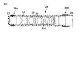
図1に示すように、内視鏡10は、例えば体腔内等の観察部位に挿入される細長い挿入部12と、この挿入部12の基端側に配設された把持部を兼ねる操作部14と、この操作部14の側部から延出されたユニバーサルコード16とを備えている。 As shown in FIG. 1, an
挿入部12は、硬質の先端部本体22と、例えば上下方向や左右方向に湾曲自在に連接させた複数の湾曲駒32(図2参照)を有する湾曲部24と、柔軟で可撓性を有する軟性管26とを先端側から基端側に向かって備えている。すなわち、軟性管26の基端部は操作部14に接続されている。 The
図2に示すように、湾曲部24は、枢軸32aによって互いに対して回動可能な複数の湾曲駒32と、これら湾曲駒32を覆う網状管34と、この網状管34の外周を覆う湾曲部用被覆チューブ(外皮)36とを備えている。被覆チューブ36は、弾力性を有する例えばゴム材により形成されている。 As shown in FIG. 2, the
先端部本体22と湾曲部24の被覆チューブ36との連結部は、糸が巻回された上に接着剤が塗布されて形成された第1の糸巻部38aによって固定されている。一方、湾曲部24の被覆チューブ36の外周面と軟性管26との連結部は、糸が巻回された上に接着剤が塗布されて形成された第2の糸巻部38bによって固定されている。 The connecting portion between the distal end portion
図3および図4に示すように、先端部本体22には、観察光学系42と、照明光学系44と、処置具挿通チャンネル46とが配設されている。このうち、観察光学系42および処置具挿通チャンネル46は、挿入部12の湾曲部24および軟性管26を通して操作部14に配設されている。観察光学系42は、挿入部12の先端部から、操作部14を通してユニバーサルコード16の端部の電気コネクタ(図示せず)に挿通されている。図1に示すように、処置具挿通チャンネル46の基端部、すなわち、鉗子などの挿入位置には、鉗子栓46aが配設されている。 As shown in FIGS. 3 and 4, the distal end
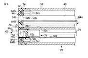
図3に示すように、挿入部12の先端部本体22は、例えばステンレス鋼材製の先端枠部材52と、この先端枠部材52の先端に配設された樹脂材製の先端カバー54とを備えている。先端枠部材52の先端には先端カバー54が固定されている。先端カバー54には、照明光学系44の後述する基板62およびLED(半導体発光素子)64R,64G,64Bが埋設されている。先端カバー54は、例えば透明なエポキシ樹脂により形成されている。 As shown in FIG. 3, the distal end portion
先端枠部材52および先端カバー54には、観察光学系42が配設される撮像用ホール52a,54aと、処置具挿通チャンネル46を形成し、鉗子(図示せず)を挿入するための鉗子用ホール52b,54bと、送気送水用ホール52c,54cとがそれぞれ形成されている。基板62にも同様に撮像用ホール62a、鉗子用ホール62bおよび送気送水用ホール62cが形成されている。これら撮像用ホール52a,54a,62a、鉗子用ホール52b,54b,62b、および送気送水用ホール52c,54c,62cはそれぞれ連通された状態にある。なお、先端カバー54の先端面には、送気送水用ホール62cを通した気体または液体を観察光学系42に偏向させる送気送水ノズル56が固定されている。 The distal
観察光学系42は、対物レンズユニット72と、この対物レンズユニット72の基端部に配設された撮像ユニット74と、この撮像ユニット74の基端部から延出された信号ケーブル76とを備えている。
撮像ユニット74は、CCD(撮像素子)74aを備えている。このCCD74aは、後述する第2の実施の形態で説明するが、通常光による観察だけでなく、特殊光を観察対象物に照明したときにその特殊光による観察像を撮像可能な特性を備えている。すなわち、CCD74aは、通常光による波長を取り込むだけでなく、特殊光による波長を取り込むように、適宜に感度が設定されたものが使用されている。したがって、このCCD74aは、広帯域のものが使用されている。また、CCD74aは、適宜の波長を強調して撮像可能であり、すなわち、適宜の波長の光をカットする例えば電子フィルタを有することが好ましい。The observation
The
このような制御を行なうため、このCCD74aは、後述するビデオプロセッサ80に電気的に接続された状態で使用される。このCCD74aからは複数の信号線が延出されている。これら信号線は、信号ケーブル76の内部にまとめられている。信号ケーブル76は、電気コネクタ(図示せず)に電気的に接続されている。 In order to perform such control, the
対物レンズユニット72は、レンズ枠(遮光部材)72aと、このレンズ枠72a内に配設されたレンズ系72bとを備えている。このレンズ枠72aの基端部には、CCD74aが固定されている。レンズ系72bのレンズ群は、少なくとも一部がレンズ枠72aの軸方向に沿って移動可能である。このため、CCD74aは、観察対象物の像の焦点をCCD74a上で結んだ状態で観察対象物の像を撮像可能である。レンズ枠72aは、外側からの光の入射を遮断するため、例えば黒色であることが好適である。
レンズ系72bは、励起光カットフィルタ(図示せず)を備えている。この励起光カットフィルタは、例えば後述するB光用LED64Bを発光させて自家蛍光を発生させて蛍光観察を行なうときに、その出射光(蛍光励起光)の反射光(蛍光励起光)を遮光するものである。この励起光カットフィルタはレンズ系72bに対して挿脱可能である。The
The
なお、撮像用ホール52a,54a,62aのうち、特に、符号54aで示す撮像用ホールの内周面は、遮光のために黒色にコーティングされていることも好適である。この場合、レンズ枠72aは必ずしも必要でない。 Of the
一方、照明光学系44は、上述したように、基板62と、赤色発光用(R光用)、緑色発光用(G光用)および青色発光用(B光用)のLED64R,64G,64Bとを備えている。図4に示すように、基板62上には、LED64R,64G,64Bが配設されている。このため、複数のLED64R,64G,64Bは、各色同士で電気的に接続されている。すなわち、基板から例えば3つの系統(3対)のケーブルが延出されて上述した電気コネクタに電気的に接続されている。 On the other hand, as described above, the illumination
ここでは、これらLED64R,64G,64Bは、観察光学系42の中心軸を同一の中心として同一円周上に配設されている。すなわち、R光用、G光用およびB光用のLED64R,64G,64Bは、観察光学系42の中心軸に対してそれぞれ略対称となる位置に配置されている。このため、観察光学系42および1対のR光用LED64Rの各中心軸は、略一直線上に配置されている。同様に、観察光学系42および1対のG光用LED64Gの各中心軸は、略一直線上に配置されている。さらに、観察光学系42および1対のB光用LED64Bの各中心軸は、略一直線上に配置されている。このため、LED64R,64G,64Bと観察光学系42上における光の強弱の差が軽減される。 Here, these
ここで、LED64R,64G,64Bは、基板62の一側面に配設されている。これらLED64R,64G,64Bのケーブル64a,64b,64cは基板62の他側面から延出され、湾曲部24、軟性管26、および操作部14を通してユニバーサルコード16の電気コネクタに電気的に接続されている。このため、LED64R,64G,64Bは、ビデオプロセッサ80に電気的に接続された状態で使用される。 Here, the
なお、基板62の一側面(表面)は、例えば白色にシルク印刷されていることが好適である。そうすると、LED64R,64G,64Bの発光による反射光がこの基板62に反射して前方、すなわち、先端カバー54から出射される光量が増す。
また、先端カバー54には、蛍光材が含有されていることが好適である。そうすると、LED64R,64G,64Bによる光が蛍光材によってより輝度を高くして先端カバー54から発光させることができる。Note that one side surface (surface) of the
The tip cover 54 preferably contains a fluorescent material. If it does so, the light by LED64R, 64G, 64B can make it light-emit from the front-end | tip cover 54 by making a brightness | luminance higher by a fluorescent material.
プロセッサ80は、以下に説明する構成を備えている。
図5に示すように、LED64R,64G,64Bには、LEDドライバ112と、D/Aコンバータ114と、調光回路116とが順に接続されている。図6に示すように、調光回路116は、輝度レベル検波回路122と、コンパレータ124と、ループフィルタ126とを備えている。The
As shown in FIG. 5, an
また、図5に示すように、CCD74aには、CCDドライバ132と、タイミングジェネレータ134と、SSG(Standard Signal Generator)136と、タイミングコントローラ138とが順に接続されている。さらに、CCD74aには、プリアンプ142と、CDS(Correlated Double Sampling)回路144と、A/Dコンバータ146と、映像信号処理回路148と、D/Aコンバータ150と、プリアンプ152とが順に接続されている。このプリアンプ152には、モニタ(図示せず)が接続されている。 As shown in FIG. 5, a
さらに、調光回路116には、CPU162と、タイミングコントローラ138と、上述した映像信号処理回路148とがそれぞれ接続されている。映像信号処理回路148には、タイミングコントローラ138と、CPU162とがそれぞれ接続されている。 Further, the
さらに、図示しないが、映像信号処理回路148は、Rフレームメモリ、GフレームメモリおよびBフレームメモリを備えている。Rフレームメモリは、R光が先端カバー54から出射されたときに駆動されて、対物レンズユニット72の対物レンズ系72bに入射されてCCD74aにより撮像されたデータを格納する。Gフレームメモリは、G光が先端カバー54から出射されたときに駆動されてCCD74aにより撮像されたデータを格納する。さらに、Bフレームメモリは、B光が先端カバー54から出射されたときに駆動されてCCD74aにより撮像されたデータを格納する。 Further, although not shown, the video
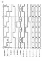
CCD74aは、電子シャッタ機能を備えている。CCD74aは、電子シャッタ機能によって所定時間ごとに露光状態/遮光状態が変化する。ここでは、例えば、LED64R,64G,64Bのいずれかの発光とともに露光状態となり、全てのLED64R,64G,64Bの消灯とともに遮光状態となるように設定されていることが好ましい。 The
なお、図7に示す垂直同期信号は、CCD74aをフィールドごとに映像信号処理回路148と同期させるためにタイミングジェネレータ134、SSG136、タイミングコントローラ138などに使用される。 7 is used by the
次に、この実施の形態に係る内視鏡10の作用について説明する。ここでは、まず、通常観察を行なう場合について説明する。
内視鏡10のプロセッサ80のスイッチ(図示せず)をONに切り替えると、SSG136から信号を出力する。このSSG136からの信号が入力されたタイミングコントローラ138は、調光回路116に信号を出力する。すると、D/Aコンバータ114は、その信号をD/A変換する。変換された信号はLEDドライバ112に入力される。このLEDドライバ112は、R光用LED64Rを駆動させる。Next, the operation of the
When a switch (not shown) of the
すなわち、LED64Rのケーブル64aに対して制御された時間だけ点灯電圧を印加する。すると、基板62上のLED64Rが発光する。ここで、LED64Rは基板62上に配設されているので、基板62の一側面から発光する。そうすると、透明な先端カバー54の略全体からLED64Rの発光による光が出射される。このとき、1対のLED64Rの略中央に観察光学系42が配設されているので、1対のLED64Rを同じ光量で発光させれば、通常は、観察光学系42の中心軸付近が明るくなる。また、観察光学系42の中心軸に沿ったLED64Rの垂直前方も明るくなるので、これら観察光学系42およびLED64Rの間の明るさの強弱の差が軽減される。 That is, the lighting voltage is applied to the
一方、SSG136は、タイミングジェネレータ134に信号を出力する。このタイミングジェネレータ134はCCDドライバ132を駆動させる。そして、CCDドライバ132はCCD74aを駆動させる。すなわち、LED64Rの発光により照明した観察対象物の像を対物レンズユニット72を通してCCD74aで撮像する。撮像した像のデータ信号はプリアンプ142によって増幅されてCDS回路144に入力される。CDS回路144を通したデータ信号はA/Dコンバータ146によってA/D変換される。そして、この信号が映像信号処理回路148に入力される。このため、CCD74aで撮像された像のデータは、R光を発光させた直後にRフレームメモリに書き込まれる。 On the other hand, the
R光用LED64Rに対する電力の供給を止めた後、G光用LED64Gに電力を供給して発光させる。このとき、1対のLED64Gの略中央に観察光学系42が配設されているので、1対のLED64Gを同じ光量で発光させれば、通常は、観察光学系42の中心軸付近が最も明るくなる。LED64Rを発光させたときと同様に、LED64Gの発光により照明した観察対象物の像をCCD74aで撮像する。CCD74aで撮像した像のデータは、Gフレームメモリに書き込まれる。 After the supply of power to the
G光用LED64Gに対する電力の供給を止めた後、B光用LED64Bに電力を供給して発光させる。このとき、1対のLED64Bの略中央に観察光学系42が配設されているので、1対のLED64Bを同じ光量で発光させれば、通常は、観察光学系42の中心軸付近が最も明るくなる。LED64Gを発光させたときと同様に、LED64Bの発光により照明した観察対象物の像をCCD74aで撮像する。CCD74aで撮像した像のデータは、Bフレームメモリに書き込まれる。 After the supply of power to the
映像信号処理回路148からはモニタ(図示せず)に向かって出力される信号とは別に、図6に示すように、輝度信号が出力されて調光回路116の輝度レベル検波回路122に入力される。この輝度レベル検波回路122からの出力信号は、コンパレータ124に入力される。一方、コンパレータ124には、さらに、CPU162からのリファレンス信号が入力される。このため、輝度レベル検波回路122からの出力信号とCPU162からのリファレンス信号とが比較される。このコンパレータ124から出力された信号はループフィルタ126に入力される。光量が足りない場合は各色別に光量を増すように働き、光量が過剰の場合は各色別に光量を減らすように働く。そうすると、このコンパレータ124からループフィルタ126に信号が伝達され、このループフィルタ126からD/Aコンバータ114、LEDドライバ112を介してLED64R,64G,64Bに信号が伝達される。すなわち、調光回路116は繰り返し映像信号処理回路148からの信号とCPU162からの信号とを比較して、LED64R,64G,64Bからの光量が最適となるように制御する。 Apart from the signal output from the video
これら各色LED64R,64G,64Bの発光量や発光時間は、LEDドライバ112、調光回路116、SSG136、タイミングコントローラ138やCPU162等によって制御される。このため、R光用、G光用、B光用LED64R,64G,64Bが順に制御された時間の間、それぞれ発光する。したがって、R光、G光およびB光が先端カバー54のほぼ全体から順に発光を繰り返す。このため、R光、G光およびB光は、観察対象物に対してそれぞれ良好な配光状態で各色の光を照射することができる。 The light emission amount and the light emission time of each of the
調光回路116やタイミングコントローラ138は、R光用、G光用、B光用の各LED64R,64G,64Bの各色ごとに光量や発光時間を調節しても良く、または、各色ごとではなく1つ1つのLED64R,64G,64Bに対して光量や発光時間を調整しても良い。これらは例えば輝度レベル信号に基づいて調整される。したがって、観察に適した光量に調整されるとともに、モニタに表示される像のホワイトバランスが調整される。そして、各色の光の強弱の方向が異なるので、R光、G光およびB光による分離が軽減された状態でモニタに表示される。 The
ここで、例えば時間軸がT0,T1,T2,…として経過すると仮定したときに、時間軸“T0”のときにはすでにR光、G光およびB光がそれぞれ観察対象物に露光され、CCD74aで撮像されているものとする。すなわち、RフレームメモリにはデータR0が、GフレームメモリにはデータG0が、BフレームメモリにはデータB0が書き込まれている。 Here, for example, assuming that the time axis elapses as T0, T1, T2,..., When the time axis is “T0”, the R light, G light, and B light are already exposed to the observation object, and are imaged by the
時間軸“T1”のときに、まず、R光の先端カバー54からの出射による観察像が対物レンズユニット72のレンズ系72bを通してCCD74aで撮像される。そのデータR1はRフレームメモリに書き込まれる。このように、時間軸“T1”のR光によるデータR1がRフレームメモリに書き込まれるまでの間、時間軸“T0”のときにRフレームメモリ、GフレームメモリおよびBフレームメモリに書き込まれたデータR0,G0,B0がそれぞれ読み出される。これらRフレームメモリ、GフレームメモリおよびBフレームメモリを有する映像信号処理回路148を通して処理された信号はD/Aコンバータ150によってD/A変換されてさらにプリアンプ152で増幅されてモニタに出力される。すなわち、CCD74aでの撮像により得られたデータR0,G0,B0に基づく像がモニタに表示される。 When the time axis is “T1”, first, an observation image obtained by emitting R light from the
同様に、時間軸“T1”のG光による観察像がCCD74aで撮像されたときのデータG1はGフレームメモリに書き込まれる。このように、時間軸“T1”のG光によるデータG1がGフレームメモリに書き込まれるまでの間、時間軸“T0”のときにGフレームメモリおよびBフレームメモリに書き込まれたデータG0,B0がそれぞれ読み出され、かつ、時間軸“T1”のときにRフレームメモリに書き込まれたデータR1が読み出されて映像信号処理回路148により処理されてモニタに表示される。 Similarly, data G1 when an observation image by G light on the time axis “T1” is captured by the
同様に、時間軸“T1”のB光による観察像がCCD74aで撮像されたときのデータB1はBフレームメモリに書き込まれる。このように、時間軸“T1”のB光によるデータB1がBフレームメモリに書き込まれるまでの間、時間軸“T0”のときにBフレームメモリに書き込まれたデータB0が読み出され、かつ、時間軸“T1”とのときにRフレームメモリおよびGフレームメモリに書き込まれたデータR1,G1が読み出されて映像信号処理回路148により処理されてモニタに表示される。 Similarly, the data B1 when the observation image by the B light on the time axis “T1” is captured by the
このように、時間軸“T0”の後に時間軸“T1”において、R光、G光およびB光を発光させ、それぞれCCD74aで観察像を撮像した後、時間軸“T2”においても同様にCCD74aで観察像を撮像する。このため、モニタの表示画面には、撮像したデータに基づいて更新されたものが表示される。
このようにして、映像信号が次々に更新されて内視鏡10による観察像がモニタに表示される。このときのモニタの表示画像は、光量が適当であり、ホワイトバランスが調整され、かつ、光の強弱の方向がともに観察光学系42の中心軸に対して対称の状態にあるので、赤、緑、青色の色分離が軽減されている。As described above, after the time axis “T0” is followed by the R light, the G light, and the B light on the time axis “T1”, and the observed images are respectively captured by the
In this way, the video signal is updated one after another, and an observation image by the
一方、通常観察ではなく蛍光観察を行なう場合、励起光カットフィルタが対物レンズユニット72のレンズ系72bに配置される。B光用のLED64Bへの印加電圧がR光用やG光用のそれに比べて大きく設定される。なお、B光用LED64Bが発光した場合、青色の波長の光がフィルタとしての先端カバー54を通して変化した青色光(蛍光励起光)が先端カバー54のほぼ全体から出射される。 On the other hand, when performing fluorescence observation instead of normal observation, an excitation light cut filter is disposed in the
R光、G光、およびB光(蛍光励起光)で順次照明された観察対象物は、対物レンズユニット72のレンズ系72bを通して撮像ユニット74のCCD74aで撮像される。この場合、R光用およびG光用のLED64R,64Gの発光による反射光(観察像)は、励起光カットフィルタによる影響を受けずにCCD74aにより撮像される。 The observation object illuminated sequentially with R light, G light, and B light (fluorescence excitation light) is imaged by the
これに対し、B光用のLED64Bの発光によるB光(蛍光励起光)の反射光は、励起光カットフィルタによりほとんどが遮光され、励起光カットフィルタの透過帯域内の観察対象物による自家蛍光がCCD74aで撮像される。特に、B光で照明された観察対象物の自家蛍光をCCD74aで撮像する場合、プリアンプ142の増幅率をR光やG光に比べて例えば10倍から100倍程度にすることが好適である。 On the other hand, most of the reflected light of B light (fluorescence excitation light) due to the light emitted from the
R光、G光およびB光で順次照明された観察対象物の像は、映像信号処理回路148により処理されてモニタに表示される。このとき、B光用LED64Bへの印加電圧の増大による照明光量の増大と、プリアンプ142による自家蛍光の撮像データの増幅率の増大とによって、蛍光観察を行なう際においても、SN比の良好な蛍光画像が得られる。このように蛍光観察により得られた画像により、例えば正常組織と癌組織とを診断し易い画像や、炎症部分があるか否か等を診断することができる。 The image of the observation object that is sequentially illuminated with R light, G light, and B light is processed by the video
なお、この実施の形態では、R光、G光およびB光を順次発光させる作用について説明したが、通常観察を行なう場合、R光、G光およびB光を発光させ続けることも好適である。この場合、光の強弱の方向がともに観察光学系42の中心軸に対して対称の状態にあるので、LED64R,64G,64Bの各色の光量を調整してホワイトバランスを調整する。このため、赤、緑、青色の色分離が軽減される。 In this embodiment, the action of sequentially emitting R light, G light, and B light has been described. However, when normal observation is performed, it is also preferable to continue to emit R light, G light, and B light. In this case, since both directions of light intensity are symmetric with respect to the central axis of the observation
以上説明したように、この実施の形態によれば、以下の効果が得られる。
観察対象物が、観察光学系42の中心軸に対して少なくとも各色ごとに、バランス良く2方向から照明される。このため、観察対象物の明るさの強弱は観察光学系42のほぼ中心を最も明るくした状態で強弱の差が少なく、略対称の状態とすることができる。したがって、モニタに表示される像における各色の分離を軽減することができる。As described above, according to this embodiment, the following effects can be obtained.
The observation object is illuminated from two directions in a balanced manner at least for each color with respect to the central axis of the observation
なお、この実施の形態では、発光素子にLED64R,64G,64Bを用いるものとして説明したが、その中でも、LEDベアチップを使用することが好ましい。そうすると、隣接するLED同士の間隔を狭くすることができ、挿入部12の細径化に貢献することができる。 In this embodiment, the
次に、第2の実施の形態について図8を用いて説明する。この実施の形態は第1の実施の形態の変形例であって、第1の実施の形態で説明した部材と同一の部材には同一の符号を付し、詳しい説明を省略する。 Next, a second embodiment will be described with reference to FIG. This embodiment is a modification of the first embodiment. The same members as those described in the first embodiment are denoted by the same reference numerals, and detailed description thereof is omitted.
図8に示すように、この実施の形態に係る内視鏡10の挿入部12の先端部本体22には、複数のLEDが配設されている。ここでは、R光用、G光用およびB光用のLED64R,64G,64Bがそれぞれ2対配設されている。これらLED64R,64G,64Bは、観察光学系42や先端カバー54の中心軸を中心として、略対称の位置に配置されている。同じ色のLED64R,64G,64Bは、観察光学系42を中心として、互いに対して略90度離れた位置に配設されている。互いに異なる色のLED64R,64G,64Bは、互いに近接した位置に配設されていても良く、また、離隔した位置に配設されていることも好適である。 As shown in FIG. 8, a plurality of LEDs are arranged on the distal end
この実施の形態に係る作用および効果は第1の実施の形態と同一であるので、説明を省略する。 Since the operations and effects according to this embodiment are the same as those of the first embodiment, description thereof will be omitted.
その他、図示しないが、観察光学系42の中心軸を正三角形(正多角形)の略重心の位置に合わせて、各色のLED64R,64G,64Bを正三角形の頂点の位置に配置することも好適である。この場合、隣接する異なる色のLED64R,64G,64Bは、互いに近接した位置に配設されていても、所定の間隔に離隔されて配設されていても良い。また、各色のLED64R,64G,64Bは、1組であっても良く、また、複数組であっても良い。 In addition, although not shown, it is also preferable to arrange the
なお、上述した第1および第2の実施の形態では、R光用、G光用およびB光用LED64R,64G,64Bを用いることについて説明したが、その他、例えばこれらの色の補色を用いてR光、G光やB光を作り出すことも好適である。 In the first and second embodiments described above, it has been described that the
これまで、いくつかの実施の形態について図面を参照しながら具体的に説明したが、この発明は、上述した実施の形態に限定されるものではなく、その要旨を逸脱しない範囲で行なわれるすべての実施を含む。 Although several embodiments have been specifically described so far with reference to the drawings, the present invention is not limited to the above-described embodiments, and all the embodiments performed without departing from the gist of the present invention are described. Including implementation.
上記説明によれば、下記の事項の発明が得られる。また、各項の組み合わせも可能である。 According to the above description, the following matters can be obtained. Combinations of the terms are also possible.
[付記]
(付記項1)
先端にRGBの各色発光素子を有する内視鏡システムにおいて、
撮像素子の中心を通る1本の線により分割された2つの領域に、各色の発光素子を少なくとも1つ備えていることを特徴とする内視鏡システム。[Appendix]
(Additional item 1)
In an endoscope system having RGB color light emitting elements at the tip,
An endoscope system comprising at least one light emitting element of each color in two regions divided by one line passing through the center of an image sensor.
(付記項2)
前記撮像素子を中心として、ほぼ対象の位置に少なくとも各色の発光素子を1組ずつ備えていることを特徴とする付記項1に記載の内視鏡システム。(Appendix 2)
The endoscope system according to appendix 1, wherein one set of at least one light-emitting element of each color is provided substantially at a target position with the imaging element as a center.
(付記項3)
前記RGBの発光素子は、それぞれその補色から構成されていることを特徴とする付記項1もしくは付記項2に記載の内視鏡システム。(Additional Item 3)
The endoscope system according to appendix 1 or
22…先端部本体、42…観察光学系、44…照明光学系、46…処置具挿通チャンネル、54…先端カバー、56…送気送水ノズル、64R,64G,64B…LED 22 ... tip body, 42 ... observation optical system, 44 ... illumination optical system, 46 ... treatment instrument insertion channel, 54 ... tip cover, 56 ... air / water supply nozzle, 64R, 64G, 64B ... LED
Claims (8)
Translated fromJapaneseこの挿入部の基端部に設けられた操作部と
を具備する内視鏡において、
前記挿入部の先端部には、
観察対象物を照明する発光素子を有する照明光学系と、
前記観察対象物を観察する観察光学系と
が配設され、
前記発光素子は、前記観察光学系の中心軸を中心として略対称の位置に対に配置されていることを特徴とする内視鏡。An elongated insert,
In an endoscope provided with an operation part provided at the proximal end part of the insertion part,
At the tip of the insertion part,
An illumination optical system having a light emitting element for illuminating an observation object;
An observation optical system for observing the observation object, and
The endoscope characterized in that the light emitting elements are arranged in pairs at substantially symmetrical positions around the central axis of the observation optical system.
この挿入部の基端部に設けられた操作部と
を具備する内視鏡において、
前記挿入部の先端部には、
観察対象物を照明する発光素子を有する照明光学系と、
前記観察対象物を観察する観察光学系と
が配設され、
前記発光素子は、前記観察光学系の中心軸を重心とする略正多角形の頂点の位置に配置されていることを特徴とする内視鏡。An elongated insert,
In an endoscope provided with an operation part provided at the proximal end part of the insertion part,
At the tip of the insertion part,
An illumination optical system having a light emitting element for illuminating an observation object;
An observation optical system for observing the observation object, and
The endoscope according to claim 1, wherein the light emitting element is disposed at a vertex of a substantially regular polygon having a center axis of the observation optical system as a center of gravity.
Priority Applications (1)
| Application Number | Priority Date | Filing Date | Title |
|---|---|---|---|
| JP2005211430AJP2007021084A (en) | 2005-07-21 | 2005-07-21 | Endoscope |
Applications Claiming Priority (1)
| Application Number | Priority Date | Filing Date | Title |
|---|---|---|---|
| JP2005211430AJP2007021084A (en) | 2005-07-21 | 2005-07-21 | Endoscope |
Publications (1)
| Publication Number | Publication Date |
|---|---|
| JP2007021084Atrue JP2007021084A (en) | 2007-02-01 |
Family
ID=37782597
Family Applications (1)
| Application Number | Title | Priority Date | Filing Date |
|---|---|---|---|
| JP2005211430APendingJP2007021084A (en) | 2005-07-21 | 2005-07-21 | Endoscope |
Country Status (1)
| Country | Link |
|---|---|
| JP (1) | JP2007021084A (en) |
Cited By (12)
| Publication number | Priority date | Publication date | Assignee | Title |
|---|---|---|---|---|
| JP2010068860A (en)* | 2008-09-16 | 2010-04-02 | Fujifilm Corp | Endoscope apparatus and image processing method for the same |
| JP2010075513A (en)* | 2008-09-26 | 2010-04-08 | Fujifilm Corp | Method and system for obtaining narrow-band image |
| JP2010233857A (en)* | 2009-03-31 | 2010-10-21 | Rohm Co Ltd | Endoscope |
| EP2404544A1 (en) | 2010-07-09 | 2012-01-11 | FUJIFILM Corporation | Endoscope apparatus |
| US8629916B2 (en) | 2008-08-19 | 2014-01-14 | Rohm Co., Ltd. | Camera with imaging unit and imaging unit for camera |
| JP2014087710A (en)* | 2014-02-18 | 2014-05-15 | Rohm Co Ltd | Endoscope |
| JP2015019695A (en)* | 2013-07-16 | 2015-02-02 | オリンパス株式会社 | Light source device |
| JP2016137308A (en)* | 2016-04-13 | 2016-08-04 | 富士フイルム株式会社 | Endoscope device |
| JP2017200621A (en)* | 2011-11-21 | 2017-11-09 | ボストン サイエンティフィック サイムド,インコーポレイテッドBoston Scientific Scimed,Inc. | Endoscopic device for optimized visualization and cap for the same |
| WO2019159693A1 (en)* | 2018-02-14 | 2019-08-22 | 株式会社フジクラ | Imaging module, endoscope, and catheter |
| JP2020054450A (en)* | 2018-09-28 | 2020-04-09 | パナソニックi−PROセンシングソリューションズ株式会社 | Strabismus endoscope |
| CN111654598A (en)* | 2019-03-04 | 2020-09-11 | 株式会社腾龙 | Observation camera device |
Citations (9)
| Publication number | Priority date | Publication date | Assignee | Title |
|---|---|---|---|---|
| JPS63260526A (en)* | 1987-04-17 | 1988-10-27 | オリンパス光学工業株式会社 | Endoscopic apparatus |
| JPH06153097A (en)* | 1992-06-25 | 1994-05-31 | Sony Corp | Solid state imaging device |
| JP2000089130A (en)* | 1998-09-08 | 2000-03-31 | Olympus Optical Co Ltd | Tip part of endoscope |
| JP2001311879A (en)* | 2000-04-28 | 2001-11-09 | Keyence Corp | Endoscope and its manufacturing method |
| JP2002263057A (en)* | 2001-03-08 | 2002-09-17 | Olympus Optical Co Ltd | Endoscope apparatus |
| WO2004043242A1 (en)* | 2002-11-08 | 2004-05-27 | Boston Scientific Limited | Endoscopic imaging system including removable deflection device |
| JP2005074034A (en)* | 2003-09-01 | 2005-03-24 | Olympus Corp | Capsule endoscope |
| JP2005118137A (en)* | 2003-10-14 | 2005-05-12 | Olympus Corp | Endoscope |
| JP2005177134A (en)* | 2003-12-19 | 2005-07-07 | Olympus Corp | Endoscope apparatus |
- 2005
- 2005-07-21JPJP2005211430Apatent/JP2007021084A/enactivePending
Patent Citations (9)
| Publication number | Priority date | Publication date | Assignee | Title |
|---|---|---|---|---|
| JPS63260526A (en)* | 1987-04-17 | 1988-10-27 | オリンパス光学工業株式会社 | Endoscopic apparatus |
| JPH06153097A (en)* | 1992-06-25 | 1994-05-31 | Sony Corp | Solid state imaging device |
| JP2000089130A (en)* | 1998-09-08 | 2000-03-31 | Olympus Optical Co Ltd | Tip part of endoscope |
| JP2001311879A (en)* | 2000-04-28 | 2001-11-09 | Keyence Corp | Endoscope and its manufacturing method |
| JP2002263057A (en)* | 2001-03-08 | 2002-09-17 | Olympus Optical Co Ltd | Endoscope apparatus |
| WO2004043242A1 (en)* | 2002-11-08 | 2004-05-27 | Boston Scientific Limited | Endoscopic imaging system including removable deflection device |
| JP2005074034A (en)* | 2003-09-01 | 2005-03-24 | Olympus Corp | Capsule endoscope |
| JP2005118137A (en)* | 2003-10-14 | 2005-05-12 | Olympus Corp | Endoscope |
| JP2005177134A (en)* | 2003-12-19 | 2005-07-07 | Olympus Corp | Endoscope apparatus |
Cited By (17)
| Publication number | Priority date | Publication date | Assignee | Title |
|---|---|---|---|---|
| US8629916B2 (en) | 2008-08-19 | 2014-01-14 | Rohm Co., Ltd. | Camera with imaging unit and imaging unit for camera |
| JP2010068860A (en)* | 2008-09-16 | 2010-04-02 | Fujifilm Corp | Endoscope apparatus and image processing method for the same |
| JP2010075513A (en)* | 2008-09-26 | 2010-04-08 | Fujifilm Corp | Method and system for obtaining narrow-band image |
| JP2010233857A (en)* | 2009-03-31 | 2010-10-21 | Rohm Co Ltd | Endoscope |
| EP2404544A1 (en) | 2010-07-09 | 2012-01-11 | FUJIFILM Corporation | Endoscope apparatus |
| JP2017200621A (en)* | 2011-11-21 | 2017-11-09 | ボストン サイエンティフィック サイムド,インコーポレイテッドBoston Scientific Scimed,Inc. | Endoscopic device for optimized visualization and cap for the same |
| US10750934B2 (en) | 2011-11-21 | 2020-08-25 | Boston Scientific Scimed, Inc. | Endoscopic system for optimized visualization |
| JP2015019695A (en)* | 2013-07-16 | 2015-02-02 | オリンパス株式会社 | Light source device |
| JP2014087710A (en)* | 2014-02-18 | 2014-05-15 | Rohm Co Ltd | Endoscope |
| JP2016137308A (en)* | 2016-04-13 | 2016-08-04 | 富士フイルム株式会社 | Endoscope device |
| WO2019159693A1 (en)* | 2018-02-14 | 2019-08-22 | 株式会社フジクラ | Imaging module, endoscope, and catheter |
| JP2019136387A (en)* | 2018-02-14 | 2019-08-22 | 株式会社フジクラ | Imaging module, endoscope, and catheter |
| JP6995659B2 (en) | 2018-02-14 | 2022-01-14 | 株式会社フジクラ | Imaging modules, endoscopes, and catheters |
| US11857168B2 (en) | 2018-02-14 | 2024-01-02 | Fujikura Ltd. | Imaging module, endoscope, and catheter |
| JP2020054450A (en)* | 2018-09-28 | 2020-04-09 | パナソニックi−PROセンシングソリューションズ株式会社 | Strabismus endoscope |
| JP7251940B2 (en) | 2018-09-28 | 2023-04-04 | i-PRO株式会社 | strabismus endoscope |
| CN111654598A (en)* | 2019-03-04 | 2020-09-11 | 株式会社腾龙 | Observation camera device |
Similar Documents
| Publication | Publication Date | Title |
|---|---|---|
| JP5325725B2 (en) | Endoscope device | |
| JP2022036256A (en) | Light source device for endoscope | |
| US10993607B2 (en) | Endoscope apparatus and method of operating endoscope apparatus | |
| US11986163B2 (en) | Endoscope and endoscope system controlled by pair of cable bundles | |
| US20180307933A1 (en) | Image processing apparatus, image processing method, and computer readable recording medium | |
| EP3753470B1 (en) | Medical observation system | |
| US20180000330A1 (en) | Endoscope system | |
| JP4554267B2 (en) | Endoscope and endoscope system | |
| JP4377745B2 (en) | Electronic endoscope | |
| EP3085299A1 (en) | Endoscopic device | |
| US12121219B2 (en) | Medical image processing device, medical imaging device, medical observation system, image processing method, and computer-readable recording medium | |
| JP2007021084A (en) | Endoscope | |
| US20170296037A1 (en) | Endoscope apparatus | |
| US20210290035A1 (en) | Medical control device and medical observation system | |
| CN113766867A (en) | Endoscope and endoscope device | |
| JP2012081048A (en) | Electronic endoscope system, electronic endoscope, and excitation light irradiation method | |
| JP6038425B2 (en) | Endoscope and endoscope system including the endoscope | |
| JP7251940B2 (en) | strabismus endoscope | |
| JP2002159445A (en) | Electronic endoscope apparatus and scope of electronic endoscope apparatus | |
| US12075982B2 (en) | Light source device having illumination controller controlling multiple light sources in multiple states, control method of the light source, and endoscope system having the light source | |
| JP2007037785A (en) | Endoscope | |
| US10646103B2 (en) | Drive device | |
| WO2021166090A1 (en) | Light source device for endoscope | |
| WO2016098444A1 (en) | Endoscope and endoscope system including endoscope | |
| JP2012228443A (en) | Endoscopic device, and method of supporting operation of the same |
Legal Events
| Date | Code | Title | Description |
|---|---|---|---|
| A621 | Written request for application examination | Free format text:JAPANESE INTERMEDIATE CODE: A621 Effective date:20080522 | |
| A977 | Report on retrieval | Free format text:JAPANESE INTERMEDIATE CODE: A971007 Effective date:20110221 | |
| A131 | Notification of reasons for refusal | Free format text:JAPANESE INTERMEDIATE CODE: A131 Effective date:20110301 | |
| A521 | Written amendment | Free format text:JAPANESE INTERMEDIATE CODE: A523 Effective date:20110425 | |
| A131 | Notification of reasons for refusal | Free format text:JAPANESE INTERMEDIATE CODE: A131 Effective date:20110517 | |
| A02 | Decision of refusal | Free format text:JAPANESE INTERMEDIATE CODE: A02 Effective date:20111011 |