JP2007020797A - Endoscope - Google Patents
EndoscopeDownload PDFInfo
- Publication number
- JP2007020797A JP2007020797AJP2005205801AJP2005205801AJP2007020797AJP 2007020797 AJP2007020797 AJP 2007020797AJP 2005205801 AJP2005205801 AJP 2005205801AJP 2005205801 AJP2005205801 AJP 2005205801AJP 2007020797 AJP2007020797 AJP 2007020797A
- Authority
- JP
- Japan
- Prior art keywords
- drive
- bending
- wire
- source unit
- endoscope
- Prior art date
- Legal status (The legal status is an assumption and is not a legal conclusion. Google has not performed a legal analysis and makes no representation as to the accuracy of the status listed.)
- Pending
Links
Images


Classifications
- G—PHYSICS
- G02—OPTICS
- G02B—OPTICAL ELEMENTS, SYSTEMS OR APPARATUS
- G02B23/00—Telescopes, e.g. binoculars; Periscopes; Instruments for viewing the inside of hollow bodies; Viewfinders; Optical aiming or sighting devices
- G02B23/24—Instruments or systems for viewing the inside of hollow bodies, e.g. fibrescopes
- G02B23/2476—Non-optical details, e.g. housings, mountings, supports
- A—HUMAN NECESSITIES
- A61—MEDICAL OR VETERINARY SCIENCE; HYGIENE
- A61B—DIAGNOSIS; SURGERY; IDENTIFICATION
- A61B1/00—Instruments for performing medical examinations of the interior of cavities or tubes of the body by visual or photographical inspection, e.g. endoscopes; Illuminating arrangements therefor
- A61B1/00064—Constructional details of the endoscope body
- A61B1/00105—Constructional details of the endoscope body characterised by modular construction
- A—HUMAN NECESSITIES
- A61—MEDICAL OR VETERINARY SCIENCE; HYGIENE
- A61B—DIAGNOSIS; SURGERY; IDENTIFICATION
- A61B1/00—Instruments for performing medical examinations of the interior of cavities or tubes of the body by visual or photographical inspection, e.g. endoscopes; Illuminating arrangements therefor
- A61B1/00147—Holding or positioning arrangements
- A61B1/0016—Holding or positioning arrangements using motor drive units
- A—HUMAN NECESSITIES
- A61—MEDICAL OR VETERINARY SCIENCE; HYGIENE
- A61B—DIAGNOSIS; SURGERY; IDENTIFICATION
- A61B1/00—Instruments for performing medical examinations of the interior of cavities or tubes of the body by visual or photographical inspection, e.g. endoscopes; Illuminating arrangements therefor
- A61B1/005—Flexible endoscopes
- A61B1/0051—Flexible endoscopes with controlled bending of insertion part
- A61B1/0052—Constructional details of control elements, e.g. handles
- A—HUMAN NECESSITIES
- A61—MEDICAL OR VETERINARY SCIENCE; HYGIENE
- A61B—DIAGNOSIS; SURGERY; IDENTIFICATION
- A61B1/00—Instruments for performing medical examinations of the interior of cavities or tubes of the body by visual or photographical inspection, e.g. endoscopes; Illuminating arrangements therefor
- A61B1/005—Flexible endoscopes
- A61B1/0051—Flexible endoscopes with controlled bending of insertion part
- A61B1/0057—Constructional details of force transmission elements, e.g. control wires
Landscapes
- Health & Medical Sciences (AREA)
- Life Sciences & Earth Sciences (AREA)
- Surgery (AREA)
- Physics & Mathematics (AREA)
- Optics & Photonics (AREA)
- Biomedical Technology (AREA)
- Animal Behavior & Ethology (AREA)
- Radiology & Medical Imaging (AREA)
- Nuclear Medicine, Radiotherapy & Molecular Imaging (AREA)
- Engineering & Computer Science (AREA)
- Biophysics (AREA)
- Heart & Thoracic Surgery (AREA)
- Medical Informatics (AREA)
- Molecular Biology (AREA)
- Pathology (AREA)
- General Health & Medical Sciences (AREA)
- Public Health (AREA)
- Veterinary Medicine (AREA)
- Astronomy & Astrophysics (AREA)
- General Physics & Mathematics (AREA)
- Instruments For Viewing The Inside Of Hollow Bodies (AREA)
- Endoscopes (AREA)
Abstract
Translated fromJapaneseDescription
Translated fromJapanese本発明は、内視鏡の挿入部の先端側に配置された湾曲部を湾曲操作する駆動力発生手段が内蔵された駆動源ユニットが挿入部の基端部に着脱部を介して着脱可能に結合するようにした駆動源ユニット着脱式の内視鏡に関する。 According to the present invention, a drive source unit incorporating a driving force generating means for bending a bending portion disposed on the distal end side of an insertion portion of an endoscope can be attached to and detached from a proximal end portion of the insertion portion via an attachment / detachment portion. The present invention relates to a drive source unit detachable endoscope that is coupled.
特許文献1には、内視鏡の挿入部と、この挿入部の基端部に配置される手元側の操作部とを着脱部を介して着脱可能に結合するようにした着脱式の内視鏡装置の一例が開示されている。ここで、内視鏡の挿入部には、細長い軟性部からなる部分と、先端部との間に湾曲変形可能な湾曲部が配設されている。操作部側には、湾曲部を湾曲操作する湾曲操作機構の操作ノブが配設されている。
また、湾曲部の先端部には湾曲操作を行う4本のワイヤケーブルの先端部が固定されている。これらのワイヤケーブルの基端部は、挿入部の基端部側に延出されている。挿入部の基端部側には、操作ノブから伝達される駆動力を湾曲部側に伝達する伝達機構が配設されている。この伝達機構は、4本のワイヤケーブルの向きを反転させる案内車と、受動シャフトとを有する。そして、ワイヤケーブルの基端部は、案内車を介して受動シャフトに連結されている。 Further, the tip portions of four wire cables that perform the bending operation are fixed to the tip portion of the bending portion. The base end portions of these wire cables extend to the base end portion side of the insertion portion. A transmission mechanism for transmitting the driving force transmitted from the operation knob to the bending portion side is disposed on the proximal end portion side of the insertion portion. The transmission mechanism includes a guide wheel that reverses the directions of the four wire cables and a passive shaft. And the base end part of a wire cable is connected with the passive shaft via the guide wheel.
また、操作部の操作ノブの駆動軸には、ピニオンが固着されている。ピニオンには、互いに対向するように一対のラックが噛み合い、このラックに連結された状態で駆動シャフトが設けられている。そして、内視鏡の挿入部の基端部側の部分と操作部とを着脱部を介して結合した際に、駆動シャフトと受動シャフトとを突き合わせ、受動シャフトを進退させることにより湾曲操作を行う構成になっている。 A pinion is fixed to the drive shaft of the operation knob of the operation unit. A pair of racks are engaged with the pinion so as to face each other, and a drive shaft is provided in a state of being connected to the racks. Then, when the portion on the proximal end side of the insertion portion of the endoscope and the operation portion are coupled via the attachment / detachment portion, the driving shaft and the passive shaft are brought into contact with each other, and the bending operation is performed by moving the passive shaft back and forth. It is configured.
特許文献2には、内視鏡の湾曲部を駆動する湾曲駆動源を内視鏡の本体とは別体に設け、内視鏡と湾曲駆動源とを着脱可能に結合するようにした構成の内視鏡装置が示されている。ここでは、内視鏡にベベルギヤによる駆動力直角変換機構を設けている。さらに、内視鏡側の入力軸と、湾曲駆動源側の出力軸との間が同軸に着脱自在に連結されている。そして、内視鏡と湾曲駆動源との連結時には湾曲駆動源からの駆動力により内視鏡の湾曲部の湾曲操作を行うようになっている。
しかしながら、特許文献1の構成では、挿入部の基端部側の部分にワイヤケーブルの向きを反転させる案内車が各ワイヤに対してそれぞれ必要であるので、内視鏡の挿入部の基端部側の部分と操作部との着脱部に複数の案内車を組み込んだ動力伝達機構が必要になる。そのため、動力伝達機構が大型になるので、内視鏡の挿入部の基端部側の部分と操作部との着脱部を小型化することが難しい問題がある。 However, in the configuration of
また、ワイヤケーブルの最小曲げ半径を小さくするとワイヤの破断を招くおそれがあるので、案内車の半径をワイヤケーブルの最小曲げ半径以下にすることができない。さらに、案内車によってワイヤケーブルの向きを反転させた基端側の部分を押圧する構成を採用している。これらが内視鏡の挿入部の基端部側部分と操作部との着脱部を小型化するうえの阻害要因となっている。 Further, if the minimum bending radius of the wire cable is reduced, the wire may be broken, so the radius of the guide wheel cannot be made equal to or less than the minimum bending radius of the wire cable. Furthermore, the structure which presses the part by the side of the base end which reversed the direction of the wire cable with the guide wheel is employ | adopted. These are obstacles to downsizing the attaching / detaching portion between the proximal end side portion of the insertion portion of the endoscope and the operation portion.
また、特許文献2では、駆動力変換にべベルギヤによる駆動力直角変換機構を用いていることから、減速比が稼げず、駆動源、及び減速ギヤが大型化する。そのため、小型化が望まれる例えば特許文献1のような操作部で挿入部と着脱する構成の内視鏡装置には採用できない問題がある。 Moreover, in
本発明は上記事情に着目してなされたもので、その目的は、挿入部の基端部側の部分と、これに着脱される部分との着脱部を小型化することができ、挿入部の基端部側の部分と、これに着脱される部分との着脱を容易に行うことができる内視鏡を提供することにある。 The present invention has been made paying attention to the above circumstances, and its purpose is to reduce the size of the detachable portion between the proximal end portion of the insertion portion and the portion attached to and detached from the insertion portion. An object of the present invention is to provide an endoscope capable of easily attaching and detaching a part on the base end side and a part attached to and detached from the base end part.
請求項1の発明は、体腔内に挿入可能な挿入部と、前記挿入部の先端部側に配置され、複数の湾曲駒を連結して構成される湾曲部と、先端側が前記湾曲部に接続され、基端部側が前記挿入部の基端部側に延出された前記湾曲部の湾曲操作用のワイヤと、前記挿入部の基端側に設けられ、軸回り方向に回転自在に支持されたねじ部材と、このねじ部材と螺合するねじ穴部と前記ワイヤの基端部に接続されるワイヤ接続部とを有し、前記ねじ部材の回転にともない前記ねじ部材の軸方向に移動する応動部材とを備えたワイヤ操作部と、このワイヤ操作部に着脱可能に連結され、前記湾曲部を湾曲させる駆動力を発生させる駆動力発生手段を有する駆動源ユニットと、前記駆動源ユニットに設けられ、前記駆動力発生手段からの駆動力によって軸回り方向に回転駆動される駆動軸体と、前記駆動軸体の先端部に配置され、前記駆動源ユニットと前記ワイヤ操作部との連結時に前記ねじ部材の基端部に着脱可能に連結される連結部とを有し、前記駆動源ユニットと前記ワイヤ操作部との連結時に前記駆動力発生手段からの駆動力によって軸回り方向に回転駆動される前記駆動軸体の動作に応じて前記ねじ部材を軸回り方向に回転駆動させる動作手段と、を具備することを特徴とする内視鏡である。
そして、本請求項1の発明では、挿入部の基端側のワイヤ操作部と、駆動源ユニットとの連結時には、駆動源ユニットの駆動軸体の先端部の連結部をワイヤ操作部のねじ部材の基端部に着脱可能に連結させる。この状態で、駆動源ユニットの駆動力発生手段からの駆動力によって駆動軸体を軸回り方向に回転駆動させる。このとき、駆動軸体と一緒にねじ部材を軸回り方向に回転駆動させる。このねじ部材の軸回り方向の回転にともないねじ部材と応動部材のねじ穴部との螺合部を介して応動部材をねじ部材の軸方向に螺進移動させ、この応動部材の軸方向の螺進動作によってワイヤ接続部を介して湾曲部の湾曲操作用のワイヤを牽引させることにより、ワイヤを介して湾曲部を湾曲させるようにしたものである。The invention according to
According to the first aspect of the present invention, when the wire operating portion on the proximal end side of the insertion portion is connected to the drive source unit, the connecting portion at the distal end portion of the drive shaft body of the drive source unit is used as the screw member of the wire operating portion. Removably connected to the base end of the. In this state, the drive shaft body is driven to rotate about the axis by the drive force from the drive force generation means of the drive source unit. At this time, the screw member is driven to rotate about the axis together with the drive shaft body. As the screw member rotates in the direction around the axis, the responding member is screwed in the axial direction of the screw member via a screwed portion between the screw member and the screw hole of the responding member, and the axial screw of the responding member is screwed. The bending portion is bent via the wire by pulling the bending operation wire of the bending portion via the wire connecting portion by the advance operation.
請求項2の発明は、前記ねじ部材の基端部、または前記駆動軸体の連結部の少なくともいずれか一方は、非円形状の係合突部を有し、他方に前記係合突部と係脱可能に係合される係合凹部を有することを特徴とする請求項1に記載の内視鏡である。
そして、本請求項2の発明では、挿入部の基端側のワイヤ操作部と、駆動源ユニットとの連結時に、駆動源ユニットの駆動軸体の先端部の連結部をワイヤ操作部のねじ部材の基端部に着脱可能に連結させる際に、ねじ部材の基端部、または駆動軸体の連結部の少なくともいずれか一方の非円形状の係合突部を他方の係合凹部と係脱可能に係合させるようにしたものである。According to a second aspect of the present invention, at least one of the base end portion of the screw member and the connecting portion of the drive shaft body has a non-circular engagement protrusion, and the other is the engagement protrusion. The endoscope according to
According to the second aspect of the present invention, when the wire operating portion on the proximal end side of the insertion portion is connected to the driving source unit, the connecting portion at the distal end portion of the drive shaft body of the driving source unit is used as the screw member of the wire operating portion. When detachably connecting to the base end of the screw, the non-circular engaging protrusion of at least one of the base end of the screw member or the connecting portion of the drive shaft body is engaged with or disengaged from the other engaging recess. It is intended to be engaged.
請求項3の発明は、前記ワイヤ操作部は、前記応動部材の進退を検知する検知手段を具備することを特徴とする請求項1に記載の内視鏡である。
そして、本請求項3の発明では、ワイヤ操作部の検知手段によって応動部材の進退を検知することにより、湾曲部を高精度に湾曲操作させるようにしたものである。According to a third aspect of the present invention, in the endoscope according to the first aspect, the wire operation unit includes a detecting unit that detects advance / retreat of the responding member.
In the third aspect of the invention, the bending portion is operated with high accuracy by detecting the advancement / retraction of the responsive member by the detection means of the wire operation portion.
本発明によれば、挿入部の基端部側の部分と、これに着脱される部分との着脱部を小型化することができ、挿入部の基端部側の部分と、これに着脱される部分との着脱を容易に行うことができる内視鏡を提供することができる。 According to the present invention, the detachable portion between the proximal end portion of the insertion portion and the portion to be attached to and detached from the insertion portion can be reduced in size, and the proximal end portion portion of the insertion portion can be attached to and detached from this portion. It is possible to provide an endoscope that can be easily attached to and detached from the portion.
以下、本発明の第1の実施の形態を図1乃至図8を参照して説明する。図1は本実施の形態の内視鏡のシステム全体の概略構成図である。この内視鏡システムには、着脱式の内視鏡1と、光源装置2と、ビデオプロセッサ3と、モニター4と、モーターコントロールユニット5と、内視鏡1の操作用の入力装置である操作部6とが設けられている。 Hereinafter, a first embodiment of the present invention will be described with reference to FIGS. FIG. 1 is a schematic configuration diagram of the entire endoscope system according to the present embodiment. The endoscope system includes a
また、図2は着脱式内視鏡1を示す。この着脱式内視鏡1には、体腔内に挿入可能な細長い挿入部7を備えたスコープ部8Aと、このスコープ部8Aに着脱可能に連結される駆動源ユニット8Bとが設けられている。 FIG. 2 shows the
スコープ部8Aの挿入部7は、金属管などの硬性管部、または可撓管部によって形成される細長い挿入管部9と、この挿入管部9の先端に連結された湾曲変形可能な湾曲部10と、この湾曲部10の先端に連結された硬質な先端構成部11とが設けられている。 The
先端構成部11には、対物レンズ64と、この対物レンズ64により結像された画像を光電変換するためのCCD12(図1参照)などの撮像素子と、照明レンズ65と、照明光を導光するライトガイドファイバー13の先端部等が内蔵されている。さらに、先端構成部11の先端面には、挿入部7に内蔵された後述する送気送水管路115の開口部と、後述する処置具挿通管路112の先端開口部などが設けられている。湾曲部10は、ほぼリング状の複数の湾曲駒が挿入部7の軸方向に沿って並設され、それぞれリベットなどの回動ピンを介して回動可能に連結されている。 The
さらに、湾曲部10には、この湾曲部10を例えば、上下左右の4方向に湾曲操作する湾曲操作用の4本のワイヤ14の先端側が接続されている。各ワイヤ14の基端部側は、挿入部7の基端部側に延出されている。 Further, the
また、挿入管部9の基端側には、挿入管部9の大部分よりも太径な太径部(連結部)15が設けられている。この太径部15の終端部には、駆動源ユニット8Bと着脱可能に連結されるスコープ部8A側の連結端部16が設けられている。 Further, on the proximal end side of the
さらに、スコープ部8Aの基端部側の太径部15には処置具挿通部111が突設されている。また、スコープ部8Aの内部には吸引管路を兼ねる処置具挿通管路112と、送水管路113と、送気管路114とが設けられている。送水管路113の先端部には、送気管路114の先端部が連結されている。そして、送水管路113と、送気管路114との連結部よりも先端側には送気送水管路115が形成されている。さらに、処置具挿通管路112の基端部は処置具挿通部111に連通されている。 Further, a treatment
なお、処置具挿通部111を介して挿入される処置具を挿通させる処置具挿通管路112は、吸引をした際の吸引物の通路としても使われるものである。この処置具挿通管路112は、別体の吸引管路118と分岐部119を介して連結されている。そして、吸引物を処置具挿通管路112から分岐部119を経て吸引管路118に吸引させることができる。 Note that the treatment
駆動源ユニット8Bには、スコープ部8Aの太径部15とほぼ同径のユニット本体17が設けられている。このユニット本体17の先端部には、スコープ部8Aの連結端部16と着脱可能に連結される駆動源ユニット8B側の連結端部18が設けられている。さらに、ユニット本体17の内部には、湾曲部10を湾曲させる駆動力を発生させる駆動力発生手段19が配設されている。駆動力発生手段19には、湾曲部10を例えば、上下左右の4方向に湾曲操作する湾曲操作用の後述する4つの駆動モータ19a,19b,19c,19dが設けられている。ここで、2つの駆動モータ19a,19bは、例えば湾曲部10を上下方向に湾曲操作する駆動源として機能し、他の2つの駆動モータ19c,19dは、湾曲部10を左右方向に湾曲操作する駆動源として機能する。 The
また、駆動源ユニット8Bのユニット本体17の基端部にはユニバーサルケーブル20の先端部が接続されている。このユニバーサルケーブル20には、CCD12からの映像信号を伝送するCCDケーブル21と、駆動力発生手段19の各駆動モータ19a〜19dへの電源供給用のモータケーブル22等の複数の電気ケーブルと、ライトガイドファイバー13などが内蔵されている。ユニバーサルケーブル20の基端部には光源装置2と着脱可能に連結されるコネクタ23が配設されている。そして、光源装置2から出射される照明光がライトガイドファイバー13を経由してスコープ部8Aに供給されるようになっている。 The distal end portion of the
さらに、コネクタ23にはCCDケーブル21に接続されたビデオケーブル24と、モータケーブル22に接続されたモータケーブル25とが接続されている。そして、ビデオケーブル24がビデオコネクタ24aを介してビデオプロセッサ3に着脱可能に接続されるとともに、モータケーブル25が電気コネクタ25aを介してモーターコントロールユニット5と着脱可能に接続されている。また、ビデオプロセッサ3はモニター4に接続されている。そして、CCD12で撮像されたスコープ部8Aの観察像が電気信号に変換された状態で、CCDケーブル21およびビデオケーブル24を介してビデオプロセッサ3に入力され、このビデオプロセッサ3で信号処理された後、モニター4の画面にスコープ部8Aの観察像が表示されるようになっている。 Further, a
また、モーターコントロールユニット5には、内視鏡1の操作用の操作部6がケーブル27を介して接続されている。この操作部6は、パソコン用のマウスとほぼ同様に使用者が片手で操作可能なハンドピース28を有する。このハンドピース28には、湾曲部10を遠隔的に湾曲操作するためのジョイスティック29aと、送気送水操作ボタン116と、吸引ボタン117と、その他複数のリモートスイッチ29bなどが配設されている。 The
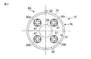
また、図3は、スコープ部8A側の連結端部16の端面、図4は、駆動源ユニット8B側の連結端部18の端面をそれぞれ示す。スコープ部8A側の連結端部16の端面には、湾曲部10を湾曲操作する湾曲操作方向、例えば、上下左右の4方向にそれぞれ対応する4つの受動カップリング部30a,30b,30c,30dが配設されている。ここで、受動カップリング部30a,30bは、湾曲部10を上下方向に湾曲操作する湾曲操作方向に対応し、受動カップリング部30c,30dは、湾曲部10を左右方向に湾曲操作する湾曲操作方向に対応する。 3 shows the end face of the connecting
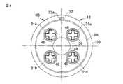
さらに、駆動源ユニット8B側の連結端部18の端面には、湾曲部10を湾曲操作する湾曲操作方向、例えば、上下左右の4方向にそれぞれ対応する4つの駆動カップリング31a,31b,31c,31dが配設されている。ここで、駆動カップリング31a,31bは、湾曲部10を上下方向に湾曲操作する湾曲操作方向に対応し、駆動カップリング31c,31dは、湾曲部10を左右方向に湾曲操作する湾曲操作方向に対応する。これら4つの駆動カップリング31a,31b,31c,31dは、4つの受動カップリング部30a,30b,30c,30dと対応する位置にそれぞれ配置されている。 Furthermore, on the end surface of the connecting
また、スコープ部8A側の連結端部16には太径部15の基端部外周面に着脱機構用の係合ピン32が突設されている。さらに、駆動源ユニット8Bの連結端部18には、スコープ部8A側の連結端部16と係脱可能に連結されるロックリング33が設けられている。このロックリング33は、駆動源ユニット8Bの連結端部18に軸回り方向に回動可能に支持されている。 Further, an engaging
また、ロックリング33の内周面には、スコープ部8A側の連結端部16の係合ピン32と係脱可能に係合する例えばカム溝33aが形成されている。そして、スコープ部8Aと駆動源ユニット8Bとの連結時にはスコープ部8A側の連結端部16と駆動源ユニット8Bの連結端部18とが突き合わされる。このとき、スコープ部8A側の係合ピン32が駆動源ユニット8Bのカム溝33aに挿入される状態で係合される。この状態で、ロックリング33を所望の回転角回転させることにより、係合ピン32がカム溝33aの終端のロック位置に移動され、スコープ部8Aと駆動源ユニット8Bとが連結状態でロックされるようになっている。 Further, on the inner peripheral surface of the
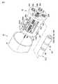
また、図5は、駆動源ユニット8Bに内蔵された駆動力発生手段19を構成する上下左右の4方向の駆動モータ19a,19b,19c,19dのうちの1つの駆動モータ19aを組み付けたモータ組み付けユニット(動作手段)34を示す。なお、湾曲部10を上下左右の4方向に湾曲操作する4方向の各駆動モータ19a,19b,19c,19dのモータ組み付けユニット34はいずれも同一構成になっている。そのため、ここでは、駆動モータ19aのモータ組み付けユニット34の構成のみを説明し、他の駆動モータ19b,19c,19dのモータ組み付けユニット34の説明は省略する。 Further, FIG. 5 shows a motor assembly in which one
駆動モータ19aのモータ組み付けユニット34は、駆動カップリング(連結部)31aと、ユニバーサルジョイント35と、モータユニット36とにより構成されている。モータユニット36には、例えば遊星歯車による減速機構が内蔵されている。このモータユニット36の出力軸36aは、ユニバーサルジョイント35を介して駆動カップリング31aに連結されている。ユニバーサルジョイント35は、駆動カップリング31aと受動カップリング部30aとの連結時に両者の軸ずれを吸収する機能を有する。 The
駆動カップリング31aは、駆動カップリング軸(駆動軸体)37と、駆動カップリング筒38とを有する。図5に示すように駆動カップリング軸37の基端部は、ユニバーサルジョイント35の出力軸35aの先端に固定されている。この駆動カップリング軸37の先端部には図6(A),(B)に示すようにほぼ十字形状の十字形状連結部39が形成されている。 The
さらに、駆動カップリング軸37の基端部には、ユニバーサルジョイント35の出力軸35aとの固定部の近傍に雄ねじ部40が形成されている。この雄ねじ部40にはほぼ円筒状の第1のばね押さえ41が螺着されている。第1のばね押さえ41の基端部外周面にはフランジ状のばね受け部41aが形成されている。 Further, a
また、図5に示すように駆動カップリング筒38の筒内には、駆動カップリング軸37の十字形状連結部39と嵌合する嵌合溝42が形成されている。この駆動カップリング筒38の嵌合溝42は、駆動カップリング軸37の十字形状連結部39とほぼ相似形状で、駆動カップリング軸37の十字形状連結部39に対し若干大きく形成されている。これにより、駆動カップリング筒38の嵌合溝42と駆動カップリング軸37の十字形状連結部39との連結時に、駆動カップリング筒38の嵌合溝42と駆動カップリング軸37の十字形状連結部39との間に若干の隙間が形成されている。そのため、駆動カップリング筒38と駆動カップリング軸37との連結時には、駆動カップリング筒38の嵌合溝42と駆動カップリング軸37の十字形状連結部39との嵌合部に沿って軸方向に摺動可能に、且つ回転駆動力が伝達できるように、両者が連結されている。 Further, as shown in FIG. 5, a
さらに、駆動カップリング筒38の基端部側の筒内には、円形状のねじ穴部43が形成されている。このねじ穴部43には円筒状の第2のばね押さえ44が螺着されて固定されている。第2のばね押さえ44の先端部外周面には内方に向けて突設されたフランジ状のばね受け部44aが形成されている。 Further, a
また、駆動カップリング筒38と、駆動カップリング軸37との間には、駆動カップリング筒38を先端側(受動カップリング部30a)の方向に付勢するコイルばね状の付勢ばね45が介設されている。この付勢ばね45は、駆動カップリング軸37の雄ねじ部40に螺着された第1のばね押さえ41によって第2のばね押さえ44のばね受け部44aとの間に挟み込むようにして固定されている。 In addition, a coil spring-
また、駆動カップリング筒38の先端部には、図4に示すように十字形状の凹陥部によって十字凹部46が形成されている。この十字凹部46は、後述する受動カップリング部30aの十字凸部47(図3参照)とほぼ相似形状で、受動カップリング部30aの十字凸部47に対し若干大きく形成されている。これにより、駆動カップリング31aの十字凹部46と受動カップリング部30aの十字凸部47との連結時に、駆動カップリング31aの十字凹部46と受動カップリング部30aの十字凸部47との間に若干の隙間が形成されている。そして、駆動カップリング31aと受動カップリング部30aとの連結時には、受動カップリング部30aの十字凸部47が駆動カップリング31aの十字凹部46内に挿入される状態で係脱可能に係合し、駆動力を伝達するようになっている。 Further, as shown in FIG. 4, a
なお、常時は付勢ばね45のばね力によって駆動カップリング筒38の第2のばね押さえ44のばね受け部44aの端面が、駆動カップリング軸37の十字形状連結部39の端面と当接している状態で保持されるため、駆動カップリング筒38は図5の通常状態より駆動モータ19a側には移動しない。しかし、駆動カップリング31aと受動カップリング部30aとの接続時にお互いの十字凸部47、十字凹部46との位置が一致していない場合には、駆動カップリング31aがいったん駆動モータ19a側に退避した状態で、スコープ部8A側の連結端部16と駆動源ユニット8Bの連結端部18とが接続され、その後の駆動モータ19aの回転により十字凸部47と十字凹部46との位置が合った時、付勢ばね45により駆動カップリング筒38が受動カップリング部30aの方向に押し出され両者が接続されることになる。 Note that the end surface of the
また、駆動源ユニット8Bのユニット本体17の先端部には、ロックリング33の内部側に上記構成の4つの駆動カップリング31a,31b,31c,31dが周方向に沿って等間隔に配置されている。さらに、ユニット本体17の先端部の端面には4つの駆動カップリング31a,31b,31c,31dの内側に円孔48が形成されている。この円孔48内には挿入部7に内蔵されるライトガイドファイバー13と、CCDケーブル21と、送水管路113と、送気管路114と、吸引管路118などが配設されている。 Further, the four
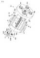
また、図7は、スコープ部8Aの太径部15の内部構成を示す。このスコープ部8Aの太径部15には、円筒状のカバー51と、このカバー51内に挿入された状態で装着されたワイヤ操作部52とが設けられている。このワイヤ操作部52は、駆動源ユニット8B側から供給される湾曲部10の駆動力を湾曲操作用のワイヤ14の牽引力として伝達する動力伝達手段を構成するものである。 FIG. 7 shows the internal configuration of the large-
図8は、ワイヤ操作部52の分解斜視図を示す。このワイヤ操作部52には、着脱可能に連結される2つ(第1,第2)のフレーム部材53,54が設けられている。第1のフレーム部材53には、円板状の端板53aと、後部リング53bと、アーム状の複数、本実施の形態では4つの連結フレーム(梁部)53cとが設けられている。円板状の端板53aと、後部リング53bとは中心線方向に離間対向配置され、4つの連結フレーム53cは、円板状の端板53aと、後部リング53bとの間に配置されている。 FIG. 8 is an exploded perspective view of the
また、第2のフレーム部材54には、円板状の端板54aと、円筒状の連結リング54bとが設けられている。そして、第2のフレーム部材54の連結リング54bに第1のフレーム部材53の後部リング53bが外嵌される状態で、第2のフレーム部材54が第1のフレーム部材53に連結されている。 The
さらに、第1のフレーム部材53の端板53aおよび第2のフレーム部材54の端板54aには中央に円孔55がそれぞれ形成されている。この円孔55内には挿入部7に内蔵されるライトガイドファイバー13と、CCDケーブル21と、送水管路113と、送気管路114と、吸引管路118などが挿通されている。 Further, a
また、ワイヤ操作部52の内部には、湾曲部10を湾曲操作する湾曲方向とそれぞれ対応した数(本実施の形態では4方向湾曲なので4本)のリードねじ(ねじ部材)56a,56b,56c,56dが設けられている。ここで、第1のフレーム部材53の端板53aには、円孔55の周囲に4つの第1のリードねじ軸受57a,57b,57c,57d(図8中に1つの第1のリードねじ軸受57aのみを図示する)が設けられている。これら4つの第1のリードねじ軸受57a,57b,57c,57dは駆動源ユニット8Bの駆動カップリング31a,31b,31c,31dと対応する位置に配置されている。同様に、第2のフレーム部材54の端板54aには、円孔55の周囲に4つの第2のリードねじ軸受58a,58b,58c,58d(図8中に2つの第2のリードねじ軸受58a,58bのみを図示する)が設けられている。 In addition, inside the
また、各リードねじ56a〜56dの一端部(駆動源ユニット8B側の端部)は、第1のフレーム部材53の第1のリードねじ軸受57a,57b,57c,57dから端板53aの外部側に延出され、この延出端部にそれぞれ受動カップリング部30a,30b,30c,30dが設けられている。 Further, one end portion (end portion on the
さらに、各リードねじ56a〜56dの他端部(挿入部7側の端部)には、ねじ部56a1,56b1,56c1,56d1よりも細径の細径部56a2,56b2,56c2,56d2がそれぞれ形成されている。そして、各リードねじ56a〜56dの細径部56a2〜56d2は、第2のフレーム部材54の第2のリードねじ軸受58a〜58dから端板54aを貫通し、端板54aの外部側に延出されている。この延出端部にはそれぞれ駆動源ユニット8B側に抜けないようワッシャ59を介してEリング60がはめ込まれている。これにより、4本のリードねじ56a,56b,56c,56dは、第1のリードねじ軸受57a,57b,57c,57dと、第2のリードねじ軸受58a,58b,58c,58dとによってそれぞれ軸回り方向に回転自在に軸支されている。 Further, the other end portions (end portions on the
また、各リードねじ56a〜56dの細径部56a2〜56d2には、各リードねじ56a〜56dを駆動源ユニット8B側に付勢するためのコイルばね(付勢部材)61が巻装されている。そして、各リードねじ56a〜56dは、コイルばね61のばね力によって駆動源ユニット8B側に押圧される方向に付勢されている。 Further, coil springs (biasing members) 61 for urging the lead screws 56a to 56d toward the
また、ワイヤ操作部52には、各リードねじ56a〜56dの回転にともない各リードねじ56a〜56dの軸方向に移動する4つのナット部材(応動部材)62a,62b,62c,62dが設けられている。各ナット部材62a〜62dには、各リードねじ56a〜56dのねじ部56a1〜56d1と螺合するねじ穴部62a1,62b1,62c1,62d1と、ワイヤ14の基端部に接続されるワイヤ接続部62a2,62b2,62c2,62d2とを有する。 The
さらに、各ナット部材62a〜62dの端部には、U字溝62a3,62b3,62c3,62d3がそれぞれ形成されている。これらのU字溝62a3〜62d3には、各リードねじ56a〜56dの中心線方向と平行に配設された4つの回転規制軸63がそれぞれ挿入状態で係合されている。そして、各ナット部材62a〜62dはU字溝62a3〜62d3と回転規制軸63との係合部に沿って軸方向に摺動可能に支持されている。これにより、各ナット部材62a〜62dが各リードねじ56a〜56dの回転に従い各リードねじ56a〜56dの軸方向に進退する際に、4つの回転規制軸63によって各ナット部材62a〜62dがリードねじ56a〜56dを中心として回転することを規制するようになっている。 Furthermore, U-shaped grooves 62a3, 62b3, 62c3 and 62d3 are formed at the ends of the
各ナット部材62a〜62dのワイヤ接続部62a2〜62d2には、ワイヤ14を保持するためのスリット部62a4,62b4,62c4,62d4が設けられている。また、ワイヤ14の駆動源ユニット8B側の端部には、ワイヤピン66がロー付け等により固定されている。そして、各ナット部材62a〜62dのスリット部62a4〜62d4にワイヤ14を挿入し、ワイヤ押さえ67を各ナット部材62a〜62dに接着等で固定することにより、ワイヤ14の基端部が各ナット部材62a〜62dに組み付けられる。これにより、各ナット部材62a〜62dが駆動源ユニット8B側に移動する時はワイヤピン66が各ナット部材62a〜62dの端面と接し、ワイヤ14を引っ張り、湾曲部10の湾曲操作を行うようになっている。 The wire connecting portions 62a2 to 62d2 of the
また、各ナット部材62a〜62dのスリット部62a4〜62d4のスリット幅はワイヤ14の外径より若干大きく設定されている。これにより、各ナット部材62a〜62dが挿入部7の方向に移動した場合には、各ナット部材62a〜62dのスリット部62a4〜62d4とワイヤ14との間の隙間によってワイヤ14の弛みを吸収できるようになっている。 Further, the slit widths of the slit portions 62a4 to 62d4 of the
次に、上記構成の作用について説明する。本実施の形態の着脱式の内視鏡1の使用時にはスコープ部8Aと駆動源ユニット8Bとが連結されて使用される。このスコープ部8Aと駆動源ユニット8Bとの連結作業時にはスコープ部8A側の連結端部16と駆動源ユニット8Bの連結端部18とが突き合わされる。そして、スコープ部8A側の連結端部16の端面の4つの受動カップリング部30a,30b,30c,30dと、駆動源ユニット8B側の連結端部18の端面の4つの駆動カップリング31a,31b,31c,31dとが係脱可能に係合される状態にセットされる。 Next, the operation of the above configuration will be described. When the
また、スコープ部8A側の受動カップリング部30a〜30dと、駆動源ユニット8B側の駆動カップリング31a〜31dとの連結時には、受動カップリング部30aの十字凸部47が駆動カップリング31aの十字凹部46内に挿入される状態で係脱可能に係合される。このとき、スコープ部8A側の受動カップリング部30a〜30dと、駆動源ユニット8B側の駆動カップリング31a〜31dとの連結作業中に、お互いの十字凸部47と、十字凹部46との位置が一致していない場合には、十字凹部46の周縁部位に十字凸部47が突き当たり、例えば、駆動カップリング31aがいったん駆動モータ19a側に退避する。この状態で、スコープ部8A側の連結端部16と駆動源ユニット8Bの連結端部18とが接続される。その後、駆動モータ19aの回転により十字凸部47と十字凹部46との位置が合った時、付勢ばね45により駆動カップリング筒38が受動カップリング部30aの方向に押し出され両者が接続される。これにより、駆動源ユニット8Bの駆動モータ19aの駆動力が駆動カップリング31aと受動カップリング部30aとの係合部を介してスコープ部8A側に伝達可能になる。 Further, when the
さらに、スコープ部8A側のライトガイドファイバー13と、CCDケーブル21と、送水管路113と、送気管路114と、吸引管路118などの各接続端部と、駆動源ユニット8B側のライトガイドファイバー13と、CCDケーブル21と、送水管路113と、送気管路114と、吸引管路118などの各接続端部とがそれぞれ着脱可能に接続される。 Further, the
また、スコープ部8Aと駆動源ユニット8Bとの連結時には、スコープ部8A側の係合ピン32が駆動源ユニット8Bのカム溝33aに挿入される状態で係合される。この状態で、ロックリング33を所望の回転角回転させることにより、係合ピン32がカム溝33aの終端のロック位置に移動され、スコープ部8Aと駆動源ユニット8Bとが連結状態でロックされる。 Further, when the
なお、スコープ部8Aと駆動源ユニット8Bとの連結時の初期状態では、図2に示すようにスコープ部8Aの湾曲部10は湾曲していないほぼ真っ直ぐな直線形状で保持されている。このとき、ワイヤ操作部52のナット部材62a,62b,62c,62dは各リードねじ56a〜56dの回転による移動範囲のほぼ中央位置に配置された定位置で保持されている。 In the initial state when the
このようにスコープ部8Aと駆動源ユニット8Bとの連結作業が終了し、スコープ部8Aと駆動源ユニット8Bとが組み付けられた状態で、内視鏡1が使用される。この内視鏡1の使用時には、操作部6のハンドピース28を操作することにより内視鏡1の動きが制御される。すなわち、ハンドピース28のジョイスティック29aを操作することにより、湾曲部10が遠隔的に湾曲操作される。さらに、リモートスイッチ29bを操作することにより、各リモートスイッチ29bの機能に対応する内視鏡操作が行われる。 Thus, the
また、湾曲部10の湾曲操作時にはハンドピース28のジョイスティック29aが所望の操作方向に傾動操作される。このジョイスティック29aの傾動操作に応じて発生する信号がモーターコントロールユニット5に入力される。さらに、ジョイスティック29aの傾動操作時には、ジョイスティック29aの傾動操作に応じた制御信号がモーターコントロールユニット5から出力され、駆動源ユニット8B内の上下湾曲操作用の駆動モータ19a,19bおよび左右湾曲操作用の駆動モータ19c,19dのうち少なくともいずれかが駆動される。 In addition, when the bending
ここで、例えばジョイスティック29aが上下湾曲操作方向に傾動操作された場合には、上下湾曲操作用の駆動モータ19a,19bが駆動される。このとき、2つの駆動モータ19a,19bは、例えば互いに逆回り方向に回転駆動される。そして、上下湾曲操作用の一方の駆動モータ19aの出力軸36aの回転がユニバーサルジョイント35を介して駆動カップリング31aに伝達される。さらに、この駆動カップリング31aと受動カップリング部30aとの嵌合部を介してリードねじ56aが軸回り方向に回転駆動される。 Here, for example, when the
このリードねじ56aの軸回り方向の回転にともない、ナット部材62aが軸方向に送り駆動される。このとき、ナット部材62aは、回転規制軸63によってリードねじ56aを中心として回転することが規制される。そして、リードねじ56aの回転に従いナット部材62aがリードねじ56aの軸方向に進退する。 As the
また、上述したとおり、一方の駆動モータ19aの出力軸36aの回転時には、他方の駆動モータ19bの出力軸36aが逆回り方向に回転駆動される。そして、駆動モータ19bの出力軸36aの回転がユニバーサルジョイント35を介して駆動カップリング31bに伝達される。さらに、この駆動カップリング31bと受動カップリング部30bとの嵌合部を介してリードねじ56bがリードねじ56aと逆回り方向に回転駆動される。このリードねじ56bの逆回り方向の回転にともない、ナット部材62bがナット部材62aとは反対方向に向けて軸方向に送り駆動される。これにより、2つのナット部材62a,62bは、それぞれ逆方向に等距離、進退動作する。 As described above, when the
例えば、一方のナット部材62aがスコープ部8A側に向けて一定距離、前進動作し、他方のナット部材62bが駆動源ユニット8B側に向けてナット部材62aの前進距離と等距離、後退動作する。このとき、駆動源ユニット8B側に移動する一方のナット部材62b(または62a)によってワイヤ14が牽引操作される。これにより、駆動源ユニット8B側に牽引操作されるワイヤ14によって湾曲部10が上下方向に湾曲操作される。 For example, one
なお、左右湾曲操作用の駆動モータ19c,19dの駆動時にも上下湾曲操作の場合とほぼ同様に左右湾曲操作用の2つの駆動モータ19c,19dが、互いに逆回り方向に回転駆動される。 When driving the left and right bending
そして、左右湾曲操作用の一方の駆動モータ19cの出力軸36aの回転がユニバーサルジョイント35を介して駆動カップリング31cに伝達される。さらに、この駆動カップリング31cと受動カップリング部30cとの嵌合部を介してリードねじ56cが軸回り方向に回転駆動される。 Then, the rotation of the
また、駆動モータ19cの出力軸36aの回転時には、他方の駆動モータ19dの出力軸36aが逆回り方向に回転駆動される。そして、駆動モータ19dの出力軸36aの回転がユニバーサルジョイント35を介して駆動カップリング31dに伝達される。さらに、この駆動カップリング31dと受動カップリング部30dとの嵌合部を介してリードねじ56dがリードねじ56cと逆回り方向に回転駆動される。このリードねじ56dの逆回り方向の回転にともない、ナット部材62dがナット部材62cとは反対方向に向けて軸方向に送り駆動される。これにより、2つのナット部材62c,62dは、それぞれ逆方向に等距離、進退動作する。 Further, when the
例えば、一方のナット部材62cがスコープ部8A側に向けて一定距離、前進動作し、他方のナット部材62dが駆動源ユニット8B側に向けてナット部材62cの前進距離と等距離、後退動作する。このとき、駆動源ユニット8B側に移動する一方のナット部材62d(または62c)によってワイヤ14が牽引操作される。これにより、駆動源ユニット8B側に牽引操作されるワイヤ14によって湾曲部10が左右方向に湾曲操作される。 For example, one
そして、上記湾曲部10の上下方向の湾曲操作と、左右方向の湾曲操作とが組み合わされてスコープ部8Aの挿入部7の先端構成部11を所望の方向に湾曲させることができる。 The distal
そこで、上記構成のものにあっては次の効果を奏する。すなわち、本実施の形態では、体腔内に挿入可能な細長い挿入部7を備えたスコープ部8Aと、駆動源ユニット8Bとが着脱可能に連結される着脱式内視鏡1を設けている。ここで、スコープ部8A側のワイヤ操作部52にリードねじ56a,56b,56c,56dと、各リードねじ56a〜56dと螺合するナット部材62a,62b,62c,62dとを設け、各リードねじ56a〜56dに上下左右の4方向にそれぞれ対応する4つの受動カップリング部30a,30b,30c,30dを設けている。また、駆動源ユニット8Bには、駆動力発生手段19の4つの駆動モータ19a,19b,19c,19dと、駆動力発生手段19の各駆動モータ19a〜19dからの駆動力によって軸回り方向に回転駆動される駆動カップリング軸37と、駆動カップリング31a,31b,31c,31dとを設けている。そして、駆動源ユニット8Bとワイヤ操作部52との連結時には駆動力発生手段19の各駆動モータ19a〜19dからの駆動力を駆動カップリング31a,31b,31c,31dを介して受動カップリング部30a,30b,30c,30dに伝達してリードねじ56a〜56dを軸回り方向に回転駆動させる。これにより、ナット部材62a,62b,62c,62dを軸方向に移動させ、駆動源ユニット8B側に移動するナット部材62a(または62b)、62c(または62d)によってワイヤ14を牽引操作することにより、湾曲部10が上下方向、或いは左右方向に湾曲操作させるようにしている。このように本実施の形態では、湾曲部10を湾曲操作するための駆動機構としてリードねじ方式の駆動機構を使用しているので、歯車列による減速機構に比べ簡単な構成で高い減速比が得られる。その結果、駆動側減速機構の小型化が容易で、装置全体としての小型化に寄与できるという効果がある。 Therefore, the above configuration has the following effects. That is, in the present embodiment, the
さらに、本実施の形態のスコープ部8Aと駆動源ユニット8Bとの駆動力の伝達部は同軸接続であり、且つ駆動カップリング31a,31b,31c,31dが各駆動モータ19a〜19dの方向に退避可能な構成となっている。そのため、駆動カップリング31aと受動カップリング部30aとの接続時にお互いの十字凸部47、十字凹部46との位置が一致していない場合には、駆動カップリング31aがいったん駆動モータ19a側に退避した状態で、スコープ部8A側の連結端部16と駆動源ユニット8Bの連結端部18とが接続され、その後の駆動モータ19aの回転により十字凸部47と十字凹部46との位置が合った時、付勢ばね45により駆動カップリング筒38が受動カップリング部30aの方向に押し出されて両者が接続されるようになっている。その結果、駆動カップリング31a,31b,31c,31dの十字凹部46と、受動カップリング部30a,30b,30c,30dの十字凸部47との位置合わせを意識せずに駆動源ユニット8Bの連結端部18と、スコープ部8A側の連結端部16とを容易に接続することができる効果がある。 Further, the driving force transmitting portion between the
したがって、本実施の形態では、従来に比べて内視鏡1のスコープ部8Aと駆動源ユニット8Bとの連結部を小型化することができ、スコープ部8Aと駆動源ユニット8Bとの連結部との着脱を容易に行うことができる。 Therefore, in the present embodiment, the connecting portion between the
さらに、本実施の形態では、湾曲部10を湾曲操作するための駆動機構としてリードねじ56a,56b,56c,56dを用いていることから、湾曲操作により先端部を所望の方向に湾曲させた後、湾曲駆動手段への通電を停止しても、湾曲形状が維持される。そのため、操作し易い構成となるばかりか、湾曲部10の湾曲を保持するための電力が不要であることから経済的でもある。 Further, in the present embodiment, since the lead screws 56a, 56b, 56c, and 56d are used as a drive mechanism for bending the bending
また、図9乃至図11は本発明の第2の実施の形態を示すものである。本実施の形態は第1の実施の形態(図1乃至図8参照)の着脱式内視鏡1のスコープ部8Aの太径部15の内部に組み込まれているワイヤ操作部52に各ナット部材62a〜62dの位置を検出する位置検出手段71を設けたものである。なお、これ以外の部分は第1の実施の形態の着脱式内視鏡1と同一構成になっており、第1の実施の形態の着脱式内視鏡1と同一部分には同一の符号を付してここではその説明を省略する。 9 to 11 show a second embodiment of the present invention. In this embodiment, each nut member is attached to the
各ナット部材62a〜62dの位置検出手段71は次のとおり構成されている。すなわち、図10に示すように各ナット部材62a〜62dのU字溝62a3〜62d3の近傍には、例えばアルミ箔テープ等による反射部材72が設けられている。この反射部材72は、第1のフレーム部材53の連結フレーム53cと対向する面に配置されている。 The position detection means 71 of each
さらに、第1のフレーム部材53の連結フレーム53cには、フォトリフレクタ取り付け孔73が形成されている。このフォトリフレクタ取り付け孔73には、フレキシブル基板等に接続されたフォトリフレクタ74が組み付けられている。なお、連結フレーム53cには、第1のフレーム部材53の中心線方向に沿って溝部75が延設されている。この溝部75には、フォトリフレクタ74の図示しない配線材(フレキシブル基板)が配線されている。 Further, a photo
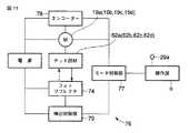
また、図11は、本実施の形態の着脱式内視鏡1のモーターコントロールユニット5に組み込まれた制御回路76を示す。この制御回路76には、操作部6に接続されたモータ制御部77が設けられている。このモータ制御部77には、各駆動モータ19a〜19dが接続されている。 FIG. 11 shows a
また、各駆動モータ19a〜19dには、回転角度を検出するエンコーダ78がそれぞれ設けられている。さらに、各ナット部材62a〜62dの位置を検出するフォトリフレクタ74は、検出制御部79に接続されている。各駆動モータ19a〜19dのエンコーダ78と、フォトリフレクタ74の検出制御部79とは、それぞれモータ制御部77に接続されている。 Each of the
そして、各ナット部材62a〜62dの動作時には、エンコーダ78によって各駆動モータ19a〜19dの回転角度が検出される。さらに、各ナット部材62a〜62dが連結フレーム53cのフォトリフレクタ74と対応する位置を通る際にフォトリフレクタ74から出射される光が反射部材72によって反射され、各ナット部材62a〜62dの位置、例えば湾曲部10の湾曲角度が0°のニュートラル位置などの初期位置を検出することができる。このフォトリフレクタ74からの検出信号は、検出制御部79に入力された後、モータ制御部77に出力される。これにより、モータ制御部77によって湾曲部10の湾曲角度が高精度に制御される。 When the
そこで、本実施の形態でも、第1の実施の形態と同様に、湾曲部10を湾曲操作するための駆動機構としてリードねじ方式の駆動機構を使用しているので、歯車列による減速機構に比べ簡単な構成で高い減速比が得られる。その結果、駆動側減速機構の小型化が容易で、装置全体としての小型化に寄与できるという効果があり、従来に比べて内視鏡1のスコープ部8Aと駆動源ユニット8Bとの連結部を小型化することができ、スコープ部8Aと駆動源ユニット8Bとの連結部との着脱を容易に行うことができる。 Therefore, in the present embodiment as well, as in the first embodiment, a lead screw type driving mechanism is used as a driving mechanism for bending the bending
さらに、本実施の形態では、ワイヤ操作部52に各ナット部材62a〜62dの位置を検出する位置検出手段71を設けたので、モータ制御部77によって湾曲部10の湾曲角度を高精度に制御できる効果がある。 Furthermore, in the present embodiment, since the position detecting means 71 for detecting the positions of the
また、図12は本発明の第3の実施の形態を示すものである。第2の実施の形態(図9乃至図11参照)では、ワイヤ操作部52に各ナット部材62a〜62dの位置を検出する位置検出手段71としてナット部材62a〜62dの反射部材72の位置を検知するフォトリフレクタ74を設けた構成を示したが、本実施の形態は第2の実施の形態とは異なる構成の位置検出手段71を設けたものである。 FIG. 12 shows a third embodiment of the present invention. In the second embodiment (see FIGS. 9 to 11), the position of the reflecting member 72 of the
すなわち、本実施の形態では、第1のフレーム部材53の連結フレーム53cに、図12に示すように発光部81aと受光部81bとを有するフォトインタラプタ81を設けている。さらに、ナット部材62a〜62dには、フォトインタラプタ81の発光部81aと受光部81bとの間を横切るように配置される突起部82が設けられている。 In other words, in the present embodiment, the
そして、各ナット部材62a〜62dの動作時には、各ナット部材62a〜62dの突起部82が連結フレーム53cのフォトインタラプタ81の発光部81aと受光部81bとの間を横切る際にフォトインタラプタ81の発光部81aと受光部81bとの間の光を遮断することにより、各ナット部材62a〜62dの位置、例えば湾曲部10の湾曲角度が0°のニュートラル位置などの初期位置を検出することができる。そのため、本実施の形態でも第2の実施の形態と同様に、モータ制御部77によって湾曲部10の湾曲角度を高精度に制御できる効果がある。 When the
また、図13は本発明の第4の実施の形態を示すものである。本実施の形態は第1の実施の形態(図1乃至図8参照)の着脱式内視鏡1のスコープ部8Aの太径部15の内部に組み込まれているワイヤ操作部52の構成を次の通り変更したものである。なお、これ以外の部分は第1の実施の形態の着脱式内視鏡1と同一構成になっており、第1の実施の形態の着脱式内視鏡1と同一部分には同一の符号を付してここではその説明を省略する。 FIG. 13 shows a fourth embodiment of the present invention. The present embodiment follows the configuration of the
すなわち、第1の実施の形態のワイヤ操作部52では、スコープ部8A側の連結端部16の端面に上下左右の4方向の湾曲方向に対応する4つの受動カップリング部30a,30b,30c,30dを設けるとともに、駆動源ユニット8Bに上下左右の4方向に湾曲操作する4方向の駆動モータ19a,19b,19c,19dをそれぞれ設けた構成を示した。これに対し、本実施の形態のワイヤ操作部52では、スコープ部8A側の連結端部16の端面に上下方向の湾曲方向に1つの受動カップリング部91aのみを設け、左右方向の湾曲方向にも1つの受動カップリング部91bのみを設けるとともに、駆動源ユニット8Bにも上下方向の湾曲方向に1つの駆動モータ92aのみを設け、左右方向の湾曲方向にも1つの駆動モータ92bのみを設ける構成にしたものである。 That is, in the
さらに、本実施の形態のワイヤ操作部52では、上下方向の受動カップリング部91aに駆動ギヤ93a、左右方向の受動カップリング部91bにも駆動ギヤ93bをそれぞれ設けている。 Furthermore, in the
また、4つのリードねじ56a〜56dには、駆動源ユニット8B側の端部にギヤ94a〜94dをそれぞれ設けている。ここで、4つのリードねじ56a〜56dのうち、上下方向の湾曲操作用のリードねじ56a,56bのギヤ94a,94bは、上下方向の受動カップリング部91aの駆動ギヤ93aと噛合され、左右方向の湾曲操作用のリードねじ56c,56dのギヤ94c,94dは、左右方向の受動カップリング部91bの駆動ギヤ93bと噛合されている。なお、上方向、及び下方向用のリードねじ56a,56bは、互いに逆方向(例えば、上方向のリードねじ56aは右ネジ、下方向のリードねじ56bは左ネジ)に切っておく。左右方向についても同様に、左方向のリードねじ56cは右ネジ、右方向のリードねじ56dは左ネジで構成する。 The four
さらに、駆動源ユニット8Bには、上下方向の湾曲方向の駆動モータ92aの駆動カップリング95aと、左右方向の湾曲方向の駆動モータ92bの駆動カップリング95bとを設けている。そして、スコープ部8Aの連結端部16と、駆動源ユニット8B側の連結端部18との連結時には、上下方向の湾曲方向の駆動カップリング95aと、上下方向の受動カップリング部91aとを連結させ、左右方向の駆動カップリング95bと、左右方向の受動カップリング部91bとを連結させる。これにより、上下方向の湾曲操作および左右方向の湾曲操作をそれぞれ1つの駆動源(駆動モータ92a,92b)で駆動力を伝達することができる。そのため、上下左右の4方向の湾曲を操作する場合でも2つの駆動源(駆動モータ92a,92b)で行うことができるので、小型化に寄与できる。 Further, the
そこで、本実施の形態では、第1の実施の形態に比べて部品点数を少なくすることができ、より簡単な構成で安価な着脱式内視鏡1のスコープ部8Aを提供することができる効果がある。 Therefore, in this embodiment, the number of parts can be reduced as compared with the first embodiment, and the
なお、本発明は上記実施の形態に限定されるものではない。例えば、上記各実施の形態では4方向湾曲を例として説明してきたが、2方向湾曲の内視鏡についても同様であることは言うまでもない。さらに、第1の実施の形態のスコープ部8Aの挿入部7の内部の処置具挿通管路112と、送水管路113と、送気管路114などの管路類を省略してもよい。 The present invention is not limited to the above embodiment. For example, in each of the above-described embodiments, the four-direction bending has been described as an example, but it goes without saying that the same applies to a two-direction bending endoscope. Furthermore, the treatment
また、上記各実施の形態では駆動カップリング31aの十字凹部46と受動カップリング部30aの十字凸部47とを連結させる構成を示したが、図14(A)に示す第1の変形例のように受動カップリング部30a〜30dにほぼY字状のY字凸部101や、図14(B)に示す第2の変形例のように十字凸部を2つ組み合わせた多角形状凸部102などの非円形状の係合突部を設け、駆動カップリング31aにY字凸部101や、多角形状凸部102とほぼ相似形状の係合凹部を設ける構成にしても良い。さらに、その他、本発明の要旨を逸脱しない範囲で種々変形実施できることは勿論である。 In each of the above embodiments, the configuration in which the
次に、本出願の他の特徴的な技術事項を下記の通り付記する。
記
(付記項1) 湾曲操作を行うための操作部と、先端部、湾曲部、硬性、又は軟性の挿入部、及び操作部との連結部を含むスコープ部とを着脱可能な内視鏡装置において、連結部内には細長のネジ部材と、ネジ部材と螺合するナット部材が設けられ、ネジ部材の回動に従いナット部材のネジ部材軸方向の進退動作と連動して、ナットに取り付けられ他方が湾曲部に取り付けられている湾曲ワイヤを進退させ湾曲操作を行うことを特徴とする内視鏡装置。Next, other characteristic technical matters of the present application are appended as follows.
Record
(Additional Item 1) In an endoscope apparatus in which an operation part for performing a bending operation and a scope part including a tip part, a bending part, a rigid or soft insertion part, and a connection part with the operation part are detachable In the connecting portion, an elongated screw member and a nut member screwed with the screw member are provided, and the other attached to the nut is interlocked with the forward and backward movement of the nut member in the axial direction of the screw member as the screw member rotates. An endoscope apparatus that performs a bending operation by moving a bending wire attached to a bending portion forward and backward.
(付記項2) ネジ部材の操作部側端部には、連結部から露出して設けられた受動カップリング部を有し、操作部に設けられ操作部内の駆動源と連動回転する駆動カップリング部と軸方向で係合し駆動力が伝達されることを特徴とする、付記項1に記載の内視鏡装置。 (Additional Item 2) A drive coupling that has a passive coupling portion that is exposed from the coupling portion and is provided on the operation portion side end of the screw member and rotates in conjunction with a drive source in the operation portion. The endoscope apparatus according to
(付記項3) 駆動カップリング部は、軸方向に進退可能に付勢されていることを特徴とする、付記項1に記載の内視鏡装置。 (Additional Item 3) The endoscope apparatus according to
(付記項4) ネジ部材は、軸方向に進退可能に付勢されていることを特徴とする、付記項1に記載の内視鏡装置。 (Additional Item 4) The endoscope apparatus according to
(付記項5) 湾曲ワイヤは、ナット部材に対しナット部材の進退方向に移動可能に支持されていることを特徴とする、付記項1に記載の内視鏡装置。 (Additional Item 5) The endoscope apparatus according to
(付記項6) 連結部には、ナット部材の位置を検知する位置検知手段が設けられていることを特徴とする、付記項1に記載の内視鏡装置。 (Additional Item 6) The endoscope apparatus according to
(付記項7) 前記位置検知手段は、ナット部材に設けられた反射部材の位置を検知するフォトリフレクタであることを樹敷とする、付記項6に記載の内視鏡装置。 (Additional Item 7) The endoscope apparatus according to
(付記項8) 前記位置検知手段は、ナット部材に設けられた突起の位置を検知するフォトインタラプタであることを特徴とする、付記項6に記載の内視鏡装置。 (Additional Item 8) The endoscope apparatus according to
(付記項9) 上下、及び又は、左右の湾曲を操作するためのネジ部材をそれぞれ1つの駆動源で駆動することを特徴とする、付記項1に記載の内視鏡装置。 (Additional Item 9) The endoscope apparatus according to
(付記項10) ネジ部材の操作部端面に連結部から露出して歯車部を有し、上下、及び又は、左右の歯車部と噛合するアイドラーに受動カップリングを設け、駆動源と連動回転する駆動カップリング部と係合し駆動力が伝達されることを特徴とする、付記項9に記載の内視鏡装置。 (Additional Item 10) A gear portion is exposed from the coupling portion on the end surface of the operation portion of the screw member, and a passive coupling is provided on the idler that meshes with the upper and lower and / or left and right gear portions, and rotates in conjunction with the drive source. The endoscope apparatus according to
(付記項11) 複数の湾曲駒を連結して構成する湾曲部を備え、体腔内に挿入可能な挿入部と、前記湾曲部に先端側を接続され、基端側に延出されたワイヤと、前記ワイヤの基端部に接続され、螺子部を備えた口金と、前記螺子部に螺合可能であるとともに.螺合量に応じて前記口金を進退させる回転体と、前記回転体を回転させる駆動源を備えると共に、前記回転体の基端側に配置された動作手段と、を具備することを特徴とする内視鏡。 (Additional Item 11) A bending portion that includes a plurality of bending pieces coupled to each other, an insertion portion that can be inserted into a body cavity, a wire that has a distal end connected to the bending portion, and extends to the proximal end side; And a base connected to the base end of the wire and provided with a screw part, and can be screwed into the screw part. A rotating body that moves the base back and forth according to the amount of screwing, and a drive source that rotates the rotating body, and an operating means that is arranged on the base end side of the rotating body are provided. Endoscope.
(付記項12) 複数の湾曲駒を連結して構成する湾曲部を備え、体腔内に挿入可能な挿入部と、前記挿入部の基端側に設けられた基部と、前記湾曲部に先端側を接続され、前記基部にかけて延出されたワイヤと、前記基部に設けられるとともに前記ワイヤの基端部に接続され、螺子部を備えた口金と、前記基部に設けられ、前記螺子部に螺合可能であるとともに、螺合量に応じて前記口金を進退させる回転体と、前記基部に対して着脱可能な本体部と、前記回転体を回転させる駆動源を備えると共に前記本体部に設けられ、前記回転体に着脱される動作手段と、を具備することを特徴とする内視鏡。 (Additional Item 12) Provided with a bending portion configured by connecting a plurality of bending pieces, an insertion portion that can be inserted into a body cavity, a base portion provided on a proximal end side of the insertion portion, and a distal side on the bending portion Are connected to the base, and are connected to the base end of the wire and provided with a screw part, and are provided on the base and screwed into the screw part. A rotating body that advances and retracts the base according to the amount of screwing, a main body that can be attached to and detached from the base, and a drive source that rotates the rotating body, and is provided in the main body. And an operating means that is attached to and detached from the rotating body.
(付記項13) 前記基部に設けられ、前記口金の進退を検知する検知手段を、具備することを特徴とする付記項11および12記載の内視鏡。 (Additional Item 13) The endoscope according to
本発明は、内視鏡の挿入部の先端側に配置された湾曲部を湾曲操作する駆動力発生手段が内蔵された駆動源ユニットが挿入部の基端部に着脱部を介して着脱可能に結合される駆動源ユニット着脱式の内視鏡を使用する技術分野や、その内視鏡を製造する技術分野に有効である。 According to the present invention, a drive source unit incorporating a driving force generating means for bending a bending portion disposed on the distal end side of an insertion portion of an endoscope can be attached to and detached from a proximal end portion of the insertion portion via an attachment / detachment portion. This is effective in a technical field that uses a combined drive source unit removable endoscope and a technical field that manufactures the endoscope.
7…挿入部、8A…スコープ部、8B…駆動源ユニット、10…湾曲部、14…ワイヤ、15…太径部(連結部)、19…駆動力発生手段、19a,19b,19c,19d…駆動モータ、31a,31b,31c,31d…駆動カップリング(連結部)、34…モータ組み付けユニット(動作手段)、37…駆動カップリング軸(駆動軸体)、52…ワイヤ操作部、56a,56b,56c,56d…リードねじ(ねじ部材)、62a,62b,62c,62d…螺進部材(応動部材)、62a1,62b1,62c1,62d1…ねじ穴部、62a2,62b2,62c2,62d2…ワイヤ接続部。 DESCRIPTION OF
Claims (3)
Translated fromJapanese前記挿入部の先端部側に配置され、複数の湾曲駒を連結して構成される湾曲部と、
先端側が前記湾曲部に接続され、基端部側が前記挿入部の基端部側に延出された前記湾曲部の湾曲操作用のワイヤと、
前記挿入部の基端側に設けられ、軸回り方向に回転自在に支持されたねじ部材と、このねじ部材と螺合するねじ穴部と前記ワイヤの基端部に接続されるワイヤ接続部とを有し、前記ねじ部材の回転にともない前記ねじ部材の軸方向に移動する応動部材とを備えたワイヤ操作部と、
このワイヤ操作部に着脱可能に連結され、前記湾曲部を湾曲させる駆動力を発生させる駆動力発生手段を有する駆動源ユニットと、
前記駆動源ユニットに設けられ、前記駆動力発生手段からの駆動力によって軸回り方向に回転駆動される駆動軸体と、前記駆動軸体の先端部に配置され、前記駆動源ユニットと前記ワイヤ操作部との連結時に前記ねじ部材の基端部に着脱可能に連結される連結部とを有し、前記駆動源ユニットと前記ワイヤ操作部との連結時に前記駆動力発生手段からの駆動力によって軸回り方向に回転駆動される前記駆動軸体の動作に応じて前記ねじ部材を軸回り方向に回転駆動させる動作手段と、
を具備することを特徴とする内視鏡。An insertion part that can be inserted into a body cavity;
A bending portion arranged on the distal end side of the insertion portion and configured by connecting a plurality of bending pieces;
A wire for bending operation of the bending portion, wherein the distal end side is connected to the bending portion and the proximal end portion is extended to the proximal end portion side of the insertion portion;
A screw member provided on the proximal end side of the insertion portion and supported rotatably in the direction around the axis; a screw hole portion screwed into the screw member; and a wire connection portion connected to the proximal end portion of the wire. A wire operating unit comprising: a response member that moves in the axial direction of the screw member as the screw member rotates;
A drive source unit that is detachably connected to the wire operation unit and has a driving force generating means for generating a driving force for bending the bending portion;
A drive shaft provided in the drive source unit and driven to rotate in the direction around the axis by a drive force from the drive force generating means, and disposed at a distal end portion of the drive shaft body, the drive source unit and the wire operation A connecting portion that is detachably connected to the base end portion of the screw member when connected to the portion, and the shaft is driven by the driving force from the driving force generating means when the driving source unit and the wire operating portion are connected. An operating means for driving the screw member to rotate about the axis in accordance with the operation of the drive shaft driven to rotate about the direction;
An endoscope comprising:
Priority Applications (6)
| Application Number | Priority Date | Filing Date | Title |
|---|---|---|---|
| JP2005205801AJP2007020797A (en) | 2005-07-14 | 2005-07-14 | Endoscope |
| EP06781122AEP1902665A4 (en) | 2005-07-14 | 2006-07-14 | Borescope |
| CNU2006201222645UCN2922781Y (en) | 2005-07-14 | 2006-07-14 | endoscope |
| CNB2006101013201ACN100455252C (en) | 2005-07-14 | 2006-07-14 | endoscope |
| PCT/JP2006/314048WO2007007873A1 (en) | 2005-07-14 | 2006-07-14 | Endoscope |
| US12/013,092US8449456B2 (en) | 2005-07-14 | 2008-01-11 | Endoscope |
Applications Claiming Priority (1)
| Application Number | Priority Date | Filing Date | Title |
|---|---|---|---|
| JP2005205801AJP2007020797A (en) | 2005-07-14 | 2005-07-14 | Endoscope |
Publications (2)
| Publication Number | Publication Date |
|---|---|
| JP2007020797Atrue JP2007020797A (en) | 2007-02-01 |
| JP2007020797A5 JP2007020797A5 (en) | 2009-07-30 |
Family
ID=37607909
Family Applications (1)
| Application Number | Title | Priority Date | Filing Date |
|---|---|---|---|
| JP2005205801APendingJP2007020797A (en) | 2005-07-14 | 2005-07-14 | Endoscope |
Country Status (5)
| Country | Link |
|---|---|
| US (1) | US8449456B2 (en) |
| EP (1) | EP1902665A4 (en) |
| JP (1) | JP2007020797A (en) |
| CN (2) | CN2922781Y (en) |
| WO (1) | WO2007007873A1 (en) |
Cited By (5)
| Publication number | Priority date | Publication date | Assignee | Title |
|---|---|---|---|---|
| JP2009183409A (en)* | 2008-02-05 | 2009-08-20 | Olympus Medical Systems Corp | Separated device with lock |
| US9517557B2 (en) | 2013-02-27 | 2016-12-13 | Olympus Corporation | Manipulator |
| JP2021526419A (en)* | 2018-06-08 | 2021-10-07 | プリスティン サージカル エルエルシー | Endoscope with disposable camera shaft and reusable handle |
| JP2023047365A (en)* | 2021-09-27 | 2023-04-06 | キヤノン株式会社 | medical device |
| WO2023162625A1 (en)* | 2022-02-22 | 2023-08-31 | キヤノン株式会社 | Medical apparatus |
Families Citing this family (61)
| Publication number | Priority date | Publication date | Assignee | Title |
|---|---|---|---|---|
| JP2007020797A (en)* | 2005-07-14 | 2007-02-01 | Olympus Medical Systems Corp | Endoscope |
| US9706907B2 (en) | 2008-02-07 | 2017-07-18 | Institute For Cancer Research | Remote endoscope handle manipulation |
| EP2247229B1 (en)* | 2008-02-07 | 2016-02-03 | The Trustees Of Columbia University In The City Of New York | Remote endoscope handle manipulation |
| TWI444165B (en)* | 2008-10-07 | 2014-07-11 | Medical Intubation Tech Corp | Separate endoscopic photographic device |
| US9101268B2 (en) | 2009-06-18 | 2015-08-11 | Endochoice Innovation Center Ltd. | Multi-camera endoscope |
| US11278190B2 (en) | 2009-06-18 | 2022-03-22 | Endochoice, Inc. | Multi-viewing element endoscope |
| US9101287B2 (en) | 2011-03-07 | 2015-08-11 | Endochoice Innovation Center Ltd. | Multi camera endoscope assembly having multiple working channels |
| US12137873B2 (en) | 2009-06-18 | 2024-11-12 | Endochoice, Inc. | Compact multi-viewing element endoscope system |
| US9706903B2 (en) | 2009-06-18 | 2017-07-18 | Endochoice, Inc. | Multiple viewing elements endoscope system with modular imaging units |
| US9402533B2 (en) | 2011-03-07 | 2016-08-02 | Endochoice Innovation Center Ltd. | Endoscope circuit board assembly |
| US10165929B2 (en) | 2009-06-18 | 2019-01-01 | Endochoice, Inc. | Compact multi-viewing element endoscope system |
| US11547275B2 (en) | 2009-06-18 | 2023-01-10 | Endochoice, Inc. | Compact multi-viewing element endoscope system |
| US9642513B2 (en) | 2009-06-18 | 2017-05-09 | Endochoice Inc. | Compact multi-viewing element endoscope system |
| US9872609B2 (en) | 2009-06-18 | 2018-01-23 | Endochoice Innovation Center Ltd. | Multi-camera endoscope |
| US9713417B2 (en) | 2009-06-18 | 2017-07-25 | Endochoice, Inc. | Image capture assembly for use in a multi-viewing elements endoscope |
| US11864734B2 (en) | 2009-06-18 | 2024-01-09 | Endochoice, Inc. | Multi-camera endoscope |
| US8926502B2 (en) | 2011-03-07 | 2015-01-06 | Endochoice, Inc. | Multi camera endoscope having a side service channel |
| US9901244B2 (en) | 2009-06-18 | 2018-02-27 | Endochoice, Inc. | Circuit board assembly of a multiple viewing elements endoscope |
| US9492063B2 (en) | 2009-06-18 | 2016-11-15 | Endochoice Innovation Center Ltd. | Multi-viewing element endoscope |
| WO2010146587A1 (en) | 2009-06-18 | 2010-12-23 | Peer Medical Ltd. | Multi-camera endoscope |
| US12220105B2 (en) | 2010-06-16 | 2025-02-11 | Endochoice, Inc. | Circuit board assembly of a multiple viewing elements endoscope |
| EP2618718B1 (en) | 2010-09-20 | 2020-04-15 | EndoChoice Innovation Center Ltd. | Multi-camera endoscope having fluid channels |
| US9560953B2 (en) | 2010-09-20 | 2017-02-07 | Endochoice, Inc. | Operational interface in a multi-viewing element endoscope |
| CN102883649B (en)* | 2010-10-08 | 2016-02-24 | 奥林巴斯株式会社 | Endoscope |
| CN103403605A (en) | 2010-10-28 | 2013-11-20 | 恩多巧爱思创新中心有限公司 | Optical systems for multi-sensor endoscopes |
| US12204087B2 (en) | 2010-10-28 | 2025-01-21 | Endochoice, Inc. | Optical systems for multi-sensor endoscopes |
| US11889986B2 (en) | 2010-12-09 | 2024-02-06 | Endochoice, Inc. | Flexible electronic circuit board for a multi-camera endoscope |
| US9320419B2 (en) | 2010-12-09 | 2016-04-26 | Endochoice Innovation Center Ltd. | Fluid channeling component of a multi-camera endoscope |
| CN107361721B (en) | 2010-12-09 | 2019-06-18 | 恩多巧爱思创新中心有限公司 | Flexible electronic circuit boards for multi-camera endoscopes |
| EP2672878B1 (en) | 2011-02-07 | 2017-11-22 | Endochoice Innovation Center Ltd. | Multi-element cover for a multi-camera endoscope |
| CN102103261B (en)* | 2011-03-23 | 2012-05-02 | 深圳市亚泰光电技术有限公司 | Endoscope steering control mechanism and endoscope |
| CA2798716A1 (en) | 2011-12-13 | 2013-06-13 | Peermedical Ltd. | Removable tip endoscope |
| EP2604172B1 (en) | 2011-12-13 | 2015-08-12 | EndoChoice Innovation Center Ltd. | Rotatable connector for an endoscope |
| CN102697442B (en)* | 2012-04-24 | 2014-10-08 | 王东 | Flexible endoscope system based on electronically driven instruments |
| JP6315879B2 (en)* | 2012-05-31 | 2018-04-25 | キヤノン株式会社 | Separable medical instrument, operated part of the medical instrument, and operating part of the medical instrument |
| JP6137785B2 (en) | 2012-05-31 | 2017-05-31 | キヤノン株式会社 | Medical instrument and bending deformation device |
| US9560954B2 (en) | 2012-07-24 | 2017-02-07 | Endochoice, Inc. | Connector for use with endoscope |
| DE102012108076A1 (en)* | 2012-08-31 | 2014-03-06 | Karl Storz Gmbh & Co. Kg | Shaft for a flexible endoscope or a flexible endoscopic instrument |
| EP2977150B1 (en)* | 2013-03-18 | 2017-06-28 | Olympus Corporation | Manipulator |
| US9986899B2 (en) | 2013-03-28 | 2018-06-05 | Endochoice, Inc. | Manifold for a multiple viewing elements endoscope |
| US9993142B2 (en) | 2013-03-28 | 2018-06-12 | Endochoice, Inc. | Fluid distribution device for a multiple viewing elements endoscope |
| US10499794B2 (en) | 2013-05-09 | 2019-12-10 | Endochoice, Inc. | Operational interface in a multi-viewing element endoscope |
| WO2015168177A1 (en) | 2014-04-28 | 2015-11-05 | Massachusetts Institute Of Technology | Multi-link modular continuum robotic endoscope system |
| GB2531320A (en)* | 2014-10-16 | 2016-04-20 | Agility Surgical Ltd | Remote operations device |
| US11833034B2 (en) | 2016-01-13 | 2023-12-05 | Shifamed Holdings, Llc | Prosthetic cardiac valve devices, systems, and methods |
| US11324555B2 (en)* | 2018-03-09 | 2022-05-10 | The Children's Medical Center Corporation | Instrument port including optical bulb secured to port body |
| AU2019325548B2 (en) | 2018-08-21 | 2025-06-26 | Shifamed Holdings, Llc | Prosthetic cardiac valve devices, systems, and methods |
| CN113260337A (en) | 2018-10-05 | 2021-08-13 | 施菲姆德控股有限责任公司 | Prosthetic heart valve devices, systems, and methods |
| CN113056302B (en) | 2018-10-19 | 2023-03-28 | 施菲姆德控股有限责任公司 | Adjustable medical device |
| US11903557B2 (en) | 2019-04-30 | 2024-02-20 | Psip2 Llc | Endoscope for imaging in nonvisible light |
| WO2021127222A1 (en)* | 2019-12-18 | 2021-06-24 | The Regents Of The University Of California | Rapid exchange endoscope system |
| US20230165436A1 (en)* | 2020-04-24 | 2023-06-01 | Ambu A/S | An endoscope and a method for assembling an endoscope |
| CN116456937A (en) | 2020-08-31 | 2023-07-18 | 施菲姆德控股有限责任公司 | Prosthetic Valve Delivery System |
| KR102351709B1 (en)* | 2020-09-18 | 2022-01-17 | 주식회사 메디인테크 | Electrically driven endoscope |
| US12329635B2 (en) | 2020-12-04 | 2025-06-17 | Shifamed Holdings, Llc | Flared prosthetic cardiac valve delivery devices and systems |
| CN112826426A (en)* | 2021-02-09 | 2021-05-25 | 山西白求恩医院(山西医学科学院) | Laparoscopic lens cleaning device in working state |
| US12201521B2 (en) | 2021-03-22 | 2025-01-21 | Shifamed Holdings, Llc | Anchor position verification for prosthetic cardiac valve devices |
| CN113456969A (en)* | 2021-06-15 | 2021-10-01 | 山东大学 | A artifical oropharynx passageway device of guide formula for assisting inhale phlegm |
| US20230397798A1 (en)* | 2021-10-27 | 2023-12-14 | Meditrina, Inc. | Endoscopic imaging and control system |
| CN115281585A (en)* | 2022-06-30 | 2022-11-04 | 中国科学院自动化研究所 | Stay wire driving device of flexible controllable apparatus |
| DE102023106457A1 (en) | 2023-03-15 | 2024-09-19 | Konstantin Bob | Endoscope system with one disposable and one reusable part |
Citations (9)
| Publication number | Priority date | Publication date | Assignee | Title |
|---|---|---|---|---|
| JPH0246820A (en)* | 1988-08-09 | 1990-02-16 | Olympus Optical Co Ltd | Endoscope |
| JPH0482529A (en)* | 1990-07-25 | 1992-03-16 | Olympus Optical Co Ltd | Endoscope |
| JPH0695008A (en)* | 1992-09-16 | 1994-04-08 | Olympus Optical Co Ltd | Driving device for optical mechanism in endoscope |
| JPH06105800A (en)* | 1992-09-28 | 1994-04-19 | Olympus Optical Co Ltd | Endoscope device |
| JPH06114001A (en)* | 1992-10-01 | 1994-04-26 | Olympus Optical Co Ltd | Endoscope apparatus |
| JPH0664605U (en)* | 1993-02-23 | 1994-09-13 | オリンパス光学工業株式会社 | Endoscope with endoscope cover method |
| JPH07194608A (en)* | 1993-12-28 | 1995-08-01 | Olympus Optical Co Ltd | Exfoliation treatment tool |
| JP2000014628A (en)* | 1998-07-02 | 2000-01-18 | Sony Corp | Endoscope |
| JP2000321034A (en)* | 1999-05-14 | 2000-11-24 | Olympus Optical Co Ltd | Optical imaging device |
Family Cites Families (9)
| Publication number | Priority date | Publication date | Assignee | Title |
|---|---|---|---|---|
| US2975785A (en)* | 1957-09-26 | 1961-03-21 | Bausch & Lomb | Optical viewing instrument |
| JPS6432837A (en)* | 1987-07-27 | 1989-02-02 | Olympus Optical Co | Electronic endoscopic apparatus |
| JPH0664605A (en) | 1992-08-10 | 1994-03-08 | Sekisui Chem Co Ltd | Method for putting liquid product into container |
| US6641530B2 (en)* | 1998-12-14 | 2003-11-04 | Fuji Photo Optical Co., Ltd. | Endoscope with objective lens drive mechanism |
| US6652488B1 (en)* | 2000-09-11 | 2003-11-25 | Stryker Corporation | Surgical suction irrigator |
| JP4624572B2 (en)* | 2001-01-30 | 2011-02-02 | オリンパス株式会社 | Endoscope |
| JP2007000427A (en)* | 2005-06-24 | 2007-01-11 | Olympus Medical Systems Corp | Endoscope |
| JP2007020797A (en)* | 2005-07-14 | 2007-02-01 | Olympus Medical Systems Corp | Endoscope |
| JP4794934B2 (en)* | 2005-07-22 | 2011-10-19 | オリンパスメディカルシステムズ株式会社 | Endoscope |
- 2005
- 2005-07-14JPJP2005205801Apatent/JP2007020797A/enactivePending
- 2006
- 2006-07-14CNCNU2006201222645Upatent/CN2922781Y/ennot_activeExpired - Lifetime
- 2006-07-14WOPCT/JP2006/314048patent/WO2007007873A1/enactiveApplication Filing
- 2006-07-14EPEP06781122Apatent/EP1902665A4/ennot_activeWithdrawn
- 2006-07-14CNCNB2006101013201Apatent/CN100455252C/ennot_activeExpired - Fee Related
- 2008
- 2008-01-11USUS12/013,092patent/US8449456B2/ennot_activeExpired - Fee Related
Patent Citations (9)
| Publication number | Priority date | Publication date | Assignee | Title |
|---|---|---|---|---|
| JPH0246820A (en)* | 1988-08-09 | 1990-02-16 | Olympus Optical Co Ltd | Endoscope |
| JPH0482529A (en)* | 1990-07-25 | 1992-03-16 | Olympus Optical Co Ltd | Endoscope |
| JPH0695008A (en)* | 1992-09-16 | 1994-04-08 | Olympus Optical Co Ltd | Driving device for optical mechanism in endoscope |
| JPH06105800A (en)* | 1992-09-28 | 1994-04-19 | Olympus Optical Co Ltd | Endoscope device |
| JPH06114001A (en)* | 1992-10-01 | 1994-04-26 | Olympus Optical Co Ltd | Endoscope apparatus |
| JPH0664605U (en)* | 1993-02-23 | 1994-09-13 | オリンパス光学工業株式会社 | Endoscope with endoscope cover method |
| JPH07194608A (en)* | 1993-12-28 | 1995-08-01 | Olympus Optical Co Ltd | Exfoliation treatment tool |
| JP2000014628A (en)* | 1998-07-02 | 2000-01-18 | Sony Corp | Endoscope |
| JP2000321034A (en)* | 1999-05-14 | 2000-11-24 | Olympus Optical Co Ltd | Optical imaging device |
Cited By (5)
| Publication number | Priority date | Publication date | Assignee | Title |
|---|---|---|---|---|
| JP2009183409A (en)* | 2008-02-05 | 2009-08-20 | Olympus Medical Systems Corp | Separated device with lock |
| US9517557B2 (en) | 2013-02-27 | 2016-12-13 | Olympus Corporation | Manipulator |
| JP2021526419A (en)* | 2018-06-08 | 2021-10-07 | プリスティン サージカル エルエルシー | Endoscope with disposable camera shaft and reusable handle |
| JP2023047365A (en)* | 2021-09-27 | 2023-04-06 | キヤノン株式会社 | medical device |
| WO2023162625A1 (en)* | 2022-02-22 | 2023-08-31 | キヤノン株式会社 | Medical apparatus |
Also Published As
| Publication number | Publication date |
|---|---|
| US20080119695A1 (en) | 2008-05-22 |
| CN100455252C (en) | 2009-01-28 |
| CN1895155A (en) | 2007-01-17 |
| US8449456B2 (en) | 2013-05-28 |
| CN2922781Y (en) | 2007-07-18 |
| WO2007007873A1 (en) | 2007-01-18 |
| EP1902665A1 (en) | 2008-03-26 |
| EP1902665A4 (en) | 2009-03-11 |
Similar Documents
| Publication | Publication Date | Title |
|---|---|---|
| JP2007020797A (en) | Endoscope | |
| CN1899212B (en) | endoscope | |
| JP2007000427A (en) | Endoscope | |
| US7896803B2 (en) | Variable direction of view instrument with on-board actuators | |
| US7322934B2 (en) | Endoscope | |
| JP2004174225A (en) | Electrically-bent endoscope | |
| US20090287055A1 (en) | Electric bending operation device and medical treatment system including electric bending operation device | |
| JP2007075604A (en) | Visual direction adjustable type endoscope | |
| CN100496376C (en) | endoscope | |
| JP5097347B2 (en) | Endoscope and endoscope system | |
| JP2009101076A (en) | Tractive member operating device and endoscope apparatus | |
| JP4454956B2 (en) | Endoscope | |
| US20160353975A1 (en) | Bending operation mechanism for endoscope | |
| WO2016035359A1 (en) | Endoscope | |
| JP3233373B2 (en) | Endoscope | |
| JP7049366B2 (en) | An operation unit of the insertion device, an endoscope having an operation unit, and a treatment tool having an operation unit | |
| JP4847071B2 (en) | Endoscopic imaging device | |
| JP5881069B2 (en) | Endoscope | |
| JP2010223723A (en) | Optical encoder and operation device | |
| JP2024174475A (en) | Medical Devices | |
| JP2001174715A (en) | Endoscope | |
| WO2017090533A1 (en) | Operating mechanism for endoscope, and endoscope | |
| JP2021191315A (en) | Insertion device | |
| WO2018225124A1 (en) | Medical overtube | |
| JP2012152435A (en) | Endoscope |
Legal Events
| Date | Code | Title | Description |
|---|---|---|---|
| A621 | Written request for application examination | Free format text:JAPANESE INTERMEDIATE CODE: A621 Effective date:20080516 | |
| A521 | Request for written amendment filed | Free format text:JAPANESE INTERMEDIATE CODE: A523 Effective date:20090617 | |
| A131 | Notification of reasons for refusal | Free format text:JAPANESE INTERMEDIATE CODE: A131 Effective date:20110322 | |
| A02 | Decision of refusal | Free format text:JAPANESE INTERMEDIATE CODE: A02 Effective date:20110719 |