JP2007020728A - Image processing device - Google Patents
Image processing deviceDownload PDFInfo
- Publication number
- JP2007020728A JP2007020728AJP2005204754AJP2005204754AJP2007020728AJP 2007020728 AJP2007020728 AJP 2007020728AJP 2005204754 AJP2005204754 AJP 2005204754AJP 2005204754 AJP2005204754 AJP 2005204754AJP 2007020728 AJP2007020728 AJP 2007020728A
- Authority
- JP
- Japan
- Prior art keywords
- observation
- image
- light
- normal
- state
- Prior art date
- Legal status (The legal status is an assumption and is not a legal conclusion. Google has not performed a legal analysis and makes no representation as to the accuracy of the status listed.)
- Granted
Links
Images


Landscapes
- Endoscopes (AREA)
- Image Processing (AREA)
- Image Analysis (AREA)
Abstract
Description
Translated fromJapanese本発明は、複数種類の観察光で観察することを可能とする画像処理装置に関する。 The present invention relates to an image processing apparatus that enables observation with a plurality of types of observation light.
現在、体腔内にスコープを挿入することにより、食道、胃、小腸、大腸などの消化管や肺等の気管を観察し、必要に応じて処置具チャンネル内に挿通した処置具を用いて各種の治療処理のできる電子内視鏡が広く利用されている。
特に、光源装置から光学フィルタを通す等して赤、緑、青等の光を順次被写体に照射してモノクロの撮像素子で受光し、プロセッサ内で信号処理を行ってカラー画像として表示装置に出力する面順次式の内視鏡装置は国内で広く普及している。At present, by inserting a scope into the body cavity, the gastrointestinal tract such as the esophagus, stomach, small intestine, and large intestine, and the trachea such as the lungs are observed. Electronic endoscopes that can be treated are widely used.
In particular, light such as red, green, and blue is radiated on the subject sequentially through an optical filter from the light source device and received by a monochrome image sensor, and signal processing is performed in the processor and output to a display device as a color image. The field sequential type endoscope apparatus is widely spread in Japan.
プロセッサ内の信号処理としては、病変の発見を容易にするために行われる色強調がある。色強調では、生体粘膜に含まれるヘモグロビンの量を基準にして色を強調する等して、正常粘膜と病変粘膜を色の差により明確に区別しやすくする。 Signal processing within the processor includes color enhancement that is performed to facilitate the detection of lesions. In color enhancement, the normal mucosa and the lesioned mucosa are clearly distinguished from each other by the color difference by emphasizing the color based on the amount of hemoglobin contained in the living mucosa.
また、内視鏡による診断では、肉眼で見えるのと同様のカラー画像をモニタに表示する通常観察の他に、生体組織の自家蛍光を利用した自家蛍光観察も行われ始めている。自家蛍光観察では、紫外〜青色の励起光を生体組織に当てた時に生体組織から出てくる自家蛍光のスペクトルが正常粘膜と腫瘍で異なることを利用して診断を行う。 In addition, in the diagnosis using an endoscope, in addition to normal observation in which a color image similar to that seen with the naked eye is displayed on a monitor, autofluorescence observation using autofluorescence of living tissue has begun to be performed. In autofluorescence observation, diagnosis is performed using the fact that the spectrum of autofluorescence emitted from a living tissue when ultraviolet to blue excitation light is applied to the living tissue differs between a normal mucosa and a tumor.
この自家蛍光の画像は、生体組織により反射されて戻ってくる反射光画像と共に、それぞれ異なる色を割り当ててモニタに表示されることにより、病変部を正常部との色の違いとして明確に認識できるようになる。蛍光は微弱なため、蛍光画像にはノイズが多く含まれ、蛍光観察用のプロセッサにはノイズ除去回路が搭載されることが多い。 This autofluorescence image is displayed on the monitor with a different color assigned to the reflected light image reflected back from the living tissue, so that the lesion can be clearly recognized as a color difference from the normal part. It becomes like this. Since the fluorescence is weak, the fluorescence image includes a lot of noise, and the processor for fluorescence observation is often equipped with a noise removal circuit.
また、例えば特開2002−95635号公報に開示されているように、通常の観察光よりも狭い帯域の光を照射して観察を行う、狭帯域光観察(NBI:NarrowBandImaging)というものも行われている。狭帯域光観察では、粘膜表層の血管をよりコントラスト良く観察することが可能になる。 In addition, as disclosed in, for example, Japanese Patent Application Laid-Open No. 2002-95635, narrow band light observation (NBI) is performed in which observation is performed by irradiating light in a narrower band than normal observation light. ing. In narrow-band light observation, blood vessels on the surface of the mucosa can be observed with higher contrast.
この狭帯域光観察は狭帯域の光で観察を行うため、通常の内視鏡画像とは異なった色調の画像が表示される。そこで、プロセッサ内に色変換回路を設けることにより色の調整を行い、より病変の判別に適した色調に変換してからモニタに出力して表示している。 Since this narrow-band light observation is performed with narrow-band light, an image having a color tone different from that of a normal endoscopic image is displayed. Therefore, color adjustment is performed by providing a color conversion circuit in the processor, and after conversion to a color tone more suitable for lesion determination, the color is output and displayed on a monitor.
これらの、通常観察、蛍光観察、狭帯域光観察は、照明光の切替が可能な照明装置を用いることにより、1つのシステムにまとめることが可能である。
本体、観察状態に応じて、通常観察、蛍光観察、狭帯域光観察等が適切に選択される必要がある。 Depending on the main body and observation state, normal observation, fluorescence observation, narrow-band light observation, etc. need to be appropriately selected.
蛍光観察は、主に病変部を発見するための観察法であるので、広い範囲を見渡すために遠景から観察することが有効である。逆に、狭帯域光観察は、細かい構造の観察が可能なので、見つかった病変をより詳しく観察するために用いられ、被写体に近づいて拡大して見たときに力を発揮する。 Since the fluorescence observation is an observation method mainly for finding a lesioned part, it is effective to observe from a distant view in order to look over a wide range. Conversely, narrowband light observation allows observation of fine structures, and is used to observe the found lesions in more detail, and exerts power when viewed close to the subject and magnified.
つまり、遠景からの観察には通常観察及び蛍光観察が適しているが、狭帯域光観察は不向きな観察である。逆に近接拡大観察時においては、通常観察及び狭帯域光観察が適しているが、蛍光観察は不向きな観察である。 That is, normal observation and fluorescence observation are suitable for observation from a distant view, but narrowband light observation is unsuitable for observation. Conversely, in close-up magnification observation, normal observation and narrow-band light observation are suitable, but fluorescence observation is unsuitable observation.
しかしながら、複数の観察を可能とした従来の電子内視鏡装置やプロセッサでは、観察状態に応じて通常観察、蛍光観察、狭帯域光観察を適切に切り替えることができないといった問題がある。 However, a conventional electronic endoscope apparatus or processor that enables a plurality of observations has a problem that normal observation, fluorescence observation, and narrowband light observation cannot be switched appropriately according to the observation state.
本発明は、上記事情に鑑みてなされたものであり、観察状態に応じて複数の観察モードを適切に切り替えることのできる画像処理装置を提供することを目的としている。 The present invention has been made in view of the above circumstances, and an object thereof is to provide an image processing apparatus capable of appropriately switching a plurality of observation modes according to an observation state.
本発明の画像処理装置は、
複数の観察モードの被検体の観察画像を生成する複数の観察モード画像処理手段と、
前記観察モードの観察状態を設定する観察状態設定手段と、
前記観察状態を検知し、検知した観察状態に基づいて前記複数の観察モード画像処理手段を制御する処理制御手段と
を備えて構成される。The image processing apparatus of the present invention
A plurality of observation mode image processing means for generating observation images of a subject in a plurality of observation modes;
An observation state setting means for setting an observation state in the observation mode;
Processing control means for detecting the observation state and controlling the plurality of observation mode image processing means based on the detected observation state.
本発明によれば、観察状態に応じて複数の観察モードを適切に切り替えることができるという効果がある。 According to the present invention, there is an effect that a plurality of observation modes can be appropriately switched according to an observation state.
以下、図面を参照しながら本発明の実施例について述べる。 Embodiments of the present invention will be described below with reference to the drawings.
図1ないし図8は本発明の実施例1に係わり、図1は内視鏡装置の構成を示す構成図、図2は図1の回転フィルタの構成を示す図、図3は図1のフリーズメモリ部の構成を示すブロック図、図4は図1の内視鏡装置の作用を説明する第1の図、図5は図1の内視鏡装置の作用を説明する第2の図、図6は図1の内視鏡装置の作用を説明する第3の図、図7は図1の内視鏡装置の作用を説明する第4の図、図8は図1の電子内視鏡の変形例の構成を示す図である。 1 to 8 relate to a first embodiment of the present invention, FIG. 1 is a configuration diagram showing a configuration of an endoscope apparatus, FIG. 2 is a diagram showing a configuration of a rotary filter of FIG. 1, and FIG. 3 is a freeze of FIG. FIG. 4 is a first diagram for explaining the operation of the endoscope apparatus of FIG. 1, and FIG. 5 is a second diagram for explaining the action of the endoscope apparatus of FIG. 6 is a third diagram for explaining the operation of the endoscope apparatus of FIG. 1, FIG. 7 is a fourth diagram for explaining the action of the endoscope apparatus of FIG. 1, and FIG. 8 is a diagram of the electronic endoscope of FIG. It is a figure which shows the structure of a modification.
図1に示すように、本実施例の内視鏡装置1は、複数の観察光で体腔内の被検体が観察可能な電子内視鏡2と、前記電子内視鏡2に複数の観察光を供給する光源装置3と、前記電子内視鏡2により複数の観察光で撮像された被検体の画像を信号処理しモニタ4に表示させるビデオプロセッサ5とを備えて構成される。 As shown in FIG. 1, an endoscope apparatus 1 according to the present embodiment includes an
前記光源装置3は、白色光を発光する例えばキセノン光源であるランプ31と、前記白色光を複数の観察光に変換して前記電子内視鏡2の可撓性を有する挿入部20内を挿通するライトガイドファイバ21に供給する回転フィルタ32とを備えている。 The
図2に示すように、回転フィルタ32は、白色光を通常観察光であるRGB光に変換するR(赤)フィルタ32a、G(緑)フィルタ32b及びB(青)フィルタ32cと、白色光を紫外〜青色の励起光に変換する励起光フィルタ32dと、白色光を狭帯域光である前記G(緑)フィルタの透過帯域より狭いG光に変換する狭帯域Gフィルタ32e及び前記B(青)フィルタの透過帯域より狭いB光に変換する狭帯域Bフィルタ32fとより構成され、この回転フィルタ32を回転させることで、白色光を複数の面順次観察光に変更するようになっている。 As shown in FIG. 2, the
図1に戻り、電子内視鏡2は、ライトガイドファイバ21を伝送した複数の観察光により照明された被検体の光学像を入射するズームレンズ22と、このズームレンズ22より入射した被検体の光学像を2方向に分離するビームスプリッタ23と、ビームスプリッタ23により分離された一方の通常観察光あるいは狭帯域光の被検体の光学像を撮像する通常観察光/狭帯域光用CCD24と、ビームスプリッタ23により分離された他方の励起光により励起された自家蛍光の被検体の光学像を励起光カットフィルタ25を介して撮像する蛍光用CCD26と、前記ズームレンズ22の焦点位置を調整する挿入部20の基端側の操作部に設けられた観察状態設定手段としてのズームスイッチ27とを備えている。 Returning to FIG. 1, the
ビデオプロセッサ5は、通常観察光/狭帯域光用CCD24が撮像したうちの通常観察光による撮像信号を信号処理し通常観察光画像を生成する通常画像用ビデオ回路51と、通常観察光/狭帯域光用CCD24が撮像したうちの狭帯域光による撮像信号を信号処理し狭帯域光画像を生成する狭帯域画像用ビデオ回路52と、蛍光用CCD26が撮像した自家蛍光による撮像信号を信号処理し蛍光画像を生成する蛍光画像用ビデオ回路53と、通常画像用ビデオ回路51、狭帯域画像用ビデオ回路52及び蛍光画像用ビデオ回路53が生成した画像をフリーズメモリ部54、55、56を介して合成しモニタ4に出力する画像合成回路57と、電子内視鏡3のズームスイッチ27の調整状態に応じてフリーズメモリ部54、55、56及び画像合成回路57を制御する処理制御手段としてのCPU58と、CPU58への制御状態を指示する指示操作部59とを備えている。 The
ここで、通常画像用ビデオ回路51、狭帯域画像用ビデオ回路52及び蛍光画像用ビデオ回路53が複数の観察モード画像処理手段として構成されている。 Here, the normal
フリーズメモリ部54、55、56は同じ構成であって、例えばフリーズメモリ部54は、図3に示すように、通常画像用ビデオ回路51が生成した画像を1画面分フリーズして格納するフリーズメモリ61と、通常画像用ビデオ回路51が生成した画像とフリーズメモリ61に格納した静止画とを選択的に画像合成回路57に出力するセレクタ62とを備えて構成され、フリーズメモリ61及びセレクタ62はCPU58により制御されるようになっている。 The
このように構成された本実施例の作用について説明する。電子内視鏡3の挿入部20を体内に挿入し、光源装置3より複数の観察光(通常観察光、狭帯域光、励起光)を順次供給し、被検体に照射する。 The operation of this embodiment configured as described above will be described. The
電子内視鏡2では、通常観察光及び狭帯域光による被検体の光学像を通常観察光/狭帯域光用CCD24により撮像し、また、励起光による自家蛍光の被検体の光学像を蛍光用CCD26にて撮像する。 In the
そして、ビデオプロセッサ5において、通常画像用ビデオ回路51が通常観察光による通常観察光/狭帯域光用CCD24の撮像信号を信号処理し通常光画像を生成し、狭帯域画像用ビデオ回路52が狭帯域光による通常観察光/狭帯域光用CCD24の撮像信号を信号処理し狭帯域光画像を生成し、さらに蛍光画像用ビデオ回路53が自家蛍光による蛍光用CCD26の撮像信号を信号処理し蛍光画像を生成する。 In the
CPU58は、指示操作部59により制御状態が指示され、この指示に基づきフリーズメモリ部54、55、56及び画像合成回路57を制御する。 The
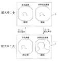
例えば指示操作部59により第1の制御状態にCPU58がある場合、ズームスイッチ27の調整状態がデフォルトの拡大率が小の状態の場合をCPU58が検出している際には、図4に示すように、フリーズメモリ部54、55、56を介した画像合成回路57によりモニタ4には、通常光画像及び蛍光画像が動画として表示される。そして、ズームスイッチ27が操作され、調整状態が所定の拡大率となり、CPU58がその状態(例えば拡大率:大)を検出すると、通常光画像及び狭帯域光画像が動画としてモニタ4に表示される。 For example, when the
また、例えば指示操作部59により第2の制御状態にCPU58がある場合、ズームスイッチ27の調整状態がデフォルトの拡大率が小の状態の場合をCPU58が検出している際には、図5に示すように、フリーズメモリ部54、55、56を介した画像合成回路57によりモニタ4には、蛍光画像及び狭帯域光画像が動画として表示される。そして、ズームスイッチ27が操作され、調整状態が所定の拡大率となり、CPU58がその状態(例えば拡大率:大)を検出すると、フリーズメモリ部56に格納されている蛍光画像が静止画として、また狭帯域光画像が動画としてモニタ4に表示される。 Further, for example, when the
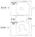
また、例えば指示操作部59により第3の制御状態にCPU58がある場合、ズームスイッチ27の調整状態がデフォルトの拡大率が小の状態の場合をCPU58が検出している際には、図6に示すように、フリーズメモリ部54、55、56を介した画像合成回路57によりモニタ4には、蛍光画像及び狭帯域光画像が動画として表示される。そして、ズームスイッチ27が操作され、調整状態が所定の拡大率となり、CPU58がその状態(例えば拡大率:大)を検出すると、狭帯域光画像のみが動画としてモニタ4に表示される。 In addition, for example, when the
さらに、例えば指示操作部59により第4の制御状態にCPU58がある場合、ズームスイッチ27の調整状態がデフォルトの拡大率が小の状態の場合をCPU58が検出している際には、図7に示すように、フリーズメモリ部54、55、56を介した画像合成回路57によりモニタ4には、通常光画像が動画として表示される。そして、ズームスイッチ27が操作され、調整状態が所定の拡大率となり、CPU58がその状態(例えば拡大率:大)を検出すると、狭帯域光画像が動画としてモニタ4に表示される。 Further, for example, when the
このように本実施例では、ズームスイッチ27による観察状態に応じて、CPU58の制御により複数の観察モードを適切に切り替えることができる。 As described above, in this embodiment, the plurality of observation modes can be appropriately switched by the control of the
なお、指示操作部59による制御状態によりCPU58がフリーズメモリ部54、55、56及び画像合成回路57を制御し、モニタに表示する表示形態は上記形態(図4、図5、図6及び図7)に限らないことはいうまでもない。 Note that the
また、本実施例では、ビームスプリッタ23により光路を分離し、通常観察光/狭帯域光用CCD24及び蛍光用CCD26により撮像するとしたが、これに限らず、図8に示すように、通常観察光/狭帯域光用CCD24及び蛍光用CCD26の対物光学系を2系統設けるようにしてもよい。 In this embodiment, the optical path is separated by the
図9及び図10は本発明の実施例2に係わり、図9は内視鏡装置の構成を示す構成図、図10は図9の内視鏡装置の作用を説明する図である。 9 and 10 relate to the second embodiment of the present invention, FIG. 9 is a configuration diagram showing the configuration of the endoscope apparatus, and FIG. 10 is a diagram for explaining the operation of the endoscope apparatus of FIG.
実施例2は、実施例1とほとんど同じであるので、異なる点のみ説明し、同一の構成には同じ符号をつけ説明は省略する。 Since the second embodiment is almost the same as the first embodiment, only different points will be described, and the same components are denoted by the same reference numerals and description thereof will be omitted.
本実施例では、図9に示すように、電子内視鏡3に接触用対物レンズ81及び接触観察用CCD82に接触観察用光学系を設けている。該接触観察用光学系は、例えば特開2004−166913号公報(同公報図4)等に開示され、公知であるので説明は省略する。 In this embodiment, as shown in FIG. 9, the
また、ビデオプロセッサ5には、接触観察用CCD82からの撮像信号を信号処理し接触観察画像を生成しフリーズメモリ部84を介して画像合成回路57に出力する接触観察用ビデオ回路83を備えている。 Further, the
なお、フリーズメモリ部84は、フリーズメモリ部54、55、56と同じ構成である(図3参照)。その他の構成は実施例1と同じである。 The
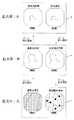
本実施例では、例えば指示操作部59により所定の制御状態にCPU58がある場合、ズームスイッチ27の調整状態がデフォルトの拡大率が小の状態の場合をCPU58が検出している際には、図10に示すように、フリーズメモリ部54、55、56を介した画像合成回路57によりモニタ4には、通常光画像及び蛍光画像が動画として表示される。そして、ズームスイッチ27が操作され、調整状態が所定の第1の拡大率となり、CPU58がその状態(例えば拡大率:中)を検出すると、通常光画像及び狭帯域光画像が動画としてモニタ4に表示される。さらに、ズームスイッチ27が操作され、調整状態が所定の第2の拡大率となり、CPU58がその状態(例えば拡大率:大)を検出すると、通常光画像及び接触観察画像が動画としてモニタ4に表示される。 In this embodiment, for example, when the
なお、上記各実施例において、ズームは手動のものに限らず、電子内視鏡先端にアクチュエータを備えた電動ズームでもよい。 In each of the above-described embodiments, the zoom is not limited to a manual one, and may be an electric zoom including an actuator at the tip of the electronic endoscope.
また、観察モードは、上記のモード(例えば、通常光観察、狭帯域光観察、蛍光観察等)に限らず、赤外光観察モード、紫外光観察モードであってもよい。 Further, the observation mode is not limited to the above mode (for example, normal light observation, narrow band light observation, fluorescence observation, etc.), but may be an infrared light observation mode or an ultraviolet light observation mode.
本発明は、上述した実施例に限定されるものではなく、本発明の要旨を変えない範囲において、種々の変更、改変等が可能である。 The present invention is not limited to the above-described embodiments, and various changes and modifications can be made without departing from the scope of the present invention.
1…内視鏡装置
2…電子内視鏡
3…光源装置
4…モニタ
5…ビデオプロセッサ
20…挿入部
21…ライトガイドファイバ
22…ズームレンズ
23…ビームスプリッタ
24…通常観察光/狭帯域光用CCD
25…励起光カットフィルタ
26…蛍光用CCD
27…ズームスイッチ
31…ランプ
32…回転フィルタ
51…通常画像用ビデオ回路
52…狭帯域画像用ビデオ回路
53…蛍光画像用ビデオ回路
54、55、56…フリーズメモリ部
57…画像合成回路
58…CPU
59…指示操作部DESCRIPTION OF SYMBOLS 1 ...
25 ... Excitation light cut
27 ... zoom
59. Instruction operation unit
Claims (3)
Translated fromJapanese前記観察モードの観察状態を設定する観察状態設定手段と、
前記観察状態を検知し、検知した観察状態に基づいて前記複数の観察モード画像処理手段を制御する処理制御手段と
を備えたことを特徴とする画像処理装置。A plurality of observation mode image processing means for generating observation images of a subject in a plurality of observation modes;
An observation state setting means for setting an observation state in the observation mode;
An image processing apparatus comprising: a processing control unit that detects the observation state and controls the plurality of observation mode image processing units based on the detected observation state.
ことを特徴とする請求項1に記載の画像処理装置。The image processing apparatus according to claim 1, wherein the observation state is a magnification of the observation mode.
ことを特徴とする請求項1または2に記載の画像処理装置。The plurality of observation modes include a normal observation mode with observation light in a normal visible light band, a narrow band observation mode with narrow observation light within the normal visible light band, and a fluorescence observation mode with fluorescence observation light. The image processing apparatus according to claim 1 or 2.
Priority Applications (1)
| Application Number | Priority Date | Filing Date | Title |
|---|---|---|---|
| JP2005204754AJP4794928B2 (en) | 2005-07-13 | 2005-07-13 | Image processing device |
Applications Claiming Priority (1)
| Application Number | Priority Date | Filing Date | Title |
|---|---|---|---|
| JP2005204754AJP4794928B2 (en) | 2005-07-13 | 2005-07-13 | Image processing device |
Publications (2)
| Publication Number | Publication Date |
|---|---|
| JP2007020728Atrue JP2007020728A (en) | 2007-02-01 |
| JP4794928B2 JP4794928B2 (en) | 2011-10-19 |
Family
ID=37782281
Family Applications (1)
| Application Number | Title | Priority Date | Filing Date |
|---|---|---|---|
| JP2005204754AExpired - Fee RelatedJP4794928B2 (en) | 2005-07-13 | 2005-07-13 | Image processing device |
Country Status (1)
| Country | Link |
|---|---|
| JP (1) | JP4794928B2 (en) |
Cited By (16)
| Publication number | Priority date | Publication date | Assignee | Title |
|---|---|---|---|---|
| EP2179687A2 (en) | 2008-10-22 | 2010-04-28 | FUJIFILM Corporation | Endoscope apparatus and control method therefor |
| EP2189099A1 (en) | 2008-11-21 | 2010-05-26 | Fujifilm Corporation | Endoscope apparatus and its control method |
| JP2010136748A (en)* | 2008-12-09 | 2010-06-24 | Fujifilm Corp | Endoscope apparatus and control method thereof |
| JP2010142547A (en)* | 2008-12-22 | 2010-07-01 | Fujifilm Corp | Endoscopic image processing apparatus and method, and program. |
| WO2010116902A1 (en) | 2009-04-09 | 2010-10-14 | オリンパスメディカルシステムズ株式会社 | Endoscopic device |
| EP2258252A1 (en) | 2009-06-04 | 2010-12-08 | FUJIFILM Corporation | Endoscopic image processing apparatus, method and program |
| EP2371267A1 (en) | 2010-03-29 | 2011-10-05 | Fujifilm Corporation | Endoscope apparatus |
| JP2011254937A (en)* | 2010-06-08 | 2011-12-22 | Fujifilm Corp | Image processing system, method and program |
| JP2012130629A (en)* | 2010-12-24 | 2012-07-12 | Fujifilm Corp | Endoscopic diagnosis system |
| WO2012157338A1 (en)* | 2011-05-17 | 2012-11-22 | オリンパスメディカルシステムズ株式会社 | Medical instrument, method for controlling marker display in medical images, and medical processor |
| JP2015027470A (en)* | 2014-08-25 | 2015-02-12 | 富士フイルム株式会社 | Endoscope device |
| JP2016022325A (en)* | 2014-07-24 | 2016-02-08 | オリンパス株式会社 | Observation apparatus |
| WO2016056332A1 (en)* | 2014-10-06 | 2016-04-14 | オリンパス株式会社 | Image acquisition system |
| JPWO2019093356A1 (en)* | 2017-11-13 | 2020-11-19 | 富士フイルム株式会社 | Endoscopic system and how to operate it |
| JPWO2021060159A1 (en)* | 2019-09-27 | 2021-04-01 | ||
| WO2021131468A1 (en)* | 2019-12-26 | 2021-07-01 | 富士フイルム株式会社 | Endoscope system and method for operating same |
Citations (4)
| Publication number | Priority date | Publication date | Assignee | Title |
|---|---|---|---|---|
| JP2002233492A (en)* | 2000-12-04 | 2002-08-20 | Fuji Photo Film Co Ltd | Fluorescent image pickup device |
| JP2003126017A (en)* | 2001-10-25 | 2003-05-07 | Olympus Optical Co Ltd | Surgical microscope system |
| JP2003334160A (en)* | 2002-05-21 | 2003-11-25 | Olympus Optical Co Ltd | Stereoscopic endoscope system |
| JP2004024656A (en)* | 2002-06-27 | 2004-01-29 | Fuji Photo Film Co Ltd | Fluorescent endoscope equipment |
- 2005
- 2005-07-13JPJP2005204754Apatent/JP4794928B2/ennot_activeExpired - Fee Related
Patent Citations (4)
| Publication number | Priority date | Publication date | Assignee | Title |
|---|---|---|---|---|
| JP2002233492A (en)* | 2000-12-04 | 2002-08-20 | Fuji Photo Film Co Ltd | Fluorescent image pickup device |
| JP2003126017A (en)* | 2001-10-25 | 2003-05-07 | Olympus Optical Co Ltd | Surgical microscope system |
| JP2003334160A (en)* | 2002-05-21 | 2003-11-25 | Olympus Optical Co Ltd | Stereoscopic endoscope system |
| JP2004024656A (en)* | 2002-06-27 | 2004-01-29 | Fuji Photo Film Co Ltd | Fluorescent endoscope equipment |
Cited By (37)
| Publication number | Priority date | Publication date | Assignee | Title |
|---|---|---|---|---|
| US8553075B2 (en) | 2008-10-22 | 2013-10-08 | Fujifilm Corporation | Endoscope apparatus and control method therefor |
| EP2179687A2 (en) | 2008-10-22 | 2010-04-28 | FUJIFILM Corporation | Endoscope apparatus and control method therefor |
| EP2335551A1 (en) | 2008-10-22 | 2011-06-22 | Fujifilm Corporation | Endoscope apparatus and control method therefor |
| EP2189099A1 (en) | 2008-11-21 | 2010-05-26 | Fujifilm Corporation | Endoscope apparatus and its control method |
| US8439823B2 (en) | 2008-11-21 | 2013-05-14 | Fujifilm Corporation | Endoscope apparatus and its control method |
| JP2010136748A (en)* | 2008-12-09 | 2010-06-24 | Fujifilm Corp | Endoscope apparatus and control method thereof |
| JP2010142547A (en)* | 2008-12-22 | 2010-07-01 | Fujifilm Corp | Endoscopic image processing apparatus and method, and program. |
| JPWO2010116902A1 (en)* | 2009-04-09 | 2012-10-18 | オリンパスメディカルシステムズ株式会社 | Endoscope device |
| CN102387736A (en)* | 2009-04-09 | 2012-03-21 | 奥林巴斯医疗株式会社 | Endoscopic device |
| EP2417897A4 (en)* | 2009-04-09 | 2012-11-07 | Olympus Medical Systems Corp | ENDOSCOPIC DEVICE |
| JP2012245362A (en)* | 2009-04-09 | 2012-12-13 | Olympus Medical Systems Corp | Endoscope device and focus position adjustment method for the same |
| WO2010116902A1 (en) | 2009-04-09 | 2010-10-14 | オリンパスメディカルシステムズ株式会社 | Endoscopic device |
| EP2258252A1 (en) | 2009-06-04 | 2010-12-08 | FUJIFILM Corporation | Endoscopic image processing apparatus, method and program |
| JP2011206226A (en)* | 2010-03-29 | 2011-10-20 | Fujifilm Corp | Endoscopic system |
| EP2371267A1 (en) | 2010-03-29 | 2011-10-05 | Fujifilm Corporation | Endoscope apparatus |
| US9232883B2 (en) | 2010-03-29 | 2016-01-12 | Fujifilm Corporation | Endoscope apparatus |
| JP2011254937A (en)* | 2010-06-08 | 2011-12-22 | Fujifilm Corp | Image processing system, method and program |
| JP2012130629A (en)* | 2010-12-24 | 2012-07-12 | Fujifilm Corp | Endoscopic diagnosis system |
| US9456738B2 (en) | 2010-12-24 | 2016-10-04 | Fujifilm Corporation | Endoscopic diagnosis system |
| CN103298393A (en)* | 2011-05-17 | 2013-09-11 | 奥林巴斯医疗株式会社 | Medical instrument, method for controlling marker display in medical images, and medical processor |
| US8876700B2 (en) | 2011-05-17 | 2014-11-04 | Olympus Medical Systems Corp. | Medical apparatus, method for controlling marker display in medical image and medical processor |
| JP5274724B2 (en)* | 2011-05-17 | 2013-08-28 | オリンパスメディカルシステムズ株式会社 | Medical device, method of operating medical processor and medical processor |
| WO2012157338A1 (en)* | 2011-05-17 | 2012-11-22 | オリンパスメディカルシステムズ株式会社 | Medical instrument, method for controlling marker display in medical images, and medical processor |
| JP2016022325A (en)* | 2014-07-24 | 2016-02-08 | オリンパス株式会社 | Observation apparatus |
| JP2015027470A (en)* | 2014-08-25 | 2015-02-12 | 富士フイルム株式会社 | Endoscope device |
| WO2016056332A1 (en)* | 2014-10-06 | 2016-04-14 | オリンパス株式会社 | Image acquisition system |
| JP6049949B2 (en)* | 2014-10-06 | 2016-12-21 | オリンパス株式会社 | Imaging system |
| US10191271B2 (en) | 2014-10-06 | 2019-01-29 | Olympus Corporation | Image pickup system |
| JPWO2019093356A1 (en)* | 2017-11-13 | 2020-11-19 | 富士フイルム株式会社 | Endoscopic system and how to operate it |
| US11089943B2 (en) | 2017-11-13 | 2021-08-17 | Fujifilm Corporation | Endoscope system and method of operating the same |
| JPWO2021060159A1 (en)* | 2019-09-27 | 2021-04-01 | ||
| WO2021060159A1 (en)* | 2019-09-27 | 2021-04-01 | 富士フイルム株式会社 | Image processing device, endoscopic system, and operation method of image processing |
| CN114521122A (en)* | 2019-09-27 | 2022-05-20 | 富士胶片株式会社 | Image processing apparatus, endoscope system, and image processing method |
| JP7196330B2 (en) | 2019-09-27 | 2022-12-26 | 富士フイルム株式会社 | Image processing device, endoscope system, and method of operating image processing device |
| WO2021131468A1 (en)* | 2019-12-26 | 2021-07-01 | 富士フイルム株式会社 | Endoscope system and method for operating same |
| JPWO2021131468A1 (en)* | 2019-12-26 | 2021-07-01 | ||
| JP7362778B2 (en) | 2019-12-26 | 2023-10-17 | 富士フイルム株式会社 | Endoscope system and its operating method |
Also Published As
| Publication number | Publication date |
|---|---|
| JP4794928B2 (en) | 2011-10-19 |
Similar Documents
| Publication | Publication Date | Title |
|---|---|---|
| JP5127639B2 (en) | Endoscope system and method of operating the same | |
| JP5203861B2 (en) | Endoscope system and method of operating the same | |
| JP4891990B2 (en) | Endoscope device | |
| JP4794928B2 (en) | Image processing device | |
| JP5308815B2 (en) | Biological observation system | |
| JP6005303B2 (en) | Fluorescence observation endoscope system | |
| JP4643481B2 (en) | Image processing device | |
| EP1743568B1 (en) | Image processing device | |
| WO2003075752A1 (en) | Endoscope image processing apparatus | |
| JP4855728B2 (en) | Illumination device and observation device | |
| JP2015029841A (en) | Imaging apparatus and imaging method | |
| JP2006198106A (en) | Electronic endoscope system | |
| JP4709606B2 (en) | Biological observation device | |
| WO2020178962A1 (en) | Endoscope system and image processing device | |
| JP4989036B2 (en) | Signal processing apparatus for electronic endoscope and electronic endoscope apparatus | |
| JP5334952B2 (en) | Image processing device | |
| JP5148054B2 (en) | Imaging system | |
| JP4744279B2 (en) | Electronic endoscope device | |
| JP5764472B2 (en) | Endoscopic diagnosis device | |
| JP2006340855A (en) | Image processing device | |
| JP7123247B2 (en) | Endoscope control device, method and program for changing wavelength characteristics of illumination light by endoscope control device | |
| JP6586206B2 (en) | Endoscope system and operating method thereof | |
| JP2005034491A (en) | Probe-type observing equipment and endoscope apparatus | |
| JP2007160123A (en) | Endoscope and endoscope system | |
| JP2013102898A (en) | Endoscopic diagnostic apparatus |
Legal Events
| Date | Code | Title | Description |
|---|---|---|---|
| A621 | Written request for application examination | Free format text:JAPANESE INTERMEDIATE CODE: A621 Effective date:20080530 | |
| A977 | Report on retrieval | Free format text:JAPANESE INTERMEDIATE CODE: A971007 Effective date:20110121 | |
| A131 | Notification of reasons for refusal | Free format text:JAPANESE INTERMEDIATE CODE: A131 Effective date:20110201 | |
| A521 | Request for written amendment filed | Free format text:JAPANESE INTERMEDIATE CODE: A523 Effective date:20110404 | |
| A131 | Notification of reasons for refusal | Free format text:JAPANESE INTERMEDIATE CODE: A131 Effective date:20110426 | |
| A521 | Request for written amendment filed | Free format text:JAPANESE INTERMEDIATE CODE: A523 Effective date:20110623 | |
| TRDD | Decision of grant or rejection written | ||
| A01 | Written decision to grant a patent or to grant a registration (utility model) | Free format text:JAPANESE INTERMEDIATE CODE: A01 Effective date:20110719 | |
| A01 | Written decision to grant a patent or to grant a registration (utility model) | Free format text:JAPANESE INTERMEDIATE CODE: A01 | |
| A61 | First payment of annual fees (during grant procedure) | Free format text:JAPANESE INTERMEDIATE CODE: A61 Effective date:20110727 | |
| R151 | Written notification of patent or utility model registration | Ref document number:4794928 Country of ref document:JP Free format text:JAPANESE INTERMEDIATE CODE: R151 | |
| FPAY | Renewal fee payment (event date is renewal date of database) | Free format text:PAYMENT UNTIL: 20140805 Year of fee payment:3 | |
| S111 | Request for change of ownership or part of ownership | Free format text:JAPANESE INTERMEDIATE CODE: R313111 | |
| R350 | Written notification of registration of transfer | Free format text:JAPANESE INTERMEDIATE CODE: R350 | |
| S531 | Written request for registration of change of domicile | Free format text:JAPANESE INTERMEDIATE CODE: R313531 | |
| R350 | Written notification of registration of transfer | Free format text:JAPANESE INTERMEDIATE CODE: R350 | |
| R250 | Receipt of annual fees | Free format text:JAPANESE INTERMEDIATE CODE: R250 | |
| R250 | Receipt of annual fees | Free format text:JAPANESE INTERMEDIATE CODE: R250 | |
| R250 | Receipt of annual fees | Free format text:JAPANESE INTERMEDIATE CODE: R250 | |
| LAPS | Cancellation because of no payment of annual fees |