JP2007020047A - Communication control method and communication system - Google Patents
Communication control method and communication systemDownload PDFInfo
- Publication number
- JP2007020047A JP2007020047AJP2005201401AJP2005201401AJP2007020047AJP 2007020047 AJP2007020047 AJP 2007020047AJP 2005201401 AJP2005201401 AJP 2005201401AJP 2005201401 AJP2005201401 AJP 2005201401AJP 2007020047 AJP2007020047 AJP 2007020047A
- Authority
- JP
- Japan
- Prior art keywords
- transmission
- reception
- systems
- normal
- receiving
- Prior art date
- Legal status (The legal status is an assumption and is not a legal conclusion. Google has not performed a legal analysis and makes no representation as to the accuracy of the status listed.)
- Withdrawn
Links
- 238000004891communicationMethods0.000titleclaimsabstractdescription69
- 238000000034methodMethods0.000titleclaimsabstractdescription26
- 230000002159abnormal effectEffects0.000claimsabstractdescription57
- 230000005540biological transmissionEffects0.000claimsdescription227
- 238000012544monitoring processMethods0.000claimsdescription54
- 238000000926separation methodMethods0.000claimsdescription20
- 230000005856abnormalityEffects0.000claimsdescription5
- 230000006866deteriorationEffects0.000abstractdescription3
- 238000010586diagramMethods0.000description4
- 238000011084recoveryMethods0.000description3
- 238000001514detection methodMethods0.000description2
- 239000000284extractSubstances0.000description2
- 230000015556catabolic processEffects0.000description1
- 238000006243chemical reactionMethods0.000description1
- 238000006731degradation reactionMethods0.000description1
- 230000000694effectsEffects0.000description1
Images


Classifications
- H—ELECTRICITY
- H04—ELECTRIC COMMUNICATION TECHNIQUE
- H04B—TRANSMISSION
- H04B7/00—Radio transmission systems, i.e. using radiation field
- H04B7/02—Diversity systems; Multi-antenna system, i.e. transmission or reception using multiple antennas
- H04B7/04—Diversity systems; Multi-antenna system, i.e. transmission or reception using multiple antennas using two or more spaced independent antennas
- H04B7/06—Diversity systems; Multi-antenna system, i.e. transmission or reception using multiple antennas using two or more spaced independent antennas at the transmitting station
- H04B7/0686—Hybrid systems, i.e. switching and simultaneous transmission
- H04B7/0691—Hybrid systems, i.e. switching and simultaneous transmission using subgroups of transmit antennas
- H—ELECTRICITY
- H04—ELECTRIC COMMUNICATION TECHNIQUE
- H04B—TRANSMISSION
- H04B7/00—Radio transmission systems, i.e. using radiation field
- H04B7/02—Diversity systems; Multi-antenna system, i.e. transmission or reception using multiple antennas
- H04B7/04—Diversity systems; Multi-antenna system, i.e. transmission or reception using multiple antennas using two or more spaced independent antennas
- H04B7/06—Diversity systems; Multi-antenna system, i.e. transmission or reception using multiple antennas using two or more spaced independent antennas at the transmitting station
- H04B7/0602—Diversity systems; Multi-antenna system, i.e. transmission or reception using multiple antennas using two or more spaced independent antennas at the transmitting station using antenna switching
- H04B7/0608—Antenna selection according to transmission parameters
- H04B7/061—Antenna selection according to transmission parameters using feedback from receiving side
- H—ELECTRICITY
- H04—ELECTRIC COMMUNICATION TECHNIQUE
- H04B—TRANSMISSION
- H04B7/00—Radio transmission systems, i.e. using radiation field
- H04B7/02—Diversity systems; Multi-antenna system, i.e. transmission or reception using multiple antennas
- H04B7/04—Diversity systems; Multi-antenna system, i.e. transmission or reception using multiple antennas using two or more spaced independent antennas
- H04B7/08—Diversity systems; Multi-antenna system, i.e. transmission or reception using multiple antennas using two or more spaced independent antennas at the receiving station
- H04B7/0868—Hybrid systems, i.e. switching and combining
- H04B7/0874—Hybrid systems, i.e. switching and combining using subgroups of receive antennas
Landscapes
- Engineering & Computer Science (AREA)
- Computer Networks & Wireless Communication (AREA)
- Signal Processing (AREA)
- Radio Transmission System (AREA)
- Mobile Radio Communication Systems (AREA)
Abstract
Description
Translated fromJapanese本発明は、MIMO(Multiple Input Multiple Output)通信に代表される、送信側および受信側のそれぞれに複数のアンテナを用いて行う無線通信における通信制御方法および通信システムに関する。 The present invention relates to a communication control method and a communication system in wireless communication performed by using a plurality of antennas on each of a transmission side and a reception side, represented by MIMO (Multiple Input Multiple Output) communication.
MIMO装置では、送信側は、通信対象の情報を複数に分割して同一の周波数を使って、同時に複数の送信アンテナから送出する。受信側は、送信側から送出された情報を複数の受信アンテナで受信し、各受信アンテナが受信する情報について他の受信アンテナが受信する情報と重複する部分を分離し、元の情報に組み立て直す。MIMO通信は、理論上では送信アンテナおよび受信アンテナの数に比例して通信速度を向上させることができると一般的に言われている。そのため、多重化のために広帯域を確保する必要がなく、周波数の利用効率に優れているという利点がある(例えば、特許文献1参照)。
しかし、MIMO装置の運用中に受信側装置が故障して「送信アンテナ数>受信アンテナ数」の関係になると、受信側装置の受信特性が劣化してしまうという問題がある。 However, there is a problem that the reception characteristic of the reception side apparatus deteriorates when the reception side apparatus breaks down during the operation of the MIMO apparatus and the relation of “number of transmission antennas> number of reception antennas” is satisfied.
本発明は上述したような従来の技術が有する問題点を解決するためになされたものであり、送信側および受信側のそれぞれに複数のアンテナを備えた通信システムにおいて、受信側装置の故障による、通信特性の劣化を抑制した通信制御方法および通信システムを提供することを目的とする。 The present invention has been made in order to solve the problems of the prior art as described above, and in a communication system having a plurality of antennas on each of the transmission side and the reception side, due to failure of the reception side device, It is an object of the present invention to provide a communication control method and a communication system in which deterioration of communication characteristics is suppressed.
上記目的を達成するための本発明の通信制御方法は、アンテナおよび送信機を含む送信系統が複数設けられた送信側装置とアンテナおよび受信機を含む受信系統が複数設けられた受信側装置との通信における制御方法であって、
前記受信側装置が、前記複数の受信系統のいずれかについて正常から異常への状態変化または異常から正常への状態変化を検出すると、正常な受信系統の数と同等以下の数を前記送信側装置の前記送信系統の数として算出するステップと、
前記受信側装置が、算出した前記送信系統の数の情報である送信系統数情報を前記送信側装置に送信するステップと、
前記送信側装置が、前記受信側装置から前記送信系統数情報を受信すると、動作させる送信系統の数を該送信系統数情報が示す数に一致させるステップと、
を有するものである。In order to achieve the above object, a communication control method of the present invention includes a transmission side device provided with a plurality of transmission systems including an antenna and a transmitter and a reception side device provided with a plurality of reception systems including an antenna and a receiver. A control method in communication,
When the receiving side apparatus detects a state change from normal to abnormal or a state change from abnormal to normal for any one of the plurality of receiving systems, the transmitting side apparatus sets a number equal to or less than the number of normal receiving systems. Calculating as the number of transmission systems of
The reception side device transmits transmission system number information that is information of the calculated number of transmission systems to the transmission side device;
When the transmission side apparatus receives the transmission system number information from the reception side apparatus, the number of transmission systems to be operated is matched with the number indicated by the transmission system number information;
It is what has.
また、本発明の通信制御方法は、アンテナおよび送信機を含む送信系統が複数設けられた送信側装置とアンテナおよび受信機を含む受信系統が複数設けられた受信側装置との通信における通信制御方法であって、
前記受信側装置が、前記複数の受信系統のいずれかについて正常から異常への状態変化または異常から正常への状態変化を検出すると、正常な受信系統の数を示す情報である正常受信系統数情報を前記送信側装置に送信するステップと、
前記送信側装置が、前記受信側装置から前記正常受信系統数情報を受信すると、動作させる送信系統の数を、該正常受信系統数情報が示す数と同等以下にするステップと、
を有するものである。Further, the communication control method of the present invention is a communication control method in communication between a transmission side device provided with a plurality of transmission systems including an antenna and a transmitter and a reception side device provided with a plurality of reception systems including an antenna and a receiver. Because
When the receiving side apparatus detects a state change from normal to abnormal or a state change from abnormal to normal for any one of the plurality of reception systems, the number of normal reception systems is information indicating the number of normal reception systems Transmitting to the transmitting device;
When the transmission side apparatus receives the normal reception system number information from the reception side apparatus, the number of transmission systems to be operated is made equal to or less than the number indicated by the normal reception system number information;
It is what has.
一方、上記目的を達成するための本発明の通信システムは、アンテナおよび送信機を含む送信系統が複数設けられた送信側装置とアンテナおよび受信機を含む受信系統が複数設けられた受信側装置とを有する通信システムであって、
前記受信側装置は、
前記複数の受信系統と接続され、該複数の受信系統の状態を監視し、該複数の受信系統のいずれかについて正常から異常への状態変化または異常から正常への状態変化を検出すると、正常な受信系統の数と同等以下の数を前記送信系統の数として算出し、算出した数を前記送信系統数情報として外部に送出する監視部、および該監視部と接続され、該監視部から受信する該送信系統数情報を前記送信側装置に無線通信で送信する受信側送信系統を有し、
前記送信側装置は、
前記複数の送信系統と接続され、前記送信系統数情報に対応する数の該送信系統に送信データを振り分ける信号分配処理部、および該信号分配処理部と接続され、前記受信側装置から無線通信で受信する該送信系統数情報を該信号分配処理部に送出する送信側受信系統を有する、構成である。On the other hand, a communication system of the present invention for achieving the above object includes a transmission side device provided with a plurality of transmission systems including an antenna and a transmitter, and a reception side device provided with a plurality of reception systems including an antenna and a receiver. A communication system comprising:
The receiving side device
Connected to the plurality of receiving systems, monitoring the state of the plurality of receiving systems, and detecting a state change from normal to abnormal or a state change from abnormal to normal for any of the plurality of receiving systems, A number equal to or less than the number of reception systems is calculated as the number of transmission systems, and the calculated number is transmitted to the outside as the transmission system number information, and is connected to the monitoring unit and receives from the monitoring unit Having a receiving side transmission system for transmitting the transmission system number information to the transmitting side device by wireless communication;
The transmitting device is:
A signal distribution processing unit that is connected to the plurality of transmission systems and distributes transmission data to the number of transmission systems corresponding to the transmission system number information, and is connected to the signal distribution processing unit, and is wirelessly communicated from the receiving side device. This is a configuration having a transmission side reception system for transmitting the transmission system number information to be received to the signal distribution processing unit.
また、本発明の通信システムは、アンテナおよび送信機を含む送信系統が複数設けられた送信側装置とアンテナおよび受信機を含む受信系統が複数設けられた受信側装置とを有する通信システムであって、
前記受信側装置は、
前記複数の受信系統と接続され、該複数の受信系統の状態を監視し、該複数の受信系統のいずれかについて正常から異常への状態変化または異常から正常への状態変化を検出すると、正常な受信系統の数を示す情報である正常受信系統数情報を外部に送出する監視部、および該監視部と接続され、該監視部から受信する該正常受信系統数情報を前記送信側装置に無線通信で送信する送信系統を有し、
前記送信側装置は、
前記複数の送信系統と接続され、動作させる送信系統の数を示す送信系統数情報に対応する数の該送信系統に送信データを振り分ける信号分配処理部、該信号分配処理部と接続され、前記正常受信系統数情報を受信すると、該正常受信系統数情報が示す数と同等以下の数を前記送信系統数情報として算出し、該送信系統数情報を前記信号分配処理部に送出する監視部、および該監視部と接続され、前記受信側装置から無線通信で受信する該正常受信系統数情報を該監視部に送出する送信側受信系統を有する、構成である。The communication system of the present invention is a communication system having a transmission side device provided with a plurality of transmission systems including an antenna and a transmitter and a reception side device provided with a plurality of reception systems including an antenna and a receiver. ,
The receiving side device
Connected to the plurality of receiving systems, monitoring the state of the plurality of receiving systems, and detecting a state change from normal to abnormal or a state change from abnormal to normal for any of the plurality of receiving systems, A monitoring unit that sends out information on the number of normal reception systems, which is information indicating the number of reception systems, to the outside, and wireless communication of the information on the number of normal reception systems connected to the monitoring unit and received from the monitoring unit to the transmitting side device Has a transmission system to transmit in
The transmitting device is:
A signal distribution processing unit that is connected to the plurality of transmission systems and distributes transmission data to a number of transmission systems corresponding to transmission system number information indicating the number of transmission systems to be operated. When receiving the reception system number information, a number equal to or less than the number indicated by the normal reception system number information is calculated as the transmission system number information, and the monitoring unit sends the transmission system number information to the signal distribution processing unit, and A configuration is provided that includes a transmission-side reception system that is connected to the monitoring unit and transmits the normal reception system number information received from the reception-side device through wireless communication to the monitoring unit.
本発明では、通信中に受信側装置の故障や回復により動作可能な受信系統の数が変化しても、正常な受信系統の数が検出され、正常な受信系統の数に対応する、送信系統の数に変更される。そのため、複数の受信系統のいずれかに異常が発生したり、異常状態から回復したりしても、動作する送信系統の数が無線通信にとって最適な数に変更される。 In the present invention, the number of normal reception systems is detected and the transmission system corresponding to the number of normal reception systems is detected even if the number of operable reception systems changes due to failure or recovery of the receiving side device during communication. The number is changed. For this reason, even if an abnormality occurs in any of the plurality of reception systems or a recovery from the abnormal state, the number of operating transmission systems is changed to an optimum number for wireless communication.
本発明によれば、受信側装置の受信系統にハードウェアの故障やDSPファームウェアの暴走等による故障が発生すると、送信側装置で「送信系統数≦受信系統数」の条件になるように送信系統の数を制御する。その結果、動作する送信系統の数が無線通信にとって最適な数に変更され、受信特性の劣化を抑制できる。また、受信系統がハードウェア交換などで故障状態から正常状態に変化した場合も同様である。 According to the present invention, when a hardware failure or a DSP firmware runaway occurs in the reception system of the reception side device, the transmission system is configured so that the condition of “the number of transmission systems ≦ the number of reception systems” is satisfied in the transmission side device. Control the number of As a result, the number of operating transmission systems is changed to an optimum number for wireless communication, and degradation of reception characteristics can be suppressed. The same applies when the receiving system changes from a failure state to a normal state due to hardware replacement or the like.
本発明の通信制御方法は、受信側での有効な受信アンテナ数を検出し、有効な受信アンテナ数に対応して、送信側における送信アンテナおよび送信機を含む送信系統の数の制御を行うものである。 The communication control method of the present invention detects the number of effective receiving antennas on the receiving side, and controls the number of transmission systems including transmitting antennas and transmitters on the transmitting side corresponding to the number of effective receiving antennas. It is.
本実施例のMIMO通信による通信システムの構成について説明する。 A configuration of a communication system using MIMO communication according to the present embodiment will be described.
図1は本実施例の通信システムの一構成例を示すブロック図である。図1に示すように、本実施例の通信システムは、MIMO送信側装置1とMIMO受信側装置13とを有する。 FIG. 1 is a block diagram illustrating a configuration example of a communication system according to the present embodiment. As shown in FIG. 1, the communication system of the present embodiment includes a MIMO
MIMO送信側装置1は、送信データ信号をMIMO受信側装置13に送信する送信系統26−1〜26−4と、送信系統の最適数を示す情報をMIMO受信側装置13から受信する受信系統30と、送信データ信号を送信系統26−1〜26−4に分配する信号分配処理部2とを有する。信号分配処理部2は、送信系統26−1〜26−4および受信系統30と通信接続されている。送信系統26−1〜26−4のそれぞれは、送信機3−1〜3−4のそれぞれと、アンテナ7−1〜7−4のそれぞれとを有する。受信系統30は受信機11およびアンテナ12を有する。なお、送信系統26−1〜26−4の構成はそれぞれ同様であるため、以下では、説明が重複する場合には代表して送信系統26−1で説明する。また、(送信系統数)×(受信系統数)をアンテナ形態として表記すると、本実施例では、図1に示すように、アンテナ形態を4×4の場合とする。 The MIMO
受信系統30の受信機11は、MIMO受信側装置13からアンテナ12を介して受信する無線データに対して復号化および変調等の処理を行って元のデータに変換する。そして、MIMO送信側装置1の送信系統の最適数を示す情報である送信系統数情報を含む無線データをMIMO受信側装置13から受信すると、無線データを復号化して送信系統数情報を読み出し、送信系統数情報を信号分配処理部2に送出する。 The receiver 11 of the reception system 30 performs processing such as decoding and modulation on the wireless data received from the MIMO receiving side device 13 via the antenna 12 and converts the wireless data into original data. Then, when wireless data including transmission system number information, which is information indicating the optimum number of transmission systems of the MIMO
信号分配処理部2は、受信系統30から送信系統数情報を受信すると、送信系統数情報が示す数の送信系統に送信データ信号を均等に割り振る。例えば、送信系統数情報が3の場合、信号分配処理部2は、送信系統26−1〜26−4のうちいずれか1つを除く3つの送信系統に送信データ信号を均等に割り振る。 When the signal
送信系統26−1の送信機3−1は、信号分配処理部2から送信データ信号を受け取ると、送信データ信号に対して符号化および変調等の処理を行って無線データに変換する。続いて、無線データをアンテナ7−1を介してMIMO受信側装置13に送信する。送信系統26−2〜26−4の動作についても送信系統26−1と同様である。 Upon receiving the transmission data signal from the signal
なお、送信データ信号を無線データに変換する処理および無線データを送信データに変換する処理を行うための無線通信方式については、従来と同様なためその詳細な説明を省略する。 Since the wireless communication scheme for performing the process of converting the transmission data signal into the wireless data and the process of converting the wireless data into the transmission data are the same as those in the prior art, detailed description thereof is omitted.
次に、MIMO受信側装置13について説明する。 Next, the MIMO receiving side device 13 will be described.
MIMO受信側装置13は、MIMO送信側装置1からの無線データを受信する受信系統31−1〜31−4と、受信系統31−1〜31−4から受け取るデータを元のデータに組み立てる信号分離処理部22と、受信系統31−1〜31−4の状態を監視する状態監視部23と、送信系統数情報を含む無線データをMIMO送信側装置1に送信する送信系統35とを有する。受信系統31−1〜31−4のそれぞれの出力信号線は信号分配処理部22に接続されている。状態監視部23は、受信系統31−1〜31−4、信号分配処理部22および送信系統35と通信接続されている。受信系統31−1〜31−4のそれぞれは、アンテナ14−1〜14−4のそれぞれと、受信機18−1〜18−4のそれぞれとを有する。送信系統35は送信機24およびアンテナ25を有する。なお、受信系統31−1〜31−4の構成は同様であるため、以下では、説明が重複する場合には代表して受信系統31−1で説明する。 The MIMO receiving side apparatus 13 receives the radio data from the MIMO transmitting
受信系統31−1の受信機18−1は、MIMO送信側装置1からアンテナ14−1を介して無線データを受信すると、無線データに対してパス検出および復号化等の処理を行って元のデータに変換した後、データを信号分離処理部22に送出する。受信系統31−2〜31−4の動作についても受信系統31−1と同様である。 When the receiver 18-1 of the reception system 31-1 receives wireless data from the MIMO
信号分離処理部22は、受信系統31−1〜31−4から受信するデータのうち重複部分を分離し、データを抽出して元のデータに組み立て直す。ただし、受信系統31−1〜31−4のうちいずれかに異常があり、異常のある受信系統を示す情報である異常受信系統情報を状態監視部23から受け取る場合、異常受信系統情報が示す受信系統から受信するデータについては処理対象から除外する。これにより異常のあるデータに対して処理をしなくて済むため、元のデータに組み立て直す処理にかかる負荷が軽減される。受信系統31−1〜31−4における異常とは、ハードウェアの故障やDSP(Digital Signal Processor)ファームウェアの暴走等により正常に動作しない状態をいう。一方、ハードウェアの故障の場合、ハードウェアを交換することで、受信系統は回復し、受信系統は異常状態から正常状態になる。 The signal
状態監視部23は、受信系統31−1〜31−4と通信接続され、受信系統31−1〜31−4が正常に動作しているか、それらの状態を監視する。監視により、受信系統31−1〜31−4のいずれかが正常状態から異常状態に変化したり、反対に異常状態から正常状態に回復したりすると、その状態変化を検出する。そして、正常に動作している受信系統の数からMIMO送信側装置1の送信系統の最適数を決定し、送信系統数情報を送信系統35に送出する。また、異常受信系統情報を信号処理分離部23に送出する。このようにして、状態監視部23では、常に現在動作している送信系統数を把握しており、受信系統31−1〜31−4の状態変化(正常→異常、異常→正常)により最適な送信系統数が変化するたびに送信系統数情報が更新される。 The
ここで、状態監視部23における、送信系統の最適数の求め方について説明する。 Here, how to obtain the optimum number of transmission systems in the
図2は送信系統の最適数を求めるための表である。MIMO送信側装置1に設けられた送信系統の総数をmとし、MIMO受信側装置13に設けられた受信系統の総数をnとしているため、アンテナ形態はm×nとなる。ただし、mおよびnは、1以上で、かつm≦nの条件を満たす整数である。図2は、受信系統の故障数に対して、送信系統の数をいくつにすれば最適であるかを示している。例えば、m=n=4の場合、図2に示す表から、受信系統の故障数が0のとき、正常な受信系統の数は4となり、送信系統の最適数は4となる。受信系統の故障数が3のときは、正常な受信系統の数は1となり、送信系統の最適数は1となる。送信系統の数を正常な受信系統の数と同等にすることで、送信側と受信側との通信のマッチングが最適となる。 FIG. 2 is a table for obtaining the optimum number of transmission systems. Since the total number of transmission systems provided in the MIMO
なお、図2の表では、送信系統の数を、最適数として正常な受信系統の数と同等にしたが、「正常な受信系統の数>送信系統の数」としてもよい。例えば、図2に示す表で、m=4、n=6の場合、受信系統の故障数が0〜2のとき、送信系統の数は4となる。受信系統の故障数が0または1であると、正常な受信系統の数は6または5になるため、「正常な受信系統の数>送信系統の数」の関係になる。 In the table of FIG. 2, the number of transmission systems is made equal to the number of normal reception systems as the optimum number, but “number of normal reception systems> number of transmission systems” may be used. For example, in the table shown in FIG. 2, when m = 4 and n = 6, the number of transmission systems is 4 when the number of failures in the reception system is 0-2. If the number of failures in the reception system is 0 or 1, the number of normal reception systems is 6 or 5, so that the relationship “number of normal reception systems> number of transmission systems” is established.
送信系統35の送信機24は、状態監視部23から送信系統数情報を受信すると、送信系統数情報を含むデータに対して無線通信方式にしたがって符号化および変調等の処理を行って無線データに変換し、無線データをアンテナ25を介してMIMO送信側装置1に送信する。 When the
次に、図1に示した通信システムの動作について説明する。 Next, the operation of the communication system shown in FIG. 1 will be described.
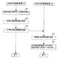
図3は本実施例の通信システムの動作手順を示すフローチャートである。 FIG. 3 is a flowchart showing the operation procedure of the communication system of the present embodiment.
MIMO送信側装置1の送信機3−1〜3−4のそれぞれは、信号分配処理部2から受信した送信データに対して符号化および変調等の処理を行って無線データを生成する。そして、アンテナ7−1〜7−4のそれぞれを介してMIMO受信側装置13に向けて無線データを送出する。MIMO受信側装置13の受信系統31−1〜31−4では、受信機18−1〜18−4のそれぞれがMIMO送信側装置1からアンテナ14−1〜14−4のそれぞれを介して無線データの信号を受信すると、パス検出および復号の処理を行って処理後のデータを信号分離処理部22へ送出する。信号分離処理部22は、受信系統31−1〜31−4からデータを受け取ると、受信系統毎にデータを分離してデータを抽出する。 Each of the transmitters 3-1 to 3-4 of the MIMO
状態監視部23は、受信系統31−1〜31−4の状態を監視し、いずれかの受信系統の状態変化(正常→異常、異常→正常)を検出すると(ステップ201)、送信系統の最適数を導出する(ステップ202)。続いて、送信系統の最適数を示す送信系統数情報を送信系統35に送出する。送信系統35は送信系統数情報をMIMO受信側装置1に送信する(ステップ203)。また、状態監視部23は、異常受信系統情報を信号分離処理部22に送出する。信号分離処理部22は、異常受信系統情報が示す受信系統からのデータを処理対象から除外する。 The
一方、MIMO送信側装置1の受信系統30は、MIMO受信側装置13から送信系統数情報を受信すると、送信系統数情報を信号分配処理部2に送出する。信号分配処理部2は、受信系統30から受信する送信系統数情報により送信データの振り分け先となる送信系統を決定し、決定した送信系統に対して、入力される送信データを均等に振り分ける(ステップ204)。例えば、送信系統数情報が3から1のそれぞれの場合については、次のようになる。 On the other hand, when receiving the transmission system number information from the MIMO reception side apparatus 13, the reception system 30 of the MIMO
送信系統数情報が3の場合、送信データを1/3ずつ送信系統26−1〜26−3に送信し、送信系統26−4には送信しない。送信系統数情報が2の場合、送信データを1/2ずつ送信系統26−1、26−2に送信し、送信系統26−3、26−4には送信しない。そして、送信系統数情報が1の場合、送信データをそのまま送信系統26−1に送信し、送信系統26−2〜26−4には送信しない。なお、異常となる受信系統がない場合、送信系統数情報は4となるため、信号分配処理部2は送信データを1/4ずつ送信系統26−1〜26−4に送信する。 When the transmission system number information is 3, transmission data is transmitted by 1/3 to the transmission systems 26-1 to 26-3 and not transmitted to the transmission system 26-4. When the transmission system number information is 2, the transmission data is transmitted by 1/2 to the transmission systems 26-1 and 26-2 and not transmitted to the transmission systems 26-3 and 26-4. When the transmission system number information is 1, the transmission data is transmitted as it is to the transmission system 26-1, and is not transmitted to the transmission systems 26-2 to 26-4. When there is no abnormal reception system, the transmission system number information is 4, and therefore the signal
ここで、ステップ201〜203で説明した状態監視部23の動作について具体例を説明する。状態監視部23には、受信系統31−1〜31−4から装置状態を示す信号である状態信号が入力されるものとする。例えば、装置が正常である場合には状態信号をLow信号とし、装置が故障などにより異常である場合には状態信号をHigh信号とする。そして、2値情報のうち、Low信号を「0」とし、High信号を「1」とする。この場合において、受信系統31−1が異常になったとき、状態監視部23は、受信系統31−1〜31−4のそれぞれからHigh信号、Low信号、Low信号、Low信号のそれぞれを受信する。状態監視部23は、このような信号を受信すると、信号が意味する情報を順に並べた「1000」を信号分離処理部22に送出する。また、状態監視部23は、受信系統31−1〜31−4から受け取った状態信号からLow信号の数をカウントし、その数を示す情報を送信系統数情報としてMIMO送信側装置1に送信する。この具体例で示したような、状態監視部23の信号出力は、論理回路を組み合わせた構成を状態監視部23に設けることで実現可能である。 Here, a specific example of the operation of the
図4はアンテナ形態4×4の場合において、信号分離処理部が処理対象とするデータの送信元の受信系統を示す表である。図4に示す受信系統の番号は、受信系統の符号31−1〜31−4の枝番号1〜4である。図4に示す表の左側欄には、行毎に受信系統の異なる状態が記述されている。そして、表の右側欄には、各行について、左側欄で「正常」とされた受信系統の枝番号が記述されている。左側欄と右側欄とを見比べると、異常のある受信系統は処理対象から除外されていることがわかる。 FIG. 4 is a table showing a reception system of a transmission source of data to be processed by the signal separation processing unit in the case of the
図4に示す表の左側欄に対して、上記状態監視部23の信号入出力についての具体例のように「正常」を情報「0」とし、「異常」を情報「1」として、受信系統の状態を示す情報を異常受信系統情報としてみる。第1行目は、受信系統が全て「正常」なので、情報を順に並べた「0000」が異常受信系統情報となる。この場合、異常となる受信系統がないため、表の右側欄に示すように、信号分離処理部22は、受信系統31−1〜31−4の全てから受信するデータを処理対象とする。第2行目は、受信系統31−4が異常なので、表の左側欄による情報「0001」が異常受信系統情報となる。信号分離処理部22は、状態監視部23から異常受信系統情報として情報「0001」を受信すると、表の右側欄に示すように、受信系統31−4を除いた受信系統31−1〜31−3から受信するデータを処理対象とする。図4に示す表の他の行についても、第1行目および第2行目と同様にして、左側欄に2値情報をあてはめることで、異常受信系統情報が論理回路で処理可能な情報となる。 For the left column of the table shown in FIG. 4, "normal" is information "0" and "abnormal" is information "1" as in the specific example of signal input / output of the
MIMO通信システムでは、運用中に受信系統にハードウェアの故障やDSPファームウェアの暴走等による故障が発生すると、動作可能な受信系統の数が変化し、「送信系統数>受信系統数」の関係になると受信特性が劣化する。本実施例の通信システムでは、受信側装置が故障すると、正常な受信系統の数が受信側装置で検出され、正常な受信系統の数に対応する、送信系統の数が送信側装置に通知される。これにより、送信側装置で「送信系統数≦受信系統数」の条件になるように送信系統の数が制御される。その結果、複数の受信系統のいずれかに異常が発生、または異常状態から回復しても、動作する送信系統の数が無線通信にとって最適な数に変更され、受信特性の劣化を抑制できる。 In a MIMO communication system, if a hardware failure or DSP firmware runaway occurs in the receiving system during operation, the number of operable receiving systems changes, and the relationship of “the number of transmitting systems> the number of receiving systems” is satisfied. As a result, reception characteristics deteriorate. In the communication system of this embodiment, when the receiving side device fails, the number of normal receiving systems is detected by the receiving side device, and the number of transmitting systems corresponding to the number of normal receiving systems is notified to the transmitting side device. The Thereby, the number of transmission systems is controlled so that the condition of “the number of transmission systems ≦ the number of reception systems” is satisfied at the transmission side apparatus. As a result, even if an abnormality occurs in any of the plurality of reception systems or recovers from the abnormal state, the number of operating transmission systems is changed to an optimum number for wireless communication, and deterioration of reception characteristics can be suppressed.
本実施例の通信システムは、受信側が受信系統の状態を送信側に通知し、送信側が送信系統の最適数を求めるようにしたものである。 In the communication system of this embodiment, the reception side notifies the transmission side of the state of the reception system, and the transmission side calculates the optimum number of transmission systems.
本実施例の通信システムの構成について説明する。 The configuration of the communication system according to the present embodiment will be described.
図5は本実施例の通信システムの一構成例を示す図である。なお、実施例1と同様な構成については同一の符号を付し、その詳細な説明を省略する。 FIG. 5 is a diagram illustrating a configuration example of a communication system according to the present embodiment. In addition, the same code | symbol is attached | subjected about the structure similar to Example 1, and the detailed description is abbreviate | omitted.
図5に示すように、MIMO受信側装置15には、受信系統31−1〜31−4の状態を監視する受信系統監視部36が設けられている。受信系統監視部36は、受信系統31−1〜31−4、信号分離処理部22、および送信系統35と通信接続されている。受信系統監視部36は、受信系統31−1〜31−4の状態を監視し、正常な受信系統の数を示す情報である受信系統数情報を送信系統35に送出する。また、異常な受信系統を示す情報である異常受信系統情報を信号分離処理部22に送出する。 As shown in FIG. 5, the MIMO reception side device 15 is provided with a reception
MIMO送信側装置10には、送信系統の最適数を信号分配処理部2に通知する送信系統制御部37が設けられている。送信系統制御部37は、信号分配処理部2および受信系統30と通信接続されている。送信系統制御部37は、受信系統30を介して受信系統数情報を受信すると、受信系統数情報から送信系統の最適数を算出し、送信系統の最適数の情報である送信系統数情報を信号分配処理部2に送出する。送信系統制御部37には、実施例1の状態監視部23と同様に、送信系統26−1〜26−4の数が記録された記憶回路が設けられている。 The MIMO transmission side apparatus 10 is provided with a transmission
なお、受信系統監視部36および送信系統制御部37の入出力信号を2値情報にすれば、実施例1の状態監視部23と同様に、受信系統監視部36および送信系統制御部37については、論理回路を組み合わせた構成とすることが可能である。 If the input / output signals of the reception
次に、図5に示した通信システムの動作について説明する。 Next, the operation of the communication system shown in FIG. 5 will be described.
図6は本実施例の通信システムの動作手順を示すフローチャートである。 FIG. 6 is a flowchart showing the operation procedure of the communication system of this embodiment.
図6に示すように、MIMO受信側装置15における受信系統監視部36は、受信系統の状態変化(正常→異常、異常→正常)を検出すると(ステップ301)、正常な受信系統の数を導出する(ステップ302)。正常な受信系統の数を示す正常受信系統数情報を送信系統35に送出し、異常受信系統情報を信号分離処理部22に送出する。送信系統35は、正常受信系統数情報をMIMO送信側装置10に送信する(ステップ303)。 As shown in FIG. 6, when the reception
MIMO送信側装置10の受信系統30は、MIMO受信側装置15から正常受信系統数情報を受信すると、正常受信系統数情報を送信系統制御部37に送出する。送信系統制御部37は、受信した正常受信系統数情報から送信系統の最適数を導出する(ステップ304)。続いて、送信系統の最適数を示す送信系統数情報を信号分配処理部2に送出する。信号分配処理部2は、送信系統数情報により送信系統を決定し、決定した送信系統に送信データを分配する制御を行う(ステップ305)。 When receiving the normal reception system number information from the MIMO reception side apparatus 15, the reception system 30 of the MIMO transmission side apparatus 10 sends the normal reception system number information to the transmission
本実施例の通信システムでは、運用中に受信側装置の故障や回復により動作可能な受信系統の数が変化しても、正常な受信系統の数が送信側装置に通知され、正常な受信系統の数に対応する、送信系統の数に変更される。そのため、実施例1と同様な効果が得られる。 In the communication system of the present embodiment, even if the number of operable reception systems changes due to failure or recovery of the reception side device during operation, the number of normal reception systems is notified to the transmission side device, and the normal reception system It is changed to the number of transmission systems corresponding to the number of. Therefore, the same effect as in Example 1 can be obtained.
なお、実施例1および実施例2では、4×4のアンテナ形態で示しているが、本発明に対応するアンテナ形態は「送信系統数≦受信系統数」の条件において任意である。 In the first and second embodiments, a 4 × 4 antenna form is shown, but the antenna form corresponding to the present invention is arbitrary under the condition “number of transmission systems ≦ number of reception systems”.
また、状態監視部23、受信系統監視部36および送信系統制御部37については、論理回路により動作させるものとしたが、プログラムを格納するためのメモリとCPU(Central Processing Unit)とを設け、CPUにプログラムを実行させることで動作させるようにしてもよい。 The
1、10 MIMO送信側装置
2 信号分配処理部
3−1〜3−4 送信機
7−1〜7−4、14−1〜14−4 アンテナ
26−1〜26−4 送信系統
31−1〜31−4 受信系統
13、15 MIMO受信側装置
22 信号分離処理部
23 状態監視部
30 受信系統
35 送信系統
36 受信系統監視部
37 送信系統制御部DESCRIPTION OF
Claims (6)
Translated fromJapanese前記受信側装置が、前記複数の受信系統のいずれかについて正常から異常への状態変化または異常から正常への状態変化を検出すると、正常な受信系統の数と同等以下の数を前記送信側装置の前記送信系統の数として算出するステップと、
前記受信側装置が、算出した前記送信系統の数の情報である送信系統数情報を前記送信側装置に送信するステップと、
前記送信側装置が、前記受信側装置から前記送信系統数情報を受信すると、動作させる送信系統の数を該送信系統数情報が示す数に一致させるステップと、
を有する通信制御方法。A control method in communication between a transmission side device provided with a plurality of transmission systems including an antenna and a transmitter and a reception side device provided with a plurality of reception systems including an antenna and a receiver,
When the receiving side apparatus detects a state change from normal to abnormal or a state change from abnormal to normal for any one of the plurality of receiving systems, the transmitting side apparatus sets a number equal to or less than the number of normal receiving systems. Calculating as the number of transmission systems of
The reception side device transmits transmission system number information that is information of the calculated number of transmission systems to the transmission side device;
When the transmission side apparatus receives the transmission system number information from the reception side apparatus, the number of transmission systems to be operated is matched with the number indicated by the transmission system number information;
A communication control method.
前記受信側装置が、前記複数の受信系統のいずれかについて正常から異常への状態変化または異常から正常への状態変化を検出すると、正常な受信系統の数を示す情報である正常受信系統数情報を前記送信側装置に送信するステップと、
前記送信側装置が、前記受信側装置から前記正常受信系統数情報を受信すると、動作させる送信系統の数を、該正常受信系統数情報が示す数と同等以下にするステップと、
を有する通信制御方法。A communication control method in communication between a transmission side device provided with a plurality of transmission systems including an antenna and a transmitter and a reception side device provided with a plurality of reception systems including an antenna and a receiver,
When the receiving side apparatus detects a state change from normal to abnormal or a state change from abnormal to normal for any one of the plurality of reception systems, the number of normal reception systems is information indicating the number of normal reception systems Transmitting to the transmitting device;
When the transmission side apparatus receives the normal reception system number information from the reception side apparatus, the number of transmission systems to be operated is made equal to or less than the number indicated by the normal reception system number information;
A communication control method.
前記受信側装置は、
前記複数の受信系統と接続され、該複数の受信系統の状態を監視し、該複数の受信系統のいずれかについて正常から異常への状態変化または異常から正常への状態変化を検出すると、正常な受信系統の数と同等以下の数を前記送信系統の数として算出し、算出した数を前記送信系統数情報として外部に送出する監視部、および該監視部と接続され、該監視部から受信する該送信系統数情報を前記送信側装置に無線通信で送信する受信側送信系統を有し、
前記送信側装置は、
前記複数の送信系統と接続され、前記送信系統数情報に対応する数の該送信系統に送信データを振り分ける信号分配処理部、および該信号分配処理部と接続され、前記受信側装置から無線通信で受信する該送信系統数情報を該信号分配処理部に送出する送信側受信系統を有する、通信システム。A communication system having a transmission side device provided with a plurality of transmission systems including an antenna and a transmitter and a reception side device provided with a plurality of reception systems including an antenna and a receiver,
The receiving side device
Connected to the plurality of receiving systems, monitoring the state of the plurality of receiving systems, and detecting a state change from normal to abnormal or a state change from abnormal to normal for any of the plurality of receiving systems, A number equal to or less than the number of reception systems is calculated as the number of transmission systems, and the calculated number is transmitted to the outside as the transmission system number information, and is connected to the monitoring unit and receives from the monitoring unit Having a receiving side transmission system for transmitting the transmission system number information to the transmitting side device by wireless communication;
The transmitting device is:
A signal distribution processing unit that is connected to the plurality of transmission systems and distributes transmission data to the number of transmission systems corresponding to the transmission system number information, and is connected to the signal distribution processing unit, and is wirelessly communicated from the receiving side device. A communication system having a transmission-side reception system that transmits the transmission system number information to be received to the signal distribution processing unit.
前記受信側装置は、
前記複数の受信系統と接続され、該複数の受信系統の状態を監視し、該複数の受信系統のいずれかについて正常から異常への状態変化または異常から正常への状態変化を検出すると、正常な受信系統の数を示す情報である正常受信系統数情報を外部に送出する監視部、および該監視部と接続され、該監視部から受信する該正常受信系統数情報を前記送信側装置に無線通信で送信する送信系統を有し、
前記送信側装置は、
前記複数の送信系統と接続され、動作させる送信系統の数を示す送信系統数情報に対応する数の該送信系統に送信データを振り分ける信号分配処理部、該信号分配処理部と接続され、前記正常受信系統数情報を受信すると、該正常受信系統数情報が示す数と同等以下の数を前記送信系統数情報として算出し、該送信系統数情報を前記信号分配処理部に送出する監視部、および該監視部と接続され、前記受信側装置から無線通信で受信する該正常受信系統数情報を該監視部に送出する送信側受信系統を有する、通信システム。A communication system having a transmission side device provided with a plurality of transmission systems including an antenna and a transmitter and a reception side device provided with a plurality of reception systems including an antenna and a receiver,
The receiving side device
Connected to the plurality of receiving systems, monitoring the state of the plurality of receiving systems, and detecting a state change from normal to abnormal or a state change from abnormal to normal for any of the plurality of receiving systems, A monitoring unit that sends out information on the number of normal reception systems, which is information indicating the number of reception systems, to the outside, and wireless communication of the information on the number of normal reception systems connected to the monitoring unit and received from the monitoring unit to the transmitting side device Has a transmission system to transmit in
The transmitting device is:
A signal distribution processing unit that is connected to the plurality of transmission systems and distributes transmission data to a number of transmission systems corresponding to transmission system number information indicating the number of transmission systems to be operated. When receiving the reception system number information, a number equal to or less than the number indicated by the normal reception system number information is calculated as the transmission system number information, and the monitoring unit sends the transmission system number information to the signal distribution processing unit, and A communication system having a transmission side reception system that is connected to the monitoring unit and transmits the normal reception system number information received by radio communication from the reception side device to the monitoring unit.
前記監視部は、前記複数の受信系統のいずれかについて正常から異常への状態変化または異常から正常への状態変化を検出すると、前記異常受信系統情報を前記信号分離処理部に送出する、請求項4または5記載の通信システム。
The receiving side device is connected to the monitoring unit and receives abnormal reception system information, which is information indicating an abnormal reception system, from the monitoring unit. A signal separation processing unit for extracting data received from the reception system is provided,
The monitoring unit, when detecting a state change from normal to abnormal or a state change from abnormal to normal for any of the plurality of reception systems, sends the abnormal reception system information to the signal separation processing unit. The communication system according to 4 or 5.
Priority Applications (3)
| Application Number | Priority Date | Filing Date | Title |
|---|---|---|---|
| JP2005201401AJP2007020047A (en) | 2005-07-11 | 2005-07-11 | Communication control method and communication system |
| US11/476,858US20070010209A1 (en) | 2005-07-11 | 2006-06-29 | Communication control method and communication system for preventing deterioration in communication characteristics caused by failure |
| CNA2006100902792ACN1897480A (en) | 2005-07-11 | 2006-07-11 | Communication control method and communication system for preventing deterioration in communication characteristics caused by failure |
Applications Claiming Priority (1)
| Application Number | Priority Date | Filing Date | Title |
|---|---|---|---|
| JP2005201401AJP2007020047A (en) | 2005-07-11 | 2005-07-11 | Communication control method and communication system |
Publications (1)
| Publication Number | Publication Date |
|---|---|
| JP2007020047Atrue JP2007020047A (en) | 2007-01-25 |
Family
ID=37609877
Family Applications (1)
| Application Number | Title | Priority Date | Filing Date |
|---|---|---|---|
| JP2005201401AWithdrawnJP2007020047A (en) | 2005-07-11 | 2005-07-11 | Communication control method and communication system |
Country Status (3)
| Country | Link |
|---|---|
| US (1) | US20070010209A1 (en) |
| JP (1) | JP2007020047A (en) |
| CN (1) | CN1897480A (en) |
Cited By (2)
| Publication number | Priority date | Publication date | Assignee | Title |
|---|---|---|---|---|
| EP2256950A2 (en) | 2009-05-25 | 2010-12-01 | Fujitsu Limited | Communication apparatus, communication method, mobile station apparatus and communication system |
| JP2019503116A (en)* | 2015-11-26 | 2019-01-31 | ゼットティーイー コーポレーションZte Corporation | Method and apparatus for channel rank reduction of large antenna system |
Families Citing this family (3)
| Publication number | Priority date | Publication date | Assignee | Title |
|---|---|---|---|---|
| US8126408B2 (en)* | 2008-01-22 | 2012-02-28 | Provigent Ltd | Multi-mode wireless communication link |
| JP2011510555A (en) | 2008-01-22 | 2011-03-31 | プロヴィジェント リミテッド | Beamforming in MIMO communication systems |
| CN102571428A (en)* | 2011-12-31 | 2012-07-11 | 聚光科技(杭州)股份有限公司 | Abnormality-shooting method in communication process |
Family Cites Families (1)
| Publication number | Priority date | Publication date | Assignee | Title |
|---|---|---|---|---|
| JP4166026B2 (en)* | 2002-03-22 | 2008-10-15 | 三洋電機株式会社 | Wireless device, space path control method, and space path control program |
- 2005
- 2005-07-11JPJP2005201401Apatent/JP2007020047A/ennot_activeWithdrawn
- 2006
- 2006-06-29USUS11/476,858patent/US20070010209A1/ennot_activeAbandoned
- 2006-07-11CNCNA2006100902792Apatent/CN1897480A/enactivePending
Cited By (4)
| Publication number | Priority date | Publication date | Assignee | Title |
|---|---|---|---|---|
| EP2256950A2 (en) | 2009-05-25 | 2010-12-01 | Fujitsu Limited | Communication apparatus, communication method, mobile station apparatus and communication system |
| JP2010273304A (en)* | 2009-05-25 | 2010-12-02 | Fujitsu Ltd | COMMUNICATION DEVICE, COMMUNICATION METHOD, COMMUNICATION SYSTEM, BASE STATION DEVICE, AND MOBILE STATION DEVICE |
| US8369440B2 (en) | 2009-05-25 | 2013-02-05 | Fujitsu Limited | Communication apparatus, communication method, and mobile station apparatus |
| JP2019503116A (en)* | 2015-11-26 | 2019-01-31 | ゼットティーイー コーポレーションZte Corporation | Method and apparatus for channel rank reduction of large antenna system |
Also Published As
| Publication number | Publication date |
|---|---|
| CN1897480A (en) | 2007-01-17 |
| US20070010209A1 (en) | 2007-01-11 |
Similar Documents
| Publication | Publication Date | Title |
|---|---|---|
| EP2694374B1 (en) | Emergency communications channel systems and methods for satellite command | |
| WO2017047093A1 (en) | Terminal device, control method therefor, and recording medium in which control program for terminal device is stored | |
| NO334875B1 (en) | Error correction method in a wireless system | |
| CN102804721B (en) | Sending device, sending method and transmission system | |
| US20100278153A1 (en) | Wireless communication appparatus, wireless communication method and wireless communication system | |
| JP4577574B2 (en) | Data transmitting apparatus, data receiving apparatus, data transmitting method, and data receiving method | |
| US20070010209A1 (en) | Communication control method and communication system for preventing deterioration in communication characteristics caused by failure | |
| US9473391B2 (en) | Protection switching method, system and a node in an LTE network | |
| US6678854B1 (en) | Methods and systems for providing a second data signal on a frame of bits including a first data signal and an error-correcting code | |
| JP5339408B2 (en) | TS signal abnormality detection device, TS switch, STL system, TS system switching method, and TS signal abnormality determination method | |
| JP4871785B2 (en) | Broadcast TS switching device, memory device, and broadcast TS switching system | |
| JP6003386B2 (en) | Wireless communication apparatus, wireless frame generation method, and communication system | |
| CN102130763A (en) | Line sequence adjustment device and method for Ethernet transmission | |
| US20140122977A1 (en) | Variable control for a forward error correction capability | |
| US20110244803A1 (en) | Wireless communications system and wireless device | |
| JP5327537B2 (en) | Wireless communication system | |
| JP4621121B2 (en) | Diversity receiver | |
| JPH0313145A (en) | Digital radio transmission system | |
| JPS6350220A (en) | Error correction system | |
| EP3258616B1 (en) | Receiving device and signal receiving processing method | |
| US20130215763A1 (en) | Communication apparatus, circuit for communication apparatus, and communication method | |
| JP6373043B2 (en) | Receiver | |
| JP2012239110A (en) | Radio communication device | |
| JPS6350221A (en) | wireless communication system | |
| JP4820387B2 (en) | Diversity receiver |
Legal Events
| Date | Code | Title | Description |
|---|---|---|---|
| A621 | Written request for application examination | Free format text:JAPANESE INTERMEDIATE CODE: A621 Effective date:20080611 | |
| A761 | Written withdrawal of application | Free format text:JAPANESE INTERMEDIATE CODE: A761 Effective date:20100405 |