JP2007018455A - Data migration method or data migration system - Google Patents
Data migration method or data migration systemDownload PDFInfo
- Publication number
- JP2007018455A JP2007018455AJP2005202182AJP2005202182AJP2007018455AJP 2007018455 AJP2007018455 AJP 2007018455AJP 2005202182 AJP2005202182 AJP 2005202182AJP 2005202182 AJP2005202182 AJP 2005202182AJP 2007018455 AJP2007018455 AJP 2007018455A
- Authority
- JP
- Japan
- Prior art keywords
- storage area
- data
- computer
- storage
- virtual
- Prior art date
- Legal status (The legal status is an assumption and is not a legal conclusion. Google has not performed a legal analysis and makes no representation as to the accuracy of the status listed.)
- Granted
Links
Images


Classifications
- G—PHYSICS
- G06—COMPUTING OR CALCULATING; COUNTING
- G06F—ELECTRIC DIGITAL DATA PROCESSING
- G06F3/00—Input arrangements for transferring data to be processed into a form capable of being handled by the computer; Output arrangements for transferring data from processing unit to output unit, e.g. interface arrangements
- G06F3/06—Digital input from, or digital output to, record carriers, e.g. RAID, emulated record carriers or networked record carriers
- G06F3/0601—Interfaces specially adapted for storage systems
- G06F3/0628—Interfaces specially adapted for storage systems making use of a particular technique
- G06F3/0662—Virtualisation aspects
- G06F3/0665—Virtualisation aspects at area level, e.g. provisioning of virtual or logical volumes
- G—PHYSICS
- G06—COMPUTING OR CALCULATING; COUNTING
- G06F—ELECTRIC DIGITAL DATA PROCESSING
- G06F3/00—Input arrangements for transferring data to be processed into a form capable of being handled by the computer; Output arrangements for transferring data from processing unit to output unit, e.g. interface arrangements
- G06F3/06—Digital input from, or digital output to, record carriers, e.g. RAID, emulated record carriers or networked record carriers
- G06F3/0601—Interfaces specially adapted for storage systems
- G06F3/0602—Interfaces specially adapted for storage systems specifically adapted to achieve a particular effect
- G06F3/0604—Improving or facilitating administration, e.g. storage management
- G06F3/0607—Improving or facilitating administration, e.g. storage management by facilitating the process of upgrading existing storage systems, e.g. for improving compatibility between host and storage device
- G—PHYSICS
- G06—COMPUTING OR CALCULATING; COUNTING
- G06F—ELECTRIC DIGITAL DATA PROCESSING
- G06F3/00—Input arrangements for transferring data to be processed into a form capable of being handled by the computer; Output arrangements for transferring data from processing unit to output unit, e.g. interface arrangements
- G06F3/06—Digital input from, or digital output to, record carriers, e.g. RAID, emulated record carriers or networked record carriers
- G06F3/0601—Interfaces specially adapted for storage systems
- G06F3/0628—Interfaces specially adapted for storage systems making use of a particular technique
- G06F3/0629—Configuration or reconfiguration of storage systems
- G06F3/0635—Configuration or reconfiguration of storage systems by changing the path, e.g. traffic rerouting, path reconfiguration
- G—PHYSICS
- G06—COMPUTING OR CALCULATING; COUNTING
- G06F—ELECTRIC DIGITAL DATA PROCESSING
- G06F3/00—Input arrangements for transferring data to be processed into a form capable of being handled by the computer; Output arrangements for transferring data from processing unit to output unit, e.g. interface arrangements
- G06F3/06—Digital input from, or digital output to, record carriers, e.g. RAID, emulated record carriers or networked record carriers
- G06F3/0601—Interfaces specially adapted for storage systems
- G06F3/0628—Interfaces specially adapted for storage systems making use of a particular technique
- G06F3/0646—Horizontal data movement in storage systems, i.e. moving data in between storage devices or systems
- G06F3/0647—Migration mechanisms
- G—PHYSICS
- G06—COMPUTING OR CALCULATING; COUNTING
- G06F—ELECTRIC DIGITAL DATA PROCESSING
- G06F3/00—Input arrangements for transferring data to be processed into a form capable of being handled by the computer; Output arrangements for transferring data from processing unit to output unit, e.g. interface arrangements
- G06F3/06—Digital input from, or digital output to, record carriers, e.g. RAID, emulated record carriers or networked record carriers
- G06F3/0601—Interfaces specially adapted for storage systems
- G06F3/0668—Interfaces specially adapted for storage systems adopting a particular infrastructure
- G06F3/067—Distributed or networked storage systems, e.g. storage area networks [SAN], network attached storage [NAS]
Landscapes
- Engineering & Computer Science (AREA)
- Theoretical Computer Science (AREA)
- Human Computer Interaction (AREA)
- Physics & Mathematics (AREA)
- General Engineering & Computer Science (AREA)
- General Physics & Mathematics (AREA)
- Computer Networks & Wireless Communication (AREA)
- Information Retrieval, Db Structures And Fs Structures Therefor (AREA)
Abstract
Translated fromJapaneseDescription
Translated fromJapanese本願明細書で開示される技術は、複数のストレージシステム及び計算機を含む計算機システムに関し、特に、ストレージシステムを仮想化する仮想化環境におけるデータマイグレーションに関する。 The technology disclosed in the present specification relates to a computer system including a plurality of storage systems and computers, and more particularly to data migration in a virtual environment that virtualizes a storage system.
計算機は、ストレージシステムにデータを保存する。そのデータの利用期間(保存期間)がストレージシステムの装置寿命より長い場合、装置寿命が経過する前に、古いストレージシステムに格納されたデータを新しいストレージシステムに移行(マイグレーション)する必要がある。データの移行にあたって、計算機がストレージシステムを利用できない時間はできるだけ短いことが望ましく、さらには、一切の停止なく移行できることが望まれる。 The computer stores data in the storage system. When the use period (storage period) of the data is longer than the device life of the storage system, it is necessary to migrate (migrate) the data stored in the old storage system to the new storage system before the device life elapses. In the data migration, it is desirable that the time during which the computer cannot use the storage system is as short as possible, and it is desirable that the computer can be migrated without any interruption.
古いストレージシステムから新しいストレージシステムへデータを移行する技術として、例えば、特許文献1及び特許文献2が開示されている。特許文献1及び特許文献2によれば、古いストレージシステムから新しいストレージシステムへのデータの移行を開始する前に、計算機を新しいストレージシステムにつなぎ換える。 For example,
さらに、特許文献2によれば、新しいストレージシステム内に、古いストレージシステムのデバイス(記憶領域)に対応する仮想的なデバイスが設けられる。計算機は、仮想的なデバイスにアクセスすることによって、その仮想的なデバイスに対応する古いストレージシステムのデバイスにアクセスすることができる。
上記特許文献1及び特許文献2に記載された技術によれば、データの移行を開始する前に、計算機を新しいストレージシステムにつなぎ換える必要がある。このつなぎ換えの際、計算機からストレージシステムへのアクセスが一時的に停止する。さらに、装置寿命がまだ残っていたとしても、データの移行が終了した後は、古いストレージシステムを利用することができない。 According to the techniques described in
本発明は、計算機と、前記計算機と接続された複数のストレージシステムと、を備える計算機システムにおいて、前記複数のストレージシステムのうち第1ストレージシステムは、仮想記憶領域処理部と、データコピー制御部と、前記計算機によって書き込まれたデータを格納する第1記憶領域を備え、前記複数のストレージシステムのうち第2ストレージシステムは、前記第1記憶領域に格納されたデータが移行する第2記憶領域を備え、前記仮想記憶領域処理部は、前記第2記憶領域に対応する仮想記憶領域を前記第1ストレージシステムに作成し、前記仮想記憶領域に対して発行されたデータの書き込み要求を、前記第2記憶領域に対する書き込み要求に変換して発行し、前記データコピー制御部は、前記第1記憶領域に格納された前記データを前記仮想記憶領域に複写するための書き込み要求を発行し、前記計算機は、経路切替部を備え、前記経路切替部は、前記複写が終了した後、前記計算機がデータの書き込み要求を発行する対象を、前記第1記憶領域から前記第2記憶領域に切り替えることを特徴とする。 The present invention provides a computer system comprising a computer and a plurality of storage systems connected to the computer, wherein the first storage system of the plurality of storage systems includes a virtual storage area processing unit, a data copy control unit, and the like. A first storage area for storing data written by the computer, and a second storage system of the plurality of storage systems includes a second storage area to which data stored in the first storage area is transferred. The virtual storage area processing unit creates a virtual storage area corresponding to the second storage area in the first storage system, and sends a write request for data issued to the virtual storage area to the second storage area. The data copy control unit issues a request for conversion to a write request for the area before the data is stored in the first storage area. A write request for copying data to the virtual storage area is issued, the computer includes a path switching unit, and the path switching unit issues a data write request after the copying is completed. The target is switched from the first storage area to the second storage area.
本発明の一形態によれば、複数のストレージシステムと、各ストレージシステムにネットワークを介して接続される計算機とを含む計算機システムの運用中に構成変更を容易に行うことができる。 According to one aspect of the present invention, it is possible to easily change the configuration during operation of a computer system including a plurality of storage systems and computers connected to the respective storage systems via a network.
以下、本発明の実施の形態を、図面を参照して説明する。 Hereinafter, embodiments of the present invention will be described with reference to the drawings.
<第1の実施の形態>
最初に、第1の実施の形態の概要について説明する。<First Embodiment>
First, the outline of the first embodiment will be described.
図1は、本発明の第1の実施の形態の概要の説明図である。 FIG. 1 is an explanatory diagram outlining the first embodiment of the present invention.
本実施の形態の計算機システムの詳細な構成は、後で図2を参照して説明する。 The detailed configuration of the computer system of this embodiment will be described later with reference to FIG.
図1に示すように、本実施の形態の計算機10は、ストレージシステム100に接続される。計算機10上のアプリケーションプログラム15は、ストレージシステム100の記憶領域101を利用する。すなわち、アプリケーションプログラム15は、記憶領域101にデータを書き込み、書き込んだデータを読み出す。計算機10は、パス切替プログラム50を保持する。 As shown in FIG. 1, the
パス切替プログラム50は、アプリケーションプログラム15が発行するデータのリードライト要求の発行先の記憶領域を切り替えるプログラムである。ここで、パスとは、計算機10からいずれかの記憶領域に至るリードライト要求の経路である。パス切替プログラム50は、パス情報(後述)を設定することによって、リードライト要求の発行先の記憶領域を設定する。図1におけるパス切替プログラム50は、記憶領域101に対して要求を発行するように初期設定される。 The
本実施の形態の計算機システムは、さらに、ストレージシステム200を備える。ストレージシステム100の装置寿命が近づくと、新しいストレージシステム200の記憶領域201に記憶領域101のデータが移行(マイグレーション)される。ストレージシステム200を導入し、ストレージシステム100と物理的に結線するところまでは、作業者による人手作業となる。それ以降は、管理計算機500によって、データの移行手順が自動実行される。管理計算機500は、データの移行を実行するデータマイグレーションプログラム555を保持する。 The computer system according to the present embodiment further includes a
データマイグレーションプログラム555は、まず、ストレージシステム100に対して、ストレージシステム200の記憶領域をディスカバリ(発見)するように指示する(61)。 The
次に、データマイグレーションプログラム555は、ストレージシステム100に対して、ディスカバリによって発見された記憶領域201を、ストレージシステム100の仮想記憶領域102として設定するように指示する(62)。仮想記憶領域102は、実際にデータが格納される記憶領域201と対応付けられた仮想的な領域である。すなわち、仮想記憶領域102自体にはデータが格納されない。仮想記憶領域102に対してデータの書き込み要求が発行されると、そのデータは、実際には記憶領域201に格納される。 Next, the
次に、データマイグレーションプログラム555は、記憶領域101と仮想記憶領域102とをペアとして設定する(63)。ペアとは、データコピーが実行される二つの記憶領域の組であり、二つの記憶領域の一方がコピー元、他方がコピー先である。図1の例では、記憶領域101がコピー元、仮想記憶領域102がコピー先である。このペアにおいてコピーが実行されると、記憶領域101に格納されているデータは、仮想記憶領域102にコピーされる。そのデータは、実際には、記憶領域102に格納される。データマイグレーションプログラム555は、パス切替プログラム50のパス情報に記憶領域201を登録する(64)。 Next, the
次に、データマイグレーションプログラム555は、ストレージシステム100に対して、ストレージシステム100の記憶領域101に関するキャッシュの利用を禁止するように指示する(65)。 Next, the
次に、データマイグレーションプログラム555は、ストレージシステム100に対して、記憶領域101のデータを仮想記憶領域102にコピーするように指示する(66)。 Next, the
コピーが完了すると、データマイグレーションプログラム555は、パス切替プログラム50のパス情報を設定し、アプリケーションプログラムからの要求を、記憶領域201に発行するように切り替える(67)。 When the copying is completed, the
切替終了後、データマイグレーションプログラム555は、記憶領域101と仮想記憶領域102のペア設定を解除し(68)、さらに、記憶領域201と仮想記憶領域102との対応を解除する。 After the switching, the
以上のように処理することによって、記憶領域101から記憶領域201へのデータの移行を、計算機10からの要求の受付を中断することなく実行することができる。これは、計算機10と記憶領域101との接続関係とは独立に、仮想記憶領域102と記憶領域201との接続関係を確立できること、記憶領域101から仮想記憶領域102へのデータのコピーを計算機10からの要求を受け付けながら実行できること、及び、記憶領域101から記憶領域201へのパス切替をアプリケーションプログラム15の要求毎に実行できることによって実現される。 By performing the processing as described above, data migration from the
以下、本発明の詳細について説明する。 Details of the present invention will be described below.
次に、本実施の形態の計算機システムの構成について説明する。 Next, the configuration of the computer system of this embodiment will be described.
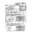
図2は、本発明の第1の実施の形態の計算機システムの構成を示すブロック図である。 FIG. 2 is a block diagram showing a configuration of the computer system according to the first embodiment of this invention.
なお、図1において既に説明した部分については、説明を省略する。 In addition, description is abbreviate | omitted about the part already demonstrated in FIG.
図2に示す計算機システムは、計算機10、ストレージシステム100、ストレージシステム200及び管理計算機500を備える。ストレージシステム100は、装置寿命が近づいている古いストレージシステムであり、計算機10によって利用される記憶領域101を格納する。ストレージシステム200は、ストレージシステム100に代わって、計算機10が新規に利用開始する新しいストレージシステムである。管理計算機500は、図2の計算機システムの運用を管理する計算機である。 The computer system shown in FIG. 2 includes a
計算機10とストレージシステム100とは、ファイバチャネルによって接続される。具体的には、計算機10のファイバチャネルインタフェース(以下FCインタフェースと略す)13が、ファイバチャネルスイッチ(以下FCスイッチと略す)20を介して、ストレージシステム100のFCインタフェース110と接続される。一方、ストレージシステム100及びストレージシステム200は、FCスイッチ30を介して、ファイバチャネルによって接続される。本実施の形態のFCスイッチ30は、計算機10及びストレージシステム100等を接続するネットワークを構成する。本発明は、ネットワークの種類に限定されないため、ファイバチャネルに代えて、インターネットプロトコルを用いるネットワークを用いても良い。 The
次に、計算機10について説明する。 Next, the
計算機10は、CPU11、メモリ12、FCインタフェース13及び管理インタフェース19を備える。 The
CPU11は、メモリ12が保持するプログラムを実行するプロセッサである。 The
メモリ12には、CPU11によって実行されるプログラム及びデータが格納される。本実施の形態のメモリ12には、アプリケーションプログラム15、パス切替プログラム50及びパス情報51が格納される。 The
アプリケーションプログラム15は、ストレージシステムに対してデータのリードライト要求を発行することによって、データの処理を実行する。 The
パス切替プログラム50は、アプリケーションプログラム15がどのストレージシステムのどの記憶領域にリードライト要求を発行するかを最終的に決定する。 The
パス情報51は、アプリケーションプログラム15が発行するリードライト命令の発行先の記憶領域を設定するテーブルである(図3参照)。 The
FCインタフェース13は、FCスイッチ20及びFCスイッチ30を介して、ストレージシステム100及びストレージシステム200に接続される。計算機10は、FCインタフェース13を介して、各ストレージシステムとリードライト要求及びデータをやり取りする。 The
管理インタフェース19は、管理ネットワーク90を介して管理計算機500と接続される。 The
次に、ストレージシステム100について説明する。 Next, the
ストレージシステム100は、FCインタフェース110、FCインタフェース115、データ転送制御モジュール120、キャッシュ121、CPU140、メモリ150、管理インタフェース190及び記憶領域101を備える。ストレージシステム100は、さらに、仮想記憶領域102を備えてもよい。 The
FCインタフェース110は、FCスイッチ20を介して計算機10と接続される。 The
FCインタフェース115は、FCスイッチ30を介して他のストレージシステム(図2の例では、ストレージシステム200)と接続される。 The
データ転送制御モジュール120は、記憶領域101及び仮想記憶領域102とFCインタフェース110等との間のデータ転送を制御する。 The data
キャッシュ121は、計算機10から受信したデータ及び記憶領域101等から読み出したデータを一時的に保持する。 The
CPU140は、メモリ150に格納されたプログラムを実行することによって、計算機10から受け付けた要求の処理、データのコピー、及び、記憶領域101等の制御等を実行する。 The
メモリ150には、CPU140によって実行されるプログラム及びそれらのプログラムの実行のために必要なテーブルが格納される。具体的には、メモリ150には、記憶領域処理プログラム151、仮想記憶領域制御プログラム152、データコピー制御プログラム153、キャッシュ制御プログラム154及び管理テーブル155が格納される。これらのプログラムは、計算機10からのリードライト要求又は管理計算機500による記憶領域101等の制御を処理するために実行される(後述)。 The
管理テーブル155は、ストレージシステム100内で実行されるデータコピーを管理するために使用される。 The management table 155 is used for managing data copies executed in the
管理インタフェース190は、管理ネットワーク90を介して管理計算機500に接続される。 The
記憶領域101は、計算機10が使用するデータを格納する領域である。例えば、ストレージシステム100は、一つ以上のハードディスクドライブ(図示省略)を備え、これらのハードディスクドライブ上に記憶領域101が設定される。計算機10は、一つの記憶領域101を一つのハードディスクドライブと認識する。 The
本実施の形態の計算機システムは、初期状態において、一つのストレージシステム100を備え、ストレージシステム100は、計算機10が使用する一つの記憶領域101を備える。しかし、本発明は、任意の数の計算機が任意の数の記憶領域を備える計算機システムにおいても、実施することができる。 The computer system of this embodiment includes one
ストレージシステム200の構成は、ストレージシステム100の構成と同様であるので、詳細な説明を省略する。 Since the configuration of the
ストレージシステム200のFCインタフェース210、FCインタフェース215、データ転送制御モジュール220、キャッシュ221、CPU240、メモリ250及び管理インタフェース290は、それぞれ、FCインタフェース110、FCインタフェース115、データ転送制御モジュール120、キャッシュ121、CPU140、メモリ150及び管理インタフェース190と同様である。 The
メモリ250に格納される記憶領域処理プログラム251、仮想記憶領域制御プログラム252、データコピー制御プログラム253、キャッシュ制御プログラム254及び管理テーブル255は、それぞれ、メモリ150に格納される記憶領域処理プログラム151、仮想記憶領域制御プログラム152、データコピー制御プログラム153、キャッシュ制御プログラム154及び管理テーブル155に対応する。 The storage
次に、管理計算機500について説明する。 Next, the
管理計算機500は、CPU510と、メモリ550及び管理インタフェース590を備える。 The
CPU510は、メモリ550に格納されたプログラムを実行する。
メモリ550には、CPU510によって実行されるプログラム及びそれらのプログラムの実行のために必要なテーブルが格納される。具体的には、メモリ550には、ストレージシステム検出プログラム551、データマイグレーションプログラム555及び管理テーブル556が格納される。 The
管理テーブル556は、ストレージシステム100等において実行されるデータ移行を管理するために使用される(図6参照)。 The management table 556 is used for managing data migration executed in the
さらに、管理計算機500には、管理者に必要な情報を提示するためのディスプレイ580、管理者からの入力を受け付けるキーボード581及びマウス582が接続される。 Further, a
次に、パス情報51について説明する。 Next, the
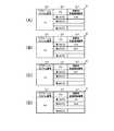
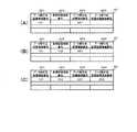
図3は、本発明の第1の実施の形態のパス情報51の説明図である。 FIG. 3 is an explanatory diagram of the
図3において、(A)から(D)は、本実施の形態の各時点におけるパス情報51を示す。これらについては、後で説明する。 In FIG. 3, (A) to (D) show
本実施の形態のパス情報51は、アプリケーションプログラム番号511、パス512及び接続先記憶領域番号513からなる。 The
アプリケーションプログラム番号511は、パス情報51によってリードライト命令の発行先が設定されるアプリケーションプログラムの番号である。図3の例では、アプリケーションプログラム15のリードライト命令の発行先が設定される。 The
パス512は、設定されるパスが何番目のパスであるかを示す。第1のパスは、現時点で設定されているパスを示す。第2のパスは、第1のパスの次に設定されるパスを示す。第nのパスは、第n−1のパスの次に設定されるパスを示す(nは任意の自然数)。 A
接続先記憶領域番号513は、設定されるパスの接続先の記憶領域の番号(識別子)である。図3(A)の例では、第1のパスに対応する接続先記憶領域番号513として、「101」が設定されている。この場合、計算機10から記憶領域101にリードライト要求が発行される。 The connection destination
次に、確認画面について説明する。 Next, the confirmation screen will be described.
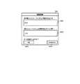
図4は、本発明の第1の実施の形態のディスプレイ580に表示される確認画面の説明図である。 FIG. 4 is an explanatory diagram of a confirmation screen displayed on the
本実施の形態の確認画面589は、新ストレージシステム表示部5891、旧ストレージシステム表示部5892、実行ボタン5893及び取り消しボタン5894からなる。 The
新ストレージシステム表示部5891には、ディスカバリの指示(61)に従って発見された新しいストレージシステムを示す情報が表示される。 The new storage
一方、旧ストレージシステム表示部5892には、装置寿命が近づいている古いストレージシステムを示す情報が表示される。 On the other hand, the old storage
図4の例では、新ストレージシステム表示部5891に「200」が、旧ストレージシステム表示部5892に「100」が表示されている。これは、ストレージシステム100の装置寿命が近づいている一方、ストレージシステム200が新たに計算機システムに接続されて、ディスカバリ指示によって発見されたことを示している。 In the example of FIG. 4, “200” is displayed on the new storage
実行ボタン5893(図4の「OK」)は、システム管理者がデータ移行を実行するときに操作(例えば、マウス582のクリック)される。図4の例では、システム管理者が実行ボタンを操作すると、ストレージシステム100からストレージシステム200へのデータ移行が開始される。 The execution button 5893 (“OK” in FIG. 4) is operated (for example, clicked on the mouse 582) when the system administrator executes data migration. In the example of FIG. 4, when the system administrator operates the execute button, data migration from the
取り消しボタン5894(図4の「CANCEL」)は、システム管理者がデータ移行を実行しないときに操作される。 A cancel button 5894 (“CANCEL” in FIG. 4) is operated when the system administrator does not execute data migration.
次に、記憶領域一覧について説明する。 Next, the storage area list will be described.
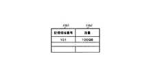
図5は、本発明の第1の実施の形態の記憶領域一覧の説明図である。 FIG. 5 is an explanatory diagram of a storage area list according to the first embodiment of this invention.
記憶領域一覧は、ストレージシステム100の記憶領域処理プログラム151(又は、ストレージシステム200の記憶領域処理プログラム251)が、管理計算機500からの要求を受けたときに作成し、管理計算機500に応答する情報である(後述)。 The storage area list is created when the storage
記憶領域一覧は、作成された時点のストレージシステム100等に設定されている記憶領域101等に関する情報を含む。本実施の形態の記憶領域一覧は、記憶領域101等を識別する記憶領域番号1561及び記憶領域101等のデータ容量を示す容量1562からなる。 The storage area list includes information related to the
図5には、例として、ストレージシステム100の記憶領域処理プログラム151が応答する記憶領域一覧を示す。図5の例では、記憶領域番号1561が「101」であり、容量1562が「100GB」である。これは、ストレージシステム100に記憶領域101が設定され、その容量が100GB(ギガバイト)であることを示す。 FIG. 5 shows a list of storage areas to which the storage
次に、管理テーブル556について説明する。 Next, the management table 556 will be described.
図6は、本発明の第1の実施の形態の管理計算機500に格納される管理テーブル556の説明図である。 FIG. 6 is an explanatory diagram of the management table 556 stored in the
管理テーブル556は、本実施の形態の計算機システム内で実行されるデータ移行を管理するテーブルである。 The management table 556 is a table for managing data migration executed in the computer system of this embodiment.
図6において、(A)及び(B)は、本実施の形態の各時点における管理テーブル556を示す。これらについては、後で説明する。 In FIG. 6, (A) and (B) show the management table 556 at each time point in the present embodiment. These will be described later.
管理テーブル556は、データ移行元記憶領域番号5561、仮想記憶領域番号5562及びデータ移行先記憶領域番号5563からなる。これらのフィールドには、いずれかの記憶領域又は仮想記憶領域を識別する記憶領域番号(識別子)が登録される。 The management table 556 includes a data migration source
ここで、記憶領域101、仮想記憶領域102及び記憶領域201の記憶領域番号は、それぞれ、「101」、「102」及び「201」である。 Here, the storage area numbers of the
図6(A)の例では、データ移行元記憶領域番号5561が「101」、データ移行先記憶領域番号5563が「201」である。これは、記憶領域101のデータが記憶領域201に移行されるように設定されていることを示す。 In the example of FIG. 6A, the data migration source
図6(B)の例では、データ移行元記憶領域番号5561が「101」、仮想記憶領域番号5562が「102」、データ移行先記憶領域番号5563が「201」である。これは、図1に示すように、記憶領域201に対応する仮想記憶領域102が設定され、記憶領域101のデータが仮想記憶領域102にコピーされることによって、そのデータが記憶領域201に移行されることを示す。 In the example of FIG. 6B, the data migration source
次に、管理テーブル155について説明する。 Next, the management table 155 will be described.
図7は、本発明の第1の実施の形態のストレージシステム100に格納される管理テーブル155の説明図である。 FIG. 7 is an explanatory diagram of the management table 155 stored in the
管理テーブル155は、ストレージシステム100内に存在する記憶領域のペアの状態を管理するテーブルである。 The management table 155 is a table for managing the state of storage area pairs existing in the
図7において、(A)及び(B)は、本実施の形態の各時点における管理テーブル155を示す。これらについては、後で説明する。 In FIG. 7, (A) and (B) show the management table 155 at each time point of the present embodiment. These will be described later.
管理テーブル155は、コピー元記憶領域番号1551、コピー先記憶領域番号1552及び状態1553からなる。 The management table 155 includes a copy source
コピー元記憶領域番号1551及びコピー先記憶領域番号1552は、それぞれ、実行されるデータコピーのコピー元及びコピー先の記憶領域(又は仮想記憶領域)の番号(識別子)である。図7の例では、記憶領域101がコピー元、仮想記憶領域102がコピー先である。すなわち、図1に示すように、記憶領域101及び仮想記憶領域102がペアを形成している。 The copy source
状態1553は、ペアの状態を示す。図7(A)の例では、状態1553は「ペア」である。これは、記憶領域101及び仮想記憶領域102にペアが形成されていることを示す。一方、図7(B)の例では、状態1553は「コピー中」である。これは、記憶領域101から仮想記憶領域102へのデータのコピーが実行されていることを示す。 A
なお、ストレージシステム200には、管理テーブル255が格納される。管理テーブル255の構成は管理テーブル155と同様であるため、説明を省略する。ただし、管理テーブル255には、ストレージシステム200内に存在するペアに関する情報が登録される。 The
次に、初期状態について説明する。 Next, the initial state will be described.
本実施の形態の計算機システムは、初期状態において、計算機10、FCスイッチ20、ストレージシステム100及び管理計算機500を備える。すなわち、計算機10のアプリケーションプログラム15は、ストレージシステム100の記憶領域101を使用している。パス情報51は、図3(A)に示すように、第1のパスとして接続先の記憶領域番号「101」を設定している。パス切替制御プログラム50は、アプリケーションプログラム15からリードライト要求を受信するたびに、このパス情報51を参照し、リードライト要求を接続先の記憶領域101に発行する。その結果、アプリケーションプログラム15が発行するリードライト要求は、FCインタフェース13を介して、記憶領域101に発行される。 The computer system of this embodiment includes a
次に、ストレージシステム100の装置寿命とストレージシステム200の設置について説明する。 Next, the apparatus life of the
ここで、ストレージシステム100の装置寿命が近づき、新しいストレージシステム200にデータを移行する場合を想定する。システム管理者等は、ストレージシステム200を設置し、FCスイッチ30を介して、ストレージシステム100のFCインタフェース125と、FCインタフェース210を接続する。さらに、システム管理者等は、ストレージシステム200の管理インタフェース290を管理ネットワーク90に接続する。 Here, it is assumed that the device life of the
次に、管理計算機500におけるストレージシステム200の検出について説明する。 Next, detection of the
管理計算機500のストレージシステム検出プログラム551は、定期的に管理ネットワーク90を検索し、接続されているストレージシステムの残稼働時間(すなわち、装置寿命までの時間)と、新しいストレージシステムが接続されたか否かを確認する。本実施の形態では、新しくストレージシステム200が発見されると、ストレージシステム検出プログラム551は、例えば、図4に示す確認画面589をディスプレイ580に表示する。その結果、新しいストレージシステム200が追加されたこと、及び、ストレージシステム100の装置寿命が近づいていることが、システム管理者に通知される。 The storage
システム管理者は、確認画面589を参照し、キーボード581又はマウス582を操作して、データ移行を実行するか否かを決定することができる。以下、確認画面589において実行ボタン5893が操作された(すなわち、システム管理者がデータ移行を実行することを決定した)場合について、図8のフローチャートを参照して説明する。 The system administrator can determine whether to execute data migration by referring to the
図8は、本発明の第1の実施の形態のデータマイグレーションプログラム555が実行するデータマイグレーションの手順を示すフローチャートである。 FIG. 8 is a flow chart showing a data migration procedure executed by the
確認画面589において実行ボタン5893が操作されると、管理計算機500は、データマイグレーションプログラム555(以下、DMプログラム555と記載する)を実行する。以下、DMプログラム555が実行する処理を、図8のフローチャートを参照して説明する。 When the
DMプログラム555は、まず、ストレージシステム100から、記憶領域一覧を入手する(802)。本実施の形態では、DMプログラム555がストレージシステム100の記憶領域処理プログラム151に記憶領域一覧を要求する。記憶領域処理プログラム151は、この要求に対して、図5に示す記憶領域一覧を応答する。 The
次に、DMプログラム555は、ストレージシステム200に対して、記憶領域101のデータの移行先として、記憶領域101の容量に対応する記憶領域を作成するように指示する(804)。図5の記憶領域一覧が示すように、記憶領域101の容量は「100GB」である。このため、DMプログラム555は、ストレージシステム200の記憶領域制御プログラム251に対して、100GBの記憶領域を作成するように指示する。記憶領域制御プログラム251は、記憶領域201を作成する(図2参照)。記憶領域制御プログラム251は、記憶領域201を作成したことをDMプログラム555に通知する。 Next, the
次に、DMプログラム555は、記憶領域101に対応する記憶領域201を作成したことを管理テーブル556に登録する(806)。この時点の管理テーブル556の内容は、図6(A)に示す通りである。すなわち、データ移行元記憶領域番号5561に登録されている記憶領域101の記憶領域番号「101」に対応して、データ移行先記憶領域番号5563に記憶領域201の記憶領域番号「201」が登録される。 Next, the
次に、DMプログラム555は、ストレージシステム100のFCインタフェース115をイニシエータとして設定する(808)。その結果、ストレージシステム100は、FCインタフェース115を介して、ストレージシステム200にリードライト要求を発行できるようになる。 Next, the
次に、DMプログラム555は、ストレージシステム200のFCインタフェース210をターゲットとして設定する(810)。その結果、ストレージシステム200は、FCインタフェース210を介して、ストレージシステム100からのリードライト要求を受信できるようになる。 Next, the
次に、DMプログラム555は、仮想記憶領域制御プログラム152に対して、イニシエータとして設定されたFCインタフェース115を介して、記憶領域をディスカバリ(発見)するように指示する(812)。ここでは、記憶領域201がディスカバリされる。仮想記憶領域制御プログラム152は、記憶領域201が見つかったことを、DMプログラム555に通知する。 Next, the
次に、DMプログラム555は、仮想記憶領域制御プログラム152に対して、記憶領域201に対応する仮想記憶領域を作成するように指示する(814)。仮想記憶領域制御プログラム152は、仮想記憶領域102を作成する(図2参照)。仮想記憶領域制御プログラム152は、記憶領域201に対応する仮想記憶領域102を作成したことをDMプログラム555に通知する。 Next, the
次に、DMプログラム555は、管理テーブル556を更新する(816)。具体的には、DMプログラム555は、管理テーブル556に、記憶領域201に対応する仮想記憶領域102を登録する。更新された管理テーブル556の内容は、図6(B)に示す通りである。仮想記憶領域102に対するリードライト要求(データのコピー時に発行される要求を含む)は、イニシエータとして設定されたFCインタフェース115を介して、ストレージシステム200の記憶領域201に発行される。すなわち、仮想記憶領域102に対するリードライト要求は、実際には、記憶領域201へのリードライト要求に変換されて再発行される。その結果、仮想記憶領域102に対するライト要求に応じて記憶領域201にデータがライト(書き込み)され、仮想記憶領域102に対するリード要求に応じて記憶領域201からデータがリード(読み出し)される。 Next, the
次に、DMプログラム555は、管理テーブル556に登録された記憶領域番号を参照して、データコピー制御プログラム153に対して、記憶領域101をデータコピー元、仮想記憶領域102をデータコピー先とするペアを設定するよう指示する(818)。このペア設定によって、データをコピーする準備が整う。データコピー制御プログラム153は、このペア設定を、管理テーブル155に登録する。さらに、データコピー制御プログラム153は、管理テーブル155を使用して、設定されたペアの状態を管理する。ステップ818が実行された直後の管理テーブル155の内容は、図7(A)に示す通りである。 Next, the
次に、DMプログラム555は、キャッシュ制御プログラム154に対して、記憶領域101に関するキャッシュ121の利用を禁止するよう指示する(820)。キャッシュ制御プログラム154は、キャッシュ121に残っている記憶領域101に関するデータを全て記憶領域101に書き込むとともに、以後、キャッシュ121を利用しない設定とする。 Next, the
キャッシュ121の中に計算機から受け取ったデータがあり、そのデータがまだ記憶領域101に書き込まれていないと、ストレージシステム100とストレージシステム200の記憶領域のデータが完全に一致しない。コピー完了後にパスを切り替える際に、記憶領域のデータが一致している必要がある。このため、ステップ820においてキャッシュ121の利用を禁止しておく。キャッシュ121を利用禁止とすると、計算機に対する応答時間が長くなるので、コピー完了後、パスを切り替える直前にキャッシュ121を利用禁止にしても良い。 If there is data received from the computer in the
次に、DMプログラム555は、計算機10のパス切替プログラム50に対して、記憶領域101に関連する第2のパスとして、記憶領域201を登録するように指示する(822)。その結果、パス情報51は、図3(B)に示すように更新される。 Next, the
次に、DMプログラム555は、データコピー制御プログラム153に対して、コピーを開始するように指示する(824)。データコピー制御プログラム153は、記憶領域101から仮想記憶領域102にデータのコピーを開始する。このとき、データコピー制御プログラム153は、管理テーブル155において、記憶領域101と仮想記憶領域102のペアに対応する状態1553を「コピー中」に書き換える(図7(B)参照)。 Next, the
データのコピーとは、データ転送制御モジュール120が、コピー元の記憶領域(本実施の形態では、記憶領域101)の先頭のブロックから最終のブロックまでを順次読み出し、コピー先の記憶領域(本実施の形態では、仮想記憶領域102)の同じブロック位置に書き込むことである。データのコピー中に計算機10からデータのライト要求を受信した場合、データ転送制御モジュール120は、コピー元の記憶領域101とコピー先の仮想記憶領域102の両方にデータを書き込んでも良い。あるいは、データ転送制御モジュール120は、コピー元の記憶領域101にのみデータを書き込み、書き込みのあったブロックの位置を記憶し、最終ブロックまでコピーした後に、記憶していたブロック位置のデータを再度コピーしてもよい。 Data copy means that the data
本実施の形態では、コピー先が仮想記憶領域102である。このため、コピーの際、データが仮想記憶領域102に書き込まれると、仮想記憶領域処理プログラムは、その書き込みを記憶領域201に対するライト要求として、FCインタフェース115を介して発行する。 In this embodiment, the copy destination is the
コピーが完了すると、データコピー制御プログラム153は、コピーの完了をDMプログラム555に通知する。 When the copying is completed, the data copy
次に、DMプログラム555は、計算機10のパス切替プログラム50に対して、パス情報51の第1のパスとして記憶領域201を設定するように指示する(826)。パス切替プログラム50は、パス情報51を、図3(C)に示すように更新する。パス情報51が更新されると、それ以後、アプリケーションプログラム15が発行するリードライト要求は、パス切替ソフトウエア50によって、データの移行が完了した新しい記憶領域201に発行される。パス切替ソフトウエア50は、パス情報51の更新を完了すると、DMプログラム555に、その完了を通知する。 Next, the
次に、DMプログラム555は、データコピー制御プログラム153に対して、記憶領域101と仮想記憶領域201のペア関係を解除するよう指示する(828)。さらに、DMプログラム555は、仮想記憶領域制御プログラム152に対して、記憶領域201と仮想記憶領域102との対応を解除するように指示する(830)。 Next, the
以上の第1の実施の形態によれば、記憶領域101から記憶領域201へのデータの移行を、計算機10からのリードライト要求の受付を中断することなく実行することができる。これは、計算機10と記憶領域101との接続関係とは独立に仮想記憶領域102と記憶領域201の接続関係を確立できること、記憶領域101から仮想記憶領域102へのデータのコピーを計算機10からの要求を受け付けながら実行できること、及び、記憶領域101から記憶領域201へのパス切替を要求毎に実行できることによって実現される。 According to the first embodiment described above, data migration from the
以上の手順の完了後、さらに、DMプログラム555は、FCインタフェース210をイニシエータとして設定し、FCインタフェース215をターゲットとして設定してもよい(832)。 After completion of the above procedure, the
次に、DMプログラム555は、ストレージシステム200の仮想記憶領域制御プログラム252に対して、イニシエータとして設定されたFCインタフェース210を介して、記憶領域をディスカバリ(発見)するように指示してもよい(834)。図2の構成では、このとき、記憶領域101がディスカバリされる。 Next, the
次に、DMプログラム555は、仮想記憶領域制御プログラム252に対して、記憶領域101に対応する仮想記憶領域(図示省略)を作成するよう指示してもよい(836)。その結果、計算機10は、ストレージシステム200を経由して、記憶領域101を再利用することができる。これによって、まもなく寿命を迎えるストレージシステムであっても、データ移行完了後、装置寿命が到来する直前まで使用することができ、記憶領域の有効利用を図ることができる。このような記憶領域の使用は一時的なものであることが望ましい。 Next, the
<第2の実施の形態>
第2の実施の形態においては、図9に示すように(後述)、第1の実施の形態のファイバチャネルに代えて、インターネットプロトコルによるネットワークが計算機10、ストレージシステム100及びストレージシステム200を接続している。インターネットプロトコルに対応するため、第1の実施の形態のFCスイッチ20等に代えてIPスイッチ21が、FCインタフェース13等に代えてIPインタフェース14等が用いられる。また、第1の実施の形態では、計算機10のパス切替プログラム50が、アプリケーションプログラム15が発行するリードライト要求の発行先記憶領域を切り替えていたが、第2の実施の形態では、IPスイッチがこの切り替えを実現する。<Second Embodiment>
In the second embodiment, as shown in FIG. 9 (described later), instead of the fiber channel of the first embodiment, a network based on the Internet protocol connects the
最初に、本実施の形態の計算機システムの構成について説明する。 First, the configuration of the computer system of this embodiment will be described.
図9は、本発明の第2の実施の形態の計算機システムの構成を示すブロック図である。 FIG. 9 is a block diagram showing a configuration of a computer system according to the second embodiment of this invention.
本実施の形態の計算機システムは、第1の実施の形態の計算機システム(図2)の2台のFCスイッチ20及び30に代えて、一台のIPスイッチ21を備える。さらに、本実施の形態の計算機システムは、FCインタフェース13、110、115、210及び215に代えて、IPインタフェース14、111、116、211、216を備える。さらに、本実施の形態の計算機10は、パス切替ソフトウエア50及びパス情報51を保持しない。 The computer system of this embodiment includes a
その他の部分については、第1の実施の形態(図2)と同様であるため、説明を省略する。 Since other parts are the same as those in the first embodiment (FIG. 2), the description thereof is omitted.
次に、IPスイッチ21について説明する。 Next, the
本実施の形態におけるパス切替は、IPスイッチ21が備えるパス切替モジュール25が実行する。パス切替モジュール25は、計算機10から受信したリードライト要求を含むパケットを解析し、パス情報26に従ってパケットを書き換えることによって、パケットの送付先を切り替える。パケットの発行元及び発行先は、IPアドレス及びポート番号等、IPインタフェースの識別情報によって識別される。以下の説明では、便宜上、図中に表示する番号を用いてパケットの発行元及び発行先を識別する。具体的には、以下の説明において、IPアドレスの代わりに、IPインタフェースに付した番号(14、111等)を使用し、ポート番号の代わりに、アプリケーションプログラムに付した番号(15)又は記憶領域に付した番号(101等)を使用する。 The path switching in the present embodiment is executed by the
次に、パス情報26について説明する。 Next, the
図10は、本発明の第2の実施の形態のパス情報26の説明図である。 FIG. 10 is an explanatory diagram of the
図10において、(A)から(C)は、本実施の形態の各時点におけるパス情報26を示す。これらについては、後で説明する。 In FIG. 10, (A) to (C) show
パス情報26は、発行元(ソース)261、発行先(ディスティネーション)262、書換ビット263及び書換発行先264からなる。 The
発行元261は、パケットの発行元を識別するIPアドレス2611及びポート番号2612からなる。 The
発行先262は、パケットの発行先を識別するIPアドレス2621及びポート番号2622からなる。 The
書換ビット262は、パケットの発行先を書換発行先264に書き換えるか否かを示すフラグである。書換ビット262が「1」であるとき、パス切替モジュール25は、パケットの発行元及び発行先がそれぞれ発行元261及び発行先262と一致するか否かを判定し、これらが一致するとき、パケットの発行先を書換発行先264に書き換える。 The
書換発行先264は、書き換えられた後のパケットの発行先を識別するIPアドレス2641及びポート番号2642からなる。 The
アプリケーションプログラム15が発行したリードライト要求のパケットには、発行元として、IPアドレス「14」(IPインタフェース14を意味する)、ポート番号「15」(アプリケーションプログラム15を意味する)が、発行先として、IPアドレス「111」(IPインタフェース111を意味する)、ポート番号「101」(記憶領域101を意味する)が含まれている。これらは、それぞれ、図10に示す発行元261の2611及びポート番号2612、及び、発行先262の2621及びポート番号2622と一致する。書換ビットが「1」である場合、IPスイッチ21のパス切替モジュール25は、そのパケットの発行先のIPアドレス及びポート番号を書換発行先264のIPアドレス2641及びポート番号2642に書き換える。 In the read / write request packet issued by the
次に、データマイグレーション手順について説明する。 Next, a data migration procedure will be described.
データマイグレーション(移行)の手順は、基本的に第1の実施の形態と同様である(図8参照)。ただし、計算機10のパス切替プログラム50に対する指示は、第2の実施の形態においては、IPスイッチ21のパス切替モジュール25への指示となる。以下、第1の実施の形態との相違点のみ説明する。 The data migration procedure is basically the same as that of the first embodiment (see FIG. 8). However, the instruction to the
なお、本実施の形態において、図8の手順が開始した直後のパス情報26の内容は、図10(A)に示す通りである。 In the present embodiment, the contents of the
ステップ822において、DMプログラム555は、IPスイッチ21のパス切替モジュール25に対して、書換発行先264のIPアドレス2641の値として「216」、ポート番号2642の値として「201」を保持するように指示する。その結果、パス情報26は、図10(B)に示すように更新される。 In
ステップ826において、DMプログラム555は、IPスイッチ21のパス切替モジュール25に対して、書換ビット262を「1」にするよう指示する。その結果、パス情報26は、図10(C)に示すように更新される。 In
以上の第2の実施の形態によれば、データ移行の完了後、計算機10のアプリケーションプログラム15が今までどおり記憶領域101にリードライト要求を発行しても、IPスイッチ21のパス切替制御モジュール25によって、そのリードライト要求は記憶領域201に発行される。 According to the second embodiment described above, even after the data migration is completed, even if the
<第3の実施の形態>
次に、第3の実施の形態を、図面を参照して説明する。<Third Embodiment>
Next, a third embodiment will be described with reference to the drawings.
図11は、本発明の第3の実施の形態の計算機システムの構成を示すブロック図である。 FIG. 11 is a block diagram illustrating a configuration of a computer system according to the third embodiment of this invention.
第3の実施の形態の計算機システムの構成(図10)は、基本的に、第1の実施の形態の計算機システム(図2)と同じである。ただし、第3の実施の形態のストレージシステム200は、さらに、記憶領域切替プログラム259及び仮想記憶領域202を備える。また、第3の実施の形態の管理計算機500のメモリ550には、管理テーブル557が格納される(図12参照)。 The configuration of the computer system according to the third embodiment (FIG. 10) is basically the same as that of the computer system according to the first embodiment (FIG. 2). However, the
第1の実施の形態では、ストレージシステム100がストレージシステム200の記憶領域201に対応する仮想記憶領域102を作成していた。第3の実施の形態では、さらに、ストレージシステム200がストレージシステム100の記憶領域101に対応する仮想記憶領域202を作成して、データをコピーする。 In the first embodiment, the
最初に、管理テーブル557について説明する。 First, the management table 557 will be described.
図12は、本発明の第3の実施の形態の管理計算機500に格納される管理テーブル557の説明図である。 FIG. 12 is an explanatory diagram of the management table 557 stored in the
管理テーブル557は、本実施の形態の計算機システム内で実行されるデータ移行を管理するテーブルである。 The management table 557 is a table for managing data migration executed in the computer system of this embodiment.
図12において、(A)から(C)は、本実施の形態の各時点における管理テーブル557を示す。これらについては、後で説明する。 In FIG. 12, (A) to (C) show the management table 557 at each time point in the present embodiment. These will be described later.
管理テーブル557は、データ移行元記憶領域番号5571、仮想記憶領域番号5572、データ移行先記憶領域番号5573及びデータ移行先仮想記憶領域番号5574からなる。これらのうち、データ移行元記憶領域番号5571、仮想記憶領域番号5572及びデータ移行先記憶領域番号5573は、それぞれ、管理テーブル556のデータ移行元記憶領域番号5561、仮想記憶領域番号5562及びデータ移行先記憶領域番号5563(図6参照)と同様である。また、図12(A)及び(B)が示す状態は、それぞれ、図6(A)及び(B)が示す状態と同様である。このため、これらについては説明を省略する。なお、仮想記憶領域202の記憶領域番号(識別子)は、「202」である。 The management table 557 includes a data migration source
図12(C)の例では、データ移行元記憶領域番号5571が「101」、仮想記憶領域番号5572が「102」、データ移行先記憶領域番号5573が「201」、データ移行先仮想記憶領域番号5574が「202」である。これは、図11に示すように、記憶領域201に対応する仮想記憶領域102及び記憶領域101に対応する仮想記憶領域202が設定され、仮想記憶領域202に書き込まれたデータは、記憶領域101、仮想記憶領域102を経由して記憶領域201に移行されることを示す(後述)。 In the example of FIG. 12C, the data migration source
次に、本実施の形態におけるデータの流れについて説明する。 Next, the data flow in this embodiment will be described.
図11に示す計算機システムにおいて、計算機10からライト要求によって記憶領域101に書き込まれるデータは、記憶領域101に書き込まれた後、仮想記憶領域102にコピーされる。仮想記憶領域102へのライト要求は、記憶領域201へのライト要求に変換されて再発行される。その結果、仮想記憶領域102にコピーされたデータは、記憶領域201に書き込まれる。 In the computer system shown in FIG. 11, data written to the
一方、計算機10から仮想記憶領域202にライト要求が発行されると、そのライト要求は、記憶領域101へのライト要求に変換されて再発行される。その結果、記憶領域101にデータが書き込まれる。記憶領域101に書き込まれたデータは、仮想記憶領域102にコピーされる。仮想記憶領域102へのライト要求は、記憶領域201へのライト要求に変換されて再発行される。その結果、仮想記憶領域102にコピーされたデータは、記憶領域201に書き込まれる。 On the other hand, when a write request is issued from the
第1の実施の形態では、コピーが完了するまで、計算機10でのパスの切り替えを行うことができなかった。このため、第1の実施の形態のパス切替ソフトウエア50は、コピーの完了を正しく把握する必要があった。しかし、第3の実施の形態によれば、以上のように、計算機10が記憶領域101にライト要求を発行しても、仮想記憶領域202にライト要求を発行しても、結果として、必ず記憶領域201にデータが書き込まれる。このため、本実施の形態のパス切替ソフトウエア50は、ストレージシステムのコピーの状態に関係なく、パスをいつでも切り替えることができる。 In the first embodiment, the path cannot be switched in the
以下、本実施の形態のデータマイグレーション手順について、図13のフローチャートを参照して説明する。 Hereinafter, the data migration procedure of the present embodiment will be described with reference to the flowchart of FIG.
図13は、本発明の第3の実施の形態のデータマイグレーションプログラム555が実行するデータマイグレーションの手順を示すフローチャートである。 FIG. 13 is a flowchart illustrating a data migration procedure executed by the
なお、図13において、第1の実施の形態のデータマイグレーション(図8参照)と同様の手順については、詳細な説明を省略する。 In FIG. 13, a detailed description of the same procedure as the data migration (see FIG. 8) of the first embodiment is omitted.
第1の実施の形態と同様に、確認画面589において実行ボタン5893が操作されると、管理計算機500は、DMプログラム555を実行する。 Similar to the first embodiment, when the
DMプログラム555は、まず、ストレージシステム100から、記憶領域一覧を入手する(1302)。本実施の形態では、ストレージシステム100の記憶領域処理プログラム151が、DMプログラム555からの要求に対して、図5に示す記憶領域一覧を応答する。 The
次に、DMプログラム555は、ストレージシステム200に対して、記憶領域101の容量に対応する記憶領域を作成するように指示する(1304)。記憶領域制御プログラム251は、記憶領域201を作成し(図11)、作成したことをDMプログラム555に通知する。 Next, the
DMプログラム555は、記憶領域101に対応する記憶領域201を作成したことを管理テーブル557に登録する(1306)。この時点の管理テーブル557の内容は、図12(A)に示す通りである。 The
次に、DMプログラム555は、ストレージシステム100のFCインタフェース115をイニシエータとして設定する(1308)。次に、DMプログラム555は、ストレージシステム200のFCインタフェース210をターゲットとして設定する(1310)。 Next, the
さらに、DMプログラム555は、FCインタフェース215をイニシエータとして設定する(1312)。その結果、ストレージシステム200は、FCインタフェース215を介して、ストレージシステム100にリードライト要求を発行できるようになる。 Further, the
次に、DMプログラム555は、仮想記憶領域制御プログラム152に対して、イニシエータとして設定されたFCインタフェース115を介して、記憶領域をディスカバリ(発見)するように指示する(1314)。ここでは、記憶領域201がディスカバリされる。仮想記憶領域制御プログラム152は、記憶領域201が発見されたことを、DMプログラム555に通知する。 Next, the
次に、DMプログラム555は、仮想記憶領域制御プログラム152に対して、記憶領域201に対応する仮想記憶領域を作成するように指示する(1316)。仮想記憶領域制御プログラム152は、仮想記憶領域102を作成する(図11参照)。仮想記憶領域制御プログラム152は、記憶領域201に対応する仮想記憶領域102を作成したことをDMプログラム555に通知する。 Next, the
次に、DMプログラム555は、管理テーブル557を更新する(1318)。更新された管理テーブル557の内容は、図12(B)に示す通りである。 Next, the
次に、DMプログラム555は、仮想記憶領域制御プログラム252に対して、イニシエータとして設定されたFCインタフェース225を介して、記憶領域をディスカバリ(発見)するように指示する(1320)。ここでは、記憶領域101及び仮想記憶領域102がディスカバリされる。仮想記憶領域制御プログラム252は、記憶領域101及び仮想記憶領域102が発見されたことを、DMプログラム555に通知する。 Next, the
次に、DMプログラム555は、図12に示す管理テーブル557を参照して、発見されたものが記憶領域であるか仮想記憶領域であるかを判別する(1322)。図12(B)に示すように、発見された記憶領域101は、通常の(仮想記憶領域でない)記憶領域である。 Next, the
次に、DMプログラム555は、仮想記憶領域制御プログラム252に対して、記憶領域101に対応する仮想記憶領域を作成するように指示する(1324)。仮想記憶領域制御プログラム252は、仮想記憶領域202を作成する(図11参照)。仮想記憶領域制御プログラム252は、記憶領域101に対応する仮想記憶領域202を作成したことをDMプログラム555に通知する。 Next, the
次に、DMプログラム555は、管理テーブル557を更新する(1326)。更新された管理テーブル557の内容は、図12(C)に示す通りである。 Next, the
次に、DMプログラム555は、データコピー制御プログラム153に対して、記憶領域101をデータコピー元、仮想記憶領域を102をデータコピー先とするペアを設定するよう指示する(1328)。データコピー制御プログラム153は、このペア設定を、管理テーブル155に登録する(図7(A)参照)。 Next, the
次に、DMプログラム555は、キャッシュ制御プログラム154に対して、記憶領域101に関するキャッシュ121の利用を禁止するよう指示する(1330)。キャッシュ制御プログラム154は、キャッシュ121に残っている記憶領域101に関するデータを全て記憶領域101に書き込むとともに、以後、キャッシュ121を利用しない設定とする。 Next, the
次に、DMプログラム555は、計算機10のパス切替プログラム50に対して、記憶領域101に関連する第2のパスとして、記憶領域202を登録するように指示する(1332)。その結果、パス情報51は、図3(D)に示すように更新される。 Next, the
パス切替プログラム50は、第1の実施の形態とは異なり、パス情報51に第2のパスが設定された後、任意のタイミングでパスを切り替えることができる。図13には、説明の便宜上、第2のパスを設定した(1332)後、コピーを開始する(1334)前に、パスの切り替えを実行する(1342)手順を示す。しかし、パス切替プログラム50は、コピーを開始した後、コピーが終了する前にパスを切り替えてもよいし、コピーが終了した後でパスを切り替えてもよい。あるいは、記憶領域の切り替え(1336)(後述)の後でパスを切り替えてもよい。パス切替プログラム50は、例えば、アプリケーションプログラム15の動作状況に応じてパスを切り替えても良い。パスの切り替えの手順は、第1の実施の形態のステップ826(図8参照)と同様である。 Unlike the first embodiment, the
次に、DMプログラム555は、データコピー制御プログラム153に対して、コピーを開始するように指示する(1334)。データコピー制御プログラム153は、コピーが完了すると、コピーの完了をDMプログラム555に通知する。 Next, the
次に、DMプログラム555は、ストレージシステム200の記憶領域切替プログラム259に対して、記憶領域201の記憶領域番号(識別子)を「201」から「202」に変更するように指示する(1336)。以後、ストレージシステム200のデータ制御モジュール220は、記憶領域201を記憶領域番号「202」の記憶領域として扱う。その結果、計算機が仮想記憶領域202に対して発行した書き込み要求によって、記憶領域201にデータが書き込まれる。一方、仮想記憶領域202には、当面、記憶領域番号として「NULL」を与える。「NULL」は、この仮想記憶領域が計算機10から利用できないことを示す。 Next, the
DMプログラム555は、計算機10のパス切替ソフトウエア50からパスを切り替えた旨の通知を受信すると、データコピー制御プログラム153に対して、記憶領域101と仮想記憶領域201のペア関係を解除するように指示する(1338)。ただし、データコピーが完了する前にパスが切り替えられた場合、DMプログラム555は、データコピーが完了した後で、ペア関係の解除を指示する。 When the
次に、DMプログラム555は、記憶領域切替プログラム259に対して、記憶領域番号に「NULL」を与えた仮想記憶領域202に新たな記憶領域番号を与えるように指示する(1340)。記憶領域切替プログラム259は、例えば、仮想記憶領域202にまだ使用されていない記憶領域番号「203」を与える。その結果、計算機10は、仮想記憶領域202を記憶領域番号「203」の記憶領域として使用することができる。すなわち、ストレージシステム200は、記憶領域番号「203」を使用して、計算機10から書き込み要求又は読み出し要求を受ける。これらの要求は、ストレージシステム200内では、仮想記憶領域202に対する要求として処理される。このとき、仮想記憶領域202に対応する実際の記憶領域は、ストレージシステム100の記憶領域101である。 Next, the
以上の本発明の第3の実施の形態によれば、第1の実施の形態においては、コピーが完了する前に、パス切替プログラム50がパスを切り替えることができなかったのに対して、任意のタイミングでパスを切り替えることができる。また、ストレージシステム200が仮想記憶領域202に新たな記憶領域番号を与えることで、記憶領域101をストレージシステム200の記憶領域として再利用することができる。このため、まもなく装置寿命が到来するストレージシステムであっても、データ移行完了後、装置寿命が到来する直前まで使用することができ、記憶領域の有効利用を図ることができる。このような記憶領域の使用は、一時的なものであることが望ましい。 According to the third embodiment of the present invention described above, in the first embodiment, the
上記の実施の形態によれば、古いストレージシステムが計算機と新しいストレージシステムとの両方にネットワークを介して接続可能であるような計算機を含む計算機システムにおいて、計算機からストレージシステムへのアクセスを停止せずにデータの移行をすることができる。上記の実施の形態によれば、ストレージシステムにおけるデータ移行完了のタイミングによらず、計算機における接続パスの切り替えを行うことができる。上記の実施の形態によれば、データの移行完了後、計算機が新しいストレージシステムを経由して古いストレージシステムを継続的に利用することによって、記憶領域の有効利用を図ることができる。 According to the above embodiment, in a computer system including a computer in which an old storage system can be connected to both a computer and a new storage system via a network, access from the computer to the storage system is not stopped. You can migrate data. According to the above embodiment, the connection path in the computer can be switched regardless of the timing of completion of data migration in the storage system. According to the above embodiment, after the data migration is completed, the computer continuously uses the old storage system via the new storage system, so that the storage area can be effectively used.
10 計算機
11、140、240、510 CPU
12、150、250、550 メモリ
13、110、115、210、215 FCインタフェース
14、111、116、211、216 IPインタフェース
15 アプリケーションプログラム
19、29、190、290 管理インタフェース
20、30 FCスイッチ
21 IPスイッチ
25 パス切替モジュール
26、51 パス情報
50 パス切替プログラム
90 管理ネットワーク
100、200 ストレージシステム
101、201 記憶領域
102、202 仮想記憶領域
120、220 データ転送制御モジュール
121、221キャッシュ
151、251 記憶領域制御プログラム
152、252 仮想記憶領域制御プログラム
153、253 データコピー制御プログラム
154、254 キャッシュ制御プログラム
155、255 管理テーブル
259 記憶領域切替プログラム
500 管理計算機
551 ストレージシステム検出プログラム
555 データマイグレーションプログラム(DMプログラム)
556、557 管理テーブル
580 ディスプレイ
581 キーボード
582 マウス10
12, 150, 250, 550
556, 557 Management table 580
Claims (17)
Translated fromJapanese前記複数のストレージシステムのうち第1ストレージシステムは、
第1FCインタフェースと、第2FCインタフェースと、第1CPUと、第1メモリと、第1管理インタフェースと、第1キャッシュと、第1データ転送モジュールと、を備え、
前記第1メモリに格納されたプログラムを前記第1CPUが実行することによって実現される第1記憶領域処理部と、第1仮想記憶領域処理部と、第1データコピー制御部と、第1キャッシュ制御部と、を備え、
前記計算機によって書き込まれたデータを格納する第1記憶領域を備え、
前記複数のストレージシステムのうち第2ストレージシステムは、
第3FCインタフェースと、第4FCインタフェースと、第2CPUと、第2メモリと、第2管理インタフェースと、第2キャッシュと、第2データ転送モジュールと、を備え、
前記第2メモリに格納されたプログラムを前記第2CPUが実行することによって実現される第2記憶領域処理部と、第2仮想記憶領域処理部と、第2データコピー制御部と、第2キャッシュ制御部と、記憶領域切替部と、を備え、
前記第1記憶領域のデータが移行する第2記憶領域を備え、
前記計算機は、
第5FCインタフェースと、第3管理インタフェースと、第3CPUと、第3メモリと、を備え、
前記第3メモリに格納されたプログラムを前記第3CPUが実行することによって実現されるアプリケーション部と、経路切替部と、を備え、
前記管理計算機は、
第4管理インタフェースと、第4CPUと、第4メモリと、を備え、
前記第4メモリに格納されたプログラムを前記第4CPUが実行することによって実現されるストレージシステム検出部と、データ移行部と、を備え、
前記データ移行部は、前記第1仮想記憶領域処理部に、前記第2記憶領域に対応する第1仮想記憶領域を前記第1ストレージシステムに作成することを指示し、
前記第1仮想記憶領域処理部は、前記第1仮想記憶領域に対して発行されたデータの書き込み要求を、前記第2記憶領域に対する書き込み要求に変換して発行し、
前記データ移行部は、前記第1データコピー制御部に、前記第1記憶領域に格納された前記データを前記第1仮想記憶領域に複写することを指示し、
前記第1データコピー制御部は、前記第1記憶領域に格納された前記データを前記第1仮想記憶領域に複写するための書き込み要求を発行し、
前記データ移行部は、前記第2仮想記憶領域処理部に、前記第1記憶領域に対応する第2仮想記憶領域を前記第2ストレージシステムに作成することを指示し、
前記第2仮想記憶領域処理部は、前記第2仮想記憶領域に対して発行されたデータの書き込み要求を、前記第1記憶領域に対する書き込み要求に変換して発行し、
前記データ移行部は、前記経路切替部に、前記計算機がデータの書き込み要求を発行する対象を前記第1記憶領域から前記第2仮想記憶領域に切り替えることを指示し、
前記データ移行部は、前記記憶領域切替部に、前記複写が終了した後、前記第2記憶領域の識別子を、前記第2仮想記憶領域の識別子に変更することを指示し、
前記データ移行部は、前記記憶領域切替部に、前記第2記憶領域の識別子を前記第2仮想記憶領域の識別子に変更し、かつ、前記経路切替部が前記データを書き込む対象を前記第1記憶領域から前記第2仮想記憶領域に切り替えた後、前記第2仮想記憶領域の識別子を変更することを指示し、
前記データ移行部は、前記複写を指示する前に、前記第1キャッシュ制御部に、前記第1キャッシュに格納されている前記第1記憶領域に書き込まれるべきデータを前記第1記憶領域に書き込むことを指示し、前記第1キャッシュ制御部に、前記複写が開始された後、前記第1記憶領域に書き込まれるべきデータを前記第1キャッシュに書き込まないことを指示すること特徴とする計算機システム。In a computer system comprising: a computer; a plurality of storage systems connected to the computer via an FC switch; and a management computer that manages the computer and the plurality of storage systems.
The first storage system among the plurality of storage systems is
A first FC interface, a second FC interface, a first CPU, a first memory, a first management interface, a first cache, and a first data transfer module;
A first storage area processing unit, a first virtual storage area processing unit, a first data copy control unit, and a first cache control realized by the first CPU executing a program stored in the first memory And comprising
A first storage area for storing data written by the computer;
A second storage system of the plurality of storage systems is
A third FC interface, a fourth FC interface, a second CPU, a second memory, a second management interface, a second cache, and a second data transfer module;
A second storage area processing unit, a second virtual storage area processing unit, a second data copy control unit, and a second cache control realized by the second CPU executing the program stored in the second memory And a storage area switching unit,
A second storage area to which data of the first storage area is transferred;
The calculator is
A fifth FC interface, a third management interface, a third CPU, and a third memory;
An application unit realized by the third CPU executing a program stored in the third memory; and a path switching unit.
The management computer is
A fourth management interface, a fourth CPU, and a fourth memory;
A storage system detection unit realized by the fourth CPU executing a program stored in the fourth memory, and a data migration unit,
The data migration unit instructs the first virtual storage area processing unit to create a first virtual storage area corresponding to the second storage area in the first storage system;
The first virtual storage area processing unit converts a data write request issued to the first virtual storage area into a write request to the second storage area and issues the request.
The data migration unit instructs the first data copy control unit to copy the data stored in the first storage area to the first virtual storage area;
The first data copy control unit issues a write request for copying the data stored in the first storage area to the first virtual storage area;
The data migration unit instructs the second virtual storage area processing unit to create a second virtual storage area corresponding to the first storage area in the second storage system;
The second virtual storage area processing unit converts a data write request issued to the second virtual storage area into a write request to the first storage area and issues it,
The data migration unit instructs the path switching unit to switch a target from which the computer issues a data write request from the first storage area to the second virtual storage area,
The data migration unit instructs the storage area switching unit to change the identifier of the second storage area to the identifier of the second virtual storage area after the copying is completed;
The data migration unit changes the identifier of the second storage area to the identifier of the second virtual storage area in the storage area switching unit, and the path switching unit writes the data to the first storage. Instructing to change the identifier of the second virtual storage area after switching from the area to the second virtual storage area;
The data migration unit writes, in the first storage area, data to be written in the first storage area stored in the first cache, before instructing the copying. And instructing the first cache control unit not to write data to be written to the first storage area to the first cache after the copying is started.
前記複数のストレージシステムのうち第1ストレージシステムは、
仮想記憶領域処理部と、データコピー制御部と、前記計算機によって書き込まれたデータを格納する第1記憶領域を備え、
前記複数のストレージシステムのうち第2ストレージシステムは、前記第1記憶領域に格納されたデータが移行する第2記憶領域を備え、
前記仮想記憶領域処理部は、
前記第2記憶領域に対応する仮想記憶領域を前記第1ストレージシステムに作成し、
前記仮想記憶領域に対して発行されたデータの書き込み要求を、前記第2記憶領域に対する書き込み要求に変換して発行し、
前記データコピー制御部は、前記第1記憶領域に格納された前記データを前記仮想記憶領域に複写するための書き込み要求を発行し、
前記計算機は、経路切替部を備え、
前記経路切替部は、前記複写が終了した後、前記計算機がデータの書き込み要求を発行する対象を、前記第1記憶領域から前記第2記憶領域に切り替えることを特徴とする計算機システム。In a computer system comprising a computer and a plurality of storage systems connected to the computer,
The first storage system among the plurality of storage systems is
A virtual storage area processing unit, a data copy control unit, and a first storage area for storing data written by the computer;
The second storage system of the plurality of storage systems includes a second storage area to which data stored in the first storage area is transferred,
The virtual storage area processing unit
Creating a virtual storage area corresponding to the second storage area in the first storage system;
A data write request issued to the virtual storage area is converted into a write request to the second storage area and issued,
The data copy control unit issues a write request for copying the data stored in the first storage area to the virtual storage area;
The computer includes a path switching unit,
The computer system according to claim 1, wherein after the copying is completed, the path switching unit switches a target to which the computer issues a data write request from the first storage area to the second storage area.
前記計算機と接続される第1インタフェースと、
前記第2ストレージシステムと接続される第2インタフェースと、を備え、
前記第2インタフェースに対して、前記第2ストレージシステムに書き込み又は読み出し要求を発行する設定をし、
前記複写が終了した後、前記第2インタフェースに対して、前記第2ストレージシステムから書き込み又は読み出し要求を受ける設定をし、
前記第2ストレージシステムは、
前記計算機と接続される第3インタフェースと、
前記第1ストレージシステムと接続される第4インタフェースと、を備え、
前記第4インタフェースに対して、前記第1ストレージシステムから書き込み又は読み出し要求を受ける設定をし、
前記複写が終了した後、前記第4インタフェースに対して、前記第1ストレージシステムに書き込み又は読み出し要求を発行する設定をすることを特徴とする請求項2に記載の計算機システム。The first storage system is
A first interface connected to the computer;
A second interface connected to the second storage system,
Set the second interface to issue a write or read request to the second storage system,
After the copying is completed, the second interface is set to receive a write or read request from the second storage system,
The second storage system is
A third interface connected to the computer;
A fourth interface connected to the first storage system,
Set the fourth interface to receive a write or read request from the first storage system,
3. The computer system according to claim 2, wherein after the copying is finished, the fourth interface is set to issue a write or read request to the first storage system. 4.
前記第1記憶領域に書き込まれるべきデータを一時的に格納するキャッシュと、
前記キャッシュを制御するキャッシュ制御部と、を備え、
前記キャッシュ制御部は、
前記複写が開始される前に、前記キャッシュに格納されている前記第1記憶領域に書き込まれるべきデータを、前記第1記憶領域に書き込み、
前記複写が開始された後、前記第1記憶領域に書き込まれるべきデータを前記キャッシュに書き込まないことを特徴とする請求項2に記載の計算機システム。The first storage system is
A cache for temporarily storing data to be written to the first storage area;
A cache control unit for controlling the cache,
The cache control unit
Before the copying is started, the data to be written to the first storage area stored in the cache is written to the first storage area,
3. The computer system according to claim 2, wherein data to be written to the first storage area is not written to the cache after the copying is started.
前記複数のストレージシステムのうち第1ストレージシステムは、
前記ネットワークに接続される第1インタフェースと、
前記第1インタフェースに接続される第1プロセッサと、
前記第1プロセッサに接続される第1メモリと、
前記計算機によって書き込まれたデータを格納する第1記憶領域と、を備え、
前記複数のストレージシステムのうち第2ストレージシステムは、
前記ネットワークに接続される第2インタフェースと、
前記第2インタフェースに接続される第2プロセッサと、
前記第2プロセッサに接続される第2メモリと、
前記第1記憶領域に格納されたデータが移行する第2記憶領域と、を備え、
前記第1プロセッサは、
前記第2記憶領域に対応する第1仮想記憶領域を前記第1ストレージシステムに作成し、
前記第1仮想記憶領域に対して発行されたデータの書き込み要求を、前記第2記憶領域に対する書き込み要求に変換して発行し、
前記第1記憶領域に格納された前記データを前記第1仮想記憶領域に複写するための書き込み要求を発行し、
前記第2プロセッサは、
前記第1記憶領域に対応する第2仮想記憶領域を前記第2ストレージシステムに作成し、
前記第2仮想記憶領域に対して発行されたデータの書き込み要求を、前記第1記憶領域に対する書き込み要求に変換して発行することを特徴とする計算機システム。In a computer system comprising a computer and a plurality of storage systems connected to the computer via a network,
The first storage system among the plurality of storage systems is
A first interface connected to the network;
A first processor connected to the first interface;
A first memory connected to the first processor;
A first storage area for storing data written by the computer,
A second storage system of the plurality of storage systems is
A second interface connected to the network;
A second processor connected to the second interface;
A second memory connected to the second processor;
A second storage area to which data stored in the first storage area is transferred,
The first processor is
Creating a first virtual storage area corresponding to the second storage area in the first storage system;
A data write request issued to the first virtual storage area is converted into a write request to the second storage area and issued,
Issuing a write request for copying the data stored in the first storage area to the first virtual storage area;
The second processor is
Creating a second virtual storage area corresponding to the first storage area in the second storage system;
A computer system, wherein a data write request issued to the second virtual storage area is converted into a write request to the first storage area and issued.
前記ネットワークに接続される第3インタフェースと、
前記第3インタフェースに接続される第3プロセッサと、
前記第3プロセッサに接続される第3メモリと、を備え、
前記第3プロセッサは、前記計算機がデータの書き込み要求を発行する対象を前記第1記憶領域から前記第2仮想記憶領域に切り替え、
前記第2プロセッサは、前記複写が終了した後、前記第2記憶領域の識別子を、前記第2仮想記憶領域の識別子に変更することを特徴とする請求項5に記載の計算機システム。The calculator is
A third interface connected to the network;
A third processor connected to the third interface;
A third memory connected to the third processor,
The third processor switches a target to which the computer issues a data write request from the first storage area to the second virtual storage area,
6. The computer system according to claim 5, wherein the second processor changes the identifier of the second storage area to the identifier of the second virtual storage area after the copying is completed.
前記第2ストレージシステムは、前記変更された識別子を使用して、前記計算機から前記第2仮想記憶領域に対するデータの書き込み要求又は読み出し要求を受けることを特徴とする請求項6に記載の計算機システム。In the second processor, the second processor changes the identifier of the second storage area to the identifier of the second virtual storage area and the third processor issues a data write request to the first processor. After switching from the storage area to the second virtual storage area, the identifier of the second virtual storage area is changed,
The computer system according to claim 6, wherein the second storage system receives a data write request or a data read request from the computer using the changed identifier.
前記第1記憶領域に書き込まれるデータを一時的に格納するキャッシュを備え、
前記第1プロセッサは、
前記複写が開始される前に、前記キャッシュに格納されている前記第1記憶領域に書き込まれるべきデータを、前記第1記憶領域に書き込み、
前記複写が開始された後、前記第1記憶領域に書き込まれるべきデータを前記キャッシュに書き込まないことを特徴とする請求項5に記載の計算機システム。The first storage system is
A cache for temporarily storing data to be written to the first storage area;
The first processor is
Before the copying is started, the data to be written to the first storage area stored in the cache is written to the first storage area,
6. The computer system according to claim 5, wherein data to be written to the first storage area is not written to the cache after the copying is started.
前記管理計算機は、
前記管理ネットワークに接続される管理インタフェースと、
前記管理インタフェースに接続される第1プロセッサと、
前記第1プロセッサに接続される第1メモリと、を備え、
前記複数のストレージシステムのうち第1ストレージシステムは、前記計算機によって書き込まれたデータを格納する第1記憶領域を備え、
前記第1プロセッサは、
前記第1ストレージシステムから、前記第1ストレージシステムが備える前記第1記憶領域の識別子を、前記管理インタフェースを介して取得し、
前記第1メモリに、取得した前記第1記憶領域の識別子を登録し、
前記複数のストレージシステムのうち第2ストレージシステムに、前記第1記憶領域に格納されたデータが移行する第2記憶領域の作成指示を、前記管理インタフェースを介して送信し、
前記作成された第2記憶領域の識別子を、前記第1メモリに、前記第1記憶領域の識別子と対応付けて登録し、
前記第1ストレージシステムに、前記第2記憶領域に対応する第1仮想記憶領域の作成指示を、前記管理インタフェースを介して送信し、
前記作成された第1仮想記憶領域の識別子を、前記第1メモリに、前記第1記憶領域及び前記第2記憶領域の識別子と対応付けて登録し、
前記第1メモリに登録された識別子を参照して、前記第1ストレージシステムに、前記第1記憶領域に格納された前記データを前記第1仮想記憶領域に複写する旨の指示を、前記管理インタフェースを介して送信することを特徴とする管理計算機。In a management computer connected via a management network and a computer system comprising a computer and a plurality of storage systems connected to the computer via a network,
The management computer is
A management interface connected to the management network;
A first processor connected to the management interface;
A first memory connected to the first processor,
The first storage system of the plurality of storage systems includes a first storage area for storing data written by the computer,
The first processor is
An identifier of the first storage area included in the first storage system is acquired from the first storage system via the management interface,
Registering the obtained identifier of the first storage area in the first memory;
An instruction to create a second storage area to which data stored in the first storage area is transferred to the second storage system among the plurality of storage systems via the management interface,
Registering the created identifier of the second storage area in the first memory in association with the identifier of the first storage area;
A first virtual storage area creation instruction corresponding to the second storage area is transmitted to the first storage system via the management interface;
Registering the created identifier of the first virtual storage area in the first memory in association with the identifiers of the first storage area and the second storage area;
With reference to the identifier registered in the first memory, an instruction to copy the data stored in the first storage area to the first virtual storage area is sent to the first storage system. A management computer characterized by transmitting via
前記ネットワークを介して前記計算機と接続される第1インタフェースと、
前記第2ストレージシステムと接続される第2インタフェースと、を備え、
前記第1プロセッサは、前記第1ストレージシステムに対して、
前記第2インタフェースを、前記第2ストレージシステムに書き込み又は読み出し要求を発行する設定とする旨の指示を、前記管理インタフェースを介して送信し、
前記複写が終了した後、前記第2インタフェースを、前記第2ストレージシステムから書き込み又は読み出し要求を受ける設定とする旨の指示を、前記管理インタフェースを介して送信し、
前記第2ストレージシステムは、
前記計算機と接続される第3インタフェースと、
前記第1ストレージシステムと接続される第4インタフェースと、を備え、
前記第1プロセッサは、
前記第2ストレージシステムに対して、前記第4インタフェースを、前記第1ストレージシステムから書き込み又は読み出し要求を受ける設定とする旨の指示を、前記管理インタフェースを介して送信し、
前記複写が終了した後、前記第2ストレージシステムに対して、前記第4インタフェースを、前記第1ストレージシステムに書き込み又は読み出し要求を発行する設定とする旨の指示を、前記管理インタフェースを介して送信し、
前記複写が終了した後、前記第1メモリに登録された識別子を参照して、前記計算機に対して、データの書き込み要求を発行する対象を前記第1記憶領域から前記第2記憶領域に切り替える指示を、前記管理インタフェースを介して送信することを特徴とする請求項9に記載の管理計算機。The first storage system is
A first interface connected to the computer via the network;
A second interface connected to the second storage system,
The first processor is configured with respect to the first storage system.
An instruction to set the second interface to be set to issue a write or read request to the second storage system is transmitted via the management interface,
After the copying is completed, an instruction is sent through the management interface to set the second interface to receive a write or read request from the second storage system,
The second storage system is
A third interface connected to the computer;
A fourth interface connected to the first storage system,
The first processor is
An instruction to the second storage system to set the fourth interface to receive a write or read request from the first storage system is transmitted via the management interface,
After the copying is completed, an instruction is sent via the management interface to the second storage system that the fourth interface is set to issue a write or read request to the first storage system. And
After the copying is completed, an instruction to refer to the identifier registered in the first memory and to switch the target for issuing a data write request from the first storage area to the second storage area to the computer The management computer according to claim 9, wherein the management computer is transmitted via the management interface.
前記第1プロセッサは、
前記複写を指示する前に、前記第1ストレージシステムに、前記キャッシュに格納されている前記第1記憶領域に書き込まれるべきデータを前記第1記憶領域に書き込む指示を、前記管理インタフェースを介して送信し、
前記第1ストレージシステムに、前記複写が開始された後、前記第1記憶領域に書き込まれるべきデータを前記キャッシュに書き込まない旨の指示を、前記管理インタフェースを介して送信することを特徴とする請求項9に記載の計算機システム。The first storage system includes a cache for temporarily storing data to be written to the first storage area,
The first processor is
Before instructing the copying, an instruction to write data to be written to the first storage area stored in the cache to the first storage area is sent to the first storage system via the management interface. And
An instruction to the effect that data to be written to the first storage area is not written to the cache is transmitted to the first storage system via the management interface after the copying is started. Item 10. The computer system according to Item 9.
前記第2ストレージシステムに、前記第1記憶領域に対応する第2仮想記憶領域の作成指示を、前記管理インタフェースを介して送信し、
前記作成された第2仮想記憶領域の識別子を、前記第1メモリに、前記第1記憶領域、前記第1仮想記憶領域及び前記第2記憶領域の識別子と対応付けて登録し、
前記第1メモリに登録された識別子を参照して、前記計算機に、データの書き込み要求を発行する対象を前記第1記憶領域から前記第2仮想記憶領域に切り替える旨の指示を、前記管理インタフェースを介して送信し、
前記複写が終了した後、前記第2ストレージシステムに、前記第2記憶領域の識別子を、前記第2仮想記憶領域の識別子に変更する指示を、前記管理インタフェースを介して送信することを特徴とする請求項9に記載の管理計算機。The first processor is
A second virtual storage area creation instruction corresponding to the first storage area is transmitted to the second storage system via the management interface;
Registering the created identifier of the second virtual storage area in the first memory in association with the identifiers of the first storage area, the first virtual storage area, and the second storage area;
With reference to the identifier registered in the first memory, the management interface is instructed to switch the computer from which the data write request is issued to the second virtual storage area. Send through
After the copying is completed, an instruction to change the identifier of the second storage area to the identifier of the second virtual storage area is transmitted to the second storage system via the management interface. The management computer according to claim 9.
前記第1記憶領域に書き込まれるデータを一時的に格納するキャッシュを備え、
前記第1プロセッサは、
前記複写を指示する前に、前記第1ストレージシステムに、前記キャッシュに格納されている前記第1記憶領域に書き込まれるべきデータを前記第1記憶領域に書き込む指示を、前記管理インタフェースを介して送信し、
前記第1ストレージシステムに、前記複写が開始された後、前記第1記憶領域に書き込まれるべきデータを前記キャッシュに書き込まない旨の指示を、前記管理インタフェースを介して送信することを特徴とする請求項12に記載の管理計算機。The first storage system is
A cache for temporarily storing data to be written to the first storage area;
The first processor is
Before instructing the copying, an instruction to write data to be written to the first storage area stored in the cache to the first storage area is sent to the first storage system via the management interface. And
An instruction to the effect that data to be written to the first storage area is not written to the cache is transmitted to the first storage system via the management interface after the copying is started. Item 13. The management computer according to item 12.
前記複数のストレージシステムのうち第1ストレージシステムは、前記計算機によって書き込まれたデータを格納する第1記憶領域を備え、
前記複数のストレージシステムのうち第2ストレージシステムは、前記第1記憶領域のデータが移行する第2記憶領域を備え、
前記制御方法は、
前記第2記憶領域に対応する第1仮想記憶領域を前記第1ストレージシステムに作成し、
前記第1仮想記憶領域に対して発行されたデータの書き込み要求を、前記第2記憶領域に対する書き込み要求に変換して発行し、
前記第1記憶領域に格納された前記データを前記第1仮想記憶領域に複写するための書き込み要求を発行することを特徴とする制御方法。In a control method of a computer system comprising a computer and a plurality of storage systems connected to the computer,
The first storage system of the plurality of storage systems includes a first storage area for storing data written by the computer,
The second storage system of the plurality of storage systems includes a second storage area to which data of the first storage area is transferred,
The control method is:
Creating a first virtual storage area corresponding to the second storage area in the first storage system;
A data write request issued to the first virtual storage area is converted into a write request to the second storage area and issued,
A control method characterized by issuing a write request for copying the data stored in the first storage area to the first virtual storage area.
前記計算機と接続される第1インタフェースと、
前記第2ストレージシステムと接続される第2インタフェースと
前記第1記憶領域に書き込まれるべきデータを一時的に格納するキャッシュと、を備え、
前記第2ストレージシステムは、
前記計算機と接続される第3インタフェースと、
前記第1ストレージシステムと接続される第4インタフェースと、を備え、
前記制御方法は、さらに、
前記第2インタフェースに対して、前記第2ストレージシステムに書き込み又は読み出し要求を発行する設定をし、
前記第4インタフェースに対して、前記第1ストレージシステムから書き込み又は読み出し要求を受ける設定をし、
前記複写が終了した後、前記第2インタフェースに対して、前記第2ストレージシステムから書き込み又は読み出し要求を受ける設定をし、
前記複写が終了した後、前記第4インタフェースに対して、前記第1ストレージシステムに書き込み又は読み出し要求を発行する設定をし、
前記複写が開始される前に、前記キャッシュに格納されている前記第1記憶領域に書き込まれるべきデータを、前記第1記憶領域に書き込み、
前記複写が終了した後、前記計算機が前記データの書き込み要求を発行する対象を、前記第1記憶領域から前記第2記憶領域に切り替えることを特徴とする請求項15に記載の制御方法。The first storage system is
A first interface connected to the computer;
A second interface connected to the second storage system, and a cache for temporarily storing data to be written to the first storage area,
The second storage system is
A third interface connected to the computer;
A fourth interface connected to the first storage system,
The control method further includes:
Set the second interface to issue a write or read request to the second storage system,
Set the fourth interface to receive a write or read request from the first storage system,
After the copying is completed, the second interface is set to receive a write or read request from the second storage system,
After the copying is completed, set the fourth interface to issue a write or read request to the first storage system,
Before the copying is started, the data to be written to the first storage area stored in the cache is written to the first storage area,
16. The control method according to claim 15, wherein after the copying is completed, the computer issues a target for issuing the data write request from the first storage area to the second storage area.
前記制御方法は、
前記第1記憶領域に対応する第2仮想記憶領域を前記第2ストレージシステムに作成し、
前記第2仮想記憶領域に対して発行されたデータの書き込み要求を、前記第1記憶領域に対する書き込み要求に変換して発行し、
前記複写が開始される前に、前記キャッシュに格納されている前記第1記憶領域に書き込まれるべきデータを、前記第1記憶領域に書き込み、
前記計算機がデータの書き込み要求を発行する対象を前記第1記憶領域から前記第2仮想記憶領域に切り替え、
前記複写が終了した後、前記第2記憶領域の識別子を、前記第2仮想記憶領域の識別子に変更し、
前記第2記憶領域の識別子を前記第2仮想記憶領域の識別子に変更し、かつ、前記データの書き込み要求を発行する対象を前記第1記憶領域から前記第2仮想記憶領域に切り替えた後、前記第2仮想記憶領域の識別子を変更し、前記変更された識別子を使用して前記計算機から前記第2仮想記憶領域に対するデータの書き込み要求又は読み出し要求を受けることを特徴とする請求項15に記載の制御方法。
The first storage system includes a cache for temporarily storing data to be stored in the first storage area,
The control method is:
Creating a second virtual storage area corresponding to the first storage area in the second storage system;
A data write request issued to the second virtual storage area is converted into a write request to the first storage area and issued,
Before the copying is started, the data to be written to the first storage area stored in the cache is written to the first storage area,
The computer issues a data write request from the first storage area to the second virtual storage area,
After the copying is finished, the identifier of the second storage area is changed to the identifier of the second virtual storage area,
After changing the identifier of the second storage area to the identifier of the second virtual storage area, and switching the target to issue the data write request from the first storage area to the second virtual storage area, 16. The identifier of the second virtual storage area is changed, and a data write request or read request for the second virtual storage area is received from the computer using the changed identifier. Control method.
Priority Applications (2)
| Application Number | Priority Date | Filing Date | Title |
|---|---|---|---|
| JP2005202182AJP4741304B2 (en) | 2005-07-11 | 2005-07-11 | Data migration method or data migration system |
| US11/219,649US7406577B2 (en) | 2005-07-11 | 2005-09-07 | Data migration method |
Applications Claiming Priority (1)
| Application Number | Priority Date | Filing Date | Title |
|---|---|---|---|
| JP2005202182AJP4741304B2 (en) | 2005-07-11 | 2005-07-11 | Data migration method or data migration system |
Publications (3)
| Publication Number | Publication Date |
|---|---|
| JP2007018455Atrue JP2007018455A (en) | 2007-01-25 |
| JP2007018455A5 JP2007018455A5 (en) | 2007-11-22 |
| JP4741304B2 JP4741304B2 (en) | 2011-08-03 |
Family
ID=37619558
Family Applications (1)
| Application Number | Title | Priority Date | Filing Date |
|---|---|---|---|
| JP2005202182AExpired - Fee RelatedJP4741304B2 (en) | 2005-07-11 | 2005-07-11 | Data migration method or data migration system |
Country Status (2)
| Country | Link |
|---|---|
| US (1) | US7406577B2 (en) |
| JP (1) | JP4741304B2 (en) |
Cited By (8)
| Publication number | Priority date | Publication date | Assignee | Title |
|---|---|---|---|---|
| WO2009093280A1 (en)* | 2008-01-21 | 2009-07-30 | Fujitsu Limited | Storage device |
| JP2009230239A (en)* | 2008-03-19 | 2009-10-08 | Hitachi Ltd | Data migration method for tape device and tape management system |
| JP2011526007A (en)* | 2008-12-03 | 2011-09-29 | 株式会社日立製作所 | Storage system and storage system operation method |
| WO2012017493A1 (en)* | 2010-08-06 | 2012-02-09 | 株式会社日立製作所 | Computer system and data migration method |
| JP2013065268A (en)* | 2011-09-20 | 2013-04-11 | Nec Corp | Storage device and method of controlling the same |
| JP2013517539A (en)* | 2010-04-30 | 2013-05-16 | 株式会社日立製作所 | Computer system and control method thereof |
| JP2014130493A (en)* | 2012-12-28 | 2014-07-10 | Fujitsu Ltd | Information processing system, storage device, information processor, data duplication method and data duplication program |
| JP2022116209A (en)* | 2020-09-23 | 2022-08-09 | 株式会社日立製作所 | virtual storage system |
Families Citing this family (6)
| Publication number | Priority date | Publication date | Assignee | Title |
|---|---|---|---|---|
| US7702851B2 (en)* | 2005-09-20 | 2010-04-20 | Hitachi, Ltd. | Logical volume transfer method and storage network system |
| JP4997784B2 (en)* | 2006-02-16 | 2012-08-08 | 日本電気株式会社 | Data storage system, data storage method, and data storage program |
| US10157002B2 (en)* | 2010-08-26 | 2018-12-18 | International Business Machines Corporation | Migrating an encoded data slice based on an end-of-life memory level of a memory device |
| US8924595B1 (en)* | 2013-03-13 | 2014-12-30 | Emc Corporation | Mixed mode simulation |
| US9891845B2 (en) | 2015-06-24 | 2018-02-13 | International Business Machines Corporation | Reusing a duplexed storage resource |
| US11237750B2 (en)* | 2018-08-30 | 2022-02-01 | Portworx, Inc. | Dynamic volume replication factor adjustment |
Citations (15)
| Publication number | Priority date | Publication date | Assignee | Title |
|---|---|---|---|---|
| JPH11184641A (en)* | 1997-12-24 | 1999-07-09 | Hitachi Ltd | Subsystem migration method |
| JP2001249853A (en)* | 2000-03-03 | 2001-09-14 | Hitachi Ltd | Data migration method |
| JP2001331355A (en)* | 2000-05-18 | 2001-11-30 | Hitachi Ltd | Computer system |
| JP2002082775A (en)* | 2000-07-06 | 2002-03-22 | Hitachi Ltd | Computer system |
| JP2002259172A (en)* | 2001-02-28 | 2002-09-13 | Hitachi Ltd | Information processing system |
| JP2003085018A (en)* | 2001-08-10 | 2003-03-20 | Hitachi Ltd | Online data transfer method and system by remote copy |
| JP2003157152A (en)* | 2002-08-22 | 2003-05-30 | Fujitsu Ltd | File control unit and file system |
| JP2004227558A (en)* | 2002-11-25 | 2004-08-12 | Hitachi Ltd | Virtualization control device and data migration control method |
| JP2004264967A (en)* | 2003-02-28 | 2004-09-24 | Hitachi Ltd | Storage system control method, storage system, program, and recording medium |
| JP2004362028A (en)* | 2003-06-02 | 2004-12-24 | Hitachi Ltd | Storage system control method, storage system, and storage device |
| JP2005115898A (en)* | 2003-09-17 | 2005-04-28 | Hitachi Ltd | Storage device system control method, storage device system, and storage device |
| JP2005182222A (en)* | 2003-12-17 | 2005-07-07 | Hitachi Ltd | Remote copy system |
| JP2005182708A (en)* | 2003-12-24 | 2005-07-07 | Hitachi Ltd | Configuration information setting method and apparatus |
| JP2005202495A (en)* | 2004-01-13 | 2005-07-28 | Hitachi Ltd | Data migration method |
| JP2006127028A (en)* | 2004-10-27 | 2006-05-18 | Hitachi Ltd | Storage system and storage control device |
Family Cites Families (3)
| Publication number | Priority date | Publication date | Assignee | Title |
|---|---|---|---|---|
| US5680640A (en) | 1995-09-01 | 1997-10-21 | Emc Corporation | System for migrating data by selecting a first or second transfer means based on the status of a data element map initialized to a predetermined state |
| US6457109B1 (en)* | 2000-08-18 | 2002-09-24 | Storage Technology Corporation | Method and apparatus for copying data from one storage system to another storage system |
| JP2004220450A (en) | 2003-01-16 | 2004-08-05 | Hitachi Ltd | Storage device, its introduction method, and its introduction program |
- 2005
- 2005-07-11JPJP2005202182Apatent/JP4741304B2/ennot_activeExpired - Fee Related
- 2005-09-07USUS11/219,649patent/US7406577B2/ennot_activeExpired - Fee Related
Patent Citations (15)
| Publication number | Priority date | Publication date | Assignee | Title |
|---|---|---|---|---|
| JPH11184641A (en)* | 1997-12-24 | 1999-07-09 | Hitachi Ltd | Subsystem migration method |
| JP2001249853A (en)* | 2000-03-03 | 2001-09-14 | Hitachi Ltd | Data migration method |
| JP2001331355A (en)* | 2000-05-18 | 2001-11-30 | Hitachi Ltd | Computer system |
| JP2002082775A (en)* | 2000-07-06 | 2002-03-22 | Hitachi Ltd | Computer system |
| JP2002259172A (en)* | 2001-02-28 | 2002-09-13 | Hitachi Ltd | Information processing system |
| JP2003085018A (en)* | 2001-08-10 | 2003-03-20 | Hitachi Ltd | Online data transfer method and system by remote copy |
| JP2003157152A (en)* | 2002-08-22 | 2003-05-30 | Fujitsu Ltd | File control unit and file system |
| JP2004227558A (en)* | 2002-11-25 | 2004-08-12 | Hitachi Ltd | Virtualization control device and data migration control method |
| JP2004264967A (en)* | 2003-02-28 | 2004-09-24 | Hitachi Ltd | Storage system control method, storage system, program, and recording medium |
| JP2004362028A (en)* | 2003-06-02 | 2004-12-24 | Hitachi Ltd | Storage system control method, storage system, and storage device |
| JP2005115898A (en)* | 2003-09-17 | 2005-04-28 | Hitachi Ltd | Storage device system control method, storage device system, and storage device |
| JP2005182222A (en)* | 2003-12-17 | 2005-07-07 | Hitachi Ltd | Remote copy system |
| JP2005182708A (en)* | 2003-12-24 | 2005-07-07 | Hitachi Ltd | Configuration information setting method and apparatus |
| JP2005202495A (en)* | 2004-01-13 | 2005-07-28 | Hitachi Ltd | Data migration method |
| JP2006127028A (en)* | 2004-10-27 | 2006-05-18 | Hitachi Ltd | Storage system and storage control device |
Cited By (13)
| Publication number | Priority date | Publication date | Assignee | Title |
|---|---|---|---|---|
| WO2009093280A1 (en)* | 2008-01-21 | 2009-07-30 | Fujitsu Limited | Storage device |
| JP2009230239A (en)* | 2008-03-19 | 2009-10-08 | Hitachi Ltd | Data migration method for tape device and tape management system |
| JP2011526007A (en)* | 2008-12-03 | 2011-09-29 | 株式会社日立製作所 | Storage system and storage system operation method |
| JP2013517539A (en)* | 2010-04-30 | 2013-05-16 | 株式会社日立製作所 | Computer system and control method thereof |
| WO2012017493A1 (en)* | 2010-08-06 | 2012-02-09 | 株式会社日立製作所 | Computer system and data migration method |
| US8443160B2 (en) | 2010-08-06 | 2013-05-14 | Hitachi, Ltd. | Computer system and data migration method |
| JP5603941B2 (en)* | 2010-08-06 | 2014-10-08 | 株式会社日立製作所 | Computer system and data migration method |
| US8892840B2 (en) | 2010-08-06 | 2014-11-18 | Hitachi, Ltd. | Computer system and data migration method |
| JP2013065268A (en)* | 2011-09-20 | 2013-04-11 | Nec Corp | Storage device and method of controlling the same |
| US8817592B2 (en) | 2011-09-20 | 2014-08-26 | Nec Corporation | Storage device and storage device control method |
| JP2014130493A (en)* | 2012-12-28 | 2014-07-10 | Fujitsu Ltd | Information processing system, storage device, information processor, data duplication method and data duplication program |
| JP2022116209A (en)* | 2020-09-23 | 2022-08-09 | 株式会社日立製作所 | virtual storage system |
| JP7373018B2 (en) | 2020-09-23 | 2023-11-01 | 株式会社日立製作所 | virtual storage system |
Also Published As
| Publication number | Publication date |
|---|---|
| JP4741304B2 (en) | 2011-08-03 |
| US20070011423A1 (en) | 2007-01-11 |
| US7406577B2 (en) | 2008-07-29 |
Similar Documents
| Publication | Publication Date | Title |
|---|---|---|
| US7640407B2 (en) | Data migration method | |
| JP4741304B2 (en) | Data migration method or data migration system | |
| JP5352132B2 (en) | Computer system and method for changing I/O configuration thereof | |
| JP4282464B2 (en) | Remote copy system | |
| JP4382602B2 (en) | Remote copy system | |
| JP4920979B2 (en) | Storage apparatus and control method thereof | |
| JP2007280319A (en) | Storage area dynamic allocation method | |
| JP4852298B2 (en) | Method for taking over information for identifying virtual volume and storage system using the method | |
| JP4963808B2 (en) | Storage control system | |
| WO2016199232A1 (en) | Storage management computer and management method for storage device | |
| WO2015162684A1 (en) | Data migration method of storage system | |
| JP2010102479A (en) | Computer system, storage device, and data updating method | |
| WO2013140460A1 (en) | Patch applying method for virtual machine by cloning an operating system image on shared storage and applying a patch to this cloned image | |
| JP2004227558A (en) | Virtualization control device and data migration control method | |
| WO2017145272A1 (en) | Data migration method and computer system | |
| JP2007226325A (en) | Computer system, management computer, and storage area management method | |
| JP4629342B2 (en) | Storage apparatus and control method thereof | |
| JP5409799B2 (en) | Remote copy system and remote copy control method | |
| JP2019169081A (en) | Information processing device, information processing method, and program | |
| US7721056B2 (en) | Storage system, disk array apparatus, volume presentation method, and data consistency confirmation method | |
| JP2007048323A (en) | Virtualization control device and data migration control method | |
| JP2015170242A (en) | Relay program, relay method and relay device | |
| JP2008287327A (en) | Data migration method, computer system, and data migration program | |
| JP2008009622A (en) | Management server and server system | |
| JP5838652B2 (en) | Data copy processing system |
Legal Events
| Date | Code | Title | Description |
|---|---|---|---|
| A521 | Written amendment | Free format text:JAPANESE INTERMEDIATE CODE: A523 Effective date:20071003 | |
| A621 | Written request for application examination | Free format text:JAPANESE INTERMEDIATE CODE: A621 Effective date:20071003 | |
| A977 | Report on retrieval | Free format text:JAPANESE INTERMEDIATE CODE: A971007 Effective date:20100526 | |
| A131 | Notification of reasons for refusal | Free format text:JAPANESE INTERMEDIATE CODE: A131 Effective date:20100629 | |
| A521 | Written amendment | Free format text:JAPANESE INTERMEDIATE CODE: A523 Effective date:20100825 | |
| A01 | Written decision to grant a patent or to grant a registration (utility model) | Free format text:JAPANESE INTERMEDIATE CODE: A01 Effective date:20110412 | |
| A61 | First payment of annual fees (during grant procedure) | Free format text:JAPANESE INTERMEDIATE CODE: A61 Effective date:20110506 | |
| R150 | Certificate of patent or registration of utility model | Free format text:JAPANESE INTERMEDIATE CODE: R150 | |
| FPAY | Renewal fee payment (event date is renewal date of database) | Free format text:PAYMENT UNTIL: 20140513 Year of fee payment:3 | |
| LAPS | Cancellation because of no payment of annual fees |