JP2007017351A - Navigation device - Google Patents
Navigation deviceDownload PDFInfo
- Publication number
- JP2007017351A JP2007017351AJP2005200719AJP2005200719AJP2007017351AJP 2007017351 AJP2007017351 AJP 2007017351AJP 2005200719 AJP2005200719 AJP 2005200719AJP 2005200719 AJP2005200719 AJP 2005200719AJP 2007017351 AJP2007017351 AJP 2007017351A
- Authority
- JP
- Japan
- Prior art keywords
- point
- map
- photographing
- vehicle
- registration
- Prior art date
- Legal status (The legal status is an assumption and is not a legal conclusion. Google has not performed a legal analysis and makes no representation as to the accuracy of the status listed.)
- Granted
Links
Images


Landscapes
- Instructional Devices (AREA)
- Navigation (AREA)
- Traffic Control Systems (AREA)
Abstract
Description
Translated fromJapanese本発明は、ナビゲーション装置に関し、特に車載用ナビゲーション装置の地点登録の技術に関する。 The present invention relates to a navigation device, and more particularly to a technique for registering a point in a vehicle-mounted navigation device.
特許文献1には、ユーザからの指示を受けて、地図上の任意の地点を登録し、登録された地点を地図上に表示したり、目的地の候補としたりする車載用ナビゲーション装置が記載されている。この車載用ナビゲーション装置は、現在地算出機能を備え、地点登録の要求を受け付けると、車両の現在地を登録する。
しかし、ユーザによっては、現在地そのものではなく、ユーザの視野にある建物等の位置を登録したい場合がある。特許文献1では、このニーズに答えられない。 However, some users may want to register the location of a building or the like in the user's field of view, not the current location itself.
本発明の目的は、現在位置に限らず、ユーザの視野にある物体の位置を、地点登録の対象とすることにある。 An object of the present invention is to set the position of an object in the user's field of view as a target for point registration, not limited to the current position.
上記課題を解決すべく、本発明のナビゲーション装置は、撮影装置で撮影した画像の中の指定された点について地図上の座標位置を求め、登録する。 In order to solve the above problems, the navigation device of the present invention obtains and registers the coordinate position on the map for a specified point in the image captured by the imaging device.
例えば、本発明のナビゲーション装置は、地図データを記憶する記憶手段と、撮影装置と、前記撮影装置により撮影して得た映像を表示する表示手段と、前記表示手段により表示された映像内の点の指定を受け付ける受付手段と、前記受付手段により受け付けた点の地図上の位置を求める登録地点算出手段と、前記登録地点算出手段により求めた地図上の位置を登録する地点登録手段とを備えている。 For example, the navigation device of the present invention includes a storage means for storing map data, a photographing device, a display means for displaying a video obtained by photographing with the photographing device, and a point in the video displayed by the display means. Receiving means for receiving the designation of the point, registration point calculating means for obtaining the position on the map of the point received by the receiving means, and point registration means for registering the position on the map obtained by the registered point calculating means Yes.
前記登録地点算出手段は、前記受付手段により受け付けた点の前記映像内の位置と、前記撮影装置の地図上の位置と、撮影方位とを用いて、当該点に対応する地図上の位置を求めるようにしてもよい。また、前記受付手段は、タッチパネルを備えていてもよい。 The registered point calculation means obtains a position on the map corresponding to the point using the position in the video of the point received by the receiving means, the position on the map of the photographing apparatus, and the photographing direction. You may do it. The accepting unit may include a touch panel.
以下に、本発明の一実施形態について、図面を参照して説明する。 An embodiment of the present invention will be described below with reference to the drawings.
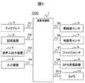
図1は、車載用ナビゲーション装置100の概略構成図である。図示するように、車載用ナビゲーション装置100は、演算処理部1と、ディスプレイ2と、記憶装置3と、音声入出力装置4と、入力装置5と、車輪速センサ6と、地磁気センサ7と、ジャイロセンサ8と、GPS(Global Positioning System)受信装置9と、カメラ10とを備えている。 FIG. 1 is a schematic configuration diagram of an in-
演算処理部1は、様々な処理を行う中心的ユニットである。例えば各種センサ6〜8やGPS受信装置9から出力される情報を基にして現在地を検出する。また、得られた現在地情報に基づいて、表示に必要な地図データを記憶装置3から読み出す。また、読み出した地図データをグラフィックス展開し、そこに現在地を示すマークを重ねてディスプレイ2へ表示する。また、記憶装置3に記憶されている地図データを用いて、ユーザから指示された目的地と現在地(出発地)とを結ぶ最適な経路(推奨経路)を探索する。また、音声入出力装置4やディスプレイ2を用いてユーザを誘導する。 The
ディスプレイ2は、演算処理部1で生成されたグラフィックス情報を表示するユニットである。ディスプレイ2は、CRTや液晶ディスプレイなどで構成される。演算処理部1とディスプレイ2との間の信号S1は、RGB信号やNTSC(National Television System Committee)信号で接続するのが一般的である。 The
記憶装置3は、CD-ROMやDVD-ROMやHDDやICカードといった記憶媒体で構成されている。この記憶媒体には、地図データが記憶されている。 The
地図データは、地図上の区画された領域であるメッシュの識別コード(メッシュID)ごとに、そのメッシュ領域に含まれる道路を構成する各リンクのリンクデータを含む。リンクデータは、リンクIDごとに、リンクを構成する2つのノード(開始ノード、終了ノード)の座標情報、リンクを含む道路の種別情報、リンクの長さを示すリンク長情報、リンク旅行時間、2つのノードにそれぞれ接続するリンクのリンクID(接続リンクID)などを含んでいる。 The map data includes, for each mesh identification code (mesh ID), which is a partitioned area on the map, link data of each link constituting a road included in the mesh area. The link data includes, for each link ID, coordinate information of two nodes (start node and end node) constituting the link, road type information including the link, link length information indicating the link length, link travel time, 2 It includes the link ID (connection link ID) of the link connected to each node.
また、地図データには、対応するメッシュ領域に含まれている道路以外の地図構成物(建物、街路樹、ガードレールなど)の情報(位置、大きさなど)も含まれている。 The map data also includes information (position, size, etc.) of map components (buildings, street trees, guardrails, etc.) other than roads included in the corresponding mesh area.
音声入出力装置4は、演算処理部1で生成したユーザへのメッセージを音声信号に変換し出力する。また、ユーザが発した声を認識し演算処理部1にその内容を転送する処理を行う。 The voice input /
入力装置5は、ユーザからの指示を受け付けるユニットである。入力装置5はディスプレイ2の前面に設置されたタッチパネルで構成される。ただし、入力装置5として、スクロールキー、縮尺変更キーなどのハードスイッチ、ジョイスティックなどを備えていてよい。 The
センサ6〜8およびGPS受信装置9は、車載用ナビゲーション装置100で現在地(自車位置)を検出するために使用されるものである。車輪速センサ6は、車輪の円周と計測される車輪の回転数の積から距離を測定し、さらに対となる車輪の回転数の差から移動体が曲がった角度を計測する。地磁気センサ7は、地球が保持している磁場を検知し、移動体が向いている方角を検出する。ジャイロ8は、光ファイバジャイロや振動ジャイロ等で構成され、移動体が回転した角度を検出するものである。GPS受信装置9は、GPS衛星からの信号を受信し移動体とGPS衛星間の距離と距離の変化率を3個以上の衛星に対して測定することで移動体の現在位置、進行速度および進行方位を測定する。 The
カメラ10は、車載用ナビゲーション装置100が搭載されている車両の周辺の映像を取得するための撮影装置である。カメラ10は、CCDカメラなどの小型カメラで構成される。 The
図2はカメラ10の設置の様子を示す側面図である。カメラ10は、例えば、車両88の上部に、支持台10sを介して取り付けられている。支持台10sは、カメラ10の撮影方位10xを、水平方向及び垂直方向(パン、チルト)に変位可能とする。支持台10sの制御は、ステッピングモータにより行われる。 FIG. 2 is a side view showing how the
図3はカメラ10の設置の様子を示す平面図である。カメラ10の車両88に対する設置位置は、予め定められている。また、GPS受信装置9のアンテナ91の車両に対する設置位置も予め定められている。GPSアンテナ91の設置位置及びカメラ10の設置位置に関する情報は予め登録されているので、車載用ナビゲーション装置100は、GPS受信装置9が出力する現在位置(GPSアンテナの位置)を基準に、カメラ10の地図上の座標位置を求めることができる。また、カメラ10の車両に対する設置方位θbは、支持台10sのステッピングモータの回転角により求めることができるので、車載用ナビゲーション装置100は、車両方位(図中、基準方位Nとして、θa)と、カメラ10の車両に対する設置方位θbとから、カメラ10の撮影方位10x(図中、基準方位Nとして、θ)を求めることができる。なお、カメラ10の座標位置を、GPS受信装置9の座標位置と近似して用いても良い。 FIG. 3 is a plan view showing how the
図4は、演算処理部1の機能ブロック図である。 FIG. 4 is a functional block diagram of the
図示するように、演算処理部1は、ユーザ操作解析部41と、経路探索部42と、経路誘導部43と、現在位置算出部44と、情報記憶部45、地点登録部46と、表示処理部47とを備えている。 As illustrated, the
ユーザ操作解析部41は、入力装置5に入力されたユーザからの要求を受け、その要求内容を解析して、その要求内容に対応する処理が実行されるように演算処理部1の各部を制御する。例えば、ユーザから地点登録の要求を受け付けたときは、地点登録に関する処理が行われるように地点登録部46に指示する。 The user
現在位置算出部44は、車輪速センサ6で計測される距離パルスデータS5およびジャイロ8で計測される角加速度データS7を各々積分した結果得られる距離データおよび角度データを用い、そのデータを時間軸で積分していくことにより、初期位置(X,Y)から自車走行後の位置である仮想現在地(X′,Y′)を定期的に演算する。また、仮想現在位置を、地図データを用いて、マップマッチ処理することにより、形状の相関が最も高い道路(リンク)上に、現在位置を合わせ込む。 The current
経路探索部42は、ダイクストラ法等を用いて、指定された2地点(現在地、目的地)間を結ぶ経路のコスト(例えば、旅行時間)が最少となる経路を探索する。 The
経路誘導部43は、経路探索部42で探索された経路を用いて経路誘導を行う。 The
情報記憶部45には、予めGPSアンテナの設置位置及びカメラ10の設置位置に関する情報が記憶されている。 The
地点登録部46は、ユーザの指示に従って任意の地点を情報記憶部45に登録する。また、ユーザからの指示に従って、カメラ10で撮像した映像内の建物等に関し地図上の座標位置を求め、その位置を登録する。 The
表示処理部47は、ディスプレイ2に表示すべき情報の描画コマンドを生成し、生成したコマンドを、ディスプレイ2に送信する。また、表示する地図の範囲内に登録された地点がある場合、登録地点があることを示す情報(例えば、旗マーク)が表示されるようにする。 The
図5は、演算処理部1のハードウェア構成例を示す図である。 FIG. 5 is a diagram illustrating a hardware configuration example of the
図示するように、演算処理部1は、各デバイス間をバス32で接続した構成としてある。演算処理部1は、数値演算及び各デバイスを制御するといった様々な処理を実行するCPU(Central Processing Unit)21と、記憶装置3から読み出した地図データ、演算データなどを格納するRAM(Random Access Memory)22と、プログラムやデータを格納するROM(Read Only Memory)23と、メモリ間およびメモリと各デバイスとの間のデータ転送を実行するDMA(Direct Memory Access)24と、グラフィックス描画を実行し且つ表示制御を行う描画コントローラ25と、グラフィックスイメージデータを蓄えるVRAM(Video Random Access Memory)26と、イメージデータをRGB信号に変換するカラーパレット27と、アナログ信号をデジタル信号に変換するA/D変換器28と、シリアル信号をバスに同期したパラレル信号に変換するSCI(Serial Communication Interface)29と、パラレル信号をバスに同期させてバス上にのせるPIO(Parallel Input/Output)30と、パルス信号を積分するカウンタ31と、カメラ10のステッピングモータに制御命令を送信して撮影方向を制御するとともに、撮像して得たアナログ信号を画像データに変換するカメラ制御装置33とを有する。 As illustrated, the
[動作の説明]次に、上記構成の車載用ナビゲーション装置100の動作について説明する。 [Description of Operation] Next, the operation of the in-
本実施形態の車載用ナビゲーション装置100は、地図上の任意の地点を登録する機能を備えている。かかる地点登録の機能は、車両の現在位置を登録するに限らず、カメラ10で撮像した画像内にある建物等の位置を登録することもできる。 The in-
図6は、かかる地点登録処理の流れを示すフロー図である。 FIG. 6 is a flowchart showing the flow of the point registration process.
ユーザ操作解析部41は、ユーザから入力装置5を介してカメラ10の撮影画像を表示するように要求されると、表示処理部47を介してカメラ10の撮影画像をディスプレイ2に表示する(S10)。 When the user
図7は、撮影画像510の表示例を示す。このように、撮影画像を表示している間、ユーザ操作解析部41は、ユーザから入力装置5を介して、撮影画像上の任意の位置を受け付ける。すなわち、撮影画像上の点の指定を受け付けたかどうか監視する(S11)。上述の通り、ディスプレイ2の前面には、入力装置5としてタッチパネルが配置されている。ユーザ操作解析部41は、ユーザによりタッチパネルがタッチされると、タッチされたパネル上の位置に対応する撮影画像上の位置を特定する。図7では、点Qが指定されたとする。 FIG. 7 shows a display example of the captured image 510. In this way, while displaying the captured image, the user
撮影画像上のいずれかの位置が指定された場合(S11でYes)、地点登録部46は、指定された点に対応する地図上の座標位置(緯度、経度)を求める(S12)。 When any position on the captured image is designated (Yes in S11), the
図8及び図9は、撮影画像上の指定された点の地図上の座標位置を求める方法を説明するための図である。図8(a)は側面図であり、図8(b)は撮影画像510を示す。また、図9(a)は天頂方向からの平面図であり、図9(b)は撮影画像510である。 8 and 9 are diagrams for explaining a method for obtaining a coordinate position on a map of a specified point on a captured image. FIG. 8A is a side view, and FIG. 8B shows a captured image 510. 9A is a plan view from the zenith direction, and FIG. 9B is a captured image 510. FIG.
図8(a)に示すように、カメラ10の撮影方位(H−P2)は、仰角θmとして、地面503に向けて少し傾いている。なお、地面503は、ほぼ水平であると推定する。カメラ10の視野502は、カメラ位置Hを中心に遠方ほど広がり、地面503上では、P1−P3の範囲となる。また、図9(a)に示すように、水平方向の視野502は、地面503上では、P4−P6の範囲となる。撮影画像510は、図8(b)及び図9(b)に示すように、撮影方位(H−P2)に垂直な投影面501における画像である。 As shown in FIG. 8A, the shooting direction (H-P2) of the
かかる場合、図8に示すように、撮影画像510の最も下に位置する点p1の地図上の座標位置は、点P1に相当する。また、撮影画像510の最も上に位置する点p3の座標位置は、点P3に相当する。一方、図9に示すように、撮影画像510の最も左に位置する点p4の座標位置は、点P4に相当する。また、撮影画像510の最も右に位置する点p6の座標位置は、点P6に相当する。 In such a case, as shown in FIG. 8, the coordinate position on the map of the point p1 located at the bottom of the captured image 510 corresponds to the point P1. Further, the coordinate position of the point p3 located at the top of the photographed image 510 corresponds to the point P3. On the other hand, as shown in FIG. 9, the coordinate position of the leftmost point p4 in the captured image 510 corresponds to the point P4. Further, the coordinate position of the point p6 located on the rightmost side of the captured image 510 corresponds to the point P6.
そして、撮影画像中の点Qの地図上の座標位置は、カメラ位置Hと投影面501上の点Qとを結ぶ線Lと、地面503との交点qとなる。したがって、カメラの地図上の座標位置、撮影方位が分かれば、撮影画像中の点の地図座標上の位置を求めることができる。 The coordinate position of the point Q in the captured image on the map is an intersection q between the line L connecting the camera position H and the point Q on the
カメラ10の車両88への設置位置は予め登録されているので、地点登録部46は、車両の現在位置と車両方位とカメラ10の設置位置から、カメラ10の地図上の座標位置を求めることができる。また、図3に示すように、カメラ10の撮影方位θは、車両方位θaと、カメラ10の支持台に向けられたステッピングモータの回転角から定められるカメラ10の設置方位θbとから求めることができる。そして、地点登録部46は、こうして求めたカメラ10の地図上の座標位置と、撮影方位θと、撮影画像中の指定された点の位置とから、指定された点の地図上の座標位置を求めることができる。 Since the installation position of the
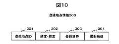
図6に戻って説明を続ける。次に、地点登録部46は、求められた点の位置を登録する。具体的には、地点登録部46は、図10に示すように、登録地点を識別するための情報(登録地点ID)301と、S12で求めた指定された点の座標位置(緯度、経度)302と、登録日時303と、撮影映像304を含む登録地点情報300を生成し、情報記憶部45に登録する。なお、登録する撮影映像304は、ディスプレイ2に表示した撮影画像510のうち、指定された点の周囲の画像を切り抜いたもの(例えば、指定された点から所定距離にある画像領域)を登録するようにしてもよい。 Returning to FIG. 6, the description will be continued. Next, the
その後、ユーザ操作解析部41は、S10に戻り、再び、撮影画像を表示し、地点登録要求の有無を監視する(S11)。 Thereafter, the user
この地点登録処理は、ユーザから入力装置5を介して撮影画像の表示の停止要求があった場合に、終了する。 This point registration process ends when the user requests to stop the display of the captured image via the
こうして、登録された地点は、様々な処理に利用される。例えば、経路探索の際の目的地設定の処理において、目的地の候補として登録された地点をリストアップして表示する。例えば、登録された日時が最近のものから順にリストアップして表示する。 Thus, the registered point is used for various processes. For example, in the destination setting process when searching for a route, points registered as destination candidates are listed and displayed. For example, the registered date and time are listed and displayed in order from the latest one.
また、図11に示すように、画面600に表示した地図601内に登録地点602がある場合、表示処理部47は、登録地点情報300の登録映像304を取得し、取得した映像603を表示するようにしてもよい。なお、撮影した映像が動画である場合は、動画を表示するようにしてもよい。 As shown in FIG. 11, when there is a registered
以上、本発明の一実施形態について説明した。 The embodiment of the present invention has been described above.
上記実施形態によれば、カメラで撮像した画像の中の任意の点の指定を受け付け、受け付けた点の地図上の座標位置を求めて、その位置を地点登録する。したがって、車両の現在位置そのものでなく、ユーザの視野にある建物等の位置を地点登録することができる。また、ユーザは、地点登録したい位置を、ディスプレイ上のタッチパネルで指定するだけでよいので、操作が簡便である。 According to the above-described embodiment, designation of an arbitrary point in the image captured by the camera is received, the coordinate position of the received point on the map is obtained, and the position is registered as a point. Therefore, it is possible to register the location of the building or the like in the user's field of view instead of the current location of the vehicle. Further, since the user only has to specify the position to be registered with the touch panel on the display, the operation is simple.
本発明は、上記実施形態に限定されない。上記実施形態は、本発明の要旨の範囲内で様々な変形が可能である。 The present invention is not limited to the above embodiment. The above embodiment can be variously modified within the scope of the gist of the present invention.
例えば、撮影画像中の指定された点の座標位置を求める方法は、上述した図8及び図9で示した方法に限定されない。具体的には、地点登録部46は、まず、撮影画像中の指定された点の位置に基づいて、カメラ位置からその点に対応する物体(例えば、建物)までの方位を求める。次に、カメラをその方位に合わせるとともに、焦点をその物体に合わせ、焦点距離を測り、カメラからその物体までの距離Dを求める。次に、カメラの地図上の座標位置と、カメラの方位と、求めた物体までの距離Dとから、その物体の地図上の座標位置を求める。また、距離センサを設けて、物体までの距離を求めるようにしてもよい。 For example, the method for obtaining the coordinate position of the designated point in the captured image is not limited to the method shown in FIGS. Specifically, the
また、ユーザにより画像中の建物などが指定された場合、その建物の最下部(建物と地上の接触地点)を、S11における指定された点として、地図上の座標位置を求めるようにしてもよい。こうすれば、地面上の地点を指定されなかった場合でも、より精度よく、ユーザが登録しようとする建物の地点を登録できる。例えば、ユーザが電柱を指して地点登録しようとした場合に、タッチパネルにて電柱の画像の中間を指定したとする。電柱などの建物は、同系色であるので、ユーザにより指定された点の色と同じ色であって、繋がりのある範囲を特定し、電柱を構成する画像領域を特定する。そして、地点登録部46は、特定した画像領域について、下方向に色の変化を調べていき、地面の色(例えば道路上では、黒)になった地点を、電柱の付け根とし、この地点を登録すべき地点とする。 Further, when a user designates a building or the like in the image, the coordinate position on the map may be obtained with the lowest part of the building (the contact point between the building and the ground) as the designated point in S11. . In this way, even if a point on the ground is not designated, the point of the building to be registered by the user can be registered with higher accuracy. For example, when the user points to a utility pole and tries to register a point, it is assumed that the middle of the utility pole image is designated on the touch panel. Since buildings such as utility poles have similar colors, a range that is the same color as the color of the point designated by the user and that is connected is specified, and an image area that constitutes the utility pole is specified. Then, the
また、車両へのカメラの設置位置は、上述した位置に限定されない。車両の側面に設置するものであってもよい。また、上記実施形態では、カメラは、回動する支持台により撮影方位を可変としたが、撮影方位が固定されるものであってもよい。 Moreover, the installation position of the camera in a vehicle is not limited to the position mentioned above. It may be installed on the side of the vehicle. In the above-described embodiment, the camera has a shooting direction variable by the rotating support base. However, the shooting direction may be fixed.
また、上記実施形態では、本発明を車載用ナビゲーション装置の地点登録に適用する場合について説明したが、地図情報を収集する測量装置に適用することもできる。例えば、新たな施設が建設され地図データを更新する必要がある場合、その施設の座標位置を知る必要がある。従来は、人が測量しその施設の座標位置を求めていた。本発明を測量装置に適用すれば、ユーザは、撮影画像中の測量したい施設を指定するだけで、その施設の座標位置を測量できる。 Moreover, although the said embodiment demonstrated the case where this invention was applied to the point registration of a vehicle-mounted navigation apparatus, it can also be applied to the surveying apparatus which collects map information. For example, when a new facility is constructed and map data needs to be updated, it is necessary to know the coordinate position of the facility. In the past, people surveyed to find the coordinate position of the facility. If the present invention is applied to a surveying device, the user can survey the coordinate position of the facility only by specifying the facility to be surveyed in the captured image.
かかる測量装置の構成は、経路探索部42や経路誘導部43を備えない点を除いて、基本的に上述した車載用ナビゲーション装置100と同様である。地点登録部46は、ユーザにタッチパネルなどの入力装置5を介して、撮影した画像中で、測量したい施設の位置を指定させる。そして、その位置の座標位置を求めて、情報記憶部45に登録する。または、ユーザからの要求に応じて、座標位置をディスプレイ2に出力する。こうすれば、撮像画像中の施設の位置を指定するだけで、座標位置を計算する測量装置が達成される。なお、カメラは、前方に向いている必要はなく、後方に向いていても良いし、ユーザからの要求に応じて、自由に撮影方位を変えられるようにしてもよい。 The configuration of the surveying device is basically the same as that of the vehicle-mounted
100…車載用ナビゲーション装置、
1…演算処理部、2…ディスプレイ、3…記憶装置、4…音声出入力装置、5…入力装置、6…車輪速センサ、7…地磁気センサ、8…ジャイロ、9…GPS受信機、10…カメラ
21…CPU、22…RAM、23…ROM、24…DMA、25…描画コントローラ、26…VRAM、27…カラーパレット、28…A/D変換器、29…SCI、30…PIO、31…カウンタ、33…カメラ制御装置、41…ユーザ操作解析部、42…経路探索部、43…経路誘導部、44…現在位置算出部、45…情報記憶部、46…地点登録部、47…表示処理部100: In-vehicle navigation device,
DESCRIPTION OF
Claims (5)
Translated fromJapanese地図データを記憶する記憶手段と、
撮影装置と、
前記撮影装置により撮影して得た映像を表示する表示手段と、
前記表示手段により表示された映像内の点の指定を受け付ける受付手段と、
前記受付手段により受け付けた点に対応する地図上の位置を求める登録地点算出手段と、
前記登録地点算出手段により求めた地図上の位置を登録する地点登録手段と
を備えることを特徴とするナビゲーション装置。A navigation device,
Storage means for storing map data;
A photographing device;
Display means for displaying an image obtained by photographing with the photographing device;
Accepting means for accepting designation of a point in the video displayed by the display means;
Registration point calculation means for obtaining a position on a map corresponding to the point received by the reception means;
A navigation apparatus comprising: a point registration unit that registers a position on a map obtained by the registration point calculation unit.
地図データを記憶する記憶手段と、
撮影装置と、
前記撮影装置により撮影して得た映像を表示する表示手段と、
前記表示手段により表示された映像内の点を受け付ける受付手段と、
前記撮影装置の地図上の位置及び撮影方位を取得する手段と、
前記受付手段により受け付けた点の前記映像内の位置と、前記撮影装置の地図上の位置と、撮影方位とを用いて、当該点に対応する地図上の位置を求める登録地点算出手段と、
前記登録地点算出手段により求めた地図上の位置を登録する地点登録手段と
を備えることを特徴とするナビゲーション装置。A navigation device,
Storage means for storing map data;
A photographing device;
Display means for displaying an image obtained by photographing with the photographing device;
Receiving means for receiving a point in the video displayed by the display means;
Means for acquiring a position on a map and a photographing direction of the photographing device;
A registered point calculating means for obtaining a position on the map corresponding to the point using the position in the video of the point received by the receiving means, the position on the map of the photographing device, and the photographing direction;
A navigation apparatus comprising: a point registration unit that registers a position on a map obtained by the registration point calculation unit.
前記ナビゲーション装置が搭載されている車両の現在位置と車両方位を取得する手段と、
前記撮影装置の前記車両への設置位置と設置方位を取得する手段と、
前記車両の現在位置と、前記撮影装置の前記車両への設置位置とから、前記撮影装置の地図上の位置を求める手段と、
前記車両方位と、前記撮影装置の車両への設置方位とから、前記撮影装置の撮影方位を求める手段と
を備えることを特徴とするナビゲーション装置。In claim 2,
Means for acquiring a current position and a vehicle direction of a vehicle on which the navigation device is mounted;
Means for acquiring an installation position and an installation orientation of the photographing apparatus on the vehicle;
Means for obtaining a position of the photographing apparatus on a map from a current position of the vehicle and an installation position of the photographing apparatus on the vehicle;
A navigation apparatus comprising: means for obtaining a shooting direction of the imaging apparatus from the vehicle direction and an installation direction of the imaging apparatus on the vehicle.
前記受付手段は、タッチパネルを備えている
ことを特徴とするナビゲーション装置。In claim 1 or 2,
The navigation device characterized in that the receiving means includes a touch panel.
前記地点登録手段は、前記登録地点算出手段により求めた地図上の位置を、前記撮影装置で撮影した映像とともに登録し、
前記ナビゲーション装置は、
登録された位置を含む地図を表示する場合、登録した映像を表示する
ことを特徴とするナビゲーション装置。In claim 1 or 2,
The location registration means registers the position on the map obtained by the registration location calculation means together with the video imaged by the imaging device,
The navigation device
A navigation apparatus characterized by displaying a registered video when displaying a map including a registered position.
Priority Applications (1)
| Application Number | Priority Date | Filing Date | Title |
|---|---|---|---|
| JP2005200719AJP4695933B2 (en) | 2005-07-08 | 2005-07-08 | Navigation device |
Applications Claiming Priority (1)
| Application Number | Priority Date | Filing Date | Title |
|---|---|---|---|
| JP2005200719AJP4695933B2 (en) | 2005-07-08 | 2005-07-08 | Navigation device |
Publications (2)
| Publication Number | Publication Date |
|---|---|
| JP2007017351Atrue JP2007017351A (en) | 2007-01-25 |
| JP4695933B2 JP4695933B2 (en) | 2011-06-08 |
Family
ID=37754633
Family Applications (1)
| Application Number | Title | Priority Date | Filing Date |
|---|---|---|---|
| JP2005200719AExpired - Fee RelatedJP4695933B2 (en) | 2005-07-08 | 2005-07-08 | Navigation device |
Country Status (1)
| Country | Link |
|---|---|
| JP (1) | JP4695933B2 (en) |
Cited By (4)
| Publication number | Priority date | Publication date | Assignee | Title |
|---|---|---|---|---|
| WO2009101679A1 (en)* | 2008-02-13 | 2009-08-20 | Pioneer Corporation | Picture display device, picture display method and picture display program |
| CN104159016A (en)* | 2013-05-13 | 2014-11-19 | 浙江大华技术股份有限公司 | Cradle head control system, method and device |
| JP2016122381A (en)* | 2014-12-25 | 2016-07-07 | 株式会社リコー | Optical flow calculation device, optical flow calculation method, and program |
| JP2016149132A (en)* | 2015-02-12 | 2016-08-18 | ホンダ リサーチ インスティテュート ヨーロッパ ゲーエムベーハーHonda Research Institute Europe GmbH | System and method for prediction in driver assist system of vehicle |
Citations (6)
| Publication number | Priority date | Publication date | Assignee | Title |
|---|---|---|---|---|
| JPH01263688A (en)* | 1988-04-15 | 1989-10-20 | Toshio Yamazaki | Map display device for navigation |
| JPH09210707A (en)* | 1996-02-02 | 1997-08-15 | Casio Comput Co Ltd | Navigation device |
| JPH1186027A (en)* | 1997-07-11 | 1999-03-30 | Werk Japan:Kk | Image display method |
| JPH11351888A (en)* | 1998-06-08 | 1999-12-24 | Mitsubishi Electric Corp | Navigation device |
| JP2003166843A (en)* | 2001-11-30 | 2003-06-13 | Fujitsu Ten Ltd | Navigation device |
| JP2004106682A (en)* | 2002-09-18 | 2004-04-08 | Honda Motor Co Ltd | Obstacle detection device |
- 2005
- 2005-07-08JPJP2005200719Apatent/JP4695933B2/ennot_activeExpired - Fee Related
Patent Citations (6)
| Publication number | Priority date | Publication date | Assignee | Title |
|---|---|---|---|---|
| JPH01263688A (en)* | 1988-04-15 | 1989-10-20 | Toshio Yamazaki | Map display device for navigation |
| JPH09210707A (en)* | 1996-02-02 | 1997-08-15 | Casio Comput Co Ltd | Navigation device |
| JPH1186027A (en)* | 1997-07-11 | 1999-03-30 | Werk Japan:Kk | Image display method |
| JPH11351888A (en)* | 1998-06-08 | 1999-12-24 | Mitsubishi Electric Corp | Navigation device |
| JP2003166843A (en)* | 2001-11-30 | 2003-06-13 | Fujitsu Ten Ltd | Navigation device |
| JP2004106682A (en)* | 2002-09-18 | 2004-04-08 | Honda Motor Co Ltd | Obstacle detection device |
Cited By (5)
| Publication number | Priority date | Publication date | Assignee | Title |
|---|---|---|---|---|
| WO2009101679A1 (en)* | 2008-02-13 | 2009-08-20 | Pioneer Corporation | Picture display device, picture display method and picture display program |
| CN104159016A (en)* | 2013-05-13 | 2014-11-19 | 浙江大华技术股份有限公司 | Cradle head control system, method and device |
| CN104159016B (en)* | 2013-05-13 | 2017-10-27 | 浙江大华技术股份有限公司 | Cloud platform control system, method and device |
| JP2016122381A (en)* | 2014-12-25 | 2016-07-07 | 株式会社リコー | Optical flow calculation device, optical flow calculation method, and program |
| JP2016149132A (en)* | 2015-02-12 | 2016-08-18 | ホンダ リサーチ インスティテュート ヨーロッパ ゲーエムベーハーHonda Research Institute Europe GmbH | System and method for prediction in driver assist system of vehicle |
Also Published As
| Publication number | Publication date |
|---|---|
| JP4695933B2 (en) | 2011-06-08 |
Similar Documents
| Publication | Publication Date | Title |
|---|---|---|
| US20230417567A1 (en) | Augmented reality maps | |
| JP6763448B2 (en) | Visually enhanced navigation | |
| JP6202535B2 (en) | Method for ensuring continuity of service of personal navigation device and device | |
| CN1755326B (en) | navigation device | |
| JP6025433B2 (en) | Portable navigation device | |
| JP6106495B2 (en) | Detection device, control method, program, and storage medium | |
| JP3798489B2 (en) | Car navigation system | |
| CN103453901A (en) | Position guiding system and position guiding method | |
| JP2002168647A (en) | Direction presentation method and mobile terminal | |
| JP2007071581A (en) | Navigation device | |
| JP4942411B2 (en) | Navigation device | |
| JP2003004463A (en) | Navigation system and program thereof | |
| JP5063871B2 (en) | Map display system for portable devices | |
| JP4695933B2 (en) | Navigation device | |
| CN102288180B (en) | Real-time image navigation system and method | |
| JP2011174748A (en) | Device, method and program for map display | |
| JP7429049B2 (en) | Pedestrian location system and pedestrian location software | |
| JP4776276B2 (en) | Navigation device | |
| RU2375756C2 (en) | Navigation device with information received from camera | |
| JP2014066595A (en) | Navigation apparatus | |
| JP2006064414A (en) | Display method for navigation system | |
| JP2007071539A (en) | On-vehicle navigation device | |
| JP2011149957A (en) | Image display device, image display method, and program | |
| JP7575337B2 (en) | Destination Guidance System | |
| JP2007010515A (en) | Navigation system |
Legal Events
| Date | Code | Title | Description |
|---|---|---|---|
| A621 | Written request for application examination | Free format text:JAPANESE INTERMEDIATE CODE: A621 Effective date:20080704 | |
| A711 | Notification of change in applicant | Free format text:JAPANESE INTERMEDIATE CODE: A712 Effective date:20100212 | |
| A977 | Report on retrieval | Free format text:JAPANESE INTERMEDIATE CODE: A971007 Effective date:20101208 | |
| TRDD | Decision of grant or rejection written | ||
| A01 | Written decision to grant a patent or to grant a registration (utility model) | Free format text:JAPANESE INTERMEDIATE CODE: A01 Effective date:20110222 | |
| A01 | Written decision to grant a patent or to grant a registration (utility model) | Free format text:JAPANESE INTERMEDIATE CODE: A01 | |
| A61 | First payment of annual fees (during grant procedure) | Free format text:JAPANESE INTERMEDIATE CODE: A61 Effective date:20110228 | |
| FPAY | Renewal fee payment (event date is renewal date of database) | Free format text:PAYMENT UNTIL: 20140304 Year of fee payment:3 | |
| R150 | Certificate of patent or registration of utility model | Free format text:JAPANESE INTERMEDIATE CODE: R150 | |
| R250 | Receipt of annual fees | Free format text:JAPANESE INTERMEDIATE CODE: R250 | |
| R250 | Receipt of annual fees | Free format text:JAPANESE INTERMEDIATE CODE: R250 | |
| R250 | Receipt of annual fees | Free format text:JAPANESE INTERMEDIATE CODE: R250 | |
| LAPS | Cancellation because of no payment of annual fees |