JP2007014936A - Method for producing microstructure and microreacter - Google Patents
Method for producing microstructure and microreacterDownload PDFInfo
- Publication number
- JP2007014936A JP2007014936AJP2005213881AJP2005213881AJP2007014936AJP 2007014936 AJP2007014936 AJP 2007014936AJP 2005213881 AJP2005213881 AJP 2005213881AJP 2005213881 AJP2005213881 AJP 2005213881AJP 2007014936 AJP2007014936 AJP 2007014936A
- Authority
- JP
- Japan
- Prior art keywords
- liquid
- flow path
- flow
- channel
- microreactor
- Prior art date
- Legal status (The legal status is an assumption and is not a legal conclusion. Google has not performed a legal analysis and makes no representation as to the accuracy of the status listed.)
- Pending
Links
- 238000004519manufacturing processMethods0.000titleclaimsabstractdescription31
- 239000007788liquidSubstances0.000claimsabstractdescription137
- 238000000034methodMethods0.000claimsabstractdescription24
- 239000000835fiberSubstances0.000claimsdescription33
- 239000010419fine particleSubstances0.000claimsdescription29
- UXVMQQNJUSDDNG-UHFFFAOYSA-LCalcium chlorideChemical compound[Cl-].[Cl-].[Ca+2]UXVMQQNJUSDDNG-UHFFFAOYSA-L0.000claimsdescription19
- BOTDANWDWHJENH-UHFFFAOYSA-NTetraethyl orthosilicateChemical compoundCCO[Si](OCC)(OCC)OCCBOTDANWDWHJENH-UHFFFAOYSA-N0.000claimsdescription17
- 239000007864aqueous solutionSubstances0.000claimsdescription16
- 239000011259mixed solutionSubstances0.000claimsdescription13
- 235000010443alginic acidNutrition0.000claimsdescription12
- 229920000615alginic acidPolymers0.000claimsdescription12
- 239000000126substanceSubstances0.000claimsdescription12
- 239000001110calcium chlorideSubstances0.000claimsdescription10
- 229910001628calcium chlorideInorganic materials0.000claimsdescription10
- 239000000783alginic acidSubstances0.000claimsdescription7
- 229960001126alginic acidDrugs0.000claimsdescription7
- 150000004781alginic acidsChemical class0.000claimsdescription7
- 239000003054catalystSubstances0.000claimsdescription4
- 239000000243solutionSubstances0.000description23
- 229910004298SiO 2Inorganic materials0.000description21
- 239000000648calcium alginateSubstances0.000description21
- 235000010410calcium alginateNutrition0.000description21
- 229960002681calcium alginateDrugs0.000description21
- OKHHGHGGPDJQHR-YMOPUZKJSA-Lcalcium;(2s,3s,4s,5s,6r)-6-[(2r,3s,4r,5s,6r)-2-carboxy-6-[(2r,3s,4r,5s,6r)-2-carboxylato-4,5,6-trihydroxyoxan-3-yl]oxy-4,5-dihydroxyoxan-3-yl]oxy-3,4,5-trihydroxyoxane-2-carboxylateChemical compound[Ca+2].O[C@@H]1[C@H](O)[C@H](O)O[C@@H](C([O-])=O)[C@H]1O[C@H]1[C@@H](O)[C@@H](O)[C@H](O[C@H]2[C@H]([C@@H](O)[C@H](O)[C@H](O2)C([O-])=O)O)[C@H](C(O)=O)O1OKHHGHGGPDJQHR-YMOPUZKJSA-L0.000description21
- 238000006243chemical reactionMethods0.000description11
- 239000012510hollow fiberSubstances0.000description11
- VHUUQVKOLVNVRT-UHFFFAOYSA-NAmmonium hydroxideChemical compound[NH4+].[OH-]VHUUQVKOLVNVRT-UHFFFAOYSA-N0.000description8
- 235000011114ammonium hydroxideNutrition0.000description8
- 239000011347resinSubstances0.000description8
- 229920005989resinPolymers0.000description8
- 230000015271coagulationEffects0.000description7
- 238000005345coagulationMethods0.000description7
- 238000006116polymerization reactionMethods0.000description7
- XLYOFNOQVPJJNP-UHFFFAOYSA-NwaterSubstancesOXLYOFNOQVPJJNP-UHFFFAOYSA-N0.000description7
- VEXZGXHMUGYJMC-UHFFFAOYSA-NHydrochloric acidChemical compoundClVEXZGXHMUGYJMC-UHFFFAOYSA-N0.000description6
- 230000003287optical effectEffects0.000description6
- 239000002245particleSubstances0.000description6
- FHVDTGUDJYJELY-UHFFFAOYSA-N6-{[2-carboxy-4,5-dihydroxy-6-(phosphanyloxy)oxan-3-yl]oxy}-4,5-dihydroxy-3-phosphanyloxane-2-carboxylic acidChemical compoundO1C(C(O)=O)C(P)C(O)C(O)C1OC1C(C(O)=O)OC(OP)C(O)C1OFHVDTGUDJYJELY-UHFFFAOYSA-N0.000description5
- 229940072056alginateDrugs0.000description5
- 229920001432poly(L-lactide)Polymers0.000description5
- IXPNQXFRVYWDDI-UHFFFAOYSA-N1-methyl-2,4-dioxo-1,3-diazinane-5-carboximidamideChemical compoundCN1CC(C(N)=N)C(=O)NC1=OIXPNQXFRVYWDDI-UHFFFAOYSA-N0.000description4
- LFQSCWFLJHTTHZ-UHFFFAOYSA-NEthanolChemical compoundCCOLFQSCWFLJHTTHZ-UHFFFAOYSA-N0.000description4
- 239000000661sodium alginateSubstances0.000description4
- 235000010413sodium alginateNutrition0.000description4
- 229940005550sodium alginateDrugs0.000description4
- 238000009987spinningMethods0.000description4
- HEMHJVSKTPXQMS-UHFFFAOYSA-MSodium hydroxideChemical compound[OH-].[Na+]HEMHJVSKTPXQMS-UHFFFAOYSA-M0.000description3
- 239000012295chemical reaction liquidSubstances0.000description3
- 238000011156evaluationMethods0.000description3
- 239000003595mistSubstances0.000description3
- 229920000642polymerPolymers0.000description3
- 238000011144upstream manufacturingMethods0.000description3
- 229920001410MicrofiberPolymers0.000description2
- -1NH 4 OHChemical compound0.000description2
- VYPSYNLAJGMNEJ-UHFFFAOYSA-NSilicium dioxideChemical compoundO=[Si]=OVYPSYNLAJGMNEJ-UHFFFAOYSA-N0.000description2
- FAPWRFPIFSIZLT-UHFFFAOYSA-MSodium chlorideChemical class[Na+].[Cl-]FAPWRFPIFSIZLT-UHFFFAOYSA-M0.000description2
- 238000000975co-precipitationMethods0.000description2
- 238000001723curingMethods0.000description2
- 238000002149energy-dispersive X-ray emission spectroscopyMethods0.000description2
- 238000005516engineering processMethods0.000description2
- 235000019441ethanolNutrition0.000description2
- 239000002657fibrous materialSubstances0.000description2
- 230000007062hydrolysisEffects0.000description2
- 238000006460hydrolysis reactionMethods0.000description2
- 238000005342ion exchangeMethods0.000description2
- 238000005304joiningMethods0.000description2
- 239000007791liquid phaseSubstances0.000description2
- 230000005381magnetic domainEffects0.000description2
- 239000000463materialSubstances0.000description2
- 239000012528membraneSubstances0.000description2
- 239000003658microfiberSubstances0.000description2
- 238000002156mixingMethods0.000description2
- 239000002105nanoparticleSubstances0.000description2
- 238000006068polycondensation reactionMethods0.000description2
- 239000002243precursorSubstances0.000description2
- 230000000541pulsatile effectEffects0.000description2
- 230000010349pulsationEffects0.000description2
- 238000003980solgel methodMethods0.000description2
- 238000005118spray pyrolysisMethods0.000description2
- RYHBNJHYFVUHQT-UHFFFAOYSA-N1,4-DioxaneChemical compoundC1COCCO1RYHBNJHYFVUHQT-UHFFFAOYSA-N0.000description1
- BHPQYMZQTOCNFJ-UHFFFAOYSA-NCalcium cationChemical compound[Ca+2]BHPQYMZQTOCNFJ-UHFFFAOYSA-N0.000description1
- 238000012695Interfacial polymerizationMethods0.000description1
- QGZKDVFQNNGYKY-UHFFFAOYSA-NammoniaNatural productsNQGZKDVFQNNGYKY-UHFFFAOYSA-N0.000description1
- 238000004458analytical methodMethods0.000description1
- 229910001424calcium ionInorganic materials0.000description1
- 230000000052comparative effectEffects0.000description1
- 238000006482condensation reactionMethods0.000description1
- 239000004020conductorSubstances0.000description1
- 230000018044dehydrationEffects0.000description1
- 238000006297dehydration reactionMethods0.000description1
- 238000009792diffusion processMethods0.000description1
- 238000009826distributionMethods0.000description1
- 108010025899gelatin filmProteins0.000description1
- 230000001788irregularEffects0.000description1
- 238000002074melt spinningMethods0.000description1
- 244000005700microbiomeSpecies0.000description1
- 239000003094microcapsuleSubstances0.000description1
- 239000011859microparticleSubstances0.000description1
- 239000000203mixtureSubstances0.000description1
- AHHWIHXENZJRFG-UHFFFAOYSA-NoxetaneChemical compoundC1COC1AHHWIHXENZJRFG-UHFFFAOYSA-N0.000description1
- 238000005192partitionMethods0.000description1
- 238000000016photochemical curingMethods0.000description1
- 239000000049pigmentSubstances0.000description1
- 238000012643polycondensation polymerizationMethods0.000description1
- 238000012805post-processingMethods0.000description1
- 239000000377silicon dioxideSubstances0.000description1
- 230000005476size effectEffects0.000description1
- 239000007787solidSubstances0.000description1
- 238000007711solidificationMethods0.000description1
- 230000008023solidificationEffects0.000description1
- 238000003756stirringMethods0.000description1
- 238000004381surface treatmentMethods0.000description1
- LFQCEHFDDXELDD-UHFFFAOYSA-Ntetramethyl orthosilicateChemical compoundCO[Si](OC)(OC)OCLFQCEHFDDXELDD-UHFFFAOYSA-N0.000description1
- 238000005406washingMethods0.000description1
- 238000002166wet spinningMethods0.000description1
Images


Landscapes
- Physical Or Chemical Processes And Apparatus (AREA)
- Catalysts (AREA)
Abstract
Description
Translated fromJapanese本発明は、微小構造体の製造方法およびマイクロリアクターに関する。より詳細には、本発明は、所望の形状を有し、かつサイズのバラツキが小さい微小構造体を、歩留まり良く、かつ、簡便安価に製造する方法、および、そのような微小構造体を容易に製造することが可能なマイクロリアクターに関する。 The present invention relates to a method for manufacturing a microstructure and a microreactor. More specifically, the present invention relates to a method for manufacturing a microstructure having a desired shape and small size variation with good yield and at a low cost, and to easily provide such a microstructure. The present invention relates to a microreactor that can be manufactured.
微小構造体(例えば、ナノメートルまたはマイクロメートルの径を有するファイバー)は、比表面積が非常に大きい。このような微小構造体は、固体でありながら気体または液体との界面が非常に大きくなる。その結果、微小構造体は、表面特性が全体の特性に与える影響の度合いが非常に大きい。また例えば、ナノメートルサイズの径を有するファイバーは、その径が光の波長よりも小さくなること、導体の平均自由工程よりも小さくなること、磁性体の磁区よりも小さくなること等に起因して、同じ物質のバルク状態とは全く異なる電子的、光学的、電気的、磁気的および機械的特性を発揮する(量子サイズ効果)(非特許文献1参照)。 Microstructures (eg, fibers having a nanometer or micrometer diameter) have a very large specific surface area. Such a microstructure has a very large interface with a gas or a liquid while being a solid. As a result, the microstructure has a very large degree of influence of the surface characteristics on the overall characteristics. Also, for example, a fiber having a nanometer-sized diameter is caused by the fact that the diameter is smaller than the wavelength of light, the mean free path of the conductor is smaller, the magnetic domain is smaller than the magnetic domain, etc. It exhibits electronic, optical, electrical, magnetic and mechanical properties that are completely different from the bulk state of the same substance (quantum size effect) (see Non-Patent Document 1).
従来、ファイバーの製造方法としては、溶融紡糸法、湿式紡糸法、界面重合法等が知られている。しかし、このような従来技術では、ナノメートルサイズの径を有するファイバーを安定的に製造することは実質的に不可能である。 Conventionally, melt spinning methods, wet spinning methods, interfacial polymerization methods, and the like are known as fiber manufacturing methods. However, with such conventional technology, it is practically impossible to stably manufacture a fiber having a nanometer size diameter.
特に、ナノメートルサイズ〜マイクロメートルサイズのファイバーを製造しようとする場合、非常に高価で大型の装置が必要となる。しかも、そのような装置を用いても、歩留まりが非常に悪い。加えて、得られるファイバーの径の分布が非常に大きく、また、所望の形状(例えば、楕円形、星形、中空のような断面形状)を有するファイバーを製造することは実質的に不可能である。 In particular, when manufacturing nanometer-sized to micrometer-sized fibers, a very expensive and large-sized apparatus is required. Moreover, the yield is very poor even when such an apparatus is used. In addition, the resulting fiber diameter distribution is very large, and it is virtually impossible to produce fibers having the desired shape (eg, elliptical, star, hollow cross-sectional shape). is there.
一方、微小構造体の別の代表例である微粒子を形成する方法として液相法が知られている。液相法としては、共沈法、ゾル−ゲル法、噴射熱分解法(液滴−粒子転換プロセス)等が知られている。共沈法、ゾル−ゲル法は、製造工程が煩雑であるという問題を有する。噴射熱分解法は、比較的装置が単純で、ワンステップでの製造が可能であるという点で注目を集めている。しかし、これらの方法はいずれも、非常に微小な(例えば、ナノサイズの)微粒子を形成することは実質的に困難である。
本発明は、上記従来の課題を解決するためになされたものであり、その目的とするところは、所望の形状を有し、かつサイズのバラツキが小さい微小構造体を、歩留まり良く、かつ、簡便安価に形成する方法を提供することにある。 The present invention has been made in order to solve the above-described conventional problems, and an object of the present invention is to provide a microstructure having a desired shape and small size variation with high yield and simple. The object is to provide a method of forming at low cost.
本発明の微小構造体の製造方法は、第1の流路に第1の液体を供給する工程と;該第1の流路を包囲するように形成された第2の流路に第2の液体を供給する工程と;該第1の流路と該第2の流路とが合流する地点で該第1の液体と該第2の液体とを接触させる工程とを含み、該第1の液体および該第2の液体を層流状態で接触させる。 The method for manufacturing a microstructure of the present invention includes a step of supplying a first liquid to a first flow path; a second flow path formed to surround the first flow path; Supplying a liquid; and contacting the first liquid and the second liquid at a point where the first flow path and the second flow path meet, The liquid and the second liquid are brought into contact in a laminar flow state.
好ましい実施形態においては、上記層流のレイノルズ数は0.1〜200である。 In preferable embodiment, the Reynolds number of the said laminar flow is 0.1-200.
好ましい実施形態においては、上記第1の液体の流量は、上記第2の液体の流量より小さい。 In a preferred embodiment, the flow rate of the first liquid is smaller than the flow rate of the second liquid.
好ましい実施形態においては、上記製造方法は、上記第1の液体および第2の液体を接触させた後、触媒に接触させる工程をさらに含む。 In a preferred embodiment, the manufacturing method further includes a step of contacting the catalyst after contacting the first liquid and the second liquid.
好ましい実施形態においては、上記製造方法は、上記第1の液体および第2の液体を接触させて、形状保持物質で形状保持された中間体を形成した後、微小構造体を形成し、該微小構造体から該形状保持物質を除去する工程をさらに含む。 In a preferred embodiment, in the manufacturing method, the first liquid and the second liquid are brought into contact with each other to form an intermediate body held in shape by a shape-holding substance, and then a microstructure is formed. The method further includes the step of removing the shape-retaining substance from the structure.
好ましい実施形態においては、上記第1の液体は連続的に供給される。別の実施形態においては、上記第1の液体は脈動的に供給される。 In a preferred embodiment, the first liquid is supplied continuously. In another embodiment, the first liquid is supplied in a pulsatile manner.
好ましい実施形態においては、上記第1の流路は、直径1〜1000μmの実質的に円形の断面形状を有する。別の実施形態においては、上記第1の流路は、楕円形、多角形、十字形または星形の断面形状を有する。 In a preferred embodiment, the first flow path has a substantially circular cross-sectional shape with a diameter of 1 to 1000 μm. In another embodiment, the first flow path has an elliptical, polygonal, cross-shaped or star-shaped cross-sectional shape.
好ましい実施形態においては、上記第1の液体はアルギン酸水溶液とテトラエトキシシランとの混合液であり、上記第2の液体は塩化カルシウム水溶液である。 In a preferred embodiment, the first liquid is a mixed solution of an alginate aqueous solution and tetraethoxysilane, and the second liquid is a calcium chloride aqueous solution.
好ましい実施形態においては、上記製造方法は、微粒子、ロッドまたはファイバーを形成する。 In a preferred embodiment, the production method forms microparticles, rods or fibers.
本発明の別の局面においては、マイクロリアクターが提供される。本発明のマイクロリアクターは、第1の液体が供給される第1の流路と、第2の液体が供給される第2の流路と、該第1の流路と該第2の流路が3次元的に合流して形成される合流流路を備え、該第1の流路における出口を端部とする少なくとも一部が該第2の流路に包囲されてなる。 In another aspect of the invention, a microreactor is provided. The microreactor of the present invention includes a first flow path to which a first liquid is supplied, a second flow path to which a second liquid is supplied, the first flow path, and the second flow path. Includes a merge channel formed by three-dimensionally merging, and at least a part of the first channel having an outlet as an end is surrounded by the second channel.
好ましい実施形態においては、本発明のマイクロリアクターは、上記第2の流路への第2の液体の供給口を複数個備える。 In a preferred embodiment, the microreactor of the present invention includes a plurality of second liquid supply ports to the second flow path.
好ましい実施形態においては、本発明のマイクロリアクターは、上記第1の流路の出口の内径が0.05〜0.8mmである。 In a preferred embodiment, in the microreactor of the present invention, the inner diameter of the outlet of the first flow path is 0.05 to 0.8 mm.
好ましい実施形態においては、本発明のマイクロリアクターは、上記第2の流路における、上記第1の流路の出口を含む断面の内径が、(上記第1の流路の出口の内径+0.2)mm以上、(上記第1の流路の出口の内径+1.6)mm以下である。 In a preferred embodiment, the microreactor of the present invention has an inner diameter of a cross section including the outlet of the first channel in the second channel (the inner diameter of the outlet of the first channel +0.2). ) Mm or more and (inner diameter of the outlet of the first flow path +1.6) mm or less.
好ましい実施形態においては、本発明のマイクロリアクターは、上記第1の流路に、上記第1の液体を脈動的に流すためのパルス発生手段が備えられている。 In a preferred embodiment, the microreactor of the present invention is provided with pulse generating means for causing the first liquid to flow in a pulsating manner in the first flow path.
好ましい実施形態においては、上記パルス発生手段は、上記第1の流路の一部をダイアフラム部として該ダイアフラム部をアクチュエーターで振動させる。 In a preferred embodiment, the pulse generating means vibrates the diaphragm portion with an actuator using a part of the first flow path as a diaphragm portion.
好ましい実施形態においては、本発明のマイクロリアクターは、上記第1の流路中における第1の液体の流量と上記第2の流路中における第2の液体の流量を可変するための流量制御手段を備える。 In a preferred embodiment, the microreactor of the present invention includes a flow rate control means for varying the flow rate of the first liquid in the first flow channel and the flow rate of the second liquid in the second flow channel. Is provided.
本発明によれば、マイクロリアクターを用いて反応液を層流状態で接触させることにより、以下のような利点が得られる:(1)液−液界面での反応となるので、材料選択の自由度が大きく、かつ、安全である;(2)微小空間において非常に安定で精密な反応が実現されるので、得られる微小構造体の均一性にきわめて優れる;(3)流路および反応液の供給形態を変えることにより、所望の形状の微小構造体を形成することが可能である;(4)流量を制御するだけで得られる微小構造体のサイズを変えることが可能である;および(5)歩留まり良く、低コストで効率良く微小構造体を製造することが可能である。本発明で得られる微小構造体としては、例えば、ナノ・マイクロサイズのマイクロファイバー、マイクロ構造体(繊維(ファイバー)、中空繊維、粒子、異形粒子、マイクロロット、各種形状マイクロカプセルなど)などが挙げられる。 According to the present invention, the following advantages can be obtained by contacting the reaction liquid in a laminar flow state using a microreactor: (1) Since the reaction is performed at the liquid-liquid interface, the material can be freely selected. (2) Extremely stable and precise reaction is realized in a minute space, so that the uniformity of the resulting microstructure is extremely excellent; (3) Flow path and reaction solution By changing the supply form, it is possible to form a microstructure with a desired shape; (4) it is possible to change the size of the microstructure obtained by simply controlling the flow rate; and (5 ) It is possible to manufacture a microstructure with good yield and low cost efficiently. Examples of the microstructure obtained in the present invention include nano / micro-sized microfibers, microstructures (fibers, hollow fibers, particles, irregularly shaped particles, microlots, various-shaped microcapsules, etc.). It is done.
以下、本発明の好ましい実施形態について説明するが、本発明はこれらの実施形態には限定されない。なお、本発明において、流路の「内径」とは、流路方向から見た断面形状が実質的に円形の場合にはその内部の直径を、流路方向から見た断面形状が円形以外の場合には内部の径に対応する長さを意味するものとする。例えば、断面形状が実質的に正方形の場合には、その内部の対角線の長さを意味するものとする。 Hereinafter, although preferable embodiment of this invention is described, this invention is not limited to these embodiment. In the present invention, the “inner diameter” of the flow path means the internal diameter when the cross-sectional shape viewed from the flow path direction is substantially circular, and the cross-sectional shape viewed from the flow path direction is other than circular. In this case, the length corresponding to the inner diameter is meant. For example, when the cross-sectional shape is substantially square, it means the length of the diagonal inside.
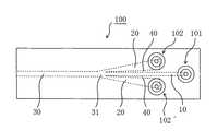
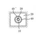
図1(a)は、本発明の好ましい実施形態による製造方法に好ましく用いることができる装置(マイクロリアクター)100の流路方向に沿った概略断面図であり、図1(b)は、そのB−B線による(すなわち、流路方向から見た)断面図である。図2は装置100を上方から見た概略図であり、図3は装置100の斜視図である。この装置100は、第1の流路10と、第1の流路を包囲するように設けられた第2の流路20と、第1の流路10および第2の流路20が合流して形成される合流流路30とを有する。第1の流路10と第2の流路20とは、合流点(すなわち、合流流路の上流端部)31の上流側(図示例では右側)においては、隔壁40によって仕切られている。装置100は、第1の流路10への供給口101、第2の流路20への供給口102、102´を備える。供給口101、102、102´の形状および位置は、目的に応じて適宜設計され得る。例えば、図1〜3に示すように、供給口101、102、102´が全て上方に位置する場合であってもよいし、図4(装置100を上方から見た概略図)に示すように、供給口101、102、102´が全て側面に位置する場合であってもよい。それぞれの流路10、20および30の形状は、目的に応じて適宜設計され得る。例えば、図1〜3に示すような実施形態においては、第1の流路10の流路方向に沿った断面は実質的に直線状であり、第2の流路20の流路方向に沿った断面はテーパー状であり、合流流路30の流路方向に沿った断面は実質的に直線状である。別の実施形態においては、第1の流路10の流路方向に沿った断面は実質的にテーパー状であり、かつ、第2の流路のテーパーよりも小さいテーパーであり得る。また、例えば、図4に示すように、供給口101から第1の流路10へ向かう流路や、供給口102(102´)から第2の流路20へ向かう流路が、流路方向に沿って障害となる突起部や角部などを有さない形状であることも、気泡等の混入を避ける点で好ましい形態の1つである。 FIG. 1A is a schematic cross-sectional view of a device (microreactor) 100 that can be preferably used in the manufacturing method according to a preferred embodiment of the present invention along the flow path direction, and FIG. It is sectional drawing by the -B line (namely, seeing from the flow path direction). FIG. 2 is a schematic view of the
1つの実施形態においては、この装置の流路の全長Lは、約30mm〜約60mmである。1つの実施形態においては、第1の流路の径(流路方向から見た断面形状が実質的に円形の場合)または径に対応するサイズ(流路方向から見た断面形状が異形の場合)は、1μm〜1000μmである。 In one embodiment, the overall length L of the flow path of the device is from about 30 mm to about 60 mm. In one embodiment, the diameter of the first flow path (when the cross-sectional shape viewed from the flow path direction is substantially circular) or the size corresponding to the diameter (the cross-sectional shape viewed from the flow path direction is irregular) ) Is 1 μm to 1000 μm.
本発明のマイクロリアクターは、好ましい実施形態として、図1〜4の装置100に示すように、第1の液体が供給される第1の流路10と、第2の液体が供給される第2の流路20と、該第1の流路と該第2の流路が3次元的に合流して形成される合流流路30を備え、該第1の流路10における出口を端部とする少なくとも一部が該第2の流路20に包囲されてなる。 As a preferred embodiment, the microreactor of the present invention has a
本発明のマイクロリアクターは、図1〜4の装置100に示すように、第2の流路20への第2の液体の供給口を複数個備える(図1〜4においては102と102´)ことが好ましい。より好ましくは2〜5個、さらに好ましくは2〜3個である。このような構造とすることで、第2の流路20中における気泡の発生等を防止することが可能となるとともに、十分な層流を実現することが可能となる。 The microreactor of the present invention includes a plurality of second liquid supply ports to the
本発明のマイクロリアクターは、第1の流路10の出口の内径が0.05〜0.8mmであることが好ましく、より好ましくは0.1〜0.8mm、さらに好ましくは0.2〜0.7mm、特に好ましくは0.2〜0.6mm、最も好ましくは0.3〜0.5mmである。第1の流路10の出口の内径が上記範囲にあることによって、第1の液体と第2の液体とが、層流状態で3次元的に合流でき、所望の微小構造体を得ることが可能となる。 In the microreactor of the present invention, the inner diameter of the outlet of the
本発明のマイクロリアクターは、第2の流路における、第1の流路の出口を含む断面の内径が、(第1の流路の出口の内径+0.2)mm以上、(第1の流路の出口の内径+1.6)mm以下である、ことが好ましく、より好ましくは、(第1の流路の出口の内径+0.2)mm以上、(第1の流路の出口の内径+1.3)mm以下、さらに好ましくは、(第1の流路の出口の内径+0.3)mm以上、(前記第1の流路の出口の内径+1.0)mm以下である。第2の流路における、第1の流路の出口を含む断面の内径が上記範囲にあることによって、第1の液体と第2の液体とが、層流状態で3次元的に合流でき、所望の微小構造体を得ることが可能となる。 In the microreactor of the present invention, the inner diameter of the cross section including the outlet of the first channel in the second channel is (the inner diameter of the outlet of the first channel + 0.2) mm or more (first flow It is preferable that the inner diameter of the outlet of the passage +1.6) mm or less, more preferably, (the inner diameter of the outlet of the first flow path +0.2) mm or more, (the inner diameter of the outlet of the first flow path +1) .3) mm or less, more preferably, (the inner diameter of the outlet of the first flow path +0.3) mm or more and (the inner diameter of the outlet of the first flow path +1.0) mm or less. When the inner diameter of the cross section including the outlet of the first channel in the second channel is in the above range, the first liquid and the second liquid can be three-dimensionally merged in a laminar flow state, A desired microstructure can be obtained.
本発明のマイクロリアクターは、例えば、図5に示すように、第1の流路10に、第1の液体を脈動的に流すためのパルス発生手段50が備えられていてもよい。パルス発生手段50の位置は、第1の流路10の途中であればどこでもよく、目的に応じて適宜設計され得る。パルス状の圧力をかけるタイミングと時間とを制御することにより、得られる微小構造体の長さや形を任意に調整することが可能になる。パルスの長さが短い場合には、微小構造体の長さが短くなり、ロットや微粒子などのマイクロ構造体の製造が可能となる。より好ましい実施形態においては、パルス発生手段50は、第1の流路10の一部をダイアフラム部として該ダイアフラム部をアクチュエーターで振動させる。例えば、図6に示すように、第1の流路10の一部に形成したダイアフラム部60をアクチュエーター70で振動させる。振動数は、好ましくは1〜30Hzである。アクチュエーター70としては、例えば、株式会社タウザー研究所製のリニアアクチュエーター(PMNA−1005S)が挙げられる。ダイアフラム部の薄肉部厚みは、好ましくは0.05〜0.50mm、より好ましくは0.07〜0.40mm、さらに好ましくは0.10〜0.30mmである。後述する光造形法によれば、図6に示すような構造のマイクロリアクターを容易に作製することができる。 In the microreactor of the present invention, for example, as shown in FIG. 5, pulse generation means 50 for causing the first liquid to flow in a pulsating manner may be provided in the
本発明のマイクロリアクターは、第1の流路10中における第1の液体の流量と第2の流路20中における第2の液体の流量を可変するための流量制御手段を備えていてもよい。流量制御手段は、好ましくは、出口側よりも供給口側に近いところ(上流側)に備える。流量制御手段としては、例えば、シリンジポンプ、ギアポンプなどが挙げられ、好ましくはシリンジポンプである。流量制御手段を備えることにより、第1の流路10中における第1の液体の流量と第2の流路20中における第2の液体の流量を可変できるため、得られる微小構造体の径を任意に制御することができ、また、微小構造体の種類によっては、硬化具合、硬化肉厚、中空断面などを任意に制御することができる。 The microreactor of the present invention may include a flow rate control means for varying the flow rate of the first liquid in the
本発明のマイクロリアクターは、どのような方法で作製しても良いが、容易且つ正確に作製できる等の点で、光造形法により作製することが好ましい。光造形法とは、3次元CADデータで設計された立体像を2次元のスライスデータに変換し、このデータに基づいて、レーザーで一層ずつ光硬化性樹脂を硬化させていき、3次元に積層造形していく方法である。より具体的には、3次元CADデータで設計された立体像を、幾層もの薄い断面体にスライスして2次元のスライスデータに変換し、この2次元のスライスデータに基づいてレーザーがタンク内の光硬化性樹脂の表面を走査して断面形状を描いていく。レーザーが当たった部分は硬化し、エレベーター上に一層分の断面体が形成される。その後、エレベーターが一層分ずつ下降して、連続的に幾層もの薄い断面体を積層し、3次元に積層造形していく。最後にエレベーターを引き上げることで、3次元に積層造形されたモデルを取り出し、後処理を施して完成させる。光造形法に用いることができる光造形装置としては、例えば、株式会社ディーメック製の光造形装置(例えば、SCS−1000HDなど)が挙げられる。光造形法に用いることができる光硬化性樹脂としては、例えば、株式会社ディーメック製の光硬化性樹脂(例えば、オキセタン系のSCR950など)が挙げられる。レーザーとしては、例えば、He−Cdレーザー(ピーク波長=325nm)が挙げられる。レーザーのスポットサイズは、例えば、φ10〜100μmが好ましく、φ30〜70μmがより好ましい。硬化させて得られる樹脂一層分の厚みは、例えば、10〜50μmが好ましく、20〜40μmがより好ましい。 The microreactor of the present invention may be produced by any method, but it is preferably produced by an optical modeling method in that it can be produced easily and accurately. The stereolithography method converts a 3D image designed with 3D CAD data into 2D slice data, and based on this data, the photocurable resin is cured layer by layer with a laser and laminated in 3D. It is a method of modeling. More specifically, a three-dimensional image designed with three-dimensional CAD data is sliced into thin layers of several layers and converted into two-dimensional slice data. Based on this two-dimensional slice data, the laser is inside the tank. The cross-sectional shape is drawn by scanning the surface of the photocurable resin. The portion irradiated with the laser is cured, and a cross-section for one layer is formed on the elevator. After that, the elevator descends one layer at a time, and several thin cross-sectional bodies are continuously laminated and three-dimensionally layered. Finally, by lifting the elevator, a three-dimensional layered model is taken out and subjected to post-processing to be completed. As an optical modeling apparatus that can be used for the optical modeling method, for example, an optical modeling apparatus (for example, SCS-1000HD) manufactured by Deemec Co., Ltd. may be used. Examples of the photocurable resin that can be used in the optical modeling method include a photocurable resin (for example, oxetane-based SCR950, etc.) manufactured by Deemec Co., Ltd. Examples of the laser include a He—Cd laser (peak wavelength = 325 nm). For example, the laser spot size is preferably φ10 to 100 μm, and more preferably φ30 to 70 μm. The thickness of one resin layer obtained by curing is preferably, for example, 10 to 50 μm, and more preferably 20 to 40 μm.
本発明の好ましい実施形態による製造方法は、上記第1の流路10に第1の液体を供給する工程と;上記第2の流路20に第2の液体を供給する工程と;該第1の流路と該第2の流路の合流点31で該第1の液体と該第2の液体とを接触させる工程とを含む。本発明においては、上記のような装置を用いることにより、第1の液体および第2の液体はその合流点31および合流流路30で層流を形成する。すなわち、本発明においては、第1の液体および第2の液体は、層流状態で接触する。第1の液体および第2の液体は、目的に応じて適宜選択され得る(第1の液体および第2の液体の代表例の詳細については後述する)。第1の液体および第2の液体を層流状態で接触させることにより、液−液界面での非常に安定な反応が可能となる。その結果、例えば第1の液体を連続的に供給する場合には、非常に安定な直線状の反応固化が実現され、非常に微小な径を有し、かつ径のばらつきがきわめて小さいファイバーが安定的に形成され得る。 The manufacturing method according to a preferred embodiment of the present invention includes a step of supplying a first liquid to the
本発明においては、第1の液体および第2の液体を層流状態で接触させるので、層流の界面における物質の移動・拡散を利用でき、界面において、「溶解から凝固」、「イオン交換」、「重縮合」などの化学反応を起こすことが可能となる。また、本発明においては第1の流路と該第2の流路を3次元的に合流させることで第1の液体および第2の液体を層流状態で接触させるので、比界面積が特に大きい3次元液−液界面を安定的に生成することができ、界面に沿った断面形状を有する微小構造体を流路進行方向に安定的に生成させることができる。 In the present invention, since the first liquid and the second liquid are contacted in a laminar flow state, the movement / diffusion of the substance at the interface of the laminar flow can be used. It is possible to cause chemical reactions such as “polycondensation”. In the present invention, the first liquid and the second liquid are brought into contact in a laminar flow state by three-dimensionally joining the first flow path and the second flow path, so that the specific interface area is particularly high. A large three-dimensional liquid-liquid interface can be stably generated, and a microstructure having a cross-sectional shape along the interface can be stably generated in the flow path traveling direction.
上記層流のレイノルズ数は好ましくは0.1〜200であり、さらに好ましくは0.5〜50であり、特に好ましくは1〜20であり、最も好ましくは1〜8である。このような非常に小さいレイノルズ数であれば、第1の液体と第2の液体の流量比を調整することにより、第1の液体の合流後の液幅を制御することができる。その結果、所望のサイズを有する微小構造体を非常に正確に得ることができる。このような非常に小さいレイノルズ数を有する層流状態における液−液反応を実現したことが本発明の大きな成果の1つである。また、レイノルズ数を上記範囲に制御することにより、マイクロリアクター内の第1の液体または第2の液体の流速を上昇させても、層流状態に乱れが生じ難く、3次元液−液界面に沿った断面形状を有する微小構造体を流路進行方向に安定的に生成させることができる。 The Reynolds number of the laminar flow is preferably 0.1 to 200, more preferably 0.5 to 50, particularly preferably 1 to 20, and most preferably 1 to 8. With such a very small Reynolds number, it is possible to control the liquid width after the first liquid merges by adjusting the flow ratio of the first liquid and the second liquid. As a result, a microstructure having a desired size can be obtained very accurately. One of the great achievements of the present invention is to realize a liquid-liquid reaction in a laminar flow state having such a very small Reynolds number. In addition, by controlling the Reynolds number within the above range, even if the flow velocity of the first liquid or the second liquid in the microreactor is increased, the laminar flow state is hardly disturbed, and the three-dimensional liquid-liquid interface is not generated. It is possible to stably generate a microstructure having a cross-sectional shape along the flow path traveling direction.
好ましくは、上記第1の液体の流量は、上記第2の液体の流量より小さい。第1の液体の流量を第2の液体の流量よりも小さくすることにより、微小構造体の非常に安定した形成が可能となる。例えばファイバーを形成する場合には、非常に小さい径を有し、かつ、径のばらつきがないファイバーを得ることができる。さらに、第2の液体の流量を大きくすることにより、合流流路30における生成微小構造体に起因する摩擦や閉塞を防止することができる。具体的には、第1の液体の流量は、好ましくは0.05〜1μl/秒であり、第2の液体の流量は、好ましくは0.2〜40μl/秒である。第1の液体と第2の液体の流量比は、好ましくは1:50〜1:400である。 Preferably, the flow rate of the first liquid is smaller than the flow rate of the second liquid. By making the flow rate of the first liquid smaller than the flow rate of the second liquid, it is possible to form the microstructure very stably. For example, when a fiber is formed, a fiber having a very small diameter and no variation in diameter can be obtained. Furthermore, by increasing the flow rate of the second liquid, it is possible to prevent friction and blockage caused by the generated microstructure in the
本発明においては、上記第1の液体が供給される流路(図1の第1の流路10)の形状および上記第1の液体の供給方法を変化させることにより、任意の適切な形状およびサイズの微小構造体を得ることができる。1つの実施形態においては、上記第1の流路10は、直径1〜1000μmの実質的に円形の断面形状を有する。別の実施形態においては、上記第1の流路10は、楕円形、多角形、十字形または星形の断面形状を有する。さらに別の実施形態においては、上記第1の流路10は、多層構造(例えば、上層と下層の2層構造、上層と中間層と下層の3層構造)や多重構造(例えば、図7の断面図に示すような内側流路と外側流路との2重構造、内側流路と中間流路と外側流路との3重構造)を有していてもよい。1つの実施形態においては、上記第1の液体は連続的に(すなわち、実質的に整流で)供給される。別の実施形態においては、上記第1の液体は脈動的に供給される。例えば、第1の流路10として実質的に円形の断面形状を有する流路を用い、上記第1の液体を連続的に供給すると、図8(a)に示すようなファイバーが得られる。また例えば、第1の流路10として四角形の断面形状を有する流路を用い、上記第1の液体を連続的に供給すると、図8(b)に示すようなファイバーが得られる。第1の流路形状を平坦な形状とすることにより、非常に薄い平坦なファイバーが得られる(図示せず)。例えば、第1の流路10として実質的に円形の断面形状を有する流路を用い、上記第1の液体を脈動的に供給すると、図8(c)に示すような微粒子が得られる。第1の液体の流路形状を変化させることにより、図8(d)に示すような微粒子が得られる。脈動のパルス形状を変化させることにより、図8(e)に示すようなロッドやいわゆる串団子状の微小構造体が得られる。また、反応液(第1の液体および第2の液体)の種類を適切に選択することにより、第1の液体を連続的に供給する場合であっても、微粒子が得られ得る。 In the present invention, by changing the shape of the flow path to which the first liquid is supplied (the
本発明においては、反応液(第1の液体および第2の液体)の種類を適切に選択し、および/または、第1の液体および第2の液体の流速を適切に選択し(リアクター内での接触時間を適切に選択)、および/または、適切な化学処理や表面処理を行うことにより、中空の微小構造体や多孔質の微小構造体を得ることができる。 In the present invention, the type of the reaction liquid (first liquid and second liquid) is appropriately selected, and / or the flow rates of the first liquid and second liquid are appropriately selected (within the reactor). The contact time is appropriately selected) and / or by performing an appropriate chemical treatment or surface treatment, a hollow microstructure or a porous microstructure can be obtained.
本発明における第1の液体と第2の液体の組み合わせ例(いずれが第1の液体でいずれが第2の液体かは問わない)としては、例えば、ポリ−L−乳酸溶液とイオン交換水、テトラエトキシシラン透明重合溶液とアンモニア水、などが挙げられる。 Examples of the combination of the first liquid and the second liquid in the present invention (which is the first liquid and which is the second liquid) include, for example, a poly-L-lactic acid solution and ion-exchanged water, Examples include tetraethoxysilane transparent polymerization solution and aqueous ammonia.
本発明においては、第1の液体中に予め他の物質を含有させておくことにより、得られる微小構造体中に他の物質を封入してなるマイクロ構造体を得ることができる。第1の液体と他の物質との組み合わせとしては、例えば、アルギン酸水溶液と顔料、アルギン酸水溶液と微生物、などが挙げられる。 In the present invention, by incorporating another substance in the first liquid in advance, a microstructure formed by enclosing another substance in the obtained microstructure can be obtained. Examples of the combination of the first liquid and another substance include an alginic acid aqueous solution and a pigment, an alginic acid aqueous solution and a microorganism, and the like.
本発明の製造方法の一例として、上記第1の液体としてアルギン酸水溶液(実用的には、アルギン酸ナトリウム水溶液)とテトラエトキシシランとの混合液を用い、上記第2の液体として塩化カルシウム水溶液を用いる場合について説明する。第1の流路10に上記混合液を連続的に供給し、第2の流路20に塩化カルシウム水溶液を連続的に供給する。合流点31で上記混合液と塩化カルシウム水溶液が接触すると、アルギン酸が塩化カルシウムのカルシウムイオンによって部分的にイオン架橋される。その結果、水に不溶性の(ゼリー状の)アルギン酸カルシウムが形成される。ここで、上記のように、混合液(アルギン酸)と塩化カルシウム水溶液は層流状態で接触するので、アルギン酸と塩化カルシウム水溶液とは実質的に混合されることなく、液−液界面でのみ反応する。その結果、上記混合液と塩化カルシウム水溶液との界面にアルギン酸カルシウムのゲル状膜が形成される。言い換えれば、ゲル状膜で構成された中空ファイバー状の外郭とその内部に含有された液体状のテトラエトキシシランとを有する、いわゆる芯鞘構造のファイバー状中間体が形成される。このアルギン酸カルシウムのゲル状膜が、形成される微小構造体の形状保持機能を有する。また、ゲル状膜内部のテトラエトキシシランは、SiO2の前駆体として機能する。なお、このような形状保持物質(ここでは、アルギン酸カルシウム)による中間体自体が、微小構造体であり得る。As an example of the production method of the present invention, a mixed liquid of an alginate aqueous solution (practically a sodium alginate aqueous solution) and tetraethoxysilane is used as the first liquid, and a calcium chloride aqueous solution is used as the second liquid. Will be described. The mixed liquid is continuously supplied to the
好ましくは、上記ファイバー状中間体を触媒(例えば、NaOH、NH4OH、塩酸)に接触させる。その結果、下記のような加水分解と脱水縮合反応が起こり、テトラエトキシシランからSiO2が生成する。上記アルギン酸カルシウムのゲル状膜を形成する場合には、得られるSiO2は微粒子となる。より具体的には、SiO2微粒子がアルギン酸カルシウムのゲル状中空ファイバーに内包された状態で得られる。一方、テトラエトキシシランと触媒を直接接触させることにより、非常に小さい径を有し、かつ、径のばらつきがないSiO2ファイバーが得られ得る。
Si(C2H5O)4 + 4H2O → Si(OH)4 + 4C2H5OH
Si(OH)4 → SiO2 + H2OPreferably, the fibrous intermediate is contacted with a catalyst (eg, NaOH, NH4 OH, hydrochloric acid). As a result, the following hydrolysis and dehydration condensation reactions occur, and SiO2 is generated from tetraethoxysilane. In the case of forming the calcium alginate gel-like film, the obtained SiO2 becomes fine particles. More specifically, it is obtained in a state where SiO2 fine particles are encapsulated in a gel-like hollow fiber of calcium alginate. On the other hand, by directly contacting the tetraethoxysilane and the catalyst, a SiO2 fiber having a very small diameter and no variation in diameter can be obtained.
Si (C2 H5 O)4 + 4H2 O → Si (OH)4 + 4C2 H5 OH
Si (OH)4 → SiO2 + H2 O
必要に応じて、得られたSiO2ファイバーからアルギン酸カルシウムのゲル状膜を除去する。アルギン酸カルシウムのゲル状膜の除去は、例えば飽和食塩水で洗浄することにより行われる。また、アルギン酸ナトリウム水溶液の濃度を変化させることにより、アルギン酸ナトリウム水溶液とテトラエトキシシランとの混合比率を変化させることにより、あるいは、アルギン酸カルシウムの除去の際に任意の適切な処理を行うことにより、所望の表面特性を有する微粒子(例えば、表面が平滑な微粒子、表面に凹凸構造を有する微粒子、または多孔質の微粒子)を得ることができる。If necessary, the gel-like film of calcium alginate is removed from the obtained SiO2 fiber. The removal of the calcium alginate gel-like film is performed, for example, by washing with saturated saline. Also, by changing the concentration of the aqueous sodium alginate solution, changing the mixing ratio of the aqueous sodium alginate solution and tetraethoxysilane, or by performing any appropriate treatment upon removal of calcium alginate, (For example, fine particles having a smooth surface, fine particles having an uneven structure on the surface, or porous fine particles) having the above surface characteristics.
以上のようにして、SiO2微粒子が得られる。アルギン酸水溶液とテトラエトキシシランとの混合液の供給形態や流路形状を変更することにより、SiO2の異形微粒子やロッドが得られることはいうまでもない。As described above, SiO2 fine particles are obtained. It goes without saying that the modified fine particles and rods of SiO2 can be obtained by changing the supply mode of the mixed solution of the alginic acid aqueous solution and tetraethoxysilane and the channel shape.
以下、実施例に基づいて本発明をより詳細に説明するが、本発明はこれらの実施例に限定されるものではない。 EXAMPLES Hereinafter, although this invention is demonstrated in detail based on an Example, this invention is not limited to these Examples.
図1〜3に示すマイクロリアクターについて、光造形装置(株式会社ディーメック製、商品名:SCS−1000HD)を用い、3次元CADデータで設計された立体像を、幾層もの薄い断面体にスライスして2次元のスライスデータに変換した。タンク内に光硬化性樹脂(株式会社ディーメック製、商品名:SCR950)とエレベーターを入れ、この2次元のスライスデータに基づいてレーザー(He−Cdレーザー、ピーク波長=325nm)をタンク内の光硬化性樹脂の表面に走査させ、断面形状を描いていった。レーザーのスポットサイズはφ50μmであった。レーザーが当たった部分は硬化し、エレベーター上に一層分の断面体(樹脂一層分の厚み=30μm)が形成された。その後、エレベーターが一層分ずつ下降して、連続的に幾層もの薄い断面体を積層し、3次元に積層造形していった。最後にエレベーターを引き上げることで、3次元に積層造形されたモデルを取り出し、後処理を施して、図1〜3に示すマイクロリアクターを完成させた。 For the microreactor shown in FIGS. 1 to 3, a three-dimensional image designed with three-dimensional CAD data is sliced into several thin cross-sections using a stereolithography apparatus (trade name: SCS-1000HD, manufactured by DEMEC). And converted into two-dimensional slice data. A photo-curing resin (trade name: SCR950, manufactured by DEMEC Co., Ltd.) and an elevator are placed in the tank, and a laser (He-Cd laser, peak wavelength = 325 nm) is applied to the light in the tank based on the two-dimensional slice data. The surface of the curable resin was scanned to draw a cross-sectional shape. The laser spot size was φ50 μm. The portion irradiated with the laser was cured, and a cross section for one layer (thickness for one resin layer = 30 μm) was formed on the elevator. After that, the elevator descended one layer at a time, and several thin cross-sections were continuously laminated and three-dimensionally layered. Finally, by lifting the elevator, a three-dimensional layered model was taken out and post-processed to complete the microreactor shown in FIGS.
3.5重量%アルギン酸ナトリウム水溶液10mlとテトラエトキシシラン(純度95%)2mlをビーカー中でスタラーを用いて十分に攪拌し、混合液を調製した。一方、塩化カルシウム粒子0.5gを水99.5gに溶解し、0.5重量%の塩化カルシウム溶液を調製した。実施例1で作製したマイクロリアクターを用い、第1の流路(内側流路)に上記混合液を流し、第2の流路(外側流路)に上記塩化カルシウム溶液を流した。混合液および塩化カルシウム溶液のいずれも、シリンジポンプを用いて連続的に流した。混合液の流量は0.45μl/秒であり、塩化カルシウム溶液の流量は29.1μl/秒であり、流量比は1:64であった。リアクターの合流点で混合液と塩化カルシウム水溶液とを接触させることにより、テトラメトキシシラン(SiO2前駆体)をアルギン酸カルシウムで内包したファイバー状中間体を得た。このファイバー状中間体を28重量%アンモニア水中に72時間沈水して、SiO2微粒子をアルギン酸カルシウムで内包したファイバーを得た。このファイバーを飽和食塩水に沈水し、アルギン酸カルシウムを除去した。次いで、メンブレンフィルターを用いてSiO2微粒子を回収した。得られた微粒子を2日間乾燥した。A mixed solution was prepared by sufficiently stirring 10 ml of a 3.5 wt% aqueous sodium alginate solution and 2 ml of tetraethoxysilane (purity 95%) using a stirrer in a beaker. On the other hand, 0.5 g of calcium chloride particles were dissolved in 99.5 g of water to prepare a 0.5 wt% calcium chloride solution. Using the microreactor produced in Example 1, the mixed solution was allowed to flow through the first flow path (inner flow path), and the calcium chloride solution was flowed into the second flow path (outer flow path). Both the mixed solution and the calcium chloride solution were continuously flowed using a syringe pump. The flow rate of the mixed solution was 0.45 μl / second, the flow rate of the calcium chloride solution was 29.1 μl / second, and the flow rate ratio was 1:64. By contacting the mixed solution and the aqueous calcium chloride solution at the junction of the reactor, a fibrous intermediate encapsulating tetramethoxysilane (SiO2 precursor) with calcium alginate was obtained. This fibrous intermediate was submerged in 28 wt% ammonia water for 72 hours to obtain a fiber in which SiO2 fine particles were encapsulated with calcium alginate. The fiber was submerged in saturated saline to remove calcium alginate. It was then recovered SiO2 particles with a membrane filter. The obtained fine particles were dried for 2 days.
上記SiO2微粒子を内包したアルギン酸カルシウムのファイバーをエネルギー分散型蛍光X線分析装置(EDX)で分析した。その結果、ファイバーの材質がアルギン酸カルシウムであることが確認された。また、ファイバーを破壊してファイバー内部を分析した結果、SiO2微粒子が形成されていると推定された。さらに、アルギン酸カルシウムのファイバーおよびSiO2微粒子を走査型電子顕微鏡(SEM)で観察した。その結果、ファイバーの断面は実質的に円形で、外径は約81μm、厚みは約10μmであった。微粒子のサイズは直径200nm以下と推定された。The calcium alginate fibers encapsulating the SiO2 fine particles were analyzed with an energy dispersive X-ray fluorescence analyzer (EDX). As a result, it was confirmed that the fiber material was calcium alginate. Furthermore, analysis of the internal fibers to destroy fiber was estimated to SiO2 particles are formed. Further, calcium alginate fibers and SiO2 fine particles were observed with a scanning electron microscope (SEM). As a result, the cross section of the fiber was substantially circular, the outer diameter was about 81 μm, and the thickness was about 10 μm. The size of the fine particles was estimated to be 200 nm or less in diameter.
混合液の流量を0.08μl/秒、塩化カルシウム溶液の流量を29.1μl/秒、したがって流量比を1:365としたこと以外は実施例2と同様にして、SiO2微粒子をアルギン酸カルシウムで内包したファイバーおよびSiO2微粒子を得た。得られたファイバーおよび微粒子について、実施例2と同様の評価に供した。その結果、ファイバーの材質がアルギン酸カルシウムであることが確認された。また、ファイバー内部にはSiO2微粒子が形成されていると推定された。ファイバーの断面は実質的に円形で、外径は約25μm、厚みは約5μmであった。微粒子のサイズは直径200nm以下と推定された。In the same manner as in Example 2 except that the flow rate of the mixed solution was 0.08 μl / second, the flow rate of the calcium chloride solution was 29.1 μl / second, and thus the flow rate ratio was 1: 365, the SiO2 fine particles were made of calcium alginate. Encapsulated fibers and SiO2 fine particles were obtained. The obtained fibers and fine particles were subjected to the same evaluation as in Example 2. As a result, it was confirmed that the fiber material was calcium alginate. It was also estimated that SiO2 fine particles were formed inside the fiber. The cross section of the fiber was substantially circular, the outer diameter was about 25 μm, and the thickness was about 5 μm. The size of the fine particles was estimated to be 200 nm or less in diameter.
混合液を脈動的に流したこと以外は実施例2と同様にして、SiO2微粒子をアルギン酸カルシウムで内包したロッドおよびSiO2微粒子を得た。混合液の脈動的な供給は、オンオフバルブ(Lee Company社製の超小型プランジャーバルブINKX0514300A)により行った。バルブの駆動条件は24Vであり、脈動のパルスは10pps(パルス/秒)であった。得られたロッドおよび微粒子について、実施例2と同様の評価に供した。その結果、ロッドの材質がアルギン酸カルシウムであることが確認された。また、ロッド内部にはSiO2微粒子が形成されていると推定された。ロッドの断面は楕円形で、径((長辺+短辺)/2)は約72μmであった。ロッドの長さは約1.1mmであった。微粒子のサイズは直径200nm以下と推定された。Except that the mixed solution was pulsated, rods and SiO2 fine particles enclosing SiO2 fine particles with calcium alginate were obtained in the same manner as in Example 2. The pulsating supply of the liquid mixture was performed by an on-off valve (a micro plunger valve INKX0514300A manufactured by Lee Company). The driving condition of the valve was 24 V, and the pulse of pulsation was 10 pps (pulse / second). The obtained rod and fine particles were subjected to the same evaluation as in Example 2. As a result, it was confirmed that the material of the rod was calcium alginate. It was also estimated that SiO2 fine particles were formed inside the rod. The rod had an oval cross section and a diameter ((long side + short side) / 2) of about 72 μm. The length of the rod was about 1.1 mm. The size of the fine particles was estimated to be 200 nm or less in diameter.
実施例1で作製したマイクロリアクターを用い、第1の流路(内側流路)に0.5重量%アルギン酸水溶液を流し、第2の流路(外側流路)に3.5重量%塩化カルシウム水溶液を流した。アルギン酸水溶液および塩化カルシウム水溶液のいずれも、シリンジポンプを用いて連続的に流した。アルギン酸水溶液の流量は27.8nl/秒であり、塩化カルシウム水溶液の流量は5.55μl/秒であり、直径50μmのアルギン酸カルシウムファイバーを得た。このときの製造速度は、マイクロファイバー10mm当たり0.71秒であった。
〔比較例1〕Using the microreactor produced in Example 1, a 0.5 wt% aqueous alginate solution was passed through the first flow path (inner flow path), and 3.5 wt% calcium chloride was passed through the second flow path (outer flow path). An aqueous solution was poured. Both the alginate aqueous solution and the calcium chloride aqueous solution were continuously flowed using a syringe pump. The flow rate of the aqueous alginate solution was 27.8 nl / second, the flow rate of the aqueous calcium chloride solution was 5.55 μl / second, and a calcium alginate fiber having a diameter of 50 μm was obtained. The production speed at this time was 0.71 second per 10 mm of microfiber.
[Comparative Example 1]
湿式二重紡糸機を用い、直径100μm以下のアルギン酸カルシウムファイバーからなる極細中空繊維の紡糸を行った。低い溶液濃度による粘度低下や、ノズルと凝固浴面との距離であるギャップ部分の延長による自重延伸などを試みても、極細中空繊維が得られなかった。 An ultrafine hollow fiber made of calcium alginate fiber having a diameter of 100 μm or less was spun using a wet double spinning machine. Even when attempts were made to reduce the viscosity due to a low solution concentration, or to perform self-weight stretching by extending the gap portion, which is the distance between the nozzle and the coagulation bath surface, ultrafine hollow fibers could not be obtained.
ポリ−L−乳酸15重量部をジオキサン85重量部に溶解させ、15重量%のポリ−L−乳酸溶液を作って被凝固ポリマー溶液として用いた。凝固液として、イオン交換水を用いた。両方の溶液をともに長時間室温に放置し、25℃の室温になったことを確かめて使用した。実施例1で作製したマイクロリアクターを用い、ポリ−L−乳酸溶液を鞘部(第2の流路)に、イオン交換水を芯部(第1の流路)に、シリンジポンプによって同じ速度でゆっくりと送り込んだ。顕微鏡により、層流状態でマイクロリアクター(合流流路)の内部を流れることを確かめ、凝固反応をマイクロリアクター(合流流路)の中で行い、紡糸した。ノズルから出た中空繊維に水ミストを付着させ、自重延伸させながら、中空繊維外面のさらなる凝固をさせ、直径20μmの極細多孔質ポリ−L−乳酸中空繊維を得た。 15 parts by weight of poly-L-lactic acid was dissolved in 85 parts by weight of dioxane to prepare a 15% by weight poly-L-lactic acid solution, which was used as a solidified polymer solution. Ion exchange water was used as the coagulation liquid. Both solutions were allowed to stand at room temperature for a long time and used after confirming that the room temperature was 25 ° C. Using the microreactor produced in Example 1, the poly-L-lactic acid solution was placed in the sheath (second flow path), the ion exchange water was placed in the core (first flow path), and the syringe pump at the same speed. Sent slowly. Using a microscope, the inside of the microreactor (merging channel) was confirmed to flow in a laminar flow state, and the coagulation reaction was performed in the microreactor (merging channel) and spinning was performed. Water mist was attached to the hollow fiber coming out of the nozzle, and the outer surface of the hollow fiber was further solidified while being stretched by its own weight to obtain an ultrafine porous poly-L-lactic acid hollow fiber having a diameter of 20 μm.
液状テトラエトキシシラン170重量部、水290重量部、エチルアルコール40重量部、1N塩酸1滴を加えて、12時間室温で液状テトラエトキシシランの加水分解と縮重合反応を起こさせ、均一な透明重合溶液を得た。この均一なテトラエトキシシラン透明重合溶液を被凝固ポリマー溶液として用いた。凝固液として、0.1Nアンモニア水を用いた。両方の溶液をともに長時間室温に放置し、25℃の室温になったことを確かめて使用した。実施例1で作製したマイクロリアクターを用い、均一なテトラエトキシシラン透明重合溶液を鞘部(第2の流路)に、0.1Nアンモニア水を芯部(第1の流路)に、ギアポンプによって同じ速度でゆっくりと送り込んだ。顕微鏡により、層流状態でマイクロリアクター(合流流路)の内部を流れることを確かめ、凝固反応をマイクロリアクター(合流流路)の中で行い、紡糸した。ノズルから出た中空繊維に0.1Nアンモニア水ミストを付着させ、自重延伸させながら、中空繊維外面のさらなる凝固をさせ、直径15μmの極細多孔質シリカ繊維を得た。 Uniform transparent polymerization by adding 170 parts by weight of liquid tetraethoxysilane, 290 parts by weight of water, 40 parts by weight of ethyl alcohol, and 1 drop of 1N hydrochloric acid to cause hydrolysis and condensation polymerization of liquid tetraethoxysilane at room temperature for 12 hours. A solution was obtained. This uniform tetraethoxysilane transparent polymerization solution was used as a polymer solution to be coagulated. As the coagulation liquid, 0.1N ammonia water was used. Both solutions were allowed to stand at room temperature for a long time and used after confirming that the room temperature was 25 ° C. Using the microreactor produced in Example 1, a uniform tetraethoxysilane transparent polymerization solution was applied to the sheath (second flow path), and 0.1N ammonia water was applied to the core (first flow path) by a gear pump. Sent slowly at the same speed. Using a microscope, the inside of the microreactor (merging channel) was confirmed to flow in a laminar flow state, and the coagulation reaction was performed in the microreactor (merging channel) and spinning was performed. A 0.1N ammonia water mist was attached to the hollow fiber coming out of the nozzle, and the outer surface of the hollow fiber was further solidified while being stretched by its own weight to obtain an ultrafine porous silica fiber having a diameter of 15 μm.
液状テトラエトキシシラン170重量部、水290重量部、エチルアルコール40重量部、1N塩酸1滴を加えて、12時間室温で液状テトラエトキシシランの加水分解と縮重合反応を起こさせた後、ポリアクリルアミド10重量部を加え、均一な有機無機ハイブリッド透明重合溶液を得た。この均一な有機無機ハイブリッド透明重合溶液を被凝固ポリマー溶液として用いた。凝固液として、0.1Nアンモニア水を用いた。両方の溶液をともに長時間室温に放置し、25℃の室温になったことを確かめて使用した。実施例1で作製したマイクロリアクターを用い、均一な有機無機ハイブリッド透明重合溶液を鞘部(第2の流路)に、0.1Nアンモニア水を芯部(第1の流路)に、ギアポンプによって同じ速度でゆっくりと送り込んだ。顕微鏡により、層流状態でマイクロリアクター(合流流路)の内部を流れることを確かめ、凝固反応をマイクロリアクター(合流流路)の中で行い、紡糸した。ノズルから出た中空繊維に0.1Nアンモニア水ミストを付着させ、自重延伸させながら、中空繊維外面のさらなる凝固をさせ、直径10μmの極細多孔質有機無機ハイブリッド繊維を得た。 After adding 170 parts by weight of liquid tetraethoxysilane, 290 parts by weight of water, 40 parts by weight of ethyl alcohol and 1 drop of 1N hydrochloric acid, the liquid tetraethoxysilane was hydrolyzed and subjected to a polycondensation reaction at room temperature for 12 hours. 10 parts by weight was added to obtain a uniform organic-inorganic hybrid transparent polymerization solution. This uniform organic-inorganic hybrid transparent polymerization solution was used as a polymer solution to be coagulated. As the coagulation liquid, 0.1N ammonia water was used. Both solutions were allowed to stand at room temperature for a long time and used after confirming that the room temperature was 25 ° C. Using the microreactor produced in Example 1, a uniform organic-inorganic hybrid transparent polymerization solution was used for the sheath (second flow path), 0.1N ammonia water was used for the core (first flow path), and a gear pump was used. Sent slowly at the same speed. Using a microscope, the inside of the microreactor (merging channel) was confirmed to flow in a laminar flow state, and the coagulation reaction was performed in the microreactor (merging channel) and spinning was performed. A 0.1N ammonia water mist was attached to the hollow fiber coming out of the nozzle, and the outer surface of the hollow fiber was further solidified while being stretched by its own weight to obtain an ultrafine porous organic-inorganic hybrid fiber having a diameter of 10 μm.
本発明の製造方法は、非常に安全であり、かつ、高精度であるので、各種の化学産業に広範囲に利用され得る。 Since the production method of the present invention is very safe and highly accurate, it can be widely used in various chemical industries.
100 マイクロリアクター
10 第1の流路
20 第2の流路
30 合流流路
31 合流点
40 隔壁
40´ 隔壁
50 パルス発生手段
60 ダイアフラム
70 アクチュエーター
101 第1の流路への供給口
102 第2の流路への供給口
102´ 第2の流路への供給口
DESCRIPTION OF
Claims (18)
Translated fromJapanese該第1の流路を包囲するように形成された第2の流路に第2の液体を供給する工程と;
該第1の流路と該第2の流路とが合流する地点で該第1の液体と該第2の液体とを接触させる工程とを含み、
該第1の液体および該第2の液体を層流状態で接触させる、微小構造体の製造方法。Supplying a first liquid to the first flow path;
Supplying a second liquid to a second channel formed to surround the first channel;
Contacting the first liquid and the second liquid at a point where the first flow path and the second flow path meet,
A method for manufacturing a microstructure, wherein the first liquid and the second liquid are contacted in a laminar flow state.
The flow rate control means for changing the flow volume of the 1st liquid in the said 1st flow path and the flow volume of the 2nd liquid in the said 2nd flow path is provided in any one of Claim 12-17 The described microreactor.
Priority Applications (1)
| Application Number | Priority Date | Filing Date | Title |
|---|---|---|---|
| JP2005213881AJP2007014936A (en) | 2005-01-07 | 2005-07-25 | Method for producing microstructure and microreacter |
Applications Claiming Priority (3)
| Application Number | Priority Date | Filing Date | Title |
|---|---|---|---|
| JP2005003056 | 2005-01-07 | ||
| JP2005169287 | 2005-06-09 | ||
| JP2005213881AJP2007014936A (en) | 2005-01-07 | 2005-07-25 | Method for producing microstructure and microreacter |
Publications (1)
| Publication Number | Publication Date |
|---|---|
| JP2007014936Atrue JP2007014936A (en) | 2007-01-25 |
Family
ID=37752540
Family Applications (1)
| Application Number | Title | Priority Date | Filing Date |
|---|---|---|---|
| JP2005213881APendingJP2007014936A (en) | 2005-01-07 | 2005-07-25 | Method for producing microstructure and microreacter |
Country Status (1)
| Country | Link |
|---|---|
| JP (1) | JP2007014936A (en) |
Cited By (7)
| Publication number | Priority date | Publication date | Assignee | Title |
|---|---|---|---|---|
| JP2007090306A (en)* | 2005-09-30 | 2007-04-12 | Kri Inc | Method for manufacturing microstructure and microreactor |
| JP2009018251A (en)* | 2007-07-11 | 2009-01-29 | Reika Kogyo Kk | Homogenizing apparatus |
| JP2009106864A (en)* | 2007-10-30 | 2009-05-21 | Fuji Xerox Co Ltd | Reaction method using micro-reactor and micro-reactor |
| JP2009242570A (en)* | 2008-03-31 | 2009-10-22 | Fujifilm Corp | Method and apparatus for producing fine particles |
| JP2017029981A (en)* | 2010-09-08 | 2017-02-09 | ジョンソン、マッセイ、パブリック、リミテッド、カンパニーJohnson Matthey Public Limited Company | Catalyst manufacturing method |
| JP2017189729A (en)* | 2016-04-12 | 2017-10-19 | 株式会社日立製作所 | Microreactor, chemical product production system and method for producing microreactor |
| JP2018040097A (en)* | 2016-08-31 | 2018-03-15 | 花王株式会社 | Method for producing hydrogel fiber |
Citations (6)
| Publication number | Priority date | Publication date | Assignee | Title |
|---|---|---|---|---|
| JPH01294545A (en)* | 1988-05-20 | 1989-11-28 | Nippon Telegr & Teleph Corp <Ntt> | Method for forming glass |
| JP2004124133A (en)* | 2002-09-30 | 2004-04-22 | Fuji Photo Film Co Ltd | Production method of metal particle |
| WO2004091763A2 (en)* | 2003-04-10 | 2004-10-28 | President And Fellows Of Harvard College | Formation and control of fluidic species |
| JP2006096569A (en)* | 2004-09-28 | 2006-04-13 | Fuji Photo Film Co Ltd | Method for producing copper oxide fine particle |
| JP2006193651A (en)* | 2005-01-14 | 2006-07-27 | Fuji Photo Film Co Ltd | Organic pigment fine particle and method for producing the same |
| JP2006272196A (en)* | 2005-03-29 | 2006-10-12 | Toshiba Corp | Composite type fine particle manufacturing method and composite type fine particle manufacturing apparatus |
- 2005
- 2005-07-25JPJP2005213881Apatent/JP2007014936A/enactivePending
Patent Citations (6)
| Publication number | Priority date | Publication date | Assignee | Title |
|---|---|---|---|---|
| JPH01294545A (en)* | 1988-05-20 | 1989-11-28 | Nippon Telegr & Teleph Corp <Ntt> | Method for forming glass |
| JP2004124133A (en)* | 2002-09-30 | 2004-04-22 | Fuji Photo Film Co Ltd | Production method of metal particle |
| WO2004091763A2 (en)* | 2003-04-10 | 2004-10-28 | President And Fellows Of Harvard College | Formation and control of fluidic species |
| JP2006096569A (en)* | 2004-09-28 | 2006-04-13 | Fuji Photo Film Co Ltd | Method for producing copper oxide fine particle |
| JP2006193651A (en)* | 2005-01-14 | 2006-07-27 | Fuji Photo Film Co Ltd | Organic pigment fine particle and method for producing the same |
| JP2006272196A (en)* | 2005-03-29 | 2006-10-12 | Toshiba Corp | Composite type fine particle manufacturing method and composite type fine particle manufacturing apparatus |
Cited By (9)
| Publication number | Priority date | Publication date | Assignee | Title |
|---|---|---|---|---|
| JP2007090306A (en)* | 2005-09-30 | 2007-04-12 | Kri Inc | Method for manufacturing microstructure and microreactor |
| JP2009018251A (en)* | 2007-07-11 | 2009-01-29 | Reika Kogyo Kk | Homogenizing apparatus |
| JP2009106864A (en)* | 2007-10-30 | 2009-05-21 | Fuji Xerox Co Ltd | Reaction method using micro-reactor and micro-reactor |
| JP2009242570A (en)* | 2008-03-31 | 2009-10-22 | Fujifilm Corp | Method and apparatus for producing fine particles |
| JP2017029981A (en)* | 2010-09-08 | 2017-02-09 | ジョンソン、マッセイ、パブリック、リミテッド、カンパニーJohnson Matthey Public Limited Company | Catalyst manufacturing method |
| JP2017189729A (en)* | 2016-04-12 | 2017-10-19 | 株式会社日立製作所 | Microreactor, chemical product production system and method for producing microreactor |
| WO2017179353A1 (en)* | 2016-04-12 | 2017-10-19 | 株式会社日立製作所 | Microreactor, formed product manufacturing system, and microreactor manufacturing method |
| US10464039B2 (en) | 2016-04-12 | 2019-11-05 | Hitachi, Ltd. | Microreactor, chemical product manufacturing system and microreactor manufacturing method |
| JP2018040097A (en)* | 2016-08-31 | 2018-03-15 | 花王株式会社 | Method for producing hydrogel fiber |
Similar Documents
| Publication | Publication Date | Title |
|---|---|---|
| Geng et al. | Multiphase microfluidics: fundamentals, fabrication, and functions | |
| Brugarolas et al. | Directed assembly of particles using microfluidic droplets and bubbles | |
| Gross et al. | Recent advances in analytical chemistry by 3D printing | |
| Lin et al. | Self‐propelled micro‐/nanomotors based on controlled assembled architectures | |
| Ku et al. | Soft patchy particles of block copolymers from interface-engineered emulsions | |
| Hood et al. | Synthetic strategies in the preparation of polymer/inorganic hybrid nanoparticles | |
| Ma et al. | Streamlined mesoporous silica nanoparticles with tunable curvature from interfacial dynamic-migration strategy for nanomotors | |
| Sebastian et al. | Reaction engineering strategies for the production of inorganic nanomaterials | |
| Wu et al. | Multiplex coaxial flow focusing for producing multicompartment Janus microcapsules with tunable material compositions and structural characteristics | |
| US9586371B2 (en) | Method of bonding material layers in an additive manufacturing process | |
| Ravichandran et al. | Intrinsic field-induced nanoparticle assembly in three-dimensional (3D) printing polymeric composites | |
| Nurumbetov et al. | A simple microfluidic device for fabrication of double emulsion droplets and polymer microcapsules | |
| CN102530853A (en) | Preparation method of artificial nanometer pipes and application of utilizing artificial nanometer pipes as nanometer motors | |
| CN103407290A (en) | Three-dimensional structure preparation method and device based on electronic jet printing | |
| CN106925360B (en) | Fabrication method of microfluidic chip based on nanofiber template method | |
| JP2007014936A (en) | Method for producing microstructure and microreacter | |
| US20110215277A1 (en) | Method of synthesizing colloidal nanoparticles | |
| Rey et al. | Anisotropic silicon nanowire arrays fabricated by colloidal lithography | |
| Lan et al. | Synthesis of titania–silica core–shell microspheres via a controlled interface reaction in a microfluidic device | |
| Shan et al. | 3D printed integrated multi-layer microfluidic chips for ultra-high volumetric throughput nanoliposome preparation | |
| CN104707240B (en) | The preparation method that magnetic guides the connected porous microneedle array of nanometer | |
| Wang et al. | Self-assembly via microfluidics | |
| JP2011020004A (en) | Method for producing microstructure, and microreactor | |
| Roy et al. | Transforming nanomaterial synthesis through advanced microfluidic approaches: a review on accessing unrestricted possibilities | |
| Guo et al. | Superhydrophobic non-metallic surfaces with multiscale nano/micro-structure: Fabrication and application |
Legal Events
| Date | Code | Title | Description |
|---|---|---|---|
| A621 | Written request for application examination | Free format text:JAPANESE INTERMEDIATE CODE: A621 Effective date:20080528 | |
| A977 | Report on retrieval | Free format text:JAPANESE INTERMEDIATE CODE: A971007 Effective date:20091030 | |
| A131 | Notification of reasons for refusal | Free format text:JAPANESE INTERMEDIATE CODE: A131 Effective date:20100811 | |
| A521 | Request for written amendment filed | Free format text:JAPANESE INTERMEDIATE CODE: A523 Effective date:20101012 | |
| A02 | Decision of refusal | Free format text:JAPANESE INTERMEDIATE CODE: A02 Effective date:20101222 | |
| A521 | Request for written amendment filed | Free format text:JAPANESE INTERMEDIATE CODE: A523 Effective date:20110322 | |
| A521 | Request for written amendment filed | Free format text:JAPANESE INTERMEDIATE CODE: A523 Effective date:20110506 | |
| A911 | Transfer to examiner for re-examination before appeal (zenchi) | Free format text:JAPANESE INTERMEDIATE CODE: A911 Effective date:20110511 | |
| A912 | Re-examination (zenchi) completed and case transferred to appeal board | Free format text:JAPANESE INTERMEDIATE CODE: A912 Effective date:20110708 |