JP2007014787A - Bone anchoring device - Google Patents
Bone anchoring deviceDownload PDFInfo
- Publication number
- JP2007014787A JP2007014787AJP2006188382AJP2006188382AJP2007014787AJP 2007014787 AJP2007014787 AJP 2007014787AJP 2006188382 AJP2006188382 AJP 2006188382AJP 2006188382 AJP2006188382 AJP 2006188382AJP 2007014787 AJP2007014787 AJP 2007014787A
- Authority
- JP
- Japan
- Prior art keywords
- head
- shank
- head portion
- bone anchoring
- anchoring device
- Prior art date
- Legal status (The legal status is an assumption and is not a legal conclusion. Google has not performed a legal analysis and makes no representation as to the accuracy of the status listed.)
- Granted
Links
- 210000000988bone and boneAnatomy0.000titleclaimsabstractdescription51
- 238000004873anchoringMethods0.000titleclaimsabstractdescription33
- 230000009466transformationEffects0.000description4
- 230000000694effectsEffects0.000description2
- 238000003780insertionMethods0.000description2
- 230000037431insertionEffects0.000description2
- 239000000463materialSubstances0.000description2
- RTAQQCXQSZGOHL-UHFFFAOYSA-NTitaniumChemical compound[Ti]RTAQQCXQSZGOHL-UHFFFAOYSA-N0.000description1
- 239000000560biocompatible materialSubstances0.000description1
- 230000001419dependent effectEffects0.000description1
- 238000011161developmentMethods0.000description1
- 230000018109developmental processEffects0.000description1
- 238000011065in-situ storageMethods0.000description1
- 238000001356surgical procedureMethods0.000description1
- 229910052719titaniumInorganic materials0.000description1
- 239000010936titaniumSubstances0.000description1
Images


Classifications
- A—HUMAN NECESSITIES
- A61—MEDICAL OR VETERINARY SCIENCE; HYGIENE
- A61B—DIAGNOSIS; SURGERY; IDENTIFICATION
- A61B17/00—Surgical instruments, devices or methods
- A61B17/56—Surgical instruments or methods for treatment of bones or joints; Devices specially adapted therefor
- A61B17/58—Surgical instruments or methods for treatment of bones or joints; Devices specially adapted therefor for osteosynthesis, e.g. bone plates, screws or setting implements
- A61B17/68—Internal fixation devices, including fasteners and spinal fixators, even if a part thereof projects from the skin
- A61B17/70—Spinal positioners or stabilisers, e.g. stabilisers comprising fluid filler in an implant
- A61B17/7001—Screws or hooks combined with longitudinal elements which do not contact vertebrae
- A61B17/7035—Screws or hooks, wherein a rod-clamping part and a bone-anchoring part can pivot relative to each other
- A61B17/7037—Screws or hooks, wherein a rod-clamping part and a bone-anchoring part can pivot relative to each other wherein pivoting is blocked when the rod is clamped
- A—HUMAN NECESSITIES
- A61—MEDICAL OR VETERINARY SCIENCE; HYGIENE
- A61B—DIAGNOSIS; SURGERY; IDENTIFICATION
- A61B17/00—Surgical instruments, devices or methods
- A61B17/56—Surgical instruments or methods for treatment of bones or joints; Devices specially adapted therefor
- A61B17/58—Surgical instruments or methods for treatment of bones or joints; Devices specially adapted therefor for osteosynthesis, e.g. bone plates, screws or setting implements
- A61B17/88—Osteosynthesis instruments; Methods or means for implanting or extracting internal or external fixation devices
Landscapes
- Health & Medical Sciences (AREA)
- Orthopedic Medicine & Surgery (AREA)
- Surgery (AREA)
- Life Sciences & Earth Sciences (AREA)
- Heart & Thoracic Surgery (AREA)
- Nuclear Medicine, Radiotherapy & Molecular Imaging (AREA)
- Engineering & Computer Science (AREA)
- Biomedical Technology (AREA)
- Medical Informatics (AREA)
- Molecular Biology (AREA)
- Animal Behavior & Ethology (AREA)
- General Health & Medical Sciences (AREA)
- Public Health (AREA)
- Veterinary Medicine (AREA)
- Neurology (AREA)
- Surgical Instruments (AREA)
- Prostheses (AREA)
Abstract
Description
Translated fromJapanese本発明は骨固定装置に関し、骨固定装置は、骨に固定されるシャンクを有する固定要素と、球状のセグメント形部分を備えた外面を有するヘッド部と、前記ヘッド部を受取る受部と、前記ヘッド部に対して圧力を及ぼす要素とを含み、前記シャンクおよび前記ヘッド部は別個の部品である。 The present invention relates to a bone anchoring device, the bone anchoring device having a shank fixed to the bone, a head portion having an outer surface with a spherical segment-shaped portion, a receiving portion for receiving the head portion, The shank and the head part are separate parts.
この型の骨固定装置は、米国特許第6,835,196B2号で知られる。固定要素のシャンクは円筒状の端部を有し、その端部はヘッド部の対応するボアで受取られ、ボアはばね状の縁部を有し、ヘッド部に圧力が働くとシャンクの前記端部をクランプ締めする。別の実施例では、シャンクの端部は、前記端部を受取るヘッド部のボアにある内ねじと協働する外ねじを有する。この骨固定装置では、まずシャンクをねじ込み、必要であればシャンクの長さを調節し、次にシャンクをヘッド部を含む受部と接続することができる。 This type of bone anchoring device is known from US Pat. No. 6,835,196B2. The shank of the fixing element has a cylindrical end, which is received by a corresponding bore in the head, which has a spring-like edge, and when pressure is applied to the head, said end of the shank Tighten the part. In another embodiment, the end of the shank has an external thread that cooperates with an internal thread in the bore of the head that receives the end. In this bone anchoring device, the shank can be screwed first, the length of the shank can be adjusted if necessary, and then the shank can be connected to the receiving part including the head part.
米国特許第6,074,391号は、シャンクの自由端を形成する球状部分を備えるねじ切られたシャンクを有する骨ねじを含む骨固定装置を開示する。骨固定装置はさらに、下向きに収束する円錐形状の環状面を内側に有する受部を含む。受部に与えられるスロット付きケージは球状部分を取り囲み、受部の円錐面と協働する円錐形状の外面を有する。ケージのスロットは、前記ケージに圧力が働くとシャンクの球状部分をクランプ締めすることを可能にする。 U.S. Patent No. 6,074,391 discloses a bone fixation device including a bone screw having a threaded shank with a spherical portion that forms the free end of the shank. The bone anchoring device further includes a receptacle having a conical annular surface on the inside that converges downward. A slotted cage provided to the receiver has a conical outer surface surrounding the spherical portion and cooperating with the conical surface of the receiver. The cage slot allows the bulbous portion of the shank to be clamped when pressure is applied to the cage.
WO 94/00066は人工骨(osteosynthetic)固定装置を開示し、この固定装置は、円錐状ヘッド部分と骨に固定するよう設計された隣接する固定構成要素とを有する固定構成要素、および、円錐状ヘッド部分を受取る円錐状ボアを備えた、スロット付き球状セグメント形クランプ締め構成要素を含み、クランプ締め構成要素は、球状セグメント形ボアを有する接続構成要素の内部でクランプ締めする。クランプ締め構成要素は球状セグメント形部分を備える外面を有する。接続構成要素内部における固定構成要素の固定は、クランプ締め構成要素が広がって接続構成要素の球状セグメント形ボアに対して押付けられるように、円錐形ヘッド部分をクランプ締め構成要素に引き込むことにより達成される。 WO 94/00066 discloses an osteosynthesis device, which has a conical head portion and an adjacent fixation component designed to be fixed to the bone, and a conical shape. A slotted spherical segment clamping component with a conical bore that receives the head portion includes a clamping component that clamps within a connection component having a spherical segment shaped bore. The clamping component has an outer surface with a spherical segment shaped portion. Locking of the fixed component inside the connecting component is accomplished by retracting the conical head portion into the clamping component so that the clamping component expands and is pressed against the spherical segment shaped bore of the connecting component. The
米国特許第6,063,090号は、椎弓根スクリューを用いたロッド接続用装置を開示し、これによれば球状ヘッド部を備えるねじ要素をまず骨にねじ込み、その後、ロッドと接続する保持ヘッド部を球状ヘッド部に嵌め込むことが可能である。保持ヘッド部に対するねじ要素の角位置を固定するために、球状ヘッド部は円錐ばねチャックによってクランプ締めされる。
本発明の目的は、ヘッド部とシャンクとを別個の部品として有する型の骨固定装置を提供することであって、これは装置を事前に組立てることを容易にし、さらにねじを最終的にロッドに締付けるときに固定を強化する。 It is an object of the present invention to provide a bone fixation device of the type having a head portion and a shank as separate parts, which facilitates pre-assembly of the device, and further allows the screw to eventually become a rod. Strengthen the fixing when tightening.
この目的は、請求項1による骨固定装置によって解決される。さらなる発展形は従属請求項で与えられる。 This object is solved by a bone anchoring device according to
本発明による骨固定要素は、手術中または手術前の具体的状況における必要性に合わせて、異なるサイズのシャンクを別個のヘッド部および受部と組合せることが可能であるという利点を有する。 The bone anchoring element according to the invention has the advantage that different sized shanks can be combined with separate heads and receivers according to the needs in specific situations during or before surgery.
本発明による骨固定要素によって、まずシャンクを骨に固定し、その後、球状セグメント形ヘッド部を含む受部をシャンクに取り付けることができる。シャンクの端部およびヘッド部の協働する凹部が円錐形状なので、ヘッド部がその最終の多軸位置にいまだロックされてない場合でも、シャンクに対するヘッド部の事前固定が達成される。 With the bone anchoring element according to the invention, the shank can first be secured to the bone and then a receiving part comprising a spherical segment head can be attached to the shank. Because the concavity of the end of the shank and the cooperating recess of the head is conical, pre-fixing of the head to the shank is achieved even when the head is not yet locked in its final multi-axial position.
シャンク端部およびヘッド部の凹部の円錐角が2°から10°の一定の範囲にある場合、ヘッド部が外れたりシャンクから意図せず分離したりし得ないことを確実にするため、球状セグメント形ヘッド部とシャンクとの間に自動ロック接続を達成することが可能である。 In order to ensure that the head part cannot be detached or unintentionally separated from the shank when the cone angle of the shank end and the recess of the head part is in a certain range of 2 ° to 10 °, It is possible to achieve an automatic locking connection between the shaped head and the shank.
骨固定装置は、外部リングまたはナットが不要なので小型であるという利点をさらに有する。 The bone anchoring device further has the advantage of being compact because no external ring or nut is required.
本発明のさらなる特徴および利点は、添付の図に関する実施例の記載から明らかになる。 Further features and advantages of the invention will become apparent from the description of the embodiments with reference to the attached figures.
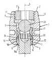
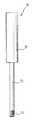
図1から図3に示されるように、骨固定装置は、第1の端部2と第1の端部に対向する第2の端部3とを有する、実質的に円筒状の受部1を含む。2つの端部は長手軸4に直交する。長手軸4と同軸に同軸ボア5が与えられ、同軸ボア5は、第1の端部2から、第2の端部3から予め定められた距離まで延在する。第2の端部3において開口部6が与えられ、その直径はボア5の直径より小さい。同軸ボア5は開口部6に向ってテーパ状である。示される実施例では、ボア5は球形部分7の形状にテーパ状である。 As shown in FIGS. 1 to 3, the bone anchoring device has a substantially cylindrical receiving
受部1は、第1の端部2から始まって第2の端部3の方向に前記第2の端部3から予め定められた距離まで延在する、U字型凹部8をさらに有する。U字型凹部によって、第1の端部2に向って終わる2つの自由脚部9,10が形成される。第1の端部2に隣接して、受部1は前記脚部9,10に雌ねじ11を含む。 The
骨固定要素13は、骨ねじを備えたシャンク14と、個別の部品として形成されて図1に示す組立てられた状態でシャンクに接続される、ヘッド部15とを含む。ヘッド部15は球状セグメント形外面部分16を有する。ヘッド部15のこの部分の半径は、受部1がヘッド部15を受取るとヘッド部15の球状外面16が第2の端部3の開口部6に隣接する球状部分7によって支持され、または開口部6の縁部によって支持されて、ヘッド部15の部分15aが開口部6から突出するような半径である。ヘッド部15に圧力がいまだ働いていない場合は、ヘッド部15は玉継手と同様に球状領域7において回転可能に保持される。 The
さらに、ボア5の内径よりわずかに小さい外径を備えた円筒状の構造を有する圧力要素17が与えられることにより、圧力要素が受部1のボア5に導入されて軸方向に動くことが可能である。圧力要素17は、第2の端部3の方に面する下側に球状凹部18を含み、その半径はヘッド部15の球状部分16の半径に対応する。圧力要素17は、長手軸4を横断して延在するU字型凹部19を反対側に有する。このU字型凹部の側面の直径は、受
部に受取られるロッド20が凹部19に挿入されてそこで横向きに導かれ得るように選択される。球状凹部19の深さは、組立てられた状態で、ロッドがU字型凹部の底に挿入されてそこに押付けられるときに圧力要素17がヘッド部15に圧力を及ぼすように、選択される。Furthermore, by providing a
骨固定装置は、脚部9,10の間にねじ込むことができる内ねじ21をさらに含み、ロッド20を固定し、かつ圧力要素17を介してヘッド部15に圧力を及ぼす。雌ねじ11と内ねじ21の協働ねじとは、いかなる公知のねじ形状も有することができる。しかしながら、平ねじまたは負の角ねじは、脚部9,10が扇形に開かないので外部ナットまたはリングの使用が不要になるという利点をもたらす。 The bone anchoring device further includes an
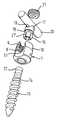
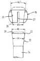
シャンク14およびヘッド部15の詳細がここで記載される。シャンク14はヘッド部15に受取られる端部22を含む。端部22は円錐台形状を有し、直径dsの自由端23の方に向って広くなる。シャンクの円錐形端部22の円錐角αは、シャンクがヘッド部に接続されるときに自動ロック接続が達成され得るように、好ましくは選択される。特に図2および図3に示すように、ヘッド部15は、平らにされた球形の輪郭を有し、第1の端部2の方に面する端部にボア24を含み、ボア24は受部の長手軸4と同軸であって、その直径は円錐形端部22の自由端23の最大直径dsよりわずかに大きい。ボア24は、円錐形の端部22が図1に示すように完全に挿入されたときヘッド部15から突出するように、円錐形端部22の外端部23を通って導くことができる。ヘッド部15は、中空の円錐台として形成された凹部25を受部の第2の端部3の方に向う側に含み、その寸法は、シャンクがヘッド部15に挿入されたときにシャンクの円錐形端部22の寸法と合うようになっている。円錐形凹部25の角度α’は好ましくは端部22の角度αに相当し、または角度αより大きい。凹部25によって形成される下側の開口部26の直径dbは、シャンクの円錐形端部22の自由端23の最大直径dsより小さい。 Details of the
図2および図3に示すように、ヘッド部15は複数の縦スリット27を有し、それらはシャンク端部22に面する端部に開いており、かつ外周方向に等距離に配列される。スリット27のサイズは、下側の開口部26が広がって円錐形端部22の挿入を可能にし、かつ挿入後にその端部を弾力的にクランプ締めすることができる程度に凹部25が広がることができるのに十分なサイズである。 As shown in FIGS. 2 and 3, the
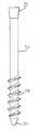
図4に示すように、円錐形端部の自由端23は、ヘッド部15への挿入を容易にするために面取り部28を有することができる。面取り部28は、圧力要素17の凹部18の湾曲と対になるよう曲げることができる。円錐形の凹部25はヘッド部15の全体にわたって延在することもできる。 As shown in FIG. 4, the
好ましくは、ヘッド部15の凹部25の円錐角αは、端部22の円錐角に対応しており、かつ円錐形端部22がヘッド部の凹部25に挿入されると自動ロック接続を達成するよう選択される。一旦自動ロック接続が確立されれば、円錐形端部を凹部25から除去するためには円錐形端部を凹部25に挿入するのに必要な力より大きい追加の力が必要となる。自動ロック効果を達成する円錐角は、好ましくは約2°から10°の間であって、より好ましくは約4°である。 Preferably, the cone angle α of the
第1の運転モードでは、好適なシャンク14が選択され、その端部22はヘッド部15に接続する。面取り部28によって、円錐形端部22を下側の開口部26を通ってのヘッド部に導入することが容易になる。端部22の挿入によって下側の開口部26が広げられ、円錐形凹部25はスリット27によって広がって、円錐形端部22全体の導入が可能となる。シャンクがヘッド部に導入されると自動ロック接続が確立されるように角度αが選択された場合、一旦シャンクがヘッド部に挿入されれば、ヘッド部が外れたり意図せず取
除かれたりすることはできない。In the first operating mode, a
次に、ヘッド部15が取り付けられたシャンク14から構成される骨固定要素13が第1の端部2から受部1に導入され、ねじ切られたシャンク14は受部の開口部6を通って、ヘッド部15が開口部6の縁部に対して配置されるまで導かれる。その後、圧力要素17が導入され、ねじ切られたシャンクが骨にねじ込まれる。次いで固定要素13に対する受部1の角位置が調節され、ロッド20が挿入される。次に内ねじ21をねじ込むことによりロッドが固定される。内ねじ21はロッド20に圧力を及ぼし、圧力要素17を押し下げる。圧力要素17は、シャンクの端部22の自由端23への当接部を形成する。この態様で、ヘッド部15は球状領域7または開口部6の縁部に対して押付けられ、その結果、開口部6の縁部がシャンクの端部22をクランプ締めするためのスリット27によりヘッド部を圧迫する。さらに、圧力要素17は端部22の自由端23を押し、円錐形状の端部22をヘッド部の円錐形凹部25に押し込み、それによりヘッド部とシャンクとの間に強固な接続が達成されて、同時にヘッド部はその回転位置にロックされる。 Next, a
上述の骨固定装置の部分は、好ましくは例えばチタンなどの生体互換性のある材料でできている。 The part of the bone anchoring device described above is preferably made of a biocompatible material such as titanium.
第2の運転モードにおいて、まずねじ切られたシャンク14が骨または脊椎にねじ込まれる。図1に示されるように、この目的のため、シャンク14はその自由端に六角形の凹部30など、ねじ回しのための公知の係合可能性を有する。次いで、あらかじめ緩く組み立てられたヘッド部15および圧力要素17とともに、受部1が骨から突出するシャンク14の円錐形端部22に押付けられる。これを達成するためには、ヘッド部15を円錐形端部に嵌め込む、すなわちヘッド部15がスリットにより広げられ、円錐形端部22に留付けられるのにいくらかの圧力が必要である。ヘッド部をシャンクに入れるのに必要な押圧力は、円錐角および/またはスリットによってもたらされる弾性に依存する。この状態で、ヘッド部が受部においてもなお回転可能である一方で、シャンクはヘッド部によってクランプ締めされる。次にロッド20が挿入され、ヘッド部15に対する受部1の角位置が調節される。その後、内ねじ21がロッド20を押付けるまで脚部9、10の間にねじ込まれ、それによりヘッド部15に圧力を及ぼす。圧力要素によってヘッド部15に及ぼされた圧力により、スロット付きヘッド部15はシャンク14に強固に接続されるかまたはクランプ締めされ、運動を防げ、同時にヘッド部15はその回転位置に固定される。 In the second mode of operation, the threaded
必要であれば、受部1はヘッド部15とともに、図8aから図8dおよび図9に示されるツールを用いて、原位置のままシャンクから分離され得る。まず、図8aに示されるように、内ねじおよびロッドが除去される。この状態で、ヘッド部15は受部1においてロック解除されるが、なおシャンクの端部22をクランプ締めしている。次に図8bに示されるように、ツール100が用いられて、ヘッド部15がもはや受部の下側の開口部6から突出しないように、ヘッド部15を受部1に押込む。 If necessary, the receiving
ツール100は長手バー101を含み、そこから2つのアーム102,103が直角の方向に延在する。アームのうち1つは、バーの部分105がアーム103上に突出して容易につかめるよう、バー101の自由端104からある距離の位置に固定される。示される実施例において、ツールが使用されているときはそれは上側のアーム103である。他のアーム102は長手バー101に摺動的に取り付けられ、アーム間の距離を変えるよう、他方端106の端部位置と所望の位置との間で上側のアーム103に向う方向に変動可能に固定することができる。少なくとも下側のアーム102は、シャンク14を取り囲むことができるようにフォーク形状である。下側のアーム102がバーの端部106に位置する場合、アーム間の距離は受部1の高さより大きい。
図8bに示されるように、使用中、ツールは下側のアーム102が端部位置にある状態で受部に適用される。次いで下側のアーム102が動かされて受部1の第2の端部3に対して押付けられ、そのため、図8cに示すようにヘッド部15が完全に受部内に入るまで受部1をヘッド部15に対して動かす。この状態でヘッド部には広がり得る空間があり、そのため図8dに示すように、受部およびヘッド部とともにシャンクからツールを引き離すときにシャンクの端部22を引き抜くことができる。 As shown in FIG. 8b, in use, the tool is applied to the receiving portion with the
変形もあり得る。例えば下側のアームの代りに上側のアーム103が摺動可能となり得る。摺動可能なアームはバーに固定される必要はなく、受部に対して手動で押付けることができる。 Variations are possible. For example, instead of the lower arm, the
端部22、ヘッド部15および受部1の寸法は、端部22とヘッド部15との間の自動ロック接続の摩擦力を克服するのに必要な力が手術中保たれるように選択される。 The dimensions of the
図5aから図5cまではシャンク14の変形を示す。図5aでは、シャンク14の直径dは円錐形部分22の最小直径より小さい。図5bでは、シャンク14の直径dは円錐形端部22の最小直径より大きい。図5cで、シャンクは先端部141に隣接するねじ切り部140および骨ねじのない部分142を含む。すべての変形において、円錐形端部22は、ヘッド部15の凹部25において受取り可能なように形成される。 FIGS. 5 a to 5 c show a deformation of the
図6はヘッド部の変形についての概略図を示す。ヘッド部15’は図1から図4に示す実施例のように、円錐台として形成される凹部25を有する。しかしながら、同軸ボア24’の直径は、シャンクの円錐形端部23の直径より小さい。したがって、凹部25の上部の壁は端部22に対する環状の当接部28を形成する。ボア24’の直径は、ねじ込みツールが端部22にアクセスできる程度に大きい。ヘッド部15が受部1とともに原位置のままでシャンク14から分離することができるよう、ヘッド部はヘッド部を保持するツールと係合するための係合手段を有し、そのため受部1がシャンクから引き離されるとき、ヘッド部は開口部6に対して引き寄せられ得ない。図7はツール30の例を示し、ツール30は、ハンドル31とハンドルから延在してねじ切り端部33を有するバー32とから構成される。この場合、ボア24’はねじ切り端部33との係合用内ねじを含む。使用において、内ねじ21およびロッドの除去後、したがってヘッド部15に対する圧力の解除後は、ヘッド部は、ねじ切られたボア24’にねじ切り先端部33をねじ込むことによりツール30によって保持され、同時に受部は手動でシャンクから引き離される。このように、シャンクの端部22はヘッド部15から引出される。本発明は上述の実施例に限定されない。さらなる変形が考えられる。例えば、本発明はねじ切りシャンクを有する固定要素に限定されず、フックから構成される固定要素にも適用することができる。この場合、フックの自由端が円錐形端部22を有する。 FIG. 6 shows a schematic view of the deformation of the head part. The head portion 15 'has a
さらに、シャンク14の形状および直径は変えることができ、骨ねじの長さも変えることができる。例えば、シャンクがねじなし部分を有する図5cの変形例は、図5aまたは図5bに示すシャンクにも適用することができる。 Furthermore, the shape and diameter of the
円錐形端部22の円錐角、および中空の円錐台の形状の凹部25は、自動ロック効果がないよう選択することができる。この場合、ヘッド部15のスリット26の数および形状は、ヘッド部15を円錐形端部22に留付けることができるよう選択しなければならない。 The conical angle of the
ヘッド部15のいくつかのスリットの代りに、1つのスリットのみを有することが可能であり、それはヘッド部の壁全体を通って長手方向に延在する。さらに、このように継続する1つのスリットを、図3に示すスリットに加えて有することも可能である。下側の開
口部26に対向する端部に向って開いた付加的なスリットが与えられてもよい。さらに、中空の円錐台として形成される凹部25がヘッド部15全体を通って延在し、そのためボア24または24’を省略することも可能である。Instead of several slits in the
他の変形例では、ヘッド部は、弾性をもたらす材料、例えば適切なプラスチック材料で形成される。この場合、スリットは省略されてもよい。 In other variations, the head portion is formed of a material that provides elasticity, such as a suitable plastic material. In this case, the slit may be omitted.
受部もまた変形することができる。ヘッド部15が外れ得ないように開口部6が十分に小さい限り、球状部分7の半径はヘッド部の半径より大きくてもよい。球状部分7の代りに、別の形状、例えば円錐形の形状を備えた部分が可能である。 The receiving part can also be deformed. As long as the
さらに、圧力要素17は異なる形状を有してもよい。圧力要素の長手方向の長さは、ロッドが挿入されるときU字型凹部19によって生成される脚部がロッドの上に突出するほど大きくてもよい。この場合、内部ナットが脚部9と10との間にねじ込まれた状態で圧力要素を介して個別にヘッド部15を固定し、ナットにねじ込まれる内ねじによって個別にロッドを固定することが可能である。 Furthermore, the
受部は骨プレートの一部であり得る。この場合、受部はU字型凹部を有さず、ヘッド部15への圧力は例えば内ねじ単独で生成することができる。 The receptacle can be part of a bone plate. In this case, the receiving part does not have a U-shaped recess, and the pressure to the
1 受部、2 第1の端部、3 第2の端部、4 長手軸、5 同軸ボア、7 球状部分、8 U字型凹部、14 シャンク、15 ヘッド部、16 セグメント形部分、17 圧力要素、22 端部、23 自由端。DESCRIPTION OF
Claims (10)
Translated fromJapanese骨または脊椎に固定されるシャンク(14)およびヘッド部(15)を含む骨固定要素を含み、ヘッド部は球状セグメント形状部分(16)を備える外面を有し、前記シャンク(14)および前記ヘッド部(15)は個別の部品であり、さらに、
第1の端部(2)、第1の端部に対向する第2の端部(3)、2つの端部を通過する長手軸(4)、長手軸に同軸のボア(5)、および、前記ヘッド部の球状セグメント形状部分(16)を受取るための第2の端部(3)に隣接する第1の領域(7)を含む受部(1)と、
前記ヘッド部を受部にロックするために前記ヘッド部(15)に対して圧力を及ぼす要素(17,20,21)とを含み、
前記ヘッド部は前記シャンクの自由端部(22)を受取るための中空の内部部分(25)を有し、前記ヘッド部および前記端部は、前記ヘッド部がロックされない間に端部が前記ヘッド部によって弾性的にクランプ締めされるよう形成される、骨固定装置。A bone anchoring device,
A bone anchoring element comprising a shank (14) and a head portion (15) secured to a bone or spine, the head portion having an outer surface with a spherical segment shaped portion (16), said shank (14) and said head Part (15) is an individual part;
A first end (2), a second end (3) opposite the first end, a longitudinal axis (4) passing through the two ends, a bore (5) coaxial with the longitudinal axis, and A receiving portion (1) including a first region (7) adjacent to a second end (3) for receiving a spherical segment-shaped portion (16) of the head portion;
Elements (17, 20, 21) that exert pressure on the head portion (15) to lock the head portion to a receiving portion;
The head portion has a hollow inner portion (25) for receiving the free end portion (22) of the shank, the end portion of the head portion and the end portion being positioned while the head portion is not locked. A bone anchoring device configured to be elastically clamped by a section.
Applications Claiming Priority (4)
| Application Number | Priority Date | Filing Date | Title |
|---|---|---|---|
| US69767005P | 2005-07-08 | 2005-07-08 | |
| EP05014840AEP1741396B1 (en) | 2005-07-08 | 2005-07-08 | Bone anchoring device |
| EP05014840.2 | 2005-07-08 | ||
| US60/697,670 | 2005-07-08 |
Publications (2)
| Publication Number | Publication Date |
|---|---|
| JP2007014787Atrue JP2007014787A (en) | 2007-01-25 |
| JP4980664B2 JP4980664B2 (en) | 2012-07-18 |
Family
ID=37752411
Family Applications (1)
| Application Number | Title | Priority Date | Filing Date |
|---|---|---|---|
| JP2006188382AExpired - Fee RelatedJP4980664B2 (en) | 2005-07-08 | 2006-07-07 | Bone fixation device |
Country Status (2)
| Country | Link |
|---|---|
| JP (1) | JP4980664B2 (en) |
| KR (1) | KR101147452B1 (en) |
Cited By (5)
| Publication number | Priority date | Publication date | Assignee | Title |
|---|---|---|---|---|
| JP2009261938A (en)* | 2008-04-22 | 2009-11-12 | Biedermann Motech Gmbh | Instrument, system and method for assembling bone anchoring device |
| JP2010515543A (en)* | 2007-01-10 | 2010-05-13 | ファセット ソリューションズ インコーポレイテッド | Taper lock fixing system |
| JP2013542774A (en)* | 2010-10-05 | 2013-11-28 | ダニエル エス. サベージ | Pedicle screw assembly and assembly method |
| JP2017535324A (en)* | 2014-10-21 | 2017-11-30 | グローバス メディカル インコーポレイティッド | Implantable orthopedic tools |
| CN109009384A (en)* | 2017-02-16 | 2018-12-18 | 华毅智能医疗器械(宁波)有限公司 | Polyaxial bone anchor system |
Families Citing this family (1)
| Publication number | Priority date | Publication date | Assignee | Title |
|---|---|---|---|---|
| KR100980459B1 (en)* | 2010-03-30 | 2010-09-07 | 주식회사 지에스메디칼 | Cervical screw |
Citations (2)
| Publication number | Priority date | Publication date | Assignee | Title |
|---|---|---|---|---|
| US20050049588A1 (en)* | 2003-08-28 | 2005-03-03 | Jackson Roger P. | Polyaxial bone screw with split retainer ring |
| US20050055026A1 (en)* | 2002-10-02 | 2005-03-10 | Biedermann Motech Gmbh | Bone anchoring element |
Family Cites Families (2)
| Publication number | Priority date | Publication date | Assignee | Title |
|---|---|---|---|---|
| JP3308271B2 (en)* | 1992-06-25 | 2002-07-29 | ジンテーズ アクチエンゲゼルシャフト,クール | Osteosynthesis fixation device |
| DE10164323C1 (en)* | 2001-12-28 | 2003-06-18 | Biedermann Motech Gmbh | Bone screw has holder element joined to shaft and possessing two free arms , with inner screw, slot, external nut, cavity and shoulder cooperating with attachment |
- 2006
- 2006-07-07JPJP2006188382Apatent/JP4980664B2/ennot_activeExpired - Fee Related
- 2006-07-07KRKR1020060063954Apatent/KR101147452B1/ennot_activeExpired - Fee Related
Patent Citations (3)
| Publication number | Priority date | Publication date | Assignee | Title |
|---|---|---|---|---|
| US20050055026A1 (en)* | 2002-10-02 | 2005-03-10 | Biedermann Motech Gmbh | Bone anchoring element |
| JP2006501908A (en)* | 2002-10-02 | 2006-01-19 | ビーダーマン・モテーク・ゲゼルシャフト・ミット・ベシュレンクタ・ハフツング | Fixed element |
| US20050049588A1 (en)* | 2003-08-28 | 2005-03-03 | Jackson Roger P. | Polyaxial bone screw with split retainer ring |
Cited By (10)
| Publication number | Priority date | Publication date | Assignee | Title |
|---|---|---|---|---|
| JP2010515543A (en)* | 2007-01-10 | 2010-05-13 | ファセット ソリューションズ インコーポレイテッド | Taper lock fixing system |
| JP2009261938A (en)* | 2008-04-22 | 2009-11-12 | Biedermann Motech Gmbh | Instrument, system and method for assembling bone anchoring device |
| TWI465225B (en)* | 2008-04-22 | 2014-12-21 | Biedermann Technologies Gmbh | Instrument for assembling a bone anchoring device |
| JP2013542774A (en)* | 2010-10-05 | 2013-11-28 | ダニエル エス. サベージ | Pedicle screw assembly and assembly method |
| JP2017535324A (en)* | 2014-10-21 | 2017-11-30 | グローバス メディカル インコーポレイティッド | Implantable orthopedic tools |
| US11172918B2 (en) | 2014-10-21 | 2021-11-16 | Globus Medical Inc. | Orthopedic tools for implantation |
| US11730462B2 (en) | 2014-10-21 | 2023-08-22 | Globus Medical, Inc. | Orthopedic tools for implantation |
| US12295560B2 (en) | 2014-10-21 | 2025-05-13 | Globus Medical, Inc. | Orthopedic tools for implantation |
| CN109009384A (en)* | 2017-02-16 | 2018-12-18 | 华毅智能医疗器械(宁波)有限公司 | Polyaxial bone anchor system |
| CN109009384B (en)* | 2017-02-16 | 2023-12-29 | 上海司农进出口有限公司 | Multi-axial bone anchor system |
Also Published As
| Publication number | Publication date |
|---|---|
| KR20070006614A (en) | 2007-01-11 |
| KR101147452B1 (en) | 2012-05-21 |
| JP4980664B2 (en) | 2012-07-18 |
Similar Documents
| Publication | Publication Date | Title |
|---|---|---|
| US8034089B2 (en) | Bone anchoring device | |
| US10426522B2 (en) | Receiving part for receiving a rod for coupling the rod to a bone anchoring element | |
| JP5613401B2 (en) | Receiving part for receiving the rod and connecting it to the bone anchoring element, and a bone anchoring device having such a receiving part | |
| JP5084195B2 (en) | Bone anchoring device | |
| JP5090678B2 (en) | Bone fixation device | |
| JP6045253B2 (en) | Polyaxial bone anchoring device | |
| JP5622387B2 (en) | Receiving part for receiving the rod and connecting it to the bone anchoring element, and a bone anchoring device having such a receiving part | |
| JP5385668B2 (en) | Instruments and systems for assembling bone fixation devices | |
| US7972364B2 (en) | Locking assembly for securing a rod member in a receiver part for use in spinal or trauma surgery, bone anchoring device with such a locking assembly and tool therefor | |
| JP2009056292A (en) | Bone anchoring device | |
| JP2010148874A (en) | Receiving part for receiving rod for coupling the rod to bone anchoring element and bone anchoring device with such receiving part | |
| US12232775B2 (en) | Anchoring assembly for anchoring a rod to a bone or a vertebra | |
| US12070248B2 (en) | Polyaxial bone anchoring device and system including an instrument and a polyaxial bone anchoring device | |
| TW201309256A (en) | Polyaxial bone anchoring device with enlarged pivot angle | |
| US9510868B2 (en) | Polyaxial bone anchoring device | |
| JP4980664B2 (en) | Bone fixation device | |
| JP2007537788A (en) | Multiple coaxial screw system | |
| EP1749489B1 (en) | Bone anchoring device |
Legal Events
| Date | Code | Title | Description |
|---|---|---|---|
| A621 | Written request for application examination | Free format text:JAPANESE INTERMEDIATE CODE: A621 Effective date:20090421 | |
| A131 | Notification of reasons for refusal | Free format text:JAPANESE INTERMEDIATE CODE: A131 Effective date:20110607 | |
| A601 | Written request for extension of time | Free format text:JAPANESE INTERMEDIATE CODE: A601 Effective date:20110906 | |
| A602 | Written permission of extension of time | Free format text:JAPANESE INTERMEDIATE CODE: A602 Effective date:20110909 | |
| A521 | Request for written amendment filed | Free format text:JAPANESE INTERMEDIATE CODE: A523 Effective date:20110927 | |
| TRDD | Decision of grant or rejection written | ||
| A01 | Written decision to grant a patent or to grant a registration (utility model) | Free format text:JAPANESE INTERMEDIATE CODE: A01 Effective date:20120321 | |
| A01 | Written decision to grant a patent or to grant a registration (utility model) | Free format text:JAPANESE INTERMEDIATE CODE: A01 | |
| A61 | First payment of annual fees (during grant procedure) | Free format text:JAPANESE INTERMEDIATE CODE: A61 Effective date:20120419 | |
| FPAY | Renewal fee payment (event date is renewal date of database) | Free format text:PAYMENT UNTIL: 20150427 Year of fee payment:3 | |
| R150 | Certificate of patent or registration of utility model | Ref document number:4980664 Country of ref document:JP Free format text:JAPANESE INTERMEDIATE CODE: R150 Free format text:JAPANESE INTERMEDIATE CODE: R150 | |
| FPAY | Renewal fee payment (event date is renewal date of database) | Free format text:PAYMENT UNTIL: 20150427 Year of fee payment:3 | |
| S111 | Request for change of ownership or part of ownership | Free format text:JAPANESE INTERMEDIATE CODE: R313113 | |
| S533 | Written request for registration of change of name | Free format text:JAPANESE INTERMEDIATE CODE: R313533 | |
| FPAY | Renewal fee payment (event date is renewal date of database) | Free format text:PAYMENT UNTIL: 20150427 Year of fee payment:3 | |
| R350 | Written notification of registration of transfer | Free format text:JAPANESE INTERMEDIATE CODE: R350 | |
| R250 | Receipt of annual fees | Free format text:JAPANESE INTERMEDIATE CODE: R250 | |
| R250 | Receipt of annual fees | Free format text:JAPANESE INTERMEDIATE CODE: R250 | |
| R250 | Receipt of annual fees | Free format text:JAPANESE INTERMEDIATE CODE: R250 | |
| R250 | Receipt of annual fees | Free format text:JAPANESE INTERMEDIATE CODE: R250 | |
| R250 | Receipt of annual fees | Free format text:JAPANESE INTERMEDIATE CODE: R250 | |
| R250 | Receipt of annual fees | Free format text:JAPANESE INTERMEDIATE CODE: R250 | |
| R250 | Receipt of annual fees | Free format text:JAPANESE INTERMEDIATE CODE: R250 | |
| R250 | Receipt of annual fees | Free format text:JAPANESE INTERMEDIATE CODE: R250 | |
| LAPS | Cancellation because of no payment of annual fees |