JP2007011873A - Interface device and interface method - Google Patents
Interface device and interface methodDownload PDFInfo
- Publication number
- JP2007011873A JP2007011873AJP2005193968AJP2005193968AJP2007011873AJP 2007011873 AJP2007011873 AJP 2007011873AJP 2005193968 AJP2005193968 AJP 2005193968AJP 2005193968 AJP2005193968 AJP 2005193968AJP 2007011873 AJP2007011873 AJP 2007011873A
- Authority
- JP
- Japan
- Prior art keywords
- signal
- unit
- reaction
- state
- user
- Prior art date
- Legal status (The legal status is an assumption and is not a legal conclusion. Google has not performed a legal analysis and makes no representation as to the accuracy of the status listed.)
- Pending
Links
Images


Classifications
- H—ELECTRICITY
- H04—ELECTRIC COMMUNICATION TECHNIQUE
- H04L—TRANSMISSION OF DIGITAL INFORMATION, e.g. TELEGRAPHIC COMMUNICATION
- H04L12/00—Data switching networks
- H04L12/28—Data switching networks characterised by path configuration, e.g. LAN [Local Area Networks] or WAN [Wide Area Networks]
- H04L12/2803—Home automation networks
- H04L12/2816—Controlling appliance services of a home automation network by calling their functionalities
- H04L12/282—Controlling appliance services of a home automation network by calling their functionalities based on user interaction within the home
- H—ELECTRICITY
- H04—ELECTRIC COMMUNICATION TECHNIQUE
- H04L—TRANSMISSION OF DIGITAL INFORMATION, e.g. TELEGRAPHIC COMMUNICATION
- H04L12/00—Data switching networks
- H04L12/28—Data switching networks characterised by path configuration, e.g. LAN [Local Area Networks] or WAN [Wide Area Networks]
- H04L12/2803—Home automation networks
- H04L12/2823—Reporting information sensed by appliance or service execution status of appliance services in a home automation network
- H—ELECTRICITY
- H04—ELECTRIC COMMUNICATION TECHNIQUE
- H04L—TRANSMISSION OF DIGITAL INFORMATION, e.g. TELEGRAPHIC COMMUNICATION
- H04L12/00—Data switching networks
- H04L12/28—Data switching networks characterised by path configuration, e.g. LAN [Local Area Networks] or WAN [Wide Area Networks]
- H04L12/2803—Home automation networks
- H04L2012/2847—Home automation networks characterised by the type of home appliance used
- H04L2012/285—Generic home appliances, e.g. refrigerators
Landscapes
- Engineering & Computer Science (AREA)
- Automation & Control Theory (AREA)
- Computer Networks & Wireless Communication (AREA)
- Signal Processing (AREA)
- Human Computer Interaction (AREA)
- User Interface Of Digital Computer (AREA)
- Computer And Data Communications (AREA)
- Feedback Control In General (AREA)
- Selective Calling Equipment (AREA)
Abstract
Translated fromJapaneseDescription
Translated fromJapanese本発明は、インタフェース装置およびインタフェース方法に関する。 The present invention relates to an interface device and an interface method.
近年、ネットワークに対応した情報家電を用いたホームネットワークの開発が進んでいる。これらの情報家電は、多くの便利な機能を有し、多様な使い方ができるように構成されている。しかし、ユーザは、多数の機能から所望の機能を選択しなければならいので、所望の機能が発見できない場合には、ユーザにとって不便であった。 In recent years, development of home networks using information appliances corresponding to networks has been progressing. These information appliances have many useful functions and are configured to be used in various ways. However, since the user must select a desired function from a large number of functions, it is inconvenient for the user when the desired function cannot be found.
そこで、従来から情報家電とユーザとの間のインタフェース装置が考えられている。例えば、音声やジェスチャーによる操作指示とその意味内容とをユーザごとに編集した辞書を備えたインタフェース装置がある(特許文献1)。 Therefore, conventionally, an interface device between an information appliance and a user has been considered. For example, there is an interface device including a dictionary in which operation instructions by voice and gestures and their meanings are edited for each user (Patent Document 1).
また、UPnP(Universal Plug and Play)またはUDDI(Universal Description Discovery and Integration) に代表されるディレクトリサービスを用いて、家電の機能をユーザ(クライアント機器)へ提示する装置がある(特許文献2)。 In addition, there is an apparatus that presents home appliance functions to a user (client device) using a directory service represented by UPnP (Universal Plug and Play) or UDDI (Universal Description Discovery and Integration) (Patent Document 2).
さらに、複数のクライアント機器が相互に連携する複数の機能を同時に扱う場合に、この連携機能に関する内容をクライアント機器がユーザに提供する方法がある(特許文献3)。この公知例では、クライアント機器がインタフェース装置として作用する。
しかし、家電の機能は設計者の独自のルールにて記述されているので、インタフェース装置がその家電機能をそのまま表現したとしても、通常、ユーザは理解できなかった。 However, since the function of the home appliance is described in the designer's original rules, even if the interface device expresses the home appliance function as it is, the user cannot usually understand it.
また、ユーザが理解することができる表現に変換するためには、インタフェース装置は、多様な機能の各々に対応する表現を含む辞書を予め備えていなければならない。これは、インタフェース装置の設定に手間が掛かり、かつ、インタフェース装置の汎用性を阻害する原因となる。例えば、特定の家電に関する辞書をインタフェース装置にインストールしなければならず、かつ、その特定の家電にしかインタフェース装置を利用することができなかった。 In addition, in order to convert the expression into an expression that can be understood by the user, the interface apparatus must be previously provided with a dictionary including expressions corresponding to each of various functions. This takes time to set up the interface device and hinders the versatility of the interface device. For example, a dictionary related to a specific home appliance must be installed in the interface device, and the interface device can only be used for the specific home appliance.
そこで、本発明の目的は、ユーザが様々な情報家電を簡単に操作し、ユーザがその情報家電の状態を簡単に知ることができるように情報家電とユーザとの間を仲介するインタフェース装置を提供することを目的とする。 SUMMARY OF THE INVENTION An object of the present invention is to provide an interface device that mediates between an information appliance and the user so that the user can easily operate various information appliances and the user can easily know the state of the information appliance. The purpose is to do.
本発明に係る実施形態に従ったインタフェース装置は、ユーザによって入力された制御コマンド、ネットワークからの制御コマンド、または電気製品自身の内部状態変化に基づいて、動作状態を変更し該状態信号を出力する電気製品と通信することができるインタフェース装置において、
前記状態信号を取得する信号取得部と、前記状態信号をユーザへ表現する表現部と、前記表現部からの通知を受けたユーザの反応を反応信号として取得する反応取得部と、前記状態信号と前記反応信号とを関連付けて登録する登録部と、関連付けられた前記状態信号と前記反応信号とを格納する蓄積部と、前記蓄積部に格納された前記状態信号と前記信号取得部によって取得された他の前記状態信号とを照合する第1の照合部と、前記蓄積部に格納された前記反応信号と前記反応取得部によって取得された他の前記反応信号とを照合する第2の照合部と、前記蓄積部に格納された前記状態信号を前記電気製品へ出力して該電気製品を操作する操作部とを備え、
前記他の状態信号を取得した場合に、前記第1の照合部が該他の状態信号と前記蓄積部に格納された前記状態信号とを照合し、これらの状態信号が対応する場合には、前記表現部が前記状態信号に関連付けられた前記反応信号をユーザへ表現し、これらの状態信号が対応しない場合には、前記表現部が前記他の状態信号をユーザへ表現し、このときユーザから取得した前記反応信号を前記他の状態信号と関連付けて登録する。An interface apparatus according to an embodiment of the present invention changes an operation state and outputs a state signal based on a control command input by a user, a control command from a network, or a change in an internal state of the electrical product itself. In an interface device capable of communicating with an electrical product,
A signal acquisition unit that acquires the state signal; an expression unit that expresses the state signal to a user; a reaction acquisition unit that acquires a user's reaction received from the expression unit as a reaction signal; and the state signal Acquired by a registration unit that associates and registers the reaction signal, an accumulation unit that stores the associated state signal and the reaction signal, and the state signal and the signal acquisition unit that are stored in the accumulation unit. A first collation unit that collates with the other state signal; a second collation unit that collates the reaction signal stored in the storage unit with the other reaction signal acquired by the reaction acquisition unit; An operation unit for operating the electrical product by outputting the status signal stored in the storage unit to the electrical product,
When the other status signal is acquired, the first verification unit compares the other status signal with the status signal stored in the storage unit, and when these status signals correspond, If the representation unit represents the reaction signal associated with the state signal to the user, and these state signals do not correspond, the representation unit represents the other state signal to the user, and at this time, from the user The acquired reaction signal is registered in association with the other state signal.
本発明に係る実施形態に従ったインタフェース装置は、ユーザによって入力された制御コマンド、ネットワークからの制御コマンド、あるいは電気製品自身の状態変化に基づいて、動作状態を変更し該状態信号を出力する電気製品と通信することができるインタフェース装置であって、
前記状態信号を取得する信号取得部と、前記状態信号をユーザへ表現する表現部と、前記表現部からの通知を受けたユーザの反応を反応信号として取得する反応取得部と、前記状態信号と前記反応信号とを関連付けて登録する登録部と、関連付けられた前記状態信号と前記反応信号とを格納する蓄積部と、前記蓄積部に格納された前記状態信号と前記信号取得部によって取得された他の前記状態信号とを照合する第1の照合部と、前記蓄積部に格納された前記反応信号と前記反応取得部によって取得された他の前記反応信号とを照合する第2の照合部と、前記蓄積部に格納された前記状態信号を前記電気製品へ出力して該電気製品を操作する操作部とを備え、
前記他の状態信号を取得した場合に、前記第1の照合部が該他の状態信号と前記蓄積部に格納された前記状態信号とを照合し、これらの状態信号が対応する場合には、前記表現部が前記状態信号に関連付けられた前記反応信号をユーザへ表現し、これらの状態信号が対応しない場合には、前記表現部が前記他の状態信号をユーザへ表現し、このときユーザから取得した前記反応信号を前記他の状態信号と関連付けて登録し、
前記他の反応信号を取得した場合に、前記第2の照合部が該他の反応信号と前記蓄積部に格納された前記反応信号とを照合し、これらの反応信号が対応する場合には、前記反応信号に関連付けられた前記状態信号を前記電気製品へ出力することを特徴とする。The interface device according to the embodiment of the present invention changes the operating state based on a control command input by the user, a control command from the network, or a change in the state of the electrical product itself, and outputs the state signal. An interface device capable of communicating with a product,
A signal acquisition unit that acquires the state signal; an expression unit that expresses the state signal to a user; a reaction acquisition unit that acquires a user's reaction received from the expression unit as a reaction signal; and the state signal Acquired by a registration unit that associates and registers the reaction signal, an accumulation unit that stores the associated state signal and the reaction signal, and the state signal and the signal acquisition unit that are stored in the accumulation unit. A first collation unit that collates with the other state signal; a second collation unit that collates the reaction signal stored in the storage unit with the other reaction signal acquired by the reaction acquisition unit; An operation unit for operating the electrical product by outputting the status signal stored in the storage unit to the electrical product,
When the other status signal is acquired, the first verification unit compares the other status signal with the status signal stored in the storage unit, and when these status signals correspond, If the representation unit represents the reaction signal associated with the state signal to the user, and these state signals do not correspond, the representation unit represents the other state signal to the user, and at this time, from the user Register the acquired reaction signal in association with the other state signal;
When the other reaction signal is acquired, the second matching unit compares the other reaction signal with the reaction signal stored in the storage unit, and when these reaction signals correspond, The state signal associated with the reaction signal is output to the electrical product.
本発明に係る実施形態に従ったインタフェースシステムは、ユーザによって入力された制御コマンド、ネットワークからの制御コマンド、あるいは電気製品自身の状態変化に基づいて、動作状態を変更し該状態信号を出力する電気製品と、該電気製品と通信することができるインタフェース装置とを含むインタフェースシステムであって、
前記電気製品は、前記状態信号に基づく動作状態の内容を示し、前記状態信号に関連付けられた説明記述を予め出力した後、前記状態信号を出力し、
前記インタフェース装置は、前記説明記述を予め取得した後、前記状態信号を取得する信号取得部と、前記説明記述をユーザへ表現する表現部と、前記表現部からの通知を受けたユーザの反応を反応信号として取得する反応取得部と、前記状態信号と前記反応信号とを関連付けて登録する登録部と、予め取得した前記状態信号および前記説明記述、並びに、前記登録部で関連付けられた前記状態信号および前記反応信号を格納する蓄積部と、前記蓄積部に格納された前記状態信号と前記信号取得部によって取得された他の前記状態信号とを照合する第1の照合部と、前記蓄積部に格納された前記反応信号と前記反応取得部によって取得された他の前記反応信号とを照合する第2の照合部と、前記蓄積部に格納された前記状態信号を前記電気製品へ出力して該電気製品を操作する操作部とを備え、
前記他の状態信号を取得した場合に、前記第1の照合部が該他の状態信号と前記蓄積部に格納された前記状態信号とを照合し、これらの状態信号が対応する場合には、前記表現部が前記状態信号に関連付けられた前記反応信号をユーザへ表現し、これらの状態信号が対応しない場合には、前記表現部は前記他の状態信号に関連付けられた前記説明記述をユーザへ表現し、このときユーザから取得した前記反応信号を前記他の状態信号と関連付けて登録し、
前記他の反応信号を取得した場合に、前記第2の照合部が該他の反応信号と前記蓄積部に格納された前記反応信号とを照合し、これらの反応信号が対応する場合には、前記反応信号に関連付けられた前記状態信号を前記電気製品へ出力することを特徴とする。An interface system according to an embodiment of the present invention is an electrical system that changes an operation state and outputs a state signal based on a control command input by a user, a control command from a network, or a state change of the electrical product itself. An interface system including a product and an interface device capable of communicating with the electrical product,
The electrical product shows the contents of the operation state based on the state signal, outputs the description description associated with the state signal in advance, and then outputs the state signal,
The interface device acquires the description description in advance, and then obtains a signal acquisition unit that acquires the status signal, an expression unit that expresses the description description to a user, and a reaction of the user who receives a notification from the expression unit. A reaction acquisition unit to acquire as a reaction signal, a registration unit to associate and register the state signal and the reaction signal, the state signal and the description description acquired in advance, and the state signal associated with the registration unit And an accumulator that stores the reaction signal, a first collator that collates the status signal stored in the accumulator with the other status signal acquired by the signal acquirer, and an accumulator A second collating unit that collates the stored reaction signal with the other reaction signal acquired by the reaction acquiring unit; and the status signal stored in the accumulating unit And output to an operation portion for operating the electrical products,
When the other status signal is acquired, the first verification unit compares the other status signal with the status signal stored in the storage unit, and when these status signals correspond, If the representation unit represents the reaction signal associated with the state signal to the user, and these state signals do not correspond, the representation unit displays the description description associated with the other state signal to the user. Expressing and registering the reaction signal acquired from the user at this time in association with the other state signal,
When the other reaction signal is acquired, the second matching unit compares the other reaction signal with the reaction signal stored in the storage unit, and when these reaction signals correspond, The state signal associated with the reaction signal is output to the electrical product.
本発明に係る実施形態に従ったインタフェースシステムは、ユーザによって入力された制御コマンド、ネットワークからの制御コマンド、あるいは電気製品自身の状態変化に基づいて、動作状態を変更し該状態信号を出力する電気製品と、該電気製品と通信することができるインタフェース装置とを含むインタフェースシステムであって、
前記電気製品は、前記状態信号に基づく動作状態の内容を示し、前記状態信号に関連付けられた説明記述、該電気製品の種別を示す種別情報と、前記状態信号とを出力し、
前記インタフェース装置は、複数の前記電気製品からそれぞれ前記説明記述、前記種別情報および前記状態信号を予め取得する信号取得部と、或る前記電気製品の前記説明記述と他の前記電気製品の前記説明記述とを照合する第1の照合部と、照合の結果、これらの説明記述が一致する場合に、これらの説明記述を1つの説明記述とし、前記複数の説明記述に関連する複数の前記種別情報をこの1つの説明記述に関連付けて登録する登録部と、複数の前記電気製品の前記種別情報および前記状態信号を前記説明記述ごとに予め格納する蓄積部と、ユーザの反応を反応信号として取得する反応取得部と、前記蓄積部に格納された前記説明記述と前記反応取得部によって取得された前記反応信号とを照合する第2の照合部と、照合の結果、前記説明記述と前記反応信号とが対応する場合に、該説明記述に関連付けられた前記複数の種別情報を表示する表示部と、前記複数の種別情報のうちユーザが選択した前記種別情報を有する前記電気製品に対して、前記説明記述に対応する前記状態信号を出力して該電気製品を操作する操作部とを備えている。An interface system according to an embodiment of the present invention is an electrical system that changes an operation state and outputs a state signal based on a control command input by a user, a control command from a network, or a state change of the electrical product itself. An interface system including a product and an interface device capable of communicating with the electrical product,
The electrical product indicates the contents of the operation state based on the status signal, outputs an explanation description associated with the status signal, type information indicating the type of the electrical product, and the status signal,
The interface device includes a signal acquisition unit that previously acquires the description description, the type information, and the status signal from a plurality of the electrical products, the description description of a certain electrical product, and the description of another electrical product. A plurality of type information related to the plurality of explanation descriptions, when the explanation description is matched as a result of the collation, and the explanation description is one explanation description. Is registered in association with this one description description, a storage unit that stores the type information and the state signal of the plurality of electrical products in advance for each description description, and obtains a user reaction as a reaction signal A response acquisition unit; a second verification unit that compares the explanation description stored in the storage unit with the reaction signal acquired by the reaction acquisition unit; When the description corresponds to the reaction signal, the display unit displays the plurality of type information associated with the description description, and the electric product includes the type information selected by the user from the plurality of type information On the other hand, an operation unit for operating the electric product by outputting the status signal corresponding to the description description is provided.
本発明に係る実施形態に従ったインタフェースシステムは、ユーザによって入力された制御コマンド、ネットワークからの制御コマンド、あるいは電気製品自身の状態変化に基づいて、動作状態を変更し該状態信号を出力する電気製品と、前記状態信号に基づく動作状態の内容を示し、前記状態信号に関連付けられた説明記述および複数の前記電気製品の複数の前記説明記述と関連付けられた連携状態信号を有し、複数の電気製品を連携して制御する機能連携制御部と、前記機能連携制御部を介して前記電気製品と通信するインタフェース装置とを含むインタフェースシステムであって、
前記機能連携制御部は、前記連携状態信号および該連携状態信号に関連付けられた前記複数の説明記述を出力し、
前記インタフェース装置は、前記連携状態信号および該連携状態信号に関連付けられた前記複数の説明記述を取得する信号取得部と、前記複数の説明記述をユーザへ表現する表現部と、前記表現部からの通知を受けたユーザの反応を反応信号として取得する反応取得部と、前記連携状態信号と前記反応信号とを関連付けて登録する登録部と、互いに関連付けられた前記連携状態信号、前記反応信号および前記複数の説明記述を格納する蓄積部と、前記蓄積部に格納された前記連携状態信号と前記信号取得部によって取得された他の前記連携状態信号とを照合する第1の照合部と、前記蓄積部に格納された前記反応信号と前記反応取得部によって取得された他の前記反応信号とを照合する第2の照合部と、前記蓄積部に格納された前記連携状態信号を前記機能連携制御部へ出力し、前記機能連携制御部を介して前記複数の電気製品を操作する操作部とを備えている。An interface system according to an embodiment of the present invention is an electrical system that changes an operation state and outputs a state signal based on a control command input by a user, a control command from a network, or a state change of the electrical product itself. A product and an operation state based on the state signal, and having a description description associated with the state signal and a plurality of state description associated with the plurality of description descriptions of the plurality of electrical products, An interface system including a function cooperation control unit that controls products in cooperation and an interface device that communicates with the electrical product via the function cooperation control unit,
The function linkage control unit outputs the linkage status signal and the plurality of explanation descriptions associated with the linkage status signal,
The interface device includes: a signal acquisition unit that acquires the cooperation state signal and the plurality of explanation descriptions associated with the cooperation state signal; an expression unit that represents the plurality of description descriptions to a user; and A reaction acquisition unit that acquires a reaction of the user who has received the notification as a reaction signal, a registration unit that associates and registers the cooperation state signal and the reaction signal, the cooperation state signal that is associated with each other, the reaction signal, and the An accumulator that stores a plurality of explanatory descriptions; a first collator that collates the linkage state signal stored in the accumulation unit with another linkage state signal acquired by the signal acquisition unit; and the accumulation A second collation unit that collates the reaction signal stored in the unit with the other reaction signal acquired by the reaction acquisition unit, and the linkage state stored in the storage unit Outputs No. to the functional coordination controller, and an operation unit for operating the plurality of electrical products through the functional coordination controller.
本発明に係る実施形態に従ったインタフェースシステムは、ユーザによって入力された制御コマンド、ネットワークからの制御コマンド、あるいは電気製品自身の状態変化に基づいて、動作状態を変更し該状態信号を出力する電気製品と、該電気製品と通信することができるインタフェース装置とを含むインタフェースシステムであって、
前記電気製品は、前記状態信号に基づく動作状態の内容を示し、前記状態信号に関連付けられた説明記述、該電気製品の種別を示す種別情報と、前記状態信号とを出力し、
前記インタフェース装置は、複数の前記電気製品からそれぞれ前記説明記述、前記種別情報および前記状態信号を予め取得する信号取得部と、或る前記電気製品の前記説明記述と他の前記電気製品の前記説明記述とを照合する第1の照合部と、照合の結果、これらの説明記述が一致する場合に、これらの説明記述を1つの説明記述とし、前記複数の説明記述に関連する複数の前記種別情報をこの1つの説明記述に関連付けて登録する登録部と、複数の前記電気製品の前記種別情報および前記状態信号を前記説明記述ごとに予め格納する蓄積部と、ユーザの反応を反応信号として取得する反応取得部と、前記蓄積部に格納された前記説明記述と前記反応取得部によって取得された前記反応信号とを照合する第2の照合部と、照合の結果、前記説明記述と前記反応信号とが対応する場合に、該説明記述に関連付けられた前記複数の種別情報を表示する表示部と、前記複数の種別情報のうちユーザが選択した前記種別情報を有する前記電気製品に対して、前記説明記述に対応する前記状態信号を出力して該電気製品を操作する操作部とを備えている。An interface system according to an embodiment of the present invention is an electrical system that changes an operation state and outputs a state signal based on a control command input by a user, a control command from a network, or a state change of the electrical product itself. An interface system including a product and an interface device capable of communicating with the electrical product,
The electrical product indicates the contents of the operation state based on the status signal, outputs an explanation description associated with the status signal, type information indicating the type of the electrical product, and the status signal,
The interface device includes a signal acquisition unit that previously acquires the description description, the type information, and the status signal from a plurality of the electrical products, the description description of a certain electrical product, and the description of another electrical product. A plurality of type information related to the plurality of explanation descriptions, when the explanation description is matched as a result of the collation, and the explanation description is one explanation description. Is registered in association with this one description description, a storage unit that stores the type information and the state signal of the plurality of electrical products in advance for each description description, and obtains a user reaction as a reaction signal A response acquisition unit; a second verification unit that compares the explanation description stored in the storage unit with the reaction signal acquired by the reaction acquisition unit; When the description corresponds to the reaction signal, the display unit displays the plurality of type information associated with the description description, and the electric product includes the type information selected by the user from the plurality of type information On the other hand, an operation unit for operating the electric product by outputting the status signal corresponding to the description description is provided.
本発明によるインタフェース装置は、ユーザが様々な情報家電を簡単に操作し、ユーザがその情報家電の状態を簡単に知ることができるように情報家電とユーザとの間を仲介することができる。 The interface apparatus according to the present invention can mediate between the information appliance and the user so that the user can easily operate various information appliances and the user can easily know the state of the information appliance.
以下、図面を参照して本発明に係る実施形態を説明する。以下の実施形態は、本発明を限定するものではない。 Embodiments according to the present invention will be described below with reference to the drawings. The following embodiments do not limit the present invention.
(第1の実施形態)
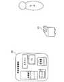
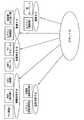
図1は、本発明に係る第1の実施形態に従ったインタフェース装置、情報家電機器およびユーザを示す観念図である。本実施形態では、インタフェース装置として親しみやすい身体性を有するロボット10が採用されている。情報家電機器20は、エアコン、冷蔵庫、テレビ、洗濯機、電子レンジ等の情報家電機器である。情報家電機器20は、ユーザによって入力された制御コマンド、ネットワークからの制御コマンド、あるいは電気製品自身の状態変化に基づいて、動作状態を変更し該状態信号を出力することができるように構成されている。状態信号は、情報家電機器20の動作状態を示す信号である。情報家電機器20は、この状態信号を入力することによってその状態信号が示す動作状態に移行する。また、情報家電機器20は、この状態信号を出力することによって、現在の自己の動作状態をロボット10に伝達することができる。例えば、ユーザがエアコンをリモコンでON状態にした場合、リモコンはエアコンを起動させるための制御コマンドを出力する。エアコンは、この制御コマンドを取得してON状態になるとともに、ON状態を示すこの状態信号をロボット10へ出力する。動作状態は、様々な情報家電機器20の任意の動作または状態を意味する。(First embodiment)
FIG. 1 is a conceptual diagram showing an interface device, an information home appliance, and a user according to the first embodiment of the present invention. In the present embodiment, the
図2は、ロボット10の内部構成を示すブロック図である。ロボット10は、信号取得部11、表現部12、反応取得部13、登録部14、蓄積部15、第1の照合部16、第2の照合部17および操作部18を備えている。 FIG. 2 is a block diagram showing the internal configuration of the
信号取得部11は、情報家電機器20から出力された状態信号を取得する。信号取得部11は、UPnPを用いて情報家電機器20のいずれかと通信接続することができる。 The
表現部12は、状態信号をユーザに対して表現し、あるいは、蓄積部15に格納された反応信号をユーザに対して表現する。表現方法は、ユーザが認識可能な任意の表現方法(音声、画像、ジェスチャー等)でよい。例えば、表現方法が音声である場合、表現部12はスピーカでよい。表現方法が画像である場合、表現部12はディスプレイでよい。表現方法がジェスチャーである場合、表現部12はロボット10の手、足または顔等の機構でよい。 The
反応取得部13は、表現部12から通知を受けたユーザの反応を反応信号として取得するように構成されている。反応信号は、ユーザの反応を電気的な信号に変換したものである。例えば、表現部12が状態信号を音声で表現したときに、ユーザがその音声に対して声を出して反応したとする。この場合、反応取得部13はマイクでよい。このマイクは、ユーザの声を反応信号として電気的な信号に変換する。ユーザがジェスチャーまたは顔の表情で応答した場合、反応取得部13はカメラでよい。このカメラは、ユーザのジェスチャーまたは顔の表情を反応信号として電気的な信号に変換する。 The
登録部14は、状態信号と反応信号とを関連付けて登録するように構成されている。例えば、表現部12が状態信号をユーザに対して表現し、その後一定期間内におけるユーザの反応を反応取得部13が取得する。登録部14は、このときの状態信号と反応信号とを関連付ける。関連付けは、状態信号および反応信号に同一の識別番号を付すればよい。識別番号は乱数または日時でよい。 The
蓄積部15は、登録部14で互いに関連付けられた状態信号および反応信号を格納する。蓄積部15は、任意の記憶媒体でよい。但し、蓄積部15は、書込みおよび読出し可能な記憶媒体である必要がある。 The
第1の照合部16は、蓄積部15に格納された状態信号と信号取得部11によって取得された他の状態信号とを照合する。照合はこれらの状態信号が同一信号か否かを判断することである。 The
第2の照合部17は、蓄積部15に格納された反応信号と反応取得部13によって取得された他の反応信号とを照合する。照合はこれらの反応信号が同一信号か否かを判断することである。 The
操作部18は、蓄積部15に格納された状態信号を情報家電機器20へ出力する。情報家電機器20は、状態信号を受けて自己の動作状態を変更する。 The
ロボット10は、UPnPによって任意の情報家電機器20と通信可能であるが、これらの情報家電機器20の情報を予め備えている必要は無い。従って、ロボット10は、情報家電機器20の辞書等を有していない。 The
以下、ロボット10の一連の動作を説明する。 Hereinafter, a series of operations of the
(状態信号および反応信号の登録動作)
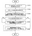
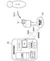
図3は、状態信号および反応信号の登録時におけるロボット10等の動作を示した概念図である。図4は、状態信号および反応信号の登録時におけるロボット10等の動作の流れを示すフロー図である。具体例として、エアコン22の操作を説明する。(Registering status signals and reaction signals)
FIG. 3 is a conceptual diagram showing the operation of the
まず、ロボット10は、初期状態であり、エアコン22の情報を有していないものとする。ユーザがリモコン21でエアコン22を操作し、暖房をON状態にする(S10)。このとき、エアコン22は、リモコン21から制御コマンドを取得し、暖房を動作させるとともに、状態信号をロボット10へ出力する。ロボット10は、UPnP経由でエアコン22からの状態信号を取得する(S20)。このとき、ロボット10は、エアコン22に関する情報を有していないので、状態信号を取得することができるものの、この状態信号の意味内容を知らない。 First, it is assumed that the
ロボット10は、状態信号を蓄積部15に格納するとともに、表現部12でこの状態信号を表現する(S30)。例えば、表現部12をスピーカとすると、表現部12は状態信号をそのまま音声として出力する。上述の通り家電の機能は設計者の独自のルールで記述されているので、このときロボット10が出力する音声は、ユーザには理解できない場合が多い。しかし、ユーザは自らエアコン22の暖房をON状態にしている。よって、ユーザは、ロボット10からの音声が、エアコン22の暖房をON状態にしたことに起因するロボット10の表現であることが分かる。そこで、ユーザは、ロボット10からの音声に反応して、“暖房入れたよ“と声で応答する。ロボット10は、一定期間内に行なわれた”暖房入れたよ“というユーザの反応を反応取得部13で取得し、この反応を応答信号へ変換する(S40)。次に、登録部14がこの反応信号とステップS20で取得された状態信号とを関連付ける(S50)。さらに、関連付けられた反応信号と状態信号とを蓄積部15へ格納する(S60)。このようにして、状態信号および反応信号の登録が完了する。 The
この登録動作は、エアコン22の他の様々な機能についても実行される。また、この登録動作は、他の情報家電機器20についても実行される。これにより、ロボット10は、様々な情報家電機器20の様々な機能に関する状態信号と、それらの状態信号に関連付けられた反応信号とを得ることができる。 This registration operation is also executed for various other functions of the
また、反応信号は、言語の種類(英語、日本語、フランス語等)を問わない。例えば、ユーザが英語で反応すれば、ロボット10はその英語を反応信号として状態信号と関連付けて登録するからである。さらには、反応信号は、特定のユーザのみが理解可能な暗号であってもよい。このように、ロボット10は、ユーザ独自の言語、表情、ジェスチャー等で状態信号を登録することができる。 The reaction signal may be any language type (English, Japanese, French, etc.). For example, if the user responds in English, the
(関連付けの強化)
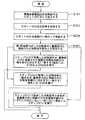
図5は、状態信号および反応信号の関連付けの強化時におけるロボット10等の動作を示した概念図である。図6は、この関連付けの強化時におけるロボット10等の動作の流れを示すフロー図である。(Strengthening association)
FIG. 5 is a conceptual diagram showing the operation of the
上記登録動作の終了後、さらに、ユーザがリモコン21でエアコン22を操作する(S70)。このとき、エアコン22は、リモコン21からの制御コマンドにしたがって動作するとともに、状態信号をロボット10へ出力する。ロボット10は、UPnP経由でエアコン22からの状態信号を取得する(S80)。このとき、ロボット10は、蓄積部15内に互いに関連付けられた状態信号および反応信号を格納している。そこで、第1の照合部16が、ステップS80で取得した状態信号と、蓄積部15内に格納された状態信号とを照合する(S90)。その結果、これらの状態信号が対応する(一致する)場合には、表現部14はその状態信号に関連付けられた反応信号をユーザへ表現する(S100)。例えば、ユーザがエアコン22の暖房を再度ON状態にした場合、ステップS80で取得した状態信号と蓄積部15内に格納された状態信号とは一致する。従って、ロボット10は、この状態信号に関連付けられた反応信号を、表現部12を介して出力する。即ち、ロボット10は“暖房入れたよ”とスピーカから音声を出力する。 After the completion of the registration operation, the user further operates the
これに対して、ユーザが“うん、暖房だね”と一定期間内に応答する(S101)と、ロボット10は、反応取得部13においてこの応答を反応信号に変換し、さらに、登録部14においてこの反応信号と状態信号とを関連付けて登録する(S102)。これにより、暖房をON状態にする状態信号に関連付けられた反応信号が増加する。また、“暖房つけたよ”および“うん、暖房だね”という反応のうち、“暖房”という文言が重複する。従って、ロボット10は、この状態信号と“暖房”という文言との関連付け(リンク)を強化することができる。 On the other hand, when the user responds “Yes, it is heating” within a certain period (S101), the
これらの状態信号が対応しない(一致しない)場合には、表現部14はステップS80で取得した状態信号をそのままユーザへ表現する(S110)。状態信号をそのままユーザへ表現した場合、図4のステップS40〜S60が再度実行される。これにより、ステップS80で取得した状態信号とユーザから取得した反応信号とを関連付けて登録することができる。例えば、ユーザがエアコン22の暖房をOFF状態にした場合、ステップS80で取得した状態信号と蓄積部15内に格納された状態信号とは一致しない。従って、ロボット10は、ステップS80で取得した状態信号を出力し、それに対するユーザの反応“暖房消したよ”を取得する。さらに、ロボット10は、ステップS80で取得した状態信号と“暖房消したよ”に対応する反応信号を関連付けて登録する。 If these state signals do not correspond (do not match), the
このように、ロボット10は、様々な状態信号と様々な反応信号とを関連付け、これらを蓄積することができる。さらに、ロボット10は、1つの状態信号に対して複数の反応信号を関連付けることによって、状態信号とユーザの反応との関連付け(リンク)を強化することができる。 Thus, the
(操作時の動作)
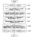
図7は、ロボット10を介して情報家電機器20を操作する場合におけるロボット10等の動作を示した概念図である。図8は、ロボット10を介して情報家電機器20を操作する場合におけるロボット10等の動作の流れを示すフロー図である。(Operation during operation)
FIG. 7 is a conceptual diagram showing the operation of the
状態信号および反応信号の登録動作、および/または、状態信号と反応信号との関連付け強化を繰り返すことによって、或る程度の量の状態信号および反応信号が蓄積部15内に蓄積される。そこで、ユーザは、情報家電機器20に状態信号を入力することなく、ロボット10に対して反応信号のみを入力する(S120)。例えば、ユーザは、音声で“暖房入れて”と言うだけでよい。 By repeating the registration operation of the state signal and the reaction signal and / or strengthening the association between the state signal and the reaction signal, a certain amount of the state signal and the reaction signal is accumulated in the
ロボット10は、反応信号取得部13で反応信号を取得する(S130)。例えば、反応取得部13が“暖房入れて”という音声を取得し、これを反応信号に変換する。次に、第2の照合部17がこの反応信号と蓄積部15に格納された反応信号とを照合する(S140)。例えば、第2の照合部17が“暖房入れて”に対応する反応信号を蓄積部15内で検索する。このとき、反応取得部13により取得された反応信号と、蓄積部15に格納された反応信号とは、完全に一致する必要は無く、或る程度一致すればよい。例えば、“暖房入れて”の“暖房入れ”という文言と、“暖房入れたよ”の“暖房入れ”という文言とが一致すれば、第2の照合部17は、これらの反応信号が対応すると判断してよい。 The
その結果、これらの反応信号が対応する場合、この反応信号に関連付けられた状態信号を情報家電機器20へ出力する(S150)。このとき、関連付け強化によって“暖房”という文言がこの状態信号と強く関連付けられている場合、ロボット10は、確認のために表現部12から“暖房、暖房”と音声を出力してもよい。次に、情報家電機器20は、状態信号に従って動作状態を変更する。例えば、エアコンは暖房をON状態にする。これにより、ユーザは、音声で命令するだけでロボット10をインタフェースとして情報家電機器20を操作することができる。 As a result, when these reaction signals correspond, a state signal associated with the reaction signal is output to the information home appliance 20 (S150). At this time, when the word “heating” is strongly associated with this state signal due to the strengthening of association, the
反応取得部13により取得された反応信号と蓄積部15に格納された反応信号とが対応しない場合、ロボット10は、動作しなくてもよい。しかし、情報家電機器20の操作が不可能であることをユーザに通知するために、ロボット10は情報家電機器20を操作できないことを表現部12から通知してもよい(S160)。この通知は、ロボット10に予め設定しておいてもよい。 If the reaction signal acquired by the
情報家電機器20を操作できないことを知ったユーザは、状態信号および反応信号の登録動作および関連付けの強化動作を再度実行すればよい。 The user who knows that the
第1の実施形態において、インタフェース装置としてロボット10を採用した。しかし、インタフェース装置は、固定された端末等であってもよい。 In the first embodiment, the
第1の実施形態において、反応信号は、音声を電気信号に変換したものであった。しかし、反応信号は、音声を磁気信号または光学的信号に変換したものであってもよい。 In the first embodiment, the reaction signal is obtained by converting sound into an electric signal. However, the reaction signal may be a sound signal converted into a magnetic signal or an optical signal.
第1の実施形態おいて、反応取得部13は、一定期間内に行なわれたユーザの反応を取得する。しかし、反応取得部13は、ユーザが特定の合図を行なうまでユーザの反応を取得し続けてもよい。特定の合図とは、ユーザの発する特定の音声(例えば、拍手など)でよい。 In the first embodiment, the
第1の実施形態は、反応取得部13により取得された反応信号と、蓄積部15に格納された反応信号との完全一致を要求していない。そのため、第2の照合部17は、これらの反応信号の異同を類似度として算出してもよい。類似度は、例えば、信号が音声であれば一般的な音声認識で用いられる類似度を用いてもよいし、その他、音のピッチ、音の大小、音のパターンなどの音の特徴量の類似度を用いてもよい。第2の照合部17は、類似度の最も高い反応信号と関連付けられた状態信号を選択する。ロボット10は、選択された状態信号を情報家電機器20へ出力する。 The first embodiment does not require a perfect match between the reaction signal acquired by the
ここで、この状態信号がユーザの所望するものでない場合、ユーザはその旨をロボットへ伝えればよい。例えば、ユーザが“暖房入れて”とロボット10に命令したときに、ロボット10が誤って冷房をON状態にする状態信号をエアコン22へ出力したと仮定する。この場合、ユーザは、“それは冷房だよ”とロボット10へ伝える。ロボット10は、“それは冷房だよ”という音声を反応信号へ変換し、この反応信号と冷房をON状態にする状態信号とを関連付けて登録する。これにより、ロボット10を学習させることができる。 Here, if the status signal is not what the user desires, the user may tell the robot to that effect. For example, it is assumed that when the user instructs the
このように、本実施形態によれば、ユーザは、ユーザ自身の言語、表情、ジェスチャー等を用いてロボット10に対して自然に応対するだけでロボット10を学習させることができ、さらにユーザ自身の言語、表情、ジェスチャー等を用いてこのロボット10に命令するだけで情報家電機器20を容易に操作することができる。 As described above, according to the present embodiment, the user can learn the
本実施形態におけるロボット10は、情報家電機器20の情報(例えば、辞書等)を必要としない。従って、ロボット10は、様々な情報家電機器20に対応することができ、汎用性が高い。また、このようなロボット10は、量産に適合し、低コストで生産することができる。 The
(第2の実施形態)
図9は、本発明に係る実施形態に従ったロボット30の内部構成を示すブロック図である。第2の実施形態において、ロボット30は、車輪と、移動距離および移動方向を測定する車軸エンコーダと、インタフェース装置の周辺にある障害物を検出する超音波センサと、インタフェース装置の存在する地域のマップ情報とを備えている。これにより、ロボット30は、自己の位置を特定し、指定された位置へ障害物を回避しつつ自律的に移動することができる。ロボット30は、状態信号を出力した情報家電機器の設置場所へ移動することによって、どの情報家電機器の状態信号または反応信号を表現しているかをユーザへ知らせることができる。あるいは、ロボット30は、ユーザのいる場所へ移動しつつ状態信号または反応信号を表現してもよい。これにより、ユーザは、ロボット30が出力する反応信号を容易に聞き、あるいは、見ることができる。(Second Embodiment)
FIG. 9 is a block diagram showing an internal configuration of the
また、ロボット30は、情報家電機器20の状態を示す文章を単語ごとに関連付けて登録する。さらに、ロボット30は複数の単語を組み合わせる文章生成部19をさらに備えている。これにより、ロボット30は、様々な状態信号に対して反応信号を応用することができる。第2の実施形態では、情報家電機器の具体例として洗濯機23を用いている。 In addition, the
(状態信号および反応信号の登録動作)
図10は、状態信号および反応信号の登録時におけるロボット30等の動作の流れを示すフロー図である。ロボット30、情報家電機器20およびユーザの関係を示す観念図は、図1、図3、図5および図7と同様であるので省略する。(Registering status signals and reaction signals)
FIG. 10 is a flowchart showing the flow of the operation of the
まず、ロボット30は、初期状態であり、洗濯機23の情報を有していないものとする。ユーザが洗濯機23を操作し、洗濯を開始する(S11)。このとき、洗濯機23は、ユーザの操作によって洗濯を開始させるとともに、状態信号をロボット30へ出力する。ロボット30は、UPnP経由で洗濯機23からの状態信号を取得する(S21)。このとき、ロボット30は、洗濯機23に関する情報を有していないので、状態信号を取得することができるものの、この状態信号の意味内容を知らない。 First, it is assumed that the
ロボット30は、状態信号を蓄積部15に格納するとともに、表現部12でこの状態信号を表現する(S31)。上述の通り家電の機能は設計者の独自のルールで記述されているので、このときロボット10が出力する音声は、ユーザには理解できない場合が多い。しかし、ユーザは自ら洗濯機23を操作している。よって、ユーザは、ロボット30からの音声が、洗濯を開始したことに起因するロボット30の表現であることが分かる。そこで、ユーザは、ロボット30からの音声に反応して、“洗濯始めたよ“と声で応答する。ロボット30は、一定期間内に行なわれた”洗濯始めたよ“というユーザの反応を反応取得部13で取得し、この反応を応答信号へ変換する(S41)。 The
次に、登録部14がこの反応信号に含まれる単語とステップS21で取得された状態信号の部分とを関連付ける(S51)。状態信号は、情報家電機器20の種類およびその情報家電機器の状態に関する情報を含む。例えば、情報家電機器20の種類は、例えば、“WASHER(洗濯)”を意味する。情報家電機器20の状態は、例えば、“START(開始)”を意味する。また、反応信号は情報家電機器の種類およびその情報家電機器の状態に関する複数の単語を含む文章を示す。例えば、“洗濯始めたよ”という反応信号は、情報家電機器の種類に関する単語として“洗濯”と、情報家電機器の状態に関する単語として“始めたよ”という2つの単語を含むと認識される。 Next, the
そこで、登録部14は、反応信号に含まれている各単語とこれらの単語のそれぞれに対応する情報家電機器の種類またはその情報家電機器の状態とを関連付けて登録する。例えば、登録部14は、反応信号の“洗濯”と状態信号の“WASHER”とを関連付け、反応信号の“始めたよ”と状態信号の“START”とを関連付ける。 Therefore, the
互いに関連付けられた反応信号の単語および状態信号の部分は、蓄積部15へ格納される(S61)。このようにして、状態信号および反応信号の登録が完了する。 The word of the reaction signal and the part of the state signal that are associated with each other are stored in the storage unit 15 (S61). In this way, registration of the status signal and the reaction signal is completed.
第1の実施形態と同様に、この登録動作は、洗濯機23の他の様々な機能についても実行される。また、反応信号は、言語の種類(英語、日本語、フランス語等)を問わない。 Similar to the first embodiment, this registration operation is also executed for various other functions of the
尚、上述の通り、通常、状態信号は設計者の独自のルールで記述されているが、第2の実施形態では、便宜的に、状態信号を英語で表わしている。 As described above, the status signal is normally described in the designer's own rules, but in the second embodiment, the status signal is expressed in English for convenience.
(関連付けの強化)
図11は、この関連付けの強化時におけるロボット10等の動作の流れを示すフロー図である。(Strengthening association)
FIG. 11 is a flowchart showing the flow of the operation of the
上記登録動作の終了後、さらに、ユーザが洗濯機23を操作する。あるいは、洗濯が終了し洗濯機23の状態が変化する(S71)。このとき、洗濯機23は、ユーザの操作にしたがって動作し、もしくは、洗濯が終了する。これとともに、そのときの状態信号をロボット30へ出力する。ロボット30は、UPnP経由で洗濯機23からの状態信号を取得する(S81)。このとき、ロボット30は、蓄積部15内に単語ごとに関連付けられた状態信号および反応信号部分を格納している。そこで、第1の照合部16が、ステップS81で取得した状態信号と、蓄積部15内に格納された状態信号部分とを照合する(S91)。 After the registration operation is completed, the user further operates the
その結果、ステップS81で取得した状態信号が、蓄積部15内に格納された複数の状態信号部分の組合せに対応する(一致する)場合には、文章生成部19が、その複数の状態信号部分に関連付けられた総ての単語を組み合わせた文章を生成する(S105)。表現部14は文章生成部19で生成された文章を反応信号としてユーザへ表現する(S205)。例えば、ユーザが洗濯を開始状態にした場合、ステップS81で取得した状態信号は、蓄積部15内に格納された状態信号部分 “WASHER”および “START”の組み合わせに一致する。従って、文章生成部19は、この状態信号部分に関連付けられた単語“洗濯”および “始めたよ”を組み合わせた文章を生成する。表現部12は、この文章を反応信号として出力する。即ち、ロボット10は“洗濯始めたよ”とスピーカから音声を出力する。 As a result, when the state signal acquired in step S81 corresponds to (matches) the combination of the plurality of state signal parts stored in the
これに対して、ユーザが“うん、洗濯始まったね”と一定期間内に応答する(S106)と、ロボット30は、反応取得部13においてこの応答を反応信号に変換し、さらに、登録部14においてこの反応信号と状態信号とを単語ごとに関連付けて登録する(S107)。これにより、“WASHER” を示す状態信号部分および“START” を示す状態信号部分のそれぞれに関連付けられた単語が増加する。また、“洗濯始めたよ”および“うん、洗濯始まったね”という反応のうち、“洗濯”という文言が重複する。従って、ロボット30は、“WASHER” を示す状態信号部分と“洗濯”という単語との関連付け(リンク)を強化することができる。 On the other hand, when the user responds within a certain period of time, “Yes, laundry has started” (S106), the
ステップS81で取得した状態信号の一部分のみが、蓄積部15内に格納された状態信号部分に対応する(一致する)場合には、表現部14は、ステップS81で取得した状態信号のうち一致しない部分と、その状態信号のうち一致する部分に関連付けられた単語とを組み合わせてユーザへ表現する(S108)。例えば、洗濯が終了した場合、ステップS81で取得した状態信号のうち“WASHER”は、蓄積部15内に格納された状態信号部分 “WASHER” と一致するものの、状態信号のうち“FINISH(終了)”は、蓄積部15内に格納された状態信号部分“START(開始)”に一致しない。従って、ロボット30は、“WASHER”を示す状態信号部分に関連付けられた単語“洗濯”と、“FINISH”を示す状態信号を組み合わせた文章を、表現部12を介して出力する。状態信号は、上述の通り、音声で出力してもユーザは理解できない。従って、ロボット30は“洗濯***”とスピーカから音声を出力する。尚、“***”は、“FINISH”を示す状態信号を音声化したものを示す。 When only a part of the state signal acquired in step S81 corresponds to (matches) the state signal portion stored in the
これに対し、図10のステップS41〜S61を再度実行する。これにより、ステップS81で取得した状態信号のうち未登録の部分とユーザから取得した反応信号の単語とをさらに関連付けて登録することができる。例えば、ユーザが“洗濯終わったよ”と反応する。第2の照合部17によって反応信号のうち“洗濯”という単語は既に登録されていることが分かる。従って、反応信号のうち“終わったよ”という単語が、ステップS81で取得した状態信号のうち未登録の部分“FINISH”に対応することが分かる。そこで、登録部14は、反応信号のうち“終わったよ”という単語と、ステップS81で取得した状態信号のうち“FINISH”を意味する部分とを関連付けて登録する。 On the other hand, steps S41 to S61 in FIG. 10 are executed again. Thereby, the unregistered portion of the state signal acquired in step S81 and the word of the reaction signal acquired from the user can be further associated and registered. For example, the user reacts “washing is finished”. The
ステップS81で取得した状態信号の全体が、蓄積部15内に格納された状態信号部分のいずれにも対応しない(一致しない)場合には、表現部14はステップS81で取得した状態信号をそのままユーザへ表現する(S111)。その後、図10のステップS41〜S61が再度実行される。これにより、ステップS81で取得した状態信号とユーザから取得した反応信号とを単語ごとに関連付けて登録することができる。 If the entire status signal acquired in step S81 does not correspond to (matches) any of the status signal parts stored in the
(通知動作)
図12は、情報家電機器20の動作状態が変化した時におけるロボット30等の動作の流れを示すフロー図である。(Notification action)
FIG. 12 is a flowchart showing the operation flow of the
まず、情報家電機器20の動作状態が変化すると、情報家電機器20は、状態信号をロボット30に対して出力する(S121)。例えば、洗濯機23において洗濯が終了したとする。このとき、洗濯機23は、“WASHER FINISH”を意味する状態信号を出力する。 First, when the operating state of the
ロボット30は、UPnP経由で状態信号を取得する(S131)。これとともに、ロボット30は、洗濯機23へ向かって移動する(S235)。次に、第1の照合部16がこの状態信号と蓄積部15に格納された状態信号部分とを照合する(S141)。例えば、第1の照合部16は、“WASHER”および“FINISH”のそれぞれに対応する状態信号部分を蓄積部15内で検索する。 The
その結果、ステップS131で取得した状態信号が、蓄積部15内に格納された複数の状態信号部分の組合せに対応する(一致する)場合には、図11のステップS105およびS205が実行される。 As a result, when the state signal acquired in step S131 corresponds to (matches) the combination of the plurality of state signal parts stored in the
ステップS131で取得した状態信号の一部分のみが、蓄積部15内に格納された状態信号部分に対応する(一致する)場合には、図11のステップS108が実行される。ステップS131で取得した状態信号の全体が、蓄積部15内に格納された状態信号部分のいずれにも対応しない(一致しない)場合には、図11のステップS111が実行される。ステップS205、S108およびS111は、ロボット30が洗濯機23の近傍に到着した後に実行されることが好ましい。 If only a part of the state signal acquired in step S131 corresponds to (matches) the state signal part stored in the
第2の実施形態によれば、ロボット30は、情報家電機器20の状態を示す文章を単語ごとに関連付けて登録する。さらに、ロボット30は複数の単語を組み合わせる文章生成部19をさらに備えている。これにより、ロボット30は、様々な状態信号に対して反応信号を応用することができる。 According to the second embodiment, the
ロボット30は、状態信号を出力した情報家電機器の設置場所へ移動することによって、どの情報家電機器の状態信号または反応信号を表現しているかをユーザへ知らせることができる。 The
さらに、第2の実施形態は、第1の実施形態の効果をも有する。 Furthermore, the second embodiment also has the effects of the first embodiment.
(第3の実施形態)
第3の実施形態では、状態信号および反応信号の登録時に、ロボット10は、状態信号とともにその状態信号と予め関連付けられた説明記述を獲得する。図13は、情報家電機器として電子レンジ24の説明記述を示した図である。図14は、説明記述の内容を示す図である。(Third embodiment)
In the third embodiment, when the status signal and the reaction signal are registered, the
図13のコマンドは、状態信号を含む命令である。パラメータは、命令に付随する設定値や状態である。説明記述は、各コマンドに付随して予め電子レンジ24内に格納されている。図14に示すように、説明記述は、情報家電機器の種別およびその状態を示している。説明記述は、UPnPにおけるDevice DescriptionまたはService Descriptionに該当する。Device Descriptionは、情報家電機器単位の説明記述である。Service Descriptionは、情報家電機器の各機能(サービス)単位の記述である。図14では、情報家電機器の種別として“電子レンジ”とし、その状態として“オーブンで加熱“としている。この記述説明は、状態信号と予め関連付けられている。ロボット10の構成は、第1の実施形態のロボット10と同様でよい。 The command in FIG. 13 is an instruction including a status signal. The parameter is a setting value or state associated with the command. The explanation description is stored in advance in the
(状態信号、説明記述および反応信号の登録時)
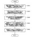
図15は、状態信号、説明記述および反応信号の登録時におけるロボット10等の動作を示した概念図である。図16は、状態信号、説明記述および反応信号の登録時におけるロボット10等の動作の流れを示すフロー図である。まず、ロボット10は、初期状態であり、電子レンジ24の情報を有していないものとする。ユーザが電子レンジ24を操作し、オーブンを起動させる(S12)。このとき、電子レンジ24は、状態信号とともに、この状態信号に関連付けられた説明記述を出力する。ロボット10は、UPnP経由で電子レンジ24からの状態信号および説明記述を取得する(S22)。ロボット10は、電子レンジ24に関する情報を有していないので、状態信号を取得することができるものの、この状態信号の意味内容を知らない。(When registering status signal, description and reaction signal)
FIG. 15 is a conceptual diagram showing the operation of the
ロボット10は、状態信号および説明記述を蓄積部15に格納するとともに、表現部12でこの説明記述を表現する(S32)。例えば、表現部12をスピーカとすると、表現部12は説明記述を音声として出力する。例えば、表現部12は“オーブンで加熱”と表現する。説明記述は、図14に示すようにユーザに理解できる言語で記述されているので、このときロボット10が出力する音声によって、ユーザは、電子レンジ24の状態を理解することができる。しかし、これは、ユーザ自身の言葉とは異なる。そこで、ユーザは、ロボット10からの音声に反応して、“オーブンつけたよ“と声で応答する。ロボット10は、一定期間内に行なわれた”オーブンつけたよ“というユーザの反応を反応取得部13で取得し、この反応を応答信号へ変換する(S42)。次に、登録部14がこの反応信号とステップS22で取得された状態信号または説明記述とを関連付ける(S52)。さらに、関連付けられた反応信号、状態信号および説明記述を蓄積部15へ格納する(S62)。このようにして、状態信号、説明記述および反応信号の登録が完了する。 The
(状態信号、説明記述および反応信号の関連付けの強化)
状態信号、説明記述および反応信号の関連付けの強化は、第1の実施形態とほぼ同様である。但し、ステップS90の後、状態信号が一致しない場合、ステップS110において、ロボット10は、状態信号の代わりに、説明記述を表現する。(Enhanced association of status signal, description and reaction signal)
The strengthening of the association of the status signal, the description description, and the reaction signal is almost the same as that in the first embodiment. However, if the state signals do not match after step S90, the
(操作時の動作)
操作時の動作は、第1の実施形態と同様である。(Operation during operation)
The operation at the time of operation is the same as that of the first embodiment.
第3の実施形態は、第1の実施形態と同様の効果を有する。さらに、第3の実施形態では、情報家電機器20が予め状態信号と関連付けられた記述説明を格納している。従って、ロボット10は、状態信号を表現することなく、記述説明を表現するので、ユーザは、反応信号の登録を容易に行うことができる。即ち、ユーザは、ロボット10を容易に学習させることができる。 The third embodiment has the same effect as the first embodiment. Furthermore, in 3rd Embodiment, the
(第4の実施形態)
本発明に係る第4の実施形態によるインタフェースシステムは、図1に示すロボット10および情報家電機器20でよい。ロボット10は図2に示す構成と同様の構成でよい。情報家電機器20の機能(状態信号)はUPnPにより公開され、ロボット10が、UPnPによりこの状態信号を収集する。即ち、情報家電機器20がUPnPデバイスであり、ロボット10がUPnPコントロールポイント(UPnP‐CP)であってよい。(Fourth embodiment)
The interface system according to the fourth embodiment of the present invention may be the
ロボット10は、蓄積部15内に図17に示すような分類表を格納している。図17に示す分類表は、家電に搭載される機能を2つのカテゴリに分類し説明するものである。第1のカテゴリは、人や環境に関連する物理単位作用のカテゴリであり、例えば、人間の五感に関係する“光、音、匂い、味、触覚、熱”、環境に影響する“液体、気体、動き、生物、存在”および、“電気、量、時間”等である。第2のカテゴリは、第1のカテゴリに対する物理的な作用を示すカテゴリであり、第1のカテゴリの“光”に対しては“表示、照明、印刷”等である。第1のカテゴリおよび第2のカテゴリは、それぞれ互いに関連付けられている。例えば、第1のカテゴリ“光”は、第2のカテゴリ“表示、照明、印刷”等に関連付けられている。第1のカテゴリ“音”は、第2のカテゴリ“音響再生、音声録音、喚起音生成”等に関連付けられている。この分類表は、事前にロボット10に格納しておくか、あるいは、情報家電機器20から取得した情報をもとにロボット10が作成する。 The
情報家電機器20は、自身が搭載する各機能を、上記各分類にて表現し、説明記述として格納する。例えば、テレビには、モニタ、スピーカ、などが搭載されている。モニタであれば、“第1のカテゴリ(光)、第2のカテゴリ(映像表示)”、スピーカであれば、“第1のカテゴリ(音)、第2のカテゴリ(音響再生)”の様に表現する。 The
また、情報家電機器20は、それぞれの自己の種別を示す種別情報、この種別情報に関連する状態信号およびこの種別情報に関連する説明記述を有している。種別情報は、例えば、エアコン、テレビ等の情報家電機器20の種類であってよい。さらに、種別情報は、エアコンの温度測定部、エアコンの暖房部、エアコンの除菌部、テレビの画面、テレビの音声出力部(スピーカ)等のように情報家電機器20内の部分の種類であってもよい。 In addition, the
状態信号および説明記述は、第3の実施形態のそれらと同様でよい。 The status signal and the explanation description may be the same as those in the third embodiment.
以下、第4の実施形態によるインタフェースシステムの動作を説明する。 The operation of the interface system according to the fourth embodiment will be described below.
(種別信号、状態信号および記述説明の登録動作)
図18は、種別信号、状態信号および記述説明の登録時におけるロボット10等の動作の流れを示すフロー図である。(Registration operation of type signal, status signal and description)
FIG. 18 is a flowchart showing the flow of operations of the
まず、複数の情報家電機器20が予めロボット10へ種別信号、状態信号および説明記述を出力する(S410)。ロボット10は、UPnP経由でこれらの情報家電機器20からの種別信号、状態信号および説明記述を取得する(S420)。 First, a plurality of
次に、第1の照合部16が、或る情報家電機器20の説明記述を他の情報家電機器20の説明記述と照合する(S430)。照合の結果、複数の説明記述が一致する場合に、登録部14は、これらの説明記述を1つの説明記述とし、これらの説明記述に関連する複数の種別情報および複数の状態信号をこの1つの説明記述に関連付けて登録する(S440)。例えば、ロボット10は、種別情報“エアコンの温度測定部”に関連する説明記述“温度測定する”、および、種別情報“冷蔵庫の温度測定部”に関連する説明記述“温度測定する”を取得したと仮定する。このとき、状態信号は、“温度測定する”を示す信号であるので、説明記述とともに取得したとする。この場合、2つの説明記述“温度測定する”は一致するので、登録部14は、“温度測定する”という1つの状態信号に対して2つの種別情報“エアコンの温度測定部”および “冷蔵庫の温度測定部”を関連付けて登録する。この登録部14で登録された種別情報および説明記述は、蓄積部15に格納される(S460)。このとき、図19に示すように、分類表の“熱”の欄に“エアコンの温度測定部”および “冷蔵庫の温度測定部”が“温度測定”という説明記述に関連付けられて格納される。 Next, the
図20は、説明記述(物理機能)、種別情報およびロボット10との関係を示す概念図である。例えば、説明記述“情報表示”に対しては、3つの種別情報“テレビ(画面)”、“時計(表示部)”およびDSC(画面)“が関連付けられている。説明記述“温度測定”に対しては、2つの種別情報“エアコン(温度測定部)”および“冷蔵庫(温度測定部)”が関連付けられている。このように、蓄積部15は、種別情報を説明記述ごとに分類して格納している。 FIG. 20 is a conceptual diagram illustrating the relationship between the description description (physical function), the type information, and the
(操作時の動作)
図21は、操作時のインタフェースシステムの動作の流れを示すフロー図である。まず、ユーザは、所望する機能をロボット10に対して命令する。ここで言うユーザとは、インタフェース装置の操作をする利用者、もしくは、インタフェース装置内部のアプリケーションプログラムなどを指す。このとき、ロボット10は、ユーザの命令を反応信号として取得する(S470)。次に、第2の照合部17が、蓄積部15に格納された説明記述と反応取得部13によって取得された反応信号とを照合する(S480)。照合の結果、これらの説明記述と反応信号とが対応する場合に、表示部12は説明記述に関連付けられた複数の種別情報を表示する(S490)。例えば、ユーザの命令(反応信号)が“温度を知りたい”であった場合、表示部12は、温度に関する説明記述“温度測定”に関連付けられた “エアコン(温度測定部)”および“冷蔵庫(温度測定部)“という2つの種別情報を表示する。(Operation during operation)
FIG. 21 is a flowchart showing an operation flow of the interface system during operation. First, the user instructs the
さらに、ユーザがこれらの種別情報のいずれかを選択した場合、操作部18は、選択された種別情報を有する情報家電機器20に対して説明記述を出力する(S491)。情報家電機器20は、この説明記述に従って動作する。例えば、ユーザが冷蔵庫の温度でなく、室温を知りたい場合には、ユーザは“エアコン(温度測定部)”を選択する。操作部18は、説明記述“温度測定”に対応する状態信号をエアコンへ出力する。エアコンは、室内の温度を測定する温度測定部で気温を測定し、その結果をロボット10へ返す。ロボット10は、気温を表示部12で表示する。これにより、ユーザは室温を知ることができる。 Furthermore, when the user selects any of these type information, the
第4の実施形態によれば、ロボット10は、情報家電機器20の物理的な機能(説明記述)ごとに情報家電機器20の種別情報を格納している。よって、ユーザは、個々の情報家電機器20が有する機能を知る必要が無く、機能のみを命令することによってロボット10からその機能を有する情報家電機器20を知得することができる。 According to the fourth embodiment, the
第4の実施形態は、第2の実施形態と組み合わせてもよい。それによって、ロボット10は、取得した説明記述を文章生成部19(図9参照)に入力し、文章生成部19によって生成された文章をユーザに表示することができる。 The fourth embodiment may be combined with the second embodiment. Thereby, the
(第5の実施形態)
図22は、本発明に係る第5の実施形態に従ったインタフェース装置(ロボット)10、情報家電機器20、機能連携制御部30およびユーザを示す観念図である。(Fifth embodiment)
FIG. 22 is a conceptual diagram showing the interface device (robot) 10, the
機能連携制御部30は、情報家電機器20の説明記述、情報家電機器20の状態信号および連携状態信号を予め格納している。説明記述は、情報家電機器20の状態信号に基づく動作状態の内容を示し、情報家電機器20の状態信号に関連付けられている。1つの連携状態信号は、複数の情報家電機器の複数の説明記述と関連付けられている。 The function
機能連携制御部30の例としては、特開2004−320747号公報に記載されたクライアントがある。ロボット10および情報家電機器20の構成は、第1の実施形態のそれらと同様でよい。 An example of the function
(連携状態信号、説明記述および反応信号の登録時)
図23は、連携状態信号、説明記述および反応信号の登録時におけるロボット10等の動作の流れを示すフロー図である。まず、ユーザが機能連携制御部30を介して複数の情報家電機器を操作する(S510)。このとき、機能連携制御部30は、状態信号を複数の情報家電機器へ出力するとともに、連携状態信号および該連携状態信号に関連付けられた複数の説明記述をロボット10へ出力する(S520)。この説明記述は、複数の情報家電機器へ出力した状態信号に関する説明である。ロボット10は、連携状態信号および該連携状態信号に関連付けられた複数の説明記述を取得する。例えば、連携状態信号が“XXX”に関連付けられた第1の説明記述が“テレビにスーパーインポーズする”という音声であり、第2の説明記述が“(洗濯物を取り出す画像)”であると仮定する。連携状態信号は、家電の連携機能を設計する設計者の独自のルールにて記述されているので、インタフェース装置においては一般に連携状態信号(例えば、XXX)が何であるか理解できない。(When registering linkage status signal, description and reaction signal)
FIG. 23 is a flowchart showing the flow of the operation of the
次に、ロボット10は、取得した複数の説明記述を表現部12においてユーザへ表現する(S530)。表現部12からの通知を受けたユーザが反応する。反応取得部13は、ユーザの反応を反応信号として取得する(S540)。例えば、表現部12は、第1の説明記述“テレビにスーパーインポーズする”という音声を出力しつつ、第2の説明記述“洗濯の状態を通知する”様子を音声や画像で表示する。ユーザはこれに対して、“洗濯の終了通知だ”とロボット10へ発話する。反応取得部13は、このユーザの音声を反応信号として直接取得するか、あるいは、その音声を情報処理した結果を反応信号として取得する。 Next, the
次に、ロボット10は、登録部14において連携状態信号と反応信号とを関連付けて登録する(S550)。蓄積部15は、互いに関連付けられた連携状態信号、反応信号および複数の説明記述を格納する(S560)。 Next, the
(操作時の動作)
図24は、操作時の動作でのロボット10、情報家電機器20、機能連携制御部30およびユーザを示す観念図である。図25は、操作時におけるロボット10等の動作の流れを示すフロー図である。(Operation during operation)
FIG. 24 is a conceptual diagram showing the
ユーザがロボット10へ命令する(S570)。ロボット10は、反応取得部13でこの命令を反応信号として取得する(S580)。そして、第2の照合部は、反応取得部13で取得した反応信号と蓄積部15に格納された反応信号とを照合する(S590)。このとき、これらの反応信号が対応する場合、その反応信号に関連付けられた連携状態信号を機能連携制御部30へ出力する(S591)。これにより、機能連携制御部30は、複数の情報家電機器へ状態信号を出力する(S592)。例えば、反応信号が“洗濯の終了通知してくれ”である場合、ロボット10は連携状態信号“XXX”に対応する制御信号を機能連携制御部30へ出力する。これにより、機能連携制御部30が、テレビおよび洗濯機のそれぞれへ“画面にスーパーインポーズする”および“洗濯終了通知”を意味する制御信号を出力する。 The user instructs the robot 10 (S570). The
次に、ロボット10は、第1の照合部16において機能連携制御部30から取得した他の連携状態信号と蓄積部15に格納された連携状態信号とを照合する(S593)。例えば、洗濯終了後、洗濯機は、“洗濯終了”を意味する状態信号を機能連携制御部30へ出力する。機能連携制御部30は、テレビの画面に“(洗濯物を取り出す画像)”や“洗濯が終了しました”という文字などを表示し、これとともに、連携状態信号“XXX”をロボット10へ出力する。ロボット10は、連携状態信号“XXX”を蓄積部15に格納された連携状態信号と照合する。連携状態信号“XXX”は、応答信号 “洗濯の終了通知だ”と関連付けられているので、ロボット10は、ユーザに対して“洗濯の終了通知だ”という反応信号を音声で出力する(S594)。これにより、ユーザは、洗濯物を取り出す画像がテレビに表示されていることが分かる。 Next, the
このように、第5の実施形態では、ユーザは、ロボット10を介して機能連携制御部30を制御することができる。ロボット10は、各情報家電機器の機能の意味を理解する必要がないだけでなく、それらの組み合わせにより構成されるサービスの意味も理解する必要がない。このため、情報家電機器の設計とロボット10の設計を独立して行うことができる。 Thus, in the fifth embodiment, the user can control the function
第5の実施形態は、第2の実施形態と組み合わせてもよい。それによって、ロボット10は、取得した説明記述を文章生成部19(図9参照)に入力し、文章生成部19によって生成された文章をユーザに表示することができる。 The fifth embodiment may be combined with the second embodiment. Thereby, the
なお、本発明は上記実施形態そのままに限定されるものではなく、実施段階ではその要旨を逸脱しない範囲で構成要素を変形して具体化できる。また、上記実施形態に開示されている複数の構成要素の適宜な組み合わせにより、種々の発明を形成できる。例えば、実施形態に示される全構成要素から幾つかの構成要素を削除してもよい。さらに、異なる実施形態にわたる構成要素を適宜組み合わせてもよい。 Note that the present invention is not limited to the above-described embodiment as it is, and can be embodied by modifying the components without departing from the scope of the invention in the implementation stage. In addition, various inventions can be formed by appropriately combining a plurality of components disclosed in the embodiment. For example, some components may be deleted from all the components shown in the embodiment. Furthermore, constituent elements over different embodiments may be appropriately combined.
10 ロボット
11 信号取得部
12 表現部
13 反応取得部
14 登録部
15 蓄積部
16 第1の照合部
17 第2の照合部
18 操作部
20 情報家電機器DESCRIPTION OF
Claims (12)
Translated fromJapanese前記状態信号を取得する信号取得部と、
前記状態信号をユーザへ表現する表現部と、
前記表現部からの通知を受けたユーザの反応を反応信号として取得する反応取得部と、
前記状態信号と前記反応信号とを関連付けて登録する登録部と、
関連付けられた前記状態信号と前記反応信号とを格納する蓄積部と、
前記蓄積部に格納された前記状態信号と前記信号取得部によって取得された他の前記状態信号とを照合する第1の照合部と、
前記蓄積部に格納された前記反応信号と前記反応取得部によって取得された他の前記反応信号とを照合する第2の照合部と、
前記蓄積部に格納された前記状態信号を前記電気製品へ出力して該電気製品を操作する操作部とを備え、
前記他の状態信号を取得した場合に、前記第1の照合部が該他の状態信号と前記蓄積部に格納された前記状態信号とを照合し、これらの状態信号が対応する場合には、前記表現部が前記状態信号に関連付けられた前記反応信号をユーザへ表現し、これらの状態信号が対応しない場合には、前記表現部が前記他の状態信号をユーザへ表現し、このときユーザから取得した前記反応信号を前記他の状態信号と関連付けて登録することを特徴とするインタフェース装置。In an interface device capable of communicating with an electrical product that changes an operation state and outputs a status signal based on a control command input by a user, a control command from a network, or an internal state change of the electrical product itself,
A signal acquisition unit for acquiring the state signal;
An expression unit for expressing the state signal to a user;
A reaction acquisition unit that acquires a reaction of a user who has received a notification from the expression unit as a reaction signal;
A registration unit for registering the state signal and the reaction signal in association with each other;
An accumulator for storing the associated status signal and the reaction signal;
A first collation unit that collates the state signal stored in the storage unit and the other state signal acquired by the signal acquisition unit;
A second collation unit that collates the reaction signal stored in the accumulation unit with the other reaction signal acquired by the reaction acquisition unit;
An operation unit for operating the electrical product by outputting the status signal stored in the storage unit to the electrical product;
When the other status signal is acquired, the first verification unit compares the other status signal with the status signal stored in the storage unit, and when these status signals correspond, If the representation unit represents the reaction signal associated with the state signal to the user, and these state signals do not correspond, the representation unit represents the other state signal to the user, and at this time, from the user An interface device, wherein the acquired response signal is registered in association with the other state signal.
前記状態信号を取得する信号取得部と、
前記状態信号をユーザへ表現する表現部と、
前記表現部からの通知を受けたユーザの反応を反応信号として取得する反応取得部と、
前記状態信号と前記反応信号とを関連付けて登録する登録部と、
関連付けられた前記状態信号と前記反応信号とを格納する蓄積部と、
前記蓄積部に格納された前記状態信号と前記信号取得部によって取得された他の前記状態信号とを照合する第1の照合部と、
前記蓄積部に格納された前記反応信号と前記反応取得部によって取得された他の前記反応信号とを照合する第2の照合部と、
前記蓄積部に格納された前記状態信号を前記電気製品へ出力して該電気製品を操作する操作部とを備え、
前記他の状態信号を取得した場合に、前記第1の照合部が該他の状態信号と前記蓄積部に格納された前記状態信号とを照合し、これらの状態信号が対応する場合には、前記表現部が前記状態信号に関連付けられた前記反応信号をユーザへ表現し、これらの状態信号が対応しない場合には、前記表現部が前記他の状態信号をユーザへ表現し、このときユーザから取得した前記反応信号を前記他の状態信号と関連付けて登録し、
前記他の反応信号を取得した場合に、前記第2の照合部が該他の反応信号と前記蓄積部に格納された前記反応信号とを照合し、これらの反応信号が対応する場合には、前記反応信号に関連付けられた前記状態信号を前記電気製品へ出力することを特徴とするインタフェース装置。In an interface device capable of communicating with an electrical product that changes an operation state and outputs a status signal based on a control command input by a user, a control command from a network, or an internal state change of the electrical product itself,
A signal acquisition unit for acquiring the state signal;
An expression unit for expressing the state signal to a user;
A reaction acquisition unit that acquires a reaction of a user who has received a notification from the expression unit as a reaction signal;
A registration unit for registering the state signal and the reaction signal in association with each other;
An accumulator for storing the associated status signal and the reaction signal;
A first collation unit that collates the state signal stored in the storage unit and the other state signal acquired by the signal acquisition unit;
A second collation unit that collates the reaction signal stored in the accumulation unit with the other reaction signal acquired by the reaction acquisition unit;
An operation unit for operating the electrical product by outputting the status signal stored in the storage unit to the electrical product;
When the other status signal is acquired, the first verification unit compares the other status signal with the status signal stored in the storage unit, and when these status signals correspond, If the representation unit represents the reaction signal associated with the state signal to the user, and these state signals do not correspond, the representation unit represents the other state signal to the user, and at this time, from the user Register the acquired reaction signal in association with the other state signal;
When the other reaction signal is acquired, the second matching unit compares the other reaction signal with the reaction signal stored in the storage unit, and when these reaction signals correspond, An interface device that outputs the status signal associated with the reaction signal to the electrical product.
前記第1の照合部は、他の前記状態信号に含まれる前記情報家電機器の種類と前記蓄積部に蓄積された前記情報家電機器の種類とを照合し、他の前記状態信号に含まれる前記情報家電機器の状態に関する情報と前記蓄積部に蓄積された前記情報家電機器の状態に関する情報とを照合し、
対応する前記情報家電機器の種類に関連付けられた単語と対応する前記情報家電機器の状態に関連付けられた単語とを組み合わせる文章生成部をさらに備えたことを特徴とする請求項1または請求項2に記載のインタフェース装置。When the status signal includes information regarding the type of the information home appliance and the state of the information home appliance, and the reaction signal indicates a sentence including a plurality of words regarding the type of the information home appliance and the state of the information home appliance, The registration unit registers each word included in the reaction signal in association with the type of the information home appliance corresponding to each of these words and the state of the information home appliance,
The first checking unit checks the type of the information home appliance included in the other state signal and the type of the information home appliance stored in the storage unit, and is included in the other state signal. Collating the information on the state of the information home appliance with the information on the state of the information home appliance stored in the storage unit,
3. The sentence generation unit that combines a word associated with a corresponding type of the information home appliance and a word associated with a state of the corresponding information home appliance, according to claim 1 or 2. The interface device described.
移動距離および移動方向を測定する車軸エンコーダと、
前記インタフェース装置の周辺にある障害物を検出する超音波センサと、
前記インタフェース装置の存在する地域のマップ情報とを備え、
前記状態信号を出力した前記情報家電機器のある位置へ移動することを特徴とする請求項1または請求項2に記載のインタフェース装置。Wheels,
An axle encoder that measures travel distance and travel direction;
An ultrasonic sensor for detecting an obstacle around the interface device;
Map information of the area where the interface device exists,
The interface apparatus according to claim 1, wherein the interface apparatus moves to a position of the information home appliance that has output the status signal.
移動距離および移動方向を測定する車軸エンコーダと、
前記インタフェース装置の周辺にある障害物を検出する超音波センサと、
前記インタフェース装置の存在する地域のマップ情報とを備え、
ユーザのいる位置へ移動することを特徴とする請求項1または請求項2に記載のインタフェース装置。Wheels,
An axle encoder that measures travel distance and travel direction;
An ultrasonic sensor for detecting an obstacle around the interface device;
Map information of the area where the interface device exists,
The interface apparatus according to claim 1, wherein the interface apparatus moves to a position where a user is present.
前記電気製品は、前記状態信号に基づく動作状態の内容を示し、前記状態信号に関連付けられた説明記述を予め出力した後、前記状態信号を出力し、
前記インタフェース装置は、
前記説明記述を予め取得した後、前記状態信号を取得する信号取得部と、
前記説明記述をユーザへ表現する表現部と、
前記表現部からの通知を受けたユーザの反応を反応信号として取得する反応取得部と、
前記状態信号と前記反応信号とを関連付けて登録する登録部と、
予め取得した前記状態信号および前記説明記述、並びに、前記登録部で関連付けられた前記状態信号および前記反応信号を格納する蓄積部と、
前記蓄積部に格納された前記状態信号と前記信号取得部によって取得された他の前記状態信号とを照合する第1の照合部と、
前記蓄積部に格納された前記反応信号と前記反応取得部によって取得された他の前記反応信号とを照合する第2の照合部と、
前記蓄積部に格納された前記状態信号を前記電気製品へ出力して該電気製品を操作する操作部とを備え、
前記他の状態信号を取得した場合に、前記第1の照合部が該他の状態信号と前記蓄積部に格納された前記状態信号とを照合し、これらの状態信号が対応する場合には、前記表現部が前記状態信号に関連付けられた前記反応信号をユーザへ表現し、これらの状態信号が対応しない場合には、前記表現部は前記他の状態信号に関連付けられた前記説明記述をユーザへ表現し、このときユーザから取得した前記反応信号を前記他の状態信号と関連付けて登録し、
前記他の反応信号を取得した場合に、前記第2の照合部が該他の反応信号と前記蓄積部に格納された前記反応信号とを照合し、これらの反応信号が対応する場合には、前記反応信号に関連付けられた前記状態信号を前記電気製品へ出力することを特徴とするインタフェースシステム。Based on a control command input by a user, a control command from the network, or a change in the internal state of the electrical product itself, the electrical product that changes the operating state and outputs the status signal can communicate with the electrical product. In an interface system including an interface device,
The electrical product shows the contents of the operation state based on the state signal, outputs the description description associated with the state signal in advance, and then outputs the state signal,
The interface device includes:
A signal acquisition unit for acquiring the state signal after acquiring the description in advance;
An expression unit for expressing the explanation description to a user;
A reaction acquisition unit that acquires a reaction of a user who has received a notification from the expression unit as a reaction signal;
A registration unit for registering the state signal and the reaction signal in association with each other;
An accumulator that stores the state signal and the description described in advance, and the state signal and the reaction signal associated with the registration unit;
A first collation unit that collates the state signal stored in the storage unit and the other state signal acquired by the signal acquisition unit;
A second collation unit that collates the reaction signal stored in the accumulation unit with the other reaction signal acquired by the reaction acquisition unit;
An operation unit for operating the electrical product by outputting the status signal stored in the storage unit to the electrical product;
When the other status signal is acquired, the first verification unit compares the other status signal with the status signal stored in the storage unit, and when these status signals correspond, If the representation unit represents the reaction signal associated with the state signal to the user, and these state signals do not correspond, the representation unit displays the description description associated with the other state signal to the user. Expressing and registering the reaction signal acquired from the user at this time in association with the other state signal,
When the other reaction signal is acquired, the second matching unit compares the other reaction signal with the reaction signal stored in the storage unit, and when these reaction signals correspond, An interface system that outputs the status signal associated with the reaction signal to the electrical product.
前記電気製品は、前記状態信号に基づく動作状態の内容を示し、前記状態信号に関連付けられた説明記述、該電気製品の種別を示す種別情報と、前記状態信号とを出力し、
前記インタフェース装置は、
複数の前記電気製品からそれぞれ前記説明記述、前記種別情報および前記状態信号を予め取得する信号取得部と、
或る前記電気製品の前記説明記述と他の前記電気製品の前記説明記述とを照合する第1の照合部と、
照合の結果、これらの説明記述が一致する場合に、これらの説明記述を1つの説明記述とし、前記複数の説明記述に関連する複数の前記種別情報をこの1つの説明記述に関連付けて登録する登録部と、
複数の前記電気製品の前記種別情報および前記状態信号を前記説明記述ごとに予め格納する蓄積部と、
ユーザの反応を反応信号として取得する反応取得部と、
前記蓄積部に格納された前記説明記述と前記反応取得部によって取得された前記反応信号とを照合する第2の照合部と、
照合の結果、前記説明記述と前記反応信号とが対応する場合に、該説明記述に関連付けられた前記複数の種別情報を表示する表示部と、
前記複数の種別情報のうちユーザが選択した前記種別情報を有する前記電気製品に対して、前記説明記述に対応する前記状態信号を出力して該電気製品を操作する操作部とを備えたインタフェースシステム。Based on a control command input by the user, a control command from the network, or a change in the internal state of the electrical product itself, an electrical product that changes the operating state and outputs the status signal to the network, and the electrical product via the network In an interface system including an interface device capable of communicating,
The electrical product indicates the contents of the operation state based on the status signal, outputs an explanation description associated with the status signal, type information indicating the type of the electrical product, and the status signal,
The interface device includes:
A signal acquisition unit for acquiring in advance the explanation description, the type information, and the status signal from each of the plurality of electrical products;
A first collation unit that collates the explanation description of a certain electrical product with the explanation description of another electrical product;
When these explanation descriptions match as a result of collation, these explanation descriptions are regarded as one explanation description, and a plurality of types of information related to the plurality of explanation descriptions are registered in association with the one explanation description. And
An accumulator that stores the type information and the status signal of the plurality of electrical products in advance for each explanation description;
A reaction acquisition unit for acquiring a user reaction as a reaction signal;
A second collation unit that collates the explanation description stored in the storage unit and the reaction signal acquired by the reaction acquisition unit;
As a result of the collation, when the explanation description corresponds to the response signal, the display unit displays the plurality of type information associated with the explanation description;
An interface system including an operation unit that outputs the status signal corresponding to the description description and operates the electrical product with respect to the electrical product having the type information selected by the user among the plurality of type information .
前記機能連携制御部は、前記連携状態信号および該連携状態信号に関連付けられた前記複数の説明記述を出力し、
前記インタフェース装置は、
前記連携状態信号および該連携状態信号に関連付けられた前記複数の説明記述を取得する信号取得部と、
前記複数の説明記述を表現する表現部と、
前記表現部からの通知に対する反応を反応信号として取得する反応取得部と、
前記連携状態信号と前記反応信号とを関連付けて登録する登録部と、
互いに関連付けられた前記連携状態信号、前記反応信号および前記複数の説明記述を格納する蓄積部と、
前記蓄積部に格納された前記連携状態信号と前記信号取得部によって取得された他の前記連携状態信号とを照合する第1の照合部と、
前記蓄積部に格納された前記反応信号と前記反応取得部によって取得された他の前記反応信号とを照合する第2の照合部と、
前記蓄積部に格納された前記連携状態信号を前記機能連携制御部へ出力し、前記機能連携制御部を介して前記複数の電気製品を操作する操作部とを備えたインタフェースシステム。Based on a control command input by the user, a control command from the network, or a change in the internal state of the electrical product itself, an electrical product that changes the operational state and outputs the state signal to the network, and an operational state based on the state signal Linkage control having a description description associated with the status signal and a linkage status signal associated with a plurality of the description descriptions of the plurality of electrical products, and controlling a plurality of electrical products in a coordinated manner And an interface system that communicates with the electrical product via the function cooperation control unit,
The function linkage control unit outputs the linkage status signal and the plurality of explanation descriptions associated with the linkage status signal,
The interface device includes:
A signal acquisition unit for acquiring the cooperation state signal and the plurality of explanation descriptions associated with the cooperation state signal;
An expression unit for expressing the plurality of explanation descriptions;
A reaction acquisition unit that acquires a response to the notification from the expression unit as a reaction signal;
A registration unit for registering the association state signal and the reaction signal in association with each other;
An accumulator that stores the linkage state signal, the reaction signal, and the plurality of explanatory descriptions associated with each other;
A first collation unit that collates the cooperation state signal stored in the storage unit and the other cooperation state signal acquired by the signal acquisition unit;
A second collation unit that collates the reaction signal stored in the accumulation unit with the other reaction signal acquired by the reaction acquisition unit;
An interface system comprising: an operation unit that outputs the cooperation state signal stored in the storage unit to the function cooperation control unit and operates the plurality of electrical products via the function cooperation control unit.
前記電気製品は、前記状態信号に基づく動作状態の内容を示し、前記状態信号に関連付けられた説明記述、該電気製品の種別を示す種別情報と、前記状態信号とを出力し、
前記インタフェース装置は、
複数の前記電気製品からそれぞれ前記説明記述、前記種別情報および前記状態信号を予め取得する信号取得部と、
或る前記電気製品の前記説明記述と他の前記電気製品の前記説明記述とを照合する第1の照合部と、
照合の結果、これらの説明記述が一致する場合に、これらの説明記述を1つの説明記述とし、前記複数の説明記述に関連する複数の前記種別情報をこの1つの説明記述に関連付けて登録する登録部と、
複数の前記電気製品の前記種別情報および前記状態信号を前記説明記述ごとに予め格納する蓄積部と、
ユーザの反応を反応信号として取得する反応取得部と、
前記蓄積部に格納された前記説明記述と前記反応取得部によって取得された前記反応信号とを照合する第2の照合部と、
照合の結果、前記説明記述と前記反応信号とが対応する場合に、該説明記述に関連付けられた前記複数の種別情報を表示する表示部と、
前記複数の種別情報のうちユーザが選択した前記種別情報を有する前記電気製品に対して、前記説明記述に対応する前記状態信号を出力して該電気製品を操作する操作部とを備えたインタフェースシステム。Based on a control command input by a user, a control command from the network, or a change in the internal state of the electrical product itself, an electrical product that changes the operating state and outputs the status signal to the network, and communicates with the electrical product In an interface system including an interface device capable of
The electrical product indicates the contents of the operation state based on the status signal, outputs an explanation description associated with the status signal, type information indicating the type of the electrical product, and the status signal,
The interface device includes:
A signal acquisition unit for acquiring in advance the explanation description, the type information, and the status signal from each of the plurality of electrical products;
A first collation unit that collates the explanation description of a certain electrical product with the explanation description of another electrical product;
When these explanation descriptions match as a result of collation, these explanation descriptions are regarded as one explanation description, and a plurality of types of information related to the plurality of explanation descriptions are registered in association with the one explanation description. And
An accumulator that stores the type information and the status signal of the plurality of electrical products in advance for each explanation description;
A reaction acquisition unit for acquiring a user reaction as a reaction signal;
A second collation unit that collates the explanation description stored in the storage unit and the reaction signal acquired by the reaction acquisition unit;
As a result of the collation, when the explanation description corresponds to the response signal, the display unit displays the plurality of type information associated with the explanation description;
An interface system including an operation unit that outputs the status signal corresponding to the description description and operates the electrical product with respect to the electrical product having the type information selected by the user among the plurality of type information .
対応する前記情報家電機器の種類に関連付けられた単語と対応する前記情報家電機器の状態に関連付けられた単語とを組み合わせる文章生成部をさらに備えたことを特徴とする請求項9または請求項10に記載のインタフェースシステム。When the status signal includes information regarding the type of the information home appliance and the state of the information home appliance, and the reaction signal indicates a sentence including a plurality of words regarding the type of the information home appliance and the state of the information home appliance, The registration unit registers each word included in the reaction signal in association with the type of the information home appliance corresponding to each of these words and the state of the information home appliance,
11. The sentence generation unit that combines a word associated with a corresponding type of the information home appliance and a word associated with the corresponding state of the information home appliance, further comprising: The interface system described.
Priority Applications (2)
| Application Number | Priority Date | Filing Date | Title |
|---|---|---|---|
| JP2005193968AJP2007011873A (en) | 2005-07-01 | 2005-07-01 | Interface device and interface method |
| US11/426,714US20070005822A1 (en) | 2005-07-01 | 2006-06-27 | Interface apparatus and interface method |
Applications Claiming Priority (1)
| Application Number | Priority Date | Filing Date | Title |
|---|---|---|---|
| JP2005193968AJP2007011873A (en) | 2005-07-01 | 2005-07-01 | Interface device and interface method |
Publications (1)
| Publication Number | Publication Date |
|---|---|
| JP2007011873Atrue JP2007011873A (en) | 2007-01-18 |
Family
ID=37591122
Family Applications (1)
| Application Number | Title | Priority Date | Filing Date |
|---|---|---|---|
| JP2005193968APendingJP2007011873A (en) | 2005-07-01 | 2005-07-01 | Interface device and interface method |
Country Status (2)
| Country | Link |
|---|---|
| US (1) | US20070005822A1 (en) |
| JP (1) | JP2007011873A (en) |
Cited By (16)
| Publication number | Priority date | Publication date | Assignee | Title |
|---|---|---|---|---|
| JP2010055375A (en)* | 2008-08-28 | 2010-03-11 | Toshiba Corp | Electronic apparatus operation instruction device and operating method thereof |
| JP2016083740A (en)* | 2014-10-28 | 2016-05-19 | シャープ株式会社 | Electronic device, control system, control method, and control program |
| JP2018501975A (en)* | 2015-01-12 | 2018-01-25 | ユウトウ・テクノロジー(ハンジョウ)・カンパニー・リミテッド | Control system and control method |
| WO2018101035A1 (en)* | 2016-11-29 | 2018-06-07 | ソニー株式会社 | Information processing device and information processing method |
| JP2018092648A (en)* | 2014-10-02 | 2018-06-14 | グーグル エルエルシー | Non-line-of-sight radar type gesture recognition |
| WO2018143460A1 (en)* | 2017-02-06 | 2018-08-09 | 川崎重工業株式会社 | Robot system and robot interaction method |
| US10300370B1 (en) | 2015-10-06 | 2019-05-28 | Google Llc | Advanced gaming and virtual reality control using radar |
| US10409385B2 (en) | 2014-08-22 | 2019-09-10 | Google Llc | Occluded gesture recognition |
| US10496182B2 (en) | 2015-04-30 | 2019-12-03 | Google Llc | Type-agnostic RF signal representations |
| US10642367B2 (en) | 2014-08-07 | 2020-05-05 | Google Llc | Radar-based gesture sensing and data transmission |
| JP2021033676A (en)* | 2019-08-26 | 2021-03-01 | 富士ゼロックス株式会社 | Information processing equipment and programs |
| US10936085B2 (en) | 2015-05-27 | 2021-03-02 | Google Llc | Gesture detection and interactions |
| US10948996B2 (en) | 2014-06-03 | 2021-03-16 | Google Llc | Radar-based gesture-recognition at a surface of an object |
| US11140787B2 (en) | 2016-05-03 | 2021-10-05 | Google Llc | Connecting an electronic component to an interactive textile |
| US11169988B2 (en) | 2014-08-22 | 2021-11-09 | Google Llc | Radar recognition-aided search |
| US11709552B2 (en) | 2015-04-30 | 2023-07-25 | Google Llc | RF-based micro-motion tracking for gesture tracking and recognition |
Families Citing this family (9)
| Publication number | Priority date | Publication date | Assignee | Title |
|---|---|---|---|---|
| KR100739716B1 (en)* | 2005-08-11 | 2007-07-13 | 삼성전자주식회사 | Method and apparatus for controlling networking of shared resources |
| JP2008233345A (en)* | 2007-03-19 | 2008-10-02 | Toshiba Corp | Interface device and interface processing method |
| TWI416289B (en)* | 2010-05-28 | 2013-11-21 | Compal Communications Inc | Automatic machine and method for controlling the same |
| TWI478798B (en)* | 2010-06-18 | 2015-04-01 | Compal Electronics Inc | Automatic mechanical device and control method thereof |
| CN104219105A (en)* | 2013-05-31 | 2014-12-17 | 英业达科技有限公司 | Error notification device and method |
| KR102158208B1 (en)* | 2013-07-26 | 2020-10-23 | 엘지전자 주식회사 | Electronic device and control method for the same |
| US10120532B2 (en)* | 2014-01-06 | 2018-11-06 | Samsung Electronics Co., Ltd. | Control apparatus for controlling an operation of at least one electronic device |
| KR102231092B1 (en) | 2013-09-05 | 2021-03-24 | 삼성전자주식회사 | Control device |
| WO2018094272A1 (en) | 2016-11-18 | 2018-05-24 | Robert Bosch Start-Up Platform North America, LLC, Series 1 | Robotic creature and method of operation |
Family Cites Families (1)
| Publication number | Priority date | Publication date | Assignee | Title |
|---|---|---|---|---|
| US6892230B1 (en)* | 1999-06-11 | 2005-05-10 | Microsoft Corporation | Dynamic self-configuration for ad hoc peer networking using mark-up language formated description messages |
- 2005
- 2005-07-01JPJP2005193968Apatent/JP2007011873A/enactivePending
- 2006
- 2006-06-27USUS11/426,714patent/US20070005822A1/ennot_activeAbandoned
Cited By (50)
| Publication number | Priority date | Publication date | Assignee | Title |
|---|---|---|---|---|
| JP2010055375A (en)* | 2008-08-28 | 2010-03-11 | Toshiba Corp | Electronic apparatus operation instruction device and operating method thereof |
| US10948996B2 (en) | 2014-06-03 | 2021-03-16 | Google Llc | Radar-based gesture-recognition at a surface of an object |
| US10642367B2 (en) | 2014-08-07 | 2020-05-05 | Google Llc | Radar-based gesture sensing and data transmission |
| US11221682B2 (en) | 2014-08-22 | 2022-01-11 | Google Llc | Occluded gesture recognition |
| US10936081B2 (en) | 2014-08-22 | 2021-03-02 | Google Llc | Occluded gesture recognition |
| US10409385B2 (en) | 2014-08-22 | 2019-09-10 | Google Llc | Occluded gesture recognition |
| US12153571B2 (en) | 2014-08-22 | 2024-11-26 | Google Llc | Radar recognition-aided search |
| US11816101B2 (en) | 2014-08-22 | 2023-11-14 | Google Llc | Radar recognition-aided search |
| US11169988B2 (en) | 2014-08-22 | 2021-11-09 | Google Llc | Radar recognition-aided search |
| JP2018092648A (en)* | 2014-10-02 | 2018-06-14 | グーグル エルエルシー | Non-line-of-sight radar type gesture recognition |
| US11163371B2 (en) | 2014-10-02 | 2021-11-02 | Google Llc | Non-line-of-sight radar-based gesture recognition |
| US10664059B2 (en) | 2014-10-02 | 2020-05-26 | Google Llc | Non-line-of-sight radar-based gesture recognition |
| JP2016083740A (en)* | 2014-10-28 | 2016-05-19 | シャープ株式会社 | Electronic device, control system, control method, and control program |
| JP2018501975A (en)* | 2015-01-12 | 2018-01-25 | ユウトウ・テクノロジー(ハンジョウ)・カンパニー・リミテッド | Control system and control method |
| US11709552B2 (en) | 2015-04-30 | 2023-07-25 | Google Llc | RF-based micro-motion tracking for gesture tracking and recognition |
| US12340028B2 (en) | 2015-04-30 | 2025-06-24 | Google Llc | RF-based micro-motion tracking for gesture tracking and recognition |
| US10496182B2 (en) | 2015-04-30 | 2019-12-03 | Google Llc | Type-agnostic RF signal representations |
| US10936085B2 (en) | 2015-05-27 | 2021-03-02 | Google Llc | Gesture detection and interactions |
| US11481040B2 (en) | 2015-10-06 | 2022-10-25 | Google Llc | User-customizable machine-learning in radar-based gesture detection |
| US10379621B2 (en) | 2015-10-06 | 2019-08-13 | Google Llc | Gesture component with gesture library |
| US10705185B1 (en) | 2015-10-06 | 2020-07-07 | Google Llc | Application-based signal processing parameters in radar-based detection |
| US10768712B2 (en) | 2015-10-06 | 2020-09-08 | Google Llc | Gesture component with gesture library |
| US10823841B1 (en) | 2015-10-06 | 2020-11-03 | Google Llc | Radar imaging on a mobile computing device |
| US10908696B2 (en) | 2015-10-06 | 2021-02-02 | Google Llc | Advanced gaming and virtual reality control using radar |
| US12117560B2 (en) | 2015-10-06 | 2024-10-15 | Google Llc | Radar-enabled sensor fusion |
| US10503883B1 (en) | 2015-10-06 | 2019-12-10 | Google Llc | Radar-based authentication |
| US10459080B1 (en) | 2015-10-06 | 2019-10-29 | Google Llc | Radar-based object detection for vehicles |
| US12085670B2 (en) | 2015-10-06 | 2024-09-10 | Google Llc | Advanced gaming and virtual reality control using radar |
| US11132065B2 (en) | 2015-10-06 | 2021-09-28 | Google Llc | Radar-enabled sensor fusion |
| US10300370B1 (en) | 2015-10-06 | 2019-05-28 | Google Llc | Advanced gaming and virtual reality control using radar |
| US11698438B2 (en) | 2015-10-06 | 2023-07-11 | Google Llc | Gesture recognition using multiple antenna |
| US10401490B2 (en) | 2015-10-06 | 2019-09-03 | Google Llc | Radar-enabled sensor fusion |
| US11175743B2 (en) | 2015-10-06 | 2021-11-16 | Google Llc | Gesture recognition using multiple antenna |
| US10540001B1 (en) | 2015-10-06 | 2020-01-21 | Google Llc | Fine-motion virtual-reality or augmented-reality control using radar |
| US11256335B2 (en) | 2015-10-06 | 2022-02-22 | Google Llc | Fine-motion virtual-reality or augmented-reality control using radar |
| US11698439B2 (en) | 2015-10-06 | 2023-07-11 | Google Llc | Gesture recognition using multiple antenna |
| US11385721B2 (en) | 2015-10-06 | 2022-07-12 | Google Llc | Application-based signal processing parameters in radar-based detection |
| US10310621B1 (en) | 2015-10-06 | 2019-06-04 | Google Llc | Radar gesture sensing using existing data protocols |
| US11592909B2 (en) | 2015-10-06 | 2023-02-28 | Google Llc | Fine-motion virtual-reality or augmented-reality control using radar |
| US11693092B2 (en) | 2015-10-06 | 2023-07-04 | Google Llc | Gesture recognition using multiple antenna |
| US11656336B2 (en) | 2015-10-06 | 2023-05-23 | Google Llc | Advanced gaming and virtual reality control using radar |
| US11140787B2 (en) | 2016-05-03 | 2021-10-05 | Google Llc | Connecting an electronic component to an interactive textile |
| JP7031603B2 (en) | 2016-11-29 | 2022-03-08 | ソニーグループ株式会社 | Information processing equipment and information processing method |
| JPWO2018101035A1 (en)* | 2016-11-29 | 2019-10-17 | ソニー株式会社 | Information processing apparatus and information processing method |
| WO2018101035A1 (en)* | 2016-11-29 | 2018-06-07 | ソニー株式会社 | Information processing device and information processing method |
| CN110267774A (en)* | 2017-02-06 | 2019-09-20 | 川崎重工业株式会社 | Robot system and robot dialogue method |
| JP2018126810A (en)* | 2017-02-06 | 2018-08-16 | 川崎重工業株式会社 | Robot system and robot interaction method |
| WO2018143460A1 (en)* | 2017-02-06 | 2018-08-09 | 川崎重工業株式会社 | Robot system and robot interaction method |
| JP7254345B2 (en) | 2019-08-26 | 2023-04-10 | 株式会社Agama-X | Information processing device and program |
| JP2021033676A (en)* | 2019-08-26 | 2021-03-01 | 富士ゼロックス株式会社 | Information processing equipment and programs |
Also Published As
| Publication number | Publication date |
|---|---|
| US20070005822A1 (en) | 2007-01-04 |
Similar Documents
| Publication | Publication Date | Title |
|---|---|---|
| JP2007011873A (en) | Interface device and interface method | |
| JP6053097B2 (en) | Device operating system, device operating device, server, device operating method and program | |
| EP3599605B1 (en) | Home appliance and speech recognition server system and method for controlling thereof | |
| CN107370649B (en) | Household appliance control method, system, control terminal and storage medium | |
| CN102039898B (en) | Emotive advisory system | |
| JP6440513B2 (en) | Information providing method and device control method using voice recognition function | |
| JP3954087B2 (en) | Device control method and device control apparatus | |
| CN109416733A (en) | Portable personalization | |
| US11107471B2 (en) | Dialog processing server, control method for dialog processing server, and terminal | |
| JPWO2019013316A1 (en) | Equipment control system | |
| KR20190109868A (en) | System and control method of system for processing sound data | |
| WO2015128960A1 (en) | In-vehicle control apparatus and in-vehicle control method | |
| CN114067798B (en) | Server, intelligent equipment and intelligent voice control method | |
| KR20060028163A (en) | Integrated remote control device and method using multiple forms of input | |
| KR20040025827A (en) | Control device, control system and computer program product | |
| WO2017141530A1 (en) | Information processing device, information processing method and program | |
| JP2010055375A (en) | Electronic apparatus operation instruction device and operating method thereof | |
| KR20190059509A (en) | Electronic apparatus and the control method thereof | |
| WO2001082646A1 (en) | Cellular phone and remote control system | |
| CN112572317B (en) | Vehicle control method, vehicle control device, computer equipment and storage medium | |
| KR20210019818A (en) | Interactive sympathetic learning contents providing system and method | |
| CN119682681A (en) | Information interaction method and system of vehicle and vehicle | |
| JP2019056913A (en) | Information providing method and device control method using voice recognition function | |
| KR102784024B1 (en) | Electronic apparatus and control method thereof | |
| WO2017168985A1 (en) | Information processing device, information processing method, and program |
Legal Events
| Date | Code | Title | Description |
|---|---|---|---|
| A621 | Written request for application examination | Free format text:JAPANESE INTERMEDIATE CODE: A621 Effective date:20061214 | |
| A977 | Report on retrieval | Free format text:JAPANESE INTERMEDIATE CODE: A971007 Effective date:20081125 | |
| A131 | Notification of reasons for refusal | Free format text:JAPANESE INTERMEDIATE CODE: A131 Effective date:20081205 | |
| A521 | Written amendment | Free format text:JAPANESE INTERMEDIATE CODE: A523 Effective date:20090203 | |
| A131 | Notification of reasons for refusal | Free format text:JAPANESE INTERMEDIATE CODE: A131 Effective date:20090313 | |
| A521 | Written amendment | Free format text:JAPANESE INTERMEDIATE CODE: A523 Effective date:20090508 | |
| A02 | Decision of refusal | Free format text:JAPANESE INTERMEDIATE CODE: A02 Effective date:20090623 |