JP2007011057A - Optical device and virtual image display device - Google Patents
Optical device and virtual image display deviceDownload PDFInfo
- Publication number
- JP2007011057A JP2007011057AJP2005192592AJP2005192592AJP2007011057AJP 2007011057 AJP2007011057 AJP 2007011057AJP 2005192592 AJP2005192592 AJP 2005192592AJP 2005192592 AJP2005192592 AJP 2005192592AJP 2007011057 AJP2007011057 AJP 2007011057A
- Authority
- JP
- Japan
- Prior art keywords
- light guide
- volume hologram
- reflective volume
- light
- guide plate
- Prior art date
- Legal status (The legal status is an assumption and is not a legal conclusion. Google has not performed a legal analysis and makes no representation as to the accuracy of the status listed.)
- Granted
Links
- 230000003287optical effectEffects0.000titleclaimsabstractdescription371
- 230000001902propagating effectEffects0.000claimsabstractdescription30
- 230000004907fluxEffects0.000claimsdescription179
- 210000001747pupilAnatomy0.000claimsdescription65
- 239000000758substrateSubstances0.000claimsdescription17
- 230000000644propagated effectEffects0.000claimsdescription7
- 238000004519manufacturing processMethods0.000abstractdescription2
- 238000005286illuminationMethods0.000description36
- 239000011295pitchSubstances0.000description34
- 238000010030laminatingMethods0.000description11
- 230000004075alterationEffects0.000description8
- 230000000694effectsEffects0.000description5
- 239000003086colorantSubstances0.000description4
- 238000010586diagramMethods0.000description3
- 238000005401electroluminescenceMethods0.000description3
- 239000004973liquid crystal related substanceSubstances0.000description3
- 238000000034methodMethods0.000description3
- 239000013307optical fiberSubstances0.000description3
- 230000002194synthesizing effectEffects0.000description3
- 230000008878couplingEffects0.000description2
- 238000010168coupling processMethods0.000description2
- 238000005859coupling reactionMethods0.000description2
- 238000002347injectionMethods0.000description2
- 239000007924injectionSubstances0.000description2
- 230000009467reductionEffects0.000description2
- 230000005540biological transmissionEffects0.000description1
- 230000015572biosynthetic processEffects0.000description1
- 239000004065semiconductorSubstances0.000description1
- 238000003786synthesis reactionMethods0.000description1
Images


Landscapes
- Diffracting Gratings Or Hologram Optical Elements (AREA)
Abstract
Description
Translated fromJapanese本発明は、表示画像光を観察者の瞳へと導光する薄型の光学装置、及び、この光学装置を備え、2次元画像を虚像光学系により拡大虚像として観察者に観察させるべく表示する虚像表示装置に関する。 The present invention is a thin optical device that guides display image light to an observer's pupil, and a virtual image that includes the optical device and displays a two-dimensional image as an enlarged virtual image by a virtual image optical system. The present invention relates to a display device.
従来から、平行平板に2つの回折光学素子を設けた虚像観察光学系が提案されている。例えば、米国特許第4711512号明細書では、高いシースルー特性を有しながら、非常に薄くコンパクトな虚像観察光学系を実現できる可能性が示唆されている。しかしながら、かかる虚像光学系において、カラー化の際発生するゴーストの問題や広画角化へのアプローチに関しては言及されていない。特に、回折光学素子に反射型素子を用いた本光学系に、カラー表示光を入射させ、一定以上、例えば、水平画角16度以上の画角を表示させるとゴースト問題が発生する。(特許文献1参照)。 Conventionally, a virtual image observation optical system in which two diffractive optical elements are provided on a parallel plate has been proposed. For example, US Pat. No. 4,711,512 suggests the possibility of realizing a very thin and compact virtual image observation optical system with high see-through characteristics. However, in such a virtual image optical system, there is no mention of a ghost problem that occurs during colorization or an approach to widening the angle of view. In particular, a ghost problem occurs when color display light is incident on this optical system using a reflective element as a diffractive optical element and an angle of view of a certain angle, for example, a horizontal angle of view of 16 degrees or more is displayed. (See Patent Document 1).
また、米国特許出願公開第2004/0174348A1号明細書において、平行平板を空気層を介して積層する方法が提案されているが、透過型ホログラムを採用しているため、1つのカラー画像表示素子から射出した光束の光路上に全ての入射側ホログラムを配置することができず、結果的に、画像表示素子の数が増えたり、光学系全体が大型化したりしてしまっている。(特許文献2参照)。 In addition, US Patent Application Publication No. 2004 / 0174348A1 proposes a method of laminating parallel flat plates through an air layer. However, since a transmission hologram is used, a single color image display element is used. Not all the incident side holograms can be arranged on the optical path of the emitted light beam, resulting in an increase in the number of image display elements and an increase in the size of the entire optical system. (See Patent Document 2).
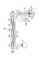
さらに、従来から、2次元画像を虚像光学系により拡大虚像として観察者に観察させるべく表示する虚像表示装置として、ホログラム光学素子の中でも、特に、反射型体積ホログラムグレーティングを用いた図23に示すような虚像表示装置200がある。 Further, as a virtual image display device that conventionally displays a two-dimensional image as an enlarged virtual image by a virtual image optical system to be observed by an observer, among hologram optical elements, in particular, as shown in FIG. 23 using a reflective volume hologram grating. There is a virtual
虚像光学装置200は、図23に示すように、画像を表示する画像表示素子211と、画像表示素子211で表示された表示光を入射して、観察者の瞳216へと導く虚像光学系とを備えている。 As shown in FIG. 23, the virtual image
虚像光学系は、コリメート光学系221と、導光板222と、導光板222に設けられた第1の反射型体積ホログラムグレーティング223と、第2の反射型体積ホログラムグレーティング224とを備える。 The virtual image optical system includes a collimating
コリメート光学系221は、画像表示素子211の各画素から射出された光束を入射して、互いに画角の異なる平行光束群とする光学系である。コリメート光学系221から射出された、互いに画角の異なる平行光束群は、それぞれ導光板222に入射される。 The collimating
導光板222は、コリメート光学系221から射出された互いに画角の異なる平行光束群を入射する光入射口222aを一方端部に有し、他方端部に光を射出する光射出口222bを有する光学面222cと、この光学面222cに対向する光学面222dとを主面とする薄型の平行平板な導光板である。 The
導光板222の光学面222dには、光学面222cの光入射口222aと対向する位置に第1の反射型体積ホログラムグレーティング223が設けられ、光学面222cの光射出口222bと対向する位置に第2の反射型体積ホログラムグレーティング224が設けられている。 On the
導光板222の光入射口222aから入射した互いに画角の異なる平行光束群は、上述した第1の反射型体積ホログラムグレーティング223に入射され、それぞれの平行光束群が平行光束群のまま回折反射される。回折反射された平行光束群は、導光板222の光学面222c,222dとの間で全反射を繰り返しながら進行し、上述した第2の反射型体積ホログラムグレーティング224に入射することになる。 The parallel light flux groups having different angles of view incident from the
第2の反射型体積ホログラムグレーティング224に入射した各画角の平行光束群は、回折反射されることで全反射条件からはずれ、導光板222の光射出口222aから射出され、観察者の瞳216に入射する。 The collimated light flux group of each angle of view incident on the second reflective
このように、第2の反射型体積ホログラムグレーティング224は、記録された干渉縞が、第1の反射型体積ホログラムグレーティング223の干渉縞と光学面に直交する面に対して対称な形状となるように、導光板222の光学面222d上に設置されている。したがって、第2の反射型体積ホログラムグレーティング224で反射される平行光束群は、第1の反射型体積ホログラムグレーティング223への入射角と等しい角度で反射されることになるため、表示画像がぼけることなく高い解像度で瞳216へ表示されることになる。 As described above, the second reflection type
しかしながら、虚像表示装置200は、図23に示すように、画像表示素子211からコリメートされた全ての平行光束が第2の反射型体積ホログラムグレーティング224により回折反射されて内部全反射平行光束として導光板内を伝播するための条件は、導光板媒質の屈折率をnとした場合、回折反射後の各平行光束の光学面222c,222dへの入射角度の範囲がASIN(1/n)度以上90度未満となることである。この光学面222c,222dへの入射角度(以下、内部全反射角度)の範囲は、第2の反射型体積ホログラムグレーティング224により回折反射された平行光束が観察者の瞳216に入射する角度範囲を決めるものであり、すなわち観察者が観察する虚像の画角を決めるものである。よって、この虚像光学装置200では、虚像の画角が導光板媒質の屈折率nによって制約されるという問題がある。 However, in the virtual
さらに図23において、導光板222内の媒質屈折率nを例えば1.5としたとき、平行光束の内部全反射角度の範囲は41.2度以上90度未満となる。これは、第2の反射型体積ホログラムグレーティング224により回折反射されて観察者に観察される虚像の画角が最大で±14度程度になるということを示している。ここで現実的な内部全反射の条件を鑑みて、例えば虚像が±10度程度になるように赤、緑、青の各色の干渉縞を記録した反射型体積ホログラムグレーティングを積層もしくは多重したものを第1及び第2の反射型体積ホログラムグレーティング223,224としてそれぞれ使用したとする。この場合、平行光束の内部全反射角度範囲は約45度以上70度以下となる。 Furthermore, in FIG. 23, when the medium refractive index n in the
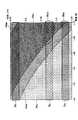
このとき、図24乃至図26に各色の干渉縞を記録した第2の反射型体積ホログラムグレーティングの媒質内入射角度と波長による回折効率の関係を示す。これを見ると第1の反射型体積ホログラムグレーティング223により導光板222内に回折反射されたそれぞれ赤色、緑色、青色の略同一波長帯域の平行光束の一部が、第2の反射型体積ホログラムグレーティング224の内部の、本来対応する干渉縞とは異なる干渉縞、すなわち、本来の干渉縞とは異なるピッチを有する干渉縞にて回折効率を有していることがわかる。尚、ここで、この赤色、緑色、青色の略同一波長帯域の平行光束は、LED光源を想定している。 At this time, FIGS. 24 to 26 show the relationship between the incident angle in the medium and the diffraction efficiency depending on the wavelength of the second reflective volume hologram grating in which the interference fringes of the respective colors are recorded. As can be seen, some of the parallel luminous fluxes of substantially the same wavelength band of red, green, and blue that are diffracted and reflected in the
すなわち、図24では、第2の反射型体積ホログラムグレーティング224の青色に対応した第1の干渉縞224Bによる媒質内入射角度と波長とによる回折効率の分布を示す図である。すなわち、図24中において、領域ABHは、高い回折効率を有する範囲を示し、領域ABLは、ほとんど回折効率を有さない範囲を示し、領域ABMは、中間の回折効率であり影響を及ぼさない程度の回折効率を有する範囲を示すものである。また、領域BBは、青色の波長帯域を示し、領域BGは、緑色の波長帯域を示し、領域BRは、赤色の波長帯域を示すものである。That is, FIG. 24 is a diagram showing the distribution of diffraction efficiency depending on the incident angle in the medium and the wavelength by the first interference fringe 224B corresponding to the blue color of the second reflective
図24において、領域BBのほとんどの部分が領域ABHに含まれており、この第1の干渉縞224Bが青色の波長帯域を有する光束に対し、高い回折効率を有していることを示している。一方で、図24において、領域BGと領域ABHとの重なる領域BGHが存在してしまい、この領域BGHでは、この第1の干渉縞224Bが緑色の波長帯域を有する光束を回折してしまうことになる。すなわち、第1の干渉縞224Bは、緑色の波長帯域を有する光束が約−45〜約−60度の範囲で入射されたときに、回折反射してしまうことになる。In FIG. 24, most of the region BB is included in the region ABH , and this first interference fringe 224B has a high diffraction efficiency for a light beam having a blue wavelength band. ing. On the other hand, in FIG. 24, there is a region BGH where the region BG and the region ABH overlap, and in this region BGH , the first interference fringe 224B diffracts a light beam having a green wavelength band. It will end up. That is, the first interference fringe 224B is diffracted and reflected when a light beam having a green wavelength band is incident in a range of about −45 to about −60 degrees.
また、図25では、第2の反射型体積ホログラムグレーティング224の緑色に対応した第2の干渉縞224Gによる媒質内入射角度と波長とによる回折効率の分布を示す図である。すなわち、図25中において、領域AGHは、高い回折効率を有する範囲を示し、領域AGLは、ほとんど回折効率を有さない範囲を示し、領域AGMは、中間の回折効率であり影響を及ぼさない程度の回折効率を有する範囲を示すものである。また、領域BBは、青色の波長帯域を示し、領域BGは、緑色の波長帯域を示し、領域BRは、赤色の波長帯域を示すものである。FIG. 25 is a diagram showing the distribution of diffraction efficiency depending on the incident angle and wavelength in the medium by the second interference fringe 224G corresponding to the green color of the second reflective
図25において、領域BGのほとんどの部分が領域AGHに含まれており、この第2の干渉縞224Gが緑色の波長帯域を有する光束に対し、高い回折効率を有していることを示している。一方で、図25において、領域BBと領域AGHとの重なる領域BBHが存在してしまい、この領域BBHでは、この第2の干渉縞224Gが青色の波長帯域を有する光束を回折してしまうことになる。すなわち、第2の干渉縞224Gは、青色の波長帯域を有する光束が約−58〜約−70度の範囲で入射されたときに、回折反射してしまうことになる。FIG. 25 shows that most of the region BG is included in the region AGH , and this second interference fringe 224G has a high diffraction efficiency for a light beam having a green wavelength band. ing. On the other hand, in FIG. 25, there is a region BBH where the region BB and the region AGH overlap, and in this region BBH , the second interference fringe 224G diffracts a light beam having a blue wavelength band. It will end up. That is, the second interference fringe 224G is diffracted and reflected when a light beam having a blue wavelength band is incident in a range of about −58 to about −70 degrees.
また、図26では、第2の反射型体積ホログラムグレーティング224の赤色に対応した第3の干渉縞224Rによる媒質内入射角度と波長とによる回折効率の分布を示す図である。すなわち、図26中において、領域ARHは、高い回折効率を有する範囲を示し、領域ARLは、ほとんど回折効率を有さない範囲を示し、領域ARMは、中間の回折効率であり影響を及ぼさない程度の回折効率を有する範囲を示すものである。また、領域BBは、青色の波長帯域を示し、領域BGは、緑色の波長帯域を示し、領域BRは、赤色の波長帯域を示すものである。FIG. 26 is a diagram showing the distribution of diffraction efficiency depending on the incident angle and wavelength in the medium by the third interference fringe 224R corresponding to the red color of the second reflective volume hologram grating 224. That is, in FIG. 26, a region ARH indicates a range having high diffraction efficiency, a region ARL indicates a range having little diffraction efficiency, and a region ARM is an intermediate diffraction efficiency and has an influence. This indicates a range having a diffraction efficiency that does not reach. The area BB indicates a blue wavelength band, region BG indicates the green wavelength band, region BR shows a red wavelength band.
図26において、領域BRのほとんどの部分が領域ARHに含まれており、この第3の干渉縞224Rが赤色の波長帯域を有する光束に対し、高い回折効率を有していることを示している。一方で、図26において、領域BGと領域ARHとの重なる領域BGHが存在してしまい、この領域BGHでは、この第3の干渉縞224Rが緑色の波長帯域を有する光束を回折してしまうことになる。すなわち、第3の干渉縞224Rは、緑色の波長帯域を有する光束が約−63〜約−70度の範囲で入射されたときに、回折反射してしまうことになる。さらに、図26において、領域BBと領域ARHとの重なる領域BBHが存在してしまい、この領域BBHでは、この第3の干渉縞224Rが青色の波長帯域を有する光束を回折してしまうことになる。すなわち、第3の干渉縞224Rは、青色の波長帯域を有する光束が約−68〜約−70度の範囲で入射されたときに、回折反射してしまうことになる。In Figure 26, it included in the most part the area ARH area BR, indicates that the third interference fringe 224R is to the light beam having a wavelength band of red, and has a high diffraction efficiency ing. On the other hand, in FIG. 26, there is a region BGH in which the region BG and the region ARH overlap, and in this region BGH , the third interference fringe 224R diffracts a light beam having a green wavelength band. It will end up. That is, the third interference fringe 224R is diffracted and reflected when a light beam having a green wavelength band is incident in a range of about −63 to about −70 degrees. Further, in FIG. 26, there is a region BBH where the region BB and the region ARH overlap. In this region BBH , the third interference fringe 224R diffracts a light beam having a blue wavelength band. Will end up. That is, the third interference fringe 224R is diffracted and reflected when a light beam having a blue wavelength band is incident in a range of about −68 to about −70 degrees.
これは、例えば、導光板222内を内部全反射する平行光束の一部が、第1の反射型体積ホログラムグレーティング223と異なるグレーティングピッチをもつ第2の反射型体積ホログラムグレーティング224により回折反射されることを示している。 This is because, for example, a part of the parallel light beam that is totally internally reflected in the
これは、図27に主要光線のみで示すように、本来L1のように青色用の第2の反射型体積ホログラムグレーティングの干渉縞224Bによって回折反射される平行光束の一部が、L2のように緑色用の第2の反射型体積ホログラムグレーティングの干渉縞224Gによって回折反射され、光束の一部が所望の入射角度から外れた角度で観察者の瞳に入射し、ゴーストが発生することを示している。 As shown in FIG. 27 with only the principal rays, a part of the parallel light beam diffracted and reflected by the interference fringes 224B of the second reflective volume hologram grating for blue as originally shown in L1 is as shown in L2. It is diffracted and reflected by the interference fringes 224G of the second reflection type volume hologram grating for green, and a part of the light beam is incident on the observer's pupil at an angle deviating from a desired incident angle, and a ghost is generated. Yes.
また、光源を単色に制限した場合であっても、前述のように導光板を1枚しか用いない場合には、表示できる最大画角は±14程度に制約され、これ以上の広画角化は不可能である。 Even when the light source is limited to a single color, if only one light guide plate is used as described above, the maximum field angle that can be displayed is limited to about ± 14, and a wider field angle than this is possible. Is impossible.
このように、虚像表示装置200では、赤色、緑色、青色の各色の干渉縞が記録された第2の反射型体積ホログラムグレーティング224が、それぞれ対応する平行光束とは異なる他色の平行光束を回折反射してゴーストを発生させてしまうという問題がある。この問題を回避するためには、第2の反射型体積ホログラムグレーティング224に記録されたが各色の干渉縞が他色の平行光束を回折反射しない程度まで導光板222内の内部全反射角度の範囲を狭めなくてはならず、結果的に観察者が観察する虚像の画角を狭めなければならないことを意味している。よって本手法で広画角を実現するのは困難であった。 As described above, in the virtual
本発明の目的は、ゴーストの発生を低減し、広画角化を実現する光学装置及び虚像表示装置を提供することにある。 An object of the present invention is to provide an optical device and a virtual image display device that reduce the occurrence of ghosts and realize a wide angle of view.
上述の目的を達成するために、本発明に係る光学装置は、互いに進行方位の異なる平行光束群が入射し内部を全反射により伝播した後射出するよう構成された複数の導光板が、前記導光板よりも屈折率の低い媒質を介して積層されてなる光学装置であって、前記複数の導光板は、それぞれ、前記平行光束群の入射領域にて前記平行光束群を平行光束群のまま前記導光板内で内部全反射条件を満たすよう回折反射する第1の反射型体積ホログラムグレーティングと、前記平行光束群の射出領域にて前記平行光束群を平行光束群のまま前記導光板より射出するよう回折反射する第2の反射型体積ホログラムグレーティングとを有し、前記複数の導光板の第1の反射型体積ホログラムグレーティング及び第2の反射型体積ホログラムグレーティングのうち少なくとも第1の反射型体積ホログラムグレーティングは、全て同一光路上に存在するとともに、前記複数の導光板の第1の反射型体積ホログラムグレーティングは、前記平行光群の一部を順次回折し、前記複数の導光板内の入射領域から射出領域にかけて全反射を繰り返しながら伝播する互いに進行方位の異なる平行光束群は、少なくともその一部が前記進行方位の違いによって全反射回数が互いに異なる。 In order to achieve the above-described object, an optical device according to the present invention includes a plurality of light guide plates configured so that parallel light flux groups having different traveling directions enter each other, propagate through the interior by total reflection, and then exit. An optical device that is stacked through a medium having a refractive index lower than that of an optical plate, wherein each of the plurality of light guide plates maintains the parallel light beam group as a parallel light beam group in the incident region of the parallel light beam group. A first reflective volume hologram grating that diffracts and reflects so as to satisfy the internal total reflection condition in the light guide plate, and the parallel light beam group is emitted from the light guide plate as a parallel light beam group in the emission region of the parallel light beam group. A first reflection type volume hologram grating and a second reflection type volume hologram grating of the plurality of light guide plates. Among them, at least the first reflective volume hologram grating is present on the same optical path, and the first reflective volume hologram grating of the plurality of light guide plates sequentially diffracts a part of the parallel light group, The parallel light flux groups having different traveling directions and propagating while repeating total reflection from the incident region to the emitting region in the plurality of light guide plates have at least a part of the total number of reflections different depending on the traveling direction.
また、上述の目的を達成するために、本発明に係る虚像表示装置は、光源と、前記光源から射出された光束を平行光とするコリメート光学系と、前記平行光を走査する走査光学系と、前記走査光学系にて互いに進行方位の異なる平行光束となされた平行光束群が入射し内部を全反射により伝播した後、観察者の瞳に向けて射出するよう構成された複数の導光板が、前記導光板よりも屈折率の低い媒質を介して積層されてなる光学装置とからなる画像表示装置であって、前記複数の導光板は、それぞれ、前記平行光束群の入射領域にて前記平行光束群を平行光束群のまま前記導光板内で内部全反射条件を満たす角度で回折反射する第1の反射型体積ホログラムグレーティングと、前記導光板内を内部全反射にて伝播する平行光束群の射出領域にて前記平行光束群を平行光束群のまま前記導光板より射出する角度で回折反射する第2の反射型体積ホログラムグレーティングとをそれぞれ前記導光板の全反射面と平行にその内部に有し、前記複数の導光板の第1の反射型体積ホログラムグレーティング及び第2の反射型体積ホログラムグレーティングのうち少なくとも第1の反射型体積ホログラムグレーティングは、全て同一光路上に存在するとともに、前記複数の導光板の第1の反射型体積ホログラムグレーティングは、前記平行光群の一部を順次回折し、前記複数の導光板内で全反射を繰り返しながら伝播する互いに進行方位の異なる平行光束群は、少なくともその一部が前記進行方位の違いによって全反射回数が互いに異なる。 In order to achieve the above object, a virtual image display device according to the present invention includes a light source, a collimating optical system that makes a light beam emitted from the light source parallel light, and a scanning optical system that scans the parallel light. And a plurality of light guide plates configured to be emitted toward the observer's pupil after the parallel light flux group which has been made into parallel light fluxes having different traveling directions in the scanning optical system is incident and propagated through total reflection. , An image display device comprising an optical device stacked via a medium having a lower refractive index than the light guide plate, wherein the plurality of light guide plates are each parallel to each other in the incident region of the parallel light beam group. A first reflection-type volume hologram grating that diffracts and reflects the light beam group at an angle satisfying the internal total reflection condition in the light guide plate while maintaining the parallel light beam group; and a parallel light beam group that propagates in the light guide plate by total internal reflection. In the injection area A plurality of second reflective volume hologram gratings that diffract and reflect the parallel light beam group at an angle at which the parallel light beam group is emitted from the light guide plate in parallel with the total reflection surface of the light guide plate; Of the first reflective volume hologram grating and the second reflective volume hologram grating of the light guide plate, at least the first reflective volume hologram grating is present on the same optical path, and The reflection type volume hologram grating of 1 diffracts a part of the parallel light group sequentially, and at least a part of the parallel light flux groups having different traveling directions and propagating while repeating total reflection in the plurality of light guide plates The total number of reflections is different depending on the traveling direction.
また、上述の目的を達成するために、本発明に係る虚像表示装置は、画像表示素子と、前記画像表示素子の各画素から射出された光束を互いに進行方位の異なる平行光束群にするコリメート光学系と、前記平行光束群が入射し内部を全反射により伝播した後、観察者の瞳に向けて射出するよう構成された複数の導光板が、前記導光板よりも屈折率の低い媒質を介して積層されてなる光学装置とからなる画像表示装置であって、前記複数の導光板は、それぞれ、前記平行光束群の入射領域にて前記平行光束群を平行光束群のまま前記導光板内で内部全反射条件を満たすよう回折反射する第1の反射型体積ホログラムグレーティングと、前記平行光束群の射出領域にて前記平行光束群を平行光束群のまま前記導光板より射出するよう回折反射する第2の反射型体積ホログラムグレーティングとをそれぞれ前記導光板の全反射面と平行にその内部に有し、前記複数の導光板の第1の反射型体積ホログラムグレーティング及び第2の反射型体積ホログラムグレーティングのうち少なくとも第1の反射型体積ホログラムグレーティングは、全て同一光路上に存在するとともに、前記複数の導光板の第1の反射型体積ホログラムグレーティングは、前記平行光群の一部を順次回折し、前記複数の導光板内の入射領域から射出領域にかけて全反射を繰り返しながら伝播する互いに進行方位の異なる平行光束群は、少なくともその一部が前記進行方位の違いによって全反射回数が互いに異なる。 In order to achieve the above-described object, the virtual image display device according to the present invention includes an image display element and collimating optics that converts light beams emitted from each pixel of the image display element into parallel light beam groups having different traveling directions. And a plurality of light guide plates configured to be emitted toward the observer's pupil after the parallel light flux group is incident and propagated by total internal reflection through a medium having a refractive index lower than that of the light guide plate. Each of the plurality of light guide plates within the light guide plate while the parallel light beam group remains as the parallel light beam group in the incident region of the parallel light beam group. A first reflective volume hologram grating that diffracts and reflects so as to satisfy the internal total reflection condition, and diffracted and reflected so that the parallel light beam group is emitted from the light guide plate as a parallel light beam group in the emission region of the parallel light beam group. Two reflection type volume hologram gratings in parallel with the total reflection surface of the light guide plate, and the first reflection type volume hologram grating and the second reflection type volume hologram grating of the plurality of light guide plates. Among them, at least the first reflective volume hologram grating is present on the same optical path, and the first reflective volume hologram grating of the plurality of light guide plates sequentially diffracts a part of the parallel light group, The parallel light flux groups having different traveling directions and propagating while repeating total reflection from the incident region to the emitting region in the plurality of light guide plates have at least a part of the total number of reflections different depending on the traveling direction.
本発明に係る光学装置及び虚像表示装置は、それぞれ第1及び第2の反射型体積ホログラムグレーティングが配置された複数の導光板を、これらの導光板よりも屈折率の低い媒質を介して積層することにより、第1の反射型体積ホログラムグレーティングへの入射角度及び第2の反射型体積ホログラムグレーティングからの回折反射角度の幅を広げ、広画角化を実現する。 The optical device and the virtual image display device according to the present invention are configured by laminating a plurality of light guide plates on which the first and second reflective volume hologram gratings are disposed via a medium having a lower refractive index than these light guide plates. As a result, the angle of incidence on the first reflection type volume hologram grating and the width of the diffraction reflection angle from the second reflection type volume hologram grating are widened to realize a wide angle of view.
また、本発明に係る光学装置及び虚像表示装置は、それぞれの第1の反射型体積ホログラムグレーティングにより回折反射され各導光板内を内部全反射により伝播する複数の略同一波長帯域の平行光束が、それぞれの第2の反射型体積ホログラムグレーティングの対応しない部分で回折反射されることを防止することができ、虚像をカラーで観察するときのゴーストを低減することができる。 Further, in the optical device and the virtual image display device according to the present invention, a plurality of parallel light beams in substantially the same wavelength band, which are diffracted and reflected by the respective first reflection type volume hologram gratings and propagate in each light guide plate by total internal reflection, It is possible to prevent diffraction reflection at a portion of each second reflective volume hologram grating that does not correspond, and to reduce a ghost when a virtual image is observed in color.
以下、本発明を適用した光学装置及び虚像表示装置について、図面を参照して説明する。 Hereinafter, an optical device and a virtual image display device to which the present invention is applied will be described with reference to the drawings.
{第1の実施の形態}
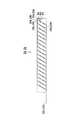
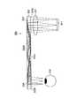
図1に、第1の実施の形態として示す虚像表示装置10を示す。虚像表示装置10は、各画素から光束を出射して画像を表示する画像表示素子11と、画像表示素子11から出射された光束である表示光を入射して、観察者の瞳16へと導く虚像光学系とを備えている。{First embodiment}
FIG. 1 shows a virtual
画像表示素子11は、例えば、有機EL(Electro Luminescence)ディスプレイ、無機ELディスプレイや、液晶ディスプレイ(LCD:Liquid Crystal Display)などである。この画像表示素子11は、後述するコリメータ光学系21により平行とされる平行光を走査する走査光学系として機能する。 The
尚、ここでは、画像表示素子11の各画素から表示光を出射するように構成したが、これに限られるものではなく、例えば、照明光を出射する照明光源と、この照明光源から出射された照明光を空間変調する透過型の液晶ディスプレイ等の空間変調素子とを設け、この空間変調素子が入射された照明光を画素毎に空間変調することで、後述する虚像光学系の導光板の入射面の面内において、平行光を走査する走査光学系として機能させるように構成してもよい。 Here, the display light is emitted from each pixel of the
虚像光学系は、コリメート光学系21と、第1の導光板22と、第2の導光板23と、第1の導光板22に設けられた第1の反射型体積ホログラムグレーティング25及び第2の反射型体積ホログラムグレーティング26と、第2の導光板23に設けられた第3の反射型体積ホログラムグレーティング27及び第4の反射型体積ホログラムグレーティング28とを備える。 The virtual image optical system includes a collimating optical system 21, a first
コリメート光学系21は、画像表示素子11の各画素から射出された光束が入射されて、互いに画角の異なる平行光束群を出射させる光学系である。コリメート光学系21から射出された、互いに画角の異なる平行光束群は、それぞれ第1の導光板22に入射される。 The collimating optical system 21 is an optical system that receives a light beam emitted from each pixel of the
第1及び第2の導光板22,23は、この第1及び第2の導光板22,23よりも屈折率の低い媒質として空気層24を介して積層されてなり、画像表示素子11及びコリメート光学系21により、互いに進行方位の異なる平行光束となされた平行光束群が入射され、内部を全反射により伝播した後、観察者の瞳に向けて射出するように構成されている。尚、ここでは、第1及び第2の導光板22,23よりも屈折率の低い媒質として空気層24を用いたが、これに限られるものではない。また、第1及び第2の導光板22,23は、その全反射面が略平行となるように配置されている。 The first and second
第1の導光板22は、コリメート光学系21から射出された平行光束群を入射する光入射口22aを一方端部に有し、他方端部に光を射出する光射出口22bを有する第1の光学面22cと、この第1の光学面22cに対向する第2の光学面22dとを主面とする薄型の平行平板な導光板である。 The first
第1の導光板22の第2の光学面22dには、第1の光学面22cの光入射口22aと対向する位置に第1の反射型体積ホログラムグレーティング25が設けられ、第1の光学面22cの光射出口22bと対向する位置に第2の反射型体積ホログラムグレーティング26が設けられている。 A first reflective volume hologram grating 25 is provided on the second
この第1及び第2の反射型体積ホログラムグレーティング25,26は、第1の導光板22の全反射面と平行に配置されている。第1の反射型体積ホログラムグレーティング25は、平行光束群の入射領域にて平行光束群を平行光束群のまま第1の導光板22内で内部全反射条件を満たす角度で回折反射させる。第2の反射型体積ホログラムグレーティング26は、第1の導光板22内を内部全反射にて伝播する平行光束群の射出領域にて平行光束群を平行光束群のまま第1の導光板22より射出させる角度で回折反射させる。 The first and second reflective
第2の導光板23は、コリメート光学系21から射出された平行光束群を入射する光入射口23aを一方端部に有し、他方端部に光を射出する光射出口23bを有する第1の光学面23cと、この第3の光学面23cに対向する第4の光学面23dとを主面とする薄型の平行平板な導光板である。 The second
第2の導光板23の第4の光学面23dには、第3の光学面23cの光入射口23aと対向する位置に第3の反射型体積ホログラムグレーティング27が設けられ、第3の光学面23cの光射出口23bと対向する位置に第4の反射型体積ホログラムグレーティング28が設けられている。 The fourth
この第3及び第4の反射型体積ホログラムグレーティング27,28は、第2の導光板23の全反射面と平行に配置されている。第3の反射型体積ホログラムグレーティング27は、平行光束群の入射領域にて平行光束群を平行光束群のまま第2の導光板23内で内部全反射条件を満たす角度で回折反射させる。第4の反射型体積ホログラムグレーティング28は、第2の導光板23内を内部全反射にて伝播する平行光束群の射出領域にて平行光束群を平行光束群のまま第2の導光板23より射出させる角度で回折反射させる。 The third and fourth reflective
第1及び第2の導光板22,23の第1乃至第4の反射型体積ホログラムグレーティング25,26,27,28のうち少なくとも第1及び第3の反射型体積ホログラムグレーティング25,27は、コリメート光学系21から出射される光束の同一光路上に存在するように配置されている。尚、ここでは、第2及び第4の反射型体積ホログラムグレーティング26,28も、瞳16に入射する光束の同一光路上に存在するように配置されている。 Of the first to fourth reflective
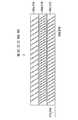
ここで、図2及び図3に、干渉縞が記録された第1の反射型体積ホログラムグレーティング25、第2の反射型体積ホログラムグレーティング26の断面図をそれぞれ示す。 Here, FIGS. 2 and 3 are sectional views of the first reflective volume hologram grating 25 and the second reflective volume hologram grating 26 on which interference fringes are recorded, respectively.
図2及び図3に示すように、第1及び第2の反射型体積ホログラムグレーティング25,26には、干渉縞の傾きであるスラント角が異なる3種類の干渉縞が、ホログラム表面25S,26Sにおいて、それぞれ同一ピッチとなるように多重して記録されている。第1及び第2の反射型体積ホログラムグレーティング25,26は、回折受容波長帯域が20nm程度の単色用のホログラムグレーティングであり、上述したスラント角がそれぞれ異なる3種類の干渉縞を記録することで、回折受容角を広げている。 As shown in FIGS. 2 and 3, the first and second reflective
図2に示すように第1の反射型体積ホログラムグレーティング25には、干渉縞25a,25b,25cがスラント角θa,θb,θcで、それぞれ同一ピッチ、つまり位置に関わらず均等なピッチで複数記録されている。図3に示す第2の反射型体積ホログラムグレーティング26も同様に、干渉縞26a,26b,26cがスラント角θa,θb,θcでそれぞれ同一ピッチにて複数記録されている。したがって、第1及び第2の反射型体積ホログラムグレーティング25,26は、それぞれの干渉縞が第2の光学面22dと垂直な平面に対して対称となるように、第1の導光板22の第2の光学面22d上に配置されていることになる。 As shown in FIG. 2, in the first reflective volume hologram grating 25,
第1の導光板22の光入射口22aから入射した互いに画角の異なる平行光束群は、上述した第1の反射型体積ホログラムグレーティング25に入射され、それぞれの平行光束群が平行光束群のまま回折反射される。回折反射された平行光束群は、第1の導光板22の第1及び第2の光学面22c,22dの間で全反射を繰り返しながら進行し、上述した第2の反射型体積ホログラムグレーティング26に入射することになる。 The parallel light flux groups having different angles of view incident from the
また、第1の導光板22の第1の反射型体積ホログラムグレーティング25は、第1の導光板22に入射した平行光束のうち瞳16側とは逆側に傾斜した入射角度で入射する平行光束を平行光のまま回折反射させるとともに、第1の導光板22に入射した平行光束のうち瞳16側に傾斜した入射角度で入射する平行光束に対しては小さな回折効率しか有さず、空気層24及び第2の導光板23側に透過させる。 In addition, the first reflective volume hologram grating 25 of the first
第1の導光板22の第2の反射型体積ホログラムグレーティング26は、第1の反射型体積ホログラムグレーティング26で回折反射され第1の導光板22の内部で第1の光学面22cと第2の光学面22dとの間で全反射を繰り返して入射した平行光束を回折反射により全反射条件からはずして光射出口22bから観察者の瞳16側に射出するとともに、第2の導光板23の第4の反射型体積ホログラムグレーティング28により回折反射されて光射出口23bから射出された平行光束に対して小さな回折効率しか有さず、光射出口22bから観察者の瞳16側に射出する。 The second reflection type volume hologram grating 26 of the first
第1の導光板22の長手方向の長さ及び第1の光学面22cと第2の光学面22dとの間の厚みは、このときに内部を全反射しながら進行する互いに画角の異なる平行光束群が、各画角によって、第2の反射型体積ホログラムグレーティング26に到達するまでの全反射回数に違いがでるような光路長となるように、薄型化され、長手方向の長さも十分な長さとなるように設計されている。 The length of the first
具体的には、第1の導光板22に入射する平行光束群のうち、第2の反射型体積ホログラムグレーティング26側へ傾きながら入射する平行光束、つまり入射角が大きな平行光束の反射回数は、それとは、逆に第2の反射型体積ホログラムグレーティング26側へあまり傾かずに入射する平行光束、つまり入射角が小さな平行光束の反射回数と比較して少なくなる。これは、第1の導光板22に入射した平行光束群は、それぞれ画角の異なる平行光束となって入射されるためである。つまり、第1の反射型体積ホログラムグレーティング25への入射角度も異なることから、それぞれ異なる回折角で射出されることで、各平行光束の全反射角も異なっているため、第1の導光板22を、薄型化し、長手方向の長さを十分確保することで、全反射する回数に違いが顕著にでることになる。 Specifically, the number of reflections of the parallel luminous flux incident on the first
第2の反射型体積ホログラムグレーティング26に入射した各画角の平行光束群は、回折反射されることで全反射条件からはずれ、第1の導光板22の光射出口22bから射出され、観察者の瞳16に入射する。 The parallel light flux group having each angle of view incident on the second reflection type volume hologram grating 26 is diffracted and reflected to deviate from the total reflection condition, and is emitted from the
このように、第2の反射型体積ホログラムグレーティング26は、記録された干渉縞が、第1の反射型体積ホログラムグレーティング25の干渉縞を第1の導光板22の第1及び第2の光学面22c,22dに直交する面に対して対称形状となるように、第1の導光板22の第2の光学面22d上に設置されている。すなわち、第1及び第2の体積ホログラムグレーティング25,26は、その中間に対称面を有している。 As described above, the second reflection type volume hologram grating 26 has the recorded interference fringes as the interference fringes of the first reflection type volume hologram grating 25, and the first and second optical surfaces of the first
したがって、第2の反射型体積ホログラムグレーティング26で反射される平行光束群は、第1の反射型体積ホログラムグレーティング25への入射角と等しい角度で反射されることになるため、表示画像がぼけることなく高い解像度で瞳16へ表示されることになる。 Accordingly, the parallel light beam group reflected by the second reflective volume hologram grating 26 is reflected at an angle equal to the incident angle to the first reflective volume hologram grating 25, and thus the display image is blurred. It is displayed on the
次に、図2及び図3を用いた第2の導光板23の第3及び第4の反射型体積ホログラムグレーティング27,28について説明する。 Next, the third and fourth reflective
図2及び図3に示すように、第3及び第4の反射型体積ホログラムグレーティング27,28には、干渉縞の傾きであるスラント角が異なる3種類の干渉縞が、ホログラム表面27S,28Sにおいて、それぞれ同一ピッチとなるように多重して記録されている。第3及び第4の反射型体積ホログラムグレーティング27,28は、回折受容波長帯域が20nm程度の単色用のホログラムグレーティングであり、上述したスラント角がそれぞれ異なる3種類の干渉縞を記録することで、回折受容角を広げている。 As shown in FIGS. 2 and 3, the third and fourth reflective
図2に示すように第3の反射型体積ホログラムグレーティング27には、干渉縞27a,27b,27cがスラント角θa,θb,θcで、それぞれ同一ピッチ、つまり位置に関わらず均等なピッチで複数記録されている。図3に示す第4の反射型体積ホログラムグレーティング28も同様に、干渉縞28a,28b,28cがスラント角θa,θb,θcでそれぞれ同一ピッチにて複数記録されている。したがって、第3及び第4の反射型体積ホログラムグレーティング27,28は、それぞれの干渉縞が第4の光学面23dと垂直な平面に対して対称となるように、第2の導光板23の第4の光学面23d上に配置されていることになる。 As shown in FIG. 2, in the third reflective volume hologram grating 27,
第2の導光板23の光入射口23aから入射した互いに画角の異なる平行光束群は、上述した第3の反射型体積ホログラムグレーティング27に入射され、それぞれの平行光束群が平行光束群のまま回折反射される。回折反射された平行光束群は、第2の導光板23の第3及び第4の光学面23c,23dとの間で全反射を繰り返しながら進行し、上述した第4の反射型体積ホログラムグレーティング28に入射することになる。 The parallel light flux groups having different angles of view incident from the
また、第2の導光板23の第3の反射型体積ホログラムグレーティング27は、第1の導光板22の第1の反射型体積ホログラムグレーティング25を透過された瞳16側に傾斜した入射角度で入射した平行光束を、平行光のまま回折反射する。 Further, the third reflective volume hologram grating 27 of the second
第2の導光板23の第4の反射型体積ホログラムグレーティング28は、第3の反射型体積ホログラムグレーティング27で回折反射され第2の導光板23の内部で第3の光学面23cと第4の光学面23dとの間で全反射を繰り返して入射した平行光束を回折反射により全反射条件からはずして光射出口23bから第1の導光板22の第2の反射型体積ホログラムグレーティング26側に射出する。 The fourth reflection type volume hologram grating 28 of the second
第2の導光板23の長手方向の長さ及び第3の光学面23cと第4の光学面23dとの間の厚みは、このときに内部を全反射しながら進行する互いに画角の異なる平行光束群が、各画角によって、第4の反射型体積ホログラムグレーティング28に到達するまでの全反射回数に違いがでるような光路長となるように、薄型化され、長手方向の長さも十分な長さとなるように設計されている。 The length of the second
具体的には、第2の導光板23に入射する平行光束群のうち、第4の反射型体積ホログラムグレーティング28側へ傾きながら入射する平行光束、つまり入射角が大きな平行光束の反射回数は、それとは、逆に第4の反射型体積ホログラムグレーティング28側へあまり傾かずに入射する平行光束、つまり入射角が小さな平行光束の反射回数と比較して少なくなる。これは、第2の導光板23に入射した平行光束群は、それぞれ画角の異なる平行光束となって入射されるためである。つまり、第3の反射型体積ホログラムグレーティング27への入射角度も異なることから、それぞれ異なる回折角で射出されることで、各平行光束の全反射角も異なっているため、第2の導光板23を、薄型化し、長手方向の長さを十分確保することで、全反射する回数に違いが顕著にでることになる。 Specifically, among the parallel light flux group incident on the second
第4の反射型体積ホログラムグレーティング28に入射した各画角の平行光束群は、回折反射されることで全反射条件からはずれ、第2の導光板23の光射出口23bから射出され、第1の導光板22に入射する。 The collimated light flux group having each angle of view incident on the fourth reflective volume hologram grating 28 is diffracted and reflected to deviate from the total reflection condition, and is emitted from the
このように、第4の反射型体積ホログラムグレーティング28は、記録された干渉縞が、第3の反射型体積ホログラムグレーティング27の干渉縞を第2の導光板23の第3及び第4の光学面23c,23dに直交する面に対して対称形状となるように、第2の導光板23の第4の光学面23d上に設置されている。すなわち、第3及び第4の体積ホログラムグレーティング27,28は、その中間に対称面を有している。 As described above, the fourth reflection type volume hologram grating 28 has the recorded interference fringes as the interference fringes of the third reflection type volume hologram grating 27 and the third and fourth optical surfaces of the second
したがって、第4の反射型体積ホログラムグレーティング28で反射される平行光束群は、第3の反射型体積ホログラムグレーティング27への入射角と等しい角度で反射されることになるため、表示画像がぼけることなく高い解像度で瞳16へ表示されることになる。 Accordingly, the parallel light beam group reflected by the fourth reflective volume hologram grating 28 is reflected at an angle equal to the incident angle to the third reflective volume hologram grating 27, and thus the display image is blurred. It is displayed on the
この虚像表示装置10は、レンズ効果のない第1乃至第4の反射型体積ホログラムグレーティング25,26,27,28を備えることで、単色偏心収差、回折色収差を排除低減することができる。 The virtual
以上のように構成された虚像表示装置10において、画像表示素子11から出射された光束の光路について説明する。 In the virtual
図1に示すように、画像表示素子11から出射された単色の表示光は、コリメート光学系21を通して画角の異なる平行光とされた後、光入射口22aから第1の導光板22に入射する。 As shown in FIG. 1, the monochromatic display light emitted from the
第1の導光板22に入射した平行光束のうち瞳16側とは逆側に傾斜した入射角度で入射する平行光束は、第1の反射型体積ホログラムグレーティング25に入射し、平行光のまま回折反射され、第1の導光板22の内部で第1の光学面22cと第2の光学面22dとの間で全反射を繰り返しながら、第1の導光板22の他端側に設けられた第2の反射型体積ホログラムグレーティング26に向けて進行する。 Among the parallel light beams incident on the first
第2の反射型体積ホログラムグレーティング26に入射した平行光は、回折反射により全反射条件からはずれて、第1の導光板22の光射出口22bから射出され、観察者の瞳16に入射する。 The parallel light incident on the second reflective volume hologram grating 26 deviates from the total reflection condition due to diffraction reflection, is emitted from the
一方、第1の導光板22に入射した平行光束のうち瞳16側に傾斜した入射角度で入射する平行光束は、第1の導光板22を経て、第1の反射型体積ホログラムグレーティング25では小さな回折効率しか有さず、その大部分が第1の反射型体積ホログラムグレーティング25を透過し、第2の光学面22d側から射出され、空気層24を通過して、光入射口23aから第2の導光板23に入射する。 On the other hand, among the parallel light beams incident on the first
第2の導光板23に入射した平行光束は、第3の反射型体積ホログラムグレーティング27に入射し、平行光のまま回折反射され、第2の導光板23内部で第3の光学面23cと第4の光学面23dとの間で全反射を繰り返しながら、第2の導光板23の他端側に設けられた第4の反射型体積ホログラムグレーティング28に向けて進行する。 The parallel light beam incident on the second
第4の反射型体積ホログラムグレーティング28に入射した平行光は、回折反射により全反射条件からはずれて、第2の導光板23の光射出口23bから射出され、空気層24を通過して第1の導光板22の第2の反射型体積ホログラムグレーティング26に入射する。 The parallel light incident on the fourth reflective volume hologram grating 28 deviates from the total reflection condition by diffraction reflection, is emitted from the
ここで、この第2の反射型体積ホログラムグレーティング26に入射した入射光は、第2の反射型体積ホログラムグレーティング26に対して小さな回折効率しか有さず、その大部分が第2の反射型体積ホログラムグレーティング26を透過し、第1の導光板22を透過して、光射出口22bから射出され、観察者の瞳16に入射する。 Here, the incident light incident on the second reflective volume hologram grating 26 has a small diffraction efficiency with respect to the second reflective volume hologram grating 26, and most of the incident light is the second reflective volume hologram. The light passes through the hologram grating 26, passes through the first
本発明を適用した虚像表示装置10は、第1及び第2の反射型体積ホログラムグレーティング25,26を第1の導光板22に配置し、第3及び第4の反射型体積ホログラムグレーティング27,28を第2の導光板23に配置して、第1及び第2の導光板22,23をこれらの導光板22,23よりも屈折率の低い空気層24を介して積層したことにより、導光板の屈折率に依存する内部全反射条件により制約されていた平行光束の第1の反射型体積ホログラムグレーティングへの入射角度及び第2の反射型体積ホログラムグレーティングからの回折反射角度の範囲を拡大し、広画角化を実現する。 In the virtual
尚、第1の反射型体積ホログラムグレーティング25と、第2の反射型体積ホログラムグレーティング26とは、第1の導光板22の第2の光学面22dに対して各ホログラム面25S,26Sが平行となるように配置されているが、本発明はこれに限定されるものではなく、ホログラム面25S,26Sが、それぞれ第2の光学面22dに対して所定の角度を持つように配置させることもできる。 The first reflective volume hologram grating 25 and the second reflective volume hologram grating 26 have the hologram surfaces 25S and 26S parallel to the second
尚、ここでは、第1及び第2の導光板22,23に設けられた第1乃至第4の体積ホログラムグレーティング25,26,27,28は、略同一波長帯域を回折する干渉縞のホログラム表面の干渉縞ピッチが互いに等しくされているが、これに限られるものではなく、第1及び第2の反射型体積ホログラムグレーティング25,26、並びに、第3及び第4の反射型体積ホログラムグレーティング27,28の少なくとも一対が、略同一波長帯域を回折する干渉縞のホログラム表面の干渉縞ピッチが互いに等しく構成されていればよい。 Here, the first to fourth
また、ここでは、第1及び第2の導光板22,23に設けられた第1乃至第4の体積ホログラムグレーティング25,26,27,28が互いに等しい干渉縞を有しており、第1及び第2の体積ホログラムグレーティング25,26がその中間に対称面を有しており、第3及び第4の体積ホログラムグレーティング27,28がその中間に対称面を有しているように構成したが、これに限られるものではなく、第1及び第2の反射型体積ホログラムグレーティング25,26、並びに、第3及び第4の反射型体積ホログラムグレーティング27,28の少なくとも一対が、互いに等しい干渉縞を有し、かつ本干渉縞が、これらの反射型体積ホログラムグレーティングの中間に対称面を有するよう構成されていればよい。 In addition, here, the first to fourth
また、ここでは、第1乃至第4の反射型体積ホログラムグレーティング25,26,27,28がスラント角の異なる複数の干渉縞を多重化して構成したが、これに限られるものではなく、平行光束群を平行光束群のまま導光板内で内部全反射条件を満たすよう回折反射する入射側に設けられる第1及び第3の反射型体積ホログラムグレーティングと、平行光束群の射出領域にてこの平行光束群を平行光束群のまま導光板より射出するよう回折反射する射出側に設けられる第2及び第4の反射型体積ホログラムグレーティングとを備えればよく、例えば、この第1乃至第4の反射型体積ホログラムグレーティングをスラント角の等しい干渉縞を形成するように構成しても良い。 Here, the first to fourth reflective
また、ここでは、第1及び第2の反射型体積ホログラムグレーティング25,26、並びに、第3及び第4の反射型体積ホログラムグレーティング27,28のいずれもが、互いに波長が等しく入射角度の異なる光束をそれぞれ主に回折し、かつ、同一波長同一入射角の光束を等しい回折各にそれぞれ回折する複数の干渉縞を多重化してなるように構成したが、これに限られるものではなく、上述した、第1及び第2の反射型体積ホログラムグレーティング、並びに、第3及び第4の反射型体積ホログラムグレーティングの少なくとも一対が、互いに波長が等しく入射角度の異なる光束をそれぞれ主に回折し、かつ同一波長同一入射角の光束を等しい回折角にてそれぞれ回折する複数の干渉縞を多重化してなるよう構成されていてもよい。 In addition, here, the first and second reflective
また、第1乃至第4の反射型体積ホログラムグレーティング25,26,27,28は、上述の構成に限られるものではなく、第1及び第2の反射型体積ホログラムグレーティング、並びに、第3及び第4の反射型体積ホログラムグレーティングの少なくとも一対が、互いに入射角度が等しく波長帯域の異なる光束を略同一の回折角にてそれぞれ主に回折する複数の干渉縞を多重化してなるよう構成されていればよい。 The first to fourth reflective
ここで、第1及び第2の反射型体積ホログラムグレーティング、並びに、第3及び第4の反射型体積ホログラムグレーティングが、それぞれ、互いに入射角度が等しく波長帯域の異なる光束を略同一の回折角にてそれぞれ主に回折する複数の干渉縞を多重化して構成される例について図4及び図5を用いて説明する。 Here, the first and second reflective volume hologram gratings, and the third and fourth reflective volume hologram gratings, respectively, emit light beams having the same incident angles and different wavelength bands at substantially the same diffraction angle. An example in which a plurality of interference fringes that are mainly diffracted are multiplexed will be described with reference to FIGS.
図4及び図5に示すように、第1及び第2の反射型体積ホログラムグレーティング45,46は、上述の第1及び第2の反射型体積ホログラムグレーティング25,26と同様に、第1の導光板22の全反射面と平行に配置される。 As shown in FIGS. 4 and 5, the first and second reflective
第1の反射型体積ホログラムグレーティング45は、第1の導光板22の第2の光学面22dの光入射口22aと対向する位置に配置され、平行光束群の入射領域にて平行光束群を平行光束群のまま第1の導光板22内で内部全反射条件を満たす角度で回折反射させる。 The first reflective volume hologram grating 45 is disposed at a position facing the
第2の反射型体積ホログラムグレーティング46は、第1の導光板22の第2の光学面22dの光射出口22bと対向する位置に配置され、第1の導光板22内を内部全反射にて伝播する平行光束群の射出領域にて平行光束群を平行光束群のまま第1の導光板22より射出させる角度で回折反射させる。 The second reflective volume hologram grating 46 is disposed at a position facing the
また、第3及び第4の反射型体積ホログラムグレーティング47,48は、上述の第3及び第4の反射型体積ホログラムグレーティング27,28と同様に、第2の導光板23の全反射面と平行に配置されている。 Further, the third and fourth reflective volume hologram gratings 47 and 48 are parallel to the total reflection surface of the second
第3の反射型体積ホログラムグレーティング47は、第2の導光板23の第4の光学面23dの光入射口23aと対向する位置に配置され、平行光束群の入射領域にて平行光束群を平行光束群のまま第2の導光板23内で内部全反射条件を満たす角度で回折反射させる。 The third reflective volume hologram grating 47 is disposed at a position facing the
第4の反射型体積ホログラムグレーティング48は、第2の導光板23の第4の光学面23dの光射出口23bと対向する位置に配置され、第2の導光板23内を内部全反射にて伝播する平行光束群の射出領域にて平行光束群を平行光束群のまま第2の導光板23より射出させる角度で回折反射させる。 The fourth reflection type volume hologram grating 48 is disposed at a position facing the
図4及び図5に示すように、第1及び第2の反射型体積ホログラムグレーティング45,46には、赤色光、緑色光、青色光を主に回折反射する3種類の干渉縞(赤色光用干渉縞45R,46R、緑色光用干渉縞45G,46G、青色光用干渉縞45B,46B)が、多重化して記録されている。この3種類の干渉縞は、ホログラム表面45S,46Sにおけるグレーティングピッチが、それぞれ種類別に均等なピッチとなり、相互には異なるピッチとなるように記録されている。 As shown in FIGS. 4 and 5, the first and second reflective
なお、第1及び第2の反射型体積ホログラムグレーティング45,46は、図4及び図5に示すように、3種類の干渉縞が1層のホログラム層に多重化するように記録されていてもよいが、図示しないが、種類毎に、つまり、赤色光用干渉縞45R,46R、緑色光用干渉縞45G,46G、青色光用干渉縞45B,46Bをそれぞれ1層のホログラム層に記録し、干渉縞が記録された3層のホログラム層を積層するように構成することもできる。 The first and second reflective
図4に示すように第1の反射型体積ホログラムグレーティング45には、干渉縞45R,45G,45Bが同一のスラント角で、それぞれ同一ピッチ、つまり位置に関わらず均等なピッチで複数記録されている。図5に示す第2の反射型体積ホログラムグレーティング46も同様に、干渉縞46R,46G,46Bが同一のスラント角で、それぞれ同一ピッチにて複数記録されている。したがって、第1及び第2の反射型体積ホログラムグレーティング45,46は、それぞれの干渉縞が第2の光学面22dと垂直な平面に対して対称となるように、第1の導光板22の第2の光学面22d上に配置されていることになる。 As shown in FIG. 4, in the first reflective volume hologram grating 45, a plurality of
第3及び第4の反射型体積ホログラムグレーティング47,48には、図4及び図5に示すように、赤色光、緑色光、青色光を主に回折反射する3種類の干渉縞(赤色光用干渉縞47R,48R、緑色光用干渉縞47G,48G、青色光用干渉縞47B,48B)が、多重化して記録されている。この3種類の干渉縞は、ホログラム表面47S,48Sにおけるグレーティングピッチが、それぞれ種類別に均等なピッチとなり、相互には異なるピッチとなるように記録されている。 As shown in FIGS. 4 and 5, the third and fourth reflective volume hologram gratings 47 and 48 have three kinds of interference fringes (for red light) that mainly diffractively reflect red light, green light, and blue light.
なお、第3及び第4の反射型体積ホログラムグレーティング47,48は、図4及び図5に示すように、3種類の干渉縞が1層のホログラム層に多重化するように記録されていてもよいが、図示しないが、種類毎に、つまり、赤色光用干渉縞47R,48R、緑色光用干渉縞47G,48G、青色光用干渉縞47B,48Bをそれぞれ1層のホログラム層に記録し、干渉縞が記録された3層のホログラム層を積層するように構成することもできる。 The third and fourth reflective volume hologram gratings 47 and 48 may be recorded so that three kinds of interference fringes are multiplexed on one hologram layer as shown in FIGS. Although not shown, each type of
図4に示すように第3の反射型体積ホログラムグレーティング47には、干渉縞47R,47G,47Bが同一のスラント角で、それぞれ同一ピッチ、つまり位置に関わらず均等なピッチで複数記録されている。図5に示す第4の反射型体積ホログラムグレーティング48も同様に、干渉縞48R,48G,48Bが同一のスラント角で、それぞれ同一ピッチにて複数記録されている。したがって、第3及び第4の反射型体積ホログラムグレーティング47,48は、それぞれの干渉縞が第4の光学面23dと垂直な平面に対して対称となるように、第2の導光板23の第4の光学面23d上に配置されていることになる。 As shown in FIG. 4, in the third reflective volume hologram grating 47, a plurality of
以上のような、第1及び第2の反射型体積ホログラムグレーティング45,46を第1の導光板22に配置して、第3及び第4の反射型体積ホログラムグレーティング47,48を第2の導光板23に配置して、この第1及び第2の導光板22,23をこれらの導光板よりも屈折率の低い空気層24を介して積層してなる虚像表示装置は、上述の虚像表示装置10と同様に、導光板の屈折率に依存する内部全反射条件により制約されていた平行光束の第1の反射型体積ホログラムグレーティングへの入射角度及び第2の反射型体積ホログラムグレーティングからの回折反射角度の範囲を拡大し、広画角化を実現する。 The first and second reflective
また、第1乃至第4の反射型体積ホログラムグレーティングは、上述の構成に限られるものではなく、第1及び第2の反射型体積ホログラムグレーティング、並びに、第3及び第4の反射型体積ホログラムグレーティングの少なくとも一対が、互いに入射角度が等しく波長帯域の異なる光束を略同一の回折角にてそれぞれ主に回折する複数のホログラム層を積層化してなるよう構成されていればよい。 The first to fourth reflective volume hologram gratings are not limited to the above-described configuration, and the first and second reflective volume hologram gratings, and the third and fourth reflective volume hologram gratings. It is sufficient that at least a pair of the plurality of hologram layers is formed by laminating a plurality of hologram layers mainly diffracting light beams having the same incident angle and different wavelength bands, respectively, at substantially the same diffraction angle.
ここで、第1及び第2の反射型体積ホログラムグレーティング、並びに、第3及び第4の反射型体積ホログラムグレーティングが、それぞれ、互いに入射角度が等しく波長帯域の異なる光束を略同一の回折角にてそれぞれ主に回折する複数のホログラム層を積層化して構成される例について図6及び図7を用いて説明する。 Here, the first and second reflective volume hologram gratings, and the third and fourth reflective volume hologram gratings, respectively, emit light beams having the same incident angles and different wavelength bands at substantially the same diffraction angle. An example in which a plurality of hologram layers each mainly diffracted are stacked will be described with reference to FIGS.
図6及び図7に示すように、第1及び第2の反射型体積ホログラムグレーティング55,56は、上述の第1及び第2の反射型体積ホログラムグレーティング25,26と同様に、第1の導光板22の全反射面と平行に配置される。 As shown in FIGS. 6 and 7, the first and second reflective
第1の反射型体積ホログラムグレーティング55は、第1の導光板22の第2の光学面22dの光入射口22aと対向する位置に配置され、平行光束群の入射領域にて平行光束群を平行光束群のまま第1の導光板22内で内部全反射条件を満たす角度で回折反射させる。 The first reflective volume hologram grating 55 is disposed at a position facing the
第2の反射型体積ホログラムグレーティング56は、第1の導光板22の第2の光学面22dの光射出口22bと対向する位置に配置され、第1の導光板22内を内部全反射にて伝播する平行光束群の射出領域にて平行光束群を平行光束群のまま第1の導光板22より射出させる角度で回折反射させる。 The second reflection type volume hologram grating 56 is disposed at a position facing the
また、第3及び第4の反射型体積ホログラムグレーティング57,58は、上述の第3及び第4の反射型体積ホログラムグレーティング27,28と同様に、第2の導光板23の全反射面と平行に配置されている。 Further, the third and fourth reflective volume hologram gratings 57 and 58 are parallel to the total reflection surface of the second
第3の反射型体積ホログラムグレーティング57は、第2の導光板23の第4の光学面23dの光入射口23aと対向する位置に配置され、平行光束群の入射領域にて平行光束群を平行光束群のまま第2の導光板23内で内部全反射条件を満たす角度で回折反射させる。 The third reflective volume hologram grating 57 is disposed at a position facing the
第4の反射型体積ホログラムグレーティング58は、第2の導光板23の第4の光学面23dの光射出口23bと対向する位置に配置され、第2の導光板23内を内部全反射にて伝播する平行光束群の射出領域にて平行光束群を平行光束群のまま第2の導光板23より射出させる角度で回折反射させる。 The fourth reflection type volume hologram grating 58 is disposed at a position facing the
図6及び図7に示すように、第1及び第2の反射型体積ホログラムグレーティング55,56には、それぞれ3層のホログラム層55A,55B,55C、ホログラム層56A,56B,56Cが積層されて形成されている。この第1及び第2の反射型体積ホログラムグレーティング55,56を形成する各ホログラム層は、それぞれ主に赤色光、緑色光、青色光を回折反射する干渉縞を記録している。例えば、第1の反射型体積ホログラムグレーティング55のホログラム層55Aには、主に赤色光を回折反射する干渉縞が記録され、ホログラム層55Bには、主に緑色光を回折反射する干渉縞が記録され、ホログラム層55Cには、主に青色光を回折反射する干渉縞が記録されている。第2の反射型体積ホログラムグレーティング56も同様である。 As shown in FIGS. 6 and 7, three
また、各ホログラム層に記録された干渉縞は、上述した第1及び第2の反射型ホログラムグレーティング25,26に記録された干渉縞のように、各ホログラム層が回折反射を担う波長帯域の平行光束に対して、回折受容角が広くなるようにするため、スラント角が異なる3種類の干渉縞を、ホログラム表面において、それぞれ同一ピッチとなるように多重化して記録している。したがって、第1及び第2の反射型体積ホログラムグレーティング55,56は、それぞれの干渉縞が第2の光学面22dと垂直な平面に対して対称となるように、第1の導光板22の第2の光学面22d上に配置されていることになる。 Further, the interference fringes recorded in each hologram layer are parallel to the wavelength band in which each hologram layer is responsible for diffraction reflection, like the interference fringes recorded in the first and second
第3及び第4の反射型体積ホログラムグレーティング57,58には、図6及び図7に示すように、それぞれ3層のホログラム層57A,57B,57C、ホログラム層58A,58B,58Cが積層されて形成されている。この第1及び第2の反射型体積ホログラムグレーティング57,58を形成する各ホログラム層は、それぞれ主に赤色光、緑色光、青色光を回折反射する干渉縞を記録している。例えば、第1の反射型体積ホログラムグレーティング57のホログラム層57Aには、主に赤色光を回折反射する干渉縞が記録され、ホログラム層57Bには、主に緑色光を回折反射する干渉縞が記録され、ホログラム層57Cには、主に青色光を回折反射する干渉縞が記録されている。第2の反射型体積ホログラムグレーティング58も同様である。 As shown in FIGS. 6 and 7, three
また、各ホログラム層に記録された干渉縞は、上述した第3及び第4の反射型ホログラムグレーティング27,28に記録された干渉縞のように、各ホログラム層が回折反射を担う波長帯域の平行光束に対して、回折受容角が広くなるようにするため、スラント角が異なる3種類の干渉縞を、ホログラム表面において、それぞれ同一ピッチとなるように多重化して記録している。したがって、第3及び第4の反射型体積ホログラムグレーティング57,58は、それぞれの干渉縞が第4の光学面23dと垂直な平面に対して対称となるように、第2の導光板23の第2の光学面23d上に配置されていることになる。 Further, the interference fringes recorded in each hologram layer are parallel to the wavelength band in which each hologram layer is responsible for diffraction reflection, like the interference fringes recorded in the third and fourth
以上のような、第1及び第2の反射型体積ホログラムグレーティング55,56を第1の導光板22に配置して、第3及び第4の反射型体積ホログラムグレーティング57,58を第2の導光板23に配置して、この第1及び第2の導光板22,23をこれらの導光板よりも屈折率の低い空気層24を介して積層してなる虚像表示装置は、上述の虚像表示装置10と同様に、導光板の屈折率に依存する内部全反射条件により制約されていた平行光束の第1の反射型体積ホログラムグレーティングへの入射角度及び第2の反射型体積ホログラムグレーティングからの回折反射角度の範囲を拡大し、広画角化を実現する。 The first and second reflective
また、第1乃至第4の反射型体積ホログラムグレーティングは、上述の構成に限られるものではなく、第1及び第2の反射型体積ホログラムグレーティング、並びに、第3及び第4の反射型体積ホログラムグレーティングの少なくとも一対が、互いに波長が等しく入射角度の異なる光束をそれぞれ主に回折し、かつ同一波長同一入射角の光束を等しい回折角にてそれぞれ回折する複数のホログラム層を積層化してなるよう構成されていてもよい。 The first to fourth reflective volume hologram gratings are not limited to the above-described configuration, and the first and second reflective volume hologram gratings, and the third and fourth reflective volume hologram gratings. At least a pair of layers is formed by laminating a plurality of hologram layers that mainly diffract light beams having the same wavelength and different incident angles, and diffracting light beams having the same wavelength and the same incident angle. It may be.
ここで、第1及び第2の反射型体積ホログラムグレーティング、並びに、第3及び第4の反射型体積ホログラムグレーティングが、それぞれ、互いに波長が等しく入射角度の異なる光束をそれぞれ回折する複数のホログラム層を積層化して構成される例について図8及び図9を用いて説明する。 Here, the first and second reflective volume hologram gratings and the third and fourth reflective volume hologram gratings each have a plurality of hologram layers that diffract light beams having the same wavelength and different incident angles. An example of stacking will be described with reference to FIGS.
図8及び図9に示すように、第1及び第2の反射型体積ホログラムグレーティング65,66は、上述の第1及び第2の反射型体積ホログラムグレーティング25,26と同様に、第1の導光板22の全反射面と平行に配置される。 As shown in FIGS. 8 and 9, the first and second reflective
第1の反射型体積ホログラムグレーティング65は、第1の導光板22の第2の光学面22dの光入射口22aと対向する位置に配置され、平行光束群の入射領域にて平行光束群を平行光束群のまま第1の導光板22内で内部全反射条件を満たす角度で回折反射させる。 The first reflective volume hologram grating 65 is disposed at a position facing the
第2の反射型体積ホログラムグレーティング66は、第1の導光板22の第2の光学面22dの光射出口22bと対向する位置に配置され、第1の導光板22内を内部全反射にて伝播する平行光束群の射出領域にて平行光束群を平行光束群のまま第1の導光板22より射出させる角度で回折反射させる。 The second reflective volume hologram grating 66 is disposed at a position facing the
また、第3及び第4の反射型体積ホログラムグレーティング67,68は、上述の第3及び第4の反射型体積ホログラムグレーティング27,28と同様に、第2の導光板23の全反射面と平行に配置されている。 Further, the third and fourth reflective volume hologram gratings 67 and 68 are parallel to the total reflection surface of the second
第3の反射型体積ホログラムグレーティング67は、第2の導光板23の第4の光学面23dの光入射口23aと対向する位置に配置され、平行光束群の入射領域にて平行光束群を平行光束群のまま第2の導光板23内で内部全反射条件を満たす角度で回折反射させる。 The third reflective volume hologram grating 67 is disposed at a position facing the
第4の反射型体積ホログラムグレーティング68は、第2の導光板23の第4の光学面23dの光射出口23bと対向する位置に配置され、第2の導光板23内を内部全反射にて伝播する平行光束群の射出領域にて平行光束群を平行光束群のまま第2の導光板23より射出させる角度で回折反射させる。 The fourth reflection type volume hologram grating 68 is disposed at a position facing the
図8及び図9に示すように、第1及び第2の反射型体積ホログラムグレーティング65,66には、それぞれ3層のホログラム層65D,65E,65F、ホログラム層66D,66E,66Fが積層されて形成されている。この第1及び第2の反射型体積ホログラムグレーティング65,66を形成する各ホログラム層は、それぞれ回折受容波長範囲を広くするために、波長帯域の異なる光を回折反射する3種類の干渉縞が多重化して記録されている。この3種類の干渉縞は、ホログラム表面におけるグレーティングピッチが、それぞれ種類別には、均等なピッチとなり、相互には異なるピッチとなるように記録されている。 As shown in FIGS. 8 and 9, three
すなわち、第1及び第2の反射型体積ホログラムグレーティング65,66の各ホログラム層には、それぞれ図4及び図5に示す上述した第1及び第2の反射型体積ホログラムグレーティング45,46と同様な干渉縞が記録されている。 That is, the hologram layers of the first and second reflective
また、各ホログラム層65D,65E,65F,66D,66E,66Fに記録された干渉縞のスラント角θd,θe、θfは、ホログラム層内では全く同一であるが、回折受容角を広げるために、ホログラム層間では、互いに異なる角度となっている。 In addition, the slant angles θd, θe, θf of the interference fringes recorded in the hologram layers 65D, 65E, 65F, 66D, 66E, 66F are exactly the same in the hologram layer, but in order to widen the diffraction acceptance angle, The angles between the hologram layers are different from each other.
したがって、第1及び第2の反射型体積ホログラムグレーティング65,66は、それぞれの干渉縞が第2の光学面22dと垂直な平面に対して対称となるように、第1の導光板22の第2の光学面22d上に配置されていることになる。 Therefore, the first and second reflection type
第3及び第4の反射型体積ホログラムグレーティング67,68には、図8及び図9に示すように、それぞれ3層のホログラム層67D,67E,67F、ホログラム層68D,68E,68Fが積層されて形成されている。この第3及び第4の反射型体積ホログラムグレーティング67,68を形成する各ホログラム層は、それぞれ回折受容波長範囲を広くするために、波長帯域の異なる光を回折反射する3種類の干渉縞が多重化して記録されている。この3種類の干渉縞は、ホログラム表面におけるグレーティングピッチが、それぞれ種類別には、均等なピッチとなり、相互には異なるピッチとなるように記録されている。 As shown in FIGS. 8 and 9, three
すなわち、第3及び第4の反射型体積ホログラムグレーティング67,68の各ホログラム層には、それぞれ図4及び図5に示す上述した第3及び第4の反射型体積ホログラムグレーティング47,48と同様な干渉縞が記録されている。 That is, the hologram layers of the third and fourth reflective volume hologram gratings 67 and 68 are similar to the above-described third and fourth reflective volume hologram gratings 47 and 48 shown in FIGS. 4 and 5, respectively. Interference fringes are recorded.
また、各ホログラム層67D,67E,67F,68D,68E,68Fに記録された干渉縞のスラント角θd,θe、θfは、ホログラム層内では全く同一であるが、回折受容角を広げるために、ホログラム層間では、互いに異なる角度となっている。 Further, the slant angles θd, θe, θf of the interference fringes recorded in the hologram layers 67D, 67E, 67F, 68D, 68E, 68F are exactly the same in the hologram layer, but in order to widen the diffraction acceptance angle, The angles between the hologram layers are different from each other.
したがって、第3及び第4の反射型体積ホログラムグレーティング67,68は、それぞれの干渉縞が第4の光学面23dと垂直な平面に対して対称となるように、第2の導光板23の第4の光学面23d上に配置されていることになる。 Therefore, the third and fourth reflective volume hologram gratings 67 and 68 have the second
以上のような、第1及び第2の反射型体積ホログラムグレーティング65,66を第1の導光板22に配置して、第3及び第4の反射型体積ホログラムグレーティング67,68を第2の導光板23に配置して、この第1及び第2の導光板22,23をこれらの導光板よりも屈折率の低い空気層24を介して積層してなる虚像表示装置は、上述の虚像表示装置10と同様に、導光板の屈折率に依存する内部全反射条件により制約されていた平行光束の第1の反射型体積ホログラムグレーティングへの入射角度及び第2の反射型体積ホログラムグレーティングからの回折反射角度の範囲を拡大し、広画角化を実現する。 The first and second reflective
また、第1乃至第4の反射型体積ホログラムグレーティングは、上述の構成に限られるものではなく、第1及び第2の導光板22,23に設けられた、第2及び第4の反射型体積ホログラムグレーティングのうち少なくとも1つが対応する第1及び第3の反射型体積ホログラムグレーティングに近接する側(近い側)において媒質内の干渉縞とホログラム表面のなす角が小さな干渉縞が記録されており、第1及び第3の反射型体積ホログラムグレーティングに離間する側(遠い側)において媒質内の干渉縞とホログラム表面のなす角が大きな干渉縞が記録されているように構成してもよい。 Further, the first to fourth reflective volume hologram gratings are not limited to the above-described configuration, and the second and fourth reflective volumes provided in the first and second
さらに、第1及び第2の導光板22,23に設けられた第2及び第4の反射型体積ホログラムグレーティングのうち少なくとも1つが、その中央領域に対応する第1の反射型体積ホログラムグレーティングに近い側のスラント角と対応する第1の反射型体積ホログラムグレーティングに遠い側のスラント角の間のスラント角を有する干渉縞が少なくとも1つ以上記録されているように構成してもよい。 Further, at least one of the second and fourth reflective volume hologram gratings provided on the first and second
ここで、第1の導光板に設けられた第2の反射型体積ホログラムグレーティングが対応する第1の反射型体積ホログラムグレーティングに近接する側において媒質内の干渉縞とホログラム表面のなす角が小さな干渉縞が記録されており、第1の反射型体積ホログラムグレーティングに離間する側において媒質内の干渉縞とホログラム表面のなす角が大きな干渉縞が記録されているように構成される例について図10乃至図13を用いて説明する。 Here, the interference between the interference fringes in the medium and the hologram surface is small on the side close to the corresponding first reflective volume hologram grating corresponding to the second reflective volume hologram grating provided on the first light guide plate. FIG. 10 thru | or FIG. This will be described with reference to FIG.
図6、図7、図10及び図11に示すように、第1及び第2の反射型体積ホログラムグレーティング75,76は、上述の第1及び第2の反射型体積ホログラムグレーティング25,26と同様に、第1の導光板22の全反射面と平行に配置される。 As shown in FIGS. 6, 7, 10 and 11, the first and second reflective
第1の反射型体積ホログラムグレーティング75は、第1の導光板22の第2の光学面22dの光入射口22aと対向する位置に配置され、平行光束群の入射領域にて平行光束群を平行光束群のまま第1の導光板22内で内部全反射条件を満たす角度で回折反射させる。 The first reflective volume hologram grating 75 is disposed at a position facing the
第2の反射型体積ホログラムグレーティング76は、第1の導光板22の第2の光学面22dの光射出口22bと対向する位置に配置され、第1の導光板22内を内部全反射にて伝播する平行光束群の射出領域にて平行光束群を平行光束群のまま第1の導光板22より射出させる角度で回折反射させる。 The second reflective volume hologram grating 76 is disposed at a position facing the
また、第3及び第4の反射型体積ホログラムグレーティング77,78は、上述の第3及び第4の反射型体積ホログラムグレーティング27,28と同様に、第2の導光板23の全反射面と平行に配置されている。 The third and fourth reflection type volume hologram gratings 77 and 78 are parallel to the total reflection surface of the second
第3の反射型体積ホログラムグレーティング77は、第2の導光板23の第4の光学面23dの光入射口23aと対向する位置に配置され、平行光束群の入射領域にて平行光束群を平行光束群のまま第2の導光板23内で内部全反射条件を満たす角度で回折反射させる。 The third reflection type volume hologram grating 77 is disposed at a position facing the
第4の反射型体積ホログラムグレーティング78は、第2の導光板23の第4の光学面23dの光射出口23bと対向する位置に配置され、第2の導光板23内を内部全反射にて伝播する平行光束群の射出領域にて平行光束群を平行光束群のまま第2の導光板23より射出させる角度で回折反射させる。 The fourth reflection type volume hologram grating 78 is disposed at a position facing the
ここで、第1の反射型体積ホログラムグレーティング75は、図示しないが、上述した図6を用いて説明した第1の反射型体積ホログラムグレーティング55と全く同じ構成とされている。したがって、第1の反射型体積ホログラムグレーティング75は、広画角化のために、互いにスラント角は異なるが、ホログラム表面では、均等な干渉縞ピッチを有する3つの干渉縞を多重化したホログラム層を、赤色光、緑色光、青色光を回折反射するために干渉縞のピッチを変えて、3層に積層してなる。 Here, although not shown, the first reflective volume hologram grating 75 has the same configuration as the first reflective volume hologram grating 55 described with reference to FIG. Therefore, the first reflective volume hologram grating 75 has a slant angle different from each other for widening the angle of view, but on the hologram surface, a hologram layer in which three interference fringes having an equal interference fringe pitch are multiplexed is provided. In order to diffract-reflect red light, green light, and blue light, the pitch of the interference fringes is changed and laminated in three layers.
これにより、第1の反射型体積ホログラムグレーティング75は、画像表示素子11から射出され、コリメート光学系21でコリメートされた水平画角±10度程度の平行光束を、第1の導光板22の全反射条件を満たすように回折反射することができる。 As a result, the first reflective volume hologram grating 75 emits the parallel luminous flux emitted from the
第1の反射型体積ホログラム75で回折反射された平行光束群は、それぞれ異なる全反射角度で第1の導光板22内を導光することになる。その結果、上述したように、第2の反射型体積ホログラムグレーティング76に入射する平行光束の入射角は、それぞれ異なることになる。 The parallel light flux groups diffracted and reflected by the first reflective volume hologram 75 are guided through the first
図10に、第1の反射型体積ホログラムグレーティング75で回折反射され、第1の導光板22内を内部全反射し、第2の反射型体積ホログラムグレーティング76に入射された平行光束群の様子を示す。第2の反射型体積ホログラムグレーティング76に入射される各平行光束は、図10に示すように、入射位置によって異なる入射角となっている。 FIG. 10 shows a state of a group of parallel light beams that are diffracted and reflected by the first reflective volume hologram grating 75, totally internally reflected in the first
具体的には、第2の反射型体積ホログラムグレーティング76において、第1の反射型体積ホログラムグレーティング75に近い側の位置には、大きな全反射角で内部全反射をして導光された平行光束LLである内部全反射回数が少ない画角の平行光束と、小さな全反射角で内部全反射して導光された平行光束LSである内部反射回数が多い画角の平行光束とが共に入射している。 Specifically, in the second reflective volume hologram grating 76, a parallel light beam guided by internal total reflection at a large total reflection angle at a position closer to the first reflective volume hologram grating 75. A parallel light beam with a small angle of total internal reflection, which is LL, and a parallel light beam with a large angle of view, which is a parallel light beam LS guided by total internal reflection with a small total reflection angle, are incident. ing.
尚、図10中破線で示す平行光束は、大きな全反射角で内部全反射をして導光された平行光束LLと小さな全反射角で内部全反射して導光された平行光束LSとの中間の全反射角で内部全反射して導光された平行光束LMを示す。 Note that the parallel light beam indicated by the broken line in FIG. 10 is a parallel light beam LL guided by total internal reflection at a large total reflection angle and a parallel light beam LS guided by total internal reflection at a small total reflection angle. A parallel light beam LM guided by total internal reflection at an intermediate total reflection angle is shown.
一方、第2の反射型体積ホログラムグレーティング76において、第1の反射型体積ホログラムグレーティング75から遠い側の位置には、小さな全反射角で内部全反射をして導光された平行光束が主に入射している。 On the other hand, in the second reflective volume hologram grating 76, the parallel light beam guided by internal total reflection with a small total reflection angle is mainly located at a position far from the first reflective volume hologram grating 75. Incident.
つまり、第2の反射型体積ホログラムグレーティング76は、平行光束の入射位置毎に入射される平行光束の入射角がある程度決まることになる。例えば、第2の反射型体積ホログラムグレーティング76において、第1の反射型ホログラムグレーティング75のように、ある程度の角度範囲を持って入射される平行光束を、どの位置でも均等に回折反射するような干渉縞を記録した構成とすると、瞳径を拡大する場合には有効であるが、ある程度の大きさの瞳径で固定させた場合には、観察者の瞳16に入射される光量が少なくなり、非常に暗い表示画像が観察者に提供されてしまうといった問題がある。 That is, in the second reflective volume hologram grating 76, the incident angle of the parallel light beam incident at each incident position of the parallel light beam is determined to some extent. For example, in the second reflection type volume hologram grating 76, as in the case of the first reflection type hologram grating 75, an interference that diffracts and reflects a parallel light beam incident at a certain angle range evenly at any position. The configuration in which fringes are recorded is effective when the pupil diameter is enlarged, but when the pupil diameter is fixed to a certain size, the amount of light incident on the observer's
そこで、第2の反射型体積ホログラムグレーティング76は、平光光束の入射位置に応じて入射される平行光束の入射角が異なることを利用して、入射位置に対応する入射角で入射された平行光束の回折効率が最も高くなるような干渉縞を記録する構成としている。 Therefore, the second reflection type volume hologram grating 76 utilizes the fact that the incident angle of the parallel light beam that is incident differs according to the incident position of the flat light beam, and the parallel light beam that is incident at the incident angle corresponding to the incident position. The interference fringes with the highest diffraction efficiency are recorded.
例えば、第2の反射型体積ホログラムグレーティング76は、図11に示すような干渉縞がそれぞれ記録された、3層のホログラム層76A,76B,76Cを積層して構成されている。この3層のホログラム層76A,76B,76Cは、それぞれ主に赤色光、緑色光、青色光のいずれかを回折反射するように、干渉縞のグレーティングピッチが異なる干渉縞が記録されている。 For example, the second reflective volume hologram grating 76 is configured by laminating three
続いて、図12を用いて、図11で示した第2の反射型体積ホログラムグレーティング76のホログラム層76Cに記録された干渉縞について詳細に説明をする。なお、ホログラム層76A,76Bに記録された干渉縞は、ホログラム層77Cに記録された干渉縞と、グレーティングピッチが異なっているだけなので、説明を省略する。図12に示すホログラム層76Cでは、第1の導光板22に設置した際に、第1の反射型体積ホログラムグレーティング75に近くなる側をR側とし、逆側をL側とする。 Next, the interference fringes recorded on the
ホログラム層76CのR側は、入射角が大きな平行光束に対して、回折効率が大きくなるように、スラント角θRが小さい干渉縞76RがR領域まで記録されている。また、L側は、入射角が小さな平行光束に対して、回折効率が大きくなるように、スラント角θLが大きい干渉縞76LがL領域まで記録されている。また、R側と、L側の間であるM領域には、スラント角θRと、スラント角θLとの中間の角度のスラント角θMである干渉縞76Mが記録されている。 On the R side of the
干渉縞76R,76L,76Mは、それぞれスラント角が異なっているが、ホログラム表面76CSのグレーティングピッチを必ず全て等しくする。このように、全ての干渉縞のグレーティングピッチを揃えないと、同一波長同一入射角で入射される平行光線は、異なる回折角で回折反射されることになり、このような平行光線が観察者の瞳16に到達した場合、解像力の劣化した、ぼやけた映像となってしまう。 The
ホログラム層76A,76Bにそれぞれ記録された干渉縞も、ホログラム層76Cに記録された干渉縞と同じように、スラント角の異なる3種類の干渉縞が記録されており、グレーティングピッチだけが、ホログラム層76Cで主に回折反射をする波長帯域とは、異なる波長帯域の平行光束を回折反射するために変更されている。 Similarly to the interference fringes recorded on the
図12に示したホログラム層76Cは、1つのホログラム層に3種類の干渉縞が多重化されて記録されていたが、図13に示すように、干渉縞76R,76L,76Mをそれぞれ単独のホログラム層に記録し、それを積層化するようにしても全く同じ効果を得ることができる。 In the
図13に示すホログラム層76Cは、ホログラム層76CR,76CL,76CMに、それぞれ干渉縞76R,76L,76Mが単独で記録されており、左右に並べられたホログラム層76CRと、ホログラム層76CLの中間位置にホログラム層76CMが積層されている。 In the
上述したように、第2の反射型体積ホログラムグレーティング76を構成する各ホログラム層の領域R、領域L、領域Mにそれぞれ記録する干渉縞のスラント角を変えることで、入射される平行光束の入射角に応じて回折効率を最大にすることができる。 As described above, by changing the slant angles of the interference fringes recorded in the regions R, L, and M of the hologram layers constituting the second reflective volume hologram grating 76, the incident parallel light beams are incident. Depending on the angle, the diffraction efficiency can be maximized.
また、ここでは、第3及び第4の反射型体積ホログラムグレーティング77,78は、上述した図6及び図7を用いて説明した第3及び第4の反射型体積ホログラムグレーティング57,58と全く同じ構成とするものとし、詳細な説明は省略する。 Here, the third and fourth reflective volume hologram gratings 77 and 78 are exactly the same as the third and fourth reflective volume hologram gratings 57 and 58 described with reference to FIGS. 6 and 7 described above. The detailed description is omitted.
以上のような、第1及び第2の反射型体積ホログラムグレーティング75,76を第1の導光板22に配置して、第3及び第4の反射型体積ホログラムグレーティング77,78を第2の導光板23に配置して、この第1及び第2の導光板22,23をこれらの導光板よりも屈折率の低い空気層24を介して積層してなる虚像表示装置は、上述の虚像表示装置10と同様に、導光板の屈折率に依存する内部全反射条件により制約されていた平行光束の第1の反射型体積ホログラムグレーティングへの入射角度及び第2の反射型体積ホログラムグレーティングからの回折反射角度の範囲を拡大し、広画角化を実現する。 The first and second reflective
尚、上述した第1及び第2の導光板22,23のうち少なくとも1つは、複数の透明基板とこの透明基板に挟まれた少なくとも1層のホログラム層にて形成されるように構成してもよい。 Note that at least one of the first and second
また、上述した第1及び第2の導光板22,23のうち少なくとも1つは、複数の透明基板とこの透明基板に挟まれた少なくとも1層のホログラム層と空気層にて形成されるように構成してもよい。 Further, at least one of the first and second
{第2の実施の形態}
図14に、第2実施の形態として示す虚像表示装置80を示す。第2の実施の形態として示す虚像表示装置80は、カラー画像の虚像を表示する。{Second Embodiment}
FIG. 14 shows a virtual
虚像表示装置80は、各画素からそれぞれ赤色、緑色、青色の略同一波長帯域を有する
光束を出射して画像を表示する画像表示素子81と、画像表示素子81から出射された光束である表示光を入射して、観察者の瞳16へと導く虚像光学系とを備えている。The virtual
虚像光学系は、コリメート光学系91と、第1の導光板92と、第2の導光板93と、第1の導光板92に設けられた第1の反射型体積ホログラムグレーティング95及び第2の反射型体積ホログラムグレーティング96と、第2の導光板93に設けられた第3の反射型体積ホログラムグレーティング97及び第4の反射型体積ホログラムグレーティング98とを備える。 The virtual image optical system includes a collimating
コリメート光学系91は、画像表示素子81の各画素から射出された光束が入射されて、互いに画角の異なる平行光束群を出射させる光学系である。コリメート光学系91から射出された、互いに画角の異なる平行光束群は、それぞれ第1の導光板92に入射される。 The collimating
第1及び第2の導光板92,93は、この第1及び第2の導光板92,93よりも屈折率の低い媒質として空気層94を介して積層されてなり、画像表示素子81及びコリメート光学系91により互いに進行方位の異なる平行光束となされた平行光束群が入射され、内部を全反射により伝播した後、観察者の瞳に向けて射出するように構成されている。また、第1及び第2の導光板92,93は、その全反射面が略平行となるように配置されている。 The first and second
第1の導光板92は、コリメート光学系91から射出された平行光束群を入射する光入射口92aを一方端部に有し、他方端部に光を射出する光射出口92bを有する第1の光学面92cと、この第1の光学面92cに対向する第2の光学面92dとを主面とする薄型の平行平板な導光板である。 The first
第1の導光板92の第2の光学面92dには、第1の光学面92cの光入射口92aと対向する位置に第1の反射型体積ホログラムグレーティング95が設けられ、第1の光学面92cの光射出口92bと対向する位置に第2の反射型体積ホログラムグレーティング96が設けられている。 A first reflective volume hologram grating 95 is provided on the second
この第1及び第2の反射型体積ホログラムグレーティング95,96は、第1の導光板92の全反射面と平行に配置されている。第1の反射型体積ホログラムグレーティング95は、平行光束群の入射領域にて平行光束群を平行光束群のまま第1の導光板92内で内部全反射条件を満たす角度で回折反射させる。第2の反射型体積ホログラムグレーティング96は、第1の導光板92内を内部全反射にて伝播する平行光束群の射出領域にて平行光束群を平行光束群のまま第1の導光板92より射出させる角度で回折反射させる。 The first and second reflective
第2の導光板93は、コリメート光学系91から射出された平行光束群を入射する光入射口93aを一方端部に有し、他方端部に光を射出する光射出口93bを有する第1の光学面93cと、この第3の光学面93cに対向する第4の光学面93dとを主面とする薄型の平行平板な導光板である。 The second
第2の導光板93の第4の光学面93dには、第3の光学面93cの光入射口93aと対向する位置に第3の反射型体積ホログラムグレーティング97が設けられ、第3の光学面93cの光射出口93bと対向する位置に第4の反射型体積ホログラムグレーティング98が設けられている。 The fourth
この第3及び第4の反射型体積ホログラムグレーティング97,98は、第2の導光板93の全反射面と平行に配置されている。第3の反射型体積ホログラムグレーティング97は、平行光束群の入射領域にて平行光束群を平行光束群のまま第2の導光板93内で内部全反射条件を満たす角度で回折反射させる。第4の反射型体積ホログラムグレーティング98は、第2の導光板93内を内部全反射にて伝播する平行光束群の射出領域にて平行光束群を平行光束群のまま第2の導光板93より射出させる角度で回折反射させる。 The third and fourth reflective
第1及び第2の導光板92,93の第1乃至第4の反射型体積ホログラムグレーティング95,96,97,98のうち少なくとも、第1及び第3の反射型体積ホログラムグレーティング95,97は、コリメート光学系91から出射される光束の同一光路上に存在するように配置されている。尚、ここでは、第2及び第4の反射型体積ホログラムグレーティング96,98も、瞳16に入射する光束の同一光路上に存在するように配置されている。 Of the first to fourth reflective
ここで、図15及び図16に、干渉縞が記録された第1の反射型体積ホログラムグレーティング95、第2の反射型体積ホログラムグレーティング96の断面図をそれぞれ示す。 Here, FIG. 15 and FIG. 16 show sectional views of the first reflective volume hologram grating 95 and the second reflective volume hologram grating 96 on which interference fringes are recorded, respectively.
図15及び図16に示すように、第1及び第2の反射型体積ホログラムグレーティング95,96には、それぞれ2層のホログラム層95A,95B、ホログラム層96A,96Bが積層されて形成されている。この第1及び第2の反射型体積ホログラムグレーティング95,96を形成する各ホログラム層は、それぞれ主に赤色光、緑色光を回折反射する干渉縞を記録している。例えば、第1の反射型体積ホログラムグレーティング95のホログラム層95Aには、主に赤色光を回折反射する干渉縞が記録され、ホログラム層95Bには、主に緑色光を回折反射する干渉縞が記録されている。第2の反射型体積ホログラムグレーティング96も同様である。 As shown in FIGS. 15 and 16, the first and second reflective
また、各ホログラム層に記録された干渉縞は、上述した第1及び第2の反射型ホログラムグレーティング25,26に記録された干渉縞のように、各ホログラム層が回折反射を担う波長帯域の平行光束に対して、回折受容角が広くなるようにするため、スラント角が異なる3種類の干渉縞を、ホログラム表面において、それぞれ同一ピッチとなるように多重化して記録している。 Further, the interference fringes recorded in each hologram layer are parallel to the wavelength band in which each hologram layer is responsible for diffraction reflection, like the interference fringes recorded in the first and second
したがって、第1及び第2の反射型体積ホログラムグレーティング95,96は、それぞれの干渉縞が第2の光学面92dと垂直な平面に対して対称となるように、第1の導光板92の第2の光学面92d上に配置されていることになる。 Therefore, the first and second reflective
第1の導光板92の光入射口92aから入射した互いに画角の異なる平行光束群は、上述した第1の反射型体積ホログラムグレーティング95に入射され、それぞれの平行光束群が平行光束群のまま回折反射される。回折反射された平行光束群は、第1の導光板92の第1及び第2の光学面92c,92dの間で全反射を繰り返しながら進行し、上述した第2の反射型体積ホログラムグレーティング96に入射することになる。 The parallel light flux groups having different angles of view incident from the
また、第1の導光板92の第1の反射型体積ホログラムグレーティング95は、第1の導光板92に入射した平行光束のうち赤色及び緑色の波長帯域を有する平行光束を平行光のまま回折反射させるとともに、第1の導光板92に入射した平行光束のうち、青色の波長帯域を有する平行光束を空気層94及び第2の導光板93側に透過させる。 The first reflection type volume hologram grating 95 of the first
第1の導光板92の第2の反射型体積ホログラムグレーティング96は、第1の反射型体積ホログラムグレーティング96で回折反射され第1の導光板92の内部で第1の光学面92cと第2の光学面92dとの間で全反射を繰り返して入射した、赤色及び緑色の波長帯域を有する平行光束を回折反射により全反射条件からはずして光射出口92bから観察者の瞳16側に射出するとともに、第2の導光板93の第4の反射型体積ホログラムグレーティング98により回折反射されて光射出口93bから射出された青色の波長帯域を有する平行光束を透過させて、光射出口92bから観察者の瞳16側に射出する。 The second reflection type volume hologram grating 96 of the first
第1の導光板92の長手方向の長さ及び第1の光学面92cと第2の光学面92dとの間の厚みは、このときに内部を全反射しながら進行する互いに画角の異なる平行光束群が、各画角によって、第2の反射型体積ホログラムグレーティング96に到達するまでの全反射回数に違いがでるような光路長となるように、薄型化され、長手方向の長さも十分な長さとなるように設計されている。 The length in the longitudinal direction of the first
具体的には、第1の導光板92に入射する平行光束群のうち、第2の反射型体積ホログラムグレーティング96側へ傾きながら入射する平行光束、つまり入射角が大きな平行光束の反射回数は、それとは、逆に第2の反射型体積ホログラムグレーティング96側へあまり傾かずに入射する平行光束、つまり入射角が小さな平行光束の反射回数と比較して少なくなる。これは、第1の導光板92に入射した平行光束群は、それぞれ画角の異なる平行光束となって入射されるためである。つまり、第1の反射型体積ホログラムグレーティング95への入射角度も異なることから、それぞれ異なる回折角で射出されることで、各平行光束の全反射角も異なっているため、第1の導光板92を、薄型化し、長手方向の長さを十分確保することで、全反射する回数に違いが顕著にでることになる。 Specifically, the number of reflections of the parallel luminous flux incident on the first
第2の反射型体積ホログラムグレーティング96に入射した各画角の平行光束群は、回折反射されることで全反射条件からはずれ、第1の導光板92の光射出口92bから射出され、観察者の瞳16に入射する。 The collimated light flux group of each angle of view incident on the second reflective volume hologram grating 96 is diffracted and reflected to deviate from the total reflection condition, and is emitted from the
このように、第2の反射型体積ホログラムグレーティング96は、記録された干渉縞が、第1の反射型体積ホログラムグレーティング95の干渉縞を第1の導光板92の第1及び第2の光学面92c,92dに直交する面に対して対称形状となるように、第1の導光板92の第2の光学面92d上に設置されている。すなわち、第1及び第2の体積ホログラムグレーティング95,96は、その中間に対称面を有している。 As described above, the second reflection type volume hologram grating 96 has the recorded interference fringes as the interference fringes of the first reflection type volume hologram grating 95, and the first and second optical surfaces of the first
したがって、第2の反射型体積ホログラムグレーティング96で反射される平行光束群は、第1の反射型体積ホログラムグレーティング95への入射角と等しい角度で反射されることになるため、表示画像がぼけることなく高い解像度で瞳16へ表示されることになる。 Therefore, since the parallel light flux group reflected by the second reflective volume hologram grating 96 is reflected at an angle equal to the incident angle to the first reflective volume hologram grating 95, the display image is blurred. It is displayed on the
次に、図17及び図18に、干渉縞が記録された第3の反射型体積ホログラムグレーティング97、第4の反射型体積ホログラムグレーティング98の断面図をそれぞれ示す。 Next, FIGS. 17 and 18 are cross-sectional views of the third reflective volume hologram grating 97 and the fourth reflective volume hologram grating 98 on which interference fringes are recorded, respectively.
図17及び図18に示すように、第3及び第4の反射型体積ホログラムグレーティング97,98には、それぞれホログラム層97C、ホログラム層98Cが形成されている。この第1及び第2の反射型体積ホログラムグレーティング97,98を形成する各ホログラム層は、主に青色光を回折反射する干渉縞を記録している。例えば、第1の反射型体積ホログラムグレーティング97のホログラム層97Cには、主に青色光を回折反射する干渉縞が記録されている。第2の反射型体積ホログラムグレーティング98も同様である。 As shown in FIGS. 17 and 18, a
また、各ホログラム層に記録された干渉縞は、上述した第3及び第4の反射型ホログラムグレーティング97,98に記録された干渉縞のように、各ホログラム層が回折反射を担う波長帯域の平行光束に対して、回折受容角が広くなるようにするため、スラント角が異なる3種類の干渉縞を、ホログラム表面において、それぞれ同一ピッチとなるように多重化して記録している。 Further, the interference fringes recorded in each hologram layer are parallel to the wavelength band in which each hologram layer is responsible for diffraction reflection, like the interference fringes recorded in the third and fourth
したがって、第3及び第4の反射型体積ホログラムグレーティング97,98は、それぞれの干渉縞が第4の光学面93dと垂直な平面に対して対称となるように、第2の導光板93の第4の光学面93d上に配置されていることになる。 Therefore, the third and fourth reflective
第2の導光板93の光入射口93aから入射した互いに画角の異なる平行光束群は、上述した第3の反射型体積ホログラムグレーティング97に入射され、それぞれの平行光束群が平行光束群のまま回折反射される。回折反射された平行光束群は、第2の導光板93の第3及び第4の光学面93c,93dとの間で全反射を繰り返しながら進行し、上述した第4の反射型体積ホログラムグレーティング98に入射することになる。 The parallel light flux groups having different angles of view incident from the
また、第2の導光板93の第3の反射型体積ホログラムグレーティング97は、第1の導光板92の第1の反射型体積ホログラムグレーティング95を透過された、青色の波長帯域を有する平行光束を、平行光のまま回折反射する。 The third reflective volume hologram grating 97 of the second
第2の導光板93の第4の反射型体積ホログラムグレーティング98は、第3の反射型体積ホログラムグレーティング98で回折反射され第2の導光板93の内部で第3の光学面93cと第4の光学面93dとの間で全反射を繰り返して入射した、青色の波長帯域を有する平行光束を回折反射により全反射条件からはずして光射出口93bから第1の導光板92の第2の反射型体積ホログラムグレーティング96側に射出する。 The fourth reflection type volume hologram grating 98 of the second
第2の導光板93の長手方向の長さ及び第3の光学面93cと第4の光学面93dとの間の厚みは、このときに内部を全反射しながら進行する互いに画角の異なる平行光束群が、各画角によって、第4の反射型体積ホログラムグレーティング98に到達するまでの全反射回数に違いがでるような光路長となるように、薄型化され、長手方向の長さも十分な長さとなるように設計されている。 The length of the second
具体的には、第2の導光板93に入射する平行光束群のうち、第4の反射型体積ホログラムグレーティング98側へ傾きながら入射する平行光束、つまり入射角が大きな平行光束の反射回数は、それとは、逆に第4の反射型体積ホログラムグレーティング98側へあまり傾かずに入射する平行光束、つまり入射角が小さな平行光束の反射回数と比較して少なくなる。これは、第2の導光板93に入射した平行光束群は、それぞれ画角の異なる平行光束となって入射されるためである。つまり、第3の反射型体積ホログラムグレーティング97への入射角度も異なることから、それぞれ異なる回折角で射出されることで、各平行光束の全反射角も異なっているため、第2の導光板93を、薄型化し、長手方向の長さを十分確保することで、全反射する回数に違いが顕著にでることになる。 Specifically, among the parallel light flux group incident on the second
第4の反射型体積ホログラムグレーティング98に入射した各画角の平行光束群は、回折反射されることで全反射条件からはずれ、第2の導光板93の光射出口93bから射出され、第1の導光板92に入射する。 The collimated light flux group having each angle of view incident on the fourth reflective volume hologram grating 98 is diffracted and reflected to deviate from the total reflection condition, and is emitted from the
このように、第4の反射型体積ホログラムグレーティング98は、記録された干渉縞が、第3の反射型体積ホログラムグレーティング97の干渉縞を第2の導光板93の第3及び第4の光学面93c,93dに直交する面に対して対称形状となるように、第2の導光板93の第4の光学面93d上に設置されている。すなわち、第3及び第4の体積ホログラムグレーティング97,98は、その中間に対称面を有している。したがって、第4の反射型体積ホログラムグレーティング98で反射される平行光束群は、第3の反射型体積ホログラムグレーティング97への入射角と等しい角度で反射されることになるため、表示画像がぼけることなく高い解像度で瞳16へ表示されることになる。 As described above, the fourth reflective volume hologram grating 98 has the recorded interference fringes as the interference fringes of the third reflective volume hologram grating 97, and the third and fourth optical surfaces of the second
この虚像表示装置80は、レンズ効果のない第1乃至第4の反射型体積ホログラムグレーティング95,96,97,98を備えることで、単色偏心収差、回折色収差を排除低減することができる。 The virtual
以上のように構成された虚像表示装置80において、画像表示素子81から出射された光束の光路について説明する。 In the virtual
図14に示すように、カラーの画像表示素子81から出射された、それぞれ赤色、緑色、青色の略同一波長帯域を有する表示光は、コリメート光学系91を通して画角の異なる平行光とされた後、光入射口92aから第1の導光板92に入射する。 As shown in FIG. 14, the display lights emitted from the color
第1の導光板92に入射した平行光束のうち赤色と緑色との波長帯域を有する平行光束は、第1の反射型体積ホログラムグレーティング95に入射し、平行光のまま回折反射され、第1の導光板92の内部で第1の光学面92cと第2の光学面92dとの間で全反射を繰り返しながら、第1の導光板92の他端側に設けられた第2の反射型体積ホログラムグレーティング96に向けて進行する。 Among the parallel light beams incident on the first
第2の反射型体積ホログラムグレーティング96に入射した赤色と緑色との波長帯域とを有する平行光は、回折反射により全反射条件からはずれて、第1の導光板92の光射出口92bから射出され、観察者の瞳16に入射する。 The parallel light having the red and green wavelength bands incident on the second reflective volume hologram grating 96 deviates from the total reflection condition by diffraction reflection and is emitted from the
一方、第1の導光板92に入射した平行光束のうち青色の波長帯域を有する平行光束は、第1の導光板92を経て、第1の反射型体積ホログラムグレーティング95では回折反射されずに透過して、第2の光学面92d側から射出され、空気層94を通過して、光入射口93aから第2の導光板93に入射する。 On the other hand, the parallel light flux having the blue wavelength band among the parallel light fluxes incident on the first
第2の導光板93に入射した平行光束は、第3の反射型体積ホログラムグレーティング97に入射し、平行光のまま回折反射され、第2の導光板93内部で第3の光学面93cと第4の光学面93dとの間で全反射を繰り返しながら、第2の導光板93の他端側に設けられた第4の反射型体積ホログラムグレーティング98に向けて進行する。 The parallel light beam incident on the second
第4の反射型体積ホログラムグレーティング98に入射した青色の波長帯域を有する平行光は、回折反射により全反射条件からはずれて、第2の導光板93の光射出口93bから射出され、空気層94を通過して第1の導光板92の第2の反射型体積ホログラムグレーティング96に入射する。 The parallel light having the blue wavelength band incident on the fourth reflection type volume hologram grating 98 deviates from the total reflection condition by diffraction reflection, and is emitted from the
ここで、この第2の反射型体積ホログラムグレーティング96に入射した入射光は、第2の反射型体積ホログラムグレーティング96では回折反射されずに透過して、第1の導光板92を透過して、光射出口92bから射出され、観察者の瞳16に入射する。 Here, the incident light incident on the second reflective volume hologram grating 96 is transmitted through the first
本発明を適用した虚像表示装置80は、第1及び第2の反射型体積ホログラムグレーティング95,96を第1の導光板92に配置し、第3及び第4の反射型体積ホログラムグレーティング97,98を第2の導光板93に配置して、第1及び第2の導光板92,93をこれらの導光板92,93よりも屈折率の低い空気層94を介して積層したことにより、導光板の屈折率に依存する内部全反射条件により制約されていた平行光束の第1の反射型体積ホログラムグレーティングへの入射角度及び第2の反射型体積ホログラムグレーティングからの回折反射角度の範囲を拡大し、広画角化を実現する。 In the virtual
また、本発明を適用した虚像表示装置80は、第1及び第3の反射型体積ホログラムグレーティング95,97により回折反射され、第1及び第2の導光板92,93の内部を内部全反射により伝播する、赤色、緑色、青色の略同一波長帯域の平行光束が、それぞれ第1及び第3の反射型体積ホログラムグレーティング95,97とはグレーティングピッチの異なる第2及び第4の反射型体積ホログラムグレーティング96,98により、すなわち、第2及び第4の反射型体積ホログラムグレーティング96,98の対応しない部分の干渉縞により、回折反射されることを防ぐことができ、従って、虚像をカラーで観察するときのゴーストを低減すると共に、さらなる広画角化を実現することができる。 Further, the virtual
尚、ここでは、第1乃至第4の反射型体積ホログラムグレーティングとして、図15乃至図18に示す上述の第1乃至第4の反射型体積ホログラムグレーティング95,96,97,98を用いたが、これに限られず、上述にて説明した、図2乃至図9、及び、図11を用いて説明したいずれの反射型体積ホログラムグレーティングを用いても良い。 Here, the first to fourth reflective
{第3の実施の形態}
図19に、第3実施の形態として示す虚像表示装置110を示す。第3の実施の形態として示す虚像表示装置110は、カラー画像の虚像を表示する。{Third embodiment}
FIG. 19 shows a virtual
虚像表示装置110は、各画素からそれぞれ赤色、緑色、青色の略同一波長帯域を有する光束を出射して画像を表示する画像表示素子81と、画像表示素子81から出射された光束である表示光を入射して、観察者の瞳16へと導く虚像光学系とを備えている。 The virtual
虚像光学系は、コリメート光学系121と、第1の導光板122と、第2の導光板123と、第1の導光板122に設けられた第1の反射型体積ホログラムグレーティング125及び第2の反射型体積ホログラムグレーティング126と、第2の導光板123に設けられた第3の反射型体積ホログラムグレーティング127及び第4の反射型体積ホログラムグレーティング128とを備える。 The virtual image optical system includes a collimating
コリメート光学系121は、画像表示素子81の各画素から射出された光束が入射されて、互いに画角の異なる平行光束群を出射させる光学系である。コリメート光学系121から射出された、互いに画角の異なる平行光束群は、それぞれ第1の導光板122に入射される。 The collimating
第1及び第2の導光板122,123は、この第1及び第2の導光板122,123よりも屈折率の低い媒質として空気層124を介して積層されてなり、画像表示素子81及びコリメート光学系121により互いに進行方位の異なる平行光束となされた平行光束群が入射され、内部を全反射により伝播した後、観察者の瞳に向けて射出するように構成されている。また、第1及び第2の導光板122,123は、その全反射面が略平行となるように配置されている。 The first and second
第1の導光板122は、コリメート光学系121から射出された平行光束群を入射する光入射口122aを一方端部に有し、他方端部に光を射出する光射出口122bを有する第1の光学面122cと、この第1の光学面122cに対向する第2の光学面122dとを主面とする薄型の平行平板な導光板である。 The first
第1の導光板122の第2の光学面122dには、第1の光学面122cの光入射口122aと対向する位置に第1の反射型体積ホログラムグレーティング125が設けられ、第1の光学面122cの光射出口122bと対向する位置に第2の反射型体積ホログラムグレーティング126が設けられている。 A first reflective volume hologram grating 125 is provided on the second
この第1及び第2の反射型体積ホログラムグレーティング125,126は、第1の導光板122の全反射面と平行に配置されている。第1の反射型体積ホログラムグレーティング125は、平行光束群の入射領域にて平行光束群を平行光束群のまま第1の導光板122内で内部全反射条件を満たす角度で回折反射させる。第2の反射型体積ホログラムグレーティング126は、第1の導光板122内を内部全反射にて伝播する平行光束群の射出領域にて平行光束群を平行光束群のまま第1の導光板122より射出させる角度で回折反射させる。 The first and second reflective
第2の導光板123は、コリメート光学系121から射出された平行光束群を入射する光入射口123aを一方端部に有し、他方端部に光を射出する光射出口123bを有する第1の光学面123cと、この第3の光学面123cに対向する第4の光学面123dとを主面とする薄型の平行平板な導光板である。 The second
第2の導光板123の第4の光学面123dには、第3の光学面123cの光入射口123aと対向する位置に第3の反射型体積ホログラムグレーティング127が設けられ、第3の光学面123cの光射出口123bと対向する位置に第4の反射型体積ホログラムグレーティング128が設けられている。 The fourth
この第3及び第4の反射型体積ホログラムグレーティング127,128は、第2の導光板123の全反射面と平行に配置されている。第3の反射型体積ホログラムグレーティング127は、平行光束群の入射領域にて平行光束群を平行光束群のまま第2の導光板123内で内部全反射条件を満たす角度で回折反射させる。第4の反射型体積ホログラムグレーティング128は、第2の導光板123内を内部全反射にて伝播する平行光束群の射出領域にて平行光束群を平行光束群のまま第2の導光板123より射出させる角度で回折反射させる。 The third and fourth reflective
また、第1及び第2の導光板122,123は、その厚みが、瞳16に近い側に配置される第1の導光板122の厚みt1が、瞳16から遠い側に配置される第2の導光板123の厚みt2より大きくされている。また、それぞれの厚みの関係がt1>t2となるようにされた2つの積層された第1及び第2の導光板122,123において、同一全反射回数とするため、それぞれに設けられた第2及び第4の反射型体積ホログラムグレーティング126,128の位置をそれぞれの第2及び第4の光学面122d,123dと平行な面内においてずらすように配置されている。すなわち、第1及び第2の導光板122,123は、第2及び第4の反射型体積ホログラムグレーティング126,128によって回折反射あれる平行光束を、互いに画角を平行としたまま、その位置を変えることができ、観察者16の虚像観察範囲を広く確保することが可能となる。 Further, the first and second
尚、ここで用いられる、第1及び第2の反射型体積ホログラムグレーティング125,126は、それぞれ上述の図4及び図5で説明した第1及び第2の反射型体積ホログラムグレーティング45,46と同様の構成としたので、詳細な説明は省略する。 The first and second reflective
第1の導光板122の光入射口122aから入射した互いに画角の異なる平行光束群は、上述した第1の反射型体積ホログラムグレーティング125に入射され、それぞれの平行光束群が平行光束群のまま回折反射される。回折反射された平行光束群は、第1の導光板122の第1及び第2の光学面122c,122dの間で全反射を繰り返しながら進行し、上述した第2の反射型体積ホログラムグレーティング126に入射することになる。 Parallel light flux groups having different angles of view incident from the
また、第1の導光板122の第1の反射型体積ホログラムグレーティング125は、第1の導光板122に入射した平行光束のうち、50%程度の平行光束を平行光のまま回折反射させるとともに、第1の導光板122に入射した平行光束のうち残りの50%程度の平行光束を空気層124及び第2の導光板123側に透過させる。 Further, the first reflective volume hologram grating 125 of the first
第1の導光板122の第2の反射型体積ホログラムグレーティング126は、第1の反射型体積ホログラムグレーティング126で回折反射され第1の導光板122の内部で第1の光学面122cと第2の光学面122dとの間で全反射を繰り返して入射した平行光束を回折反射により全反射条件からはずして光射出口122bから観察者の瞳16側に射出するとともに、第2の導光板123の第4の反射型体積ホログラムグレーティング128により回折反射されて光射出口123bから射出された平行光束を透過させて、光射出口122bから観察者の瞳16近傍の第1の領域117aに向けて射出する。 The second reflective volume hologram grating 126 of the first
第1の導光板122の長手方向の長さ及び第1の光学面122cと第2の光学面122dとの間の厚みは、このときに内部を全反射しながら進行する互いに画角の異なる平行光束群が、各画角によって、第2の反射型体積ホログラムグレーティング126に到達するまでの全反射回数に違いがでるような光路長となるように、薄型化され、長手方向の長さも十分な長さとなるように設計されている。 The length of the first
具体的には、第1の導光板122に入射する平行光束群のうち、第2の反射型体積ホログラムグレーティング126側へ傾きながら入射する平行光束、つまり入射角が大きな平行光束の反射回数は、それとは、逆に第2の反射型体積ホログラムグレーティング126側へあまり傾かずに入射する平行光束、つまり入射角が小さな平行光束の反射回数と比較して少なくなる。これは、第1の導光板122に入射した平行光束群は、それぞれ画角の異なる平行光束となって入射されるためである。つまり、第1の反射型体積ホログラムグレーティング125への入射角度も異なることから、それぞれ異なる回折角で射出されることで、各平行光束の全反射角も異なっているため、第1の導光板122を、薄型化し、長手方向の長さを十分確保することで、全反射する回数に違いが顕著にでることになる。 Specifically, the number of reflections of the parallel light flux incident on the first
第2の反射型体積ホログラムグレーティング126に入射した各画角の平行光束群は、回折反射されることで全反射条件からはずれ、第1の導光板122の光射出口122bから射出され、観察者の瞳16に入射する。 The collimated light flux group of each angle of view incident on the second reflective volume hologram grating 126 is diffracted and reflected to deviate from the total reflection condition, and is emitted from the
このように、第2の反射型体積ホログラムグレーティング126は、記録された干渉縞が、第1の反射型体積ホログラムグレーティング125の干渉縞を第1の導光板122の第1及び第2の光学面122c,122dに直交する面に対して対称形状となるように、第1の導光板122の第2の光学面122d上に設置されている。すなわち、第1及び第2の体積ホログラムグレーティング125,126は、その中間に対称面を有している。 As described above, the second reflection type volume hologram grating 126 has the recorded interference fringes as the interference fringes of the first reflection type volume hologram grating 125, and the first and second optical surfaces of the first
したがって、第2の反射型体積ホログラムグレーティング126で反射される平行光束群は、第1の反射型体積ホログラムグレーティング125への入射角と等しい角度で反射されることになるため、表示画像がぼけることなく高い解像度で瞳16へ表示されることになる。 Therefore, since the parallel light flux group reflected by the second reflective volume hologram grating 126 is reflected at an angle equal to the incident angle to the first reflective volume hologram grating 125, the display image is blurred. It is displayed on the
また、ここで用いられる、第3及び第4の反射型体積ホログラムグレーティング127,128は、それぞれ上述の図4及び図5で説明した第3及び第4の反射型体積ホログラムグレーティング47,48と同様の構成としたので、詳細な説明は省略する。 Further, the third and fourth reflective
第2の導光板123の光入射口123aから入射した互いに画角の異なる平行光束群は、上述した第3の反射型体積ホログラムグレーティング127に入射され、それぞれの平行光束群が平行光束群のまま回折反射される。回折反射された平行光束群は、第2の導光板123の第3及び第4の光学面123c,123dとの間で全反射を繰り返しながら進行し、上述した第4の反射型体積ホログラムグレーティング128に入射することになる。 The parallel light flux groups having different angles of view incident from the
また、第2の導光板123の第3の反射型体積ホログラムグレーティング127は、第1の導光板122の第1の反射型体積ホログラムグレーティング125を透過された残りの50%程度の平行光束を、平行光のまま回折反射する。 Further, the third reflective volume hologram grating 127 of the second
第2の導光板123の第4の反射型体積ホログラムグレーティング128は、第3の反射型体積ホログラムグレーティング128で回折反射され第2の導光板123の内部で第3の光学面123cと第4の光学面123dとの間で全反射を繰り返して入射した平行光束を回折反射により全反射条件からはずして光射出口123bから第1の導光板122の第2の反射型体積ホログラムグレーティング126側に射出する。尚、光射出口123bから第2の反射型体積ホログラムグレーティング126に射出された平行光束は、第1の導光板122を透過して、光射出口122bから観察者の瞳16近傍の第2の領域117bに向けて射出される。 The fourth reflection type volume hologram grating 128 of the second
第2の導光板123の長手方向の長さ及び第3の光学面123cと第4の光学面123dとの間の厚みは、このときに内部を全反射しながら進行する互いに画角の異なる平行光束群が、各画角によって、第4の反射型体積ホログラムグレーティング128に到達するまでの全反射回数に違いがでるような光路長となるように、薄型化され、長手方向の長さも十分な長さとなるように設計されている。 The length of the second
具体的には、第2の導光板123に入射する平行光束群のうち、第4の反射型体積ホログラムグレーティング128側へ傾きながら入射する平行光束、つまり入射角が大きな平行光束の反射回数は、それとは、逆に第4の反射型体積ホログラムグレーティング128側へあまり傾かずに入射する平行光束、つまり入射角が小さな平行光束の反射回数と比較して少なくなる。これは、第2の導光板123に入射した平行光束群は、それぞれ画角の異なる平行光束となって入射されるためである。つまり、第3の反射型体積ホログラムグレーティング127への入射角度も異なることから、それぞれ異なる回折角で射出されることで、各平行光束の全反射角も異なっているため、第2の導光板123を、薄型化し、長手方向の長さを十分確保することで、全反射する回数に違いが顕著にでることになる。 Specifically, the number of reflections of the parallel luminous flux incident on the second
第4の反射型体積ホログラムグレーティング128に入射した各画角の平行光束群は、回折反射されることで全反射条件からはずれ、第2の導光板123の光射出口123bから射出され、第1の導光板122に入射する。 The collimated light flux group of each angle of view incident on the fourth reflective volume hologram grating 128 is diffracted and reflected to deviate from the total reflection condition, and is emitted from the
このように、第4の反射型体積ホログラムグレーティング128は、記録された干渉縞が、第3の反射型体積ホログラムグレーティング127の干渉縞を第2の導光板123の第3及び第4の光学面123c,123dに直交する面に対して対称形状となるように、第2の導光板123の第4の光学面123d上に設置されている。すなわち、第3及び第4の体積ホログラムグレーティング127,128は、その中間に対称面を有している。したがって、第4の反射型体積ホログラムグレーティング128で反射される平行光束群は、第3の反射型体積ホログラムグレーティング127への入射角と等しい角度で反射されることになるため、表示画像がぼけることなく高い解像度で瞳16へ表示されることになる。 As described above, the fourth reflection type volume hologram grating 128 has the recorded interference fringes as the interference fringes of the third reflection type volume hologram grating 127, and the third and fourth optical surfaces of the second
この虚像表示装置110は、レンズ効果のない第1乃至第4の反射型体積ホログラムグレーティング125,126,127,128を備えることで、単色偏心収差、回折色収差を排除低減することができる。 The virtual
以上のように構成された虚像表示装置110において、画像表示素子81から出射された光束の光路について説明する。 In the virtual
図19に示すように、画像表示素子81から出射された表示光は、コリメート光学系121を通して画角の異なる平行光とされた後、光入射口122aから第1の導光板122に入射する。 As shown in FIG. 19, the display light emitted from the
第1の導光板122に入射した平行光束のうち50%程度の平行光束は、第1の反射型体積ホログラムグレーティング125で平行光のまま回折反射され、第1の導光板122の内部で第1の光学面122cと第2の光学面122dとの間で全反射を繰り返しながら、第1の導光板122の他端側に設けられた第2の反射型体積ホログラムグレーティング126に向けて進行する。 About 50% of the parallel light beams incident on the first
第2の反射型体積ホログラムグレーティング126に入射した平行光は、回折反射により全反射条件からはずれて、第1の導光板122の光射出口122bから射出され、観察者の瞳16近傍の第1の領域117aに到達する。 The parallel light incident on the second reflective volume hologram grating 126 deviates from the total reflection condition by diffraction reflection, is emitted from the
一方、第1の導光板122に入射した平行光束のうち残りの50%程度の平行光束は、第1の反射型体積ホログラムグレーティング125を透過し、第2の光学面122d側から射出され、空気層124を通過して、光入射口123aから第2の導光板123に入射する。 On the other hand, the remaining 50% of the parallel light beams incident on the first
第2の導光板123に入射した平行光束は、第3の反射型体積ホログラムグレーティング127に入射し、平行光のままその大部分が回折反射され、第2の導光板123内部で第3の光学面123cと第4の光学面123dとの間で全反射を繰り返しながら、第2の導光板123の他端側に設けられた第4の反射型体積ホログラムグレーティング128に向けて進行する。 The parallel light beam incident on the second
第4の反射型体積ホログラムグレーティング128に入射した平行光束は、回折反射により全反射条件からはずれて、第2の導光板123の光射出口123bから射出され、空気層124を通過して第1の導光板122の第2の反射型体積ホログラムグレーティング126に回折反射されることなく透過し、第1の導光板122を透過して、光射出口122bから射出され、観察者の瞳16近傍の第2の領域117bに到達する。 The parallel light beam incident on the fourth reflection type volume hologram grating 128 deviates from the total reflection condition by diffraction reflection, is emitted from the
このとき、本実施の形態の場合、2つの積層された第1及び第2の導光板122,123の厚みt1,t2をt1>t2とすること、すなわち、瞳に近い側に配置される第1の導光板22の厚みt1が第2の導光板23の厚みより大きくすることで、同一全反射回数とするため、それぞれに設けられた第2及び第4の反射型体積ホログラムグレーティング126,128の位置をそれぞれの光学面と平行な面内において、ずらすように配置していることから、第2及び第4の反射型体積ホログラムグレーティング126,128によって回折反射された平行光束は、互いに対応する画角が平行であるが、その位置が異ならせることができ、従って、観察者の虚像観察範囲を第1の領域117aから第2の領域117bまで広く確保することができる。 At this time, in the case of the present embodiment, the thicknesses t1 and t2 of the two stacked first and second
本発明を適用した虚像表示装置110は、第1及び第2の反射型体積ホログラムグレーティング125,126を第1の導光板122に配置し、第3及び第4の反射型体積ホログラムグレーティング127,128を第2の導光板123に配置して、第1及び第2の導光板122,123をこれらの導光板122,123よりも屈折率の低い空気層124を介して積層したことにより、導光板の屈折率に依存する内部全反射条件により制約されていた平行光束の第1の反射型体積ホログラムグレーティングへの入射角度及び第2の反射型体積ホログラムグレーティングからの回折反射角度の範囲を拡大し、広画角化を実現する。 In the virtual
また、本発明を適用した虚像表示装置110は、第1及び第3の反射型体積ホログラムグレーティング125,127により回折反射され、第1及び第2の導光板122,123の内部を内部全反射により伝播する、赤色、緑色、青色の略同一波長帯域の平行光束が、それぞれ第1及び第3の反射型体積ホログラムグレーティング125,127とはグレーティングピッチの異なる第2及び第4の反射型体積ホログラムグレーティング126,128により、すなわち、第2及び第4の反射型体積ホログラムグレーティング126,128の対応しない部分の干渉縞により、回折反射されることを防ぐことができ、従って、虚像をカラーで観察するときのゴーストを低減すると共に、さらなる広画角化を実現することができる。 In addition, the virtual
尚、ここでは、第1乃至第4の反射型体積ホログラムグレーティングとして、上述の第1乃至第4の反射型体積ホログラムグレーティング125,126,127,128を用いたが、これに限られず、上述にて説明した、図2乃至図9、及び、図11を用いて説明したいずれの反射型体積ホログラムグレーティングを用いても良い。 Here, the first to fourth reflective
{第4の実施の形態}
図20に、第4の実施の形態として示す虚像表示装置140を示す。第4の実施の形態として示す虚像表示装置140は、カラー画像の虚像を表示する。なお、図20に示す本実施の形態では、中心画角光線のみを図示している。{Fourth embodiment}
FIG. 20 shows a virtual
虚像表示装置140は、照明光学系150と、照明光学系150からの照明光を空間変調する空間変調素子141と、空間変調素子141で空間変調された照明光を入射して、観察者の瞳16へと導く虚像光学系とを備えている。 The virtual
照明光学系150は、赤色光である光束を射出するレーザ光源151Rと、緑色光である光束を射出するレーザ光源151Gと、青色光である光束を射出するレーザ光源151Bと、3つのレーザ光源151R,151G,151Bから射出する光束を合成する色合成手段として色合成プリズム152と、カップリング光学系153と、スペックル低減手段154と、光ファイバ155と、コンデンサレンズ156とを備えている。 The illumination
レーザ光源151R,151G,151Bから射出された赤色光、緑色光、青色光は、クロスプリズムである色合成プリズム152によって白色光へと混色され、スペックル低減手段154を介し、カップリング光学系153によって光ファイバ155内に取り込まれる。光ファイバ155内を伝送され射出された白色光は、コンデンサレンズ156を介して、空間変調素子141を照明する。 The red light, the green light, and the blue light emitted from the
空間変調素子141は、例えば、透過型の液晶ディスプレイなどであり、入射された照明光を画素毎に空間変調することになる。この空間変調された照明光は、虚像光学系へ入射される。 The
空間変調素子141は、入射された照明光を画素毎に変調することで、後述する虚像光学系の導光板の入射面の面内において、平行光を走査する走査光学系として機能する。 The
虚像光学系は、コリメート光学系161と、第1の導光板162と、第2の導光板163と、第1の導光板162に設けられた第1の反射型体積ホログラムグレーティング165及び第2の反射型体積ホログラムグレーティング166と、第2の導光板163に設けられた第3の反射型体積ホログラムグレーティング167及び第4の反射型体積ホログラムグレーティング168とを備える。 The virtual image optical system includes a collimating
コリメート光学系161は、空間変調素子141で空間変調された照明光を入射して、互いに画角の異なる平行光束群とする光学系である。コリメート光学系161から射出された平行光束群は、それぞれ第1の導光板162に入射される。 The collimating
第1及び第2の導光板162,163は、この第1及び第2の導光板162,163よりも屈折率の低い媒質として空気層164を介して積層されてなり、空間変調素子141及びコリメート光学系161により互いに進行方位の異なる平行光束となされた平行光束群が入射され、内部を全反射により伝播した後、観察者の瞳に向けて射出するように構成されている。また、第1及び第2の導光板162,163は、その全反射面が略平行となるように配置されている。 The first and second
第1の導光板162は、コリメート光学系161から射出された平行光束群を入射する光入射口162aを一方端部に有し、他方端部に光を射出する光射出口162bを有する第1の光学面162cと、この第1の光学面162cに対向する第2の光学面162dとを主面とする薄型の平行平板な導光板である。 The first
第1の導光板162の第2の光学面162dには、第1の光学面162cの光入射口162aと対向する位置に第1の反射型体積ホログラムグレーティング165が設けられ、第1の光学面162cの光射出口162bと対向する位置に第2の反射型体積ホログラムグレーティング166が設けられている。 The second
この第1及び第2の反射型体積ホログラムグレーティング165,166は、第1の導光板162の全反射面と平行に配置されている。第1の反射型体積ホログラムグレーティング165は、平行光束群の入射領域にて平行光束群を平行光束群のまま第1の導光板162内で内部全反射条件を満たす角度で回折反射させる。第2の反射型体積ホログラムグレーティング166は、第1の導光板162内を内部全反射にて伝播する平行光束群の射出領域にて平行光束群を平行光束群のまま第1の導光板162より射出させる角度で回折反射させる。 The first and second reflective
第2の導光板163は、コリメート光学系161から射出された平行光束群を入射する光入射口163aを一方端部に有し、他方端部に光を射出する光射出口163bを有する第3の光学面163cと、この第3の光学面163cに対向する第4の光学面163dとを主面とする薄型の平行平板な導光板である。 The second
第2の導光板163の第4の光学面163dには、第3の光学面163cの光入射口163aと対向する位置に第3の反射型体積ホログラムグレーティング167が設けられ、第3の光学面163cの光射出口163bと対向する位置に第4の反射型体積ホログラムグレーティング168が設けられている。 The fourth
この第3及び第4の反射型体積ホログラムグレーティング167,168は、第2の導光板163の全反射面と平行に配置されている。第3の反射型体積ホログラムグレーティング167は、平行光束群の入射領域にて平行光束群を平行光束群のまま第2の導光板163内で内部全反射条件を満たす角度で回折反射させる。第4の反射型体積ホログラムグレーティング168は、第2の導光板163内を内部全反射にて伝播する平行光束群の射出領域にて平行光束群を平行光束群のまま第2の導光板163より射出させる角度で回折反射させる。 The third and fourth reflective
尚、ここで用いられる、第1及び第2の反射型体積ホログラムグレーティング165,166は、それぞれ上述の図6及び図7で説明した第1及び第2の反射型体積ホログラムグレーティング55,56と同様の構成としたので、詳細な説明は省略する。 The first and second reflective
第1の導光板162の光入射口162aから入射した互いに画角の異なる平行光束群は、上述した第1の反射型体積ホログラムグレーティング165に入射され、それぞれの平行光束群が平行光束群のまま回折反射される。回折反射された平行光束群は、第1の導光板162の第1及び第2の光学面162c,162dの間で全反射を繰り返しながら進行し、上述した第2の反射型体積ホログラムグレーティング166に入射することになる。 The parallel light flux groups having different angles of view incident from the
また、第1の導光板162の第1の反射型体積ホログラムグレーティング165は、第1の導光板162に入射した平行光束のうち50%程度の平行光束を平行光のまま回折反射させるとともに、第1の導光板162に入射した平行光束のうち残りの50%程度の平行光束を空気層164及び第2の導光板163側に透過させる。 The first reflective volume hologram grating 165 of the first
第1の導光板162の第2の反射型体積ホログラムグレーティング166は、第1の反射型体積ホログラムグレーティング166で回折反射され第1の導光板162の内部で第1の光学面162cと第2の光学面162dとの間で全反射を繰り返して入射した平行光束を回折反射により全反射条件からはずして光射出口162bから観察者の瞳16側に射出するとともに、第2の導光板163の第4の反射型体積ホログラムグレーティング168により回折反射されて光射出口163bから射出された平行光束を透過させて、光射出口162bから観察者の瞳16に向けて射出する。 The second reflection type volume hologram grating 166 of the first
第1の導光板162の長手方向の長さ及び第1の光学面162cと第2の光学面162dとの間の厚みは、このときに内部を全反射しながら進行する互いに画角の異なる平行光束群が、各画角によって、第2の反射型体積ホログラムグレーティング166に到達するまでの全反射回数に違いがでるような光路長となるように、薄型化され、長手方向の長さも十分な長さとなるように設計されている。 The length of the first
具体的には、第1の導光板162に入射する平行光束群のうち、第2の反射型体積ホログラムグレーティング166側へ傾きながら入射する平行光束、つまり入射角が大きな平行光束の反射回数は、それとは、逆に第2の反射型体積ホログラムグレーティング166側へあまり傾かずに入射する平行光束、つまり入射角が小さな平行光束の反射回数と比較して少なくなる。これは、第1の導光板162に入射した平行光束群は、それぞれ画角の異なる平行光束となって入射されるためである。つまり、第1の反射型体積ホログラムグレーティング165への入射角度も異なることから、それぞれ異なる回折角で射出されることで、各平行光束の全反射角も異なっているため、第1の導光板162を、薄型化し、長手方向の長さを十分確保することで、全反射する回数に違いが顕著にでることになる。 Specifically, the number of reflections of the parallel light flux incident on the first
第2の反射型体積ホログラムグレーティング166に入射した各画角の平行光束群は、回折反射されることで全反射条件からはずれ、第1の導光板162の光射出口162bから射出され、観察者の瞳16に入射する。 The collimated light flux group of each angle of view incident on the second reflection type volume hologram grating 166 is diffracted and reflected to deviate from the total reflection condition, and is emitted from the
このように、第2の反射型体積ホログラムグレーティング166は、記録された干渉縞が、第1の反射型体積ホログラムグレーティング165の干渉縞を第1の導光板162の第1及び第2の光学面162c,162dに直交する面に対して対称形状となるように、第1の導光板162の第2の光学面162d上に設置されている。すなわち、第1及び第2の体積ホログラムグレーティング165,166は、その中間に対称面を有している。 As described above, the second reflection type volume hologram grating 166 has the recorded interference fringes as the interference fringes of the first reflection type volume hologram grating 165 and the first and second optical surfaces of the first
したがって、第2の反射型体積ホログラムグレーティング166で反射される平行光束群は、第1の反射型体積ホログラムグレーティング165への入射角と等しい角度で反射されることになるため、表示画像がぼけることなく高い解像度で瞳16へ表示されることになる。 Therefore, the parallel light flux group reflected by the second reflective volume hologram grating 166 is reflected at an angle equal to the incident angle to the first reflective volume hologram grating 165, and thus the display image is blurred. It is displayed on the
また、ここで用いられる、第3及び第4の反射型体積ホログラムグレーティング167,168は、それぞれ上述の図6及び図7で説明した第3及び第4の反射型体積ホログラムグレーティング57,58と同様の構成としたので、詳細な説明は省略する。 The third and fourth reflective
第2の導光板163の光入射口163aから入射した互いに画角の異なる平行光束群は、上述した第3の反射型体積ホログラムグレーティング167に入射され、それぞれの平行光束群が平行光束群のまま回折反射される。回折反射された平行光束群は、第2の導光板163の第3及び第4の光学面163c,163dとの間で全反射を繰り返しながら進行し、上述した第4の反射型体積ホログラムグレーティング168に入射することになる。 The parallel light flux groups having different angles of view incident from the
また、第2の導光板163の第3の反射型体積ホログラムグレーティング167は、第1の導光板162の第1の反射型体積ホログラムグレーティング165を透過された残りの50%程度の平行光束を、平行光のまま回折反射する。 Further, the third reflective volume hologram grating 167 of the second
第2の導光板163の第4の反射型体積ホログラムグレーティング168は、第3の反射型体積ホログラムグレーティング167で回折反射され第2の導光板163の内部で第3の光学面163cと第4の光学面163dとの間で全反射を繰り返して入射した平行光束を回折反射により全反射条件からはずして光射出口163bから第1の導光板162の第2の反射型体積ホログラムグレーティング166側に射出する。尚、光射出口163bから第2の反射型体積ホログラムグレーティング166に射出された平行光束は、第1の導光板162を透過して、光射出口162bから観察者の瞳16に向けて射出される。 The fourth reflection type volume hologram grating 168 of the second
第2の導光板163の長手方向の長さ及び第3の光学面163cと第4の光学面163dとの間の厚みは、このときに内部を全反射しながら進行する互いに画角の異なる平行光束群が、各画角によって、第4の反射型体積ホログラムグレーティング168に到達するまでの全反射回数に違いがでるような光路長となるように、薄型化され、長手方向の長さも十分な長さとなるように設計されている。 The length of the second
具体的には、第2の導光板163に入射する平行光束群のうち、第4の反射型体積ホログラムグレーティング168側へ傾きながら入射する平行光束、つまり入射角が大きな平行光束の反射回数は、それとは、逆に第4の反射型体積ホログラムグレーティング168側へあまり傾かずに入射する平行光束、つまり入射角が小さな平行光束の反射回数と比較して少なくなる。これは、第2の導光板163に入射した平行光束群は、それぞれ画角の異なる平行光束となって入射されるためである。つまり、第3の反射型体積ホログラムグレーティング167への入射角度も異なることから、それぞれ異なる回折角で射出されることで、各平行光束の全反射角も異なっているため、第2の導光板163を、薄型化し、長手方向の長さを十分確保することで、全反射する回数に違いが顕著にでることになる。 Specifically, among the parallel light flux groups incident on the second
第4の反射型体積ホログラムグレーティング168に入射した各画角の平行光束群は、回折反射されることで全反射条件からはずれ、第2の導光板163の光射出口163bから射出され、第1の導光板162に入射する。 The parallel light flux group having each angle of view incident on the fourth reflective volume hologram grating 168 is diffracted and reflected to deviate from the total reflection condition, and is emitted from the
このように、第4の反射型体積ホログラムグレーティング168は、記録された干渉縞が、第3の反射型体積ホログラムグレーティング167の干渉縞を第2の導光板163の第3及び第4の光学面163c,163dに直交する面に対して対称形状となるように、第2の導光板163の第4の光学面163d上に設置されている。すなわち、第3及び第4の体積ホログラムグレーティング167,168は、その中間に対称面を有している。したがって、第4の反射型体積ホログラムグレーティング168で反射される平行光束群は、第3の反射型体積ホログラムグレーティング167への入射角と等しい角度で反射されることになるため、表示画像がぼけることなく高い解像度で瞳16へ表示されることになる。 As described above, the fourth reflection type volume hologram grating 168 is configured such that the recorded interference fringes are the same as the third reflection type volume hologram grating 167 and the third and fourth optical surfaces of the second
この虚像表示装置110は、レンズ効果のない第1乃至第4の反射型体積ホログラムグレーティング125,126,127,128を備えることで、単色偏心収差、回折色収差を排除低減することができる。 The virtual
以上のように構成された虚像表示装置140において、空間変調素子141から出射された光束の光路について説明する。 In the virtual
図20に示すように、空間変調素子141から出射された表示光は、コリメート光学系161を通して画角の異なる平行光とされた後、光入射口162aから第1の導光板162に入射する。 As shown in FIG. 20, the display light emitted from the
第1の導光板162に入射した平行光束のうち50%程度の平行光束は、第1の反射型体積ホログラムグレーティング165で平行光のまま回折反射され、第1の導光板162の内部で第1の光学面162cと第2の光学面162dとの間で全反射を繰り返しながら、第1の導光板162の他端側に設けられた第2の反射型体積ホログラムグレーティング166に向けて進行する。 About 50% of the parallel light beams incident on the first
第2の反射型体積ホログラムグレーティング166に入射した平行光は、回折反射により全反射条件からはずれて、第1の導光板162の光射出口162bから射出され、観察者の瞳16に入射する。 The parallel light that has entered the second reflective volume hologram grating 166 deviates from the total reflection condition by diffraction reflection, is emitted from the
一方、第1の導光板162に入射した平行光束のうち残りの50%程度の平行光束は、第1の反射型体積ホログラムグレーティング165を透過し、第2の光学面162d側から射出され、空気層164を通過して、光入射口163aから第2の導光板163に入射する。 On the other hand, the remaining 50% of the parallel light beams incident on the first
第2の導光板163に入射した平行光束は、第3の反射型体積ホログラムグレーティング167に入射し、平行光のままその大部分が回折反射され、第2の導光板163内部で第3の光学面163cと第4の光学面163dとの間で全反射を繰り返しながら、第2の導光板163の他端側に設けられた第4の反射型体積ホログラムグレーティング168に向けて進行する。 The parallel light beam incident on the second
第4の反射型体積ホログラムグレーティング168に入射した平行光束は、回折反射により全反射条件からはずれて、第2の導光板163の光射出口163bから射出され、空気層164を通過して第1の導光板162の第2の反射型体積ホログラムグレーティング166を回折反射されることなく透過し、第1の導光板162を透過して、光射出口162bから射出され、観察者の瞳16に入射する。 The parallel light beam incident on the fourth reflection type volume hologram grating 168 deviates from the total reflection condition by diffraction reflection, is emitted from the
本発明を適用した虚像表示装置140は、第1及び第2の反射型体積ホログラムグレーティング165,167を第1の導光板162に配置し、第3及び第4の反射型体積ホログラムグレーティング166,168を第2の導光板163に配置して、第1及び第2の導光板162,163をこれらの導光板162,163よりも屈折率の低い空気層164を介して積層したことにより、導光板の屈折率に依存する内部全反射条件により制約されていた平行光束の第1の反射型体積ホログラムグレーティングへの入射角度及び第2の反射型体積ホログラムグレーティングからの回折反射角度の範囲を拡大し、広画角化を実現する。 In the virtual
また、本発明を適用した虚像表示装置140は、第1及び第3の反射型体積ホログラムグレーティング165,167により回折反射され、第1及び第2の導光板162,163の内部を内部全反射により伝播する、赤色、緑色、青色の略同一波長帯域の平行光束が、それぞれ第1及び第3の反射型体積ホログラムグレーティング165,167とは、グレーティングピッチの異なる第2及び第4の反射型体積ホログラムグレーティング166,168により、すなわち、第2及び第4の反射型体積ホログラムグレーティング166,168の対応しない部分の干渉縞により、回折反射されることを防ぐことができ、従って、虚像をカラーで観察するときのゴーストを低減すると共に、さらなる広画角化を実現することができる。 In addition, the virtual
尚、ここでは、第1乃至第4の反射型体積ホログラムグレーティングとして、上述の第1乃至第4の反射型体積ホログラムグレーティング165,166,167,168を用いたが、これに限られず、上述にて説明した、図2乃至図9、及び、図11を用いて説明したいずれの反射型体積ホログラムグレーティングを用いても良い。 Here, the first to fourth reflective
{第5の実施の形態}
図21に、第5の実施の形態として示す虚像表示装置170を示す。第5の実施の形態として示す虚像表示装置170は、カラー画像の虚像を表示する。なお、図21に示す本実施の形態では、中心画角光線のみを図示している。
また、本実施の形態の説明において、上述した第4の実施の形態の虚像表示装置140と共通する部分については、共通の符号を付して詳細な説明は省略する。{Fifth embodiment}
FIG. 21 shows a virtual
In the description of the present embodiment, portions common to the virtual
虚像表示装置170は、照明光学系180と、照明光学系180から照明された照明光を入射して、観察者の瞳16へと導く虚像光学系とを備えている。 The virtual
照明光学系180は、赤色光を射出するLED(Light Emitting Diode)光源181Rと、緑色光を射出するLED光源181Gと、青色光を射出するLED光源181Bと、色合成プリズム182とを備えている。 The illumination
LED光源181R,181G,181Bから射出された赤色光、緑色光、青色光は、クロスプリズムである色合成プリズム182によって白色光へと混色され、虚像光学系へ射出される。 Red light, green light, and blue light emitted from the LED
虚像表示装置170は、照明光学系180と、照明光学系180から照明された照明光を入射して観察者の瞳16へと導く虚像光学系とを備えている。 The virtual
虚像光学系は、照明光学系180から照射された照明光を平行光束とするコリメート光学系161と、コリメート光学系161から射出された平行光束を反射する反射ミラー173と、反射ミラー173で反射された平行光束を空間変調するMEMS(Micro Electro Mechanical System)ミラー171と、MEMSミラー171で空間変調された照明光が入射される第1の導光板162と、第2の導光板163と、第1の導光板162に設けられた第1の反射型体積ホログラムグレーティング165及び第2の反射型体積ホログラムグレーティング166と、第2の導光板163に設けられた第3の反射型体積ホログラムグレーティング167及び第4の反射型体積ホログラムグレーティング168とを備える。 The virtual image optical system is reflected by the collimating
このMEMSミラー171は、平行光束を水平走査及び垂直走査することで、互いに進行方位の異なる平行光束群とする走査光学系として機能する。 The
照明光学系180から射出された白色光は、虚像光学系への照明光としてコリメート光学系161へ射出され、平行光束とされて反射ミラー173に射出される。 The white light emitted from the illumination
反射ミラー173は、固定的に設置されており、コリメート光学系161から射出された平行光束を、MEMSミラー171に射出する。 The
MEMSミラー171は、半導体製造技術を用いて作成された機能素子であり、入射された平行光束を空間変調する空間変調素子である。MEMSミラー171は、2次元方向に自在に可動し、紙面に垂直な方向、紙面に平行な方向へ平行光を走査するように入射された平行光束を反射することで空間変調を行い、画像を形成する。MEMSミラー171は、図示しないマイクロコンピュータによって、表示させる画像に応じて駆動制御されることになる。 The
MEMSミラー171に射出された平行光束は、平行光束のまま、紙面に垂直な方向、紙面に平行な方向に走査されながら、互いに進行方位の異なる平行光束群として第1の導光板162に向けて反射される。 The parallel light beams emitted to the
ここで、第1及び第2の導光板162、163の構成及び、この第1及び第2の導光板162,163に設けられる第1乃至第4の反射型体積ホログラムグレーティング165,166,167,168の構成は、上述の第4の実施の形態と同様であるので、詳細な説明を省略する。 Here, the configuration of the first and second
以上のように構成された虚像表示装置170におけるMEMSミラー171を出射した光束の光路については、上述した虚像表示装置140の空間変調素子141からコリメート光学系161を通過した後の光束の光路と同様であるので、詳細な説明を省略する。 The optical path of the light beam emitted from the
本発明を適用した虚像表示装置170は、虚像表示装置140と同様に、導光板の屈折率に依存する内部全反射条件により制約されていた平行光束の第1の反射型体積ホログラムグレーティングへの入射角度及び第2の反射型体積ホログラムグレーティングからの回折反射角度の範囲を拡大し、広画角化を実現し、また、虚像をカラーで観察するときのゴーストを低減すると共に、さらなる広画角化を実現することができる。 Similar to the virtual
{第6の実施の形態}
図22に、第6の実施の形態として示す虚像表示装置190を示す。第6の実施の形態として示す虚像表示装置190は、カラー画像の虚像を表示する。なお、図22に示す本実施の形態では、中心画角光線のみを図示している。また、本実施の形態の説明において、上述した第4の実施の形態の虚像表示装置140及び第5の実施の形態の虚像表示装置170と共通する部分については、共通の符号を付して詳細な説明は省略する。{Sixth embodiment}
FIG. 22 shows a virtual
虚像表示装置190は、照明光学系180と、照明光学系180から照射された照明光を入射して、観察者の瞳16へと導く虚像光学系とを備えている。 The virtual
虚像光学系は、照明光学系180から照射された照明光を平行光束とするコリメート光学系161と、コリメート光学系161から射出された平行光束を空間変調する回転ミラー191A,191Bと、回転ミラー191A,191Bで空間変調された照明光が入射される第1の導光板162と、第2の導光板163と、第1の導光板162に設けられた第1の反射型体積ホログラムグレーティング165及び第2の反射型体積ホログラムグレーティング166と、第2の導光板163に設けられた第3の反射型体積ホログラムグレーティング167及び第4の反射型体積ホログラムグレーティング168とを備える。 The virtual image optical system includes a collimating
この回転ミラー191A,191Bは、平行光束を水平走査及び垂直走査することで、互いに進行方位の異なる平行光束群とする走査光学系として機能する。 The rotating
照明光学系180から射出された白色光は、虚像光学系への照明光としてコリメート光学系161へ射出され、平行光束とされて回転ミラー191Aに射出する。 The white light emitted from the illumination
回転ミラー191A,191Bは、コリメート光学系161から射出された平行光束を空間変調する空間変調器として機能する。図22に示すように、回転ミラー191Aは、紙面に平行な回転軸Aを回転中心とする矢印A1方向に回転する。また、回転ミラー191Bは、回転軸Aに直交し、紙面に垂直な回転軸Bを回転中心とする矢印B1方向に回転する。回転ミラー191A,191Bは、図示しないマイクロコンピュータによって、表示させる画像に応じて回転が制御されることになる。 The rotating
コリメート光学系161から回転ミラー191Aに射出された平行光束は、回転ミラー191Aによって、平行光のまま紙面に垂直な方向に走査されながら、回転ミラー191Bに向けて反射される。回転ミラー191Bに入射した平行光束は、回転ミラー191Bによって、平行光のまま紙面に平行な方向に走査されながら、互いに進行方位の異なる平行光束群として第1の導光板162に向けて反射される。 The parallel light beam emitted from the collimating
ここで、第1及び第2の導光板162、163の構成及び、この第1及び第2の導光板162,163に設けられる第1乃至第4の反射型体積ホログラムグレーティング165,166,167,168の構成は、上述の第4の実施の形態と同様であるので、詳細な説明を省略する。 Here, the configuration of the first and second
以上のように構成された虚像表示装置190における回転ミラー191Bを出射した光束の光路については、上述した虚像表示装置140の空間変調素子141からコリメート光学系161を通過した後の光束の光路と同様であるので、詳細な説明を省略する。 The optical path of the light beam emitted from the
本発明を適用した虚像表示装置190は、虚像表示装置140と同様に、導光板の屈折率に依存する内部全反射条件により制約されていた平行光束の第1の反射型体積ホログラムグレーティングへの入射角度及び第2の反射型体積ホログラムグレーティングからの回折反射角度の範囲を拡大し、広画角化を実現し、また、虚像をカラーで観察するときのゴーストを低減すると共に、さらなる広画角化を実現することができる。 Similar to the virtual
尚、上述の虚像表示装置10,80,110,140,170,190において、第1の反射型体積ホログラムグレーティング25,45,55,75,95,125,165と、第2の反射型体積ホログラムグレーティング26,46,56,76,96,126,166とを有する第1の導光板と、第3の反射型体積ホログラムグレーティング27,47,57,77,97,127,167と、第4の反射型体積ホログラムグレーティング28,48,58,78,98,128,168とを有する第2の導光板とを、これらの導光板よりも屈折率の低い媒質を介して積層することにより、表示画像光を観察者の瞳へと導光する薄型の光学装置を構成する。 In the above-described virtual
以上のように構成された本発明を適用した光学装置及び虚像表示装置は、入射側に設けられた反射型体積ホログラムグレーティングへの入射角度及び射出側に設けられた反射型体積ホログラムグレーティングからの回折反射角度の幅を広げ、広画角化を実現し、また、虚像をカラーで観察するときのゴーストを低減することができる。 The optical device and the virtual image display device to which the present invention configured as described above is applied include an incident angle to the reflective volume hologram grating provided on the incident side and diffraction from the reflective volume hologram grating provided on the exit side. The reflection angle can be widened to widen the angle of view, and the ghost when observing a virtual image in color can be reduced.
10 虚像表示装置、 11 画像表示素子、 21 コリメート光学系、 22 第1の導光板、 22a 光入射口、 22b 光射出口、 22c 第1の光学面、 22d 第2の光学面、 23 第2の導光板、 23a 光入射口、 23b 光射出口、 23c 第3の光学面、 23d 第4の光学面、 24 空気層、 25 第1の反射型体積ホログラムグレーティング、 26 第2の反射型体積ホログラムグレーティング、 27 第3の反射型体積ホログラムグレーティング、 28 第4の反射型体積ホログラムグレーティング DESCRIPTION OF
Claims (49)
Translated fromJapanese前記複数の導光板は、それぞれ、前記平行光束群の入射領域にて前記平行光束群を平行光束群のまま前記導光板内で内部全反射条件を満たすよう回折反射する第1の反射型体積ホログラムグレーティングと、
前記平行光束群の射出領域にて前記平行光束群を平行光束群のまま前記導光板より射出するよう回折反射する第2の反射型体積ホログラムグレーティングとを有し、
前記複数の導光板の第1の反射型体積ホログラムグレーティング及び第2の反射型体積ホログラムグレーティングのうち少なくとも第1の反射型体積ホログラムグレーティングは、全て同一光路上に存在するとともに、
前記複数の導光板の第1の反射型体積ホログラムグレーティングは、前記平行光群の一部を順次回折し、
前記複数の導光板内の入射領域から射出領域にかけて全反射を繰り返しながら伝播する互いに進行方位の異なる平行光束群は、少なくともその一部が前記進行方位の違いによって全反射回数が互いに異なることを特徴とする光学装置。An optical apparatus in which a plurality of light guide plates configured so that parallel light flux groups having different traveling directions enter and propagate after total internal reflection are stacked via a medium having a refractive index lower than that of the light guide plate Because
Each of the plurality of light guide plates diffracts and reflects the parallel light beam group so as to satisfy the total internal reflection condition in the light guide plate in the incident region of the parallel light beam group while maintaining the parallel light beam group. The grating,
A second reflective volume hologram grating that diffracts and reflects the parallel light beam group so as to be emitted from the light guide plate as a parallel light beam group in the emission region of the parallel light beam group;
At least the first reflective volume hologram grating among the first reflective volume hologram grating and the second reflective volume hologram grating of the plurality of light guide plates is all on the same optical path, and
The first reflective volume hologram grating of the plurality of light guide plates sequentially diffracts a part of the parallel light group,
The parallel light flux groups having different traveling directions and propagating while repeating total reflection from the incident region to the emitting region in the plurality of light guide plates, at least some of them have different numbers of total reflections depending on the traveling direction. An optical device.
前記光源から射出された光束を平行光とするコリメート光学系と、
前記平行光を走査する走査光学系と、
前記走査光学系にて互いに進行方位の異なる平行光束となされた平行光束群が入射し内部を全反射により伝播した後、観察者の瞳に向けて射出するよう構成された複数の導光板が、前記導光板よりも屈折率の低い媒質を介して積層されてなる光学装置とからなる画像表示装置であって、
前記複数の導光板は、それぞれ、前記平行光束群の入射領域にて前記平行光束群を平行光束群のまま前記導光板内で内部全反射条件を満たす角度で回折反射する第1の反射型体積ホログラムグレーティングと、
前記導光板内を内部全反射にて伝播する平行光束群の射出領域にて前記平行光束群を平行光束群のまま前記導光板より射出する角度で回折反射する第2の反射型体積ホログラムグレーティングとをそれぞれ前記導光板の全反射面と平行にその内部に有し、
前記複数の導光板の第1の反射型体積ホログラムグレーティング及び第2の反射型体積ホログラムグレーティングのうち少なくとも第1の反射型体積ホログラムグレーティングは、全て同一光路上に存在するとともに、
前記複数の導光板の第1の反射型体積ホログラムグレーティングは、前記平行光群の一部を順次回折し、
前記複数の導光板内で全反射を繰り返しながら伝播する互いに進行方位の異なる平行光束群は、少なくともその一部が前記進行方位の違いによって全反射回数が互いに異なることを特徴とする虚像表示装置。A light source;
A collimating optical system that collimates the light beam emitted from the light source;
A scanning optical system for scanning the parallel light;
A plurality of light guide plates configured to be emitted toward a pupil of an observer after a parallel light beam group formed into parallel light beams having different traveling directions in the scanning optical system is incident and propagated by total internal reflection, An image display device comprising an optical device laminated through a medium having a refractive index lower than that of the light guide plate,
Each of the plurality of light guide plates diffracts and reflects the parallel light beam group at an angle satisfying the total internal reflection condition in the light guide plate while maintaining the parallel light beam group in the incident region of the parallel light beam group. Hologram grating,
A second reflective volume hologram grating that diffracts and reflects the parallel light beam group at an angle of exiting from the light guide plate as the parallel light beam group in an emission region of the parallel light beam group that propagates in the light guide plate by total internal reflection; In parallel to the total reflection surface of the light guide plate,
At least the first reflective volume hologram grating among the first reflective volume hologram grating and the second reflective volume hologram grating of the plurality of light guide plates is all on the same optical path, and
The first reflective volume hologram grating of the plurality of light guide plates sequentially diffracts a part of the parallel light group,
A virtual image display device, wherein at least a part of parallel light flux groups having different traveling directions and propagating while repeating total reflection in the plurality of light guide plates have different numbers of total reflections depending on the difference in traveling direction.
前記画像表示素子の各画素から射出された光束を互いに進行方位の異なる平行光束群にするコリメート光学系と、
前記平行光束群が入射し内部を全反射により伝播した後、観察者の瞳に向けて射出するよう構成された複数の導光板が、前記導光板よりも屈折率の低い媒質を介して積層されてなる光学装置とからなる画像表示装置であって、
前記複数の導光板は、それぞれ、前記平行光束群の入射領域にて前記平行光束群を平行光束群のまま前記導光板内で内部全反射条件を満たすよう回折反射する第1の反射型体積ホログラムグレーティングと、
前記平行光束群の射出領域にて前記平行光束群を平行光束群のまま前記導光板より射出するよう回折反射する第2の反射型体積ホログラムグレーティングとをそれぞれ前記導光板の全反射面と平行にその内部に有し、
前記複数の導光板の第1の反射型体積ホログラムグレーティング及び第2の反射型体積ホログラムグレーティングのうち少なくとも第1の反射型体積ホログラムグレーティングは、全て同一光路上に存在するとともに、
前記複数の導光板の第1の反射型体積ホログラムグレーティングは、前記平行光群の一部を順次回折し、
前記複数の導光板内の入射領域から射出領域にかけて全反射を繰り返しながら伝播する互いに進行方位の異なる平行光束群は、少なくともその一部が前記進行方位の違いによって全反射回数が互いに異なることを特徴とする虚像表示装置。An image display element;
A collimating optical system that converts the luminous flux emitted from each pixel of the image display element into parallel luminous flux groups having different traveling directions;
A plurality of light guide plates configured to be emitted toward the observer's pupil after being incident on the parallel light beam group and propagated by total internal reflection are stacked via a medium having a lower refractive index than the light guide plate. An image display device comprising an optical device comprising:
Each of the plurality of light guide plates diffracts and reflects the parallel light beam group so as to satisfy the total internal reflection condition in the light guide plate in the incident region of the parallel light beam group while maintaining the parallel light beam group. The grating,
A second reflection type volume hologram grating that diffracts and reflects the parallel light beam group so as to be emitted from the light guide plate as a parallel light beam group in the emission region of the parallel light beam group is parallel to the total reflection surface of the light guide plate. Inside it,
At least the first reflective volume hologram grating among the first reflective volume hologram grating and the second reflective volume hologram grating of the plurality of light guide plates is all on the same optical path, and
The first reflective volume hologram grating of the plurality of light guide plates sequentially diffracts a part of the parallel light group,
The parallel light flux groups having different traveling directions and propagating while repeating total reflection from the incident region to the emitting region in the plurality of light guide plates, at least some of them have different numbers of total reflections depending on the traveling direction. A virtual image display device.
Priority Applications (1)
| Application Number | Priority Date | Filing Date | Title |
|---|---|---|---|
| JP2005192592AJP4862298B2 (en) | 2005-06-30 | 2005-06-30 | Optical device and virtual image display device |
Applications Claiming Priority (1)
| Application Number | Priority Date | Filing Date | Title |
|---|---|---|---|
| JP2005192592AJP4862298B2 (en) | 2005-06-30 | 2005-06-30 | Optical device and virtual image display device |
Publications (2)
| Publication Number | Publication Date |
|---|---|
| JP2007011057Atrue JP2007011057A (en) | 2007-01-18 |
| JP4862298B2 JP4862298B2 (en) | 2012-01-25 |
Family
ID=37749648
Family Applications (1)
| Application Number | Title | Priority Date | Filing Date |
|---|---|---|---|
| JP2005192592AExpired - Fee RelatedJP4862298B2 (en) | 2005-06-30 | 2005-06-30 | Optical device and virtual image display device |
Country Status (1)
| Country | Link |
|---|---|
| JP (1) | JP4862298B2 (en) |
Cited By (94)
| Publication number | Priority date | Publication date | Assignee | Title |
|---|---|---|---|---|
| JP2009186794A (en)* | 2008-02-07 | 2009-08-20 | Sony Corp | Optical device and image display device |
| JP2010139524A (en)* | 2008-12-09 | 2010-06-24 | Sony Corp | Hologram recording film and method of manufacturing same, and image display apparatus |
| WO2010076375A1 (en)* | 2008-12-31 | 2010-07-08 | Nokia Corporation | Display apparatus and device |
| JP2010533316A (en)* | 2007-07-10 | 2010-10-21 | マイクロビジョン,インク. | Substrate guide relay for use with a scanning beam image source |
| JP2012163657A (en)* | 2011-02-04 | 2012-08-30 | Seiko Epson Corp | Virtual image display device |
| US8369019B2 (en) | 2008-04-14 | 2013-02-05 | Bae Systems Plc | Waveguides |
| WO2013024277A1 (en)* | 2011-08-17 | 2013-02-21 | Bae Systems Plc | Projection display |
| GB2494115A (en)* | 2011-08-26 | 2013-03-06 | Bae Systems Plc | Projection display with grating arranged to avoid double images |
| US8477315B2 (en) | 2007-02-09 | 2013-07-02 | Seiko Epson Corporation | Volume hologram, light source device, illumination device, monitor, and image display device |
| WO2014093601A1 (en)* | 2012-12-13 | 2014-06-19 | Microsoft Corporation | Waveguide spacers within an ned device |
| JP2014132328A (en)* | 2012-11-16 | 2014-07-17 | Rockwell Collins Inc | Transparent waveguide display |
| JP2014142386A (en)* | 2013-01-22 | 2014-08-07 | Seiko Epson Corp | Optical device and image display apparatus |
| WO2014156167A1 (en)* | 2013-03-28 | 2014-10-02 | パナソニック株式会社 | Image display device |
| CN104423042A (en)* | 2013-08-30 | 2015-03-18 | 精工爱普生株式会社 | Optical device and image display device |
| JP2015099238A (en)* | 2013-11-19 | 2015-05-28 | セイコーエプソン株式会社 | Optical device and electronic apparatus |
| JP2015194550A (en)* | 2014-03-31 | 2015-11-05 | セイコーエプソン株式会社 | Optical device, image projection apparatus, and electronic apparatus |
| JP2016161669A (en)* | 2015-02-27 | 2016-09-05 | セイコーエプソン株式会社 | Image display device |
| JP2017040784A (en)* | 2015-08-20 | 2017-02-23 | セイコーエプソン株式会社 | Light guide device and virtual image display device |
| US9618744B2 (en) | 2013-12-02 | 2017-04-11 | Seiko Epson Corporation | Optical device and virtual image display apparatus |
| JP2017185714A (en)* | 2016-04-07 | 2017-10-12 | 大日本印刷株式会社 | Forgery preventing resin film and forgery preventing article |
| US9977247B1 (en) | 2011-09-30 | 2018-05-22 | Rockwell Collins, Inc. | System for and method of displaying information without need for a combiner alignment detector |
| JP2018518709A (en)* | 2015-05-28 | 2018-07-12 | サルミック ラブス インコーポレイテッド | System, device, and method for integrating optotype tracking and scanning laser projection into a wearable head-up display |
| JP2018526680A (en)* | 2015-08-24 | 2018-09-13 | アコニア ホログラフィックス、エルエルシー | Skew mirror, method of use and manufacturing method thereof |
| WO2018168081A1 (en)* | 2017-03-14 | 2018-09-20 | オムロン株式会社 | Display device |
| WO2018168089A1 (en)* | 2017-03-14 | 2018-09-20 | オムロン株式会社 | Display device |
| US10088675B1 (en) | 2015-05-18 | 2018-10-02 | Rockwell Collins, Inc. | Turning light pipe for a pupil expansion system and method |
| KR20180108783A (en)* | 2016-02-18 | 2018-10-04 | 우림 옵틱스 엘티디. | Compact head-mounted display system |
| CN108780227A (en)* | 2016-03-18 | 2018-11-09 | 图茨技术股份有限公司 | Spectacle lenses for optical imaging units, and augmented reality glasses |
| US10126552B2 (en) | 2015-05-18 | 2018-11-13 | Rockwell Collins, Inc. | Micro collimator system and method for a head up display (HUD) |
| US10156681B2 (en) | 2015-02-12 | 2018-12-18 | Digilens Inc. | Waveguide grating device |
| US10241330B2 (en) | 2014-09-19 | 2019-03-26 | Digilens, Inc. | Method and apparatus for generating input images for holographic waveguide displays |
| US10247943B1 (en) | 2015-05-18 | 2019-04-02 | Rockwell Collins, Inc. | Head up display (HUD) using a light pipe |
| JP2019053289A (en)* | 2012-11-16 | 2019-04-04 | ロックウェル・コリンズ・インコーポレーテッド | Transparent waveguide display |
| US10295824B2 (en) | 2017-01-26 | 2019-05-21 | Rockwell Collins, Inc. | Head up display with an angled light pipe |
| JP2019514048A (en)* | 2016-04-04 | 2019-05-30 | アコニア ホログラフィックス、エルエルシー | Pupil equalization |
| JP2019514049A (en)* | 2016-04-06 | 2019-05-30 | アコニア ホログラフィックス、エルエルシー | Wide field of view holographic skew mirror |
| US10359736B2 (en) | 2014-08-08 | 2019-07-23 | Digilens Inc. | Method for holographic mastering and replication |
| JP2019523908A (en)* | 2016-06-03 | 2019-08-29 | ビ−エイイ− システムズ パブリック リミテッド カンパニ−BAE SYSTEMS plc | Waveguide structure |
| US10401620B1 (en) | 2011-09-30 | 2019-09-03 | Rockwell Collins, Inc. | Waveguide combiner system and method with less susceptibility to glare |
| US10509241B1 (en) | 2009-09-30 | 2019-12-17 | Rockwell Collins, Inc. | Optical displays |
| US10545346B2 (en) | 2017-01-05 | 2020-01-28 | Digilens Inc. | Wearable heads up displays |
| CN111045146A (en)* | 2019-11-08 | 2020-04-21 | 深圳奥比中光科技有限公司 | Grating type optical waveguide and light propagation regulating method thereof |
| US10642058B2 (en) | 2011-08-24 | 2020-05-05 | Digilens Inc. | Wearable data display |
| US10670876B2 (en) | 2011-08-24 | 2020-06-02 | Digilens Inc. | Waveguide laser illuminator incorporating a despeckler |
| US10678053B2 (en) | 2009-04-27 | 2020-06-09 | Digilens Inc. | Diffractive projection apparatus |
| US10690915B2 (en) | 2012-04-25 | 2020-06-23 | Rockwell Collins, Inc. | Holographic wide angle display |
| US10690916B2 (en) | 2015-10-05 | 2020-06-23 | Digilens Inc. | Apparatus for providing waveguide displays with two-dimensional pupil expansion |
| WO2020146451A1 (en)* | 2019-01-11 | 2020-07-16 | Facebook Technologies, Llc | Volume bragg gratings for near-eye waveguide display |
| US10725312B2 (en) | 2007-07-26 | 2020-07-28 | Digilens Inc. | Laser illumination device |
| US10732407B1 (en) | 2014-01-10 | 2020-08-04 | Rockwell Collins, Inc. | Near eye head up display system and method with fixed combiner |
| US10732569B2 (en) | 2018-01-08 | 2020-08-04 | Digilens Inc. | Systems and methods for high-throughput recording of holographic gratings in waveguide cells |
| US10747982B2 (en) | 2013-07-31 | 2020-08-18 | Digilens Inc. | Method and apparatus for contact image sensing |
| JP2020526793A (en)* | 2017-07-13 | 2020-08-31 | シーリアル テクノロジーズ ソシエテ アノニムSeereal Technologies S.A. | Display device for expanding the field of view |
| US10795160B1 (en) | 2014-09-25 | 2020-10-06 | Rockwell Collins, Inc. | Systems for and methods of using fold gratings for dual axis expansion |
| US10859768B2 (en) | 2016-03-24 | 2020-12-08 | Digilens Inc. | Method and apparatus for providing a polarization selective holographic waveguide device |
| US10890707B2 (en) | 2016-04-11 | 2021-01-12 | Digilens Inc. | Holographic waveguide apparatus for structured light projection |
| US10914950B2 (en) | 2018-01-08 | 2021-02-09 | Digilens Inc. | Waveguide architectures and related methods of manufacturing |
| CN112415747A (en)* | 2019-08-23 | 2021-02-26 | 日立乐金光科技株式会社 | Light guide plate, light guide plate manufacturing apparatus, light guide plate manufacturing method, and image display apparatus using the light guide plate |
| US10942430B2 (en) | 2017-10-16 | 2021-03-09 | Digilens Inc. | Systems and methods for multiplying the image resolution of a pixelated display |
| US11016306B2 (en) | 2015-09-02 | 2021-05-25 | Sony Corporation | Optical device and method for producing the same, and display device |
| CN112987302A (en)* | 2021-02-05 | 2021-06-18 | 业成科技(成都)有限公司 | Head-mounted display device and display system thereof |
| US11143878B2 (en) | 2018-11-01 | 2021-10-12 | Seiko Epson Corporation | Display device |
| US11169379B2 (en) | 2019-08-23 | 2021-11-09 | Facebook Technologies, Llc | Spatially multiplexed volume Bragg gratings with varied refractive index modulations for waveguide display |
| JP2021530747A (en)* | 2018-07-24 | 2021-11-11 | マジック リープ, インコーポレイテッドMagic Leap, Inc. | Diffractive optics and related systems and methods with reduced rebounce-induced light loss |
| JP2021189379A (en)* | 2020-06-03 | 2021-12-13 | 株式会社日立エルジーデータストレージ | Video display device |
| US11256155B2 (en) | 2012-01-06 | 2022-02-22 | Digilens Inc. | Contact image sensor using switchable Bragg gratings |
| US11300795B1 (en) | 2009-09-30 | 2022-04-12 | Digilens Inc. | Systems for and methods of using fold gratings coordinated with output couplers for dual axis expansion |
| US11307432B2 (en) | 2014-08-08 | 2022-04-19 | Digilens Inc. | Waveguide laser illuminator incorporating a Despeckler |
| US11314084B1 (en) | 2011-09-30 | 2022-04-26 | Rockwell Collins, Inc. | Waveguide combiner system and method with less susceptibility to glare |
| US11320571B2 (en) | 2012-11-16 | 2022-05-03 | Rockwell Collins, Inc. | Transparent waveguide display providing upper and lower fields of view with uniform light extraction |
| US11366316B2 (en) | 2015-05-18 | 2022-06-21 | Rockwell Collins, Inc. | Head up display (HUD) using a light pipe |
| US11378732B2 (en) | 2019-03-12 | 2022-07-05 | DigLens Inc. | Holographic waveguide backlight and related methods of manufacturing |
| US11402801B2 (en) | 2018-07-25 | 2022-08-02 | Digilens Inc. | Systems and methods for fabricating a multilayer optical structure |
| JP2022536857A (en)* | 2019-06-20 | 2022-08-19 | マジック リープ, インコーポレイテッド | Eyepieces for Augmented Reality Display Systems |
| JP2022133371A (en)* | 2017-03-21 | 2022-09-13 | マジック リープ, インコーポレイテッド | Stacked waveguides having different diffraction gratings for combined field of view |
| US11442222B2 (en) | 2019-08-29 | 2022-09-13 | Digilens Inc. | Evacuated gratings and methods of manufacturing |
| US11487131B2 (en) | 2011-04-07 | 2022-11-01 | Digilens Inc. | Laser despeckler based on angular diversity |
| US11513350B2 (en) | 2016-12-02 | 2022-11-29 | Digilens Inc. | Waveguide device with uniform output illumination |
| US11543594B2 (en) | 2019-02-15 | 2023-01-03 | Digilens Inc. | Methods and apparatuses for providing a holographic waveguide display using integrated gratings |
| WO2023026533A1 (en) | 2021-08-23 | 2023-03-02 | ソニーグループ株式会社 | Image display device and display device |
| US11681143B2 (en) | 2019-07-29 | 2023-06-20 | Digilens Inc. | Methods and apparatus for multiplying the image resolution and field-of-view of a pixelated display |
| WO2023119962A1 (en)* | 2021-12-20 | 2023-06-29 | ソニーグループ株式会社 | Image display device, light guide plate, and image display method |
| US11726329B2 (en) | 2015-01-12 | 2023-08-15 | Digilens Inc. | Environmentally isolated waveguide display |
| US11726332B2 (en) | 2009-04-27 | 2023-08-15 | Digilens Inc. | Diffractive projection apparatus |
| US11747568B2 (en) | 2019-06-07 | 2023-09-05 | Digilens Inc. | Waveguides incorporating transmissive and reflective gratings and related methods of manufacturing |
| US11782273B2 (en) | 2017-10-04 | 2023-10-10 | Akonia Holographics Llc | Comb-shifted skew mirrors |
| US11988854B2 (en) | 2015-08-24 | 2024-05-21 | Akonia Holographics Llc | Wide field-of-view holographic skew mirrors |
| US12092914B2 (en) | 2018-01-08 | 2024-09-17 | Digilens Inc. | Systems and methods for manufacturing waveguide cells |
| US12140764B2 (en) | 2019-02-15 | 2024-11-12 | Digilens Inc. | Wide angle waveguide display |
| US12158612B2 (en) | 2021-03-05 | 2024-12-03 | Digilens Inc. | Evacuated periodic structures and methods of manufacturing |
| US12210153B2 (en) | 2019-01-14 | 2025-01-28 | Digilens Inc. | Holographic waveguide display with light control layer |
| US12306585B2 (en) | 2018-01-08 | 2025-05-20 | Digilens Inc. | Methods for fabricating optical waveguides |
| US12397477B2 (en) | 2019-02-05 | 2025-08-26 | Digilens Inc. | Methods for compensating for optical surface nonuniformity |
| US12399326B2 (en) | 2021-01-07 | 2025-08-26 | Digilens Inc. | Grating structures for color waveguides |
Families Citing this family (1)
| Publication number | Priority date | Publication date | Assignee | Title |
|---|---|---|---|---|
| JP6464708B2 (en) | 2014-12-08 | 2019-02-06 | セイコーエプソン株式会社 | Image display device |
Citations (5)
| Publication number | Priority date | Publication date | Assignee | Title |
|---|---|---|---|---|
| JP2002162598A (en)* | 2000-11-28 | 2002-06-07 | Olympus Optical Co Ltd | Observation optical system and imaging optical system |
| JP2004012768A (en)* | 2002-06-06 | 2004-01-15 | Nikon Corp | Combiner optics |
| US20040062502A1 (en)* | 2002-09-30 | 2004-04-01 | Nokia Corporation | Method and system for beam expansion in a display device |
| JP2004333714A (en)* | 2003-05-06 | 2004-11-25 | Minolta Co Ltd | Video display device |
| WO2005093493A1 (en)* | 2004-03-29 | 2005-10-06 | Sony Corporation | Optical device and virtual image display device |
- 2005
- 2005-06-30JPJP2005192592Apatent/JP4862298B2/ennot_activeExpired - Fee Related
Patent Citations (5)
| Publication number | Priority date | Publication date | Assignee | Title |
|---|---|---|---|---|
| JP2002162598A (en)* | 2000-11-28 | 2002-06-07 | Olympus Optical Co Ltd | Observation optical system and imaging optical system |
| JP2004012768A (en)* | 2002-06-06 | 2004-01-15 | Nikon Corp | Combiner optics |
| US20040062502A1 (en)* | 2002-09-30 | 2004-04-01 | Nokia Corporation | Method and system for beam expansion in a display device |
| JP2004333714A (en)* | 2003-05-06 | 2004-11-25 | Minolta Co Ltd | Video display device |
| WO2005093493A1 (en)* | 2004-03-29 | 2005-10-06 | Sony Corporation | Optical device and virtual image display device |
Cited By (180)
| Publication number | Priority date | Publication date | Assignee | Title |
|---|---|---|---|---|
| US8477315B2 (en) | 2007-02-09 | 2013-07-02 | Seiko Epson Corporation | Volume hologram, light source device, illumination device, monitor, and image display device |
| JP2010533316A (en)* | 2007-07-10 | 2010-10-21 | マイクロビジョン,インク. | Substrate guide relay for use with a scanning beam image source |
| US10725312B2 (en) | 2007-07-26 | 2020-07-28 | Digilens Inc. | Laser illumination device |
| JP2009186794A (en)* | 2008-02-07 | 2009-08-20 | Sony Corp | Optical device and image display device |
| US8369019B2 (en) | 2008-04-14 | 2013-02-05 | Bae Systems Plc | Waveguides |
| JP2010139524A (en)* | 2008-12-09 | 2010-06-24 | Sony Corp | Hologram recording film and method of manufacturing same, and image display apparatus |
| US8982437B2 (en) | 2008-12-09 | 2015-03-17 | Sony Corporation | Hologram recording film and method of manufacturing same, and image display apparatus |
| CN102272654A (en)* | 2008-12-31 | 2011-12-07 | 诺基亚公司 | Display devices and equipment |
| KR101258413B1 (en)* | 2008-12-31 | 2013-04-26 | 노키아 코포레이션 | Display apparatus and device |
| RU2488860C2 (en)* | 2008-12-31 | 2013-07-27 | Нокиа Корпорейшн | Display arrangement and device |
| EP2370850A4 (en)* | 2008-12-31 | 2015-12-30 | Nokia Technologies Oy | DISPLAY APPARATUS AND DEVICE |
| US7997723B2 (en) | 2008-12-31 | 2011-08-16 | Nokia Corporation | Display apparatus and device |
| WO2010076375A1 (en)* | 2008-12-31 | 2010-07-08 | Nokia Corporation | Display apparatus and device |
| US11726332B2 (en) | 2009-04-27 | 2023-08-15 | Digilens Inc. | Diffractive projection apparatus |
| US11175512B2 (en) | 2009-04-27 | 2021-11-16 | Digilens Inc. | Diffractive projection apparatus |
| US10678053B2 (en) | 2009-04-27 | 2020-06-09 | Digilens Inc. | Diffractive projection apparatus |
| US10509241B1 (en) | 2009-09-30 | 2019-12-17 | Rockwell Collins, Inc. | Optical displays |
| US11300795B1 (en) | 2009-09-30 | 2022-04-12 | Digilens Inc. | Systems for and methods of using fold gratings coordinated with output couplers for dual axis expansion |
| JP2012163657A (en)* | 2011-02-04 | 2012-08-30 | Seiko Epson Corp | Virtual image display device |
| US11487131B2 (en) | 2011-04-07 | 2022-11-01 | Digilens Inc. | Laser despeckler based on angular diversity |
| WO2013024277A1 (en)* | 2011-08-17 | 2013-02-21 | Bae Systems Plc | Projection display |
| GB2493846B (en)* | 2011-08-17 | 2016-02-10 | Bae Systems Plc | Projection Display |
| US9400387B2 (en) | 2011-08-17 | 2016-07-26 | Bae Systems, Plc | Projection display |
| US12306418B2 (en) | 2011-08-24 | 2025-05-20 | Rockwell Collins, Inc. | Wearable data display |
| US11287666B2 (en) | 2011-08-24 | 2022-03-29 | Digilens, Inc. | Wearable data display |
| US10642058B2 (en) | 2011-08-24 | 2020-05-05 | Digilens Inc. | Wearable data display |
| US10670876B2 (en) | 2011-08-24 | 2020-06-02 | Digilens Inc. | Waveguide laser illuminator incorporating a despeckler |
| US11874477B2 (en) | 2011-08-24 | 2024-01-16 | Digilens Inc. | Wearable data display |
| GB2494115A (en)* | 2011-08-26 | 2013-03-06 | Bae Systems Plc | Projection display with grating arranged to avoid double images |
| US10401620B1 (en) | 2011-09-30 | 2019-09-03 | Rockwell Collins, Inc. | Waveguide combiner system and method with less susceptibility to glare |
| US9977247B1 (en) | 2011-09-30 | 2018-05-22 | Rockwell Collins, Inc. | System for and method of displaying information without need for a combiner alignment detector |
| US11314084B1 (en) | 2011-09-30 | 2022-04-26 | Rockwell Collins, Inc. | Waveguide combiner system and method with less susceptibility to glare |
| US11256155B2 (en) | 2012-01-06 | 2022-02-22 | Digilens Inc. | Contact image sensor using switchable Bragg gratings |
| US10690915B2 (en) | 2012-04-25 | 2020-06-23 | Rockwell Collins, Inc. | Holographic wide angle display |
| US11460621B2 (en) | 2012-04-25 | 2022-10-04 | Rockwell Collins, Inc. | Holographic wide angle display |
| US11320571B2 (en) | 2012-11-16 | 2022-05-03 | Rockwell Collins, Inc. | Transparent waveguide display providing upper and lower fields of view with uniform light extraction |
| US9933684B2 (en) | 2012-11-16 | 2018-04-03 | Rockwell Collins, Inc. | Transparent waveguide display providing upper and lower fields of view having a specific light output aperture configuration |
| US12276895B2 (en) | 2012-11-16 | 2025-04-15 | Rockwell Collins, Inc. | Transparent waveguide display with passive expander input bragg gratings with different angular diffraction efficiencies |
| US11448937B2 (en) | 2012-11-16 | 2022-09-20 | Digilens Inc. | Transparent waveguide display for tiling a display having plural optical powers using overlapping and offset FOV tiles |
| JP2021099519A (en)* | 2012-11-16 | 2021-07-01 | ロックウェル・コリンズ・インコーポレーテッド | Transparent waveguide display |
| JP2014132328A (en)* | 2012-11-16 | 2014-07-17 | Rockwell Collins Inc | Transparent waveguide display |
| JP2023058529A (en)* | 2012-11-16 | 2023-04-25 | ロックウェル・コリンズ・インコーポレーテッド | transparent waveguide display |
| JP2019053289A (en)* | 2012-11-16 | 2019-04-04 | ロックウェル・コリンズ・インコーポレーテッド | Transparent waveguide display |
| US12405507B2 (en) | 2012-11-16 | 2025-09-02 | Digilens Inc. | Transparent waveguide display with grating lamina that both couple and extract modulated light |
| WO2014093601A1 (en)* | 2012-12-13 | 2014-06-19 | Microsoft Corporation | Waveguide spacers within an ned device |
| US10025009B2 (en) | 2013-01-22 | 2018-07-17 | Seiko Epson Corporation | Optical device and image display apparatus |
| JP2014142386A (en)* | 2013-01-22 | 2014-08-07 | Seiko Epson Corp | Optical device and image display apparatus |
| WO2014156167A1 (en)* | 2013-03-28 | 2014-10-02 | パナソニック株式会社 | Image display device |
| US9411210B2 (en) | 2013-03-28 | 2016-08-09 | Panasonic Intellectual Property Management Co., Ltd. | Image display device |
| JPWO2014156167A1 (en)* | 2013-03-28 | 2017-02-16 | パナソニックIpマネジメント株式会社 | Image display device |
| US10747982B2 (en) | 2013-07-31 | 2020-08-18 | Digilens Inc. | Method and apparatus for contact image sensing |
| CN104423042A (en)* | 2013-08-30 | 2015-03-18 | 精工爱普生株式会社 | Optical device and image display device |
| JP2015099238A (en)* | 2013-11-19 | 2015-05-28 | セイコーエプソン株式会社 | Optical device and electronic apparatus |
| US9618744B2 (en) | 2013-12-02 | 2017-04-11 | Seiko Epson Corporation | Optical device and virtual image display apparatus |
| US10732407B1 (en) | 2014-01-10 | 2020-08-04 | Rockwell Collins, Inc. | Near eye head up display system and method with fixed combiner |
| JP2015194550A (en)* | 2014-03-31 | 2015-11-05 | セイコーエプソン株式会社 | Optical device, image projection apparatus, and electronic apparatus |
| US11709373B2 (en) | 2014-08-08 | 2023-07-25 | Digilens Inc. | Waveguide laser illuminator incorporating a despeckler |
| US10359736B2 (en) | 2014-08-08 | 2019-07-23 | Digilens Inc. | Method for holographic mastering and replication |
| US11307432B2 (en) | 2014-08-08 | 2022-04-19 | Digilens Inc. | Waveguide laser illuminator incorporating a Despeckler |
| US11726323B2 (en) | 2014-09-19 | 2023-08-15 | Digilens Inc. | Method and apparatus for generating input images for holographic waveguide displays |
| US10241330B2 (en) | 2014-09-19 | 2019-03-26 | Digilens, Inc. | Method and apparatus for generating input images for holographic waveguide displays |
| US10795160B1 (en) | 2014-09-25 | 2020-10-06 | Rockwell Collins, Inc. | Systems for and methods of using fold gratings for dual axis expansion |
| US11726329B2 (en) | 2015-01-12 | 2023-08-15 | Digilens Inc. | Environmentally isolated waveguide display |
| US11740472B2 (en) | 2015-01-12 | 2023-08-29 | Digilens Inc. | Environmentally isolated waveguide display |
| US12379547B2 (en) | 2015-02-12 | 2025-08-05 | Digilens Inc. | Waveguide grating device |
| US11703645B2 (en) | 2015-02-12 | 2023-07-18 | Digilens Inc. | Waveguide grating device |
| US10156681B2 (en) | 2015-02-12 | 2018-12-18 | Digilens Inc. | Waveguide grating device |
| US10527797B2 (en) | 2015-02-12 | 2020-01-07 | Digilens Inc. | Waveguide grating device |
| JP2016161669A (en)* | 2015-02-27 | 2016-09-05 | セイコーエプソン株式会社 | Image display device |
| US10247943B1 (en) | 2015-05-18 | 2019-04-02 | Rockwell Collins, Inc. | Head up display (HUD) using a light pipe |
| US10698203B1 (en) | 2015-05-18 | 2020-06-30 | Rockwell Collins, Inc. | Turning light pipe for a pupil expansion system and method |
| US11366316B2 (en) | 2015-05-18 | 2022-06-21 | Rockwell Collins, Inc. | Head up display (HUD) using a light pipe |
| US10746989B2 (en) | 2015-05-18 | 2020-08-18 | Rockwell Collins, Inc. | Micro collimator system and method for a head up display (HUD) |
| US10088675B1 (en) | 2015-05-18 | 2018-10-02 | Rockwell Collins, Inc. | Turning light pipe for a pupil expansion system and method |
| US10126552B2 (en) | 2015-05-18 | 2018-11-13 | Rockwell Collins, Inc. | Micro collimator system and method for a head up display (HUD) |
| JP2022031715A (en)* | 2015-05-28 | 2022-02-22 | グーグル エルエルシー | Systems, devices, and methods that integrate optotype tracking and scanning laser projection into wearable heads-up displays. |
| JP2018518709A (en)* | 2015-05-28 | 2018-07-12 | サルミック ラブス インコーポレイテッド | System, device, and method for integrating optotype tracking and scanning laser projection into a wearable head-up display |
| JP2017040784A (en)* | 2015-08-20 | 2017-02-23 | セイコーエプソン株式会社 | Light guide device and virtual image display device |
| JP2018526680A (en)* | 2015-08-24 | 2018-09-13 | アコニア ホログラフィックス、エルエルシー | Skew mirror, method of use and manufacturing method thereof |
| US11988854B2 (en) | 2015-08-24 | 2024-05-21 | Akonia Holographics Llc | Wide field-of-view holographic skew mirrors |
| US12298549B2 (en) | 2015-08-24 | 2025-05-13 | Akonia Holographics Llc | Skew mirrors, methods of use, and methods of manufacture |
| US11054564B2 (en) | 2015-08-24 | 2021-07-06 | Akonia Holographies LLC | Skew mirrors, methods of use, and methods of manufacture |
| US11016306B2 (en) | 2015-09-02 | 2021-05-25 | Sony Corporation | Optical device and method for producing the same, and display device |
| US10690916B2 (en) | 2015-10-05 | 2020-06-23 | Digilens Inc. | Apparatus for providing waveguide displays with two-dimensional pupil expansion |
| US11754842B2 (en) | 2015-10-05 | 2023-09-12 | Digilens Inc. | Apparatus for providing waveguide displays with two-dimensional pupil expansion |
| US12405471B2 (en) | 2015-10-05 | 2025-09-02 | Digilens Inc. | Apparatus for providing waveguide displays with two-dimensional pupil expansion |
| US11281013B2 (en) | 2015-10-05 | 2022-03-22 | Digilens Inc. | Apparatus for providing waveguide displays with two-dimensional pupil expansion |
| JP2019507391A (en)* | 2016-02-18 | 2019-03-14 | オーリム オプティクス エルティーディー. | Compact head mounted display system |
| CN112285931A (en)* | 2016-02-18 | 2021-01-29 | 奥里姆光学有限公司 | Compact head-mounted display system |
| KR20180108783A (en)* | 2016-02-18 | 2018-10-04 | 우림 옵틱스 엘티디. | Compact head-mounted display system |
| CN112285931B (en)* | 2016-02-18 | 2022-07-26 | 奥里姆光学有限公司 | Compact head-mounted display system |
| KR102808918B1 (en)* | 2016-02-18 | 2025-05-15 | 우림 옵틱스 엘티디. | Compact head-mounted display system |
| CN108780227A (en)* | 2016-03-18 | 2018-11-09 | 图茨技术股份有限公司 | Spectacle lenses for optical imaging units, and augmented reality glasses |
| CN108780227B (en)* | 2016-03-18 | 2022-03-08 | 图茨技术股份有限公司 | Spectacle lenses for optical imaging units, and augmented reality glasses |
| US11131853B2 (en) | 2016-03-18 | 2021-09-28 | tooz technologies GmbH | Eyeglass lens for an optical imaging element, and augmented reality glasses |
| US11604314B2 (en) | 2016-03-24 | 2023-03-14 | Digilens Inc. | Method and apparatus for providing a polarization selective holographic waveguide device |
| US10859768B2 (en) | 2016-03-24 | 2020-12-08 | Digilens Inc. | Method and apparatus for providing a polarization selective holographic waveguide device |
| US11762198B2 (en) | 2016-04-04 | 2023-09-19 | Akonia Holographics Llc | Pupil equalization |
| JP2019514048A (en)* | 2016-04-04 | 2019-05-30 | アコニア ホログラフィックス、エルエルシー | Pupil equalization |
| US10976550B2 (en) | 2016-04-04 | 2021-04-13 | Akonia Holographics Llc | Pupil equalization |
| JP2019514049A (en)* | 2016-04-06 | 2019-05-30 | アコニア ホログラフィックス、エルエルシー | Wide field of view holographic skew mirror |
| JP2017185714A (en)* | 2016-04-07 | 2017-10-12 | 大日本印刷株式会社 | Forgery preventing resin film and forgery preventing article |
| US10890707B2 (en) | 2016-04-11 | 2021-01-12 | Digilens Inc. | Holographic waveguide apparatus for structured light projection |
| US10795156B2 (en) | 2016-06-03 | 2020-10-06 | Bae Systems Plc | Waveguide structure |
| JP2019523908A (en)* | 2016-06-03 | 2019-08-29 | ビ−エイイ− システムズ パブリック リミテッド カンパニ−BAE SYSTEMS plc | Waveguide structure |
| US11513350B2 (en) | 2016-12-02 | 2022-11-29 | Digilens Inc. | Waveguide device with uniform output illumination |
| US12298513B2 (en) | 2016-12-02 | 2025-05-13 | Digilens Inc. | Waveguide device with uniform output illumination |
| US12248150B2 (en) | 2017-01-05 | 2025-03-11 | Digilens Inc. | Wearable heads up displays |
| US10545346B2 (en) | 2017-01-05 | 2020-01-28 | Digilens Inc. | Wearable heads up displays |
| US11194162B2 (en) | 2017-01-05 | 2021-12-07 | Digilens Inc. | Wearable heads up displays |
| US11586046B2 (en) | 2017-01-05 | 2023-02-21 | Digilens Inc. | Wearable heads up displays |
| US10705337B2 (en) | 2017-01-26 | 2020-07-07 | Rockwell Collins, Inc. | Head up display with an angled light pipe |
| US10295824B2 (en) | 2017-01-26 | 2019-05-21 | Rockwell Collins, Inc. | Head up display with an angled light pipe |
| WO2018168081A1 (en)* | 2017-03-14 | 2018-09-20 | オムロン株式会社 | Display device |
| JP2018151568A (en)* | 2017-03-14 | 2018-09-27 | オムロン株式会社 | Display device |
| CN109844614A (en)* | 2017-03-14 | 2019-06-04 | 欧姆龙株式会社 | Display device |
| JP2018151582A (en)* | 2017-03-14 | 2018-09-27 | オムロン株式会社 | Display |
| CN109844614B (en)* | 2017-03-14 | 2022-02-11 | 欧姆龙株式会社 | Display device |
| US10613265B2 (en) | 2017-03-14 | 2020-04-07 | Omron Corporation | Display device |
| WO2018168089A1 (en)* | 2017-03-14 | 2018-09-20 | オムロン株式会社 | Display device |
| US11125928B2 (en) | 2017-03-14 | 2021-09-21 | Omron Corporation | Display device |
| JP2024009072A (en)* | 2017-03-21 | 2024-01-19 | マジック リープ, インコーポレイテッド | Stacked waveguides with different gratings for combined field of view |
| US11803003B2 (en) | 2017-03-21 | 2023-10-31 | Magic Leap, Inc. | Stacked waveguides having different diffraction gratings for combined field of view |
| JP7407872B2 (en) | 2017-03-21 | 2024-01-04 | マジック リープ, インコーポレイテッド | Stacked waveguides with different gratings for combined field of view |
| JP7660649B2 (en) | 2017-03-21 | 2025-04-11 | マジック リープ, インコーポレイテッド | Stacked Waveguides with Different Gratings for Combined Field of View |
| JP2022133371A (en)* | 2017-03-21 | 2022-09-13 | マジック リープ, インコーポレイテッド | Stacked waveguides having different diffraction gratings for combined field of view |
| US12204129B2 (en) | 2017-03-21 | 2025-01-21 | Magic Leap, Inc. | Stacked waveguides having different diffraction gratings for combined field of view |
| JP7222968B2 (en) | 2017-07-13 | 2023-02-15 | シーリアル テクノロジーズ ソシエテ アノニム | Display device for expanding the field of view |
| JP2020526793A (en)* | 2017-07-13 | 2020-08-31 | シーリアル テクノロジーズ ソシエテ アノニムSeereal Technologies S.A. | Display device for expanding the field of view |
| US11782273B2 (en) | 2017-10-04 | 2023-10-10 | Akonia Holographics Llc | Comb-shifted skew mirrors |
| US10942430B2 (en) | 2017-10-16 | 2021-03-09 | Digilens Inc. | Systems and methods for multiplying the image resolution of a pixelated display |
| US12092914B2 (en) | 2018-01-08 | 2024-09-17 | Digilens Inc. | Systems and methods for manufacturing waveguide cells |
| US10914950B2 (en) | 2018-01-08 | 2021-02-09 | Digilens Inc. | Waveguide architectures and related methods of manufacturing |
| US12306585B2 (en) | 2018-01-08 | 2025-05-20 | Digilens Inc. | Methods for fabricating optical waveguides |
| US10732569B2 (en) | 2018-01-08 | 2020-08-04 | Digilens Inc. | Systems and methods for high-throughput recording of holographic gratings in waveguide cells |
| US12352960B2 (en) | 2018-01-08 | 2025-07-08 | Digilens Inc. | Waveguide architectures and related methods of manufacturing |
| US12366823B2 (en) | 2018-01-08 | 2025-07-22 | Digilens Inc. | Systems and methods for high-throughput recording of holographic gratings in waveguide cells |
| US12181679B2 (en) | 2018-07-24 | 2024-12-31 | Magic Leap, Inc. | Diffractive optical elements with mitigation of rebounce-induced light loss and related systems and methods |
| US11693246B2 (en) | 2018-07-24 | 2023-07-04 | Magic Leap, Inc. | Diffractive optical elements with mitigation of rebounce-induced light loss and related systems and methods |
| JP2021530747A (en)* | 2018-07-24 | 2021-11-11 | マジック リープ, インコーポレイテッドMagic Leap, Inc. | Diffractive optics and related systems and methods with reduced rebounce-induced light loss |
| JP7418400B2 (en) | 2018-07-24 | 2024-01-19 | マジック リープ, インコーポレイテッド | Diffractive optical elements and related systems and methods with mitigation of rebounce-induced light loss |
| US11402801B2 (en) | 2018-07-25 | 2022-08-02 | Digilens Inc. | Systems and methods for fabricating a multilayer optical structure |
| US11143878B2 (en) | 2018-11-01 | 2021-10-12 | Seiko Epson Corporation | Display device |
| WO2020146451A1 (en)* | 2019-01-11 | 2020-07-16 | Facebook Technologies, Llc | Volume bragg gratings for near-eye waveguide display |
| US11067811B2 (en) | 2019-01-11 | 2021-07-20 | Facebook Technologies, Llc | Volume bragg gratings for near-eye waveguide display |
| CN113302431A (en)* | 2019-01-11 | 2021-08-24 | 脸谱科技有限责任公司 | Volume Bragg grating for near-eye waveguide displays |
| US12210153B2 (en) | 2019-01-14 | 2025-01-28 | Digilens Inc. | Holographic waveguide display with light control layer |
| US12397477B2 (en) | 2019-02-05 | 2025-08-26 | Digilens Inc. | Methods for compensating for optical surface nonuniformity |
| US11543594B2 (en) | 2019-02-15 | 2023-01-03 | Digilens Inc. | Methods and apparatuses for providing a holographic waveguide display using integrated gratings |
| US12140764B2 (en) | 2019-02-15 | 2024-11-12 | Digilens Inc. | Wide angle waveguide display |
| US11378732B2 (en) | 2019-03-12 | 2022-07-05 | DigLens Inc. | Holographic waveguide backlight and related methods of manufacturing |
| US11747568B2 (en) | 2019-06-07 | 2023-09-05 | Digilens Inc. | Waveguides incorporating transmissive and reflective gratings and related methods of manufacturing |
| US12271035B2 (en) | 2019-06-07 | 2025-04-08 | Digilens Inc. | Waveguides incorporating transmissive and reflective gratings and related methods of manufacturing |
| JP2025100621A (en)* | 2019-06-20 | 2025-07-03 | マジック リープ, インコーポレイテッド | Eyepiece for Augmented Reality Display System |
| JP7721832B2 (en) | 2019-06-20 | 2025-08-12 | マジック リープ, インコーポレイテッド | Eyepiece for Augmented Reality Display System |
| US12379600B2 (en) | 2019-06-20 | 2025-08-05 | Magic Leap, Inc. | Eyepieces for augmented reality display system |
| JP2022536857A (en)* | 2019-06-20 | 2022-08-19 | マジック リープ, インコーポレイテッド | Eyepieces for Augmented Reality Display Systems |
| US12181678B2 (en) | 2019-06-20 | 2024-12-31 | Magic Leap, Inc. | Eyepieces for augmented reality display system |
| JP7373594B2 (en) | 2019-06-20 | 2023-11-02 | マジック リープ, インコーポレイテッド | Eyepiece for augmented reality display system |
| US11681143B2 (en) | 2019-07-29 | 2023-06-20 | Digilens Inc. | Methods and apparatus for multiplying the image resolution and field-of-view of a pixelated display |
| US11187904B2 (en) | 2019-08-23 | 2021-11-30 | Facebook Technologies, Llc | Multiple projector field-of-view stitched waveguide display |
| CN112415747A (en)* | 2019-08-23 | 2021-02-26 | 日立乐金光科技株式会社 | Light guide plate, light guide plate manufacturing apparatus, light guide plate manufacturing method, and image display apparatus using the light guide plate |
| US11947117B2 (en) | 2019-08-23 | 2024-04-02 | Meta Platforms Technologies, Llc | Spatially multiplexed volume Bragg gratings with varied refractive index modulations for waveguide display |
| US11169379B2 (en) | 2019-08-23 | 2021-11-09 | Facebook Technologies, Llc | Spatially multiplexed volume Bragg gratings with varied refractive index modulations for waveguide display |
| CN112415747B (en)* | 2019-08-23 | 2023-05-30 | 日立乐金光科技株式会社 | Light guide plate, manufacturing device of light guide plate, manufacturing method of light guide plate, and image display device using same |
| US11624917B2 (en) | 2019-08-23 | 2023-04-11 | Meta Platforms Technologies, Llc | Spatially multiplexed volume Bragg gratings with varied thicknesses for waveguide display |
| US11175511B2 (en) | 2019-08-23 | 2021-11-16 | Facebook Technologies, Llc | Field-of-view stitched waveguide display |
| US11442222B2 (en) | 2019-08-29 | 2022-09-13 | Digilens Inc. | Evacuated gratings and methods of manufacturing |
| US11899238B2 (en) | 2019-08-29 | 2024-02-13 | Digilens Inc. | Evacuated gratings and methods of manufacturing |
| US11592614B2 (en) | 2019-08-29 | 2023-02-28 | Digilens Inc. | Evacuated gratings and methods of manufacturing |
| CN111045146A (en)* | 2019-11-08 | 2020-04-21 | 深圳奥比中光科技有限公司 | Grating type optical waveguide and light propagation regulating method thereof |
| CN111045146B (en)* | 2019-11-08 | 2022-03-29 | 奥比中光科技集团股份有限公司 | Grating type optical waveguide and light propagation regulating method thereof |
| JP2021189379A (en)* | 2020-06-03 | 2021-12-13 | 株式会社日立エルジーデータストレージ | Video display device |
| US12399326B2 (en) | 2021-01-07 | 2025-08-26 | Digilens Inc. | Grating structures for color waveguides |
| CN112987302B (en)* | 2021-02-05 | 2022-10-18 | 业成科技(成都)有限公司 | Head-mounted display device and display system thereof |
| CN112987302A (en)* | 2021-02-05 | 2021-06-18 | 业成科技(成都)有限公司 | Head-mounted display device and display system thereof |
| US12158612B2 (en) | 2021-03-05 | 2024-12-03 | Digilens Inc. | Evacuated periodic structures and methods of manufacturing |
| WO2023026533A1 (en) | 2021-08-23 | 2023-03-02 | ソニーグループ株式会社 | Image display device and display device |
| WO2023119962A1 (en)* | 2021-12-20 | 2023-06-29 | ソニーグループ株式会社 | Image display device, light guide plate, and image display method |
| DE112022006119T5 (en) | 2021-12-20 | 2024-10-17 | Sony Group Corporation | IMAGE DISPLAY DEVICE, LIGHT GUIDE BOARD AND IMAGE DISPLAY METHOD |
Also Published As
| Publication number | Publication date |
|---|---|
| JP4862298B2 (en) | 2012-01-25 |
Similar Documents
| Publication | Publication Date | Title |
|---|---|---|
| JP4862298B2 (en) | Optical device and virtual image display device | |
| JP4655771B2 (en) | Optical device and virtual image display device | |
| JP5447714B2 (en) | Image display device | |
| US10180574B2 (en) | Image display apparatus | |
| US20200012031A1 (en) | Image display device | |
| JP5151518B2 (en) | Optical device and image display device | |
| JP4881321B2 (en) | Surface illumination device and liquid crystal display device using the same | |
| JP2008058777A (en) | Optical device and image display apparatus | |
| JP2017156389A (en) | Optical element, illumination device, image display device, and projector | |
| JP2012159856A (en) | Image display apparatus | |
| JP5018870B2 (en) | Image display device |
Legal Events
| Date | Code | Title | Description |
|---|---|---|---|
| A621 | Written request for application examination | Free format text:JAPANESE INTERMEDIATE CODE: A621 Effective date:20080603 | |
| A977 | Report on retrieval | Free format text:JAPANESE INTERMEDIATE CODE: A971007 Effective date:20110601 | |
| A131 | Notification of reasons for refusal | Free format text:JAPANESE INTERMEDIATE CODE: A131 Effective date:20110802 | |
| A521 | Request for written amendment filed | Free format text:JAPANESE INTERMEDIATE CODE: A523 Effective date:20110920 | |
| TRDD | Decision of grant or rejection written | ||
| A01 | Written decision to grant a patent or to grant a registration (utility model) | Free format text:JAPANESE INTERMEDIATE CODE: A01 Effective date:20111011 | |
| A01 | Written decision to grant a patent or to grant a registration (utility model) | Free format text:JAPANESE INTERMEDIATE CODE: A01 | |
| A61 | First payment of annual fees (during grant procedure) | Free format text:JAPANESE INTERMEDIATE CODE: A61 Effective date:20111024 | |
| FPAY | Renewal fee payment (event date is renewal date of database) | Free format text:PAYMENT UNTIL: 20141118 Year of fee payment:3 | |
| R151 | Written notification of patent or utility model registration | Ref document number:4862298 Country of ref document:JP Free format text:JAPANESE INTERMEDIATE CODE: R151 | |
| FPAY | Renewal fee payment (event date is renewal date of database) | Free format text:PAYMENT UNTIL: 20141118 Year of fee payment:3 | |
| R250 | Receipt of annual fees | Free format text:JAPANESE INTERMEDIATE CODE: R250 | |
| R250 | Receipt of annual fees | Free format text:JAPANESE INTERMEDIATE CODE: R250 | |
| R250 | Receipt of annual fees | Free format text:JAPANESE INTERMEDIATE CODE: R250 | |
| R250 | Receipt of annual fees | Free format text:JAPANESE INTERMEDIATE CODE: R250 | |
| R250 | Receipt of annual fees | Free format text:JAPANESE INTERMEDIATE CODE: R250 | |
| R250 | Receipt of annual fees | Free format text:JAPANESE INTERMEDIATE CODE: R250 | |
| R250 | Receipt of annual fees | Free format text:JAPANESE INTERMEDIATE CODE: R250 | |
| LAPS | Cancellation because of no payment of annual fees |