JP2007000643A - Injection port - Google Patents
Injection portDownload PDFInfo
- Publication number
- JP2007000643A JP2007000643AJP2006174190AJP2006174190AJP2007000643AJP 2007000643 AJP2007000643 AJP 2007000643AJP 2006174190 AJP2006174190 AJP 2006174190AJP 2006174190 AJP2006174190 AJP 2006174190AJP 2007000643 AJP2007000643 AJP 2007000643A
- Authority
- JP
- Japan
- Prior art keywords
- injection port
- actuator
- fastener
- attachment mechanism
- recess
- Prior art date
- Legal status (The legal status is an assumption and is not a legal conclusion. Google has not performed a legal analysis and makes no representation as to the accuracy of the status listed.)
- Granted
Links
- 238000002347injectionMethods0.000titleclaimsdescription77
- 239000007924injectionSubstances0.000titleclaimsdescription77
- 239000012528membraneSubstances0.000claimsdescription11
- 239000012530fluidSubstances0.000claimsdescription9
- 239000002184metalSubstances0.000claimsdescription9
- 230000002093peripheral effectEffects0.000claimsdescription9
- 238000001802infusionMethods0.000claimsdescription3
- 230000007246mechanismEffects0.000abstractdescription39
- 239000007943implantSubstances0.000abstractdescription15
- 238000002513implantationMethods0.000abstractdescription5
- 230000000295complement effectEffects0.000description8
- 238000005192partitionMethods0.000description8
- 210000001519tissueAnatomy0.000description8
- 230000000007visual effectEffects0.000description7
- 230000002496gastric effectEffects0.000description6
- 239000000560biocompatible materialSubstances0.000description5
- 230000014759maintenance of locationEffects0.000description5
- 238000000034methodMethods0.000description5
- 229910001220stainless steelInorganic materials0.000description5
- 239000010935stainless steelSubstances0.000description5
- 230000005236sound signalEffects0.000description3
- 229920000106Liquid crystal polymerPolymers0.000description2
- 239000004977Liquid-crystal polymers (LCPs)Substances0.000description2
- 239000004696Poly ether ether ketoneSubstances0.000description2
- 239000000463materialSubstances0.000description2
- 230000004048modificationEffects0.000description2
- 238000012986modificationMethods0.000description2
- 229920002530polyetherether ketonePolymers0.000description2
- 229920001296polysiloxanePolymers0.000description2
- 230000000717retained effectEffects0.000description2
- 230000035807sensationEffects0.000description2
- 238000007920subcutaneous administrationMethods0.000description2
- 230000002792vascularEffects0.000description2
- 208000032484Accidental exposure to productDiseases0.000description1
- 239000004727NorylSubstances0.000description1
- 229920001207NorylPolymers0.000description1
- 239000004721Polyphenylene oxideSubstances0.000description1
- 241001529739Prunella <angiosperm>Species0.000description1
- 231100000818accidental exposureToxicity0.000description1
- 230000009471actionEffects0.000description1
- 239000002313adhesive filmSubstances0.000description1
- 230000009286beneficial effectEffects0.000description1
- JUPQTSLXMOCDHR-UHFFFAOYSA-Nbenzene-1,4-diol;bis(4-fluorophenyl)methanoneChemical compoundOC1=CC=C(O)C=C1.C1=CC(F)=CC=C1C(=O)C1=CC=C(F)C=C1JUPQTSLXMOCDHR-UHFFFAOYSA-N0.000description1
- 238000010276constructionMethods0.000description1
- 230000008878couplingEffects0.000description1
- 238000010168coupling processMethods0.000description1
- 238000005859coupling reactionMethods0.000description1
- 230000006870functionEffects0.000description1
- 230000003993interactionEffects0.000description1
- 210000003205muscleAnatomy0.000description1
- 239000004417polycarbonateSubstances0.000description1
- 229920000515polycarbonatePolymers0.000description1
- 210000001139rectus abdominisAnatomy0.000description1
- 230000002441reversible effectEffects0.000description1
- 235000008113selfhealNutrition0.000description1
- 238000010254subcutaneous injectionMethods0.000description1
- 239000007929subcutaneous injectionSubstances0.000description1
- 230000001225therapeutic effectEffects0.000description1
- 230000001131transforming effectEffects0.000description1
Images


Classifications
- A—HUMAN NECESSITIES
- A61—MEDICAL OR VETERINARY SCIENCE; HYGIENE
- A61M—DEVICES FOR INTRODUCING MEDIA INTO, OR ONTO, THE BODY; DEVICES FOR TRANSDUCING BODY MEDIA OR FOR TAKING MEDIA FROM THE BODY; DEVICES FOR PRODUCING OR ENDING SLEEP OR STUPOR
- A61M37/00—Other apparatus for introducing media into the body; Percutany, i.e. introducing medicines into the body by diffusion through the skin
- A—HUMAN NECESSITIES
- A61—MEDICAL OR VETERINARY SCIENCE; HYGIENE
- A61M—DEVICES FOR INTRODUCING MEDIA INTO, OR ONTO, THE BODY; DEVICES FOR TRANSDUCING BODY MEDIA OR FOR TAKING MEDIA FROM THE BODY; DEVICES FOR PRODUCING OR ENDING SLEEP OR STUPOR
- A61M39/00—Tubes, tube connectors, tube couplings, valves, access sites or the like, specially adapted for medical use
- A61M39/02—Access sites
- A61M39/0208—Subcutaneous access sites for injecting or removing fluids
- A—HUMAN NECESSITIES
- A61—MEDICAL OR VETERINARY SCIENCE; HYGIENE
- A61B—DIAGNOSIS; SURGERY; IDENTIFICATION
- A61B1/00—Instruments for performing medical examinations of the interior of cavities or tubes of the body by visual or photographical inspection, e.g. endoscopes; Illuminating arrangements therefor
- A61B1/313—Instruments for performing medical examinations of the interior of cavities or tubes of the body by visual or photographical inspection, e.g. endoscopes; Illuminating arrangements therefor for introducing through surgical openings, e.g. laparoscopes
- A—HUMAN NECESSITIES
- A61—MEDICAL OR VETERINARY SCIENCE; HYGIENE
- A61M—DEVICES FOR INTRODUCING MEDIA INTO, OR ONTO, THE BODY; DEVICES FOR TRANSDUCING BODY MEDIA OR FOR TAKING MEDIA FROM THE BODY; DEVICES FOR PRODUCING OR ENDING SLEEP OR STUPOR
- A61M25/00—Catheters; Hollow probes
- A61M25/01—Introducing, guiding, advancing, emplacing or holding catheters
- A—HUMAN NECESSITIES
- A61—MEDICAL OR VETERINARY SCIENCE; HYGIENE
- A61M—DEVICES FOR INTRODUCING MEDIA INTO, OR ONTO, THE BODY; DEVICES FOR TRANSDUCING BODY MEDIA OR FOR TAKING MEDIA FROM THE BODY; DEVICES FOR PRODUCING OR ENDING SLEEP OR STUPOR
- A61M39/00—Tubes, tube connectors, tube couplings, valves, access sites or the like, specially adapted for medical use
- A61M39/02—Access sites
- A61M39/04—Access sites having pierceable self-sealing members
- A—HUMAN NECESSITIES
- A61—MEDICAL OR VETERINARY SCIENCE; HYGIENE
- A61M—DEVICES FOR INTRODUCING MEDIA INTO, OR ONTO, THE BODY; DEVICES FOR TRANSDUCING BODY MEDIA OR FOR TAKING MEDIA FROM THE BODY; DEVICES FOR PRODUCING OR ENDING SLEEP OR STUPOR
- A61M5/00—Devices for bringing media into the body in a subcutaneous, intra-vascular or intramuscular way; Accessories therefor, e.g. filling or cleaning devices, arm-rests
- A—HUMAN NECESSITIES
- A61—MEDICAL OR VETERINARY SCIENCE; HYGIENE
- A61M—DEVICES FOR INTRODUCING MEDIA INTO, OR ONTO, THE BODY; DEVICES FOR TRANSDUCING BODY MEDIA OR FOR TAKING MEDIA FROM THE BODY; DEVICES FOR PRODUCING OR ENDING SLEEP OR STUPOR
- A61M39/00—Tubes, tube connectors, tube couplings, valves, access sites or the like, specially adapted for medical use
- A61M2039/0036—Tubes, tube connectors, tube couplings, valves, access sites or the like, specially adapted for medical use characterised by a septum having particular features, e.g. having venting channels or being made from antimicrobial or self-lubricating elastomer
- A61M2039/0072—Means for increasing tightness of the septum, e.g. compression rings, special materials, special constructions
- A—HUMAN NECESSITIES
- A61—MEDICAL OR VETERINARY SCIENCE; HYGIENE
- A61M—DEVICES FOR INTRODUCING MEDIA INTO, OR ONTO, THE BODY; DEVICES FOR TRANSDUCING BODY MEDIA OR FOR TAKING MEDIA FROM THE BODY; DEVICES FOR PRODUCING OR ENDING SLEEP OR STUPOR
- A61M39/00—Tubes, tube connectors, tube couplings, valves, access sites or the like, specially adapted for medical use
- A61M39/02—Access sites
- A61M39/0208—Subcutaneous access sites for injecting or removing fluids
- A61M2039/0223—Subcutaneous access sites for injecting or removing fluids having means for anchoring the subcutaneous access site
- A—HUMAN NECESSITIES
- A61—MEDICAL OR VETERINARY SCIENCE; HYGIENE
- A61M—DEVICES FOR INTRODUCING MEDIA INTO, OR ONTO, THE BODY; DEVICES FOR TRANSDUCING BODY MEDIA OR FOR TAKING MEDIA FROM THE BODY; DEVICES FOR PRODUCING OR ENDING SLEEP OR STUPOR
- A61M39/00—Tubes, tube connectors, tube couplings, valves, access sites or the like, specially adapted for medical use
- A61M39/02—Access sites
- A61M39/0208—Subcutaneous access sites for injecting or removing fluids
- A61M2039/0226—Subcutaneous access sites for injecting or removing fluids having means for protecting the interior of the access site from damage due to the insertion of a needle
Landscapes
- Health & Medical Sciences (AREA)
- Heart & Thoracic Surgery (AREA)
- Life Sciences & Earth Sciences (AREA)
- Engineering & Computer Science (AREA)
- General Health & Medical Sciences (AREA)
- Biomedical Technology (AREA)
- Animal Behavior & Ethology (AREA)
- Public Health (AREA)
- Veterinary Medicine (AREA)
- Hematology (AREA)
- Anesthesiology (AREA)
- Pulmonology (AREA)
- Medical Informatics (AREA)
- Surgery (AREA)
- Biophysics (AREA)
- Optics & Photonics (AREA)
- Pathology (AREA)
- Radiology & Medical Imaging (AREA)
- Physics & Mathematics (AREA)
- Vascular Medicine (AREA)
- Molecular Biology (AREA)
- Dermatology (AREA)
- Nuclear Medicine, Radiotherapy & Molecular Imaging (AREA)
- Infusion, Injection, And Reservoir Apparatuses (AREA)
- Pens And Brushes (AREA)
- Percussion Or Vibration Massage (AREA)
- Disintegrating Or Milling (AREA)
- Prostheses (AREA)
- Media Introduction/Drainage Providing Device (AREA)
- Surgical Instruments (AREA)
- Valve Device For Special Equipments (AREA)
- Fuel-Injection Apparatus (AREA)
Abstract
Description
Translated fromJapanese本願は、共に2003年12月19日出願の米国特許出願第10/741,127号(名称:「ファスナーを使用する皮下自己取付け注入ポート(Subcutaneous Injection Port For Applied Fasteners)」)、同第10/741,875号(名称「一体型可動保持部材を備えた皮下自己取付け注入ポート(Subcutaneous Self Attaching Injection Port With Integral Moveable Retention Members)」)、および同第10/741,868号(名称:「一体型ファスナーを備えた皮下自己取付け注入ポート(Subcutaneous Self Attaching Injection Port With Integral Fasteners)」)を参照することによって本願の一部とする。 No. 10 / 741,127 (name: “Subcutaneous Injection Port For Applied Fasteners”), both filed on Dec. 19, 2003. No. 741,875 (named “Subcutaneous Self Attaching Injection Port With Integral Moveable Retention Members”) and No. 10 / 741,868 (name: “Integrated Type” Subcutaneous Self Attaching Injection Port With Integral Fasteners "), which is incorporated herein by reference.
〔発明の分野〕
本発明は、医療インプラントおよびこのような医療インプラントに用いるアプライヤーに関し、詳細には、様々な医療インプラントおよびこのような医療インプラントを体組織に取り付けるためのアプライヤーに使用する取付け機構に関する。本発明は、外科的に移植可能な注入ポートおよびこのような注入ポート用のアプライヤーを用いて開示するが、これらに限定されるものではない。(Field of the Invention)
The present invention relates to medical implants and appliers for use with such medical implants, and more particularly to various medical implants and attachment mechanisms for use in appliers for attaching such medical implants to body tissue. The present invention is disclosed using, but not limited to, surgically implantable injection ports and appliers for such injection ports.
〔発明の背景〕
一般に、移植用医療装置は、患者に治療行為を行うために患者に移植する。限定目的ではないこのような装置の例には、ペースメーカー、血管アクセスポート、注入ポート(胃バンドなどに使用)、および胃ペーシング装置が含まれる。このようなインプラントは、適切に機能するように、通常は皮下の適切な位置に取り付ける必要がある。このような装置を移植する処置は、迅速、容易、かつ効率的であるのが望ましい。多くの場合、外科医が、このような装置を迅速、容易、かつ効率的に除去または再配置できると有益である。BACKGROUND OF THE INVENTION
Generally, an implantable medical device is implanted into a patient to perform a therapeutic action on the patient. Non-limiting examples of such devices include pacemakers, vascular access ports, infusion ports (used for gastric bands, etc.), and gastric pacing devices. Such implants usually need to be attached to the appropriate location under the skin to function properly. The procedure for implanting such a device should be rapid, easy and efficient. In many cases, it would be beneficial for a surgeon to be able to remove or reposition such a device quickly, easily and efficiently.
本発明は、医療インプラント装置を体組織に迅速かつ容易に固定するための取付け機構を含む。このような取付け機構は、可逆式にして、再配置または除去のために移植用インプラント装置を迅速かつ容易に取外し可能にできる。市販の標準的な器具を用いて取付け機構を作動させることができるが、本発明は、移植用医療装置を所望の位置に配置して、取付け機構を迅速かつ容易に作動させて移植用医療装置を固定するためのアプライヤーも含む。 The present invention includes an attachment mechanism for quickly and easily securing a medical implant device to body tissue. Such an attachment mechanism can be reversible so that the implantable implant device can be quickly and easily removed for repositioning or removal. Although the attachment mechanism can be actuated using commercially available standard instruments, the present invention places the implantable medical device in a desired position and activates the attachment mechanism quickly and easily so that the implantable medical device can be operated. Including an applier for fixing
本発明の実施形態および上記した本発明の概要を例示する、本明細書に含まれ本明細書の一部をなす添付の図面および後述する実施形態の詳細な説明は、本発明の原理を説明するために供される。 The accompanying drawings, which are included in and constitute a part of this specification, illustrating embodiments of the invention and the summary of the invention described above, and the detailed description of embodiments described below, illustrate the principles of the invention. Served to do.
本発明の好適な実施形態について以降に詳細に説明する。このような実施形態の一例を添付の図面に例示する。 Preferred embodiments of the present invention will be described in detail below. An example of such an embodiment is illustrated in the accompanying drawings.
〔詳細な説明〕
以降の説明において、各図面における同様の参照符号は、同様または相当する構成要素を指す。また、以降の説明において、前方(front)、後方(back)、内側(inside)、および外側(outside)などの語は説明のためのであり、限定の語と解釈すべきものではない。本明細書に用いる語は、ここで説明する装置またはその一部を他の向きに取り付けることを限定するものではない。図面の細部を参照して、本発明の実施形態を以下に説明する。[Detailed explanation]
In the following description, like reference numerals in the drawings refer to like or corresponding components. In the following description, terms such as front, back, inside, and outside are for explanation and should not be interpreted as limiting words. The terminology used herein does not limit the mounting of the devices described herein or portions thereof to other orientations. Embodiments of the present invention are described below with reference to the details of the drawings.
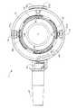
図1‐図5を参照すると、本発明に従って形成された取付け機構を具現した、移植用医療装置、より具体的には注入ポート2が示されている。この取付け機構は、注入ポート2で具現されて図面に例示されているが、取付け機構は、例示としてのみであり限定するものではないが、ペースメーカー、血管アクセスポート、注入ポート(胃バンドなどに使用)、および胃ペーシング装置を含め、使用に適した移植用医療装置に用いることができる。 Referring to FIGS. 1-5, an implantable medical device, more specifically an
注入ポート2は、隔壁リテーナ4、隔壁6、およびポート本体8を含む。一体形成された取付け機構を備えた注入ポート2は、1または複数のファスナー10、アクチュエータ12、および複数のリンク部材14を含む。 The
図4に示されているように、シリコーンなどの任意の好適な生体適合性材料から形成することができる隔壁6が、環状フラット18に近接して隔壁リテーナ4の内部キャビティ16内に部分的に配置されている。隔壁リテーナ4、ポート本体8、およびアクチュエータ12は、ポリエーテルエーテルケトン(PEEKとして知られている)などの十分な剛性および強度を有する任意の好適な生体適合性材料から形成することができる。ファスナー10およびリンク部材14は、ステンレス鋼などの任意の好適な生体適合性金属から形成することができる。 As shown in FIG. 4, a
ポート本体8は、環状部分の周りの隔壁6の上面に係合する環状リム20を含む。ポート本体8は、複数のピン22によって隔壁リテーナ4に保持されている。複数のピン22は、ポート本体8の凹部24aに形成された各孔24の中に配置され、隔壁リテーナ4の底部周辺の周りに形成された各凹部26の中に内側に延びている。ピン22は、ステンレス鋼などの任意の好適な生体適合性材料から形成することができる。 The
圧縮されていない状態での隔壁6の高さは、外径の周りで約5mmであり、圧縮されていない状態での直径は、約18mmである。レザバー20にアクセスできる露出された直径は約14mmである。環状リム20の底面と環状フラット18との間の距離は、隔壁6を約20%圧縮し、圧力下で十分に自己回復して流体密閉システムを維持して薄い厚みを可能とする約4mmである。 The height of the
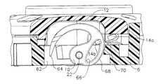
プレート28が、隔壁6および流体チャンバすなわちレザバー30の下側に延在する、隔壁リテーナ4の底部に形成された凹部16aに配置されている。図4に示されているように、プレート28は、側壁16bに接触していない。図示されている実施形態では、プレート28は、ステンレス鋼などの金属である。調節可能な胃バンドの大きさを調節するなどのために針を隔壁6に挿入して流体を流体チャンバ30に導入するかまたは流体チャンバ30から排出する際に、金属プレート28により、隔壁リテーナ4が穿刺から保護されると共に、針がレザバー30の底部に到達したことを示す触知の感覚を外科医が針から得ることができる。プレート28は、任意の好適な方法で隔壁リテーナ4に固定することができる。図示されている実施形態では、プレート28は、図4、図28、および図29に最もよく示されているようにプレート28の外周部の上に延在する保持リップ4aによって所定の位置に保持されている。初めは、保持リップ4aは環状リップとして上方に延びていて、隔壁リテーナ4の底部の凹部内にプレート28を挿入するための隙間を画定している。プレート28が凹部内に配置されたら、保持リップ4aを、曲げるまたは他の方法で変形させ、プレート28の外周部の少なくとも一部の上に延在させてプレート28を保持する。図示されている実施形態では、凹部16aの直径は、側壁16bの直径よりも小さく、環状リップを形成してその環状リップを保持リップ4aに変形するための余地が画定されている。プレート28は、インサート成型することができ、例示されているように成型された保持リップ4aを備えることができる。 A
隔壁リテーナ4は、流体チャンバ30に連通した、リテーナ4の底部に近接した外周部から延びた継手34によって画定された通路32を含む。図示されている実施形態では調節可能な胃バンド(不図示)につながったチューブ36が、コネクタ40によって、環状リブ38に対して圧迫された継手34に接続されている。コネクタ40は、詳細を後述するように、チューブ36の周りに配置され、ポート本体8に固定されている。スリーブ42が、環状リブ44によってコネクタ40に固定されたチューブ36の周りに配置されている。スリーブ42は、チューブ36に対する歪みを解放し、チューブ36が横方向に負荷がかかった時の捩れを防止している。 The
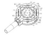
アクチュエータ12が、ポート本体8に固定されている。図示されている実施形態では、アクチュエータ12は、ポート本体8によって回転可能に支持された環状リングとして例示されているが、アクチュエータ12は、配置位置と非配置位置との間でファスナー10を移動させることができる任意の好適な構造とし、任意の好適な方法によって支持することができる。図5に示されているように、ポート本体8は、複数の外側下方に延びたタブ46を含む。図示されている実施形態では、4つのタブ46が等間隔で設けられている。アクチュエータ12は、タブ46に等しい数の対応する凹部48を含み、各凹部は弧状底部50を有する。アクチュエータ12をポート本体8に組み付ける際は、凹部48をタブ46に整合させ、アクチュエータ12を押し下げてタブ46を一時的に内側に撓ませ、タブ46が凹部48に達するとタブ46が外側に移動し、下縁46aが凹部48内に受容されてアクチュエータが保持される。タブ46の長さおよび凹部48の深さにより、詳細を後述するように、アクチュエータ12とポート本体8との間で軸端部の一定の遊びが可能となる。 An
アクチュエータ12は、ポート本体8の中心軸を中心に全体的に回転することができる。図示されている実施形態では、アクチュエータ12は、約40度回転することができるが、任意の好適な角度にすることができる。図示されている実施態様では、アクチュエータ12が配置方向に回転すると、ファスナー10が配置位置まで移動し、アクチュエータ12の完全な配置位置を越える回転は、端部48cのタブ46との接触によって制限されている。 The
戻り止めシステムが、各凹部48の側壁から内側に延びた一対の離間した突出戻り止めリブ48a、48bと、タブ46から外側に延びた対応する突出リブ46bによって形成されている。戻り止めシステムは、後述するように、アクチュエータ12が回転するのを防止するのに役立ち、ファスナー10が、振動または偶発的な負荷がかかった時に、完全に格納された状態または完全に延出して発射された状態から移動するのを防止するのに役立つ。 A detent system is formed by a pair of spaced projecting
アクチュエータ12は、任意の好適な器具に係合してアクチュエータ12に必要なトルクを伝達してファスナー10を作動した位置に延出させることができる複数の離間した開口またはスロット54を含む。スロット54は、図示された実施形態では矩形である市販の器具または後述する専用のアプライヤーに係合するように構成されている。ポート本体8は、後述する専用のアプライヤーと協働するように構成された、下側の外周部に配置された複数の凹部56を含む。 The
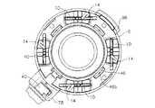
図6および図7も参照すると、隔壁リテーナ4は、その底部周辺の近傍から外側に延びた複数の位置合せタブ58を含む。位置合せタブ58aは、継手34と一体にできる。タブ58および58aはそれぞれ、ポート本体8の内面に形成された相補的な形状の凹部60内に配置され、隔壁リテーナ4がポート本体8に適切に整合する。 Referring also to FIGS. 6 and 7, the
図6は、格納位置のファスナー10を例示している。図から分かるように、ファスナー10は、ポート本体8に形成された各凹部またはスロット62内に配置されている。図7は、スロット62から延出した延出位置すなわち発射位置にあるファスナー10を例示している。アクチュエータ12の回転により、ファスナー10が格納位置から収納位置に移動する。 FIG. 6 illustrates the
図8‐図11は、アクチュエータ12および複数のファスナー10の1つの動作を例示する連続的な図面であって、1つのファスナー10に対する動作を、他の全てのファスナー10についても同じにし、一実施形態では、ファスナー10を配置位置から非配置位置に同時に移動させることができることを理解されたい。図8は、完全に格納された状態で、非配置位置にあり、尖った先端部64が露出しないようにスロット62内に完全に配置されているファスナー10を例示している。これにより、先端部64が外科医や他の物体を誤って突刺するのが防止される。アクチュエータ12は、凹部48とタブ46が許す範囲で反時計回りに回転している。この位置では、リブ46bは、図14に示されているようにリブ48bの時計周りの方向に位置している。リンク部材14の第1の端部14aが、ファスナー10の位置に相当する位置に離間して、アクチュエータ12によって回転可能に保持されている。第2の端部14bが、ファスナー10の開口66内に配置されている。 8-11 are sequential drawings illustrating the operation of one of the
取付け機構を作動させる際は、一体型アクチュエータ12を配置方向、一実施形態では時計回りの方向(取付け機構を作動させるように構成された任意の好適な方向を用いることができる)に回転させ、リブ46bがリブ48bを通過するようにする。この通過により、外科医に対して、触知の感覚の信号に加えて可聴の音の信号が生成される。リンク部材14の第2の端部14bは、ファスナー10のカム面68とアクチュエータ12の作動カム面70との間の相互作用によって、ファスナー10を延出位置に回転させる力がファスナー10に伝達されるため、作動中にスロット66内を自由に移動する。アクチュエータ12が時計回りに回転すると、作動カム面70がカム面68に係合してこのカム面68を押し、これによりファスナー10がピボットピン22を中心に回転する。作動カム面70からの力の大部分が、ピボットピン22に対して中心がずれてカム面68に対して接線方向に作用するため、ファスナー10が回転する。作動の際、リンク部材14の端部14bがスロット66内を自由に回転することができるため、ファスナー10を回転させる力が加えられない。 When actuating the attachment mechanism, the
図9において、ファスナー10は、アクチュエータ12の時計回りの回転の結果として約90度、回転範囲の途中まで回転している。アクチュエータ12が時計回りに回転すると、作動カム面70とカム面68との間の力により、構成要素の公差によってアクチュエータ12が僅かに上方に移動する。アクチュエータ12が、図9に示されている位置からさらに時計回りに回転すると、作動カム面70が、引き続きカム面68に係合してこのカム面68を押し、これによりファスナー10がさらに反時計回りに回転する。 In FIG. 9, the
図10において、アクチュエータ12は、完全に延出した位置まで時計回りに回転して、リブ46bが戻り止めリブ48aを越えている(図15を参照)。この位置では、ファスナー10は、完全に延出した位置、例示されている実施形態ではほぼ180度回転し、先端部64が凹部62内に配置されている。この位置では、作動カム面70が中心を越えていて、アクチュエータ12は、カム面68がアクチュエータ12を回転させるのではなく押し上げる方向に作動カム面70を押すため、ファスナー10にかかる非配置の力によって戻されない。ファスナー10の先端部分は、ビームとして実質的に構成され、図示されているように、断面がその長さに沿って概ね矩形であり、尖った先端部64に向かってテーパ状になっている。ファスナー10が約180度延出した完全に延出した状態の配置位置では、ファスナー10に対して作用しうる力が、ファスナー10を回転させるのではなく、ピボットピン22によって画定されたピボット軸を介して作用する傾向にある。ピン22は、ファスナー10と別個の部品として例示されているが、これらを一体にする、または単一構造にすることもできることを理解されたい。 In FIG. 10, the
移植装置を除去または再配置するなどのためにファスナー10を格納するのが望ましい場合は、アクチュエータ12を、非配置方向、図示されている一実施形態では半時計周りに回転させることができる。図10に示されているアクチュエータ12の位置から、アクチュエータ12を反時計回りの方向に回転させ、ファスナー10が回転することなく作動カム面70をカム面68に対してスライドさせる。図示されている実施形態では、アクチュエータ12のさらなる反時計回りの回転により、作動カム面70がカム面68から離れる。この時、リンク部材の第2の端部14bが、リンク部材14がスロット66を引っ張り始めてファスナー10を回転させて格納し始めるスロット66の一端などのスロット66の所定の位置に達するまで、ファスナー10に対して実質的に回転の力がかからない。 If it is desired to retract the
図11に示されているように、アクチュエータ12は、図10に示されている位置に比べて反時計回りの方向に進んでおり、ファスナー10は、その回転範囲のほぼ中間まで回転している。図9と図11との比較から分かるように、アクチュエータ12は、取付け機構が作動または非作動(格納)であるかによって、ファスナー10が同じ位置でも異なる位置になる。これは、作動カム面70がカム68を直接押しているのに対して、リンク部材14がスロット66を引っ張るときに起こる空転によるものである。ファスナー10を完全に格納する際は、アクチュエータ12を、戻り止めリブ46bが戻り止めリブ48bをスナップ式に越えるまで回転させる。 As shown in FIG. 11, the
図8を参照すると、ファスナー10が完全に非配置位置に達すると、先端部64をスロットすなわち凹部62内に完全に格納することができる。ファスナー10によってさらなる移動が防止されているリンク部材14によって、アクチュエータ12のさらなる非配置方向への回転が防止されている。 Referring to FIG. 8, once the
図2および図3を参照すると、アクチュエータ12は、アクチュエータが非配置位置にある時にポート本体8に形成された対応する開口52bに整合する開口52aを備えている。一体型取付け機構が用いられない場合は、外科医が開口52aと52bを用いて注入ポート2を接合する。 2 and 3, the
図12および図13を参照すると、アクチュエータ12のない取付け機構が示されている。リンク部材14は、第1の端部14aがアクチュエータ12によって支持されている時の配置状態および非配置状態にある実際の位置で示されている。 Referring to FIGS. 12 and 13, an attachment mechanism without the
図14および図15を参照すると、注入ポート2で具現されている取付け機構のアクチュエータリング戻り止めシステムの一部および視覚位置表示の平面図が例示されている。図14において、取付け機構は、格納された非配置状態すなわち非配置位置にある。この位置では、戻り止めリブ46bは、戻り止めリブ48bの時計回りの方向に位置し、非配置戻り止め位置にある。図15において、取付け機構は、作動位置すなわち配置位置にある。この位置では、戻り止めリブ46bは、戻り止めリブ48bの反時計回りの方向に位置し、配置戻り止め位置にある。 Referring to FIGS. 14 and 15, there is illustrated a plan view of a portion of the actuator ring detent system of the mounting mechanism embodied in the
図14および図15は、取付け機構の状態を示す視覚表示を例示している。図14に示されているように、アクチュエータリング12と一体成型されたロック解除アイコン72およびロックアイコン74などの印を用いることができる。任意の好適なグラフィック表示を用いることができ、印刷または他の好適な方法で設けることができる。ポート本体6は、可動表示の基準点となる指示器76を含むことができる。アクチュエータ12の両方向の運動を示すために矢印を設けることができる。 14 and 15 illustrate a visual display showing the state of the attachment mechanism. As shown in FIG. 14, marks such as an
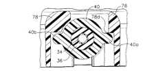
図16‐図18は、コネクタ40とポート本体6との間のロック接続を例示している。図16は、延長部78によって部分的に取り囲まれた継手34を示す組立分解斜視図である。図17は、コネクタ40が概ね継手34の周りに配置され、チューブ36が延長部78の外周スロット78cに整合している延長部78の断面図である。コネクタ40は、そのコネクタから外側に延出した一対のタブ40aおよび40bを含む。組み立てる際は、タブ40aおよび40bを延長部78の開口78aおよび78bに整合させて、コネクタ40を、チューブ36および継手34に沿って案内する。タブ40aおよび40bを外周スロット78cに整合させて、コネクタ40を回転させて所定の位置に固定する。回転の際、戻り止めエッジ78dが、タブ40aの回転の抵抗となるが、戻り止めエッジ78dは、タブ40aがこれを越えて図18に示されている固定位置まで回転できる寸法に形成されている。 FIGS. 16-18 illustrate the locking connection between the
図19は、注入ポート2を取り扱う際に尖った先端部64の偶発的な露出から使用者を保護するべくファスナー10を覆う、注入ポート2の底部に取外し可能に固定できる安全キャップ80を例示している。安全キャップ80は、環状凹部88を画定する隆起中央部86および環状リム84を備えた本体82を含む。安全キャップ80は、任意の好適な構造によって注入ポートに配置して取り付けることができる。図示されているように、本体82は、隆起中央部86から上方に延出した複数の弧状保持タブ90を含む。弧状保持タブ90は、図3、図6、および図7に最もよく示されている対応する弧状スロット92に相補的な形状であって、図示されているようにリブを有することができる。安全キャップ80は、弧状保持タブ90を、このタブ90を保持する大きさである弧状スロット92内に挿入して注入ポート2に固定する。したがって、ファスナー10は、このファスナー10が安全キャップ80に接触することなく延出できる大きさの環状凹部88に整合する。図示されているように、弧状保持タブ90と弧状スロット92が、同じ大きさであって等しく離間しているため、安全キャップ80を特定の位置に合わせなくても、4つの異なった位置で注入ポート2に固定することができる。安全キャップ80は、グリップしやすい隆起した複数のリブ96を備えたプルタブ94を含む。プルタブ94は、任意の好適な向きに配置することができるが、この実施形態では、プルタブ94と弧状保持タブ90との間の相対位置により、プルタブがコネクタ40の方向に対して45度の角度をなしている。タブ90およびスロット92は、任意の好適な形状にすることができる。 FIG. 19 illustrates a
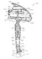
前述したように、取付け機構は、市販の器具にスロット54を係合させて、または専用のアプライヤーによって作動させることができる。図20は、注入ポート2を配置、作動、作動解除、除去、または再配置するように構成された、参照番号100で示されているアプライヤーを例示している。アプライヤーに適用する本発明の態様の実施がここに開示する特定のアプライヤーの実施形態に限定されるものではないことを理解されたい。 As previously described, the attachment mechanism can be actuated by engaging the
図20に示されているように、アプライヤー100は、本体102、ロケータ104、アクチュエータ106、および安全スイッチ108を含む。後述するように、注入ポート2は、延長部78およびタブ96を整合スロット110および112内に配置してロケータ104に取り付けることができる。ロケータ104は、移植の際に注入ポート2を容易かつ良好に視認できるように本体102に対して所定の角度をなしている。図示されている実施形態では、この角度は20度であり、本体102のシャフト部分の長さは10cmである。 As shown in FIG. 20, the
図21を参照すると、本体102は、互いに組み付けられて内部構成要素を受容する第1の半体102aおよび第2の半体102bを含む。位置決めピン202、ピボットピン114、および相互はぎを除き、本体の半体102aおよび102bは、互いに実質的に同様である。本体の半体102aから延出しているように例示されている位置決めピン202はそれぞれ、本体の半体102bに形成された相補的な形状の開口(不図示)内に嵌合する。複数の位置決めピン202が開口に係合することにより、本体の半体102aと102bが互いに十分に保持される。別法では、ピン202が本体の半体102bから延出し、本体の半体102aが開口を備えることができる。任意の好適な構造を用いて、本体の半体102aと102bを互いに取り付けて固定することができる。 Referring to FIG. 21, the
アクチュエータ106は、第1の半体106aおよび第2の半体106bを含む。アクチュエータの半体106aから延出しているように例示されている位置決めピン204がそれぞれ、アクチュエータの半体106bに形成された相補的な形状の開口(不図示)内に嵌合する。別法では、ピン204がアクチュエータ半体106bから延出し、アクチュエータ半体106aが開口を備えることができる。任意の好適な構造を用いて、アクチュエータ半体106aと106bを互いに取り付けて固定することができる。本体の半体102bは、ピボット孔116aおよび116bを貫通して開口114aに至る、一端でアクチュエータ106を回転可能に支持するピボットピン114bを含む。本体の半体102aは、安全スイッチ108を回転可能に支持するピボットピン118b(図22を参照)を含む。本体の半体102aおよび102b、ロケータ104、アクチュエータ半体106aおよび106b、および安全スイッチ108は、ポリカーボネートなどの任意の生体適合性材料から形成することができる。 The
図21‐図24を参照すると、アプライヤー100は、カム120、可撓性の軸124を備えた駆動軸122、駆動軸ピン126、カム戻しバネ128、安全付勢バネ130、およびアクチュエータ132を含む。アクチュエータ132は、医療インプラントの取付け機構の配置または非配置を行うように構成されている。カム120は、軸134およびカムカラー136を含む。軸134の上端部は、T型構造の交差部材138を備えている。カムカラー136は、中空の内部、およびカムカラー136の両側に形成された一対の離間した相補的な形状のカムトラック140aおよび140bを画定している。駆動軸122の上端部122aは、カムカラー136によって画定された中空内部内に部分的に配置され、駆動軸ピン126によって中空内部内に保持されている。駆動軸ピン126は、各端部が各カムトラック140aおよび140b内に配置される大きさを有する。中空内部の長さは、上端部122aがその中空内部内で往復運動すると、カムトラック140aおよび140bにより、駆動軸ピン126を介して駆動軸122が回転できる長さである。カム120、駆動軸122、およびアクチュエータ132は、十分な剛性および強度を有する任意の好適な材料から形成することができる。図示されている実施形態では、カム120およびアクチュエータ132は、Vectra(商標)LCPなどの液晶ポリマーから形成され、駆動軸122は、Noryl(商標)などのPPE+PSから形成されている。駆動軸ピン126およびカム戻しバネ128は、ステンレス鋼などの任意の好適な材料から形成することができる。 21-24, the
カム120は、図示されているような一実施形態では、往復運動できるように本体部分102aと102bとの間に保持されている。カムカラー136は、トラック140aおよび140bが形成されている概ね平坦な離間した外面142aおよび142bを有する。これらの外面142aおよび142bは、本体部分102aおよび102bに形成されたガイド壁144aと144bとの間に配置されている。カムカラー136は、本体部分102aおよび102bのそれぞれに形成されたガイド148aおよび148b(不図示)によって軸方向の往復運動が案内される対向した溝146aおよび146b(図23を参照)も含む。軸134の上端部および交差部材138は、アクチュエータ半体106aと106bとの間に挟まれて配置されている。各アクチュエータ半体106aおよび106bは、その内面から延びた一対の離間した壁部150aおよび150bによって画定されたカムトラック150を含む。カムトラック150は、アクチュエータ106がピン114を中心に回転する時に交差部材138を受容して案内し、カム120を本体102内において下方に線形に前進させるように構成されている。 In one embodiment as shown, the
駆動軸122は、本体の半体102aおよび102bのそれぞれに形成されたスロット154aおよび154b(不図示)内に受容される環状カラー152を含む。スロット154aおよび154bは、駆動軸122を回転可能に支持する。駆動軸122およびカム120は、互いに概ね整合して同一線上にあり、本体102の軸部分の軸線を画定している。カム120が下方に進むと、駆動軸ピン126がカムトラック140aおよび140bに沿って移動し、これにより駆動軸122が回転して直線運動が回転運動に変換される。カム戻しバネ128は、カムカラー136に対して公称戻し力(nominal return force)を付与している。 The
可撓性の軸124は、本体の各半体102aおよび102bに形成された複数のリブ156によって支持されている。これらのリブ156は、湾曲した可撓性軸124を支持し、本体102の軸に対して所定の角度をなして配置されているアクチュエータ132へ回転運動を伝達することができる。可撓性軸124は、ステンレス鋼などの任意の好適な生体適合性材料から形成することができる。図示されている実施形態では、可撓性軸124は、ワイヤが巻かれた複数の層を有する中心コアを備えたより構造(stranded construction)を有する。可撓性軸124の端部124aおよび124bはそれぞれ、端部の回転の遊びを十分に制限して回転運動のロスを防止または最小限にする任意の好適な要領で、端部122bおよびアクチュエータ132に取り付けることができる。図示されている実施形態では、端部124aは、端部122b内にオーバーモールドされ、端部124bは、アクチュエータ132内にプレス嵌めされている。別法では、端部124aを端部122b内にプレス嵌めし、端部124bをアクチュエータ132内にオーバーモールドする、両方ともプレス嵌めする、または両方ともオーバーモールドすることができる(取付けできるように、これに対応してロケータ104の構造を変更する)。 The
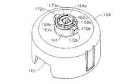
図25‐図29を参照すると、アクチュエータ132は、ディスク状部材158およびそのディスク状部材から上方に延出した軸160を含む。軸160の上端部は、外側に延びた一対のタブ162aおよび162bを含む。ロケータ104は、内部に孔166を画定しているハブ164を含む。孔166は、軸160を受容して回転可能に維持する形状であり、外側に延びた2つ弧状凹部168aおよび168bを含む。これらの弧状凹部168aおよび168bは、ハブ164を孔166内に挿入できるように、タブ162aおよび162bの組立の隙間を提供するように構成されている。軸160およびハブ164の長さは、ハブ164に対してアクチュエータ132を軸方向に保持しながらアクチュエータ132の回転が可能となるように、タブ162aおよび162bをハブ164の上面164aに配置できる長さである。ストッパー170aおよび170bが上面164aから上方に延出しており、アクチュエータ132の回転を制限している。孔166は、ロケータ104の中心軸を画定しており、この軸を中心にアクチュエータ132が回転する。ロケータ104の中心軸は、前述したように、本体102の軸部分の軸に対して所定の角度をなしている。 Referring to FIGS. 25-29, the
ハブ164は、ポートアクチュエータ132を本体102に維持して回転を防止する、相反して延出した一対のタブ172aおよび172bを含む。本体の半体102aおよび102bはそれぞれ、タブ172aおよび172bに相補的な形状の凹部174a(図21を参照)および174b(不図示)を含む。
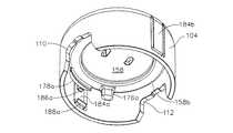
図26および図示27を参照すると、アクチュエータ132のディスク状部材158は、ロケータ104内に配置されている。アクチュエータ132は、ディスク状部材158の周辺部158aの近傍から延出した一対の離間したポスト176aおよび176bを含む。ポスト176aおよび176bは、開口54と相補的な形状である。図示されている実施形態では、ポスト176aおよび176bの先端部は、開口54内に入りやすいようにテーパ状である。任意の好適な構造を用いて、アクチュエータ12を作動させることができる、アクチュエータ132とアクチュエータ12との解除可能な結合を行うことができる。 Referring to FIGS. 26 and 27, the disk-
ディスク状部材158はまた、このディスク状部材158の外周部158aから外側上方に延びた一対の離間したカム178aおよび178bを含む。図27は、ディスク状部材158の底面近傍で切り取られたカム178aの断面を例示している。カム178aおよび178bは、外周部158aから表面182aおよび182bまで延出したランプ180aおよび180bをそれぞれ含む。各表面182aおよび182bは、図示されている実施形態に示されているように、概ね一定の半径を有する弧状である。 The disk-shaped
図示されている実施形態では、ロケータ104は、一対の離間したカンチレバーアーム184aおよび184bを含み、これらのカンチレバーアーム184aおよび184bはそれぞれ、リブ186aおよび186bを有する。見やすくするために、図27は、カム178aと同じ高さでリブ186aを切り取ったアーム184aの断面を例示している。アーム184aおよび184bはそれぞれ、先端部に、内側に延出したフランジ188aおよび188bを備えている。フランジ188aおよび188bは、注入ポート2がロケータ104に保持された時にレッジ56aに係合するように構成された、ポート本体6の凹部56に相補的な形状を有する。 In the illustrated embodiment,
図示されている実施形態では、非作動状態では、ポスト176aおよび176bはそれぞれ、アーム184aおよび184bに概ね整合しているが、ポスト176aおよび176bは、図示されている実施形態では開口54であるアクチュエータ12の作動機構の位置に一致する任意の位置にすることができる。アクチュエータ106が押圧されると、アクチュエータ132が回転し(図示されている実施形態では、下から見て半時計周りの方向)、カム178aおよび178bが前進して、ランプ180aおよび180bがそれぞれ、リブ186aおよび186bに接触してアーム184aおよび184bが外側に撓む。表面182aおよび182bが、リブ186aおよび186bに係合すると、アーム184aおよび184bが十分な距離撓んで、フランジ188aおよび188bが凹部56から出てレッジ56aに接触しない位置までフランジ188aおよび188bが移動し、これにより注入ポート2がロケータ104から解放される。 In the illustrated embodiment, in an inoperative state,
図28は、延長ハウジング78およびタブ96がそれぞれスロット110および112内に配置され(図20を参照、図28には不図示)、ロケータ104内に配置され保持された注入ポート2を例示している。図示されているように、ポスト176aおよび176bは、アクチュエータ12の開口54内に延在し、フランジ188aおよび188bが、レッジ56aに近接した凹部56内に延在している。注入ポート2をロケータ104内に挿入する際に、安全キャップ80を注入ポート2に接続してファスナー10を覆う(図28には不図示)。 FIG. 28 illustrates the
図20および図22も参照されたい。注入ポート2をロケータ104内に挿入する際、アクチュエータ132が非配置位置にくるように、アクチュエータ106を非配置位置にする。アクチュエータ12を非配置位置にし、延長ハウジング78およびタブ96がそれぞれスロット110および112内に配置されるようにロケータ104内に挿入する。 See also FIGS. 20 and 22. When the
アクチュエータ106は、図20に例示されているように、アクチュエータ106が完全に非配置状態にあることを示すロック解除アイコン190、およびアクチュエータ106が配置状態にあることを示すロックアイコン192などの視覚表示を含む。このような視覚表示は、アクチュエータ106と一体に成型する、接着フィルムなどとして貼り付ける、またはアクチュエータ106に直接印刷するなどの任意の好適な方法で設けることができる。例示されている表示では、ロック解除アイコン190は、本体102の上縁の近傍で視認できるが、表示を明示するために本体102に設けられた窓開きなどの他の表示構造も用いることができる。
使用する際、外科医が、ロケータ104および本体102の一部(必要に応じて)を切開部から挿入し、医療インプラント(図示されている実施形態では注入ポート2)を取り付ける体組織近傍の所望の位置に配置する。ロケータ104と本体102との間の角度により、外科医が移植部位を直接視認することができる。注入ポート2を所定の位置に配置したら、1または複数のファスナー10を、非配置位置から環状経路に沿って配置位置に移動させて組織に係合させる。ファスナー10により、注入ポート2を体組織に固定することができる。この場合の保持力は、縫合糸を用いて固定した場合と同等またはそれ以上である。安全スイッチ108を、ピボットピン118を中心に回転させて、ロックアウトタブ194を下側開口196から引き抜き、アクチュエータ106がピボットピン114を中心に回転できるようにする。この動作により、カムトラック150が交差部材138を下方に移動させ、これによりカムカラー136が駆動軸122を回転させ、これによりアクチュエータ132がロケータ104に対して回転する。 In use, the surgeon inserts the
アクチュエータ132の回転により、アクチュエータ12が回転して作動する。延長部78およびタブ96とスロット110および112のそれぞれの係合により、ポート本体8の回転が防止され、アクチュエータ12とポート本体8との相対運動が可能となる。 Due to the rotation of the
アクチュエータ106が配置位置に達すると、ロックアウトタブ194が上部開口198内に押され、アクチュエータ106が配置位置に保持される。図示されている実施形態では、ロックアウトタブ194が上部開口198内にスナップ嵌めされた時に音を発するよう、バネ130が、ロックアウトタブ194を十分に付勢して、アクチュエータ106、従ってアクチュエータ12、およびファスナー10が完全に配置されたことを知らせる可聴の音の信号を生成する。図29に例示されているように、アクチュエータ106が配置位置にあると、アクチュエータ12が回転してファスナー10が腹直筋鞘などの体組織を刺入した配置位置にある。カム178aおよび178bが、表面182aおよび182bがリブ186aおよび186bに近接した位置まで回転し、アーム184aおよび184bが外側に撓み、フランジ188aおよび188bが凹部56から出てレッジ56aとの係合が解除される。注入ポート2が体組織に固定され、ロケータ104から解放されたら、外科医が、ロケータ104を取り出して注入ポート2を留置することができる。取付け機構の状態の視覚表示がインプラントに設けられている場合は、外科医が、取付け機構が完全に配置されたか否かを確認することができる。 When the
注入ポート2で具現されている取付け機構は、医療インプラントである注入ポート2を移動させて再配置したり、患者から除去したりできるように可逆式に構成されている。再配置または除去する際は、アクチュエータ106が配置位置で、ロケータ104を注入ポート2の上に配置し、ポスト176aおよび176bが凹部54に係合するように延長部78およびタブ96をスロット110および112に位置合わせする。外科医がアクチュエータ106の延長部200を引き上げながら、安全スイッチ108を回転させてロックアウトタブ194を上部開口198から引き抜く。カム戻しバネ128がカムカラー136を上方に付勢するが、延長部200を用いて戻す力をさらに加えることができる。交差部材138がカムトラック150によって引き上げられると、アクチュエータ132がアクチュエータ12を回転させ、ファスナー10が同時に配置位置から非配置位置に移動すると共に、カム178aおよび178bがリブ186aおよび186bから係合解除され、これによりフランジ188aおよび188bが凹部56およびレッジ56aに係合して、注入ポート2がロケータ104内に保持される。アクチュエータ106が非配置位置に移動すると、ロックアウトタブ194が下部開口196内にスナップ嵌めされ、アクチュエータ106が完全に非配置位置にあることを示す可聴の音の信号が生成され、注入ポート2が体組織から係合解除され、再配置または除去することができる。 The attachment mechanism embodied in the
要約すると、本発明の概念を用いることにより得られる多数の利点を説明した。本発明の1または複数の実施形態の上記説明は、例示および記載目的である。開示した正確な形態に本発明を限定または制限するものではない。上記説明から変更形態または改良形態が可能である。本発明の原理およびその実際の適用例を例示して、当業者が本発明を様々な実施形態に利用でき、かつ特定の用途に適した様々な変更形態に想到するように、1または複数の実施形態を選択して記載した。本発明の範囲は、添付の特許請求の範囲によって規定されるものである。 In summary, a number of advantages have been described that can be obtained by using the concepts of the present invention. The above description of one or more embodiments of the invention is for purposes of illustration and description. It is not intended to be limiting or to limit the invention to the precise form disclosed. Modifications or improvements are possible from the above description. Illustrating the principles of the invention and its practical applications, one or more of those skilled in the art will be able to utilize the invention in various embodiments and contemplate various modifications suitable for a particular application. An embodiment was selected and described. The scope of the present invention is defined by the appended claims.
〔実施の態様〕
(1)ハウジングを含む外科的に移植可能な注入ポートにおいて、
前記ハウジングが、当該ハウジングから基端側に延びたレザバーを画定する側壁を有する底部を含み、前記底部が、金属部材を含み、前記金属部材が、前記側壁の末端部の近傍の領域で前記側壁に接触していない、
注入ポート。
(2)実施態様(1)に記載の注入ポートにおいて、
前記金属部材が、その少なくとも一部の上に延在する保持リップによって所定の位置に保持されている、注入ポート。
(3)実施態様(2)に記載の注入ポートにおいて、
前記ハウジングが、前記底部に近接した凹部を画定しており、前記凹部が周辺部を備え、前記保持リップが、前記周辺部の少なくとも一部に近接した部分から上方に延出し、前記金属部材の少なくとも一部の上に延在するように変形されている、注入ポート。
(4)実施態様(2)に記載の注入ポートにおいて、
前記保持リップが環状である、注入ポート。
(5)実施態様(4)に記載の注入ポートにおいて、
前記保持リップが、前記凹部の周りで連続している、注入ポート。Embodiment
(1) in a surgically implantable injection port including a housing;
The housing includes a bottom having a sidewall defining a reservoir extending proximally from the housing, the bottom includes a metal member, and the metal member is in the region near the distal end of the sidewall. Not touching the
Injection port.
(2) In the injection port according to the embodiment (1),
An injection port, wherein the metal member is held in place by a retaining lip extending over at least a portion thereof.
(3) In the injection port according to the embodiment (2),
The housing defines a recess close to the bottom, the recess includes a peripheral portion, and the holding lip extends upward from a portion close to at least a portion of the peripheral portion; An injection port that is deformed to extend over at least a portion.
(4) In the injection port according to the embodiment (2),
An injection port, wherein the retaining lip is annular.
(5) In the injection port according to embodiment (4),
An injection port, wherein the retaining lip is continuous around the recess.
(6)外科的に移植可能な注入ポートにおいて、
(a)レザバーを画定するハウジングと、
(b)流体密閉膜によって画定された上部を含む前記レザバーと、
(c)前記膜に近接して配置された環状リングであって、前記膜に対して圧縮力を加え、前記圧縮力が、針によって複数回刺入された後も前記膜の流体の密閉を維持する、前記環状リングと、
を含む、注入ポート。
(7)実施態様(6)に記載の注入ポートにおいて、
前記膜がシリコーンである、注入ポート。
(8)実施態様(6)に記載の注入ポートにおいて、
前記環状リングが、前記膜の環状部分をほぼ20%圧縮する、注入ポート。
(9)実施態様(8)に記載の注入ポートにおいて、
前記膜が、外径と厚みを有し、前記厚みに対する前記外径の比率がほぼ3.6である、注入ポート。(6) In a surgically implantable injection port,
(A) a housing defining a reservoir;
(B) the reservoir including an upper portion defined by a fluid tight membrane;
(C) An annular ring disposed in proximity to the membrane that applies a compressive force to the membrane and seals the fluid in the membrane after the compressive force has been inserted multiple times by a needle. Maintaining the annular ring;
Including injection port.
(7) In the injection port according to embodiment (6),
An injection port, wherein the membrane is silicone.
(8) In the injection port according to embodiment (6),
An injection port, wherein the annular ring compresses the annular portion of the membrane by approximately 20%.
(9) In the injection port according to embodiment (8),
An injection port, wherein the membrane has an outer diameter and a thickness, and the ratio of the outer diameter to the thickness is approximately 3.6.
Claims (6)
Translated fromJapanese前記ハウジングが、当該ハウジングから基端側に延びたレザバーを画定する側壁を有する底部を含み、前記底部が、金属部材を含み、前記金属部材が、前記側壁の末端部の近傍の領域で前記側壁に接触していない、
注入ポート。In a surgically implantable injection port including a housing,
The housing includes a bottom having a sidewall defining a reservoir extending proximally from the housing, the bottom includes a metal member, and the metal member is in the region near the distal end of the sidewall. Not touching the
Injection port.
前記金属部材が、その少なくとも一部の上に延在する保持リップによって所定の位置に保持されている、注入ポート。The injection port according to claim 1.
An injection port, wherein the metal member is held in place by a retaining lip extending over at least a portion thereof.
前記ハウジングが、前記底部に近接した凹部を画定しており、前記凹部が周辺部を備え、前記保持リップが、前記周辺部の少なくとも一部に近接した部分から上方に延出し、前記金属部材の少なくとも一部の上に延在するように変形されている、注入ポート。Infusion port according to claim 2,
The housing defines a recess close to the bottom, the recess includes a peripheral portion, and the holding lip extends upward from a portion close to at least a portion of the peripheral portion; An injection port that is deformed to extend over at least a portion.
前記保持リップが環状である、注入ポート。Infusion port according to claim 2,
An injection port, wherein the retaining lip is annular.
前記保持リップが、前記凹部の周りで連続している、注入ポート。The injection port according to claim 4,
An injection port, wherein the retaining lip is continuous around the recess.
(a)レザバーを画定するハウジングと、
(b)流体密閉膜によって画定された上部を含む前記レザバーと、
(c)前記膜に近接して配置された環状リングであって、前記膜に対して圧縮力を加え、前記圧縮力が、針によって複数回刺入された後も前記膜の流体の密閉を維持する、前記環状リングと、
を含む、注入ポート。In a surgically implantable injection port,
(A) a housing defining a reservoir;
(B) the reservoir including an upper portion defined by a fluid tight membrane;
(C) An annular ring disposed in proximity to the membrane that applies a compressive force to the membrane and seals the fluid in the membrane after the compressive force has been inserted multiple times by a needle. Maintaining the annular ring;
Including injection port.
Applications Claiming Priority (2)
| Application Number | Priority Date | Filing Date | Title |
|---|---|---|---|
| US11/166,611 | 2005-06-24 | ||
| US11/166,611US7651483B2 (en) | 2005-06-24 | 2005-06-24 | Injection port |
Publications (2)
| Publication Number | Publication Date |
|---|---|
| JP2007000643Atrue JP2007000643A (en) | 2007-01-11 |
| JP5063941B2 JP5063941B2 (en) | 2012-10-31 |
Family
ID=37056740
Family Applications (1)
| Application Number | Title | Priority Date | Filing Date |
|---|---|---|---|
| JP2006174190AExpired - Fee RelatedJP5063941B2 (en) | 2005-06-24 | 2006-06-23 | Injection port |
Country Status (15)
| Country | Link |
|---|---|
| US (1) | US7651483B2 (en) |
| EP (1) | EP1736196B2 (en) |
| JP (1) | JP5063941B2 (en) |
| KR (1) | KR20060135552A (en) |
| CN (1) | CN1891163B (en) |
| AT (1) | ATE403466T1 (en) |
| AU (1) | AU2006202358B2 (en) |
| BR (1) | BRPI0602352B8 (en) |
| CA (1) | CA2550714C (en) |
| DE (1) | DE602006002068D1 (en) |
| ES (1) | ES2310894T5 (en) |
| IL (1) | IL176172A0 (en) |
| PL (1) | PL1736196T5 (en) |
| RU (1) | RU2434650C2 (en) |
| SG (1) | SG128626A1 (en) |
Cited By (5)
| Publication number | Priority date | Publication date | Assignee | Title |
|---|---|---|---|---|
| EP2422838A1 (en) | 2010-08-26 | 2012-02-29 | Tyco Healthcare Group LP | Implantable central venous port |
| EP2441490A1 (en) | 2010-09-29 | 2012-04-18 | Tyco Healthcare Group LP | Subcutaneous implantable port and method for producing the same |
| JP2012076250A (en)* | 2010-09-30 | 2012-04-19 | Nihon Covidien Kk | Molding mold for constitutional part of subcutaneous implantable port, subcutaneous implantable port, and method of manufacture thereof |
| US10926396B2 (en) | 2018-06-19 | 2021-02-23 | Leatherman Tool Group, Inc. | Tool having one or more rotatable tool members |
| US11292105B2 (en) | 2016-06-01 | 2022-04-05 | Leatherman Tool Group, Inc. | Multipurpose tool having accessible tool members |
Families Citing this family (163)
| Publication number | Priority date | Publication date | Assignee | Title |
|---|---|---|---|---|
| DK1553878T3 (en)* | 2002-08-28 | 2010-05-31 | Allergan Inc | Fatigue resistant gastric banding device |
| US7901419B2 (en)* | 2002-09-04 | 2011-03-08 | Allergan, Inc. | Telemetrically controlled band for regulating functioning of a body organ or duct, and methods of making, implantation and use |
| US7862546B2 (en)* | 2003-06-16 | 2011-01-04 | Ethicon Endo-Surgery, Inc. | Subcutaneous self attaching injection port with integral moveable retention members |
| US8715243B2 (en)* | 2003-06-16 | 2014-05-06 | Ethicon Endo-Surgery, Inc. | Injection port applier with downward force actuation |
| US7850660B2 (en)* | 2003-12-19 | 2010-12-14 | Ethicon Endo-Surgery, Inc. | Implantable medical device with simultaneous attachment mechanism and method |
| US8162897B2 (en)* | 2003-12-19 | 2012-04-24 | Ethicon Endo-Surgery, Inc. | Audible and tactile feedback |
| US20050228415A1 (en)* | 2004-03-23 | 2005-10-13 | Michael Gertner | Methods and devices for percutaneous, non-laparoscopic treatment of obesity |
| US7255675B2 (en)* | 2004-03-23 | 2007-08-14 | Michael Gertner | Devices and methods to treat a patient |
| US20060195139A1 (en)* | 2004-03-23 | 2006-08-31 | Michael Gertner | Extragastric devices and methods for gastroplasty |
| WO2006049725A2 (en)* | 2004-03-23 | 2006-05-11 | Minimus Surgical Systems | Surgical systems and devices to enhance gastric restriction therapies |
| US7946976B2 (en)* | 2004-03-23 | 2011-05-24 | Michael Gertner | Methods and devices for the surgical creation of satiety and biofeedback pathways |
| US7955357B2 (en) | 2004-07-02 | 2011-06-07 | Ellipse Technologies, Inc. | Expandable rod system to treat scoliosis and method of using the same |
| US7775966B2 (en) | 2005-02-24 | 2010-08-17 | Ethicon Endo-Surgery, Inc. | Non-invasive pressure measurement in a fluid adjustable restrictive device |
| US8016744B2 (en) | 2005-02-24 | 2011-09-13 | Ethicon Endo-Surgery, Inc. | External pressure-based gastric band adjustment system and method |
| US8066629B2 (en) | 2005-02-24 | 2011-11-29 | Ethicon Endo-Surgery, Inc. | Apparatus for adjustment and sensing of gastric band pressure |
| US7699770B2 (en) | 2005-02-24 | 2010-04-20 | Ethicon Endo-Surgery, Inc. | Device for non-invasive measurement of fluid pressure in an adjustable restriction device |
| US7927270B2 (en) | 2005-02-24 | 2011-04-19 | Ethicon Endo-Surgery, Inc. | External mechanical pressure sensor for gastric band pressure measurements |
| US7775215B2 (en) | 2005-02-24 | 2010-08-17 | Ethicon Endo-Surgery, Inc. | System and method for determining implanted device positioning and obtaining pressure data |
| US7658196B2 (en) | 2005-02-24 | 2010-02-09 | Ethicon Endo-Surgery, Inc. | System and method for determining implanted device orientation |
| US8870742B2 (en) | 2006-04-06 | 2014-10-28 | Ethicon Endo-Surgery, Inc. | GUI for an implantable restriction device and a data logger |
| US8152710B2 (en) | 2006-04-06 | 2012-04-10 | Ethicon Endo-Surgery, Inc. | Physiological parameter analysis for an implantable restriction device and a data logger |
| US20070270770A1 (en)* | 2006-05-18 | 2007-11-22 | Medical Components, Inc. | Venous access port assembly and method of making same |
| US7862502B2 (en) | 2006-10-20 | 2011-01-04 | Ellipse Technologies, Inc. | Method and apparatus for adjusting a gastrointestinal restriction device |
| US8246533B2 (en) | 2006-10-20 | 2012-08-21 | Ellipse Technologies, Inc. | Implant system with resonant-driven actuator |
| US7655004B2 (en)* | 2007-02-15 | 2010-02-02 | Ethicon Endo-Surgery, Inc. | Electroporation ablation apparatus, system, and method |
| US8075572B2 (en) | 2007-04-26 | 2011-12-13 | Ethicon Endo-Surgery, Inc. | Surgical suturing apparatus |
| US8100922B2 (en)* | 2007-04-27 | 2012-01-24 | Ethicon Endo-Surgery, Inc. | Curved needle suturing tool |
| MX2009013811A (en)* | 2007-06-22 | 2010-01-27 | Medical Components Inc | Low profile venous access port assembly. |
| US20090054728A1 (en)* | 2007-08-21 | 2009-02-26 | Trusty Robert M | Manipulatable guide system and methods for natural orifice translumenal endoscopic surgery |
| US20090062788A1 (en)* | 2007-08-31 | 2009-03-05 | Long Gary L | Electrical ablation surgical instruments |
| US8568410B2 (en) | 2007-08-31 | 2013-10-29 | Ethicon Endo-Surgery, Inc. | Electrical ablation surgical instruments |
| US8579897B2 (en) | 2007-11-21 | 2013-11-12 | Ethicon Endo-Surgery, Inc. | Bipolar forceps |
| US8262655B2 (en) | 2007-11-21 | 2012-09-11 | Ethicon Endo-Surgery, Inc. | Bipolar forceps |
| US20090112262A1 (en) | 2007-10-30 | 2009-04-30 | Scott Pool | Skeletal manipulation system |
| US8480657B2 (en) | 2007-10-31 | 2013-07-09 | Ethicon Endo-Surgery, Inc. | Detachable distal overtube section and methods for forming a sealable opening in the wall of an organ |
| US20090112059A1 (en) | 2007-10-31 | 2009-04-30 | Nobis Rudolph H | Apparatus and methods for closing a gastrotomy |
| US20090112063A1 (en)* | 2007-10-31 | 2009-04-30 | Bakos Gregory J | Endoscopic overtubes |
| US20090131751A1 (en)* | 2007-11-20 | 2009-05-21 | Spivey James T | Anal surgical instrument guides |
| US8187163B2 (en) | 2007-12-10 | 2012-05-29 | Ethicon Endo-Surgery, Inc. | Methods for implanting a gastric restriction device |
| US8100870B2 (en) | 2007-12-14 | 2012-01-24 | Ethicon Endo-Surgery, Inc. | Adjustable height gastric restriction devices and methods |
| US8142452B2 (en) | 2007-12-27 | 2012-03-27 | Ethicon Endo-Surgery, Inc. | Controlling pressure in adjustable restriction devices |
| US8377079B2 (en) | 2007-12-27 | 2013-02-19 | Ethicon Endo-Surgery, Inc. | Constant force mechanisms for regulating restriction devices |
| US20090182332A1 (en)* | 2008-01-15 | 2009-07-16 | Ethicon Endo-Surgery, Inc. | In-line electrosurgical forceps |
| US8192350B2 (en) | 2008-01-28 | 2012-06-05 | Ethicon Endo-Surgery, Inc. | Methods and devices for measuring impedance in a gastric restriction system |
| US8591395B2 (en) | 2008-01-28 | 2013-11-26 | Ethicon Endo-Surgery, Inc. | Gastric restriction device data handling devices and methods |
| US8337389B2 (en) | 2008-01-28 | 2012-12-25 | Ethicon Endo-Surgery, Inc. | Methods and devices for diagnosing performance of a gastric restriction system |
| US8221439B2 (en) | 2008-02-07 | 2012-07-17 | Ethicon Endo-Surgery, Inc. | Powering implantable restriction systems using kinetic motion |
| US7844342B2 (en) | 2008-02-07 | 2010-11-30 | Ethicon Endo-Surgery, Inc. | Powering implantable restriction systems using light |
| US8114345B2 (en) | 2008-02-08 | 2012-02-14 | Ethicon Endo-Surgery, Inc. | System and method of sterilizing an implantable medical device |
| US8591532B2 (en) | 2008-02-12 | 2013-11-26 | Ethicon Endo-Sugery, Inc. | Automatically adjusting band system |
| US8057492B2 (en) | 2008-02-12 | 2011-11-15 | Ethicon Endo-Surgery, Inc. | Automatically adjusting band system with MEMS pump |
| US8034065B2 (en) | 2008-02-26 | 2011-10-11 | Ethicon Endo-Surgery, Inc. | Controlling pressure in adjustable restriction devices |
| US20090222028A1 (en) | 2008-02-29 | 2009-09-03 | Ethicon Endo-Surgery, Inc. | Methods and devices for fixing antenna orientation in a restriction system |
| US8233995B2 (en) | 2008-03-06 | 2012-07-31 | Ethicon Endo-Surgery, Inc. | System and method of aligning an implantable antenna |
| US8187162B2 (en) | 2008-03-06 | 2012-05-29 | Ethicon Endo-Surgery, Inc. | Reorientation port |
| US8262680B2 (en) | 2008-03-10 | 2012-09-11 | Ethicon Endo-Surgery, Inc. | Anastomotic device |
| US11202707B2 (en) | 2008-03-25 | 2021-12-21 | Nuvasive Specialized Orthopedics, Inc. | Adjustable implant system |
| US9023063B2 (en) | 2008-04-17 | 2015-05-05 | Apollo Endosurgery, Inc. | Implantable access port device having a safety cap |
| BRPI0910460A2 (en) | 2008-04-17 | 2018-02-14 | Allergan Inc | implantable access door device and fastening system |
| US20090281559A1 (en)* | 2008-05-06 | 2009-11-12 | Ethicon Endo-Surgery, Inc. | Anastomosis patch |
| US20090287236A1 (en)* | 2008-05-16 | 2009-11-19 | Ethicon Endo-Surgery, Inc. | Endoscopic rotary access needle |
| US8070759B2 (en)* | 2008-05-30 | 2011-12-06 | Ethicon Endo-Surgery, Inc. | Surgical fastening device |
| US8317806B2 (en)* | 2008-05-30 | 2012-11-27 | Ethicon Endo-Surgery, Inc. | Endoscopic suturing tension controlling and indication devices |
| US8771260B2 (en) | 2008-05-30 | 2014-07-08 | Ethicon Endo-Surgery, Inc. | Actuating and articulating surgical device |
| US8114072B2 (en)* | 2008-05-30 | 2012-02-14 | Ethicon Endo-Surgery, Inc. | Electrical ablation device |
| US8652150B2 (en) | 2008-05-30 | 2014-02-18 | Ethicon Endo-Surgery, Inc. | Multifunction surgical device |
| US8679003B2 (en) | 2008-05-30 | 2014-03-25 | Ethicon Endo-Surgery, Inc. | Surgical device and endoscope including same |
| US8906035B2 (en)* | 2008-06-04 | 2014-12-09 | Ethicon Endo-Surgery, Inc. | Endoscopic drop off bag |
| US8403926B2 (en)* | 2008-06-05 | 2013-03-26 | Ethicon Endo-Surgery, Inc. | Manually articulating devices |
| US8361112B2 (en) | 2008-06-27 | 2013-01-29 | Ethicon Endo-Surgery, Inc. | Surgical suture arrangement |
| US20100010303A1 (en)* | 2008-07-09 | 2010-01-14 | Ethicon Endo-Surgery, Inc. | Inflatable access device |
| US20100010294A1 (en)* | 2008-07-10 | 2010-01-14 | Ethicon Endo-Surgery, Inc. | Temporarily positionable medical devices |
| US20100010298A1 (en)* | 2008-07-14 | 2010-01-14 | Ethicon Endo-Surgery, Inc. | Endoscopic translumenal flexible overtube |
| US8888792B2 (en) | 2008-07-14 | 2014-11-18 | Ethicon Endo-Surgery, Inc. | Tissue apposition clip application devices and methods |
| US8262563B2 (en)* | 2008-07-14 | 2012-09-11 | Ethicon Endo-Surgery, Inc. | Endoscopic translumenal articulatable steerable overtube |
| US8211125B2 (en) | 2008-08-15 | 2012-07-03 | Ethicon Endo-Surgery, Inc. | Sterile appliance delivery device for endoscopic procedures |
| US20100048990A1 (en)* | 2008-08-25 | 2010-02-25 | Ethicon Endo-Surgery, Inc. | Endoscopic needle for natural orifice translumenal endoscopic surgery |
| US8529563B2 (en) | 2008-08-25 | 2013-09-10 | Ethicon Endo-Surgery, Inc. | Electrical ablation devices |
| US8241204B2 (en)* | 2008-08-29 | 2012-08-14 | Ethicon Endo-Surgery, Inc. | Articulating end cap |
| US8480689B2 (en) | 2008-09-02 | 2013-07-09 | Ethicon Endo-Surgery, Inc. | Suturing device |
| US20100056862A1 (en)* | 2008-09-03 | 2010-03-04 | Ethicon Endo-Surgery, Inc. | Access needle for natural orifice translumenal endoscopic surgery |
| US8409200B2 (en)* | 2008-09-03 | 2013-04-02 | Ethicon Endo-Surgery, Inc. | Surgical grasping device |
| US8114119B2 (en)* | 2008-09-09 | 2012-02-14 | Ethicon Endo-Surgery, Inc. | Surgical grasping device |
| US20100076451A1 (en)* | 2008-09-19 | 2010-03-25 | Ethicon Endo-Surgery, Inc. | Rigidizable surgical instrument |
| US8337394B2 (en) | 2008-10-01 | 2012-12-25 | Ethicon Endo-Surgery, Inc. | Overtube with expandable tip |
| US8382756B2 (en) | 2008-11-10 | 2013-02-26 | Ellipse Technologies, Inc. | External adjustment device for distraction device |
| US20100331622A2 (en)* | 2008-11-25 | 2010-12-30 | Ethicon Endo-Surgery, Inc. | Tissue manipulation devices |
| US8157834B2 (en) | 2008-11-25 | 2012-04-17 | Ethicon Endo-Surgery, Inc. | Rotational coupling device for surgical instrument with flexible actuators |
| US8172772B2 (en)* | 2008-12-11 | 2012-05-08 | Ethicon Endo-Surgery, Inc. | Specimen retrieval device |
| US20100152539A1 (en)* | 2008-12-17 | 2010-06-17 | Ethicon Endo-Surgery, Inc. | Positionable imaging medical devices |
| US8361066B2 (en)* | 2009-01-12 | 2013-01-29 | Ethicon Endo-Surgery, Inc. | Electrical ablation devices |
| US8828031B2 (en)* | 2009-01-12 | 2014-09-09 | Ethicon Endo-Surgery, Inc. | Apparatus for forming an anastomosis |
| US20100191050A1 (en)* | 2009-01-23 | 2010-07-29 | Ethicon Endo-Surgery, Inc. | Variable length accessory for guiding a flexible endoscopic tool |
| US20100191267A1 (en)* | 2009-01-26 | 2010-07-29 | Ethicon Endo-Surgery, Inc. | Rotary needle for natural orifice translumenal endoscopic surgery |
| US8252057B2 (en) | 2009-01-30 | 2012-08-28 | Ethicon Endo-Surgery, Inc. | Surgical access device |
| US9226772B2 (en) | 2009-01-30 | 2016-01-05 | Ethicon Endo-Surgery, Inc. | Surgical device |
| US20100198248A1 (en)* | 2009-02-02 | 2010-08-05 | Ethicon Endo-Surgery, Inc. | Surgical dissector |
| US8037591B2 (en)* | 2009-02-02 | 2011-10-18 | Ethicon Endo-Surgery, Inc. | Surgical scissors |
| US8197490B2 (en) | 2009-02-23 | 2012-06-12 | Ellipse Technologies, Inc. | Non-invasive adjustable distraction system |
| US9622792B2 (en) | 2009-04-29 | 2017-04-18 | Nuvasive Specialized Orthopedics, Inc. | Interspinous process device and method |
| US20100298642A1 (en)* | 2009-05-19 | 2010-11-25 | Ethicon Endo-Surgery, Inc. | Manipulatable guide system and methods for natural orifice translumenal endoscopic surgery |
| US8708979B2 (en) | 2009-08-26 | 2014-04-29 | Apollo Endosurgery, Inc. | Implantable coupling device |
| US8506532B2 (en)* | 2009-08-26 | 2013-08-13 | Allergan, Inc. | System including access port and applicator tool |
| US8715158B2 (en)* | 2009-08-26 | 2014-05-06 | Apollo Endosurgery, Inc. | Implantable bottom exit port |
| US20110093009A1 (en)* | 2009-10-16 | 2011-04-21 | Ethicon Endo-Surgery, Inc. | Otomy closure device |
| US8092435B2 (en)* | 2009-10-16 | 2012-01-10 | Smiths Medical Asd, Inc. | Portal with septum embedded indicia |
| US20110098704A1 (en)* | 2009-10-28 | 2011-04-28 | Ethicon Endo-Surgery, Inc. | Electrical ablation devices |
| US8608652B2 (en) | 2009-11-05 | 2013-12-17 | Ethicon Endo-Surgery, Inc. | Vaginal entry surgical devices, kit, system, and method |
| US20110115891A1 (en)* | 2009-11-13 | 2011-05-19 | Ethicon Endo-Surgery, Inc. | Energy delivery apparatus, system, and method for deployable medical electronic devices |
| US20110152878A1 (en)* | 2009-12-17 | 2011-06-23 | Ethicon Endo-Surgery, Inc. | Interface systems for aiding clinicians in controlling and manipulating at least one endoscopic surgical instrument and a cable controlled guide tube system |
| US8353487B2 (en)* | 2009-12-17 | 2013-01-15 | Ethicon Endo-Surgery, Inc. | User interface support devices for endoscopic surgical instruments |
| US8496574B2 (en) | 2009-12-17 | 2013-07-30 | Ethicon Endo-Surgery, Inc. | Selectively positionable camera for surgical guide tube assembly |
| US8506564B2 (en) | 2009-12-18 | 2013-08-13 | Ethicon Endo-Surgery, Inc. | Surgical instrument comprising an electrode |
| US20110152923A1 (en)* | 2009-12-18 | 2011-06-23 | Ethicon Endo-Surgery, Inc. | Incision closure device |
| US9028483B2 (en)* | 2009-12-18 | 2015-05-12 | Ethicon Endo-Surgery, Inc. | Surgical instrument comprising an electrode |
| US9005198B2 (en) | 2010-01-29 | 2015-04-14 | Ethicon Endo-Surgery, Inc. | Surgical instrument comprising an electrode |
| US20110196195A1 (en)* | 2010-02-05 | 2011-08-11 | Allergan, Inc. | Implantable subcutaneous access port |
| US8882728B2 (en)* | 2010-02-10 | 2014-11-11 | Apollo Endosurgery, Inc. | Implantable injection port |
| US20110270021A1 (en) | 2010-04-30 | 2011-11-03 | Allergan, Inc. | Electronically enhanced access port for a fluid filled implant |
| US20110270025A1 (en) | 2010-04-30 | 2011-11-03 | Allergan, Inc. | Remotely powered remotely adjustable gastric band system |
| US8992415B2 (en) | 2010-04-30 | 2015-03-31 | Apollo Endosurgery, Inc. | Implantable device to protect tubing from puncture |
| TWI424835B (en)* | 2010-06-15 | 2014-02-01 | Ming Huei Cheng | Wound healing chamber |
| US9248043B2 (en) | 2010-06-30 | 2016-02-02 | Ellipse Technologies, Inc. | External adjustment device for distraction device |
| WO2012021378A2 (en) | 2010-08-09 | 2012-02-16 | Ellipse Technologies, Inc. | Maintenance feature in magnetic implant |
| US20120041258A1 (en) | 2010-08-16 | 2012-02-16 | Allergan, Inc. | Implantable access port system |
| US20120065460A1 (en) | 2010-09-14 | 2012-03-15 | Greg Nitka | Implantable access port system |
| US10092291B2 (en) | 2011-01-25 | 2018-10-09 | Ethicon Endo-Surgery, Inc. | Surgical instrument with selectively rigidizable features |
| WO2012112396A2 (en) | 2011-02-14 | 2012-08-23 | Ellipse Technologies, Inc. | Device and method for treating fractured bones |
| US9314620B2 (en) | 2011-02-28 | 2016-04-19 | Ethicon Endo-Surgery, Inc. | Electrical ablation devices and methods |
| US9233241B2 (en) | 2011-02-28 | 2016-01-12 | Ethicon Endo-Surgery, Inc. | Electrical ablation devices and methods |
| US9254169B2 (en) | 2011-02-28 | 2016-02-09 | Ethicon Endo-Surgery, Inc. | Electrical ablation devices and methods |
| US9049987B2 (en) | 2011-03-17 | 2015-06-09 | Ethicon Endo-Surgery, Inc. | Hand held surgical device for manipulating an internal magnet assembly within a patient |
| US8821373B2 (en) | 2011-05-10 | 2014-09-02 | Apollo Endosurgery, Inc. | Directionless (orientation independent) needle injection port |
| US8801597B2 (en) | 2011-08-25 | 2014-08-12 | Apollo Endosurgery, Inc. | Implantable access port with mesh attachment rivets |
| US10743794B2 (en) | 2011-10-04 | 2020-08-18 | Nuvasive Specialized Orthopedics, Inc. | Devices and methods for non-invasive implant length sensing |
| US9199069B2 (en) | 2011-10-20 | 2015-12-01 | Apollo Endosurgery, Inc. | Implantable injection port |
| US10016220B2 (en) | 2011-11-01 | 2018-07-10 | Nuvasive Specialized Orthopedics, Inc. | Adjustable magnetic devices and methods of using same |
| US8858421B2 (en) | 2011-11-15 | 2014-10-14 | Apollo Endosurgery, Inc. | Interior needle stick guard stems for tubes |
| US9089395B2 (en) | 2011-11-16 | 2015-07-28 | Appolo Endosurgery, Inc. | Pre-loaded septum for use with an access port |
| US8986199B2 (en) | 2012-02-17 | 2015-03-24 | Ethicon Endo-Surgery, Inc. | Apparatus and methods for cleaning the lens of an endoscope |
| US9427255B2 (en) | 2012-05-14 | 2016-08-30 | Ethicon Endo-Surgery, Inc. | Apparatus for introducing a steerable camera assembly into a patient |
| US9078662B2 (en) | 2012-07-03 | 2015-07-14 | Ethicon Endo-Surgery, Inc. | Endoscopic cap electrode and method for using the same |
| US9545290B2 (en) | 2012-07-30 | 2017-01-17 | Ethicon Endo-Surgery, Inc. | Needle probe guide |
| US10314649B2 (en) | 2012-08-02 | 2019-06-11 | Ethicon Endo-Surgery, Inc. | Flexible expandable electrode and method of intraluminal delivery of pulsed power |
| US9572623B2 (en) | 2012-08-02 | 2017-02-21 | Ethicon Endo-Surgery, Inc. | Reusable electrode and disposable sheath |
| US9277957B2 (en) | 2012-08-15 | 2016-03-08 | Ethicon Endo-Surgery, Inc. | Electrosurgical devices and methods |
| EP2911616B1 (en) | 2012-10-29 | 2020-10-07 | NuVasive Specialized Orthopedics, Inc. | Adjustable devices for treating arthritis of the knee |
| US10820984B2 (en) | 2012-11-14 | 2020-11-03 | ImplantADJUST, LLC | Implant with elastomeric membrane and methods of fabrication thereof |
| US9351824B2 (en) | 2012-11-14 | 2016-05-31 | ImplantADJUST, LLC | Adjustable implant with self-sealing elastomeric membrane and methods of fabrication thereof |
| US10098527B2 (en) | 2013-02-27 | 2018-10-16 | Ethidcon Endo-Surgery, Inc. | System for performing a minimally invasive surgical procedure |
| US10751094B2 (en) | 2013-10-10 | 2020-08-25 | Nuvasive Specialized Orthopedics, Inc. | Adjustable spinal implant |
| CN106456215B (en) | 2014-04-28 | 2020-04-10 | 诺威适骨科专科公司 | External adjustment device for adjusting a medical implant |
| EP2995344B1 (en)* | 2014-09-15 | 2019-01-16 | B.Braun Medical SAS | Access port with insert-molded shielding plate |
| ES2908064T3 (en) | 2014-12-26 | 2022-04-27 | Nuvasive Specialized Orthopedics Inc | distraction systems |
| US10238427B2 (en) | 2015-02-19 | 2019-03-26 | Nuvasive Specialized Orthopedics, Inc. | Systems and methods for vertebral adjustment |
| BR112018007347A2 (en) | 2015-10-16 | 2018-10-23 | Nuvasive Specialized Orthopedics, Inc. | adjustable devices for the treatment of knee arthritis |
| CN108601611B (en) | 2015-12-10 | 2021-11-02 | 诺威适骨科专科公司 | External adjustment device for stretcher |
| BR112018015504A2 (en) | 2016-01-28 | 2018-12-18 | Nuvasive Specialized Orthopedics, Inc. | bone transport systems |
| CN111437062B (en) | 2016-04-08 | 2022-12-13 | 阿普力特医疗股份有限公司 | Implantable system for the treatment of glottic insufficiency in patients |
| RU2620150C1 (en)* | 2016-06-02 | 2017-05-23 | Федеральное государственное автономное образовательное учреждение высшего образования Первый Московский государственный медицинский университет имени И.М. Сеченова Министерства здравоохранения Российской Федерации (Сеченовский университет), ФГАОУ ВО Первый МГМУ им. И.М. Сеченова Минздрава России (Се | Method of implanting subdermal port system with intra-abdominal catheter |
| EP3481488A4 (en) | 2016-07-07 | 2020-01-08 | Primo Medical Group, Inc. | SEPTUM FOR ACCESS PORT |
| CR20210170A (en) | 2018-09-10 | 2021-04-30 | Implantadjust Llc | Implant with elastomeric membrane and methods of fabrication thereof |
| RU210372U1 (en)* | 2022-02-02 | 2022-04-15 | Акционерное общество "Научно-исследовательский институт "Полюс" им. М.Ф. Стельмаха" | injection port |
Citations (17)
| Publication number | Priority date | Publication date | Assignee | Title |
|---|---|---|---|---|
| JPS60114254A (en)* | 1983-11-07 | 1985-06-20 | バックスター インターナショナル インコーポレーテッド | Automatic sealing subcataneous syringe site |
| JPS61268268A (en)* | 1985-03-25 | 1986-11-27 | ピ− エム テイ インコ−ポレイテツド | Tissue expanding system |
| JPS62155857A (en)* | 1985-12-16 | 1987-07-10 | サ−ジカル・エンジニアリング・アソシエイツ・インコ−ポレイテツド | Embeddable infusion port apparatus |
| US4692146A (en)* | 1985-10-24 | 1987-09-08 | Cormed, Inc. | Multiple vascular access port |
| US4762517A (en)* | 1986-09-18 | 1988-08-09 | Healthcare Technologies, Inc. | Subcutaneously-implanted drug delivery system for intravenous injections, and the like |
| US4781680A (en)* | 1987-03-02 | 1988-11-01 | Vir Engineering | Resealable injection site |
| US4840615A (en)* | 1985-09-30 | 1989-06-20 | Mcghan Medical Corporation | Self-sealing injection reservoir |
| US4978338A (en)* | 1988-04-21 | 1990-12-18 | Therex Corp. | Implantable infusion apparatus |
| US5006115A (en)* | 1989-07-25 | 1991-04-09 | Medtronic, Inc. | Needle placement sensor |
| JPH03141941A (en)* | 1989-08-07 | 1991-06-17 | Bristol Myers Squibb Co | Device for expanding tissue for transplantation |
| US5133753A (en)* | 1989-08-07 | 1992-07-28 | Medical Engineering Corporation | Method for expanding a self-sealing tissue prosthesis |
| DE4211045A1 (en)* | 1992-04-02 | 1993-10-07 | Zeljko Milosevic | Implantable port with connected catheter |
| WO1997001370A1 (en)* | 1995-06-29 | 1997-01-16 | Sims Deltec, Inc. | Access portal and method |
| EP0858814A1 (en)* | 1997-02-18 | 1998-08-19 | Tricumed GmbH | Implantable dual access port system |
| US20010056266A1 (en)* | 2000-04-26 | 2001-12-27 | Tallarida Steven J. | Implantable hemodialysis access device |
| US6478783B1 (en)* | 2000-05-26 | 2002-11-12 | H. Robert Moorehead | Anti-sludge medication ports and related methods |
| US6527754B1 (en)* | 1998-12-07 | 2003-03-04 | Std Manufacturing, Inc. | Implantable vascular access device |
Family Cites Families (147)
| Publication number | Priority date | Publication date | Assignee | Title |
|---|---|---|---|---|
| US710174A (en)† | 1901-05-16 | 1902-09-30 | F S Webster Company | Tool-holder. |
| US2737954A (en) | 1954-02-12 | 1956-03-13 | Gloria H Knapp | Surgical stitching instrument with rotatable needle support |
| US3850324A (en) | 1973-11-29 | 1974-11-26 | K Meyer | Threaded combination lock safety cap |
| US4378023A (en) | 1980-05-29 | 1983-03-29 | Trabucco Hector O | Percutaneous insertable electrode device for the transitory or permanent stimulation of the heart or other organs and a method for implanting it |
| ATE30980T1 (en) | 1983-06-21 | 1987-12-15 | Acec | REMOVABLE ANCHORING DEVICE FOR A THROTTLE TERMINATION. |
| US4569675A (en) | 1983-09-12 | 1986-02-11 | Infusaid Corporation | Transcutaneous infusion system |
| CA1232814A (en) | 1983-09-16 | 1988-02-16 | Hidetoshi Sakamoto | Guide wire for catheter |
| US4665906A (en) | 1983-10-14 | 1987-05-19 | Raychem Corporation | Medical devices incorporating sim alloy elements |
| EP0160698A1 (en)* | 1983-11-09 | 1985-11-13 | Pacesetter Systems, Inc. | Apparatus and method for transferring liquid from an external storage container to an implanted medical device |
| US4621640A (en) | 1984-01-09 | 1986-11-11 | Mulhollan James S | Mechanical needle carrier and method for its use |
| US4592339A (en) | 1985-06-12 | 1986-06-03 | Mentor Corporation | Gastric banding device |
| US4738657A (en) | 1985-09-30 | 1988-04-19 | Mcghan Medical Corporation | Self-sealing injection reservoir |
| US4798584A (en) | 1985-09-30 | 1989-01-17 | Mcghan Medical Corporation | Self-sealing injection reservoir |
| US4778452A (en) | 1985-12-16 | 1988-10-18 | Surgical Engineering Associates, Inc. | Implantable infusion port |
| US4767410A (en) | 1985-12-16 | 1988-08-30 | Surgical Engineering Associates, Inc. | Implantable infusion port |
| US4673394A (en) | 1986-01-17 | 1987-06-16 | Strato Medical Corporation | Implantable treatment reservoir |
| US4662357A (en)* | 1986-01-21 | 1987-05-05 | Dow Corning Corporation | Inflatable surgical implant with variable inflation position |
| US4884572A (en) | 1986-05-20 | 1989-12-05 | Concept, Inc. | Tack and applicator for treating torn bodily material in vivo |
| US4802885A (en) | 1986-06-17 | 1989-02-07 | Medical Engineering Corporation | Self sealing subcutaneous infusion and withdrawal device |
| US4781695A (en) | 1986-07-11 | 1988-11-01 | Dalton Michael J | Implantable fluid dispenser |
| US4704103A (en) | 1986-08-21 | 1987-11-03 | Burron Medical Inc. | Implantable catheter means |
| US4904241A (en) | 1986-10-16 | 1990-02-27 | Medical Engineering Corp. | Septum with a needle stop at the fluid transfer port |
| US4723948A (en) | 1986-11-12 | 1988-02-09 | Pharmacia Nu Tech | Catheter attachment system |
| US4732948A (en) | 1986-12-02 | 1988-03-22 | General Electric Company | Solid phase polycondensation process for the production of high molecular weight polyetherimide ester polymers |
| US4772261A (en) | 1987-01-29 | 1988-09-20 | Board Of Regents, The University Of Texas System | Intramedullary catheter |
| US4772270A (en) | 1987-06-18 | 1988-09-20 | Catheter Technology Corp. | Inseparable port/catheter tube assembly and methods |
| US5261914A (en) | 1987-09-02 | 1993-11-16 | Russell Warren | Surgical fastener |
| US4892518A (en)* | 1987-12-04 | 1990-01-09 | Biocontrol Technology, Inc. | Hemodialysis |
| US4834720A (en) | 1987-12-24 | 1989-05-30 | Becton, Dickinson And Company | Implantable port septum |
| US4880414A (en) | 1987-12-31 | 1989-11-14 | Pharmacia Nu Tech | Catheter attachment system |
| US5108377A (en) | 1988-02-02 | 1992-04-28 | C.R. Bard, Inc. | Micro-injection port |
| US4898584A (en)* | 1988-05-18 | 1990-02-06 | Baxter Healthcare Corporation | Implantable patient-activated fluid delivery device |
| US4898585A (en) | 1988-05-18 | 1990-02-06 | Baxter Healthcare Corporation | Implantable patient-activated fluid delivery device with bolus injection port |
| US4929236A (en) | 1988-05-26 | 1990-05-29 | Shiley Infusaid, Inc. | Snap-lock fitting catheter for an implantable device |
| AT391416B (en) | 1988-06-23 | 1990-10-10 | Annemarie Schloegl Ges M B H M | SEPTUM FOR IMPLANTABLE DEVICES FOR DELIVERING ACTIVE SUBSTANCES |
| US4861341A (en) | 1988-07-18 | 1989-08-29 | Woodburn Robert T | Subcutaneous venous access device and needle system |
| US4929230A (en) | 1988-09-30 | 1990-05-29 | Pfleger Frederick W | Syringe construction |
| NL8802577A (en) | 1988-10-19 | 1990-05-16 | Klaas Dijkstra | IMPLANTABLE INJECTION ROOM DEVICE. |
| US5013298A (en) | 1989-02-13 | 1991-05-07 | Surgical Engineering Associates, Inc. | Laterally compressed septum assembly and implantable infusion port with laterally compressed septum |
| US5185003A (en) | 1989-04-11 | 1993-02-09 | B. Braun Melsungen Ag | Port for injecting medicaments |
| US5045060A (en) | 1989-04-26 | 1991-09-03 | Therex Corp. | Implantable infusion device |
| US5129891A (en) | 1989-05-19 | 1992-07-14 | Strato Medical Corporation | Catheter attachment device |
| US5041098A (en) | 1989-05-19 | 1991-08-20 | Strato Medical Corporation | Vascular access system for extracorporeal treatment of blood |
| US5100392A (en) | 1989-12-08 | 1992-03-31 | Biosynthesis, Inc. | Implantable device for administration of drugs or other liquid solutions |
| US5137529A (en) | 1990-02-20 | 1992-08-11 | Pudenz-Schulte Medical Research Corporation | Injection port |
| US5263930A (en) | 1990-03-01 | 1993-11-23 | William D. Ensminger | Implantable access devices |
| US5053013A (en) | 1990-03-01 | 1991-10-01 | The Regents Of The University Of Michigan | Implantable infusion device |
| US5281199A (en) | 1990-03-01 | 1994-01-25 | Michigan Transtech Corporation | Implantable access devices |
| US5350360A (en) | 1990-03-01 | 1994-09-27 | Michigan Transtech Corporation | Implantable access devices |
| US5178612A (en) | 1990-10-10 | 1993-01-12 | Strato Medical Corporation | Compressible split cylinder bayonet locking device for attachment of a catheter to a fluid transfer device |
| US5123199A (en) | 1990-12-21 | 1992-06-23 | Alexander Lysohir | Fish hook guard |
| US5464407A (en) | 1991-02-19 | 1995-11-07 | Mcguire; David A. | Flexible surgical screwdriver and methods of arthroscopic ligament reconstruction |
| US5207644A (en) | 1991-03-04 | 1993-05-04 | Strecker Ernst P | Device with implantable infusion chamber and a catheter extending therefrom |
| US5246156A (en) | 1991-09-12 | 1993-09-21 | Ethicon, Inc. | Multiple fire endoscopic stapling mechanism |
| US5470010A (en) | 1991-04-04 | 1995-11-28 | Ethicon, Inc. | Multiple fire endoscopic stapling mechanism |
| US5174487A (en) | 1991-04-04 | 1992-12-29 | Ethicon, Inc. | Endoscopic stapler and hernia repair mechanism |
| US5203864A (en) | 1991-04-05 | 1993-04-20 | Phillips Edward H | Surgical fastener system |
| US5158547A (en) | 1991-04-08 | 1992-10-27 | Medtronic, Inc. | Drug administration device over full protection valve |
| US5090954A (en) | 1991-05-17 | 1992-02-25 | Geary Gregory L | Subcutaneous access device for peritoneal dialysis |
| US5226429A (en) | 1991-06-20 | 1993-07-13 | Inamed Development Co. | Laparoscopic gastric band and method |
| US5350104A (en)* | 1991-08-23 | 1994-09-27 | Ethicon, Inc. | Sealing means for endoscopic surgical anastomosis stapling instrument |
| US5399168A (en) | 1991-08-29 | 1995-03-21 | C. R. Bard, Inc. | Implantable plural fluid cavity port |
| US5360407A (en) | 1991-08-29 | 1994-11-01 | C. R. Bard, Inc. | Implantable dual access port with tactile ridge for position sensing |
| US5213574A (en) | 1991-09-06 | 1993-05-25 | Device Labs, Inc. | Composite implantable biocompatible vascular access port device |
| US5318545A (en) | 1991-09-06 | 1994-06-07 | Device Labs, Inc. | Composite implantable biocompatible vascular access port device |
| US5305202A (en) | 1991-11-12 | 1994-04-19 | Quinton Instrument Company | Ambulatory ECG analysis system |
| US5332398A (en) | 1992-02-01 | 1994-07-26 | Board Of Regents, The University Of Texas System | Intramedullary catheter |
| US5217486A (en) | 1992-02-18 | 1993-06-08 | Mitek Surgical Products, Inc. | Suture anchor and installation tool |
| DE4221390C1 (en) | 1992-06-30 | 1993-04-01 | Haindl, Hans, Dr.Med., 3015 Wennigsen, De | |
| DE4225524C2 (en) | 1992-08-01 | 1994-08-04 | Fresenius Ag | Implantable infusion device |
| US5653718A (en) | 1994-05-16 | 1997-08-05 | Yoon; Inbae | Cannula anchoring system |
| US5540648A (en) | 1992-08-17 | 1996-07-30 | Yoon; Inbae | Medical instrument stabilizer with anchoring system and methods |
| US5364408A (en) | 1992-09-04 | 1994-11-15 | Laurus Medical Corporation | Endoscopic suture system |
| US5279564A (en) | 1992-09-11 | 1994-01-18 | Edward Weck Incorporated | Cannula retention device |
| US5381943A (en) | 1992-10-09 | 1995-01-17 | Ethicon, Inc. | Endoscopic surgical stapling instrument with pivotable and rotatable staple cartridge |
| US5601224A (en) | 1992-10-09 | 1997-02-11 | Ethicon, Inc. | Surgical instrument |
| US5328465A (en) | 1992-10-30 | 1994-07-12 | Medtronic, Inc. | Apparatus and method for limiting access to septum |
| US5449368A (en) | 1993-02-18 | 1995-09-12 | Kuzmak; Lubomyr I. | Laparoscopic adjustable gastric banding device and method for implantation and removal thereof |
| US5601604A (en) | 1993-05-27 | 1997-02-11 | Inamed Development Co. | Universal gastric band |
| US5527321A (en) | 1993-07-14 | 1996-06-18 | United States Surgical Corporation | Instrument for closing trocar puncture wounds |
| US5562618A (en) | 1994-01-21 | 1996-10-08 | Sims Deltec, Inc. | Portal assembly and catheter connector |
| US5387192A (en) | 1994-01-24 | 1995-02-07 | Sims Deltec, Inc. | Hybrid portal and method |
| US5681330A (en) | 1994-03-02 | 1997-10-28 | Ethicon Endo-Surgery, Inc. | Sterile occlusion fasteners and instrument and method for their placement |
| US5476460A (en) | 1994-04-29 | 1995-12-19 | Minimed Inc. | Implantable infusion port with reduced internal volume |
| US5445616A (en) | 1994-04-29 | 1995-08-29 | Medtronic, Inc. | Medication delivery device and method of construction |
| US5573540A (en) | 1994-07-18 | 1996-11-12 | Yoon; Inbae | Apparatus and method for suturing an opening in anatomical tissue |
| US5582616A (en) | 1994-08-05 | 1996-12-10 | Origin Medsystems, Inc. | Surgical helical fastener with applicator |
| US5725493A (en) | 1994-12-12 | 1998-03-10 | Avery; Robert Logan | Intravitreal medicine delivery |
| US5603723A (en)* | 1995-01-11 | 1997-02-18 | United States Surgical Corporation | Surgical instrument configured to be disassembled for cleaning |
| US5976159A (en) | 1995-02-24 | 1999-11-02 | Heartport, Inc. | Surgical clips and methods for tissue approximation |
| US5954687A (en) | 1995-04-28 | 1999-09-21 | Medtronic, Inc. | Burr hole ring with catheter for use as an injection port |
| US5637102A (en) | 1995-05-24 | 1997-06-10 | C. R. Bard, Inc. | Dual-type catheter connection system |
| US6102922A (en) | 1995-09-22 | 2000-08-15 | Kirk Promotions Limited | Surgical method and device for reducing the food intake of patient |
| US5773019A (en) | 1995-09-27 | 1998-06-30 | The University Of Kentucky Research Foundation | Implantable controlled release device to deliver drugs directly to an internal portion of the body |
| US5683447A (en) | 1995-12-19 | 1997-11-04 | Ventritex, Inc. | Lead with septal defibrillation and pacing electrodes |
| US5635718A (en) | 1996-01-16 | 1997-06-03 | Minnesota Mining And Manufacturing Company | Multi-module radiation detecting device and fabrication method |
| US5716370A (en) | 1996-02-23 | 1998-02-10 | Williamson, Iv; Warren | Means for replacing a heart valve in a minimally invasive manner |
| US5817062A (en) | 1996-03-12 | 1998-10-06 | Heartport, Inc. | Trocar |
| US5718682A (en) | 1996-06-28 | 1998-02-17 | United States Surgical Corporation | Access port device and method of manufacture |
| US5830221A (en) | 1996-09-20 | 1998-11-03 | United States Surgical Corporation | Coil fastener applier |
| US5792104A (en) | 1996-12-10 | 1998-08-11 | Medtronic, Inc. | Dual-reservoir vascular access port |
| US6086555A (en) | 1997-01-17 | 2000-07-11 | C. R. Bard, Inc. | Dual reservoir vascular access port with two-piece housing and compound septum |
| US5871532A (en) | 1997-05-22 | 1999-02-16 | Sulzer Intermedics Inc. | Epicardial lead for minimally invasive implantation |
| US5902598A (en) | 1997-08-28 | 1999-05-11 | Control Delivery Systems, Inc. | Sustained release drug delivery devices |
| DE19745654A1 (en) | 1997-10-16 | 1999-04-22 | Hans Peter Prof Dr Med Zenner | Port for subcutaneous infusion |
| US6213973B1 (en) | 1998-01-12 | 2001-04-10 | C. R. Bard, Inc. | Vascular access port with elongated septum |
| US6146387A (en) | 1998-08-26 | 2000-11-14 | Linvatec Corporation | Cannulated tissue anchor system |
| FR2794360B1 (en) | 1999-06-03 | 2001-08-24 | Bourhane Eddine Benelouezzane | BILIARY DERIVATION PROSTHESIS |
| IL147963A0 (en)* | 1999-08-12 | 2002-09-12 | Potencia Medical Ag | Medical implant apparatus with wireless energy transmission |
| US6450173B1 (en) | 1999-08-12 | 2002-09-17 | Obtech Medical Ag | Heartburn and reflux disease treatment with controlled wireless energy supply |
| US6319226B1 (en) | 1999-09-20 | 2001-11-20 | Scimed Life Systems, Inc. | Implantable vascular access device |
| US6470892B1 (en) | 2000-02-10 | 2002-10-29 | Obtech Medical Ag | Mechanical heartburn and reflux treatment |
| AU764705B2 (en) | 2000-02-10 | 2003-08-28 | Implantica Patent Ltd. | Urinary incontinence treatment with wireless energy supply |
| US7442165B2 (en) | 2000-02-14 | 2008-10-28 | Obtech Medical Ag | Penile prosthesis |
| US6592571B1 (en) | 2000-05-24 | 2003-07-15 | Medtronic, Inc. | Drug pump with suture loops flush to outer surface |
| US6447524B1 (en) | 2000-10-19 | 2002-09-10 | Ethicon Endo-Surgery, Inc. | Fastener for hernia mesh fixation |
| US6556857B1 (en) | 2000-10-24 | 2003-04-29 | Sdgi Holdings, Inc. | Rotation locking driver for image guided instruments |
| EP1222903B1 (en) | 2001-01-12 | 2005-01-19 | Link Spine Group, Inc. | Surgical instrument for implanting an intervertebral prosthesis |
| US6535764B2 (en) | 2001-05-01 | 2003-03-18 | Intrapace, Inc. | Gastric treatment and diagnosis device and method |
| US6511490B2 (en) | 2001-06-22 | 2003-01-28 | Antoine Jean Henri Robert | Gastric banding device and method |
| US6607504B2 (en) | 2001-06-29 | 2003-08-19 | Scimed Life Systems, Inc. | Percutaneous access |
| PT1420716E (en) | 2001-08-29 | 2012-11-21 | Ricardo A P De Carvalho | An implantable and sealable system for unidirectional delivery of therapeutic agents to targeted tissues |
| US6827722B1 (en) | 2001-12-11 | 2004-12-07 | Biomet, Inc. | Method and apparatus for use of a guide wire capturing surgical instrument |
| US6988987B2 (en) | 2002-03-18 | 2006-01-24 | Olympus Corporation | Guide tube |
| US20030181890A1 (en) | 2002-03-22 | 2003-09-25 | Schulze Dale R. | Medical device that removably attaches to a bodily organ |
| GB2389791B (en)* | 2002-04-30 | 2006-12-13 | Steven Gill | Implantable drug delivery pump |
| US7076309B2 (en) | 2002-04-30 | 2006-07-11 | Medtronic, Inc. | Apparatus and method for fixedly engaging an electrical lead |
| US6976159B1 (en) | 2002-08-29 | 2005-12-13 | Crystal Group Inc. | SMTP method and system for simultaneously configuring a plurality of remote management appliances |
| US20040068233A1 (en) | 2002-10-04 | 2004-04-08 | Dimatteo Kristian | Venous access device with detachable suture wings |
| US20040093056A1 (en) | 2002-10-26 | 2004-05-13 | Johnson Lianw M. | Medical appliance delivery apparatus and method of use |
| WO2004087233A2 (en) | 2003-03-28 | 2004-10-14 | Gi Dynamics, Inc. | Sleeve for delayed introduction of enzymes into the intestine |
| ATE422858T1 (en) | 2003-03-28 | 2009-03-15 | Gi Dynamics Inc | ANTI-OBESITY DEVICES |
| US20040199129A1 (en) | 2003-04-07 | 2004-10-07 | Scimed Life Systems, Inc. | Vascular access port |
| US7862546B2 (en) | 2003-06-16 | 2011-01-04 | Ethicon Endo-Surgery, Inc. | Subcutaneous self attaching injection port with integral moveable retention members |
| US7374557B2 (en)* | 2003-06-16 | 2008-05-20 | Ethicon Endo-Surgery, Inc. | Subcutaneous self attaching injection port with integral fasteners |
| US20050131352A1 (en) | 2003-06-16 | 2005-06-16 | Conlon Sean P. | Subcutaneous injection port for applied fasteners |
| US7850660B2 (en) | 2003-12-19 | 2010-12-14 | Ethicon Endo-Surgery, Inc. | Implantable medical device with simultaneous attachment mechanism and method |
| US7901381B2 (en) | 2003-09-15 | 2011-03-08 | Allergan, Inc. | Implantable device fastening system and methods of use |
| JP4722850B2 (en) | 2003-09-15 | 2011-07-13 | アラーガン、インコーポレイテッド | Implantable device clamping system and method of use |
| DE10348451B4 (en) | 2003-10-17 | 2008-11-06 | Keiper Gmbh & Co.Kg | Locking device for a vehicle seat and vehicle seat with a pivotable backrest and such a locking device |
| US20050131383A1 (en)* | 2003-12-16 | 2005-06-16 | How-Lun Chen | Method for implanting flexible injection port |
| US20050277899A1 (en) | 2004-06-01 | 2005-12-15 | Conlon Sean P | Method of implanting a fluid injection port |
| US7909804B2 (en) | 2005-02-07 | 2011-03-22 | C. R. Bard, Inc. | Vascular access port with integral attachment mechanism |
| US20060217668A1 (en) | 2005-03-22 | 2006-09-28 | Schulze Dale R | Method of implanting a subcutaneous injection port having stabilizing elements |
| US20060217673A1 (en) | 2005-03-22 | 2006-09-28 | Schulze Dale R | Subcutaneous injection port with stabilizing elements |
| US7918844B2 (en) | 2005-06-24 | 2011-04-05 | Ethicon Endo-Surgery, Inc. | Applier for implantable medical device |
| US20070208313A1 (en) | 2007-05-07 | 2007-09-06 | Ethicon Endo-Surgery, Inc. | Method of implanting a fluid injection port |
- 2005
- 2005-06-24USUS11/166,611patent/US7651483B2/ennot_activeExpired - Fee Related
- 2006
- 2006-06-02AUAU2006202358Apatent/AU2006202358B2/ennot_activeCeased
- 2006-06-07ILIL176172Apatent/IL176172A0/enunknown
- 2006-06-19SGSG200604147Apatent/SG128626A1/enunknown
- 2006-06-21CACA2550714Apatent/CA2550714C/ennot_activeExpired - Fee Related
- 2006-06-23DEDE602006002068Tpatent/DE602006002068D1/enactiveActive
- 2006-06-23RURU2006122622/14Apatent/RU2434650C2/ennot_activeIP Right Cessation
- 2006-06-23ESES06253276Tpatent/ES2310894T5/enactiveActive
- 2006-06-23KRKR1020060056851Apatent/KR20060135552A/ennot_activeCeased
- 2006-06-23PLPL06253276Tpatent/PL1736196T5/enunknown
- 2006-06-23JPJP2006174190Apatent/JP5063941B2/ennot_activeExpired - Fee Related
- 2006-06-23EPEP06253276.7Apatent/EP1736196B2/ennot_activeNot-in-force
- 2006-06-23ATAT06253276Tpatent/ATE403466T1/ennot_activeIP Right Cessation
- 2006-06-26BRBRPI0602352Apatent/BRPI0602352B8/ennot_activeIP Right Cessation
- 2006-06-26CNCN2006100935334Apatent/CN1891163B/ennot_activeExpired - Fee Related
Patent Citations (20)
| Publication number | Priority date | Publication date | Assignee | Title |
|---|---|---|---|---|
| JPS60114254A (en)* | 1983-11-07 | 1985-06-20 | バックスター インターナショナル インコーポレーテッド | Automatic sealing subcataneous syringe site |
| US4543088A (en)* | 1983-11-07 | 1985-09-24 | American Hospital Supply Corporation | Self-sealing subcutaneous injection site |
| JPS61268268A (en)* | 1985-03-25 | 1986-11-27 | ピ− エム テイ インコ−ポレイテツド | Tissue expanding system |
| US4685447A (en)* | 1985-03-25 | 1987-08-11 | Pmt Corporation | Tissue expander system |
| US4840615A (en)* | 1985-09-30 | 1989-06-20 | Mcghan Medical Corporation | Self-sealing injection reservoir |
| US4692146A (en)* | 1985-10-24 | 1987-09-08 | Cormed, Inc. | Multiple vascular access port |
| JPS62155857A (en)* | 1985-12-16 | 1987-07-10 | サ−ジカル・エンジニアリング・アソシエイツ・インコ−ポレイテツド | Embeddable infusion port apparatus |
| US4710174A (en)* | 1985-12-16 | 1987-12-01 | Surgical Engineering Associates, Inc. | Implantable infusion port |
| US4762517A (en)* | 1986-09-18 | 1988-08-09 | Healthcare Technologies, Inc. | Subcutaneously-implanted drug delivery system for intravenous injections, and the like |
| US4781680A (en)* | 1987-03-02 | 1988-11-01 | Vir Engineering | Resealable injection site |
| US4978338A (en)* | 1988-04-21 | 1990-12-18 | Therex Corp. | Implantable infusion apparatus |
| US5006115A (en)* | 1989-07-25 | 1991-04-09 | Medtronic, Inc. | Needle placement sensor |
| JPH03141941A (en)* | 1989-08-07 | 1991-06-17 | Bristol Myers Squibb Co | Device for expanding tissue for transplantation |
| US5133753A (en)* | 1989-08-07 | 1992-07-28 | Medical Engineering Corporation | Method for expanding a self-sealing tissue prosthesis |
| DE4211045A1 (en)* | 1992-04-02 | 1993-10-07 | Zeljko Milosevic | Implantable port with connected catheter |
| WO1997001370A1 (en)* | 1995-06-29 | 1997-01-16 | Sims Deltec, Inc. | Access portal and method |
| EP0858814A1 (en)* | 1997-02-18 | 1998-08-19 | Tricumed GmbH | Implantable dual access port system |
| US6527754B1 (en)* | 1998-12-07 | 2003-03-04 | Std Manufacturing, Inc. | Implantable vascular access device |
| US20010056266A1 (en)* | 2000-04-26 | 2001-12-27 | Tallarida Steven J. | Implantable hemodialysis access device |
| US6478783B1 (en)* | 2000-05-26 | 2002-11-12 | H. Robert Moorehead | Anti-sludge medication ports and related methods |
Cited By (7)
| Publication number | Priority date | Publication date | Assignee | Title |
|---|---|---|---|---|
| EP2422838A1 (en) | 2010-08-26 | 2012-02-29 | Tyco Healthcare Group LP | Implantable central venous port |
| JP2012045139A (en)* | 2010-08-26 | 2012-03-08 | Nihon Covidien Kk | Subcutaneous implantable port and method of manufacturing the same |
| EP2441490A1 (en) | 2010-09-29 | 2012-04-18 | Tyco Healthcare Group LP | Subcutaneous implantable port and method for producing the same |
| JP2012076250A (en)* | 2010-09-30 | 2012-04-19 | Nihon Covidien Kk | Molding mold for constitutional part of subcutaneous implantable port, subcutaneous implantable port, and method of manufacture thereof |
| US11292105B2 (en) | 2016-06-01 | 2022-04-05 | Leatherman Tool Group, Inc. | Multipurpose tool having accessible tool members |
| US10926396B2 (en) | 2018-06-19 | 2021-02-23 | Leatherman Tool Group, Inc. | Tool having one or more rotatable tool members |
| US11623334B2 (en) | 2018-06-19 | 2023-04-11 | Leatherman Tool Group, Inc. | Tool having one or more rotatable tool members |
Also Published As
| Publication number | Publication date |
|---|---|
| ES2310894T5 (en) | 2013-08-30 |
| AU2006202358B2 (en) | 2012-06-14 |
| PL1736196T5 (en) | 2013-11-29 |
| EP1736196B2 (en) | 2013-06-12 |
| HK1098393A1 (en) | 2007-07-20 |
| CA2550714A1 (en) | 2006-12-24 |
| US20070010790A1 (en) | 2007-01-11 |
| CN1891163A (en) | 2007-01-10 |
| KR20060135552A (en) | 2006-12-29 |
| ES2310894T3 (en) | 2009-01-16 |
| CA2550714C (en) | 2014-08-19 |
| DE602006002068D1 (en) | 2008-09-18 |
| CN1891163B (en) | 2011-04-20 |
| BRPI0602352B8 (en) | 2021-06-22 |
| RU2006122622A (en) | 2007-12-27 |
| RU2434650C2 (en) | 2011-11-27 |
| ATE403466T1 (en) | 2008-08-15 |
| BRPI0602352B1 (en) | 2017-10-24 |
| PL1736196T3 (en) | 2009-01-30 |
| IL176172A0 (en) | 2006-10-05 |
| US7651483B2 (en) | 2010-01-26 |
| SG128626A1 (en) | 2007-01-30 |
| EP1736196A2 (en) | 2006-12-27 |
| BRPI0602352A (en) | 2007-03-20 |
| AU2006202358A1 (en) | 2007-01-11 |
| EP1736196B1 (en) | 2008-08-06 |
| JP5063941B2 (en) | 2012-10-31 |
| EP1736196A3 (en) | 2007-02-14 |
Similar Documents
| Publication | Publication Date | Title |
|---|---|---|
| JP5063941B2 (en) | Injection port | |
| JP5116998B2 (en) | Appliers for implantable medical devices | |
| JP5128088B2 (en) | Implantable medical device and method with cover | |
| JP5000210B2 (en) | Implantable medical device with indication | |
| JP2008018232A (en) | Audible and tangible feedback | |
| HK1098393B (en) | Injection port | |
| HK1098397A (en) | Implantable medical device with reversible attachment mechanism | |
| HK1098712C (en) | Implantable medical device with cover | |
| HK1098712B (en) | Implantable medical device with cover | |
| HK1098394B (en) | Implantable medical device with indicator for movable retention members | |
| HK1098396B (en) | Implantable medical device with simultaneous attachment mechanism | |
| HK1098395B (en) | Applier with safety switch for implantable medical device | |
| HK1098395A (en) | Applier with safety switch for implantable medical device | |
| HK1098716B (en) | Applier for implantable medical device | |
| HK1098397B (en) | Implantable medical device with reversible attachment mechanism |
Legal Events
| Date | Code | Title | Description |
|---|---|---|---|
| RD04 | Notification of resignation of power of attorney | Free format text:JAPANESE INTERMEDIATE CODE: A7424 Effective date:20071128 | |
| RD04 | Notification of resignation of power of attorney | Free format text:JAPANESE INTERMEDIATE CODE: A7424 Effective date:20081001 | |
| A621 | Written request for application examination | Free format text:JAPANESE INTERMEDIATE CODE: A621 Effective date:20090623 | |
| A977 | Report on retrieval | Free format text:JAPANESE INTERMEDIATE CODE: A971007 Effective date:20110804 | |
| A131 | Notification of reasons for refusal | Free format text:JAPANESE INTERMEDIATE CODE: A131 Effective date:20110809 | |
| A601 | Written request for extension of time | Free format text:JAPANESE INTERMEDIATE CODE: A601 Effective date:20111109 | |
| A602 | Written permission of extension of time | Free format text:JAPANESE INTERMEDIATE CODE: A602 Effective date:20111114 | |
| A521 | Request for written amendment filed | Free format text:JAPANESE INTERMEDIATE CODE: A523 Effective date:20111205 | |
| A02 | Decision of refusal | Free format text:JAPANESE INTERMEDIATE CODE: A02 Effective date:20120110 | |
| A521 | Request for written amendment filed | Free format text:JAPANESE INTERMEDIATE CODE: A523 Effective date:20120412 | |
| A911 | Transfer to examiner for re-examination before appeal (zenchi) | Free format text:JAPANESE INTERMEDIATE CODE: A911 Effective date:20120620 | |
| TRDD | Decision of grant or rejection written | ||
| A01 | Written decision to grant a patent or to grant a registration (utility model) | Free format text:JAPANESE INTERMEDIATE CODE: A01 Effective date:20120710 | |
| A01 | Written decision to grant a patent or to grant a registration (utility model) | Free format text:JAPANESE INTERMEDIATE CODE: A01 | |
| A61 | First payment of annual fees (during grant procedure) | Free format text:JAPANESE INTERMEDIATE CODE: A61 Effective date:20120808 | |
| R150 | Certificate of patent or registration of utility model | Ref document number:5063941 Country of ref document:JP Free format text:JAPANESE INTERMEDIATE CODE: R150 Free format text:JAPANESE INTERMEDIATE CODE: R150 | |
| FPAY | Renewal fee payment (event date is renewal date of database) | Free format text:PAYMENT UNTIL: 20150817 Year of fee payment:3 | |
| R250 | Receipt of annual fees | Free format text:JAPANESE INTERMEDIATE CODE: R250 | |
| R250 | Receipt of annual fees | Free format text:JAPANESE INTERMEDIATE CODE: R250 | |
| R250 | Receipt of annual fees | Free format text:JAPANESE INTERMEDIATE CODE: R250 | |
| R250 | Receipt of annual fees | Free format text:JAPANESE INTERMEDIATE CODE: R250 | |
| R250 | Receipt of annual fees | Free format text:JAPANESE INTERMEDIATE CODE: R250 | |
| R250 | Receipt of annual fees | Free format text:JAPANESE INTERMEDIATE CODE: R250 | |
| R250 | Receipt of annual fees | Free format text:JAPANESE INTERMEDIATE CODE: R250 | |
| R250 | Receipt of annual fees | Free format text:JAPANESE INTERMEDIATE CODE: R250 | |
| LAPS | Cancellation because of no payment of annual fees |