JP2007000451A - Roulette apparatus - Google Patents
Roulette apparatusDownload PDFInfo
- Publication number
- JP2007000451A JP2007000451AJP2005185458AJP2005185458AJP2007000451AJP 2007000451 AJP2007000451 AJP 2007000451AJP 2005185458 AJP2005185458 AJP 2005185458AJP 2005185458 AJP2005185458 AJP 2005185458AJP 2007000451 AJP2007000451 AJP 2007000451A
- Authority
- JP
- Japan
- Prior art keywords
- ball
- roulette
- ball storage
- period
- rotation period
- Prior art date
- Legal status (The legal status is an assumption and is not a legal conclusion. Google has not performed a legal analysis and makes no representation as to the accuracy of the status listed.)
- Granted
Links
- 238000003860storageMethods0.000claimsabstractdescription188
- 238000005096rolling processMethods0.000claimsdescription25
- 230000002093peripheral effectEffects0.000claimsdescription15
- 238000012937correctionMethods0.000claimsdescription7
- 230000008859changeEffects0.000claimsdescription5
- 238000005070samplingMethods0.000abstractdescription7
- 239000003570airSubstances0.000description87
- 238000000034methodMethods0.000description36
- 238000001514detection methodMethods0.000description26
- 230000008569processEffects0.000description24
- 238000010586diagramMethods0.000description20
- 230000007423decreaseEffects0.000description7
- 230000000694effectsEffects0.000description5
- 238000003780insertionMethods0.000description5
- 230000037431insertionEffects0.000description5
- 239000004973liquid crystal related substanceSubstances0.000description5
- 230000007246mechanismEffects0.000description5
- 238000012545processingMethods0.000description5
- 238000012790confirmationMethods0.000description4
- 238000012423maintenanceMethods0.000description4
- 238000005192partitionMethods0.000description3
- 238000003825pressingMethods0.000description3
- 230000004044responseEffects0.000description3
- 230000000630rising effectEffects0.000description3
- 238000009751slip formingMethods0.000description3
- 230000006870functionEffects0.000description2
- 230000003287optical effectEffects0.000description2
- 239000004065semiconductorSubstances0.000description2
- 125000002066L-histidyl groupChemical group[H]N1C([H])=NC(C([H])([H])[C@](C(=O)[*])([H])N([H])[H])=C1[H]0.000description1
- 241000700605VirusesSpecies0.000description1
- 230000001133accelerationEffects0.000description1
- NIXOWILDQLNWCW-UHFFFAOYSA-Nacrylic acid groupChemical groupC(C=C)(=O)ONIXOWILDQLNWCW-UHFFFAOYSA-N0.000description1
- 239000012080ambient airSubstances0.000description1
- 230000002238attenuated effectEffects0.000description1
- 230000006835compressionEffects0.000description1
- 238000007906compressionMethods0.000description1
- 238000005034decorationMethods0.000description1
- 230000000881depressing effectEffects0.000description1
- 238000007599dischargingMethods0.000description1
- 230000006872improvementEffects0.000description1
- 239000002184metalSubstances0.000description1
- 238000002360preparation methodMethods0.000description1
- 230000009466transformationEffects0.000description1
Images


Classifications
- A—HUMAN NECESSITIES
- A63—SPORTS; GAMES; AMUSEMENTS
- A63F—CARD, BOARD, OR ROULETTE GAMES; INDOOR GAMES USING SMALL MOVING PLAYING BODIES; VIDEO GAMES; GAMES NOT OTHERWISE PROVIDED FOR
- A63F5/00—Roulette games
- A—HUMAN NECESSITIES
- A63—SPORTS; GAMES; AMUSEMENTS
- A63F—CARD, BOARD, OR ROULETTE GAMES; INDOOR GAMES USING SMALL MOVING PLAYING BODIES; VIDEO GAMES; GAMES NOT OTHERWISE PROVIDED FOR
- A63F5/00—Roulette games
- A63F5/04—Disc roulettes; Dial roulettes; Teetotums; Dice-tops
- G—PHYSICS
- G07—CHECKING-DEVICES
- G07F—COIN-FREED OR LIKE APPARATUS
- G07F17/00—Coin-freed apparatus for hiring articles; Coin-freed facilities or services
- G07F17/32—Coin-freed apparatus for hiring articles; Coin-freed facilities or services for games, toys, sports, or amusements
- G07F17/3202—Hardware aspects of a gaming system, e.g. components, construction, architecture thereof
- G07F17/3204—Player-machine interfaces
- G07F17/3211—Display means
- G07F17/3213—Details of moving display elements, e.g. spinning reels, tumbling members
- G—PHYSICS
- G07—CHECKING-DEVICES
- G07F—COIN-FREED OR LIKE APPARATUS
- G07F17/00—Coin-freed apparatus for hiring articles; Coin-freed facilities or services
- G07F17/32—Coin-freed apparatus for hiring articles; Coin-freed facilities or services for games, toys, sports, or amusements
- G07F17/3202—Hardware aspects of a gaming system, e.g. components, construction, architecture thereof
- G07F17/3216—Construction aspects of a gaming system, e.g. housing, seats, ergonomic aspects
- G07F17/322—Casino tables, e.g. tables having integrated screens, chip detection means
- A—HUMAN NECESSITIES
- A63—SPORTS; GAMES; AMUSEMENTS
- A63F—CARD, BOARD, OR ROULETTE GAMES; INDOOR GAMES USING SMALL MOVING PLAYING BODIES; VIDEO GAMES; GAMES NOT OTHERWISE PROVIDED FOR
- A63F5/00—Roulette games
- A63F5/0076—Driving means
Landscapes
- Engineering & Computer Science (AREA)
- Multimedia (AREA)
- Physics & Mathematics (AREA)
- General Physics & Mathematics (AREA)
- Time Recorders, Dirve Recorders, Access Control (AREA)
- Toys (AREA)
- Pinball Game Machines (AREA)
Abstract
Translated fromJapaneseDescription
Translated fromJapanese本発明は、ルーレット盤上でボールの転動を行うとともに、配置されたマークに対応したボール収納部にボールを収納させるルーレット装置に関し、特に、ボール収納部を有する回転可動部を所定速度で回転させる定速度回転期間を抽選結果に基づいて変動させることにより、単純な駆動制御によって偏りなくボールをボール収納部に収納させることが可能なルーレット装置に関する。 The present invention relates to a roulette device that rolls a ball on a roulette wheel and stores the ball in a ball storage unit corresponding to the arranged mark, and in particular, rotates a rotary movable unit having the ball storage unit at a predetermined speed. The present invention relates to a roulette device capable of storing a ball in a ball storage unit without deviation by simple drive control by changing a constant speed rotation period to be performed based on a lottery result.
ルーレットゲーム機等の遊技媒体としてメダルを使用する所謂メダルゲームは、遊技者がメダル貸出機で複数のメダルを購入あるいは借用し、このメダルを遊技機に投入することにより開始することができるゲームであり、遊技者がゲームに勝てば、所定の枚数のメダルが払い出されるものである。従って、多数のメダルを獲得することができた遊技者は、新たにメダルを購入あるいは借用することなく、継続してゲームを楽しむことができる。
ここで、特にルーレットゲーム機は、遊技者がルーレット盤上に配置されたマーク(数字)を選択すると、ルーレット盤のウイルが回転し、投入されたボールがルーレット盤内を転がる。そして、ウイルの回転が弱まり、ボールがルーレット盤内のいずれかの溝に収容保持されると、プレーヤの選択したマーク(数字)と、ボールが収容されたマーク(数字)とが一致(入賞)したか否かが判定される。ここで同じマーク(数字)の溝に収容保持(当たり)されていると判定された際には、所定の倍率でメダルがプレーヤに払い戻しされる。A so-called medal game using a medal as a game medium such as a roulette game machine is a game that can be started by a player purchasing or borrowing a plurality of medals with a medal lending machine and inserting the medals into the gaming machine. Yes, if the player wins the game, a predetermined number of medals are paid out. Therefore, a player who has obtained a large number of medals can continue to enjoy the game without purchasing or borrowing new medals.
Here, especially in the roulette game machine, when the player selects a mark (number) arranged on the roulette wheel, the wheel of the roulette wheel rotates and the thrown ball rolls in the roulette wheel. When the rotation of the wheel is weakened and the ball is received and held in any groove in the roulette wheel, the mark (number) selected by the player matches the mark (number) in which the ball is stored (winning) It is determined whether or not. Here, when it is determined that the same mark (number) is received (held) in the groove, the medal is paid back to the player at a predetermined magnification.
このようなルーレットゲーム機では、投入されたボールの転動態様を変動させるためにボール収納部を形成するウイルを回転させるようにしているが、このウイルの回転態様が毎回同一であると、結果的に投入されたボールが落下する位置に偏りが生じてしまう問題が生じていた。そして、そのような問題点を解消する方法の一つとして、ウイルの回転態様を毎回の遊技毎に変更することが従来行われていた。例えば、特開平2003−334275号公報には、ボール投入時におけるウイルの回転数を変化させることにより、ボール投入時のウイルのボール収容溝とボールとの相対速度を変化させ、入賞マークを予想しにくくしたルーレットゲーム機について記載されている。
しかしながら、前記した特許文献1に記載されたルーレットゲーム機においては、ウイルの回転速度を変化させる為にウイルを回転駆動させる駆動源であるモータの回転速度をゲーム毎にランダムで変更するようにモータを駆動制御する必要があるので、複雑な駆動制御処理が必要になっていた。また、単にランダムにウイルの回転数を変化させるのみでは、偏りなくボールを落下させる点に関して不十分であった。 However, in the roulette game machine described in
本発明は、前記従来の問題点を解消するためになされたものであり、ボール収納部を有する回転可動部を所定速度で回転させる定速度回転期間を抽選結果に基づいて変動させることにより、単純な駆動制御によって偏りなくボールをボール収納部に収納させることが可能なルーレット装置を提供することを目的とする。 The present invention has been made in order to solve the above-described conventional problems, and is made simple by changing the constant speed rotation period for rotating the rotary movable part having the ball storage part at a predetermined speed based on the lottery result. An object of the present invention is to provide a roulette device capable of storing a ball in a ball storage unit without bias by simple drive control.
前記目的を達成するため請求項1に係るルーレット装置は、複数のマーク(例えば、番号表示板24)が配置されたルーレット盤(例えば、ルーレット盤12)と、前記ルーレット盤上を転動するボール(例えば、ボール11)と、前記複数のマークに対応して前記ルーレット盤の周方向に形成され、前記ボールが収納される複数のボール収納部(例えば、ボール収納部23)と、前記ルーレット盤のボール収納部に対して外周縁側に無端状に周設され、前記ボールが円周軌道を描きながら転動するバンク通路(例えば、バンク通路29)と、を有するルーレット装置(例えば、ルーレット装置2)において、前記ルーレット盤は、前記ボール収納部を有するとともに回転可能に支持された回転可動部(例えば、回転可動部20)を備え、前記回転可動部を所定方向に回転させる駆動手段(例えば、駆動モータ34)と、前記駆動手段の駆動制御パターンを抽選する抽選手段(例えば、メイン制御用CPU80、回転期間抽選テーブル99)と、前記抽選手段の抽選結果に基づいて所定の回転速度(例えば、5.005rpm、16.683rpm)で前記回転可動部を回転させる定速度回転期間(例えば、T4、T6)を変動するように前記駆動手段を制御する回転期間変動制御手段(例えば、メイン制御用CPU80、モータ駆動回路55)と、を有することを特徴とする。 In order to achieve the above object, a roulette device according to
また、請求項2に係るルーレット装置は、請求項1に記載のルーレット装置(例えば、ルーレット装置2)において、前記定速度回転期間(例えば、T4、T6)は、第1回転速度(例えば、5.005rpm)で前記回転可動部(例えば、回転可動部20)を回転させる第1定速度回転期間(例えば、T4)と、前記第1回転速度と異なる第2回転速度(例えば、16.683rpm)で前記回転可動部を回転させる第2定速度回転期間(例えば、T6)と、を備え、前記回転期間変動制御手段(例えば、メイン制御用CPU80、モータ駆動回路55)は、前記抽選手段(例えば、メイン制御用CPU80、回転期間抽選テーブル99)の抽選結果に基づいて前記第1定速度回転期間と前記第2定速度回転期間との合計期間を変化させることなく第1定速度回転期間及び第2定速度回転期間を変動するように前記駆動手段(例えば、駆動モータ34)を制御することを特徴とする。 The roulette device according to
また、請求項3に係るルーレット装置は、請求項1又は請求項2に記載のルーレット装置(例えば、ルーレット装置2)において、前記ボール収納部(例えば、ボール収納部23)に収納されているボールを打ち出すボール打出装置(例えば、固定吐出口33)と、前記ボール打出装置によりボールを打ち出す際における前記ボール収納部の配置に基づいて前記定速度回転期間を変動するように前記駆動手段を制御する回転期間補正制御手段(例えば、メイン制御用CPU80、S33、S34)と、を有することを特徴とする。 A roulette device according to
更に、請求項4に係るゲーム制御方法は、請求項3に記載のルーレット装置(例えば、ルーレット装置2)において、前記回転期間補正制御手段(例えば、メイン制御用CPU80、S33、S34)は、前記ボール打出装置(例えば、固定吐出口33)によりボールを打ち出す際におけるボール打出装置と特定のボール収納部(例えば、マーク「0」に対応するボール収納部23)との相対位置に基づいて前記定速度回転期間(例えば、T4、T6)を変動するように前記駆動手段(例えば、駆動モータ34)を制御することを特徴とする。 Furthermore, in the game control method according to
請求項1に係るルーレット装置では、ボール収納部を有する回転可動部を所定方向に回転させる駆動手段の駆動制御パターンを抽選し、抽選結果に基づいて所定の回転速度で回転可動部を回転させる定速度回転期間を変動するように制御するので、駆動手段の回転速度を変化させる等の複雑な駆動制御が不要となり、単純な駆動手段の駆動制御によって偏りなくボールをボール収納部に収納させることが可能となる。 In the roulette device according to the first aspect, the driving control pattern of the driving means for rotating the rotationally movable part having the ball storage part in a predetermined direction is selected by lottery, and the rotationally movable part is rotated at a predetermined rotational speed based on the lottery result. Since the speed rotation period is controlled to fluctuate, complicated drive control such as changing the rotation speed of the drive means becomes unnecessary, and the ball can be stored in the ball storage portion without bias by simple drive control of the drive means. It becomes possible.
また、請求項2に係るルーレット装置では、抽選結果に基づいて第1定速度回転期間と第2定速度回転期間との合計期間を変化させることなく第1定速度回転期間及び第2定速度回転期間を変動するように駆動手段を制御するので、単純な駆動手段の駆動制御によって偏りなくボールをボール収納部に収納させることが可能となるとともに、抽選結果に関わらず常に回転可動部の回転期間は同一期間となるので、ルーレット装置の全体の制御に対して駆動手段の駆動制御パターンの変動が影響を及ぼす虞がない。 In the roulette device according to
また、請求項3に係るルーレット装置では、ボール打出装置によりボールを打ち出す際におけるボール収納部の配置に基づいて定速度回転期間を変動するように駆動手段を制御するので、ボール打ち出し時においてボール収納部がどのような配置をしていた場合であっても(言い換えれば、ボールが前回のゲームにおいてどのボール収納部に落下した場合であっても)、抽選手段の抽選結果に基づいて決定された位置にボール落下時の回転可動部を位置させることが可能となる。従って、ボール落下時の回転可動部の位置、即ちボール落下時のボール収納部の配置が抽選結果に完全に依存することが可能となり、ボールをより偏りなくボール収納部に落下させることができる。 In the roulette device according to the third aspect, the driving means is controlled so as to change the constant speed rotation period based on the arrangement of the ball storage portion when the ball is launched by the ball launching device. No matter what the arrangement of the parts (in other words, the case where the ball dropped into any of the ball storage parts in the previous game), it was determined based on the lottery result of the lottery means It becomes possible to position the rotationally movable part when the ball is dropped at the position. Accordingly, the position of the rotationally movable portion when the ball is dropped, that is, the arrangement of the ball storage portion when the ball is dropped, can completely depend on the lottery result, and the ball can be dropped to the ball storage portion more evenly.
更に、請求項4に係るルーレット装置では、ボール打出装置によりボールを打ち出す際におけるボール打出装置と特定のボール収納部との相対位置に基づいて定速度回転期間を変動するように駆動手段を制御するので、ボール打ち出し時においてボール収納部がどのような配置をしていた場合であっても(言い換えれば、ボールが前回のゲームにおいてどのボール収納部に落下した場合であっても)、抽選手段の抽選結果に基づいて決定された位置にボール落下時の回転可動部を位置させることが可能となる。従って、ボール落下時の回転可動部の位置、即ちボール落下時のボール収納部の配置が抽選結果に完全に依存することが可能となり、ボールをより偏りなくボール収納部に落下させることができる。 Further, in the roulette device according to the fourth aspect, the driving means is controlled so as to vary the constant speed rotation period based on the relative position between the ball launching device and the specific ball storage portion when the ball is launched by the ball launching device. Therefore, no matter how the ball storage unit is arranged at the time of launching the ball (in other words, even when the ball has dropped into any ball storage unit in the previous game), the lottery means It becomes possible to position the rotation movable part at the time of the ball drop at a position determined based on the lottery result. Accordingly, the position of the rotationally movable portion when the ball is dropped, that is, the arrangement of the ball storage portion when the ball is dropped, can completely depend on the lottery result, and the ball can be dropped to the ball storage portion more evenly.
以下、本発明に係るルーレット装置を備えたルーレットゲーム機1について具体化した実施形態に基づき図面を参照しつつ詳細に説明する。
尚、ルーレットゲーム機1とは、遊技者がルーレット装置2で決定される数字等を予想し、予想した数字等に所持するメダル等の遊技媒体をベットする。そして、ベットした数字等が当選したとき、遊技者が所定枚数のメダルの払い出しを受けることができる遊技機である。Hereinafter, a
In the
先ず、本実施形態に係るルーレットゲーム機1の概略構成について図1に基づき説明する。図1は本実施形態に係るルーレットゲーム機1の概略構成を示す外観斜視図である。
図1に示すように、ルーレットゲーム機1は、本体部分となる筐体3と、筐体3の上面の略中央部に設けられたルーレット装置2と、ルーレット装置2の周囲にルーレット装置2を取り囲むようにして設置された複数個(本実施形態では12個)のサテライト4と、筐体3の上方に設けられた電光表示部77と、から基本的に構成されている。
ここでサテライト4とは、少なくとも、貨幣や遊技に使用するメダル等の遊技媒体を投入するメダル投入口5と、遊技者により所定の指示が入力される複数のコントロールボタン等からなるコントロール部6と、ゲームに係る画像を表示させる画像表示装置7とを有する遊技領域である。そして、遊技者が画像表示装置7に表示される画像を見ながら、コントロール部6等を操作することにより、展開されるゲームを進行させることができる。
また、各サテライト4が設置された筐体3の側面には、メダル払出口8がそれぞれ設けられている。更に、各サテライト4の画像表示装置7の右上には音楽、効果音等を流すスピーカ9が設けられている。First, a schematic configuration of the
As shown in FIG. 1, the
Here, the
Further,
そして、メダル投入口5の内部にはメダルセンサ(図示せず)が設けられており、メダル投入口5より投入されたメダル等の遊技媒体の識別を行うとともに、投入されたメダルをカウントする。また、メダル払出口8の内部にはホッパー(図示せず)が設けられており、所定枚数のメダルをメダル払出口8から払い出す。 A medal sensor (not shown) is provided inside the
また、電光表示部77には各サテライト4で遊技を行う遊技者がベットしたクレジットの所定割合(例えば、0.5%)を累積記憶したジャックポット(以下、JPと略記する)の額を表示するJP額表示部78が設けられている。このJP額表示部78は電光表示部77の頂上部に設けられており、サテライト4で遊技する全ての遊技者からその表示内容が認視可能となっている。 In addition, the
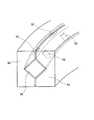
先ず、本実施形態に係るルーレット装置2の構成について図2を用いて説明する。図2は本実施形態に係るルーレット装置を示す斜視図である。 First, the configuration of the
図2に示すように、本実施形態に係るルーレット装置2は、ゲーム中にボール11が転動する転動領域を有するルーレット盤12と、ルーレット盤12をルーレットゲーム機1内部で支持する支持台13と、周囲の空気を取り込むとともに所定圧力に圧縮するコンプレッサ14と、コンプレッサ14により圧縮した空気を送るエアチューブ15、16と、各エアチューブ15、16の中間点にそれぞれ設けられエアチューブ15、16を流れる空気の圧力を調整する第1開閉弁17、第2開閉弁18とから基本的に構成されている。 As shown in FIG. 2, the
また、ルーレット盤12は、支持台13に固定される枠体21と、枠体21の内側に固定支持された中央固定部22と、中央固定部22の周囲に設けられた円環形状の回転可動部20と、から基本的に構成されている。そして、回転可動部20上面には凹状のボール収納部23が周方向に多数(本実施形態では38個)形成されている。ボール収納部23は、略三角形状の仕切壁23A(図6参照)によって仕切られ、更に、各ボール収納部23の外方向における回転可動部20の上面には、各ボール収納部23と対応するように図形文字としての「0」、「00」、「1」〜「36」の各数字が表示された番号表示板24が形成されている。尚、ルーレット盤12の詳細については後述する。 The
また、支持台13は金属製の柱を複数本組み合わせることにより形成された略長方形状を有する台であり、上面の角部に計4箇所設けられた固定具41よりルーレット盤12を所定の高さに固定している。 The
また、コンプレッサ14は、支持台13に形成された内部空間に配置され、周囲の空気を取り込むとともに取り込んだ空気を所定圧力(本実施形態では1Mpa)に圧縮する装置である。また、本実施形態に係るコンプレッサ14は、圧縮した空気を吐出する吐出ノズル42を備えており、吐出ノズル42にはエアチューブ15及びエアチューブ16が接続されている。 The
エアチューブ15は、コンプレッサ14により圧縮された空気をルーレット盤12の中央固定部22に形成された固定吐出口33へと搬送する為のチューブであり、その中間点には第1開閉弁17が設けられている。また、エアチューブ16は、コンプレッサ14により圧縮された空気をルーレット盤12に形成された回転吐出口36へと搬送する為のチューブであり、その中間点には第2開閉弁18が設けられている。 The
また、第1開閉弁17及び第2開閉弁18は、電磁バルブであって、開弁時間を調整することができる構造のものである。また、第1開閉弁17及び第2開閉弁18はルーレットゲーム機1全体の制御を行う後述のメイン制御用CPU80に接続されており(図11参照)、メイン制御用CPU80はROM81に予め記憶されたプログラムに従って後述のように開閉時間を制御する。それにより、固定吐出口33及び回転吐出口36から吐出される空気圧を調整し、ルーレット盤12上において、ボール11を転動させ、所定時間経過後にボール収納部23に収納させる一連の動作を行う。 Moreover, the 1st on-off
また、ルーレット装置2がルーレットゲーム機1に設置される際には、ルーレット盤12の上方全体が半球状の透明アクリル製のカバー部材25により覆われる(図1参照)。それにより、ゲームの際にルーレット盤12上を転動するボール11がルーレット盤12より外へ飛び出さないように保持することができる。また、異物等がルーレット盤12内に侵入することを防止し、不正行為等が行われないようにする。 Further, when the
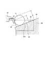
続いて、本実施形態に係るルーレット盤12について図3乃至図5を用いて詳細に説明する。図3は本実施形態に係るルーレット装置2を示す平面図、図4は図3の線A−Aでルーレット装置を切断した矢視断面図、図5は図4の特にボール収納部23付近を拡大して示した模式図である。 Next, the
ここで、ルーレット盤12は、前記したように支持台13に固定される枠体21と、枠体21の内側に固定支持された中央固定部22と、中央固定部22の周囲に設けられた円環形状の回転可動部20と、から基本的に構成されている。そして、図4に示すように回転可動部20は中央固定部22に対してクロスボールベアリング26を介して回転可能に支持されており、ルーレット装置2内部に設けられた駆動モータ34によって、ボール11の発射準備開始時からボール11がボール収納部23に収納されて所定時間経過するまでの間、枠体21に対して所定方向(例えば反時計回り方向)に所定速度(例えば5.005rpmや16.683rpm)で回転される(図14参照)。
また、特にベット期間終了後においてボール11を発射する際には、現在ボール11が収納されたボール収納部23が、中央固定部22に固定された固定吐出口33の正面位置にくるように回転可動部20を回転させる。一方、ボール転動終了後においてボール11が収納されたボール収納部23を検出する際には、現在ボール11が収納されたボール収納部23が、中央固定部22に固定された後述のボール検出センサ44の正面を通過するように回転可動部20を回転させる。尚、回転可動部20の具体的な回転駆動機構及び回転動作に関しては後に詳細に説明する。Here, the
In particular, when the
また、枠体21の外周縁部にはバンク通路29が周設されている。バンク通路29は、ルーレット盤12において転動するボール11の遠心力に抗してガイドし、ボール11を円周軌道を描いて転動させる通路である。また、バンク通路29は垂直方向に立設された案内壁30によって、ルーレット盤12に対して無端状に形成されており、更に、その外周部にあたる上端にはバンク通路29と連続して壁部31が形成されている。壁部31は、バンク通路29上を回転運動するボール11がルーレット盤12より外へと飛び出さないように内側に付勢する部材である。 A
そして、固定吐出口33から吐出された空気によって転動が開始され、回転吐出口36より吐出された空気によって周方向に加速力を付与されたボール11は、徐々にスピードを上昇させバンク通路29に沿って回転運動する。一方、回転吐出口36からの空気の吐出が停止されると、ボール11は回転速度が弱まり遠心力を失い、傾斜面28を転がり落ちてルーレット盤12の内側へと向かい、回転する回転可動部20に至る。
そして、回転可動部20に転がって来たボール11は、回転する回転可動部20の番号表示板24上を通っていずれかのボール収納部23に納まり、ボール11が収容されたボール収納部23に対応する番号表示板24に記載された数字が当選番号となる。Rolling is started by the air discharged from the fixed
Then, the
また、図5に示すようにボール収納部23の傾斜面28に対する深さLは、ボール11の直径Dよりも浅くなるように形成されている。前記したように、ボール収納部23は仕切壁23Aによって周方向に計38個に仕切られたボール11を収納する空間である。そして、ボール収納部23の深さLはボール11の直径Dより浅くなるように構成されているので、図5に示すように、ボール11がボール収納部23に収納された際に、ボール収納部23内にボール11が埋没されてしまう虞がなく、ゲーム中にボール収納部23内に収納されたボール11の位置を遊技者が容易に確認することが可能である。従って、遊技性が向上する。
また、ボール収納部23とバンク通路29とは、ボール収納部23よりバンク通路29へと所定の傾斜角度で上昇する一の傾斜面28により連続して形成されているので、遊技者はボール収納部23に収納されたボール11の確認が容易となる。Further, as shown in FIG. 5, the depth L of the
Further, since the
また、本実施形態に係るルーレット盤12が備えるボール収納部23は、メンテナンス等の作業を容易に行う為に回転可動部20に対して取り外し可能に設けられている。そして、ボール収納部23と回転可動部20はボール収納部23の底面に対して取り付けられたビス38によって固定される。
ここで、ビス38が取り付けられることによって、ボール収納部23の底面は凸状の形状を有することとなり、ボール11の転動態様をより多様化することが可能となるが、一方でビス38を取り付けたボール収納部23へのボール11の進入が妨害され、ボールの落下するボール収納部に偏りが生じる虞がある。しかしながら、本実施形態に係るルーレット盤12では、全てのボール収納部23の底面に対して計38箇所にビス38を取り付けているので、ボール11の転動態様を多様化することができるとともに、特定のボール収納部23の底面のみに対してビス38を取り付けている場合と比較して、ボール11がボール収納部23へと落下する際に、より偏りなく落下させることが可能である。Further, the
Here, when the
次に、ルーレット盤12の中央固定部22に設けられた固定吐出口33について図3乃至図6を用いて説明する。ここで、本実施形態に係るルーレット装置2は、遊技中において回転駆動されない中央固定部22にコンプレッサ14からの圧縮空気を吐出する固定吐出口33が設けられている。 Next, the fixed
固定吐出口33は、図3及び図4に示すように中央固定部22の特に回転可動部20に対向する外周縁に固定板27によって固定支持されている。そして、ルーレット装置2の下方に設けられたコンプレッサ14によって、所定圧力(例えば、1Mpa)に圧縮した空気をエアチューブ15を通してルーレット盤12へと搬送する。
一方、各ボール収納部23を仕切壁23Aとともに形成する内側壁37には、円形状に形成された空気通過孔35が形成されている。本実施形態では「0」、「00」、「1」〜「36」の各数字に対応した38個のボール収納部23が形成されており、従って空気通過孔35は計38箇所に形成されている。そして、図6に示すように固定吐出口33の正面に位置するボール収納部23(図6では番号「21」のボール収納部)は、固定吐出口33より吐出された空気が空気通過孔35及びボール収納部23を介してルーレット盤12の外周縁部に設けられたバンク通路29に向かって放射される。そして、吐出された空気の空気圧によって、ボール収納部23内に収納されているボール11は、傾斜面28の傾斜に抗してバンク通路29方向へと転動を開始する。As shown in FIGS. 3 and 4, the fixed
On the other hand, a circular
続いて、ルーレット盤12においてボール11を転動させる転動手段の一つである回転吐出口36について図7を用いて説明する。図7は本実施形態に係るルーレット装置2のバンク通路29付近を拡大して示した斜視図である。ここで、本実施形態に係るルーレット装置2は、前記固定吐出口33によって打ち出されたボール11をルーレット盤12上で転動させる際に、その動力源として圧縮された空気の空気圧を用いる。 Next, the
回転吐出口36は、図7に示すようにバンク通路29を構成する案内壁30に所定間隔(本実施形態では45度間隔)に形成されている。また、回転吐出口36は、バンク通路29の周方向、即ち、ルーレット盤12の接線方向に向けて形成されており、それぞれの回転吐出口36より吐出された空気はルーレット盤12のバンク通路29に沿って時計回り方向に流れる空気の層を作り出す(図20参照)。 As shown in FIG. 7, the
一方、回転吐出口36が形成された案内壁30の裏側面には円環状の回転用エアパイプ39が設置されている。回転用エアパイプ39は、エアチューブ16と接続されており、エアチューブ16から搬送された空気が回転用エアパイプ39内に流入され、8箇所に設けられた回転吐出口36より一斉に吐出される。それによって、前記ボール打出装置43より打ち出されてバンク通路29へと転動したボール11は、バンク通路29に沿って環状に流れる空気の層により時計回り方向に転動を開始する。
また、回転吐出口36からの空気の吐出を停止させると、バンク通路29に沿って形成されていた空気の層は消滅し、ボール11は回転速度が徐々に弱まり遠心力を失う。その後、傾斜面28の傾斜に沿って転がり落ちてルーレット盤12の内側へと向かい、回転する回転可動部20に至る。そして、回転可動部20に形成されたボール収納部23のいずれかに収納される。それにより、ルーレット装置2による当選番号の決定がなされ、ルーレットゲーム機1は決定された番号と、遊技者がベットしたベット情報に基づいて、メダルの払い出しを行って当該ゲームを終了する。
更に、その後に再び固定吐出口33より空気を吐出させると、ボール収納部23内に収納されたボール11は再び転動を開始し、次回のゲームをボール11を回収することなく連続して行うことが可能となる。On the other hand, an annular
Further, when the discharge of air from the
Further, when air is discharged again from the fixed
以上より、本実施形態に係るルーレット装置2では、ボール11をルーレット盤12より回収することなく、固定吐出口33及び回転吐出口36より吐出する空気の空気圧によってボール11に力を付加し、転動とボール収納部23への収納とを繰り返し行うことが可能となる。従って、ボール11を回収する為の可動部等や発射装置等の複雑な機構を必要とすることなく、メンテナンス作業が容易となるとともに装置のコストダウンが可能である。
また、ボール11を回収する為の可動部等や発射装置等の複雑な機構を必要としないので、ボール収納部23の深さLをボール11の直径Dより浅くすることができる(図5参照)。それにより、図4に示すように、ルーレット盤12の高さhを低くすることが可能となる。従って、ボール11を確認する為のルーレット装置2の視野角αを広くすることが可能であり、遊技者のボールの確認作業が容易となり、遊技性が向上する。
更に、ボール収納部23とバンク通路29とは、ボール収納部23よりバンク通路29へと所定の傾斜角度で上昇する一の傾斜面28により連続して形成されているので、遊技者はボール収納部23に収納されたボール11の確認が容易となる。As described above, in the
Further, since a complicated mechanism such as a movable part for collecting the
Furthermore, since the
次に、ルーレット盤12の中央固定部22に設けられたボール検出センサ44等の各種センサについて図3及び図8を用いて説明する。図8は図3の線B−Bでルーレット装置を切断した矢視断面図である。
ここで、本実施形態に係るルーレット装置2は、遊技中において回転駆動されない中央固定部22に対して、固定吐出口33とともに、ボール11が収納されたボール収納部23を検出するボール検出センサ44が設けられている。Next, various sensors such as the
Here, the
ボール検出センサ44は、図3及び図8に示すように中央固定部22の特に回転可動部20に対向する外周縁に固定板27によって固定支持されている。ここで、ボール検出センサ44は、反射型の光センサであり、赤外線を発光する発光素子と受光する受光素子とから構成されている。そして、所定距離内に障害物が存在する場合に、その存在と位置とをそれぞれ検出することが可能となっている。従って、ボール検出センサ44の正面に位置するボール収納部23内の所定位置(例えば、距離3cmの位置)に収納されたボール11を空気通過孔35を介して検知することができる。尚、ボール検出センサ44は透過型の光センサでも良く、その際には中央固定部22に受光素子を設置し、且つその対向するバンク通路29の位置に発光素子を設置する。それによって、発光素子と受光素子の間に位置するボール収納部23にボール11が存在する場合にそれを検知することが可能となる。 As shown in FIGS. 3 and 8, the
また、中央固定部22には、ボール検出センサ44の他に、原点センサ57及び回転センサ58が設けられている。ここで、原点センサ57及び回転センサ58は、ボール検出センサ44及び固定吐出口33と同様に、回転可動部20に対向する外周縁に固定板27によって固定支持されている。 In addition to the
原点センサ57は、原点センサ57の正面に位置するボール収納部23が、原点(基準点)に対して相対的にどの位置にあるボール収納部23なのかを検出するセンサである。また、回転センサ58は、回転可動部20が回転しているか否かを検出するセンサである。
具体的には、原点センサ57は、回転センサ58によって回転可動部20が回転していることを検出している間において、各ボール収納部23の内側壁37の裏側(原点センサ57に対向する側)に対して付設された凹凸形状を有する識別プレート(図示せず)の凹凸を検知することによって、現在原点センサ57の正面に位置するボール収納部23が、原点である「0」に対応付けられたボール収納部23に対して相対的にどの位置にあるのかを常時検出する。例えば、図3に示す時点では原点センサ57の正面に位置するボール収納部23(「35」が対応付けられたボール収納部)が、「0」に対応付けられたボール収納部23から右方向に36番目に位置するボール収納部23であることを検出する。The
Specifically, while the
従って、原点センサ57によれば、前記ボール検出センサ44によってボール11が検出されたタイミングにおいて、原点センサ57の正面に位置するボール収納部23が「0」に対応付けられたボール収納部23から相対的にどの位置にあるのかを検出することが可能となる。そして、その検出結果に基づいてボール検出センサ44によってボール11が検出されたボール収納部23が「0」に対応付けられたボール収納部23から相対的にどの位置にあるのかを算出することが可能となる。それにより、ボール11が検出されたボール収納部23に対応付けられた番号(「0」、「00」、「1」〜「36」)、即ち当選番号を特定することができる(図16のS20)。尚、原点(基準点)は「0」に対応付けられたボール収納部23である必要はなく、他のボール収納部23であっても良い。 Therefore, according to the
また、遊技開始時にボール11を発射する際においては、前回のゲームの当選番号と、原点センサ57の正面に位置するボール収納部23が「0」に対応付けられたボール収納部23から相対的にどの位置にあるのかの検出結果とに基づいて、ボール11が収納されているボール収納部23が固定吐出口33の正面の位置にあるか否かを判定することが可能となる。そして、判定結果に基づいて駆動モータ34を制御することにより、固定吐出口33の正面(固定吐出口33によりボール11が打ち出し可能な位置)にボール11が収納されたボール収納部23を位置させ、ボール11の発射が可能となる(図16のS6〜S8)。 Further, when the
以上より、本実施形態に係るルーレットゲーム機1では、ボール11がボール収納部23に収納された後に、回転可動部20を少なくとも1/3周以上回転させることによって、全てのボール収納部23の前をいずれかのボール検出センサ44が通過することとなる。そして、ボール11が検出されたタイミングでの原点センサ57の検出結果が後述のメイン制御用CPU80(図11参照)に送信される。その結果に基づき、メイン制御用CPU80は当選番号の判定を行う。
また、ボール発射時においては、固定吐出口33の正面位置(固定吐出口33によりボール11が打ち出し可能な位置)に前回のゲームにおける当選番号のボール収納部23が位置するように後述の駆動モータ34を制御し、第1開閉弁17を開放することによりボール収納部23からのボール11の発射が可能となる。As described above, in the
Further, when the ball is fired, a drive motor described later is arranged so that the
次に、ルーレット盤12の中央固定部22に対する回転可動部20の回転駆動機構について図4及び図9を用いて説明する。ここで、図9は本実施形態に係るルーレット装置2において、中央固定部22に対して回転可動部20を回転可能に支持するクロスボールベアリング26を所定位置で切断して示した模式図である。 Next, the rotational drive mechanism of the rotary
図4に示すように、枠体21の底面板21Aには駆動モータ34が固定されている。ここで、駆動モータ34は、パルス信号を与えることでフィードバック無しに決められたステップ単位で回転可能なステッピングモータである。従って、駆動モータ34に与えるパルス信号の回数と周期によってその回転角度と回転速度が決定され、更に、パルス信号の停止によりその時点での回転角を保持して停止する。 As shown in FIG. 4, a
また、駆動モータ34には駆動軸46を介して駆動ローラ47が取り付けられており、更に駆動ローラ47は回転可動部20の側面20Aに当接されている。従って、駆動モータ34が駆動されると、その回転に伴って駆動ローラ47も回転し、更に駆動ローラ47との摩擦によって回転可動部20が中央固定部22に対して回転することとなる。また、駆動ローラ47は「コ」の字形状を有するローラケース48内に収納されており、更にローラケース48は駆動ローラ47の外周側に設けられた付勢部材49によって側面20A方向に一定の力で付勢されている。従って、駆動ローラ47と回転可動部20の側面20Aとは常に適度の圧力に基づいて当接された状態となり、駆動ローラ47に必要以上の負荷がかかったり、空転する虞が無い。 A
また、図4及び図9に示すように中央固定部22の固定側内壁部50と、固定側内壁部50に対向する回転可動部20の可動側内壁部51とはクロスボールベアリング26によって接続されている。 Further, as shown in FIGS. 4 and 9, the fixed-side
ここで、クロスボールベアリング26は、断面略四角形状を有する円環状の部材であり、図9に示すように、その4つの各面にはベアリング52が30〜40箇所にそれぞれ取り付けられている。それにより、枠体21に固定された固定側内壁部50に対して可動側内壁部51が自在に可動することが可能となり、中央固定部22に対して回転可動部20が回転可能に支持されることとなる。 Here, the
従って、パルス信号により駆動された駆動モータ34の回転方向と回転角度とに基づいて、回転可動部20を中央固定部22に対して所定角度回転させることが可能となり、それに伴ってボール打出装置43及びボール検出センサ44の正面に位置するボール収納部23を任意のボール収納部23に変更する。それにより、ボール11が収納されたボール収納部23の検出、並びに収納されているボール11の発射が可能となる。また、駆動モータ34は、モータ駆動回路55を介してメイン制御用CPU80に接続されており(図11参照)、ROM等に記憶されたプログラムに基づいて後述のようにその駆動が制御される(図13、図14参照)。 Therefore, based on the rotation direction and rotation angle of the
次に、本実施形態に係るコントロール部6及び画像表示装置7の構成について説明する。
コントロール部6は、図1に示すように画像表示装置7の側部に設けられ、遊技者により操作される各ボタンが配置されている。具体的には、サテライト4に対向する位置から見て左側からBET確定ボタン62、払い戻し(CASHOUT)ボタン63、ヘルプ(HELP)ボタン64が配置されている。Next, configurations of the
As shown in FIG. 1, the
BET確定ボタン62は、後述する画像表示装置7によるベット操作の後にベットを確定する際に押下されるボタンである。そして、ベットが確定され、且つ、遊技中に前記ルーレット装置2においてボール11が納まったボール収納部23に対応する番号表示板24に記載された番号にベットしていた場合に当選となる。当選した場合には、ベットしたチップの枚数に応じたクレジットが、遊技者の現在所有するクレジットに加算される。尚、ベット操作については後に詳細に説明する。 The
払い戻しボタン63は、通常、ゲーム終了時に押下されるボタンであり、払い戻しボタン63が押下されると、ゲーム等によって獲得した現在遊技者が所有するクレジットに応じたメダル(通常は1クレジットに対してメダル1枚)がメダル払出口8から払い戻される。 The payout button 63 is a button that is normally pressed at the end of the game. When the payout button 63 is pressed, a medal (usually for one credit) according to the credits owned by the current player acquired by the game or the like. 1 medal) is paid out from the
ヘルプボタン64は、ゲームの操作方法等が不明な場合に押下されるボタンであり、ヘルプボタン64が押下されると、その直後に画像表示装置7上に各種の操作情報を示したヘルプ画面が表示される。 The
一方、画像表示装置7はタッチパネル53が前面に取り付けられた所謂タッチパネル方式の液晶ディスプレイであり、液晶画面上に表示されたアイコンを指等で押圧することによりその選択が可能となっている。図10は遊技中に画像表示装置に表示される表示画面の一例を示した図である。 On the other hand, the
図10に示すように、ルーレットゲーム機1の遊技中において画像表示装置7には、テーブル式ベッティングボード60を有するBET画面61が表示される。そして、遊技者はBET画面61を操作することによって、手持ちのクレジットを使用してチップをベットすることができる。 As shown in FIG. 10, during the game of the
以下に、図10に基づいてBET画面61について説明する。BET画面61に表示されるテーブル式ベッティングボード60には、前記番号表示板24に表示された数字「0」、「00」、「1」〜「36」と同じ数字がマス目状に配列表示されている。また、「奇数の数字」、「偶数の数字」、「番号表示板の色の種類(赤又は黒)」、「一定の数字範囲(例えば「1」〜「12」等)」を指定してチップをベットする為の特殊なBETエリアも同様にマス目状に配列されている。 The
そして、テーブル式ベッティングボード60の下方には画面左から順に、結果履歴表示部65、単位BETボタン66、払い戻し結果表示部67、クレジット数表示部68が表示されている。 A result
結果履歴表示部65は、前回までのゲーム(ここで、1ゲームは、各サテライト4において遊技者がベットを行い、ボール11がボール収納部23に落下し、当選番号に基づいてクレジットの払い出しが行われるまでの一連の動作をいう。)における当選番号の結果が一覧に表示される。その際、1ゲームが終了すると、新たな当選番号が上から追加して表示されていき、最大16ゲームの当選番号の履歴を確認することが可能となっている。 The result
また、単位BETボタン66は、遊技者が指定したBETエリア(番号及びのマークのマス目上、若しくはマス目を形成するライン上)にベットする為のボタンである。単位BETボタンは1BETボタン66A、5BETボタン66B、10BETボタン66C、100BETボタン66Dの四種類からなる。
遊技者は、先ず、ベットするBETエリアを指等で画面を直接押すことにより、後述のカーソル70でBETエリアを指定する。その状態で、1BETボタン66Aを押下すると、遊技者はチップを1枚毎(1BETボタン66Aを指等で押す毎に「1」→「2」→「3」→・・・の順にベット枚数が増加)にベットする。一方、10BETボタン66Cを押下すると、チップを10枚単位(10BETボタン66Cを指等で押す毎に「10」→「20」→「30」→・・・の順にベット枚数が増加)でベットすることが可能である。尚、5BETボタン66B、100BETボタン66Dの操作も同様である。従って、多量のチップをベットする際にも、その操作を簡略化することができる。The
The player first designates a BET area with a cursor 70 (to be described later) by directly pressing the screen with a finger or the like in the BET area to bet. In this state, when the
また、払い戻し結果表示部67は、前回のゲームにおける遊技者のチップのベット枚数、及び払い戻しのクレジット数が表示される。ここで、払い戻しクレジット数よりベット枚数を引いた数が、前回のゲームにより遊技者が新たに獲得したクレジット数である。 The refund
更に、クレジット数表示部68は、現在の遊技者が所有するクレジット数が表示される。このクレジット数は、チップをベットした際にはそのベット枚数(チップ一枚につき1クレジット)に応じて減少する。また、ベットした番号が当選し、クレジットの払い戻しがなされた場合には、払い戻し枚数分のクレジット数が増加する。尚、遊技者が所有するクレジット数が0となった場合には、遊技終了となる。 Further, the credit
そして、テーブル式ベッティングボード60の上部には、BETタイマーグラフ69が設けられている。BETタイマーグラフ69は遊技者がベットすることが可能な残り時間を表示するグラフであり、ゲーム開始時より赤いグラフが徐々に右側に延び始める。そして、最も右側まで延びたときに現在のゲームにおけるベット可能な時間が終了する。また、各サテライト4において遊技者のベット期間が終了する5秒前、即ち、BETタイマーグラフ69が最も右側まで達する5秒前に前記固定吐出口33によってボール収納部23内のボール11を打ち出し、ボール11の転動を開始させる。 A
また、テーブル式ベッティングボード60上には、現在遊技者が選択しているBETエリアを示すカーソル70が表示される、また、現時点までにおいてベットしたチップの枚数とBETエリアを示すチップマーク71が表示され、チップマーク71上に表示された数字が、チップのベット枚数を示す。例えば、図10に示すように「18」のマスに置かれた「7」のチップマーク71は、番号「18」に7枚のチップをベットしていることを示している。このように1つ番号のみにベットする方法は「ストレート・アップ」と呼ばれるベット方法である。
また、「5」、「6」、「8」、「9」のマス目の交点に置かれた「1」のチップマーク71は、番号「5」、「6」、「8」、「9」の4つの番号をカバーして1枚のチップをベットしていることを示している。尚、このように4つ番号をカバーしてベットする方法は「コーナー・ベット」と呼ばれるベット方法である。On the table-
Further, the
他にベット方法としては、2つの番号の間のライン上に2つの番号をカバーしてベットする「スプリット・ベット」、番号の横一列(図10中、縦方向の一列)の端に3つの番号(例えば、「13」、「14」、「15」)をカバーしてベットする「ストリート・ベット」、番号「00」と「3」の間のライン上に「0」、「00」、「1」、「2」、「3」の5つの番号をカバーしてベットする「ファイブ・ベット」、番号の横二列(図3中、縦方向の二列)の番号の間に6つの番号(例えば、「13」、「14」、「15」、「16」、「17」、「18」)をカバーしてベットする「ライン・ベット」、「2to1」と書かれたマス目上で12個の番号をカバーしてベットする「コラム・ベット」、「1st12」、「2nd12」、「3rd12」と書かれたマス目上でそれぞれ12個の番号をカバーしてベットする「ダズン・ベット」がある。更に、テーブル式ベッティングボード60の最下段に設けられた6つのマス目を用いて、番号表示板の色(「赤」又は「黒」)、番号の奇数偶数、番号が18以下か19以上かによって18個の番号をカバーしてベットする方法がある。 Other betting methods include a “split bet” where two numbers are covered on a line between two numbers, and three at the end of a horizontal row of numbers (a vertical row in FIG. 10). A “street bet” that covers and bets numbers (eg, “13”, “14”, “15”), “0”, “00” on the line between numbers “00” and “3”, “Five bet” to bet covering five numbers “1”, “2”, “3”, six between the numbers in two horizontal rows of numbers (vertical two rows in FIG. 3) Covering numbers (eg, “13”, “14”, “15”, “16”, “17”, “18”) and betting “line bet”, “2to1” above the
前記のように構成されたBET画面61で遊技者がベットする際には、先ず、ベットを行うBETエリア(番号及びのマークのマス目上、若しくはマス目を形成するライン上)を画面上で指定して直接指により押圧する。その結果、カーソル70が指定したBETエリアに移動する。
その後、単位BETボタン66の各単位ボタン(1BETボタン66A、5BETボタン66B、10BETボタン66C、100BETボタン66D)を押下することにより、その単位数分のメダルが指定されたBETエリアにベットされる。例えば、10BETボタン66Cを4回、5BETボタン66Bを1回、1BETボタン66Aを3回押下すれば、合計48枚のメダルをベットすることができる。When a player places a bet on the
Thereafter, by depressing each unit button (
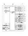
次に、本実施形態に係るルーレットゲーム機1の制御系に係る構成について図11に基づき説明する。図11はルーレットゲーム機の制御系を模式的に示すブロック図である。
図11に示すように、ルーレットゲーム機1は、メイン制御用CPU80、ROM81、及びRAM82を含むメイン制御部83と、メイン制御部83に接続されたルーレット装置2、及び12台のサテライト4(図1参照)と、駆動モータ34と、第1開閉弁17及び第2開閉弁18とから構成されている。尚、サテライト4の制御系に関しては後に詳細に説明する。Next, a configuration related to the control system of the
As shown in FIG. 11, the
メイン制御用CPU80は、各サテライト4から供給される入力信号等、並びに、ROM81、及びRAM82に記憶されたデータやプログラムに基づいて、各種の処理を行い、その結果に基づいてサテライト4に命令信号を送信することにより、各サテライト4を主導的に制御し、遊技を進行させる。更に、駆動モータ34を駆動させるとともに、ルーレット装置2に設けられたボール検出センサ44(図8参照)を制御し、ボール11が落下したボール収納部23の当選番号の判定を行う。そして、得られた当選番号と、各サテライト4から送信されたベット情報とに基づいて、ベットされたチップの当選判定を行い、各サテライト4において払い出されるクレジット数を計算する。 The
ROM81は、例えば、半導体メモリ等により構成され、ルーレットゲーム機1の基本的な機能を実現させるためのプログラムや、ルーレット装置2内の各装置、第1開閉弁17及び第2開閉弁18を制御するプログラム、駆動モータ34を制御するプログラム、回転可動部20の回転パターン(即ち、駆動手段の駆動制御パターン)を複数パターンから抽選する回転期間抽選テーブル99(図15参照)、BET画面61を用いた通常のルーレットゲームに対するオッズ(チップ一枚あたりの当選に対するクレジットの払い出し数)、各サテライト4を主導的に制御するためのプログラム等を記憶する。 The
一方、RAM82は、各サテライト4から供給されるチップのベット情報、ボール検出センサ44により判定されたルーレット装置2の当選番号、及びメイン制御用CPU80により実行された処理の結果に関するデータ等を一時的に記憶する。 On the other hand, the
また、メイン制御用CPU80には、エアチューブ15、16内の空気圧の調整を行う第1開閉弁17及び第2開閉弁18が接続されている。そして、第1開閉弁17を開くことによって、ボール収納部23に設けられた固定吐出口33より、コンプレッサ14(図2参照)で圧縮された空気を吐出させる。また、第2開閉弁18を開くことによって、バンク通路29に設けられた回転吐出口36よりコンプレッサ14で圧縮された空気を吐出させる。 The
また、メイン制御用CPU80には、ルーレット装置2に設けられたボール検出センサ44、原点センサ57及び回転センサ58が接続されている。ボール検出センサ44は、前記したように中央固定部22の3箇所に設けられており、正面に位置する当該ボール収納部23にボール11が収納されている場合に、その存在と対応付けられた番号を検知することができる。また、原点センサ57は、正面に位置する当該ボール収納部23の原点(「0」が対応付けられたボール収納部)に対する相対的な位置を検出することができる。また、回転センサ58は回転可動部20の回転の有無を検出することができる。そして、各センサの検出結果がメイン制御用CPU80に送信されることにより、メイン制御用CPU80は当選番号の判定を行う。 The
また、メイン制御用CPU80には、モータ駆動回路55を介して回転可動部20の回転駆動を行う駆動モータ34が接続されている。メイン制御用CPU80からモータ駆動信号がモータ駆動回路55に出力されると、駆動モータ34はモータ駆動回路55からのパルス信号が与えられ、そのパルス信号に基づいて所定の回転方向に所定回転数だけ回転駆動される。これにより回転可動部20が中央固定部22及び枠体21に対して所定方向(例えば、反時計回り方向)に所定角度(例えば、45度)だけ回転され、固定吐出口33の正面位置に任意のボール収納部23を配置することが可能となる。また、ROM81に記録された駆動モータ34の制御プログラムに従って所定速度で所定期間、回転可動部20を回転させることが可能となる。 Further, the
また、メイン制御用CPU80には、乱数を発生する乱数発生器85及び乱数サンプリング回路86が接続されている。乱数サンプリング回路86を介してサンプリングされた乱数は、後述のように回転期間抽選テーブル99を用いた回転可動部20の回転パターン(駆動モータ34の駆動制御パターン)の抽選に使用される。 The
更に、メイン制御用CPU80には、時間計測を行うタイマー84が接続されている。タイマー84の時間情報はメイン制御用CPU80に送信され、メイン制御用CPU80はタイマー84の時間情報に基づいて後述のように第1開閉弁17及び第2開閉弁の開閉と、駆動モータ34の駆動制御を行う。 Further, a
また、メイン制御用CPU80には、電光表示部77(図1参照)が接続されている。そして、LED等の発光手段の発光を制御することにより電飾による演出を行い、また電光表示部77に対して所定の文字等の表示を行う。更に、電光表示部77の特にJP額表示部78には、現在までに累積されているJPの額を表示させる。 The
次に、本実施形態に係るメイン制御部83のCPU80に接続されたサテライト4の制御系に係る構成について図12に基づき説明する。図12は本実施形態に係るサテライトの制御系を模式的に示すブロック図である。尚、12台設けられたサテライト4は基本的に同じ構成を有しており、以下には1台のサテライト4を例にして説明する。 Next, a configuration related to the control system of the
サテライト4は、図12に示すように、サテライト制御部90、及びいくつかの周辺装置機器により構成されている。サテライト制御部90は、サテライト制御用CPU91と、ROM92と、RAM93とからなっている。ROM92は、例えば、半導体メモリ等により構成され、サテライト4の基本的な機能を実現させるためのプログラム、その他サテライト4の制御上必要な各種のプログラム、データテーブル等が格納されている。また、RAM93は、サテライト制御用CPU91で演算された各種データ、遊技者の現在所有するクレジット数、遊技者によるチップのベット状況等を一時的に記憶しておくメモリである。 As shown in FIG. 12, the
また、サテライト制御用CPU91には、コントロール部6(図1参照)に設けられたBET確定ボタン62、払い戻しボタン63、ヘルプボタン64がそれぞれ接続されている。そして、サテライト制御用CPU91は各ボタンの押下等により出力される操作信号に基づき、対応する各種の動作を実行すべく制御を行う。具体的には、遊技者の操作が入力されたことを受けてコントロール部6から供給される入力信号、並びに、ROM92、RAM93に記憶されたデータやプログラムに基づいて、各種の処理を実行し、その結果を上述したメイン制御部83のメイン制御用CPU80に送信する。
一方、サテライト制御用CPU91は、メイン制御用CPU80からの命令信号を受信し、サテライト4を構成する周辺機器を制御し、サテライト4においてルーレットゲームを進行させる。また、サテライト制御用CPU91は、処理の内容によっては、遊技者の操作が入力されたことを受けてコントロール部6から供給される入力信号、及び、ROM92とRAM93とに記憶されたデータやプログラムに基づいて、各種の処理を実行し、その結果に基づいて、サテライト4を構成する周辺機器を制御し、サテライト4においてルーレットゲームを進行させる。なお、どちらの方法で処理を行うかについては、その処理の内容に応じて、処理ごとに設定される。例えば、当選番号に対するメダルの払い出し処理は前者であり、遊技者によるBET画面61のベット操作処理は後者の処理に該当する。The
On the other hand, the
また、サテライト制御用CPU91には、ホッパー94が接続されている。サテライト制御用CPU91からの命令信号により、ホッパー94は、所定枚数のメダルをメダル払出口8(図1参照)から払い出す。
更に、サテライト制御用CPU91には、液晶駆動回路95を介して画像表示装置7が接続されている。この点、液晶駆動回路95は、プログラムROM、画像ROM、画像制御CPU、ワークRAM、VDP(ビデオ・ディスプレイ・プロセッサ)及びビデオRAMなどで構成されている。そして、プログラムROMには、画像表示装置7での表示に関する画像制御用プログラムや各種選択テーブルが格納されている。また、画像ROMには、例えば、画像表示装置7で表示される画像を形成するためのドットデータが格納されている。また、画像制御CPUは、サテライト制御用CPU91で設定されたパラメータに基づき、プログラムROM内に予め記憶された画像制御プログラムに従い、画像ROM内に予め記憶されたドットデータの中から画像表示装置7に表示する画像の決定を行うものである。また、ワークRAMは、前記画像制御プログラムを画像制御CPUで実行するときの一時記憶手段として構成される。また、VDPは、画像制御CPUで決定された表示内容に応じた画像を形成し、画像表示装置7に出力するものである。尚、ビデオRAMは、VDPで画像を形成するときの一時記憶手段として構成される。A
Further, the
また、画像表示装置7の前面には、前記したようにタッチパネル53が取り付けられており、タッチパネル53の操作情報はサテライト制御用CPU91に対して送信される。タッチパネル53では、前記BET画面61において遊技者のチップのベット操作が行われる。具体的には、BETエリアの選択、単位BETボタン66の操作等においてタッチパネル53の操作が行われ、その情報がサテライト制御用CPU91に送信さる。そして、その情報に基づいてRAM93に現在の遊技者のベット情報(BET画面61において指定したBETエリア、並びにベットしたチップの枚数)が随時記憶される。更に、そのベット情報はメイン制御用CPU80に対して送信され、RAM82のベット情報記憶エリアに記憶される。 Further, the
更に、音出力回路96及びスピーカ9がサテライト制御用CPU91に接続されており、スピーカ9は、音出力回路96からの出力信号に基づき各種演出を行う際に各種の効果音を発生するものである。 Furthermore, a
また、サテライト制御用CPU91にメダルセンサ97が接続されている。メダルセンサ97はメダル投入口5(図1)から投入されたメダルを検出するとともに、投入されたメダルを演算し、その結果をサテライト制御用CPU91に対して送信する。そして、サテライト制御用CPU91は、送信された信号に基づいてRAM93に記憶された遊技者のクレジット数を増加させる。 A
次に、図13に基づいてROM81に記憶された制御プログラムに基づく第1開閉弁17及び第2開閉弁18の開閉のタイミングと、駆動モータ34の駆動制御について示す。図13は第1開閉弁17及び第2開閉弁18の開閉のタイミングと駆動モータ34の駆動制御とを示した説明図である。 Next, the opening / closing timings of the first on-off
図13に示すように、ゲームが開始されると、先ず遊技者による各サテライト4でのチップのベットを行うベット期間が開始される。そして、ベット期間が終了する10秒前になると、前回の当選番号と原点センサ57の検出結果とに基づいてボール11が収納されているボール収納部23の位置が特定され、固定吐出口33の正面にそのボール収納部23が位置するまで駆動モータ34を所定の第1回転速度で駆動し、回転可動部20を所定の回転速度(例えば、4rpm)で中央固定部22に対して回転させる。その後、ベット期間が終了する5秒前になると、メイン制御用CPU80は第1開閉弁17を所定時間(本実施形態では2秒)開放する。同時に、第2開閉弁18を開放し、ルーレット盤12のバンク通路29に沿って流れる環状の空気の層を作り出す(図20参照)。そして、前記固定吐出口33からの空気圧によってバンク通路29方向へと転動されたボール11が、空気の流れに従ってバンク通路29を時計回り方向に回転する。それと同時に、駆動モータ34を所定の第2回転速度及び第3回転速度で所定期間駆動し、回転可動部20を所定の回転速度(例えば、5.005rpm及び16.683rpm)で中央固定部22に対して回転させる。ここで、ボール11の発射後からボール11がボール収納部23に落下するまでの駆動モータ34の駆動制御は乱数値を用いた内部抽選によってゲーム毎に変動する。その詳細については後に図14を用いて説明する。
その後、第2開閉弁18の開放から所定時間(本実施形態では20秒)経過した際に、メイン制御用CPU80は第2開閉弁18を閉鎖する。それにより、回転吐出口36から吐出されていた空気が止まり、ボール11の回転速度が徐々に弱まる。次第にボール11が描く円は徐々に小さくなり、最後には遠心力を失って傾斜面28の斜面を転がり落ち、ボール収納部23に納まる。そして、第2開閉弁18を閉鎖した後に、徐々に駆動モータ34の回転速度を減衰させ、回転可動部20の回転速度を遅くする。その間において、ボール検出センサ44、原点センサ57及び回転センサ58の各センサにより当選番号の判定を行う。更に、判定された当選番号に従ってメダルの払い出しを行う。以上により、1ゲームが終了する。更に、続けてゲームを開始する場合には、同様にサテライト4のベット期間が開始され、ベット期間の終了する10秒前になると、メイン制御用CPU80は第1開閉弁17及び第2開閉弁18を開放する。尚、当該第1開閉弁17及び第2開閉弁18の開閉と駆動モータ34の駆動制御に基づくルーレットゲーム処理プログラムについては後にフローチャートを用いて詳細に説明する(図16参照)。As shown in FIG. 13, when a game is started, first, a betting period in which a player bets chips on each
Thereafter, when a predetermined time (20 seconds in the present embodiment) has elapsed since the opening of the second on-off
次に、図14に基づいて、特にボール11の発射後からボール11がボール収納部23に落下するまでの回転可動部20の回転態様及び駆動モータ34の駆動制御について説明する。図14はボール11の発射後からボール11がボール収納部23に落下するまでの駆動モータ34による回転可動部20の回転態様について示した説明図である。 Next, with reference to FIG. 14, the rotation mode of the rotary
図14に示すように、ボール11の発射後からボール11がボール収納部23に落下するまでの回転可動部20の回転期間は基本的に7つの期間により構成されており、ボールが発射されてからT1が経過するまでの第1期間(図14の(1)に相当)は回転可動部20の回転速度が0rpm、即ち停止状態となるように駆動モータ34が制御される。
また、第1期間が終了してからT2が経過するまでの第2期間(図14の(2)に相当)は回転可動部20の回転速度が0rpmから5.005rpmまで時間に比例して増加するように駆動モータ34が制御される。
また、第2期間が終了してからT3が経過するまでの第3期間(図14の(3)に相当)は回転可動部20の回転速度が5.005rpmとなるように駆動モータ34が制御される。
また、第3期間が終了してからT4が経過するまでの第4期間(図14の(4)に相当)は回転可動部20の回転速度が5.005rpmとなるように駆動モータ34が制御される。
また、第4期間が終了してからT5が経過するまでの第5期間(図14の(5)に相当)は回転可動部20の回転速度が5.005rpmから16.683rpmまで時間に比例して増加するように駆動モータ34が制御される。
また、第5期間が終了してからT6が経過するまでの第6期間(図14の(6)に相当)は回転可動部20の回転速度が16.683rpmとなるように駆動モータ34が制御される。
また、第6期間が終了してからT7が経過するまで(ボール11がボール収納部23に落下するまで)の第7期間(図14の(7)に相当)は回転可動部20の回転速度が16.683rpmとなるように駆動モータ34が制御される。As shown in FIG. 14, the rotation period of the rotary
Further, in the second period (corresponding to (2) in FIG. 14) from the end of the first period until T2 elapses, the rotational speed of the rotary
Further, in the third period (corresponding to (3) in FIG. 14) from the end of the second period until T3 elapses, the
Further, in the fourth period (corresponding to (4) in FIG. 14) from the end of the third period until T4 elapses, the
Further, in the fifth period (corresponding to (5) in FIG. 14) from the end of the fourth period until T5 elapses, the rotational speed of the rotary
Further, in the sixth period (corresponding to (6) in FIG. 14) from the end of the fifth period until T6 elapses, the
Further, the rotation speed of the rotary
そして、前記第1乃至第7期間の内、第1乃至第3期間、第5期間及び第7期間の時間(T1〜T3、T5、T7)が常に固定となっている一方、第4期間及び第6期間の時間(T4、T6)は可変となっている。具体的には、第4期間及び第6期間の時間(T4、T6)は、乱数値を用いた内部抽選の抽選結果と、ボール打ち出し時のボール収納部23の配置に基づく補正によってゲーム毎に決定される。従って、ゲームを行う度に回転可動部20の回転パターンが変化することとなり、ボール11が落下するボール収納部23の偏りを無くすことが可能となる。 Among the first to seventh periods, the times (T1 to T3, T5, T7) of the first to third periods, the fifth period, and the seventh period are always fixed, while the fourth period and The time (T4, T6) of the sixth period is variable. Specifically, the time of the fourth period and the sixth period (T4, T6) is determined for each game by correction based on the lottery result of the internal lottery using random values and the arrangement of the
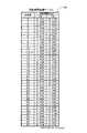
以下に、第4期間及び第6期間の時間(T4、T6)の決定手順について説明する。図15は第4期間の時間(T4)及び第6期間の時間(T6)を抽選する回転期間抽選テーブル99について示した図である。 Hereinafter, a procedure for determining the times (T4, T6) of the fourth period and the sixth period will be described. FIG. 15 is a diagram showing the rotation period lottery table 99 for lottering the fourth period time (T4) and the sixth period time (T6).
図15に示すように、T4及びT6の値は予め計38パターンの組合せが設定されており、乱数サンプリング回路86(図11参照)により0〜37の範囲でサンプリングされた乱数値に基づいて一の組合せが選択される。例えば、サンプリングされた乱数値が「5」であった場合には、T4が0.776sec、T6が4.500secの組合せが選択される。また、サンプリングされた乱数値が「30」であった場合には、T4が4.156sec、T6が1.120secの組合せが選択される。
また、この38パターンの組合せは、ボール11落下時の回転可動部20の回転数が1/38回転ずつ異なるように設定されており、関連付けられた乱数値が1大きい回転期間は1小さい回転期間より、回転可動部20がボール収納部23の一個分だけボール落下時までにより多く回転することとなる。
更に、可変期間である第4期間、第6期間の合計(T4+T6)は抽選結果に関わらず常に5.276secであるので、ルーレットゲーム機1の全体の制御に対して駆動制御パターンの変動が影響を及ぼす虞がない。As shown in FIG. 15, a total of 38 pattern combinations are set in advance for the values of T4 and T6, and one is based on the random number values sampled in the range of 0 to 37 by the random number sampling circuit 86 (see FIG. 11). Is selected. For example, when the sampled random number value is “5”, a combination of T4 of 0.776 sec and T6 of 4.500 sec is selected. When the sampled random number value is “30”, the combination of T4 of 4.156 sec and T6 of 1.120 sec is selected.
In addition, the 38 pattern combinations are set such that the rotation speed of the rotary
Furthermore, since the total of the fourth period and the sixth period (T4 + T6), which is a variable period, is always 5.276 sec regardless of the lottery result, the fluctuation of the drive control pattern affects the overall control of the
また、本実施形態に係るルーレット装置2では、サンプリングされた乱数値に基づいて選択されたT4及びT6の値は、ボール打ち出し時のボール収納部23の配置に基づいて補正される。具体的には、前記ボール検出センサ44及び原点センサ57(図3参照)によって前回遊技終了時にボール11が収納されているボール収納部23が、原点である「0」に対応付けられたボール収納部23に対して相対的にどの位置にあるのかが検出され、原点である「0」に対応付けられたボール収納部23に対して右方向にn番目に位置するボール収納部23に収納されている場合には、前記サンプリングされた乱数値にnを加えた乱数値(38以上になった場合には38を引いた乱数値)を補正乱数値として設定し、補正乱数値と回転期間抽選テーブル99に基づいて最終的なT4及びT6の値を決定する。 Further, in the
ここで、本実施形態に係るルーレット装置2では、前記したように固定吐出口33によるボール打ち出し時において固定吐出口33の正面にボール11が収納されたボール収納部23を位置させる。したがって、nの値はボール打ち出し時における、原点である「0」に対応付けられたボール収納部23と固定吐出口33との相対的な位置関係を特定する数値でもあり、上記補正を行うことによって、ボール打ち出し時においてボール収納部23がどのような配置をしていた場合であっても(言い換えれば、ボール11が前回のゲームにおいてどのボール収納部23に落下した場合であっても)、補正を行う前のサンプリングされた乱数値と回転期間抽選テーブル99に基づいて決定された位置にボール落下時の回転可動部20を位置させることが可能となる。
従って、ボール落下時の回転可動部20の位置、即ちボール落下時のボール収納部23の配置がサンプリングされた乱数値に完全に依存することが可能となり、サンプリングされた乱数値が異なる数値であっても、ボール落下時に回転可動部20が同じ位置となる事態を防止することが可能となる。それにより、ボール11をより偏りなくボール収納部23に落下させることができる。Here, in the
Accordingly, the position of the rotary
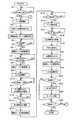
続いて、本実施形態に係るルーレットゲーム機1におけるゲーム処理プログラムについて図16に基づき説明する。図16は本実施形態に係るルーレットゲーム機1におけるルーレットゲーム処理プログラムのフローチャートである。尚、以下に図16及び図17にフローチャートで示される各プログラムはルーレットゲーム機1が備えているROM81やRAM82に記憶されており、メイン制御用CPU80により実行される。 Next, a game processing program in the
先ず、ステップ(以下、Sと略記する)1において、メイン制御用CPU80は、遊技者によるメダル又は貨幣が投入されたか否かを判断する。本実施形態に係るルーレットゲーム機1では、いずれかのサテライト4でメダル投入口5にメダル又は貨幣が投入されると、メダルセンサ97がその旨を検出しサテライト制御用CPU91に送信される。その後、更にサテライト4よりメイン制御部83にメダル投入信号が送られる。それにより、メイン制御用CPU80は遊技者によるメダル又は貨幣の投入を判断する。メダル又は貨幣の投入がない場合(S1:NO)には、投入されるまで待機される一方、メダル又は貨幣の投入があった場合(S1:YES)には、S2へ移行する。尚、メダル又は貨幣の投入があった場合、サテライト制御部90では、投入枚数に応じた額のクレジットデータがRAM93に記録される。 First, in step (hereinafter abbreviated as S) 1, the
また、その遊技者の使用するサテライト4の画像表示装置7には図10に示したBET画面61が表示され、遊技者はチップをベットすることが可能となる。尚、他の遊技者は、そのゲームに途中参加することが可能であり、本実施形態に係るルーレットゲーム機1では、最大12人で遊技することができる。 Further, the
そして、最初に参加した遊技者がメダル又は貨幣を投入した時点より、遊技者がベット可能な受入期間であるベット期間が開始される(S2)。尚、今回のゲームが前回のゲームに引き続いて行われる場合には、前回のゲーム終了後に続いてベット期間が開始される。そしてゲームに参加した遊技者は、このベット期間中に、タッチパネル53を操作して、自分が予想する番号に関連したBETエリアに自分のチップをベットすることができる(図10参照)。尚、BET画面61を用いた具体的なベット方法に関しては既に説明したので、ここではその説明は省略する。 Then, a betting period, which is a receiving period during which a player can bet, is started from the time when a player who participates first inserts a medal or money (S2). When the current game is played after the previous game, the betting period starts after the previous game ends. Then, the player who participated in the game can bet his / her chip in the BET area related to the number he / she expects by operating the
次に、前回のゲームにおける当選番号(「1」〜「36」、「0」、「00」)を、RAM82の当選番号記憶エリアから読み出す(S3)。そして、S4では乱数サンプリング回路でサンプリングされた乱数値と回転期間抽選テーブル99を用いて駆動モータ34の駆動制御パターンを抽選する図17の駆動制御パターン抽選処理が行われる。 Next, the winning numbers (“1” to “36”, “0”, “00”) in the previous game are read from the winning number storage area of the RAM 82 (S3). In S4, the drive control pattern lottery process of FIG. 17 is performed in which the drive control pattern of the
続けて、S5においてベット期間が終了する10秒前となったか否かが判断される。ここでベット期間は、BETタイマーグラフ69によって表示されており、ベット期間開始時(S2)より赤いグラフが徐々に右側に延び始める。そして、最も右側まで延びたときに現在のゲームにおけるベット期間が終了する。 Subsequently, in S5, it is determined whether or not 10 seconds before the betting period ends. Here, the betting period is displayed by the
そして、ベット期間終了10秒前であると判定された場合(S5:YES)には、駆動モータ34を所定の第1回転速度によって駆動し、回転可動部20を中央固定部22に対して所定の回転速度(例えば、4rpm)によって回転させる(S6)。一方、ベット期間終了10秒前でないと判定された場合(S5:NO)には、10秒前となるまで待機される。 If it is determined that it is 10 seconds before the end of the betting period (S5: YES), the
また、回転可動部20を第1速度で回転させる際に、回転センサ58が回転可動部20の回転を検知するとともに、中央固定部22に設けられた原点センサ57によって、前記S3で取得した前回の当選番号、即ち現時点でボール11が収納されているボール収納部23が固定吐出口33に対して相対的にどの位置にあるのかが特定される。そして、S7では、その特定位置に基づいて回転可動部20の回転によりボール11が収納されているボール収納部23が固定吐出口33の正面に位置したか否かが判定される。 In addition, when the rotary
その結果、ボール11が収納されているボール収納部23が固定吐出口33の正面に位置すると判定された場合(S7:YES)には、駆動モータ34の駆動を停止させる(S8)。一方、ボール11が収納されているボール収納部23が固定吐出口33の正面に位置しないと判定された場合(S7:NO)には、引き続き駆動モータ34の駆動が行われる。 As a result, when it is determined that the
ここで、図18はステップ6乃至ステップ8におけるルーレット装置2の回転可動部20の回転態様を示す模式図である。図18に示すように、ボール11が収納されたボール収納部23(図18では番号「29」に対応付けられたボール収納部)が、固定吐出口33に対して、右方向に27番目に位置するボール収納部23である場合には、回転可動部20を反時計回りに回転させ、所定角度(図18では右方向にボール収納部27個分)回転させる。そして、ボール11が収納されたボール収納部23が固定吐出口33の正面に位置した時点で、回転可動部20の回転を停止させる。 Here, FIG. 18 is a schematic diagram showing a rotation mode of the rotary
続いて、S9においてコンプレッサ14の電源をONとし、コンプレッサ14による空気の圧縮を開始する。その後、S10においてベット期間が終了する5秒前となったか否かが判断され、ベット期間終了5秒前であると判定された場合(S10:YES)には、第1開閉弁17及び第2開閉弁18を開放する(S11)。一方、ベット期間終了5秒前でないと判定された場合(S10:NO)には、5秒前となるまで待機される。 Subsequently, in S9, the
ここで、第1開閉弁17は、前記したようにコンプレッサ14により圧縮した空気を固定吐出口33へと搬送するエアチューブ15に設けられており、エアチューブ15を通過する空気の空気圧を調整することが可能となっている。第1開閉弁17が開放されると、固定吐出口33より圧縮された空気の吐出を開始する。それにより、空気通過孔35を介してボール収納部23に収納されているボール11に対して空気圧を付加し、ボール11を傾斜面28の傾斜に抗してバンク通路29へと転動させる。図19はステップ11におけるルーレット装置のボールの転動態様を示す模式図である。 Here, the first on-off
図19に示すように、前記S11において第1開閉弁17が開放されると、中央固定部22に設けられた固定吐出口33からの空気圧によって、ボール収納部23に収納されたボール11がバンク通路29方向(矢印72方向)へと転動される。 As shown in FIG. 19, when the first on-off
次に、S12において第1開閉弁17が開放された後に所定時間(本実施形態では2秒間)が経過したか否かが判断される。ここで、時間の経過はメイン制御用CPU80に接続されたタイマー84によって計測される。そして、第1開閉弁17が開放されてからの計測値t1が2秒未満である場合(S12:NO)には、継続して第1開閉弁17を開放する。
一方、第1開閉弁17が開放されてからの計測値t1が2秒以上である場合(S12:YES)には、第1開閉弁17を閉鎖し、固定吐出口33からの空気の吐出を停止させる。Next, it is determined whether or not a predetermined time (2 seconds in this embodiment) has elapsed after the first on-off
On the other hand, when the measured value t1 after the opening of the first on-off
次に、S14において、駆動モータ34を前記S4の抽選処理の抽選結果に基づいた駆動制御パターンに従って駆動制御し、回転可動部20を中央固定部22に対して所定の回転速度によって回転させる。尚、回転可動部20の回転パターン及び駆動モータ34の駆動制御に関しては図13乃至図15を用いて既に説明したので、ここではその詳細は省略する。尚、回転可動部20の回転と同時に回転センサ58が回転可動部20の回転を検知し、また、中央固定部22に設けられた原点センサ57によって、原点センサの前方に位置するボール収納部23が原点(「0」に対応するボール収納部)に対して相対的にどの位置にあるのかが常時検出される。 Next, in S <b> 14, the
また、前記S11で開放された第2開閉弁18は、前記したようにコンプレッサ14により圧縮した空気を回転吐出口36へと搬送するエアチューブ16に設けられており、エアチューブ16を通過する空気の空気圧を調整することが可能となっている。第2開閉弁18が開放されると、回転吐出口36より圧縮された空気の吐出を開始する。それにより、バンク通路29に沿って時計回り方向に流れる空気の層が発生し、固定吐出口33からの空気圧によってバンク通路29へと転動されたボール11は、吐出される空気圧に従って円軌道を描いた転動を開始する。図20はステップ14乃至ステップ17におけるルーレット装置2のボール11の転動態様を示す模式図である。 The second on-off
図20に示すように、前記S11において第2開閉弁18が開放されると、バンク通路29にそれぞれ設けられた回転吐出口36から吐出された空気によって、ルーレット盤12にバンク通路29に沿って時計回り方向(矢印73方向)の空気の流れが形成される。そして、固定吐出口33からの空気圧によってバンク通路29方向へと転動されたボール11が、回転吐出口36からの空気圧に従って、ルーレット盤12の周方向へと転動方向が変更される(矢印74参照)。更に、回転吐出口36からの空気圧が付加されたボール11は遠心力によって徐々にルーレット盤12の外周縁側へと転動され、バンク通路29に沿って転動を開始する(矢印75参照)。ここで、バンク通路29は、ルーレット盤12において転動するボール11の遠心力に抗してガイドし、円周軌道を描いて転動させる。更に、その外周部にあたる上端にはバンク通路29と連続して壁部31が形成されているので、バンク通路29上を回転運動するボール11がルーレット盤12より外へと飛び出す虞がない。また、回転可動部20は中央固定部22に対して反時計周り方向に図14に示した回転パターンに従って回転する。 As shown in FIG. 20, when the second on-off
次に、S15においてベット期間が終了したか否かが判断される。そして、ベット期間終了前(S15:NO)においては、続けてベットの受付を行う一方、ベット期間が終了した場合(S15:YES)には、全サテライト4のサテライト制御部90に、ベット終了信号が出力され、各サテライト4の液晶画面には、ベットが終了した旨の画像が表示され、タッチパネル53でのベット操作が禁止される。そして、各サテライト4において遊技者が行ったベット情報(指定したBETエリア、並びに指定したBETエリアにベットしたチップの枚数)を受信し(S16)、RAM82のベット情報記憶エリアに記憶する。 Next, in S15, it is determined whether or not the betting period has ended. Before the betting period ends (S15: NO), the bet is continuously accepted. On the other hand, when the betting period ends (S15: YES), a bet end signal is sent to the
続いて、S17においては、第2開閉弁18が開放された後に所定時間(本実施形態では20秒間)が経過したか否かが判断される。ここで、時間の経過はメイン制御用CPU80に接続されたタイマー84によって計測される。そして、第2開閉弁18が開放されてからの計測値t2が20秒未満である場合(S17:NO)には、継続して第2開閉弁18を開放する。
一方、第2開閉弁18が開放されてからの計測値t2が20秒以上である場合(S17:YES)には、S18へと移行する。Subsequently, in S17, it is determined whether or not a predetermined time (in this embodiment, 20 seconds) has elapsed after the second on-off
On the other hand, when the measured value t2 after the opening of the second on-off
S18では、メイン制御用CPU80は第2開閉弁18を閉鎖し、回転吐出口36からの空気の吐出を停止させる。更に、S19でコンプレッサ14の電源をOFFとし、コンプレッサ14による空気の圧縮を停止させる。
回転吐出口36からの空気の吐出を停止させることにより、バンク通路29に沿って転動するボール11は、回転吐出口36からの空気圧を受けることがなくなり、徐々に回転速度が落ちて遠心力が低下する。そして、最終的には傾斜面28を転がり落ちてルーレット盤12の内側へと向かい、回転する回転可動部20に至る。図21はステップ18におけるルーレット装置のボールの転動態様を示す模式図である。In S18, the
By stopping the discharge of air from the
図22に示すように、前記S18において第2開閉弁18が閉鎖されると、バンク通路29にそれぞれ設けられた回転吐出口36から吐出されていた空気が止まり、空気圧を受けることのなくなったボール11の回転速度が徐々に低下する。そして、速度とともに遠心力も低下したボール11は、傾斜面28の傾斜に沿ってバンク通路29より徐々に内側方向へと移動しながら円周軌道を描き続ける。最終的には傾斜面28を転がり落ちて内側へと向かい、回転する回転可動部20に至る(矢印76参照)。
そして、回転可動部20方向へと転がったボール11は、更に回転する回転可動部20の外側の番号表示板24上を通っていずれかのボール収納部23に納まり、ボール11が納まったボール収納部23に対応する番号表示板24に記載された数字(「0」、「00」、「1」〜「36」のいずれか)が当選番号となる。As shown in FIG. 22, when the second on-off
Then, the
続いて、S20では駆動モータ34の回転速度を徐々に減衰し、ボール収納部23に収納されたボール11をボール検出センサ44によって検出する。そして、ボール検出センサ44によってボールが検出されたタイミングにおける原点センサ57の検出結果から、ボール11が検出されたボール収納部23に対応付けられた番号(「0」、「00」、「1」〜「36」)、即ち当選番号を特定する。 Subsequently, in S <b> 20, the rotational speed of the
更に、メイン制御用CPU80は、駆動モータ34の駆動を停止し(S21)、前記S16において受信した各サテライト4のベット情報と、前記S20において判定された当選番号とから、各サテライト4においてベットしたチップが当選しているか否かの判定を行う(S22)。 Further, the
そして、前記S22の当選判定に基づいて、少なくとも一のサテライト4においてベットしたチップが当選しているか否かが判断される(S23)。チップが当選していると判断された場合(S23:YES)には、メイン制御用CPU80は配当計算処理を実行する(S24)。配当計算処理では、当たりチップをサテライト4ごとに認識し、ROM81の配当クレジット記憶エリアに記憶されたBETエリアに対するオッズ(チップ一枚あたりに払い出されるクレジット数)を用いて、各サテライト4に払い出されるクレジットの配当額の合計を計算する。続いてS25へと移行する。
一方、全てのサテライト4において当選したチップがないと判断された場合(S23:NO)には、S26へと移行する。Then, based on the winning determination in S22, it is determined whether or not a chip bet in at least one
On the other hand, when it is determined that there is no winning chip in all the satellites 4 (S23: NO), the process proceeds to S26.
S25では、前記S20の配当計算処理に基づいてクレジットの払い出し処理を実行する。サテライト4にクレジットを払い出す際には、メイン制御部83から、当選したサテライト4のサテライト制御部90に、配当額に相当するクレジットデータが出力される。そして、このクレジットデータは、該当するサテライト4のRAM93に加算される。 In S25, a credit payout process is executed based on the payout calculation process in S20. When paying out credits to the
S26では、少なくとも一のサテライト4において継続して遊技が行われるか否かが判断される。遊技者は遊技を終了する際に通常、払い戻しボタン63を押下する。払い戻しボタン63が押下されると、ゲーム等によって獲得した現在遊技者が所有するクレジットに応じたメダル(通常は1クレジットに対してメダル1枚)がホッパー94を介してメダル払出口8から払い戻される。 In S26, it is determined whether or not the game is continuously performed in at least one
いずれかのサテライト4において遊技が継続して行われる場合(S26:NO)には、S2へと戻り再度ベット期間が開始され、次回のゲームへと移行する。
一方、全てのサテライト4において遊技が終了される場合(S26:YES)には、当該ルーレットゲーム処理を終了する。When the game is continuously performed in any of the satellites 4 (S26: NO), the process returns to S2 to start the betting period again, and shifts to the next game.
On the other hand, when the game is finished in all the satellites 4 (S26: YES), the roulette game process is finished.
続いて、ルーレットゲーム機1で行われる前記S4の駆動制御パターン抽選処理プログラムについて図17に基づいて説明する。図17は本実施形態に係る駆動制御パターン抽選処理プログラムのフローチャートである。 Next, the drive control pattern lottery processing program of S4 performed in the
駆動制御パターン抽選処理では、先ずS31において乱数サンプリング回路86によって0〜37の範囲で一の乱数値をサンプリングする。その後、S32では前記S3で読み出した前回の当選番号に基づいてサンプリングされた乱数値と回転期間抽選テーブル99(図15)を用いて、第4期間及び第6期間の時間(T4、T6)を複数の組合せの内から選択する。例えば、サンプリングされた乱数値が「5」であった場合には、T4が0.776sec、T6が4.500secの組合せが選択される。また、サンプリングされた乱数値が「30」であった場合には、T4が4.156sec、T6が1.120secの組合せが選択される。 In the drive control pattern lottery process, first, one random number value is sampled in the range of 0 to 37 by the random
その後、S33では前記S32で選択されたT4及びT6の値を、今回ゲームのボール打ち出し時(S11)のボール収納部23の配置に基づいて補正する。
具体的には、前記S3により読み出した当選番号から前回遊技終了時にボール11が収納されているボール収納部23が、原点である「0」に対応付けられたボール収納部23に対して相対的にどの位置にあるのかが判定される。ここで、本実施形態に係るルーレット装置2では、前記したように固定吐出口33によるボール打ち出し時において固定吐出口33の正面にボール11が収納されたボール収納部23を位置させる(図16のS6〜S9)。したがって、前回遊技終了時の原点に対するボール11が収納されているボール収納部23の位置は、ボール打ち出し時における、原点に対する固定吐出口33の相対的な位置を特定することにもなる。
そして、原点である「0」に対応付けられたボール収納部23に対して右方向にn番目に位置するボール収納部23に収納されていると判定された場合には、前記S31でサンプリングされた乱数値にnを加えた乱数値(38以上になった場合には38を引いた乱数値)を補正乱数値として設定し、補正乱数値と回転期間抽選テーブル99に基づいて最終的なT4及びT6の値を決定する(S34)。そして、図16のS14ではS34で決定されたT4及びT6の値に基づいて駆動モータ34が駆動制御される。Thereafter, in S33, the values of T4 and T6 selected in S32 are corrected based on the arrangement of the
Specifically, the
If it is determined that the ball is stored in the
以上説明した通り本実施形態に係るルーレットゲーム機1では、ボール発射後であってボール11がボール収納部23に落下するまでの間において、ボール収納部23が上面に形成された回転可動部20を回転させる際に、回転可動部20の異なる回転速度で回転する2つの期間(第4期間、第6期間(図14参照))の時間(T4、T6)をサンプリングした乱数値と回転期間抽選テーブル99を用いて抽選し(S31、S32)、抽選結果に基づいて駆動モータ34の駆動制御を行うので、単純な駆動モータ34の駆動制御によって偏りなくボール11をボール収納部23に収納させることが可能となる。
また、サンプリングされた乱数値に基づいて選択されたT4及びT6の値を、今回ゲームのボール打ち出し時(S11)のボール収納部23の配置に基づいて補正し(S33)、T4及びT6の値を決定する(S34)ので、ボール打ち出し時においてボール収納部23がどのような配置をしていた場合であっても(言い換えれば、ボール11が前回のゲームにおいてどのボール収納部23に落下した場合であっても)、補正を行う前のサンプリングされた乱数値と回転期間抽選テーブル99に基づいて決定された位置にボール落下時の回転可動部20を位置させることが可能となる。従って、ボール落下時の回転可動部20の位置、即ちボール落下時のボール収納部23の配置がサンプリングされた乱数値に完全に依存することが可能となり、サンプリングされた乱数値が異なる数値であっても、ボール落下時に回転可動部20が同じ位置となる事態を防止することが可能となる。それにより、ボール11をより偏りなくボール収納部23に落下させることができる。
また、可変期間である2つの期間(第4期間、第6期間(図14参照))の合計は抽選結果に関わらず常に同一期間であるので、ルーレットゲーム機1の全体の制御に対して駆動制御パターンの変動が影響を及ぼす虞がない。As described above, in the
Further, the values of T4 and T6 selected based on the sampled random number values are corrected based on the arrangement of the
In addition, since the sum of the two periods (fourth period and sixth period (see FIG. 14)) that are variable periods is always the same period regardless of the lottery result, it is driven for the overall control of the
また、固定吐出口33から吐出した空気によってボール収納部23に収納されたボール11を打ち出すので、ルーレット盤12上からボール11を回収することなく、ボール11のルーレット盤12上での転動とボール収納部23への収納を繰り返し行うことが可能となり、ボール11を回収する為の可動部等や発射装置等の複雑な機構を必要としない。従って、メンテナンス作業が容易となるとともに装置のコストダウンが可能である。また、ボール収納部23の必要深さ、及びルーレット盤12の必要高さをそれぞれ小さくすることができるので、遊技者はいずれのボール収納部23に収納された場合であってもボール11の位置を確認できる視野角α(図4参照)が広くなり、ボール確認作業が容易となるので、遊技性が向上する。
更に、中央固定部22を固定し、回転可動部20のみを回転せることにより、ルーレット盤12の駆動箇所を減らし、駆動モータ34の負担を軽減することができる。また、ボール収納部23の数に関わらず、ボールを打ち出す固定吐出口33の数は最小限の数(本実施形態では1個)とすることができるので、ルーレット装置2の構造をより単純化することが可能となる。
また、ボール打出装置43の駆動源としてソレノイド102を用いるので、ボール打出装置43の小型化及び簡略化が可能となり、メンテナンス作業が容易となるとともに装置のコストダウンが可能である。更に、ボール収納部23の必要深さ、及びルーレット盤12の必要高さをそれぞれ小さくすることができるので、遊技者のボールの確認作業が容易となり、遊技性が向上する。
また、ボール収納部23とバンク通路29とは、ボール収納部23よりバンク通路29へと所定の傾斜角度で上昇する一の傾斜面28により連続して形成されているので、遊技者はボール収納部23に収納されたボール11の確認が容易となり、遊技性が向上する。
また、バンク通路29は、外周部にバンク通路29と連続して周設された壁部31を有するので、バンク通路29を転動するボール11が遠心力によってルーレット盤12より外に飛び出す虞がなく、安全にゲームを行うことが可能となる。
更に、ボール収納部23に収納された際に、ボール11の直径Dがボール収納部23の深さLより大きいので、ボール収納部23内にボール11が埋没されてしまう虞がなく、ゲーム中にボール収納部23内に収納されたボール11の位置を遊技者が容易に確認することが可能である。Further, since the
Furthermore, by fixing the
Further, since the solenoid 102 is used as a drive source for the ball launching device 43, the ball launching device 43 can be reduced in size and simplified, the maintenance work can be facilitated, and the cost of the device can be reduced. Furthermore, since the required depth of the
Further, since the
Moreover, since the
Furthermore, since the diameter D of the
尚、本発明は前記実施例に限定されるものではなく、本発明の要旨を逸脱しない範囲内で種々の改良、変形が可能であることは勿論である。
例えば、本実施形態ではS4の駆動制御パターン抽選処理によって決定される可変期間は第4期間及び第6期間(図14参照)の時間(T4及びT6)であるが、第1乃至第7期間の合計期間を一定とすれば、他の期間の時間(T1〜T3、T5、T7)を可変とすることとしても良い。In addition, this invention is not limited to the said Example, Of course, various improvement and deformation | transformation are possible within the range which does not deviate from the summary of this invention.
For example, in this embodiment, the variable period determined by the drive control pattern lottery process in S4 is the time (T4 and T6) of the fourth period and the sixth period (see FIG. 14), but the first to seventh periods. If the total period is constant, the time (T1 to T3, T5, T7) in other periods may be variable.
また、本実施形態においてはボールを打ち出す打ち出し装置として、コンプレッサ14によって圧縮された空気を吐出する固定吐出口33を用いているが、ソレノイド等の物理的な接触手段によってボールを打ち出すことが可能な打ち出し装置であっても良い。 Further, in this embodiment, the fixed
また、本実施形態においては、固定吐出口33から空気が吐出される空気通過孔35は円形状の孔となっているが、その形状は吐出された空気が通過可能な構造であれば良く、横方向又は縦方向に形成された溝や、切り欠き状に形成されていても良い。 Further, in the present embodiment, the
1 ルーレットゲーム機
2 ルーレット装置
11 ボール
12 ルーレット盤
14 コンプレッサ
20 回転可動部
22 中央固定部
23 ボール収納部
33 固定吐出口
34 駆動モータ
36 回転吐出口
43 ボール打出装置
44 ボール検出センサ
57 原点センサ
58 回転センサ
80 メイン制御用CPU
81 ROM
82 RAM
99 回転期間抽選テーブル
T1〜T6 第1期間〜第6期間DESCRIPTION OF
81 ROM
82 RAM
99 Rotation period lottery table T1 to T6 1st period to 6th period
Claims (4)
Translated fromJapanese前記ルーレット盤上を転動するボールと、
前記複数のマークに対応して前記ルーレット盤の周方向に形成され、前記ボールが収納される複数のボール収納部と、
前記ルーレット盤のボール収納部に対して外周縁側に無端状に周設され、前記ボールが円周軌道を描きながら転動するバンク通路と、を有するルーレット装置において、
前記ルーレット盤は、前記ボール収納部を有するとともに回転可能に支持された回転可動部を備え、
前記回転可動部を所定方向に回転させる駆動手段と、
前記駆動手段の駆動制御パターンを抽選する抽選手段と、
前記抽選手段の抽選結果に基づいて所定の回転速度で前記回転可動部を回転させる定速度回転期間を変動するように前記駆動手段を制御する回転期間変動制御手段と、
を有することを特徴とするルーレット装置。A roulette wheel with a plurality of marks,
A ball rolling on the roulette wheel;
A plurality of ball storage portions formed in the circumferential direction of the roulette wheel corresponding to the plurality of marks, and storing the balls;
In the roulette device having a bank passage that is endlessly provided on the outer peripheral side with respect to the ball storage portion of the roulette wheel, and the ball rolls while drawing a circular orbit,
The roulette wheel includes the ball storage portion and a rotatable movable portion supported rotatably.
Drive means for rotating the rotary movable part in a predetermined direction;
Lottery means for drawing a drive control pattern of the drive means;
A rotation period fluctuation control means for controlling the driving means so as to fluctuate a constant speed rotation period for rotating the rotary movable part at a predetermined rotation speed based on a lottery result of the lottery means;
A roulette device characterized by comprising:
前記回転期間変動制御手段は、前記抽選手段の抽選結果に基づいて前記第1定速度回転期間と前記第2定速度回転期間との合計期間を変化させることなく第1定速度回転期間及び第2定速度回転期間を変動するように前記駆動手段を制御することを特徴とする請求項1に記載のルーレット装置。In the constant speed rotation period, a first constant speed rotation period in which the rotary movable part is rotated at a first rotation speed, and a second constant speed in which the rotary movable part is rotated at a second rotation speed different from the first rotation speed. A rotation period, and
The rotation period variation control means may change the first constant speed rotation period and the second constant speed without changing the total period of the first constant speed rotation period and the second constant speed rotation period based on the lottery result of the lottery means. The roulette device according to claim 1, wherein the driving unit is controlled to vary a constant speed rotation period.
前記ボール打出装置によりボールを打ち出す際における前記ボール収納部の配置に基づいて前記定速度回転期間を変動するように前記駆動手段を制御する回転期間補正制御手段と、
を有することを特徴とする請求項1又は請求項2に記載のルーレット装置。A ball launching device for launching a ball stored in the ball storage unit;
Rotation period correction control means for controlling the drive means so as to vary the constant speed rotation period based on the arrangement of the ball storage portion when hitting a ball by the ball launching device;
The roulette device according to claim 1, wherein the roulette device is provided.
Priority Applications (14)
| Application Number | Priority Date | Filing Date | Title |
|---|---|---|---|
| JP2005185458AJP4781733B2 (en) | 2005-06-24 | 2005-06-24 | Roulette equipment |
| AU2006202578AAU2006202578B2 (en) | 2005-06-24 | 2006-06-20 | Roulette gaming machine and method for selecting constant speed rotation period |
| ES06012755TES2309871T3 (en) | 2005-06-24 | 2006-06-21 | ROULETTE PLAYING MACHINE AND METHOD TO SELECT A CONSTANT SPEED ROTATION PERIOD. |
| US11/471,722US7789746B2 (en) | 2005-06-24 | 2006-06-21 | Roulette gaming machine and method for selecting constant rotation period |
| PT06012755TPT1736215E (en) | 2005-06-24 | 2006-06-21 | ROULETTE GAME MACHINE AND PROCESS FOR SELECTING THE CONSTANT SPEED ROTATION PERIOD |
| AT06012755TATE402749T1 (en) | 2005-06-24 | 2006-06-21 | ROULETTE SLOT MACHINE AND METHOD FOR SELECTING A CONSTANT SPEED PERIOD |
| DE602006001992TDE602006001992D1 (en) | 2005-06-24 | 2006-06-21 | Roulette slot machine and method for selecting a constant speed period |
| EP06012755AEP1736215B1 (en) | 2005-06-24 | 2006-06-21 | Roulette gaming machine and method for selecting constant speed rotation period |
| ZA200605176AZA200605176B (en) | 2005-06-24 | 2006-06-22 | Roulette gaming machine and method for selecting constand speed rotation period |
| CO06060765ACO5780142A1 (en) | 2005-06-24 | 2006-06-22 | ROULETTE AND METHOD GAME MACHINE TO SELECT A CONSTANT SPEED ROTATION PERIOD |
| EA200601044AEA010449B1 (en) | 2005-06-24 | 2006-06-23 | DEVICE FOR GAME ROLLER AND METHOD OF CHOOSING THE PERIOD OF ROTATION WITH A CONSTANT SPEED |
| CNA2006100932196ACN1883735A (en) | 2005-06-24 | 2006-06-23 | Roulette gaming machine and method for selecting constant speed rotation period |
| PE2006000723APE20070159A1 (en) | 2005-06-24 | 2006-06-23 | ROULETTE GAMING MACHINE AND METHOD TO SELECT A ROTATION PERIOD AT CONSTANT SPEED |
| ARP060102730AAR057405A1 (en) | 2005-06-24 | 2006-06-23 | ROULETTE AND METHOD GAME MACHINE TO SELECT A CONSTANT SPEED ROTATION PERIOD |
Applications Claiming Priority (1)
| Application Number | Priority Date | Filing Date | Title |
|---|---|---|---|
| JP2005185458AJP4781733B2 (en) | 2005-06-24 | 2005-06-24 | Roulette equipment |
Publications (2)
| Publication Number | Publication Date |
|---|---|
| JP2007000451Atrue JP2007000451A (en) | 2007-01-11 |
| JP4781733B2 JP4781733B2 (en) | 2011-09-28 |
Family
ID=37025157
Family Applications (1)
| Application Number | Title | Priority Date | Filing Date |
|---|---|---|---|
| JP2005185458AExpired - Fee RelatedJP4781733B2 (en) | 2005-06-24 | 2005-06-24 | Roulette equipment |
Country Status (14)
| Country | Link |
|---|---|
| US (1) | US7789746B2 (en) |
| EP (1) | EP1736215B1 (en) |
| JP (1) | JP4781733B2 (en) |
| CN (1) | CN1883735A (en) |
| AR (1) | AR057405A1 (en) |
| AT (1) | ATE402749T1 (en) |
| AU (1) | AU2006202578B2 (en) |
| CO (1) | CO5780142A1 (en) |
| DE (1) | DE602006001992D1 (en) |
| EA (1) | EA010449B1 (en) |
| ES (1) | ES2309871T3 (en) |
| PE (1) | PE20070159A1 (en) |
| PT (1) | PT1736215E (en) |
| ZA (1) | ZA200605176B (en) |
Cited By (4)
| Publication number | Priority date | Publication date | Assignee | Title |
|---|---|---|---|---|
| JP2000067804A (en)* | 1998-07-15 | 2000-03-03 | Yokogawa Analytical Systems Inc | Induction coupled plasma mass analyzer and analysis method |
| JP2009189546A (en)* | 2008-02-14 | 2009-08-27 | Namco Bandai Games Inc | Lottery equipment |
| JP2012100874A (en)* | 2010-11-10 | 2012-05-31 | Universal Entertainment Corp | Gaming machine |
| WO2015037092A1 (en)* | 2013-09-11 | 2015-03-19 | セガサミークリエイション株式会社 | Roulette lottery device, and timing control program therefor |
Families Citing this family (34)
| Publication number | Priority date | Publication date | Assignee | Title |
|---|---|---|---|---|
| US6890255B2 (en) | 2001-12-17 | 2005-05-10 | Igt | Multiple wheel roulette game |
| US7674172B2 (en) | 2004-02-23 | 2010-03-09 | Igt | Gaming device having a wheel-based game |
| EP1756782A4 (en) | 2004-02-23 | 2010-10-27 | Wagerworks Inc | BONUS STRUCTURES FOR MULTI-RESULTS / MULTI-PURPOSE GAMBLING GAME |
| DE602005016868D1 (en)* | 2004-08-16 | 2009-11-12 | Aruze Corp | Roulette gaming machine and roulette slot machine |
| WO2007073534A2 (en) | 2005-12-09 | 2007-06-28 | Igt | Rotor-based gaming device having a system for changing the quantity of potential game outcomes for subsequent plays |
| CA2628974A1 (en) | 2005-12-09 | 2007-06-28 | Igt | Rotor-based gaming device having a secondary award system |
| EP1971409A4 (en)* | 2006-01-11 | 2010-03-03 | Cyberview Technology Inc | GAME SYSTEM UTILIZING PELLETS |
| JP2007301300A (en)* | 2006-05-15 | 2007-11-22 | Aruze Corp | Multiplayer game machine |
| US20080113732A1 (en)* | 2006-11-15 | 2008-05-15 | Aruze Gaming America, Inc. | Gaming apparatus and playing method thereof |
| US20080113717A1 (en)* | 2006-11-15 | 2008-05-15 | Aruze Gaming America, Inc. | Gaming apparatus and playing method thereof |
| US20080113731A1 (en)* | 2006-11-15 | 2008-05-15 | Aruze Gaming America, Inc. | Gaming apparatus and control method thereof |
| US20080139278A1 (en)* | 2006-12-08 | 2008-06-12 | Aruze Gaming America, Inc. | Gaming apparatus and control method thereof |
| US20080139276A1 (en)* | 2006-12-08 | 2008-06-12 | Aruze Gaming America, Inc. | Gaming apparatus and control method thereof |
| US7976372B2 (en) | 2007-11-09 | 2011-07-12 | Igt | Gaming system having multiple player simultaneous display/input device |
| US8545321B2 (en) | 2007-11-09 | 2013-10-01 | Igt | Gaming system having user interface with uploading and downloading capability |
| EP2065079B1 (en)* | 2007-11-09 | 2011-04-06 | Abbiati Casino Equipment S.n.c. di Giovanni & Giorgio Abbiati | Roulette wheel equipped with an electronic control system |
| US8439756B2 (en) | 2007-11-09 | 2013-05-14 | Igt | Gaming system having a display/input device configured to interactively operate with external device |
| CN101499219B (en)* | 2008-02-02 | 2010-09-29 | 智高实业股份有限公司 | Learning and intelligence developing apparatus |
| JP2009189776A (en)* | 2008-02-13 | 2009-08-27 | Aruze Corp | Side betable game apparatus and control method thereof |
| JP2009189791A (en)* | 2008-02-13 | 2009-08-27 | Aruze Corp | Side betable game apparatus and control method thereof |
| US8827793B2 (en)* | 2008-03-10 | 2014-09-09 | Universal Entertainment Corporation | Gaming machine |
| US20090239611A1 (en)* | 2008-03-18 | 2009-09-24 | Aruze Gaming America, Inc. | Gaming Machine And Control Method Thereof |
| US8529345B2 (en) | 2008-10-02 | 2013-09-10 | Igt | Gaming system including a gaming table with mobile user input devices |
| US7850171B2 (en) | 2008-10-23 | 2010-12-14 | Igt | Gaming system, device and method involving a plurality of rotors interchangeably operable in a decoupled mode and a coupled mode |
| JP4681036B2 (en)* | 2008-11-20 | 2011-05-11 | 株式会社コナミデジタルエンタテインメント | Physical lottery device and game device equipped with the same |
| US8562419B2 (en) | 2011-06-30 | 2013-10-22 | Igt | Gaming system, device, and method providing a multiple streak game |
| US8517382B1 (en)* | 2012-10-22 | 2013-08-27 | Henry Pagliuca | Game machine |
| US9174117B2 (en) | 2013-01-18 | 2015-11-03 | Las Vegas Sands Corp. | Roulette wheel with smart cover |
| WO2014180647A1 (en)* | 2013-05-07 | 2014-11-13 | Koninklijke Philips N.V. | Luminaire for road illumination with sensor. |
| US10169957B2 (en) | 2014-02-13 | 2019-01-01 | Igt | Multiple player gaming station interaction systems and methods |
| ITUB20150749A1 (en)* | 2015-05-19 | 2016-11-19 | JJ Gaming SRL | Cylinder modified for autonomous management of the favorable event |
| USD848535S1 (en)* | 2017-01-17 | 2019-05-14 | JJ Gaming S.R.L. | Roulette equipment |
| IT201700076791A1 (en)* | 2017-07-07 | 2019-01-07 | Ferrero Poschetto Gian Carlo | ELECTRONIC SYSTEM OF REMOTE FRUITION OF ELECTROMECHANICAL ROULETTE |
| WO2019103656A1 (en)* | 2017-11-21 | 2019-05-31 | Елена Алексеевна ИВАНОВА | Game device containing water |
Citations (8)
| Publication number | Priority date | Publication date | Assignee | Title |
|---|---|---|---|---|
| JPH0724138A (en)* | 1993-05-12 | 1995-01-27 | Osamu Osada | Discharge mechanism for amusement premium |
| JPH09140857A (en)* | 1995-11-27 | 1997-06-03 | Taihei Giken Kogyo Kk | Game machine |
| JPH105393A (en)* | 1996-06-26 | 1998-01-13 | Namco Ltd | Ball game equipment |
| JP2003334275A (en)* | 2002-05-20 | 2003-11-25 | Ohira Giken Kogyo Kk | Roulette game machine and wheel rotation control method thereof |
| WO2004094013A1 (en)* | 2003-04-16 | 2004-11-04 | Cammegh Limited | Automatic roulette wheel |
| JP2005065747A (en)* | 2003-08-27 | 2005-03-17 | Aruze Corp | Game machine |
| JP2005080690A (en)* | 2003-09-04 | 2005-03-31 | Taito Corp | Multi-terminal type roulette game apparatus |
| JP2005131166A (en)* | 2003-10-31 | 2005-05-26 | Aruze Corp | game machine |
Family Cites Families (8)
| Publication number | Priority date | Publication date | Assignee | Title |
|---|---|---|---|---|
| MY102407A (en) | 1986-11-14 | 1992-06-17 | Aruze Corp | Roulette playing device |
| TW381975B (en)* | 1997-09-01 | 2000-02-11 | Nrc Group Ltd | A roulette wheel assembly and table arrangement |
| US6083105A (en)* | 1998-08-13 | 2000-07-04 | Paul Ronin | Computerized roulette playing apparatus for a single player |
| JP4087538B2 (en) | 1999-10-20 | 2008-05-21 | 株式会社コナミデジタルエンタテインメント | Lottery device and game machine |
| GB0203964D0 (en)* | 2002-02-20 | 2002-04-03 | Cammegh Richard W | Improved automatic roulette wheel |
| GB2395139A (en) | 2002-11-11 | 2004-05-19 | Donald William Bursill | Roulette-based gaming apparatus |
| US20050014550A1 (en) | 2003-07-03 | 2005-01-20 | Rhoten Larry J. | Randomly controlled roulette game operation |
| US20050288089A1 (en)* | 2004-06-25 | 2005-12-29 | Cammegh Richard W | Automatic roulette wheel |
- 2005
- 2005-06-24JPJP2005185458Apatent/JP4781733B2/ennot_activeExpired - Fee Related
- 2006
- 2006-06-20AUAU2006202578Apatent/AU2006202578B2/ennot_activeCeased
- 2006-06-21EPEP06012755Apatent/EP1736215B1/ennot_activeNot-in-force
- 2006-06-21ATAT06012755Tpatent/ATE402749T1/enactive
- 2006-06-21DEDE602006001992Tpatent/DE602006001992D1/enactiveActive
- 2006-06-21ESES06012755Tpatent/ES2309871T3/enactiveActive
- 2006-06-21USUS11/471,722patent/US7789746B2/enactiveActive
- 2006-06-21PTPT06012755Tpatent/PT1736215E/enunknown
- 2006-06-22COCO06060765Apatent/CO5780142A1/ennot_activeApplication Discontinuation
- 2006-06-22ZAZA200605176Apatent/ZA200605176B/enunknown
- 2006-06-23PEPE2006000723Apatent/PE20070159A1/ennot_activeApplication Discontinuation
- 2006-06-23CNCNA2006100932196Apatent/CN1883735A/enactivePending
- 2006-06-23ARARP060102730Apatent/AR057405A1/enunknown
- 2006-06-23EAEA200601044Apatent/EA010449B1/ennot_activeIP Right Cessation
Patent Citations (8)
| Publication number | Priority date | Publication date | Assignee | Title |
|---|---|---|---|---|
| JPH0724138A (en)* | 1993-05-12 | 1995-01-27 | Osamu Osada | Discharge mechanism for amusement premium |
| JPH09140857A (en)* | 1995-11-27 | 1997-06-03 | Taihei Giken Kogyo Kk | Game machine |
| JPH105393A (en)* | 1996-06-26 | 1998-01-13 | Namco Ltd | Ball game equipment |
| JP2003334275A (en)* | 2002-05-20 | 2003-11-25 | Ohira Giken Kogyo Kk | Roulette game machine and wheel rotation control method thereof |
| WO2004094013A1 (en)* | 2003-04-16 | 2004-11-04 | Cammegh Limited | Automatic roulette wheel |
| JP2005065747A (en)* | 2003-08-27 | 2005-03-17 | Aruze Corp | Game machine |
| JP2005080690A (en)* | 2003-09-04 | 2005-03-31 | Taito Corp | Multi-terminal type roulette game apparatus |
| JP2005131166A (en)* | 2003-10-31 | 2005-05-26 | Aruze Corp | game machine |
Cited By (10)
| Publication number | Priority date | Publication date | Assignee | Title |
|---|---|---|---|---|
| JP2000067804A (en)* | 1998-07-15 | 2000-03-03 | Yokogawa Analytical Systems Inc | Induction coupled plasma mass analyzer and analysis method |
| JP2009189546A (en)* | 2008-02-14 | 2009-08-27 | Namco Bandai Games Inc | Lottery equipment |
| JP2012100874A (en)* | 2010-11-10 | 2012-05-31 | Universal Entertainment Corp | Gaming machine |
| US9412224B2 (en) | 2010-11-10 | 2016-08-09 | Universal Entertainment Corporation | Multi-player gaming machine with lever-actuated spinning wheel |
| US9786130B2 (en) | 2010-11-10 | 2017-10-10 | Universal Entertainment Corporation | Gaming machine having a wheel with a plurality of gaming terminals |
| WO2015037092A1 (en)* | 2013-09-11 | 2015-03-19 | セガサミークリエイション株式会社 | Roulette lottery device, and timing control program therefor |
| CN104661715A (en)* | 2013-09-11 | 2015-05-27 | 世嘉飒美创意股份有限公司 | Roulette lottery device, and timing control program therefor |
| JPWO2015037092A1 (en)* | 2013-09-11 | 2017-03-02 | セガサミークリエイション株式会社 | Roulette lottery apparatus and timing control program thereof |
| CN104661715B (en)* | 2013-09-11 | 2017-05-10 | 世嘉飒美创意股份有限公司 | Roulette lottery device and its timing control method |
| US10109154B2 (en) | 2013-09-11 | 2018-10-23 | Sega Sammy Creation Inc. | Roulette lottery apparatus and timing control program thereof |
Also Published As
| Publication number | Publication date |
|---|---|
| PT1736215E (en) | 2008-10-02 |
| EP1736215B1 (en) | 2008-07-30 |
| ZA200605176B (en) | 2007-04-25 |
| EP1736215A1 (en) | 2006-12-27 |
| DE602006001992D1 (en) | 2008-09-11 |
| US7789746B2 (en) | 2010-09-07 |
| US20070010312A1 (en) | 2007-01-11 |
| CO5780142A1 (en) | 2007-07-31 |
| EA200601044A1 (en) | 2006-12-29 |
| ES2309871T3 (en) | 2008-12-16 |
| JP4781733B2 (en) | 2011-09-28 |
| CN1883735A (en) | 2006-12-27 |
| EA010449B1 (en) | 2008-08-29 |
| AU2006202578A1 (en) | 2007-01-11 |
| AU2006202578B2 (en) | 2011-06-16 |
| PE20070159A1 (en) | 2007-02-21 |
| AR057405A1 (en) | 2007-12-05 |
| ATE402749T1 (en) | 2008-08-15 |
Similar Documents
| Publication | Publication Date | Title |
|---|---|---|
| JP4781733B2 (en) | Roulette equipment | |
| JP4841310B2 (en) | Roulette game machine | |
| JP4668678B2 (en) | Roulette equipment | |
| US7311305B2 (en) | Roulette device and game control method | |
| US9205322B2 (en) | Roulette game device having variable betting time limit | |
| US20080132312A1 (en) | Gaming Apparatus | |
| US20080139280A1 (en) | Roulette gaming machine and method for providing roulette game | |
| US8282100B2 (en) | Roulette game device | |
| JP2007301300A (en) | Multiplayer game machine | |
| CN100551472C (en) | Game machine | |
| US20080214268A1 (en) | Game machine and method for controlling game machine | |
| US20080182654A1 (en) | Gaming Apparatus | |
| JP4709018B2 (en) | Roulette equipment | |
| JP4676234B2 (en) | Game control method for roulette device | |
| JP4651994B2 (en) | Roulette game machine | |
| US20080176623A1 (en) | Gaming Apparatus and Playing Method Thereof | |
| JP4676236B2 (en) | Roulette equipment | |
| JP4676235B2 (en) | Roulette device and game control method | |
| JP4437722B2 (en) | Roulette equipment | |
| US20080139278A1 (en) | Gaming apparatus and control method thereof |
Legal Events
| Date | Code | Title | Description |
|---|---|---|---|
| RD03 | Notification of appointment of power of attorney | Free format text:JAPANESE INTERMEDIATE CODE: A7423 Effective date:20070621 | |
| A621 | Written request for application examination | Free format text:JAPANESE INTERMEDIATE CODE: A621 Effective date:20080423 | |
| A131 | Notification of reasons for refusal | Free format text:JAPANESE INTERMEDIATE CODE: A131 Effective date:20100907 | |
| A521 | Request for written amendment filed | Free format text:JAPANESE INTERMEDIATE CODE: A523 Effective date:20101019 | |
| A131 | Notification of reasons for refusal | Free format text:JAPANESE INTERMEDIATE CODE: A131 Effective date:20110510 | |
| A521 | Request for written amendment filed | Free format text:JAPANESE INTERMEDIATE CODE: A523 Effective date:20110613 | |
| TRDD | Decision of grant or rejection written | ||
| A01 | Written decision to grant a patent or to grant a registration (utility model) | Free format text:JAPANESE INTERMEDIATE CODE: A01 Effective date:20110705 | |
| A01 | Written decision to grant a patent or to grant a registration (utility model) | Free format text:JAPANESE INTERMEDIATE CODE: A01 | |
| A61 | First payment of annual fees (during grant procedure) | Free format text:JAPANESE INTERMEDIATE CODE: A61 Effective date:20110706 | |
| FPAY | Renewal fee payment (event date is renewal date of database) | Free format text:PAYMENT UNTIL: 20140715 Year of fee payment:3 | |
| R150 | Certificate of patent or registration of utility model | Ref document number:4781733 Country of ref document:JP Free format text:JAPANESE INTERMEDIATE CODE: R150 Free format text:JAPANESE INTERMEDIATE CODE: R150 | |
| R250 | Receipt of annual fees | Free format text:JAPANESE INTERMEDIATE CODE: R250 | |
| R250 | Receipt of annual fees | Free format text:JAPANESE INTERMEDIATE CODE: R250 | |
| R250 | Receipt of annual fees | Free format text:JAPANESE INTERMEDIATE CODE: R250 | |
| R250 | Receipt of annual fees | Free format text:JAPANESE INTERMEDIATE CODE: R250 | |
| R250 | Receipt of annual fees | Free format text:JAPANESE INTERMEDIATE CODE: R250 | |
| R250 | Receipt of annual fees | Free format text:JAPANESE INTERMEDIATE CODE: R250 | |
| R250 | Receipt of annual fees | Free format text:JAPANESE INTERMEDIATE CODE: R250 | |
| R250 | Receipt of annual fees | Free format text:JAPANESE INTERMEDIATE CODE: R250 | |
| R250 | Receipt of annual fees | Free format text:JAPANESE INTERMEDIATE CODE: R250 | |
| R250 | Receipt of annual fees | Free format text:JAPANESE INTERMEDIATE CODE: R250 | |
| LAPS | Cancellation because of no payment of annual fees |