JP2006528895A - Soft tissue screw - Google Patents
Soft tissue screwDownload PDFInfo
- Publication number
- JP2006528895A JP2006528895AJP2006530304AJP2006530304AJP2006528895AJP 2006528895 AJP2006528895 AJP 2006528895AJP 2006530304 AJP2006530304 AJP 2006530304AJP 2006530304 AJP2006530304 AJP 2006530304AJP 2006528895 AJP2006528895 AJP 2006528895A
- Authority
- JP
- Japan
- Prior art keywords
- screw
- soft tissue
- disposed
- thread
- leading end
- Prior art date
- Legal status (The legal status is an assumption and is not a legal conclusion. Google has not performed a legal analysis and makes no representation as to the accuracy of the status listed.)
- Pending
Links
- 210000004872soft tissueAnatomy0.000titleclaimsdescription24
- 239000007943implantSubstances0.000claimsdescription19
- 229920001577copolymerPolymers0.000claimsdescription12
- 239000000463materialSubstances0.000claimsdescription12
- 238000005520cutting processMethods0.000claimsdescription10
- 239000000758substrateSubstances0.000claimsdescription8
- 239000003086colorantSubstances0.000claimsdescription6
- 229920000642polymerPolymers0.000claimsdescription6
- 239000000654additiveSubstances0.000claimsdescription5
- TVRGPOFMYCMNRB-UHFFFAOYSA-Nquinizarine green ssChemical groupC1=CC(C)=CC=C1NC(C=1C(=O)C2=CC=CC=C2C(=O)C=11)=CC=C1NC1=CC=C(C)C=C1TVRGPOFMYCMNRB-UHFFFAOYSA-N0.000claimsdescription5
- LJFWQNJLLOFIJK-UHFFFAOYSA-Nsolvent violet 13Chemical compoundC1=CC(C)=CC=C1NC1=CC=C(O)C2=C1C(=O)C1=CC=CC=C1C2=OLJFWQNJLLOFIJK-UHFFFAOYSA-N0.000claimsdescription4
- 230000000996additive effectEffects0.000claimsdescription3
- 229940096890d&c violet no. 2Drugs0.000claimsdescription3
- 238000004519manufacturing processMethods0.000claimsdescription3
- 239000000203mixtureSubstances0.000claimsdescription3
- 229920002988biodegradable polymerPolymers0.000claimsdescription2
- 239000004621biodegradable polymerSubstances0.000claimsdescription2
- 239000000178monomerSubstances0.000claimsdescription2
- 210000001519tissueAnatomy0.000description15
- 230000006378damageEffects0.000description13
- AEMRFAOFKBGASW-UHFFFAOYSA-NGlycolic acidChemical compoundOCC(O)=OAEMRFAOFKBGASW-UHFFFAOYSA-N0.000description7
- 230000005499meniscusEffects0.000description7
- JJTUDXZGHPGLLC-IMJSIDKUSA-N4511-42-6Chemical compoundC[C@@H]1OC(=O)[C@H](C)OC1=OJJTUDXZGHPGLLC-IMJSIDKUSA-N0.000description6
- JVTAAEKCZFNVCJ-UHFFFAOYSA-Nlactic acidChemical compoundCC(O)C(O)=OJVTAAEKCZFNVCJ-UHFFFAOYSA-N0.000description6
- 238000000034methodMethods0.000description6
- 208000027418Wounds and injuryDiseases0.000description5
- 210000004204blood vesselAnatomy0.000description5
- 208000014674injuryDiseases0.000description5
- JJTUDXZGHPGLLC-ZXZARUISSA-N(3r,6s)-3,6-dimethyl-1,4-dioxane-2,5-dioneChemical compoundC[C@H]1OC(=O)[C@H](C)OC1=OJJTUDXZGHPGLLC-ZXZARUISSA-N0.000description3
- RKDVKSZUMVYZHH-UHFFFAOYSA-N1,4-dioxane-2,5-dioneChemical compoundO=C1COC(=O)CO1RKDVKSZUMVYZHH-UHFFFAOYSA-N0.000description3
- 210000003127kneeAnatomy0.000description3
- 210000000629knee jointAnatomy0.000description3
- 235000014655lactic acidNutrition0.000description3
- 239000004310lactic acidSubstances0.000description3
- 229920006209poly(L-lactide-co-D,L-lactide)Polymers0.000description3
- 238000001356surgical procedureMethods0.000description3
- REKYPYSUBKSCAT-UHFFFAOYSA-N3-hydroxypentanoic acidChemical compoundCCC(O)CC(O)=OREKYPYSUBKSCAT-UHFFFAOYSA-N0.000description2
- FMHKPLXYWVCLME-UHFFFAOYSA-N4-hydroxy-valeric acidChemical compoundCC(O)CCC(O)=OFMHKPLXYWVCLME-UHFFFAOYSA-N0.000description2
- 206010072970Meniscus injuryDiseases0.000description2
- 208000026137Soft tissue injuryDiseases0.000description2
- -1cyclic esterChemical class0.000description2
- POULHZVOKOAJMA-UHFFFAOYSA-Ndodecanoic acidChemical compoundCCCCCCCCCCCC(O)=OPOULHZVOKOAJMA-UHFFFAOYSA-N0.000description2
- 238000004043dyeingMethods0.000description2
- IPCSVZSSVZVIGE-UHFFFAOYSA-Nhexadecanoic acidChemical compoundCCCCCCCCCCCCCCCC(O)=OIPCSVZSSVZVIGE-UHFFFAOYSA-N0.000description2
- 229920001432poly(L-lactide)Polymers0.000description2
- 239000000126substanceSubstances0.000description2
- 230000000451tissue damageEffects0.000description2
- 231100000827tissue damageToxicity0.000description2
- WRIDQFICGBMAFQ-UHFFFAOYSA-N(E)-8-Octadecenoic acidNatural productsCCCCCCCCCC=CCCCCCCC(O)=OWRIDQFICGBMAFQ-UHFFFAOYSA-N0.000description1
- VPVXHAANQNHFSF-UHFFFAOYSA-N1,4-dioxan-2-oneChemical compoundO=C1COCCO1VPVXHAANQNHFSF-UHFFFAOYSA-N0.000description1
- AFENDNXGAFYKQO-UHFFFAOYSA-N2-hydroxybutyric acidChemical compoundCCC(O)C(O)=OAFENDNXGAFYKQO-UHFFFAOYSA-N0.000description1
- JRHWHSJDIILJAT-UHFFFAOYSA-N2-hydroxypentanoic acidChemical compoundCCCC(O)C(O)=OJRHWHSJDIILJAT-UHFFFAOYSA-N0.000description1
- LQJBNNIYVWPHFW-UHFFFAOYSA-N20:1omega9c fatty acidNatural productsCCCCCCCCCCC=CCCCCCCCC(O)=OLQJBNNIYVWPHFW-UHFFFAOYSA-N0.000description1
- WHBMMWSBFZVSSR-UHFFFAOYSA-N3-hydroxybutyric acidChemical compoundCC(O)CC(O)=OWHBMMWSBFZVSSR-UHFFFAOYSA-N0.000description1
- SJZRECIVHVDYJC-UHFFFAOYSA-N4-hydroxybutyric acidChemical compoundOCCCC(O)=OSJZRECIVHVDYJC-UHFFFAOYSA-N0.000description1
- QSBYPNXLFMSGKH-UHFFFAOYSA-N9-HeptadecensaeureNatural productsCCCCCCCC=CCCCCCCCC(O)=OQSBYPNXLFMSGKH-UHFFFAOYSA-N0.000description1
- 206010007710Cartilage injuryDiseases0.000description1
- 239000005639Lauric acidSubstances0.000description1
- 239000005642Oleic acidSubstances0.000description1
- ZQPPMHVWECSIRJ-UHFFFAOYSA-NOleic acidNatural productsCCCCCCCCC=CCCCCCCCC(O)=OZQPPMHVWECSIRJ-UHFFFAOYSA-N0.000description1
- 235000021314Palmitic acidNutrition0.000description1
- 229920000954PolyglycolidePolymers0.000description1
- 235000021355Stearic acidNutrition0.000description1
- 230000001154acute effectEffects0.000description1
- 210000000845cartilageAnatomy0.000description1
- 235000014113dietary fatty acidsNutrition0.000description1
- 239000003814drugSubstances0.000description1
- 229940079593drugDrugs0.000description1
- 238000005516engineering processMethods0.000description1
- 229930195729fatty acidNatural products0.000description1
- 239000000194fatty acidSubstances0.000description1
- 238000003780insertionMethods0.000description1
- 230000037431insertionEffects0.000description1
- QXJSBBXBKPUZAA-UHFFFAOYSA-Nisooleic acidNatural productsCCCCCCCC=CCCCCCCCCC(O)=OQXJSBBXBKPUZAA-UHFFFAOYSA-N0.000description1
- 210000000281joint capsuleAnatomy0.000description1
- JJTUDXZGHPGLLC-UHFFFAOYSA-NlactideChemical compoundCC1OC(=O)C(C)OC1=OJJTUDXZGHPGLLC-UHFFFAOYSA-N0.000description1
- WQEPLUUGTLDZJY-UHFFFAOYSA-Nn-Pentadecanoic acidNatural productsCCCCCCCCCCCCCCC(O)=OWQEPLUUGTLDZJY-UHFFFAOYSA-N0.000description1
- QIQXTHQIDYTFRH-UHFFFAOYSA-Noctadecanoic acidChemical compoundCCCCCCCCCCCCCCCCCC(O)=OQIQXTHQIDYTFRH-UHFFFAOYSA-N0.000description1
- OQCDKBAXFALNLD-UHFFFAOYSA-Noctadecanoic acidNatural productsCCCCCCCC(C)CCCCCCCCC(O)=OOQCDKBAXFALNLD-UHFFFAOYSA-N0.000description1
- ZQPPMHVWECSIRJ-KTKRTIGZSA-Noleic acidChemical compoundCCCCCCCC\C=C/CCCCCCCC(O)=OZQPPMHVWECSIRJ-KTKRTIGZSA-N0.000description1
- 235000021313oleic acidNutrition0.000description1
- 230000035515penetrationEffects0.000description1
- 229920001434poly(D-lactide)Polymers0.000description1
- 229920000747poly(lactic acid)Polymers0.000description1
- 230000000379polymerizing effectEffects0.000description1
- 238000003825pressingMethods0.000description1
- 238000007790scrapingMethods0.000description1
- 238000009958sewingMethods0.000description1
- 239000008117stearic acidSubstances0.000description1
- 210000002303tibiaAnatomy0.000description1
- YFHICDDUDORKJB-UHFFFAOYSA-Ntrimethylene carbonateChemical compoundO=C1OCCCO1YFHICDDUDORKJB-UHFFFAOYSA-N0.000description1
Images


Classifications
- A—HUMAN NECESSITIES
- A61—MEDICAL OR VETERINARY SCIENCE; HYGIENE
- A61B—DIAGNOSIS; SURGERY; IDENTIFICATION
- A61B17/00—Surgical instruments, devices or methods
- A61B17/56—Surgical instruments or methods for treatment of bones or joints; Devices specially adapted therefor
- A61B17/58—Surgical instruments or methods for treatment of bones or joints; Devices specially adapted therefor for osteosynthesis, e.g. bone plates, screws or setting implements
- A61B17/68—Internal fixation devices, including fasteners and spinal fixators, even if a part thereof projects from the skin
- A61B17/84—Fasteners therefor or fasteners being internal fixation devices
- A61B17/86—Pins or screws or threaded wires; nuts therefor
- A61B17/8625—Shanks, i.e. parts contacting bone tissue
- A61B17/863—Shanks, i.e. parts contacting bone tissue with thread interrupted or changing its form along shank, other than constant taper
- A—HUMAN NECESSITIES
- A61—MEDICAL OR VETERINARY SCIENCE; HYGIENE
- A61B—DIAGNOSIS; SURGERY; IDENTIFICATION
- A61B17/00—Surgical instruments, devices or methods
- A61B17/56—Surgical instruments or methods for treatment of bones or joints; Devices specially adapted therefor
- A—HUMAN NECESSITIES
- A61—MEDICAL OR VETERINARY SCIENCE; HYGIENE
- A61B—DIAGNOSIS; SURGERY; IDENTIFICATION
- A61B17/00—Surgical instruments, devices or methods
- A61B17/56—Surgical instruments or methods for treatment of bones or joints; Devices specially adapted therefor
- A61B17/58—Surgical instruments or methods for treatment of bones or joints; Devices specially adapted therefor for osteosynthesis, e.g. bone plates, screws or setting implements
- A61B17/68—Internal fixation devices, including fasteners and spinal fixators, even if a part thereof projects from the skin
- A61B17/84—Fasteners therefor or fasteners being internal fixation devices
- A61B17/86—Pins or screws or threaded wires; nuts therefor
- A61B17/8625—Shanks, i.e. parts contacting bone tissue
- A61B17/8635—Tips of screws
- A—HUMAN NECESSITIES
- A61—MEDICAL OR VETERINARY SCIENCE; HYGIENE
- A61B—DIAGNOSIS; SURGERY; IDENTIFICATION
- A61B17/00—Surgical instruments, devices or methods
- A61B17/56—Surgical instruments or methods for treatment of bones or joints; Devices specially adapted therefor
- A61B17/58—Surgical instruments or methods for treatment of bones or joints; Devices specially adapted therefor for osteosynthesis, e.g. bone plates, screws or setting implements
- A61B17/68—Internal fixation devices, including fasteners and spinal fixators, even if a part thereof projects from the skin
- A61B17/84—Fasteners therefor or fasteners being internal fixation devices
- A61B17/86—Pins or screws or threaded wires; nuts therefor
- A61B17/864—Pins or screws or threaded wires; nuts therefor hollow, e.g. with socket or cannulated
- A—HUMAN NECESSITIES
- A61—MEDICAL OR VETERINARY SCIENCE; HYGIENE
- A61B—DIAGNOSIS; SURGERY; IDENTIFICATION
- A61B17/00—Surgical instruments, devices or methods
- A61B17/56—Surgical instruments or methods for treatment of bones or joints; Devices specially adapted therefor
- A61B17/58—Surgical instruments or methods for treatment of bones or joints; Devices specially adapted therefor for osteosynthesis, e.g. bone plates, screws or setting implements
- A61B17/68—Internal fixation devices, including fasteners and spinal fixators, even if a part thereof projects from the skin
- A61B17/84—Fasteners therefor or fasteners being internal fixation devices
- A61B17/86—Pins or screws or threaded wires; nuts therefor
- A61B17/8645—Headless screws, e.g. ligament interference screws
Landscapes
- Health & Medical Sciences (AREA)
- Orthopedic Medicine & Surgery (AREA)
- Life Sciences & Earth Sciences (AREA)
- Surgery (AREA)
- Medical Informatics (AREA)
- Engineering & Computer Science (AREA)
- Biomedical Technology (AREA)
- Heart & Thoracic Surgery (AREA)
- Nuclear Medicine, Radiotherapy & Molecular Imaging (AREA)
- Molecular Biology (AREA)
- Animal Behavior & Ethology (AREA)
- General Health & Medical Sciences (AREA)
- Public Health (AREA)
- Veterinary Medicine (AREA)
- Neurology (AREA)
- Materials For Medical Uses (AREA)
- Surgical Instruments (AREA)
Abstract
Translated fromJapaneseDescription
Translated fromJapanese本発明は、軟組織の損傷を治療する外科用装置、さらに詳しくは膝の半月板損傷を治療する装置に関するものである。 The present invention relates to a surgical device for treating soft tissue injury, and more particularly to a device for treating meniscus injuries of the knee.
損傷した軟組織の手術に関してはいくつかの方法が知られている。これらの方法にはピン型もしくはスクリュ型インプラントによって組織を縫合して固定することが含まれている。外科医は、損傷を受けた半月板を関節鏡法によって迅速、かつ比較的容易に手術することを望んでいる。 Several methods are known for the operation of damaged soft tissue. These methods include suturing and fixing tissue with a pin-type or screw-type implant. Surgeons want to operate a damaged meniscus quickly and relatively easily by arthroscopy.
半月板とは、膝の関節の関節表面間にあるC字形の軟骨であり、関節表面の適合性を向上させる。膝関節には2つの半月板がある。これらの端部は脛骨の上面へ取り付いており、これらの側面は膝関節の関節皮膜へ取り付いている。半月板には損傷が生じることがあり、これが膝関節の機能を妨げ、痛みを生じさせることもある。 The meniscus is a C-shaped cartilage between the joint surfaces of the knee joint and improves the compatibility of the joint surface. There are two meniscuses in the knee joint. These ends are attached to the upper surface of the tibia and these sides are attached to the articular capsule of the knee joint. The meniscus can be damaged, which can interfere with knee function and cause pain.
損傷の半分どうしを固定するための生分解性インプラントを用いて、関節鏡法により半月板の損傷を治療することが一般に知られている。インプラントは基本的に、押し込むもの、すなわちピンのように留めるインプラントか、あるいはねじ込むもの、すなわちスクリュ型インプラントのいずれかである。 It is generally known to treat meniscal injuries by arthroscopy using biodegradable implants to fix half of the injuries. Implants are basically either push-in implants, i.e., pin-like implants, or screw-in implants, i.e. screw-type implants.
軟組織の損傷の手術を目的としているスクリュ型もしくはピン型のインプラントは、たとえば米国特許第5,569,252号、第5,730,744号、第6,387,113号、第6,468,277号に開示されている。すべての用途に関してこれら全部を参考として、本明細書に含む。 Screw-type or pin-type implants intended for soft tissue injury surgery are disclosed, for example, in US Pat. Nos. 5,569,252, 5,730,744, 6,387,113, and 6,468,277. All of these are hereby incorporated by reference for all applications.
本発明は、軟組織の損傷を治療する生体吸収性スクリュを提供することを目的とする。 It is an object of the present invention to provide a bioabsorbable screw for treating soft tissue damage.
本発明はさらに、膝の半月板の損傷を治療する生体吸収性スクリュを提供することを目的とする。 It is a further object of the present invention to provide a bioabsorbable screw for treating knee meniscus injuries.
上述および他の目的は、
生分解性材料で作られ、近位部および遠位部を有する長尺状の本体と、
本体へその軸方向に配設した通路と、
本体の遠位部に対して配設した第1のねじ部と、
本体の近位部に対して配設した第2のねじ部と、
遠位部に対して配設され、斜めに横断して切断されて端部に平らな削り面が形成された回転対称部品の基本形状の先頭端部と、
第1のねじ部と第2のねじ部との間に配設した実質的に非ねじ中間部とを含む本発明のスクリュによって達成される。The above and other purposes are:
An elongate body made of a biodegradable material and having a proximal portion and a distal portion;
A passage disposed in the axial direction of the main body;
A first thread disposed with respect to the distal portion of the body;
A second threaded portion disposed relative to the proximal portion of the body;
A leading end portion of a basic shape of a rotationally symmetric part that is disposed relative to the distal portion and cut obliquely across the end portion to form a flat shaving surface at the end portion;
This is accomplished by the screw of the present invention including a substantially non-threaded intermediate portion disposed between the first threaded portion and the second threaded portion.
本発明の基本概念は、手術を受ける損傷が広がることがないように、斜めに切られている先頭端部が組織の中へ容易に没することにある。加えて、斜めに切断された先頭端部は、十分なねじ山の高さを端部で有することができ、これがスクリュの引抜き力を大きくする。 The basic concept of the present invention is that the leading end, which is cut obliquely, can easily be submerged into the tissue so that damage to the operation is not spread. In addition, the leading end cut diagonally can have a sufficient thread height at the end, which increases the pulling force of the screw.
さらに、1つの概念は、実質的にねじ切りしていない中間部を第1のねじ部と第2のねじ部との間に配設して、スクリュの摩擦面を小さくし、したがって、スクリュを組織へ挿入するのに必要な力も小さくすることである。加えて、このねじ切りしていない中間部は挿入中に、損傷の一方の側をカニューレもしくは同様の工具によって他方に対して押し付けることを可能にし、これが損傷の半分どうしを引き合せるのに役立つ。 Further, one concept is that a substantially unthreaded intermediate portion is disposed between the first and second screw portions to reduce the frictional surface of the screw, and thus the screw is structured. It is also necessary to reduce the force required to insert into the. In addition, this unthreaded intermediate allows one side of the damage to be pressed against the other by a cannula or similar tool during insertion, which helps to draw the halves of the damage together.
本発明の一実施例の概念は、第1のねじ部と第2のねじ部のねじ山が異なることである。第1のねじ部および第2のねじ部のプロフィルを互いに異なるようにする、たとえば反対にすることができる。このことがスクリュの組織内での把持を向上させる。さらに、第1のねじ部のピッチを第2のねじ部のものよりも小さくすることができ、これが損傷の半分どうしを引き合せるのに役立つ。 The concept of one embodiment of the present invention is that the screw threads of the first screw portion and the second screw portion are different. The profiles of the first threaded portion and the second threaded portion can be different from each other, for example, opposite. This improves the grip of the screw in the tissue. Furthermore, the pitch of the first threaded portion can be smaller than that of the second threaded portion, which helps to attract half of the damage.
さらに、本発明の一実施例の概念は、スクリュの製造用材料を着色剤で染めることによって、外科医が手術部分においてスクリュを以前よりも容易に見つけることができることである。 Furthermore, the concept of one embodiment of the present invention is that by dyeing the screw manufacturing material with a colorant, the surgeon can find the screw in the surgical part more easily than before.
さらに、本発明の一実施例の概念は、少なくとも1つの溝を本体の外面に対して配設して、少なくとも1つのねじ部のねじ山の少なくとも一部を切断することである。この溝は、血管がスクリュの周囲で成長することを助け、さらにスクリュを半月板の白−白区域における損傷の修復に用いることもできるようにする。 Furthermore, the concept of an embodiment of the present invention is to dispose at least one groove on the outer surface of the body and cut at least part of the thread of at least one threaded portion. This groove helps the blood vessel grow around the screw and also allows the screw to be used to repair damage in the white-white area of the meniscus.
本発明の一実施例のさらに他の概念は、第2のねじ部を、近位部の端部にまで延在させるように配設することである。すなわち、スクリュには、関節突起表面に対して擦り付けた場合に軟骨の損傷を生じると考えられるスクリュヘッドが全くない。 Yet another concept of an embodiment of the present invention is to arrange the second threaded portion to extend to the end of the proximal portion. That is, the screw has no screw head that is thought to cause cartilage damage when rubbed against the surface of the articular process.
以下に、実施例により、添付の図面を参照して、本発明をより詳細に説明する。 Hereinafter, the present invention will be described in more detail by way of examples with reference to the accompanying drawings.
明確にするため、本発明を簡略化して図に示す。同様の部分は同一の参照番号で示す。 For clarity, the present invention is simplified and shown in the figure. Similar parts are denoted by the same reference numerals.
図1aは本発明のスクリュの概略側面図であり、図2bは、側面から見た同じスクリュであって、スクリュの中心軸の周りに90度回転させたものを示し、図1cは、図1aに示すスクリュの概略斜視図である。 FIG. 1 a is a schematic side view of the screw of the present invention, FIG. 2 b shows the same screw viewed from the side, rotated 90 degrees around the central axis of the screw, and FIG. It is a schematic perspective view of the screw shown in FIG.
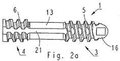
上記スクリュの長尺状の本体1は、適切な生分解性材料で作られている。本体1は、正方形の断面を持つ長手方向の通路2を有する。対応する多角形断面を有し、したがってスクリュを組織へ押し進めるのに用いることができるガイドピンを、通路2へ配設することができる。通路2の断面は、任意の適切な多角形にすることができる。ガイドピンは図示していないことを記しておく。 The
スクリュの遠位部11は第1のねじ部3を有し、同様に、スクリュの近位部は第2のねじ部4を有している。スクリュは、まず遠位部11で組織の中へ押し込まれる。ねじ部3、4のピッチは等しいが、ねじ山5および6のプロフィルは互いに反対である。第1のねじ部3において、ねじ山5の先導面7と、スクリュの中心軸Cに対して直角を成す平面との間の角度α1は、ねじ山5の裏面8と、スクリュの中心軸Cに対して直角を成す平面との間の角度β1よりも大きい。第2のねじ部4において、ねじ部5の先導面7の角度α2は、ねじ山5の裏面8の角度β2よりも小さい。角度α2および角度β1ばかりでなく角度α1および角度β2も実質的に等しくしてあるが、これは必要なことではない。ねじ山3および4の反対のプロフィルがスクリュの把持を向上させる。The
第1のねじ部の芯14の直径は、第2のねじ部の芯15の直径よりもいくぶん小さい。ねじ部の芯14、15の直径を等しくすることもでき、または第1のねじ部の芯14の直径を第2のねじ部の芯15の直径より大きくすることができる。 The diameter of the
図1aないし図1cに示す実施例において、第1および第2のねじ部3、4の両方の芯14、15の直径は、近位部12に最も近いねじ部3、4の区域においては、ねじ部の残部区域におけるよりも大きい。しかし、ねじ部の芯の直径を他のやり方で変えることもでき、またはねじ部全体にわたって一定にすることもできる。 In the embodiment shown in FIGS. 1 a to 1 c, the diameters of the
第1のねじ部のねじ山5の高さを、図1aないし図1cにおけるように、第2のねじ部のねじ山6の高さと同じにすることができるが、ねじ山5、6の高さを互いに異なるようにすることもできる。 The height of the
図1aないし図1cに示す実施例において、第1のねじ部のねじ山のピッチは、第2のねじ部のねじ山6のものと同じである。しかし、これは必ずしも必要なことではなく、第1のねじ部のねじ山5のピッチを第2のねじ部のねじ山6のピッチよりも小さくすることができる。この種の構造は、組織内で損傷の半分どうしを引き合わせるのに役立つ。 In the embodiment shown in FIGS. 1a to 1c, the thread pitch of the first thread is the same as that of the
一方のもしくは両方のねじ部のねじ山5、6をやまばにすることもできる。 The
ねじ切りしていない中間部13が、第1のねじ部3と第2のねじ部4との間に配設されている。非ねじ中間部13は、スクリュを組織内へ押し込むのに役立つ。なぜならば、中間部が、スクリュと組織との間の摩擦面を小さくするからである。さらに、未ねじ切り部13は、スクリュを組織内へ押し込むときに、組織内で損傷の半分どうしを押し合わせることを可能にする。上記の押し合わせはカニューレもしくは他の同様な工具によって行うことができる。 An
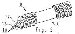
先頭端部9をスクリュの遠位部11へ配設する。先頭端部9は基本形状としては丸い円筒であり、これを斜めに横断して切断して、通路2の遠位部17を同様に斜めに切断する平らな削り面16を遠位部11の端部に形成するようにしている。”斜めに切断する”という概念は、ここでは、切断が中心軸Cに対して斜めに行われることをいう。先頭端部9の基本形状は、円すいとすることもできる。基本形状とは、ここでは、第1のねじ部3の芯14の形状をいう。 A
先頭端部9の端部10は中心軸Cからずれている。スクリュが中心軸Cを周回する場合、先頭端部9が、第1のねじ部3の芯14の直径と実質的に同じ直径を有する円周を周回する。 The
端部10は組織内へ容易に没し、したがって、損傷を広げない。さらに、先頭端部9の構造が、第1のねじ部3のねじ山5を端部10の非常に近くまで延在させることを可能にしており、これが第1のねじ部3の引抜き力を大きくする。図1aないし図1cに示すスクリュにおいて、第1のねじ部のねじ山5の高さは、先頭端部9において低くなっているが、これは必ずしも必要なことではなく、ねじ山5の高さを端部10まで同一にすることができる。 The
スクリュにはスクリュヘッドがまったくないが、第2のねじ部4が近位部12の区域の終端部まで延在するように配設されている。このようにして、スクリュを組織内へ深く押し込んで、半月板へ固定したスクリュが、たとえば関節突起表面をこすりつけないようにすることができる。 The screw has no screw head, but is arranged such that the second threaded
スクリュの本体1は、人体に吸収される、たとえば、乳酸、L-ラクチド、D-ラクチド、D,L-ラクチド、メソラクチド、グリコール酸、グリコリドを重合もしくは共重合することによって製造した生分解性重合体材料、またはラクチドで共重合した環状エステル、または当業者にそれ自体公知の他の同様の材料で作られ、これは本明細書においては、さらに詳細には説明しない。 The
材料を基材と、1つ以上の共重合体添加物を含有する混合物にすることもできる。基材は、乳酸、L-ラクチド、D-ラクチド、D,L-ラクチド、メソラクチド、グリコール酸、グリコリドもしくは同様のものの重合体もしくは共重合体と、随意の他の重合体もしくはラクチドで共重合可能な環状エステルの共重合体である。基材は、α、βおよびγ- ヒドロキシ酪酸、α、βおよびγ- ヒドロキシ吉草酸、さらにステアリン酸、パルミチン酸、オレイン酸、ラウリン酸などの他のヒドロキシ脂肪酸(C11ないしC25)、および同様のものなどの材料に対して所望の特性を与える他のコモノマを含むこともできる。したがって、上述の基材をポリラクチド、ポリグリコリド、ポリ(L-ラクチド)、ポリ(D-ラクチド)、ポリ(L-ラクチド-コ-D、L-ラクチド)、ポリ(L-ラクチド-コ-メソラクチド)、ポリ(L-ラクチド-コ-グリコリド)、ポリ(L-ラクチド-コ-ε-カプロラクトン)、ポリ(D、L-ラクチド-コ-メソラクチド)、ポリ(D、L-ラクチド-コ-グリコリド)、ポリ(D、L-ラクチド-コ-ε-カプロラクトン)、ポリ(メソラクチド-コ-グリコリド)、ポリ(メソラクチド-コ-ε-カプロラクトン)、または同様なものにすることができる。共重合体基材のモノマユニットを50:50 ないし85:15 の比で、またはこの間のいずれかの適した比で存在させることができる。たとえば、適した共重合基材としては、ポリ(L-ラクチド-コ-D、L-ラクチド)70:30 と、ポリ(L-ラクチド-コ-D、L-ラクチド)80:20 と、ポリ(L-ラクチド-コ-グリコリド)85:15 と、ポリ(L-ラクチド-コ-グリコリド)80:20 が含まれる。記すべきことは、基材としての使用に適した重合体および共重合体は、これら自体公知のものであり、当業者によく知られた製造方法で容易に製造することができるということである。The material can also be a mixture containing a substrate and one or more copolymer additives. The substrate can be copolymerized with a polymer or copolymer of lactic acid, L-lactide, D-lactide, D, L-lactide, meso-lactide, glycolic acid, glycolide or the like, and optionally other polymers or lactides A cyclic ester copolymer. The substrates are α, β and γ-hydroxybutyric acid, α, β and γ-hydroxyvaleric acid, as well as other hydroxy fatty acids (C11 to C25 ) such as stearic acid, palmitic acid, oleic acid, lauric acid, and Other comonomers that provide the desired properties for materials such as the like can also be included. Therefore, the above-mentioned base materials are polylactide, polyglycolide, poly (L-lactide), poly (D-lactide), poly (L-lactide-co-D, L-lactide), poly (L-lactide-co-mesolactide) ), Poly (L-lactide-co-glycolide), poly (L-lactide-co-ε-caprolactone), poly (D, L-lactide-co-mesolactide), poly (D, L-lactide-co-glycolide) ), Poly (D, L-lactide-co-ε-caprolactone), poly (mesolactide-co-glycolide), poly (mesolactide-co-ε-caprolactone), or the like. The copolymer-based monomer units can be present in a ratio of 50:50 to 85:15, or any suitable ratio therebetween. For example, suitable copolymer substrates include poly (L-lactide-co-D, L-lactide) 70:30, poly (L-lactide-co-D, L-lactide) 80:20, poly (L-lactide-co-glycolide) 85:15 and poly (L-lactide-co-glycolide) 80:20. It should be noted that polymers and copolymers suitable for use as substrates are known per se and can be readily produced by methods well known to those skilled in the art. .
共重合体添加物は、乳酸、L-ラクチド、D-ラクチド、D、L-ラクチド、メソラクチド、グリコール酸、グリコリド、または同様なもののうちの1つ以上と、トリメチレン炭酸塩およびジオキサノンのうちの1つ以上を含む。有利な共重合体添加物は、ポリ(L-ラクチド-コ-トリメチレン炭酸塩)、ポリ(D、L-ラクチド-コ-トリメチレン炭酸塩)、ポリ(メソラクチド-コ-トリメチレン炭酸塩)、ポリ(グリコール-コ-トリメチレン炭酸塩)、ポリ(L-ラクチド-コ-ジオキサノン)、ポリ(D、L-ラクチド-コ-ジオキサノン)、ポリ(メソラクチド-コ-ジオキサノン)、ポリ(グリコリド-コ-ジオキサノン)および同様のものを含む。 The copolymer additive may comprise one or more of lactic acid, L-lactide, D-lactide, D, L-lactide, mesolactide, glycolic acid, glycolide, or the like, and one of trimethylene carbonate and dioxanone. Including one or more. Advantageous copolymer additives include poly (L-lactide-co-trimethylene carbonate), poly (D, L-lactide-co-trimethylene carbonate), poly (mesolatide-co-trimethylene carbonate), poly ( Glycol-co-trimethylene carbonate), poly (L-lactide-co-dioxanone), poly (D, L-lactide-co-dioxanone), poly (mesolactide-co-dioxanone), poly (glycolide-co-dioxanone) And the like.
基材としての使用に適した重合体および共重合体は公知のものであり、当業者にはよく知られている製造方法で容易に製造することができることを述べておく。 It should be noted that polymers and copolymers suitable for use as a substrate are known and can be readily produced by methods well known to those skilled in the art.
製造材料を、適した着色剤で染めてスクリュの視認度を向上させることができる。着色剤をたとえば、D&C グリーンNo. 6、化学名 1,4- ビス[(4-メチルフェニル)アミノ]-9、10- アンスラセンジオン (CAS No. 128-80-3)、またはD&C バイオレットNo. 2、化学名 1、4-ヒドロキシ[(4-メチルフェニル)アミノ]-9、10- アンスラセンジオン (CAS No. 81-48-1) にすることができ、これら着色剤は共にFDA(米国食品医薬局)によって容認され、指定されている。D&C グリーンNo. 6は、一般の手術または眼科手術で用いる生分解性縫糸の染色における使用に関してFDA の承認(21CFR74.3206)を取得している。D&C バイオレットNo. 2は、さまざまな縫糸と、ポリ(L-乳酸)材料で作られた生分解性半月板用クランプとにおける使用に関する承認(21CFR74.3602)を得ている。 The manufacturing material can be dyed with a suitable colorant to improve the visibility of the screw. For example, D & C Green No. 6,
完成したインプラントにおける着色剤の量は多くて約0.03% 、望ましくは0.002 ないし0.02% である。 The amount of colorant in the finished implant is at most about 0.03%, preferably 0.002 to 0.02%.
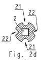
図2aは、本発明のスクリュの概略側面図であり、図2bにおいては同一のスクリュを横から示し、スクリュの中心軸の周りに90度回転させており、図2cは、図1aに示すスクリュの概略斜視図であり、図2dは、図2aに示すスクリュを中間部で切断した概略図である。 FIG. 2a is a schematic side view of the screw of the present invention. In FIG. 2b, the same screw is shown from the side and rotated 90 degrees around the central axis of the screw, and FIG. 2c is the screw shown in FIG. FIG. 2d is a schematic view of the screw shown in FIG. 2a cut at an intermediate portion.
図2aないし図2dに示すスクリュは、スクリュの外面に溝21および22を配設している以外は、上記の図1aないし図1cに示すスクリュと基本的には同じである。 The screw shown in FIGS. 2a to 2d is basically the same as the screw shown in FIGS. 1a to 1c, except that
半月板は、多数の血管のある赤−赤と、赤−赤よりも血管が少ない赤−白と、血管のない白−白の3種類の組織に分けることができる。半月板の損傷を修復するのに用いる公知のインプラントは、赤−赤区域および赤−白区域における損傷の手術にだけ必要である。インプラントの外面へ1つ以上の溝21、22を配設することによってそのインプラントの表面における血管の成長を促進することができることが現在わかった。これによって、赤−赤区域および赤−白区域に加えて、当該インプラントの白−白区域における使用も可能になる。当該インプラントは、したがって、白−白区域における損傷の手術の選択肢を多様化する。 The meniscus can be divided into three types of tissue: red-red with many blood vessels, red-white with fewer blood vessels than red-red, and white-white with no blood vessels. Known implants used to repair meniscal injuries are only needed for surgery of injuries in the red-red and red-white areas. It has now been found that the placement of one or
本体1には溝21、22を配設して、これがねじ部のねじ山5、6の少なくとも一部を切断するようにしている。図2aないし図2dに示す実施例において、溝21、22は第1のねじ部3から中間部13を通って第2のねじ部4へ延在している。図2aないし図2dに示すスクリュにおいて、これらの溝21、22はまっすぐに軸方向に配設しているが、これらを本体1の周囲に螺旋状に配設することもできる。溝21、22のそれぞれがスクリュの一方の端部から他方の端部へ延びて、第1および第2のねじ部のねじ山5、6と、中間部13とを切断している。溝21、22を、より短くして、たとえばこれがねじ部2、3のいずれかのねじ山だけを、さらに、ことによれば中間部13だけを切断するようにすることもできる。
溝21、22 の深さを望ましくは、これが中間部13の表面も切断するようにしているが、これを、それよりも低くなるようにすることもできる。 The depth of the
第1の溝21は断面がU字型であるのに対して、第2の溝22はV字型である。当然、溝21、22の断面および溝の数を、図2aないし図2dに示す実施例とは異なるようにすることができる。 The
図3は、本発明の第3のスクリュの概略斜視図である。スクリュの構造は、先頭端部9を除いては、図1aないし図1cに示すスクリュのものと基本的には同じである。ここでは、先頭端部9は回転対称部品であり、これを斜めに横断して切断して、2つの平らな削り面16aおよび16bを作っている。切断面16a、16bを互いに対して鋭角に配設して、両者がスクリュに刃様端部10を作るようにしている。通路の遠位端部17が刃10を2つの部分に分割している。 FIG. 3 is a schematic perspective view of a third screw of the present invention. The structure of the screw is basically the same as that of the screw shown in FIGS. 1a to 1c except for the
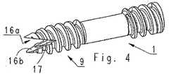
図4は、本発明の第4のスクリュの概略斜視図である。スクリュの構造は、先頭端部9を除いては、図1aないし図1cに示すスクリュのものと基本的には同じである。ここでは、先頭端部9は2つの端部10a、10bを有し、これらをスクリュの中心軸に対して対称に配設して、先頭端部の基本形状にV字型切込み部を切り出している。このようにして、先頭端部9は、スクリュの軸方向に対して斜めになっている2つの平らな削り面16a、16bを有している。削り面16a、16bは、中心軸を通る平面で合流している。端部の数は2つよりも多くすることができることを述べておく。この種の先頭端部にたとえば4つの端部を持たせて、これらをスクリュの中心軸に対して対称に配設することができ、先頭端部の基本形状は、互いに直角に切断する2つのV字型切込み部を有している。 FIG. 4 is a schematic perspective view of a fourth screw of the present invention. The structure of the screw is basically the same as that of the screw shown in FIGS. 1a to 1c except for the
図5は、本発明の第5のスクリュの概略斜視図である。ここでも、スクリュの構造は、先頭端部9を除いては、図1aないし図1cに示すスクリュのものと基本的には同じである。ここでは、平らな削り面16を円筒状に凹面にして、端部10がとくに鋭くなるようにしている。 FIG. 5 is a schematic perspective view of a fifth screw of the present invention. Again, the structure of the screw is basically the same as that of the screw shown in FIGS. 1a to 1c except for the
図6は、本発明の第6のスクリュの概略斜視図である。ここでも、スクリュの構造は、先頭端部9を除いては、図1aないし図1cに示すスクリュのものと基本的には同じである。ここでは、平らな削り面16を円筒状に凸面にして、端部10が、図1aないし図1cに示すスクリュにおけるよりも鋭くならないようにしている。 FIG. 6 is a schematic perspective view of a sixth screw of the present invention. Again, the structure of the screw is basically the same as that of the screw shown in FIGS. 1a to 1c except for the
先頭端部9を鋭利な形に設計して、インプラントの組織への貫通を容易にしている。同時に、本発明のインプラントの先頭端部9を、そのねじ山の表面積を大きくするように形作り、これによってインプラントの引抜き力を増すようにしている。一方では組織の特性と、他方では組織の損傷をふさぐのに必要な引抜き力とが、それぞれの場合に先頭端部9のどの形が最適であるかを決める。 The
用語「平らな面」とは、ここでは互いに平行に配設された実質的に直状の表面要素から作られた面をいう。 The term “flat surface” here refers to a surface made of substantially straight surface elements arranged parallel to each other.
技術の進歩につれて、本発明の概念をさまざまな方式で実行できることは当業者には明らかであろう。本発明およびその実施例は上述の例に限定されることはなく、特許請求の範囲内で変えることができる。 It will be apparent to those skilled in the art that as technology advances, the concepts of the present invention can be implemented in various ways. The invention and its embodiments are not limited to the examples described above but may vary within the scope of the claims.
Claims (20)
Translated fromJapanese該本体へその軸方向に配設した通路と、
該本体の遠位部へ配設した第1のねじ部と、
該本体の近位部へ配設した第2のねじ部と、
前記遠位部へ配設され、斜めに横断して切断されて端部に平らな削り面が形成された回転対称部品の基本形状の先頭端部と、
前記第1のねじ部と第2のねじ部との間に配設した実質的に非ねじ中間部とを含むことを特徴とする軟組織用スクリュ。An elongate body made of a biodegradable material and having a proximal portion and a distal portion;
A passage disposed in the axial direction of the main body;
A first thread disposed on the distal portion of the body;
A second thread disposed on the proximal portion of the body;
A leading end portion of a basic shape of a rotationally symmetric part disposed on the distal portion and cut obliquely across the end portion to form a flat cutting surface at the end portion;
A screw for soft tissue, comprising a substantially non-thread intermediate portion disposed between the first screw portion and the second screw portion.
生分解性重合体もしくは共重合体を含む基材と、
共重合体添加物を含まない該基材から作られるインプラントの常温における引張強さよりも低いインプラントの常温における引張強さを与える1つ以上のモノマを含む共重合体添加物とを含むことを特徴とする軟組織用スクリュ。The screw for soft tissue according to claim 1, wherein the screw is formed from a melt-mixed polymer composition, and the melt-mixed polymer composition comprises:
A substrate comprising a biodegradable polymer or copolymer;
And a copolymer additive comprising one or more monomers that provide a tensile strength at room temperature of the implant that is lower than the tensile strength at room temperature of the implant made from the substrate without the copolymer additive. A soft tissue screw.
Applications Claiming Priority (2)
| Application Number | Priority Date | Filing Date | Title |
|---|---|---|---|
| US10/438,187US20040230195A1 (en) | 2003-05-14 | 2003-05-14 | Soft-tissue screw |
| PCT/FI2004/000286WO2004100802A1 (en) | 2003-05-14 | 2004-05-12 | Soft-tissue screw |
Publications (2)
| Publication Number | Publication Date |
|---|---|
| JP2006528895Atrue JP2006528895A (en) | 2006-12-28 |
| JP2006528895A5 JP2006528895A5 (en) | 2007-04-05 |
Family
ID=33417523
Family Applications (1)
| Application Number | Title | Priority Date | Filing Date |
|---|---|---|---|
| JP2006530304APendingJP2006528895A (en) | 2003-05-14 | 2004-05-12 | Soft tissue screw |
Country Status (5)
| Country | Link |
|---|---|
| US (1) | US20040230195A1 (en) |
| EP (1) | EP1622519A1 (en) |
| JP (1) | JP2006528895A (en) |
| KR (1) | KR20060012291A (en) |
| WO (1) | WO2004100802A1 (en) |
Cited By (4)
| Publication number | Priority date | Publication date | Assignee | Title |
|---|---|---|---|---|
| JP2006305348A (en)* | 2003-06-13 | 2006-11-09 | Tyco Healthcare Group Lp | Surgical fastener with predetermined resorption rate |
| JP2010517673A (en)* | 2007-02-07 | 2010-05-27 | エイペックス バイオメディカル カンパニー, エルエルシー | Rotational asymmetric bone screw |
| JP2016503666A (en)* | 2012-12-11 | 2016-02-08 | ヒューワイス アイピー ホールディング,エルエルシー | Condensation implant |
| JP2021510554A (en)* | 2018-01-10 | 2021-04-30 | シー・アール・バード・インコーポレーテッドC R Bard Incorporated | Surgical fasteners for joint-moving surgical instruments |
Families Citing this family (33)
| Publication number | Priority date | Publication date | Assignee | Title |
|---|---|---|---|---|
| US7641657B2 (en) | 2003-06-10 | 2010-01-05 | Trans1, Inc. | Method and apparatus for providing posterior or anterior trans-sacral access to spinal vertebrae |
| US7014633B2 (en) | 2000-02-16 | 2006-03-21 | Trans1, Inc. | Methods of performing procedures in the spine |
| US7744599B2 (en) | 2000-02-16 | 2010-06-29 | Trans1 Inc. | Articulating spinal implant |
| US6740090B1 (en) | 2000-02-16 | 2004-05-25 | Trans1 Inc. | Methods and apparatus for forming shaped axial bores through spinal vertebrae |
| DK1578315T3 (en) | 2000-02-16 | 2008-10-06 | Trans1 Inc | Device for vertebral column distribution and fusion |
| US6558390B2 (en) | 2000-02-16 | 2003-05-06 | Axiamed, Inc. | Methods and apparatus for performing therapeutic procedures in the spine |
| AU2004283727A1 (en) | 2003-10-23 | 2005-05-06 | Trans1 Inc. | Tools and tool kits for performing minimally invasive procedures on the spine |
| CA2562061C (en)* | 2004-04-26 | 2011-06-21 | Bioduct Llc | Stent for avascular meniscal repair and regeneration |
| US20060106389A1 (en)* | 2004-11-12 | 2006-05-18 | Reber Erik W | Anti-migration threaded fastener |
| US8740955B2 (en) | 2005-02-15 | 2014-06-03 | Zimmer, Inc. | Bone screw with multiple thread profiles for far cortical locking and flexible engagement to a bone |
| US8197523B2 (en) | 2005-02-15 | 2012-06-12 | Apex Biomedical Company, Llc | Bone screw for positive locking but flexible engagement to a bone |
| WO2006133256A2 (en)* | 2005-06-07 | 2006-12-14 | Flex Partners, Inc. | Method for restoration of nutrient flow to nucleus pulposa |
| US20070055257A1 (en)* | 2005-06-30 | 2007-03-08 | Alex Vaccaro | Cannulated screw access system |
| WO2011092681A1 (en)* | 2010-01-26 | 2011-08-04 | Sialo-Lite Ltd. | Dental implants, devices and methods associated with dental implantation procedures |
| ATE523155T1 (en)* | 2005-10-28 | 2011-09-15 | Medartis Ag | THREAD FORMING SCREW |
| US7731738B2 (en)* | 2005-12-09 | 2010-06-08 | Orthopro, Llc | Cannulated screw |
| US8403943B2 (en)* | 2006-08-07 | 2013-03-26 | Howmedica Osteonics Corp. | Insertion system for implanting a medical device and surgical methods |
| US20080033487A1 (en)* | 2006-08-07 | 2008-02-07 | Bioduct, Llc | Medical device for repair of tissue and method for implantation and fixation |
| US20080177333A1 (en)* | 2006-10-24 | 2008-07-24 | Warsaw Orthopedic, Inc. | Adjustable jacking implant |
| RU2712028C2 (en)* | 2009-11-09 | 2020-01-24 | Спайнуэлдинг Аг | Medical device for implantation into human or animal body or for strengthening of human or animal solid tissue for further implantation of separate implant and dental implant |
| ES2456317T3 (en)* | 2010-02-26 | 2014-04-22 | Biedermann Technologies Gmbh & Co. Kg | Bone screw |
| CA2827235A1 (en)* | 2011-02-14 | 2012-08-23 | The Royal Institution For The Advancement Of Learning / Mcgill Universit Y | Systems and methods for injecting fluid into bone and for inserting bone screws, and bone screws for same |
| US10039621B2 (en) | 2011-03-23 | 2018-08-07 | Huwais IP Holding LLC | Autografting osteotome |
| US9028253B2 (en) | 2011-03-23 | 2015-05-12 | Huwais IP Holding LLC | Fluted osteotome and surgical method for use |
| US9089438B2 (en) | 2011-06-28 | 2015-07-28 | Spinal Elements, Inc. | Apparatus for promoting movement of nutrients to intervertebral space and method of use |
| US9072559B2 (en) | 2013-03-08 | 2015-07-07 | DePuy Synthes Products, Inc. | Universal length screw design and cutting instrument |
| WO2014159225A2 (en) | 2013-03-14 | 2014-10-02 | Baxano Surgical, Inc. | Spinal implants and implantation system |
| AU2017207510B9 (en) | 2016-01-14 | 2021-03-25 | Huwais IP Holding LLC | Autografting tool with enhanced flute profile and methods of use |
| ES2857583T3 (en) | 2016-02-07 | 2021-09-29 | Huwais IP Holding LLC | Anchor bolt with condensation attributes |
| CN108186103B (en)* | 2018-02-28 | 2021-03-09 | 中国人民解放军陆军军医大学第一附属医院 | Joint fusion fixing nail |
| CA3115839A1 (en) | 2018-11-06 | 2020-05-14 | Huwais IP Holding LLC | Autografting tool for deep reach applications |
| CN113827333A (en)* | 2021-10-13 | 2021-12-24 | 上海市第六人民医院 | Novel medical hollow nail |
| US20230285156A1 (en)* | 2022-03-11 | 2023-09-14 | University Of Maryland, Baltimore | Device and method for sacroiliac fusion |
Citations (4)
| Publication number | Priority date | Publication date | Assignee | Title |
|---|---|---|---|---|
| JPS53128181A (en)* | 1977-02-24 | 1978-11-08 | Herbert Timothy James | Screw for bonding bones |
| JPH04292173A (en)* | 1990-12-13 | 1992-10-16 | Cook Inc | Bone injection needle |
| US5730744A (en)* | 1994-09-27 | 1998-03-24 | Justin; Daniel F. | Soft tissue screw, delivery device, and method |
| WO2002056778A1 (en)* | 2001-01-17 | 2002-07-25 | Synthes (U.S.A.) | Bone screw |
Family Cites Families (52)
| Publication number | Priority date | Publication date | Assignee | Title |
|---|---|---|---|---|
| US3309274A (en)* | 1962-07-23 | 1967-03-14 | Brilliant Herbert | Use of fluorescent dyes in dental diagnostic methods |
| US3739773A (en)* | 1963-10-31 | 1973-06-19 | American Cyanamid Co | Polyglycolic acid prosthetic devices |
| NO125290B (en)* | 1968-10-23 | 1972-08-14 | Bultfabriks Ab | |
| FR2342714A1 (en)* | 1976-03-03 | 1977-09-30 | Tieche Jacques | ANCHOR SCREWS FOR DENTAL FILLINGS |
| FR2460657A1 (en)* | 1979-07-12 | 1981-01-30 | Anvar | BIODEGRADABLE IMPLANT FOR USE AS A BONE PROSTHESIS PIECE |
| US4776329A (en)* | 1985-09-20 | 1988-10-11 | Richards Medical Company | Resorbable compressing screw and method |
| US4973333A (en)* | 1985-09-20 | 1990-11-27 | Richards Medical Company | Resorbable compressing screw and method |
| CH671150A5 (en)* | 1986-10-13 | 1989-08-15 | Jaquet Orthopedie | |
| FI81498C (en)* | 1987-01-13 | 1990-11-12 | Biocon Oy | SURGICAL MATERIAL OCH INSTRUMENT. |
| US4905679A (en)* | 1988-02-22 | 1990-03-06 | M P Operation, Inc. | Bone fracture reduction device and method of internal fixation of bone fractures |
| DE3831657A1 (en)* | 1988-09-17 | 1990-03-22 | Boehringer Ingelheim Kg | DEVICE FOR THE OSTEOSYNTHESIS AND METHOD FOR THE PRODUCTION THEREOF |
| US5601559A (en)* | 1988-10-24 | 1997-02-11 | Cook Incorporated | Intraosseous needle |
| US4950270A (en)* | 1989-02-03 | 1990-08-21 | Boehringer Mannheim Corporation | Cannulated self-tapping bone screw |
| US5019079A (en)* | 1989-11-20 | 1991-05-28 | Zimmer, Inc. | Bone screw |
| US5129901A (en)* | 1991-06-10 | 1992-07-14 | Decoste Vern X | Cannulated orthopedic screw |
| US5275601A (en)* | 1991-09-03 | 1994-01-04 | Synthes (U.S.A) | Self-locking resorbable screws and plates for internal fixation of bone fractures and tendon-to-bone attachment |
| US5242447A (en)* | 1992-02-06 | 1993-09-07 | Howmedica Inc. | Pin with tapered root diameter |
| AU672596B2 (en)* | 1992-02-14 | 1996-10-10 | Smith & Nephew, Inc. | Polymeric screws and coatings for surgical uses |
| US6030162A (en)* | 1998-12-18 | 2000-02-29 | Acumed, Inc. | Axial tension screw |
| US5405359A (en)* | 1994-04-29 | 1995-04-11 | Pierce; Javi | Toggle wedge |
| US5569250A (en)* | 1994-03-01 | 1996-10-29 | Sarver; David R. | Method and apparatus for securing adjacent bone portions |
| AU689846B2 (en)* | 1994-03-29 | 1998-04-09 | Zimmer Gmbh | Screw made of biodegradable material for bone surgery purposes, and screwdriver suitable therefor |
| US6001101A (en)* | 1994-07-05 | 1999-12-14 | Depuy France | Screw device with threaded head for permitting the coaptation of two bone fragments |
| US5569252A (en)* | 1994-09-27 | 1996-10-29 | Justin; Daniel F. | Device for repairing a meniscal tear in a knee and method |
| US5601553A (en)* | 1994-10-03 | 1997-02-11 | Synthes (U.S.A.) | Locking plate and bone screw |
| US5536127A (en)* | 1994-10-13 | 1996-07-16 | Pennig; Dietmar | Headed screw construction for use in fixing the position of an intramedullary nail |
| US5605458A (en)* | 1995-03-06 | 1997-02-25 | Crystal Medical Technology, A Division Of Folsom Metal Products, Inc. | Negative load flank implant connector |
| US5601429A (en)* | 1995-08-11 | 1997-02-11 | Blacklock; Gordon D. | Dental implant anchor |
| DE29520312U1 (en)* | 1995-12-21 | 1996-02-08 | Leibinger Medizintech | Bone screw |
| SE9600208D0 (en)* | 1996-01-19 | 1996-01-19 | Astra Ab | Fixture and prosthesis including the same |
| SE9600517D0 (en)* | 1996-02-13 | 1996-02-13 | Astra Ab | Screw thread implant |
| US5919193A (en)* | 1996-03-14 | 1999-07-06 | Slavitt; Jerome A. | Method and kit for surgically correcting malformations in digits of a finger or toe |
| US5868749A (en)* | 1996-04-05 | 1999-02-09 | Reed; Thomas M. | Fixation devices |
| FR2750595B1 (en)* | 1996-07-02 | 1998-12-04 | Dev Sed Soc Et | MEDICAL SCREWS ESPECIALLY FOR SURGERY AND ANCILLARY OF POSITION |
| US5733307A (en)* | 1996-09-17 | 1998-03-31 | Amei Technologies, Inc. | Bone anchor having a suture trough |
| US6692499B2 (en)* | 1997-07-02 | 2004-02-17 | Linvatec Biomaterials Oy | Surgical fastener for tissue treatment |
| US5984681A (en)* | 1997-09-02 | 1999-11-16 | Huang; Barney K. | Dental implant and method of implanting |
| WO1999011177A2 (en)* | 1997-09-05 | 1999-03-11 | Deslauriers Richard J | Self-retaining anchor track and method of making and using same |
| US6264677B1 (en)* | 1997-10-15 | 2001-07-24 | Applied Biological Concepts, Inc. | Wedge screw suture anchor |
| US6269716B1 (en)* | 1998-11-18 | 2001-08-07 | Macropore, Inc. | High-torque resorbable screws |
| US6086371A (en)* | 1998-02-05 | 2000-07-11 | Sulzer Orthopedics Inc. | Dental implant delivery system having driver mount with removable flange |
| US6387113B1 (en)* | 1999-02-02 | 2002-05-14 | Biomet, Inc. | Method and apparatus for repairing a torn meniscus |
| FR2792521B1 (en)* | 1999-04-22 | 2001-08-31 | New Deal | COMPRESSION OSTEOSYNTHESIS SCREWS AND IMPLEMENTATION ANCILLARY |
| US6123711A (en)* | 1999-06-10 | 2000-09-26 | Winters; Thomas F. | Tissue fixation device and method |
| DE59906133D1 (en)* | 1999-08-14 | 2003-07-31 | Aesculap Ag & Co Kg | BONE SCREW |
| DE60026136T2 (en)* | 1999-11-15 | 2006-11-23 | Arthrex Inc., Naples | Rejuvenating bioabsorbing interference screw for the osteal attachment of ligaments |
| US6468277B1 (en)* | 2000-04-04 | 2002-10-22 | Ethicon, Inc. | Orthopedic screw and method |
| US6569186B1 (en)* | 2000-10-05 | 2003-05-27 | Biomet, Inc. | Soft tissue screw and fixation device |
| US6565573B1 (en)* | 2001-04-16 | 2003-05-20 | Smith & Nephew, Inc. | Orthopedic screw and method of use |
| US7122037B2 (en)* | 2001-05-17 | 2006-10-17 | Inion Ltd. | Bone fracture fastener and material for production thereof |
| US6866666B1 (en)* | 2001-06-28 | 2005-03-15 | Medicinelodge, Inc. | System and method for attaching soft tissue to bone |
| US8409250B2 (en)* | 2002-01-23 | 2013-04-02 | Arthrex, Inc. | Meniscal repair system and method |
- 2003
- 2003-05-14USUS10/438,187patent/US20040230195A1/ennot_activeAbandoned
- 2004
- 2004-05-12EPEP04732335Apatent/EP1622519A1/ennot_activeWithdrawn
- 2004-05-12WOPCT/FI2004/000286patent/WO2004100802A1/enactiveApplication Filing
- 2004-05-12JPJP2006530304Apatent/JP2006528895A/enactivePending
- 2004-05-12KRKR1020057021689Apatent/KR20060012291A/ennot_activeAbandoned
Patent Citations (4)
| Publication number | Priority date | Publication date | Assignee | Title |
|---|---|---|---|---|
| JPS53128181A (en)* | 1977-02-24 | 1978-11-08 | Herbert Timothy James | Screw for bonding bones |
| JPH04292173A (en)* | 1990-12-13 | 1992-10-16 | Cook Inc | Bone injection needle |
| US5730744A (en)* | 1994-09-27 | 1998-03-24 | Justin; Daniel F. | Soft tissue screw, delivery device, and method |
| WO2002056778A1 (en)* | 2001-01-17 | 2002-07-25 | Synthes (U.S.A.) | Bone screw |
Cited By (8)
| Publication number | Priority date | Publication date | Assignee | Title |
|---|---|---|---|---|
| JP2006305348A (en)* | 2003-06-13 | 2006-11-09 | Tyco Healthcare Group Lp | Surgical fastener with predetermined resorption rate |
| JP2010517673A (en)* | 2007-02-07 | 2010-05-27 | エイペックス バイオメディカル カンパニー, エルエルシー | Rotational asymmetric bone screw |
| JP2016503666A (en)* | 2012-12-11 | 2016-02-08 | ヒューワイス アイピー ホールディング,エルエルシー | Condensation implant |
| JP2021510554A (en)* | 2018-01-10 | 2021-04-30 | シー・アール・バード・インコーポレーテッドC R Bard Incorporated | Surgical fasteners for joint-moving surgical instruments |
| US11957343B2 (en) | 2018-01-10 | 2024-04-16 | C.R. Bard, Inc. | Surgical fasteners for articulating surgical instruments |
| JP7488764B2 (en) | 2018-01-10 | 2024-05-22 | シー・アール・バード・インコーポレーテッド | Surgical fastener for an articulating surgical instrument |
| JP2024126025A (en)* | 2018-01-10 | 2024-09-19 | シー・アール・バード・インコーポレーテッド | Surgical fastener for an articulating surgical instrument |
| US12245765B2 (en) | 2018-01-10 | 2025-03-11 | C.R. Bard, Inc. | Surgical fasteners for articulating surgical instruments |
Also Published As
| Publication number | Publication date |
|---|---|
| KR20060012291A (en) | 2006-02-07 |
| US20040230195A1 (en) | 2004-11-18 |
| WO2004100802A1 (en) | 2004-11-25 |
| EP1622519A1 (en) | 2006-02-08 |
Similar Documents
| Publication | Publication Date | Title |
|---|---|---|
| JP2006528895A (en) | Soft tissue screw | |
| EP0625887B1 (en) | Polymeric screws and coatings for surgical uses | |
| JP4864276B2 (en) | Medical screw and its mounting method | |
| EP1864616B2 (en) | Method for producing a bone fixation device | |
| EP1131007B1 (en) | Bioabsorbable surgical screw and washer system | |
| US5571139A (en) | Bidirectional suture anchor | |
| JP5562829B2 (en) | Surgical procedure self-holding system | |
| US20120029577A1 (en) | System and method for bone fixation using biodegradable screw having radial cutouts | |
| EP2651322A2 (en) | Peek-rich bone screw | |
| EP2427125A1 (en) | Thread having coated anchoring structures for anchoring in biological tissues and process for production thereof | |
| CN211583317U (en) | Orthopedic anchors for fixation of soft tissue and their fittings | |
| AU2015360319A1 (en) | Suture anchors having ribbed enhancements | |
| CN113679441B (en) | Extrusion nail with anti-skid function | |
| CN213722192U (en) | Extrusion nail with occlusion function and assembly tool of extrusion nail | |
| AU2249599A (en) | Wedge shaped suture anchor and method of implantation |
Legal Events
| Date | Code | Title | Description |
|---|---|---|---|
| A521 | Request for written amendment filed | Free format text:JAPANESE INTERMEDIATE CODE: A523 Effective date:20070216 | |
| A621 | Written request for application examination | Free format text:JAPANESE INTERMEDIATE CODE: A621 Effective date:20070216 | |
| A977 | Report on retrieval | Free format text:JAPANESE INTERMEDIATE CODE: A971007 Effective date:20091028 | |
| A131 | Notification of reasons for refusal | Free format text:JAPANESE INTERMEDIATE CODE: A131 Effective date:20091110 | |
| A02 | Decision of refusal | Free format text:JAPANESE INTERMEDIATE CODE: A02 Effective date:20100406 |