JP2006526780A - Tray assembly for optical inspection equipment - Google Patents
Tray assembly for optical inspection equipmentDownload PDFInfo
- Publication number
- JP2006526780A JP2006526780AJP2006514336AJP2006514336AJP2006526780AJP 2006526780 AJP2006526780 AJP 2006526780AJP 2006514336 AJP2006514336 AJP 2006514336AJP 2006514336 AJP2006514336 AJP 2006514336AJP 2006526780 AJP2006526780 AJP 2006526780A
- Authority
- JP
- Japan
- Prior art keywords
- insert
- assembly
- support tray
- chamber
- tray
- Prior art date
- Legal status (The legal status is an assumption and is not a legal conclusion. Google has not performed a legal analysis and makes no representation as to the accuracy of the status listed.)
- Granted
Links
- 238000007689inspectionMethods0.000titleclaimsabstractdescription58
- 230000003287optical effectEffects0.000titledescription13
- 239000007788liquidSubstances0.000claimsabstractdescription89
- 239000003153chemical reaction reagentSubstances0.000claimsdescription164
- 238000012360testing methodMethods0.000claimsdescription28
- 238000001514detection methodMethods0.000claimsdescription4
- 210000001124body fluidAnatomy0.000description18
- 239000010839body fluidSubstances0.000description16
- 210000002700urineAnatomy0.000description16
- 238000000034methodMethods0.000description8
- 239000000969carrierSubstances0.000description6
- 230000000712assemblyEffects0.000description4
- 238000000429assemblyMethods0.000description4
- 210000004369bloodAnatomy0.000description3
- 239000008280bloodSubstances0.000description3
- 230000008859changeEffects0.000description3
- 210000000265leukocyteAnatomy0.000description3
- 230000003595spectral effectEffects0.000description3
- 230000002949hemolytic effectEffects0.000description2
- 230000006872improvementEffects0.000description2
- 238000003780insertionMethods0.000description2
- 230000037431insertionEffects0.000description2
- 239000003550markerSubstances0.000description2
- 230000002485urinary effectEffects0.000description2
- 238000005353urine analysisMethods0.000description2
- 238000010521absorption reactionMethods0.000description1
- 230000002411adverseEffects0.000description1
- 238000004458analytical methodMethods0.000description1
- 239000003795chemical substances by applicationSubstances0.000description1
- 238000011109contaminationMethods0.000description1
- 238000002405diagnostic procedureMethods0.000description1
- 230000003670easy-to-cleanEffects0.000description1
- 210000003743erythrocyteAnatomy0.000description1
- 238000007373indentationMethods0.000description1
- 230000000977initiatory effectEffects0.000description1
- 239000000463materialSubstances0.000description1
- 230000013011matingEffects0.000description1
- 238000005259measurementMethods0.000description1
- 230000007246mechanismEffects0.000description1
- 238000012986modificationMethods0.000description1
- 230000004048modificationEffects0.000description1
- 238000009597pregnancy testMethods0.000description1
- 230000008569processEffects0.000description1
- 238000012545processingMethods0.000description1
- 239000000758substrateSubstances0.000description1
- 230000000007visual effectEffects0.000description1
Images


Classifications
- G—PHYSICS
- G01—MEASURING; TESTING
- G01N—INVESTIGATING OR ANALYSING MATERIALS BY DETERMINING THEIR CHEMICAL OR PHYSICAL PROPERTIES
- G01N21/00—Investigating or analysing materials by the use of optical means, i.e. using sub-millimetre waves, infrared, visible or ultraviolet light
- G01N21/84—Systems specially adapted for particular applications
- G01N21/8483—Investigating reagent band
- B—PERFORMING OPERATIONS; TRANSPORTING
- B01—PHYSICAL OR CHEMICAL PROCESSES OR APPARATUS IN GENERAL
- B01L—CHEMICAL OR PHYSICAL LABORATORY APPARATUS FOR GENERAL USE
- B01L9/00—Supporting devices; Holding devices
- B01L9/52—Supports specially adapted for flat sample carriers, e.g. for plates, slides, chips
- G—PHYSICS
- G01—MEASURING; TESTING
- G01N—INVESTIGATING OR ANALYSING MATERIALS BY DETERMINING THEIR CHEMICAL OR PHYSICAL PROPERTIES
- G01N21/00—Investigating or analysing materials by the use of optical means, i.e. using sub-millimetre waves, infrared, visible or ultraviolet light
- G01N21/17—Systems in which incident light is modified in accordance with the properties of the material investigated
- G01N21/25—Colour; Spectral properties, i.e. comparison of effect of material on the light at two or more different wavelengths or wavelength bands
- G01N21/27—Colour; Spectral properties, i.e. comparison of effect of material on the light at two or more different wavelengths or wavelength bands using photo-electric detection ; circuits for computing concentration
- G01N21/274—Calibration, base line adjustment, drift correction
- G—PHYSICS
- G01—MEASURING; TESTING
- G01N—INVESTIGATING OR ANALYSING MATERIALS BY DETERMINING THEIR CHEMICAL OR PHYSICAL PROPERTIES
- G01N21/00—Investigating or analysing materials by the use of optical means, i.e. using sub-millimetre waves, infrared, visible or ultraviolet light
- G01N21/17—Systems in which incident light is modified in accordance with the properties of the material investigated
- G01N21/47—Scattering, i.e. diffuse reflection
- G01N21/4738—Diffuse reflection, e.g. also for testing fluids, fibrous materials
- G—PHYSICS
- G01—MEASURING; TESTING
- G01N—INVESTIGATING OR ANALYSING MATERIALS BY DETERMINING THEIR CHEMICAL OR PHYSICAL PROPERTIES
- G01N21/00—Investigating or analysing materials by the use of optical means, i.e. using sub-millimetre waves, infrared, visible or ultraviolet light
- G01N21/75—Systems in which material is subjected to a chemical reaction, the progress or the result of the reaction being investigated
- G01N21/77—Systems in which material is subjected to a chemical reaction, the progress or the result of the reaction being investigated by observing the effect on a chemical indicator
- G01N21/78—Systems in which material is subjected to a chemical reaction, the progress or the result of the reaction being investigated by observing the effect on a chemical indicator producing a change of colour
- B—PERFORMING OPERATIONS; TRANSPORTING
- B01—PHYSICAL OR CHEMICAL PROCESSES OR APPARATUS IN GENERAL
- B01L—CHEMICAL OR PHYSICAL LABORATORY APPARATUS FOR GENERAL USE
- B01L2300/00—Additional constructional details
- B01L2300/08—Geometry, shape and general structure
- B01L2300/0809—Geometry, shape and general structure rectangular shaped
- B01L2300/0825—Test strips
- G—PHYSICS
- G01—MEASURING; TESTING
- G01J—MEASUREMENT OF INTENSITY, VELOCITY, SPECTRAL CONTENT, POLARISATION, PHASE OR PULSE CHARACTERISTICS OF INFRARED, VISIBLE OR ULTRAVIOLET LIGHT; COLORIMETRY; RADIATION PYROMETRY
- G01J3/00—Spectrometry; Spectrophotometry; Monochromators; Measuring colours
- G01J3/28—Investigating the spectrum
- G01J2003/2866—Markers; Calibrating of scan
- G—PHYSICS
- G01—MEASURING; TESTING
- G01N—INVESTIGATING OR ANALYSING MATERIALS BY DETERMINING THEIR CHEMICAL OR PHYSICAL PROPERTIES
- G01N21/00—Investigating or analysing materials by the use of optical means, i.e. using sub-millimetre waves, infrared, visible or ultraviolet light
- G01N21/01—Arrangements or apparatus for facilitating the optical investigation
- G01N21/03—Cuvette constructions
- G01N2021/0325—Cells for testing reactions, e.g. containing reagents
- G—PHYSICS
- G01—MEASURING; TESTING
- G01N—INVESTIGATING OR ANALYSING MATERIALS BY DETERMINING THEIR CHEMICAL OR PHYSICAL PROPERTIES
- G01N2201/00—Features of devices classified in G01N21/00
- G01N2201/02—Mechanical
- G01N2201/024—Modular construction
- G01N2201/0245—Modular construction with insertable-removable part
- G—PHYSICS
- G01—MEASURING; TESTING
- G01N—INVESTIGATING OR ANALYSING MATERIALS BY DETERMINING THEIR CHEMICAL OR PHYSICAL PROPERTIES
- G01N2201/00—Features of devices classified in G01N21/00
- G01N2201/12—Circuits of general importance; Signal processing
- G01N2201/127—Calibration; base line adjustment; drift compensation
- G01N2201/12792—Compensating own radiation in apparatus
Landscapes
- Physics & Mathematics (AREA)
- Health & Medical Sciences (AREA)
- Chemical & Material Sciences (AREA)
- Life Sciences & Earth Sciences (AREA)
- General Physics & Mathematics (AREA)
- Pathology (AREA)
- Analytical Chemistry (AREA)
- Biochemistry (AREA)
- General Health & Medical Sciences (AREA)
- Immunology (AREA)
- Chemical Kinetics & Catalysis (AREA)
- Engineering & Computer Science (AREA)
- Molecular Biology (AREA)
- Plasma & Fusion (AREA)
- Clinical Laboratory Science (AREA)
- Mathematical Physics (AREA)
- Theoretical Computer Science (AREA)
- Spectroscopy & Molecular Physics (AREA)
- Investigating Or Analysing Materials By Optical Means (AREA)
- Automatic Analysis And Handling Materials Therefor (AREA)
- Investigating Or Analysing Biological Materials (AREA)
- Investigating Or Analysing Materials By The Use Of Chemical Reactions (AREA)
Abstract
Translated fromJapaneseDescription
Translated fromJapanese関連出願の相互参照
本出願は、同時係属中の仮出願である、2003年6月3日に出願された米国特許出願第60/475,288号(代理人事件番号BYRK−27PR)から優先権を主張するものであり、その全体を参照により本出願に組込む。
開示の分野CROSS REFERENCE TO RELATED APPLICATIONS This application is prioritized from co-pending provisional application US Patent Application No. 60 / 475,288 filed on June 3, 2003 (attorney case number BYRK-27PR). Which is incorporated herein by reference in its entirety.
Disclosure field
本開示は、光学的に検査する体液サンプルに対して試験を行う装置および方法に関し、より詳細には、この装置と共に使用する液体サンプルキャリヤトレイに関する。さらに詳細には、本開示は、光学検査装置内における試験のために、少なくとも2種類の異なる液体サンプルキャリヤを交互に支持するトレイアセンブリに関する。 The present disclosure relates to an apparatus and method for testing a body fluid sample to be optically examined, and more particularly to a liquid sample carrier tray for use with the apparatus. More particularly, the present disclosure relates to a tray assembly that alternately supports at least two different liquid sample carriers for testing in an optical inspection apparatus.
開示の背景
多様な医療診断目的で、反射分光器(reflectance spectroscope)を使用して体液のサンプルを分析すること、例えばヒトの尿の色を決定することが有用である。従来型の分光器は、白色の非反応パッド上に配置した尿サンプルの色を、パッドを照明し、可視光の異なる波長に対する強度を各々有する多数の反射率の読みをパッドから測定して決定することができる。その後、パッド上の尿の色を、赤、緑、青色および赤外線反射信号の相対強度に基づいて決定する。BACKGROUND OF THE DISCLOSURE For a variety of medical diagnostic purposes, it is useful to analyze a sample of body fluid using a reflectance spectroscope, for example to determine the color of human urine. Conventional spectrometers determine the color of a urine sample placed on a white non-reactive pad by illuminating the pad and measuring multiple reflectance readings, each with intensities for different wavelengths of visible light, from the pad can do. Thereafter, the color of the urine on the pad is determined based on the relative intensities of the red, green, blue and infrared reflected signals.
従来の分光器は、多数の異なる試薬パッドを上設した試薬片を用いて、多数の異なる尿分析試験を行うために使用できる。各々の試薬パッドには、ある一定の種類の尿中の構成要素、例えば白血球(leukocytes)(白血球(white blood cells))または赤血球の存在に対して色変化を生じる異なる試薬を具備することができる。 Conventional spectrometers can be used to perform a number of different urine analysis tests using reagent strips with a number of different reagent pads. Each reagent pad may contain different reagents that cause a color change in the presence of certain types of urinary components, such as leukocytes (white blood cells) or red blood cells. .
従来の分光器では、試薬片を尿サンプル中に浸漬し、試薬片から余剰の尿を拭い、試薬片を分光光度計の指定された場所に配置し、開始ボタンを押して、分光器に試薬片の自動処理および検査を開始させることで試薬片の検査工程を実施することができる。 In a conventional spectrometer, the reagent piece is immersed in the urine sample, the excess urine is wiped from the reagent piece, the reagent piece is placed at the designated location on the spectrophotometer, the start button is pressed, and the reagent piece is placed in the spectrometer. By initiating the automatic processing and inspection, the reagent piece inspection process can be carried out.
例えば、本開示の譲受人に譲渡された米国特許第5,654,803号は、尿中の潜血の非溶血レベルを測定する装置および方法を開示している。この装置は、尿サンプルを配置した試薬パッドの複数の異なる部分を連続的に照明するための白熱電球と、試薬パッドから受光した光を検出し、試薬パッドの異なる部分の対応する1つから受光した光に対応して複数の反射信号を生成するための検出器アレイとを具備する。この装置はさらに、反射信号の1つの強度が反射信号の別の1つの強度と実質的に異なるか否かを判断する手段も具備する。体液サンプルが尿である場合、装置はこの機能により、尿サンプル中の潜血の非溶血レベルの存在を検出することができる。白熱電球は、試薬パッドが重なり合っている複数の部分を連続的に照明することができ、また、相互に対して直線的に逸脱している、試薬パッドの少なくとも3箇所の異なる部分を連続的に照明することができる。 For example, US Pat. No. 5,654,803, assigned to the assignee of the present disclosure, discloses an apparatus and method for measuring non-hemolytic levels of urinary occult blood. This device detects incandescent bulbs for illuminating a plurality of different parts of a reagent pad with a urine sample continuously and light received from the reagent pad and receives it from a corresponding one of the different parts of the reagent pad. And a detector array for generating a plurality of reflected signals corresponding to the light. The apparatus further comprises means for determining whether one intensity of the reflected signal is substantially different from another intensity of the reflected signal. If the body fluid sample is urine, this function allows the device to detect the presence of non-hemolytic levels of occult blood in the urine sample. Incandescent bulbs can continuously illuminate portions of the reagent pad that overlap, and continuously illuminate at least three different portions of the reagent pad that deviate linearly relative to each other. Can be illuminated.
本開示の譲受人に同じく譲渡された米国特許第5,945,341号は、診断試験片上でコードの光学識別を行うシステム、および、液体試験サンプル中の1つ以上の分析対象物の分析用の試験片の読み取り方法を開示している。この方法は、異なるスペクトル領域にて相互に光を反射できる少なくとも2つのマーカー領域を表面上に有する試験片に対して分光学的読み取りを行う。この分光光度計の読み取り手段は、試験片に関する情報、例えば、試験片が検出するよう設計されている分析対象物を、試験片のマーカー領域のスペクトル反射率測定値によって、スペクトル等級のシーケンスから識別するようにプログラムされている。 US Pat. No. 5,945,341, also assigned to the assignee of the present disclosure, provides a system for optical identification of codes on a diagnostic test strip and for the analysis of one or more analytes in a liquid test sample. The method of reading the test piece is disclosed. This method takes a spectroscopic reading on a specimen having at least two marker regions on its surface that can reflect light to each other in different spectral regions. The spectrophotometer's reading means identifies information about the specimen, for example, analytes that the specimen is designed to detect, from the spectral grade sequence by means of spectral reflectance measurements in the marker area of the specimen. Is programmed to do.
本開示の譲受人に譲渡された米国特許第6,239,445号は、尿のような液体サンプルの検査をする光学検査装置を開示している。この装置は、液体サンプルを保持するように適合されている第1の液体サンプルキャリヤおよび第2の液体サンプルキャリヤと物理的に結合するように適合されたトレイを装備している。第1の液体サンプルキャリヤは、例えば試薬カセットのような第1の種類のものであり、第2液体サンプルキャリヤは、第1の種類とは異なる、例えば試薬片のような第2の種類のものである。この装置は、検査場所において液体サンプルキャリヤがトレイと結合している場合に、液体サンプルキャリヤの1つに関連した液体サンプルの1つを照明するように適合された光源と、液体サンプルが光源によって照明されている場合に、液体サンプルからの光を受光するように適合された検出器とを装備している。 US Pat. No. 6,239,445, assigned to the assignee of the present disclosure, discloses an optical inspection device for inspecting a liquid sample such as urine. The apparatus is equipped with a tray adapted to physically couple with a first liquid sample carrier and a second liquid sample carrier adapted to hold a liquid sample. The first liquid sample carrier is of a first type, eg, a reagent cassette, and the second liquid sample carrier is different from the first type, eg, of a second type, eg, a reagent strip. It is. The apparatus includes a light source adapted to illuminate one of the liquid samples associated with one of the liquid sample carriers when the liquid sample carrier is coupled to the tray at the inspection location, and the liquid sample is Equipped with a detector adapted to receive light from the liquid sample when illuminated.
少なくとも2つの異なる液体サンプルキャリヤ、例えば試薬カセットおよび試薬片と物理的に結合するように適合された支持トレイを備える、新規および改良されたトレイアセンブリが依然として望ましい。新規および改良されたトレイアセンブリは、使い勝手がよく、使用が簡単であることが好ましい。さらに、新規および改良されたトレイアセンブリは、洗浄が容易で、液体サンプルキャリヤからの余剰の体液によって光学検査装置を汚染する可能性が低いものであることが好ましい。 A new and improved tray assembly comprising a support tray adapted to physically couple with at least two different liquid sample carriers, such as reagent cassettes and reagent pieces, remains desirable. The new and improved tray assemblies are preferably easy to use and simple to use. Furthermore, the new and improved tray assemblies are preferably easy to clean and are less likely to contaminate the optical inspection device with excess body fluid from the liquid sample carrier.
本開示の概要
本開示は、液体サンプル検査装置に異なる種類の液体キャリヤを単純かつ簡便な方法で使用できるようにする新規および改良されたトレイアセンブリの例示的な実施態様に関する。この新規および改良されたトレイアセンブリは、使い勝手がよく、使用が簡単である。SUMMARY OF THE DISCLOSURE The present disclosure relates to exemplary embodiments of new and improved tray assemblies that allow different types of liquid carriers to be used in a liquid sample testing apparatus in a simple and convenient manner. This new and improved tray assembly is easy to use and easy to use.
トレイアセンブリの1つの例示的な実施態様は、支持トレイを備え、この支持トレイは、支持トレイを検査場所に位置決めすると装置の光源が支持トレイ上に配置された液体サンプルを照明できるように、そして、装置の検出器が液体サンプルからの光を受けることができるように、液体サンプル検査装置内の検査場所内部に挿入することが可能であり、この実施態様はさらに挿入物を備え、この挿入物は、支持トレイ内に支持され、そして、第1の種類の液体キャリヤを収容する第1の面と、第1の種類の液体キャリヤと異なる第2の種類の液体キャリヤを収容する第2の面を有している。 One exemplary embodiment of the tray assembly includes a support tray that allows the light source of the apparatus to illuminate a liquid sample disposed on the support tray when the support tray is positioned at the inspection location, and The device can be inserted into a test location within the liquid sample testing device so that the detector of the device can receive light from the liquid sample, this embodiment further comprising an insert, the insert Is supported in the support tray and has a first surface for accommodating a first type of liquid carrier and a second surface for accommodating a second type of liquid carrier different from the first type of liquid carrier. have.
本開示の1つの態様によれば、第1の種類の液体キャリヤは、試薬カセットを含み、挿入物の第1の面は、試薬カセットの第1の部分を収容する形状をした凹部を有する。別の態様によれば、第2の種類の液体キャリヤは、複数の試薬パッドが上設された試薬片を含み、挿入物の第2の面は、試薬片を収納する寸法の細長い経路を有している。 According to one aspect of the present disclosure, the first type of liquid carrier includes a reagent cassette, and the first surface of the insert has a recess shaped to receive a first portion of the reagent cassette. According to another aspect, the second type of liquid carrier includes a reagent piece with a plurality of reagent pads thereon, and the second side of the insert has an elongated path dimensioned to receive the reagent piece. is doing.
本開示のトレイアセンブリの別の例示的な実施態様は、液体サンプル検査装置内の検査場所内に挿入可能な支持トレイを備えている。この支持トレイは、対向する第1および第2の端部と、対向する第1および第2の端部の間に延び、小室を有する上面とを備えている。小室は、支持トレイの第1の端部に開放端部と、支持トレイの第2の端部により近い端部壁とを有している。このアセンブリはまた、支持トレイの小室内に可動的に支持され、そして、小室の端部壁に隣接する第1の位置と、小室の開放端部に隣接する第2の位置との間で移動可能な挿入物を有している。挿入物が第1の位置にある場合、小室は、その開口端部に隣接した第1の種類の液体キャリヤを収容するように適合されている。挿入物は、第1の種類の液体キャリヤと異なる第2の種類の液体キャリヤを収容するように適合された面を有する。アセンブリは、挿入物が第2の位置にある場合に、第2の種類の液体キャリヤを支持するように適合されている。 Another exemplary embodiment of the tray assembly of the present disclosure includes a support tray that can be inserted into an inspection location within a liquid sample inspection device. The support tray includes first and second end portions that face each other, and an upper surface that extends between the first and second end portions that face each other and has a small chamber. The chamber has an open end at the first end of the support tray and an end wall closer to the second end of the support tray. The assembly is also movably supported in the chamber of the support tray and moves between a first position adjacent the end wall of the chamber and a second position adjacent the open end of the chamber. Has a possible insert. When the insert is in the first position, the chamber is adapted to receive a first type of liquid carrier adjacent to its open end. The insert has a surface adapted to receive a second type of liquid carrier that is different from the first type of liquid carrier. The assembly is adapted to support a second type of liquid carrier when the insert is in the second position.
本開示のさらなる態様および利点は、以下の詳細な説明から当業者には容易に明白となるであろう。この詳細な説明では、本開示の例示的な実施態様が、本開示を実施するために考案された最良の形態の例示によって示され、記載されている。理解されるように、本開示は、これ以外の、および異なる実施態様を用いることが可能であり、またその具体的ないくつかは多様で明白な関連性における変形が可能であるが、これらはすべて本開示から逸脱しない範囲に包含される。したがって、図面および記述は、本質的に例示として考慮されるものであり、限定的と考慮されるものではない。 Additional aspects and advantages of the present disclosure will be readily apparent to those skilled in the art from the following detailed description. In this detailed description, exemplary embodiments of the present disclosure are shown and described by way of illustration of the best mode devised for carrying out the present disclosure. As will be appreciated, the disclosure is capable of other and different embodiments, and some of which are capable of variations in various obvious associations, All are included in the range which does not deviate from this indication. Accordingly, the drawings and descriptions are to be regarded as illustrative in nature, and not as restrictive.
添付の図面を参照するが、全図面を通して同様の要素には同様の参照番号を付している。 Referring to the accompanying drawings, like elements are numbered alike throughout the drawings.
例示的な実施態様の詳細な説明
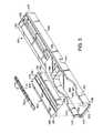
図2〜図6は、図1の装置100と共に使用するための、本開示に従って構築された新規で改良されたトレイアセンブリ200の例示的な実施態様を示す。図1の装置100は、試薬カセット122または試薬片145のような液体キャリヤ上に配置された体液サンプルのような液体サンプルを光学的に検査するための反射分光器である。トレイアセンブリ200は、支持トレイ202と、この支持トレイ内に、試薬カセット122を保持するべく適合された第1の面206、試薬片146を保持するべく適合された第2の面208の一方に嵌合する挿入部204とを備えており、上記第2の面は、試薬カセット122と試薬片146の一方を挿入部204により支持トレイ202内に保持することができるよう上方に向いている。Detailed Description of Exemplary Embodiments FIGS. 2-6 illustrate an exemplary embodiment of a new and improved
しかしながら、図2〜図6の新規および改良されたトレイアセンブリ200について説明する前に、まず背景情報を提供するために、図11〜図14で示される従来技術について説明する。図11は、体液サンプルのような液体サンプルを光学的に検査するための、反射分光器のような検査装置10を示す。装置10は、図18と図19でも示される支持トレイを有している。図11に示されるこの特定の装置10は、ニューヨーク州、TarrytownのBayer社Diagnostics Divisionより販売されているCLINITEK(登録商標)50 Urine Chemistry Analyzerである。装置10については、本開示の譲受人に譲渡され、本願明細書に参照により組込まれている米国特許第5,654,803号、第5,945,341号、および第6,239,445号においてより詳細に記述されている。 However, prior to describing the new and improved
検査装置10は、使用者が入力を行うための一体型キーボード12と、検査装置10の操作に関連した様々なメッセージを使用者に対して表示する視覚ディスプレイ16とを装備している。検査装置10はさらに、支持トレイ20を内部に引き込むための開口部18が形成されたハウジング17を有する。図11と図12が示すように、支持トレイ20は、第1の種類の液体キャリヤまたは取り外し可能な挿入物を収容するように適合されており、また支持トレイ20は試薬カセット22の形態であってよい。 The
試薬カセット22は、例えば妊娠検査を従来の方法で実施するための、使い捨て可能な一回使用のカセットであってよい。試薬カセット22は、例えば尿のような体液サンプルを配置するための、上方の面26に形成された開口部またはウェル24を設けている。試薬カセット22の内部には、ウェル24内に配置した体液サンプルに反応しうる試薬片(図示せず)を備えている。試験の結果により試薬片の色が変化するが(例えば色付きの縞模様が現れる)、この色の変化の判断は、試薬カセット22の上方面26に形成された窓28を通してこの試薬片を見ることで行うことができる。 The
図12に示すように、支持トレイ20は、試薬カセット22を内部に配置できる寸法の矩形凹部30を備えている。図11と図12が示すように、試薬カセット22は、凹部30よりも長いため、矩形カセット22を凹部30内部に配置した場合、試薬カセット22の一部が支持トレイ20の端部を越えて外方へ延び、これにより、使用者は矩形カセット22のこの外方へ延びた端部を把持し、凹部30から引き上げて取り外すことができる。 As shown in FIG. 12, the
図12を参照すると、凹部30の上方面32は、例えばピンの形状であってよい複数の上方へ延びた配置部材34を備えている。試薬カセット22を支持トレイ20内に配置すると、試薬カセット22の底面に形成された複数の孔または穴(図示せず)内に位置決めされ、配置部材34が、試薬カセット22が凹部30から誤って滑落してしまうことを防止する。支持トレイ20は、従来の方法で較正を容易にするようにその上方面に配置された、例えば白色のようなある一定の色をした従来型の較正チップ38を有してもよい。 Referring to FIG. 12, the
図13を参照すると、支持トレイ20はまた、試薬片ホルダ40の形状であってよい、第2の種類の液体キャリヤまたは取り外し可能な挿入物を収容するように適合されている。試薬片ホルダ40の外寸法は、試薬片ホルダ40も凹部30内に嵌合できるようにするために、一般に試薬カセット22の外寸法と同一である。試薬カセット22に関連して上述したように、試薬片ホルダ40はその底面に形成された複数の孔または穴(図示せず)を備えており、これらは、試薬片ホルダ40が凹部30から誤って滑落することを防止するように、配置部材34を収容するために位置決めされている。 Referring to FIG. 13, the
図13に示すように、試薬片ホルダ40は凹部30よりも長いため、試薬片ホルダ40を凹部30内に配置すると、試薬片ホルダ40の一部が支持トレイ20の端部を越えて外方に延び、これにより、使用者は試薬片ホルダ40のこの外方に延びた端部を把持し、凹部30からこれを引き上げて取り外すことができる。 As shown in FIG. 13, since the
試薬片ホルダ40は、その内部に形成され、試薬片46の形状と一致する寸法の中央経路43を備えており、この例を図14に示す。試薬片ホルダ40は、体液サンプルによる支持トレイ20の汚染の可能性を低減するために、試薬片ホルダ40の外縁周囲に配置された上昇したリップ部44を備えていてよい。 The
図14を参照すると、試薬片46は、上に多数の試薬パッド50が固定される薄い非反応性基板48を備えていてよい。各試薬パッド50は、それぞれの試薬をしみ込ませた、比較的高い吸収率を有する材料で構成することができ、試薬および試薬パッド50の各々は、実施する特定の試験に関連している。尿分析試験を実施する場合、この検査は例えば、尿中の白血球の試験、尿のpHの試験、尿中の血液の試験、その他を含むことができる。各試薬パッド50が尿サンプルと接触すると、パッドの色が、使用される試薬および尿サンプルの特徴に従い、時間の経過と共に変化する。例えば試薬片46は、ニューヨーク州、TarrytownのBayer社のDiagnostics Divisionより市販されているMULTISTIX(登録商標)試薬片であってよい。 Referring to FIG. 14, the
再び図11を参照すると、検査手順中に、支持トレイ20は、図11に示した外方へ延びた位置と、トレイ20が検査装置10のハウジング17内部に引き込まれる光学検査位置との間で移動する。試薬カセット22と試薬片ホルダ40が同一の外寸法を有し、支持トレイ20の凹部30内に嵌合するので、この検査装置10は、複数の試薬カセット22と複数の試薬片46に対して、使用者の所望の任意の順序において光学検査を実施するために使用できる。 Referring back to FIG. 11, during the inspection procedure, the
検査装置10を使用する際、使用者は、ウェル24内に体液サンプルを入れ、その後、支持トレイ20に形成されたカセット22を凹部30内に配置して、光学検査のための試薬カセット22を準備することができる。次に、使用者がキーボード12上の開始ボタン14を押して、制御装置100に支持トレイ20を内方へ引き込ませることで、試薬カセット22の窓28が光源108によって照明され、検出装置が1つ以上の反射信号を生成できるようになる。反射信号が生成し、制御装置によって処理された後に、試験結果がディスプレイ16上に表示され、および/またはプリンタ11によって印刷される。 When using the
1つ以上の光学検査試験を1枚の試薬片46に対して実施するためには、使用者は支持トレイの凹部30から試薬カセット22を取り出し、カセット22を廃棄し、試薬片ホルダ40を支持トレイ20の凹部30内に配置する。 To perform one or more optical inspection tests on a
光学検査用の試薬片46を準備するために、使用者は試薬片46を検査対象の体液サンプルに浸漬させて試薬パッド50にサンプルを浸潤させるか、またはパッド50にサンプルを塗布することができる。使用者は、試薬片46の片面を拭って余剰の液体を除いた後に、この試薬片46をホルダ40の中央経路43内に配置し、開始キー14を押して試薬片46の光学検査を開始する。次に、試薬片ホルダ40がハウジング17内に自動的に引き込まれ、検査装置10内の複数の位置に連続的に位置決めされることにより、検査位置で試薬パッド50の各々が光学的に検査される。 In order to prepare the
異なる種類の液体キャリヤと共に使用するように適合された支持トレイ20を提供することで、使用者による液体キャリヤの迅速かつ簡便な変更が可能になり、その一方で、検査装置が異なる種類の液体担持機構を光学的に検査できるようになる。ある種類の液体キャリヤを別の種類の液体キャリヤと交換するために、支持トレイ20を検査装置10から取りはずす必要はない点に留意すべきである。 Providing a
図2〜図6に示されている本開示のトレイアセンブリ200は、図11〜図13に示したトレイアセンブリ20を改良したものであり、また、図11の検査装置10と共に、図11〜図13のトレイアセンブリ20と類似の方法にて使用できる。図1の検査装置100も、やはり図11の検査装置10の改良されたものであり、図11の検査装置10と同様に動作する。図1の改良された検査装置100は、本願明細書中で参照により組込まれている、付けで出願された同時係属中の米国特許出願第号(代理人事件番号BYRK−003)においてより詳細に記述されている。図11の検査装置10と類似している図1の検査装置100の構成要素には、同一の参照番号の前に“1”を付している。しかしながら、図1の検査装置100は、図11のキーボード12とディスプレイ画面16の代わりにタッチ画面ディスプレイ115を装備している。図1の検査装置100はまた、トレイアセンブリ200が開口部118よりも外に延びると開放するドア119を開口部118に設けている。The
使用中に、本開示のトレイアセンブリ200の挿入物204は、支持トレイ202から取り外し可能であり、トレイアセンブリ200と共に使用する試薬カセット122および試薬片146に従って、裏返して支持トレイ202内に再度挿入することができる。図2の試薬カセット122は、図12の試薬カセット22と類似しているため、これらの類似の要素には前に“1”を付加した参照番号を付けている。さらに、図3の試薬片146は、図14の試薬カセット46と類似しているため、これらの類似の要素には前に“1”を付加した参照番号を付けている。試薬カセット122と試薬片146は、支持トレイ202に直接接触しないが、その代わりに挿入物204によって支持されるため、支持トレイ202が試薬カセット122および試薬片146からの過剰の体液で汚染される可能性が少ない。あるいは、必要であれば、挿入物204を支持トレイ202から取り外し、余剰の体液を洗浄することもできる。さらに、支持トレイ202は、挿入物204を取り外した状態で容易に洗浄することができる。 During use, the
図2を参照すると、挿入物204の第1の面206は、試薬カセット122の第1の部分212を収容するように形状された凹部210を有する。使用者が挿入物204内で試薬カセット122を正しい向きにすることを確実にするために、挿入物204の第1の面206の凹部210の端部壁214は、試薬カセット122の第1の部分212の湾曲した端部壁216と合致するよう湾曲している。挿入物204には、凹部210の開放端部220にボス218a、218bがあり、このボスの各々は、挿入物204からの試薬カセット122の滑落を防止するために、試薬カセット122の切り込み部222a、222b内にそれぞれ収容される。あるいは、ボスを試薬カセット122上に備えたり、切り込み部を挿入物204に設けることができる。試薬カセット122が挿入物204内に正確に位置決めされると、試薬カセット122の第2の部分224は、凹部210の開放端部220を越えて外方へ延びる。試薬カセット122の第2の部分224は、試薬カセット122の切り込み部222a、222bによって試薬カセット122の第1の部分212から分離されている。図2からわかるように、試薬カセット122の第2の部分224は、試薬カセット122の第1の部分212よりも短いため、使用者は挿入物204内で試薬カセット122を正しい向きにすることがさらに確実になる。これに加え、試薬カセット122が挿入物204内に上下逆さの状態で挿入されてしまうことを防止するために、凹部210のボス218a、218bがわずかに異なる寸法または形状にて設けられ、さらに、ボス218a、218bと合致する試薬カセット122の切り込み部222a、222bもわずかに異なる寸法または形状で設けられている。 Referring to FIG. 2, the
図3を参照すると、挿入物204の第2の面208は、試薬片146を収容できる寸法の細長い経路226を備えている。挿入物204の第2の面208はまた、挿入物204の一端で細長い経路226を閉じる端部壁228も有し、端部壁228の上面は白色(あるいはその他の適切な色)になっているため、検査手順中に試薬片146が端部壁228と正確に接しているか否かを判断するために、図1の検査装置100に白い端部壁を用いることができる。 With reference to FIG. 3, the
図2〜図4、および図6に示すように、挿入物204の第1および第2の面206、208が反対方向に向き、挿入物204がまた、第1および第2の面206、208を接続する対向する第1および第2の端部230、232、そして第1および第2の面206、208を接続する対向する第1および第2の端部234、236も有し、対向する端部230、232の間に延びている。 As shown in FIGS. 2-4 and 6, the first and
図2〜図5に示すように、支持トレイ202は、対向する第1の端部238と第2の端部240、対向する第1の端部238と第2の端部240の間に延びており、さらに、挿入物204を収容するべく第1の端部238から延びた小室244を備えている上面242を含む。小室244は、挿入物204の第2の端部232と合致する端部壁246と、端部壁246から延び、挿入物204の対向する第1の側部234、第2の側部236と合致する対向する第1の端部壁248、第2の端部壁250を含む。 As shown in FIGS. 2 to 5, the
使用中に、使用者が挿入物204を支持トレイ202内で正しい向きにすることができるようにするために、挿入物204の対向する第1の端部230、第2の端部232は異なる形状を有する。図2〜図4、図6の例示的な実施態様においては、挿入物204の第1の端部230の形状は矩形であり、挿入物204の第2の端部232の形状は湾曲している。 In order to allow the user to orient the
図2〜図4を参照すると、支持トレイ202の上面242は、支持トレイ202の第2の端部240から延びている細長い経路252を備えており、支持トレイ202の細長い経路252内に白色の較正片(図示せず)を有している。支持トレイ202の上面242はまた、小室244の端部壁246の中心から延びた傾斜面256を有し、挿入物204の第1の面206、第2の面208が、挿入物204を小室244内に位置決めした際に支持トレイ202の傾斜面256と対応する谷間またはくぼみ部分258も含む。傾斜面256は、試薬カセット122と試薬片146の適切な光学機械検査を実施する上で助けとなる。 With reference to FIGS. 2-4, the
図2〜図5に示す例示的な実施態様では、支持トレイ202の小室244の側壁248、250は、挿入物204を小室244内に位置決めした際に挿入物204の側部234、236を把持できるようにするためのカットアウト部260を有する。支持トレイ202はさらに、小室244から延びた細長い案内部262を備えており、そして、図2〜図4、および図6に示すように、挿入物204の第1の面206、第2の面208は、挿入物204を小室244内に位置決めした際に支持トレイ202の細長い案内部262と対応する細長い案内部264を有する。案内部は、装置100からトレイアセンブリ200を滑らかに案内し、引き出し、引き込むのを補助するために、図1の装置100内に取り付けた車輪(図示せず)を収容する溝262、264を含む。挿入物204はまた、過剰の体液が挿入物204から流れ出し、支持トレイ202の案内部262へ(さらに装置100内へ)流れ落ちるのを防止するために、第1の面206、第2の面208の細長い案内部246に排液溝266を画定している。したがって、排液溝266は、挿入物204または試薬カセット122、あるいは試薬片146上の過剰の体液で装置100が汚染されることを防止するのに役立つ。 In the exemplary embodiment shown in FIGS. 2-5, the
図2、図3、および図5に最もよく示されるように、小室244は、小室244からの挿入物204の滑落を防止するために、挿入物204を小室244内に位置決めした際に挿入部204と係合する停止部268を有する。図示されているこの例示的な実施態様では、停止部268は、挿入物204を小室244内に位置決めした際に挿入物204の第1の端部230と係合するように位置決めされている。支持トレイ202はまた、第1の端部238から延び、リップ部272を有する平面部分270を含んでおり、上記リップ部272は、挿入物を小室244内に位置決めした際に、挿入物204からの過剰な液体の漏出を捕え、収容する。したがって、平面部分270とリップ部272も、挿入物204、試薬カセット122または試薬片146上に収容された過剰な体液が装置100を汚染するのを防止するのに助けとなる。 As best shown in FIGS. 2, 3, and 5, the
図2および図3に示すように、支持トレイ202の側壁250に切欠部274が設けられている。この切欠部274は、支持トレイ202を装置100内に挿入する際に、液体サンプルを図1の検査装置100の別の検出器で検出するために使用される。 As shown in FIGS. 2 and 3, a
図4に示すように、支持トレイ202はさらにカム面276を備えている。カム面276は、支持トレイ202を装置100から引き出す際に、図1の液体サンプル検査装置100のドア119を開放し、そして、支持トレイ202が装置100内に引き込まれるとドア119を閉じるように使用される。検出段階中にドア119を閉じることで、装置100内へ周囲の光が侵入して不都合な結果を招くことを防止する。図4の例示的な実施態様では、カム面276は、支持トレイ202の第1の側壁248から延びている。 As shown in FIG. 4, the
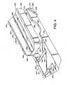
図7および図8は、本開示に従って構築された、図1の装置100とともに使用するための、トレイアセンブリ300の別の例示的な実施態様を示す。アセンブリ300は、支持トレイ302と、このトレイ内で移動するように収容された挿入物304とを含む。図7では、試薬片(図示せず)を挿入物304内に挿入でき、トレイアセンブリ300と共に使用できる1つの位置にある状態で挿入物304が示され、一方、図8では、試薬カセット(図示せず)を支持トレイ302内に挿入できる別の位置にある状態で挿入物304が示されている。挿入物304は、試薬片を収納できる寸法の細長い経路326と、挿入物304の一端で経路326を閉じる端部壁328とを有する。 7 and 8 illustrate another exemplary embodiment of a
支持トレイ302は、対向する第1の端部338および第2の端部340と、第1の端部と第2の端部の間に延び、支持トレイ302の第1の端部338で開放端部345から支持トレイ302の第2の端部340により近い端部壁346へと延びた小室344を備える上面342とを含む。挿入物304は、支持トレイ302の小室344内に可動的に支持され、図8に示される小室344の端部壁346に隣接する第1の位置と、図7に示される小室344の開放端部345に隣接する第2の位置との間で移動可能である。挿入物304が図8に示す第1の位置にある場合に、試薬カセット(図示せず)が、小室344内の、小室の開放端部345と挿入物304との間に挿入される。挿入物304の一端305に試薬カセットが接触する。 The
図7および図8の例示的な実施態様では、挿入物304は、支持トレイ302の小室344内の、第1および第2の位置の間で滑動可能に移動することができる。図示のように、支持トレイ302の小室の側壁348、350は経路380を備え、挿入物304の側部は、小室344内での挿入物304の滑動運動を案内する、経路380内に収容されたレール382を有している。挿入物304は支持トレイ302から取り外し不能である。 In the exemplary embodiment of FIGS. 7 and 8, the
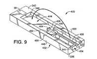
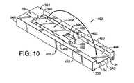
図1の装置100と共に使用する、本開示に従って構築されたトレイアセンブリ400のさらなる例示的な実施態様を図9、図10に示す。アセンブリ400は図7および図8のアセンブリ300と類似しているが、支持トレイ402の小室444内で、図10に示す第1の位置と図9に示す第2の位置の間で旋回可動である挿入物404を有する。トレイアセンブリ400は、挿入物404が第1の位置にある場合に、支持トレイ402の小室444内に試薬カセット(図示せず)を収容するように適合されている。トレイアセンブリ400は、挿入物404が第2の位置にある場合には、挿入物404の表面の細長い経路426内に試薬片(図示せず)を収容するように適合されている。 A further exemplary embodiment of a
挿入物404は、支持トレイ402の側壁448、450と挿入物404の蝶番492とを通って延びる2本のピン490によって支持トレイ402に旋回可能に取り付けられている。挿入物404は、支持トレイ302から取り外すことはできない。小室444の床の、挿入物404の蝶番492間に留め具494が固定されており、そして、試薬片が接触するための端部壁428と、試薬カセットが接触するための端部壁405とを提供する。 The
前述の説明から、当業者には本開示のさらに様々な変更および代替の態様が明白となるであろう。この説明は、例示としてのみ解釈されるべきであり、かつ、当業者に本開示を実施する最良の形態を教示することを目的とする。この構造および方法の詳細を、本開示の精神から逸脱することなく実質的に変更することができ、添付の請求項の範囲内に包括されるすべての変更の排他的使用は確保される。 From the foregoing description, various modifications and alternative embodiments of the present disclosure will be apparent to those skilled in the art. This description is to be construed as illustrative only and is for the purpose of teaching those skilled in the art the best mode of carrying out the disclosure. Details of this structure and method may be changed substantially without departing from the spirit of the present disclosure, and exclusive use of all changes encompassed within the scope of the appended claims is ensured.
Claims (69)
Translated fromJapanese液体サンプル検査装置内の検査場所内に挿入可能で、検査場所に位置決めすると装置の光源がその上に担持された液体サンプルを照明し、そして装置の検出器が液体サンプルからの光を受ける支持トレイ;および
支持トレイ内に支持され、かつ第1の種類の液体キャリヤを収容するように適合された第1の面と、第1の種類の液体キャリヤとは異なる第2の種類の液体キャリヤを収容するように適合された第2の面とを有する、挿入物
を含むトレイアセンブリ。A tray assembly for use with an apparatus adapted to inspect a liquid sample,
A support tray that can be inserted into an inspection location within a liquid sample inspection device, and when positioned at the inspection location, the light source of the device illuminates the liquid sample carried thereon, and the detector of the device receives light from the liquid sample And a first surface supported in the support tray and adapted to receive a first type of liquid carrier, and a second type of liquid carrier different from the first type of liquid carrier A tray assembly including an insert having a second surface adapted to do so.
第1および第2の面を接続する対向する第1および第2の端部;ならびに、
第1および第2の面を接続し、対向する端部間で延びる対向する第1および第2の側部を含み;そして、
支持トレイが、挿入物を収容するための小室を有する上面を含み、小室が、挿入物の第2の端部と合致する端部壁と、端部壁から延び、挿入物の対向する第1および第2の側部と合致する対向する第1および第2の側壁とを含む、請求項1記載のアセンブリ。The first and second sides of the insert are facing in opposite directions, and the insert is:
Opposing first and second ends connecting the first and second surfaces; and
Including opposing first and second sides connecting the first and second surfaces and extending between opposing ends; and
The support tray includes an upper surface having a chamber for receiving the insert, the chamber extending from the end wall to match the second end of the insert, and an opposing first of the insert. And an opposing first and second sidewalls that mate with the second side.
トレイアセンブリを内部に引き込み、かつ引き出す開口部;
トレイアセンブリを収容するための開口部内の検査場所;
開口部を開閉するためのドア;
支持トレイを検査場所に収容すると、トレイアセンブリ上に担持される液体サンプルを照明するための光源;および、
光源から発せられ、液体サンプルで反射された光を受けるための検出器;
を含む液体サンプル検査装置をさらに含み、
トレイアセンブリの支持トレイのカム面が検査装置のドアと相互作用して、支持トレイを装置から引き出す際にカム面がドアを開放し、支持トレイを装置内に引き込む際にドアを閉鎖する、システム。A system comprising a tray assembly according to claim 24, comprising:
An opening that pulls the tray assembly in and out;
Inspection location in the opening to accommodate the tray assembly;
Door to open and close the opening;
A light source for illuminating a liquid sample carried on the tray assembly when the support tray is received at the inspection site; and
A detector for receiving light emitted from a light source and reflected from a liquid sample;
Further comprising a liquid sample testing device comprising:
A system in which the cam surface of the support tray of the tray assembly interacts with the door of the inspection device, the cam surface opens the door when the support tray is pulled out of the device, and closes the door when the support tray is pulled into the device. .
トレイアセンブリを収容するための検査場所;
支持トレイを検査場所に収容すると、トレイアセンブリ上に担持された液体サンプルを照明するための光源;および、
光源から発せられ、液体サンプルで反射された光を受けるための検出器;を含む液体サンプル検査装置をさらに含むシステム。A system comprising the tray assembly of claim 1, comprising:
Inspection location for receiving tray assembly;
A light source for illuminating a liquid sample carried on the tray assembly when the support tray is received at the inspection site; and
A system further comprising a liquid sample inspection device, comprising: a detector for receiving light emitted from the light source and reflected from the liquid sample.
液体サンプル検査装置内部の検査場所内に挿入可能で、対向する第1および第2の端部と、対向する第1および第2の端部の間に延び、支持トレイの第1の端部における開放端部から、支持トレイの第2の端部により近い端部壁へと延びる小室を有する上面とを含む支持トレイ;および、
支持トレイの小室内に可動に支持され、小室の端部壁に隣接した第1の位置と小室の開放端部に隣接した第2の位置との間で移動可能な挿入物を含み、この挿入物が第1の位置にある際に、小室が、小室の開放端部に隣接した第1の種類の液体キャリヤを収容するように適合されており、そして、挿入物が、第1の種類の液体キャリヤとは異なる第2の種類の液体キャリヤを収容するように適合された面を含む、トレイアセンブリ。A tray assembly for use with an apparatus adapted to inspect a liquid sample,
Insertable into an inspection location within the liquid sample testing device and extending between the opposing first and second ends and the opposing first and second ends, at the first end of the support tray A support tray comprising an open end and an upper surface having a chamber extending from the open end to an end wall closer to the second end of the support tray; and
An insert that is movably supported in the chamber of the support tray and is movable between a first position adjacent to the end wall of the chamber and a second position adjacent to the open end of the chamber; The chamber is adapted to receive a first type of liquid carrier adjacent to the open end of the chamber when the object is in the first position, and the insert is of the first type. A tray assembly including a surface adapted to receive a second type of liquid carrier different from the liquid carrier.
トレイアセンブリを収容するための検査場所;
支持トレイを検査場所に収容する際に、トレイアセンブリ上に担持された液体サンプルを照明するための光源;そして
光源より発せられ、液体サンプルで反射された光を受けるための検出器;とを含む液体サンプル検査装置をさらに含むシステム。57. A system comprising the tray assembly of claim 56, comprising:
Inspection location for receiving tray assembly;
A light source for illuminating a liquid sample carried on the tray assembly when the support tray is received at the inspection site; and a detector for receiving light emitted from the light source and reflected by the liquid sample; A system further comprising a liquid sample testing device.
Applications Claiming Priority (3)
| Application Number | Priority Date | Filing Date | Title |
|---|---|---|---|
| US47528803P | 2003-06-03 | 2003-06-03 | |
| US10/821,441US7118713B2 (en) | 2003-06-03 | 2004-04-09 | Tray assembly for optical inspection apparatus |
| PCT/US2004/014574WO2004109339A2 (en) | 2003-06-03 | 2004-05-10 | Tray assembly for optical inspection apparatus |
Publications (3)
| Publication Number | Publication Date |
|---|---|
| JP2006526780Atrue JP2006526780A (en) | 2006-11-24 |
| JP2006526780A5 JP2006526780A5 (en) | 2007-06-28 |
| JP4436364B2 JP4436364B2 (en) | 2010-03-24 |
Family
ID=33493410
Family Applications (2)
| Application Number | Title | Priority Date | Filing Date |
|---|---|---|---|
| JP2006514336AExpired - LifetimeJP4436364B2 (en) | 2003-06-03 | 2004-05-10 | Tray assembly for optical inspection equipment |
| JP2006515090AExpired - LifetimeJP4850701B2 (en) | 2003-06-03 | 2004-06-03 | Light source wavelength correction |
Family Applications After (1)
| Application Number | Title | Priority Date | Filing Date |
|---|---|---|---|
| JP2006515090AExpired - LifetimeJP4850701B2 (en) | 2003-06-03 | 2004-06-03 | Light source wavelength correction |
Country Status (5)
| Country | Link |
|---|---|
| US (2) | US7118713B2 (en) |
| EP (2) | EP1633482B1 (en) |
| JP (2) | JP4436364B2 (en) |
| DK (1) | DK1633482T3 (en) |
| WO (2) | WO2004109339A2 (en) |
Cited By (3)
| Publication number | Priority date | Publication date | Assignee | Title |
|---|---|---|---|---|
| JP2012505380A (en)* | 2008-10-13 | 2012-03-01 | 紅電醫學科技股▲分▼有限公司 | Test strip reader and test strip used |
| WO2020096373A1 (en)* | 2018-11-08 | 2020-05-14 | 주식회사 녹십자엠에스 | Cholesterol measurement device |
| JP2023165585A (en)* | 2022-05-05 | 2023-11-16 | 緯創資通股▲ふん▼有限公司 | optical detection device |
Families Citing this family (22)
| Publication number | Priority date | Publication date | Assignee | Title |
|---|---|---|---|---|
| JP2007507716A (en)* | 2003-10-03 | 2007-03-29 | バイエル・ヘルスケア・エルエルシー | Correction of reflectance measurement accuracy |
| JP4150323B2 (en)* | 2003-10-29 | 2008-09-17 | 浜松ホトニクス株式会社 | Immunochromatographic test strip reader, cartridge used therefor, and immunochromatographic test strip inspection system |
| US7847946B2 (en) | 2005-05-18 | 2010-12-07 | Siemens Healthcare Diagnostics Inc. | Verification apparatus and methods for optical inspection machine |
| US20070211965A1 (en)* | 2006-03-07 | 2007-09-13 | Helbing Rene P | Hand-held diagnostic systems and methods of use thereof |
| WO2008086137A1 (en)* | 2007-01-08 | 2008-07-17 | 3M Innovative Properties Company | Device for the qualification of cooking oils, and methods |
| USD584975S1 (en)* | 2008-01-16 | 2009-01-20 | Ese Gmbh | Analytical sample detection device |
| EP2260299A4 (en)* | 2008-03-04 | 2011-12-14 | 3M Innovative Properties Co | Monitoring of frying oil quality using combined optical interrogation methods and devices |
| JP2011513750A (en)* | 2008-03-04 | 2011-04-28 | スリーエム イノベイティブ プロパティズ カンパニー | Method and device for monitoring the quality of frying oil |
| WO2010048277A2 (en) | 2008-10-21 | 2010-04-29 | Bayer Healthcare Llc | Optical auto-calibration method |
| DE102008064389A1 (en)* | 2008-12-22 | 2010-06-24 | Giesecke & Devrient Gmbh | Method and device for detecting optical properties of a value document |
| KR101144830B1 (en)* | 2010-09-10 | 2012-05-11 | 주식회사 세라젬메디시스 | Assay apparatus |
| KR101240963B1 (en)* | 2011-03-25 | 2013-03-11 | (주)미코바이오메드 | Optical-sensor strip and apparatus having the strip |
| CN102662056A (en)* | 2012-05-24 | 2012-09-12 | 蓝十字生物药业(北京)有限公司 | Immune colloidal gold test card with anti-discharging protection shell |
| DE202012103003U1 (en)* | 2012-08-09 | 2012-09-03 | Seramun Diagnostica Gmbh | Apparatus for measuring sample determination, measuring apparatus and kit with sample modules |
| US10101342B2 (en) | 2014-02-12 | 2018-10-16 | Church & Dwight Co., Inc. | Devices and methods for electronic analyte assaying |
| CN204255956U (en)* | 2014-10-29 | 2015-04-08 | 杭州中翰盛泰生物技术有限公司 | A kind of full-automatic real-time test instrument pick-up unit |
| WO2017058788A1 (en)* | 2015-09-29 | 2017-04-06 | Polymer Technology Systems, Inc. | Systems and methods for a lateral flow test strip holder |
| USD824534S1 (en)* | 2017-06-19 | 2018-07-31 | Integra Biosciences Ag | Reagent reservoir liner |
| USD840549S1 (en)* | 2017-06-19 | 2019-02-12 | Integra Biosciences Ag | Reagent reservoir kit |
| US20200033260A1 (en)* | 2018-07-25 | 2020-01-30 | Pauleologos Cusulos | Coagulation and aggregation refracted light indexing device and method |
| US20230044723A1 (en) | 2020-01-16 | 2023-02-09 | Leadway (Hk) Limited | Object stage and transfer platform for biological sample analyzer, and biological sample analyzer |
| CN113985054A (en)* | 2021-11-25 | 2022-01-28 | 基蛋生物科技股份有限公司 | Card feeding device and in-vitro diagnostic equipment |
Family Cites Families (21)
| Publication number | Priority date | Publication date | Assignee | Title |
|---|---|---|---|---|
| DE2443358C3 (en)* | 1974-09-11 | 1978-08-24 | Mkt Moderne Kuechentechnik Gmbh & Co Kg, 7444 Beuren | Combined contact grill and baking device |
| US4566798A (en)* | 1983-11-10 | 1986-01-28 | Eastman Kodak Company | Method for calibrating a reflectometer containing black and white references displaced from the sample position |
| JPH0789080B2 (en)* | 1986-06-02 | 1995-09-27 | ミノルタ株式会社 | Spectrometer |
| US5175697A (en)* | 1986-06-02 | 1992-12-29 | Minolta Camera Kabushiki Kaisha | Spectrophotometer for accurately measuring light intensity in a specific wavelength region |
| JP3119528B2 (en)* | 1992-05-15 | 2000-12-25 | 株式会社豊田中央研究所 | Scanner spectral colorimeter |
| JP3091929B2 (en)* | 1992-05-28 | 2000-09-25 | 日本光電工業株式会社 | Pulse oximeter |
| US5359192A (en)* | 1992-06-10 | 1994-10-25 | Quantic Industries Inc. | Dual-wavelength low-power built-in-test for a laser-initiated ordnance system |
| JP3212779B2 (en) | 1993-11-12 | 2001-09-25 | 富士写真フイルム株式会社 | Method for compensating for differences in the spectrometer of an optical analyzer |
| US5685301A (en)* | 1995-06-16 | 1997-11-11 | Ohmeda Inc. | Apparatus for precise determination of operating characteristics of optical devices contained in a monitoring probe |
| US6399023B1 (en)* | 1996-04-16 | 2002-06-04 | Caliper Technologies Corp. | Analytical system and method |
| US5654803A (en)* | 1996-05-09 | 1997-08-05 | Bayer Corporation | Apparatus and method for determination of non-hemolyzed levels of occult blood in urine |
| US5879294A (en) | 1996-06-28 | 1999-03-09 | Hutchinson Technology Inc. | Tissue chromophore measurement system |
| US5945341A (en)* | 1996-10-21 | 1999-08-31 | Bayer Corporation | System for the optical identification of coding on a diagnostic test strip |
| US6394952B1 (en)* | 1998-02-03 | 2002-05-28 | Adeza Biomedical Corporation | Point of care diagnostic systems |
| US5995236A (en) | 1998-04-13 | 1999-11-30 | Mit Development Corporation | Blood fluid characteristics analysis instrument |
| US6239445B1 (en)* | 1999-03-01 | 2001-05-29 | Bayer Corporation | Optical inspection apparatus with removable inserts |
| JP3819187B2 (en)* | 1999-09-28 | 2006-09-06 | 富士写真フイルム株式会社 | Spectral estimation method and spectral estimation system for spectral reflectance of multiband image |
| EP1118859A2 (en)* | 2000-01-21 | 2001-07-25 | Wako Pure Chemical Industries Ltd | A test device for a multi-items test and the method for producing the same as well as measuring instrument for the test device |
| AU2001252933A1 (en) | 2000-03-24 | 2001-10-08 | Umm Electronics, Inc. | Symmetric optical analysis device |
| EP1307708B1 (en)* | 2000-08-11 | 2007-07-11 | Elekon Industries, Inc. | System and method for a self-calibrating non-invasive sensor |
| JP2003057115A (en)* | 2001-08-14 | 2003-02-26 | Nireco Corp | Ink color measuring device for color printing press |
- 2004
- 2004-04-09USUS10/821,441patent/US7118713B2/ennot_activeExpired - Lifetime
- 2004-05-10DKDK04785691.9Tpatent/DK1633482T3/enactive
- 2004-05-10EPEP04785691.9Apatent/EP1633482B1/ennot_activeExpired - Lifetime
- 2004-05-10JPJP2006514336Apatent/JP4436364B2/ennot_activeExpired - Lifetime
- 2004-05-10WOPCT/US2004/014574patent/WO2004109339A2/enactiveApplication Filing
- 2004-06-03WOPCT/US2004/017340patent/WO2004109261A1/enactiveSearch and Examination
- 2004-06-03JPJP2006515090Apatent/JP4850701B2/ennot_activeExpired - Lifetime
- 2004-06-03EPEP04754043.0Apatent/EP1634058B1/ennot_activeExpired - Lifetime
- 2004-06-03USUS10/560,440patent/US7254503B2/ennot_activeExpired - Lifetime
Cited By (6)
| Publication number | Priority date | Publication date | Assignee | Title |
|---|---|---|---|---|
| JP2012505380A (en)* | 2008-10-13 | 2012-03-01 | 紅電醫學科技股▲分▼有限公司 | Test strip reader and test strip used |
| WO2020096373A1 (en)* | 2018-11-08 | 2020-05-14 | 주식회사 녹십자엠에스 | Cholesterol measurement device |
| CN112997066A (en)* | 2018-11-08 | 2021-06-18 | 株式会社绿十字Ms | Cholesterol measuring device |
| US12061192B2 (en) | 2018-11-08 | 2024-08-13 | Green Cross Medical Science | Cholesterol measurement device |
| JP2023165585A (en)* | 2022-05-05 | 2023-11-16 | 緯創資通股▲ふん▼有限公司 | optical detection device |
| JP7390446B2 (en) | 2022-05-05 | 2023-12-01 | 緯創資通股▲ふん▼有限公司 | optical detection device |
Also Published As
| Publication number | Publication date |
|---|---|
| US7254503B2 (en) | 2007-08-07 |
| WO2004109339A2 (en) | 2004-12-16 |
| JP4436364B2 (en) | 2010-03-24 |
| DK1633482T3 (en) | 2018-05-07 |
| EP1633482A2 (en) | 2006-03-15 |
| US20040247491A1 (en) | 2004-12-09 |
| EP1633482A4 (en) | 2008-06-25 |
| JP4850701B2 (en) | 2012-01-11 |
| EP1634058B1 (en) | 2014-05-07 |
| US20060139649A1 (en) | 2006-06-29 |
| US7118713B2 (en) | 2006-10-10 |
| WO2004109261A1 (en) | 2004-12-16 |
| EP1633482B1 (en) | 2018-01-17 |
| EP1634058A1 (en) | 2006-03-15 |
| WO2004109339A3 (en) | 2005-06-16 |
| JP2006526787A (en) | 2006-11-24 |
Similar Documents
| Publication | Publication Date | Title |
|---|---|---|
| JP4436364B2 (en) | Tray assembly for optical inspection equipment | |
| JP4749526B2 (en) | Optical inspection apparatus having a detachable insert | |
| US12146835B2 (en) | Calibration method for reagent card analyzers | |
| JP4890699B2 (en) | Analytical apparatus and method for measuring sample quality | |
| JP2006526788A (en) | Verification apparatus and method for optical inspection equipment | |
| US7847946B2 (en) | Verification apparatus and methods for optical inspection machine | |
| US9612249B2 (en) | Reduction of false positive on reagent test devices | |
| JP2023539444A (en) | Circuit board with built-in light source | |
| US20070071641A1 (en) | Tray assembly for optical inspection apparatus | |
| US20060257284A1 (en) | Verification device and method for optical inspection machine | |
| JP2005189034A (en) | Pipette device and analyzer equipped with the same | |
| WO2019073622A1 (en) | Pipette tip for inspection and pipette-type inspection device using said pipette tip for inspection | |
| JP2025524839A (en) | Analyzer with transparent shield for protecting the imaging system |
Legal Events
| Date | Code | Title | Description |
|---|---|---|---|
| A521 | Request for written amendment filed | Free format text:JAPANESE INTERMEDIATE CODE: A523 Effective date:20070508 | |
| A621 | Written request for application examination | Free format text:JAPANESE INTERMEDIATE CODE: A621 Effective date:20070508 | |
| A131 | Notification of reasons for refusal | Free format text:JAPANESE INTERMEDIATE CODE: A131 Effective date:20090324 | |
| A521 | Request for written amendment filed | Free format text:JAPANESE INTERMEDIATE CODE: A523 Effective date:20090624 | |
| A131 | Notification of reasons for refusal | Free format text:JAPANESE INTERMEDIATE CODE: A131 Effective date:20090804 | |
| A521 | Request for written amendment filed | Free format text:JAPANESE INTERMEDIATE CODE: A523 Effective date:20091027 | |
| TRDD | Decision of grant or rejection written | ||
| A01 | Written decision to grant a patent or to grant a registration (utility model) | Free format text:JAPANESE INTERMEDIATE CODE: A01 Effective date:20091201 | |
| A01 | Written decision to grant a patent or to grant a registration (utility model) | Free format text:JAPANESE INTERMEDIATE CODE: A01 | |
| A61 | First payment of annual fees (during grant procedure) | Free format text:JAPANESE INTERMEDIATE CODE: A61 Effective date:20091225 | |
| R150 | Certificate of patent or registration of utility model | Ref document number:4436364 Country of ref document:JP Free format text:JAPANESE INTERMEDIATE CODE: R150 Free format text:JAPANESE INTERMEDIATE CODE: R150 | |
| FPAY | Renewal fee payment (event date is renewal date of database) | Free format text:PAYMENT UNTIL: 20130108 Year of fee payment:3 | |
| FPAY | Renewal fee payment (event date is renewal date of database) | Free format text:PAYMENT UNTIL: 20130108 Year of fee payment:3 | |
| R250 | Receipt of annual fees | Free format text:JAPANESE INTERMEDIATE CODE: R250 | |
| R250 | Receipt of annual fees | Free format text:JAPANESE INTERMEDIATE CODE: R250 | |
| R250 | Receipt of annual fees | Free format text:JAPANESE INTERMEDIATE CODE: R250 | |
| R250 | Receipt of annual fees | Free format text:JAPANESE INTERMEDIATE CODE: R250 | |
| R250 | Receipt of annual fees | Free format text:JAPANESE INTERMEDIATE CODE: R250 | |
| R250 | Receipt of annual fees | Free format text:JAPANESE INTERMEDIATE CODE: R250 | |
| R250 | Receipt of annual fees | Free format text:JAPANESE INTERMEDIATE CODE: R250 | |
| R250 | Receipt of annual fees | Free format text:JAPANESE INTERMEDIATE CODE: R250 | |
| R250 | Receipt of annual fees | Free format text:JAPANESE INTERMEDIATE CODE: R250 | |
| R250 | Receipt of annual fees | Free format text:JAPANESE INTERMEDIATE CODE: R250 | |
| R250 | Receipt of annual fees | Free format text:JAPANESE INTERMEDIATE CODE: R250 | |
| R250 | Receipt of annual fees | Free format text:JAPANESE INTERMEDIATE CODE: R250 | |
| EXPY | Cancellation because of completion of term |