JP2006521904A - Implant device and its use - Google Patents
Implant device and its useDownload PDFInfo
- Publication number
- JP2006521904A JP2006521904AJP2006509680AJP2006509680AJP2006521904AJP 2006521904 AJP2006521904 AJP 2006521904AJP 2006509680 AJP2006509680 AJP 2006509680AJP 2006509680 AJP2006509680 AJP 2006509680AJP 2006521904 AJP2006521904 AJP 2006521904A
- Authority
- JP
- Japan
- Prior art keywords
- cannula
- actuator
- angled
- flexible actuator
- handle
- Prior art date
- Legal status (The legal status is an assumption and is not a legal conclusion. Google has not performed a legal analysis and makes no representation as to the accuracy of the status listed.)
- Granted
Links
- 239000007943implantSubstances0.000titleclaimsdescription118
- 238000000034methodMethods0.000claimsdescription24
- 239000003814drugSubstances0.000claimsdescription16
- 238000003780insertionMethods0.000claimsdescription16
- 230000037431insertionEffects0.000claimsdescription16
- 238000003825pressingMethods0.000claimsdescription5
- 239000003550markerSubstances0.000claimsdescription2
- 239000003094microcapsuleSubstances0.000claimsdescription2
- 229940124597therapeutic agentDrugs0.000claimsdescription2
- 230000000717retained effectEffects0.000abstractdescription2
- 230000033001locomotionEffects0.000description14
- 239000008188pelletSubstances0.000description13
- 229940079593drugDrugs0.000description11
- 239000000463materialSubstances0.000description9
- 238000007920subcutaneous administrationMethods0.000description8
- 239000003433contraceptive agentSubstances0.000description5
- 230000002254contraceptive effectEffects0.000description4
- 230000036512infertilityEffects0.000description4
- 208000014674injuryDiseases0.000description4
- 229920003023plasticPolymers0.000description4
- 230000008733traumaEffects0.000description4
- 241001465754MetazoaSpecies0.000description3
- 239000002033PVDF binderSubstances0.000description3
- 230000008901benefitEffects0.000description3
- 239000002775capsuleSubstances0.000description3
- 239000005556hormoneSubstances0.000description3
- 229940088597hormoneDrugs0.000description3
- 239000004033plasticSubstances0.000description3
- 229920002981polyvinylidene fluoridePolymers0.000description3
- 210000003813thumbAnatomy0.000description3
- RJKFOVLPORLFTN-LEKSSAKUSA-NProgesteroneChemical classC1CC2=CC(=O)CC[C@]2(C)[C@@H]2[C@@H]1[C@@H]1CC[C@H](C(=O)C)[C@@]1(C)CC2RJKFOVLPORLFTN-LEKSSAKUSA-N0.000description2
- 239000004699Ultra-high molecular weight polyethyleneSubstances0.000description2
- 208000027418Wounds and injuryDiseases0.000description2
- 239000011248coating agentSubstances0.000description2
- 238000012377drug deliveryMethods0.000description2
- 210000003811fingerAnatomy0.000description2
- 239000000017hydrogelSubstances0.000description2
- 238000000465mouldingMethods0.000description2
- 239000008177pharmaceutical agentSubstances0.000description2
- 229920000642polymerPolymers0.000description2
- 239000000583progesterone congenerSubstances0.000description2
- 229920002379silicone rubberPolymers0.000description2
- 239000004945silicone rubberSubstances0.000description2
- 238000001356surgical procedureMethods0.000description2
- 230000001225therapeutic effectEffects0.000description2
- 229920000785ultra high molecular weight polyethylenePolymers0.000description2
- 241000283690Bos taurusSpecies0.000description1
- 241001631457CannulaSpecies0.000description1
- 229910001069Ti alloyInorganic materials0.000description1
- 239000000443aerosolSubstances0.000description1
- 230000009286beneficial effectEffects0.000description1
- 239000008280bloodSubstances0.000description1
- 210000004369bloodAnatomy0.000description1
- 238000005266castingMethods0.000description1
- 238000000576coating methodMethods0.000description1
- 238000011109contaminationMethods0.000description1
- 229940124558contraceptive agentDrugs0.000description1
- 238000011161developmentMethods0.000description1
- 230000018109developmental processEffects0.000description1
- 201000010099diseaseDiseases0.000description1
- 208000037265diseases, disorders, signs and symptomsDiseases0.000description1
- 238000004090dissolutionMethods0.000description1
- 239000000499gelSubstances0.000description1
- 238000002513implantationMethods0.000description1
- 238000001990intravenous administrationMethods0.000description1
- 238000005304joiningMethods0.000description1
- 239000007788liquidSubstances0.000description1
- 238000003754machiningMethods0.000description1
- 239000000203mixtureSubstances0.000description1
- 239000002245particleSubstances0.000description1
- 230000037368penetrate the skinEffects0.000description1
- 230000037390scarringEffects0.000description1
- 230000035939shockEffects0.000description1
- 230000000087stabilizing effectEffects0.000description1
- 229910001220stainless steelInorganic materials0.000description1
- 150000003431steroidsChemical class0.000description1
- 229940126585therapeutic drugDrugs0.000description1
- 238000003466weldingMethods0.000description1
Images


Classifications
- A—HUMAN NECESSITIES
- A61—MEDICAL OR VETERINARY SCIENCE; HYGIENE
- A61B—DIAGNOSIS; SURGERY; IDENTIFICATION
- A61B17/00—Surgical instruments, devices or methods
- A61B17/34—Trocars; Puncturing needles
- A—HUMAN NECESSITIES
- A61—MEDICAL OR VETERINARY SCIENCE; HYGIENE
- A61M—DEVICES FOR INTRODUCING MEDIA INTO, OR ONTO, THE BODY; DEVICES FOR TRANSDUCING BODY MEDIA OR FOR TAKING MEDIA FROM THE BODY; DEVICES FOR PRODUCING OR ENDING SLEEP OR STUPOR
- A61M25/00—Catheters; Hollow probes
- A61M25/01—Introducing, guiding, advancing, emplacing or holding catheters
- A61M25/06—Body-piercing guide needles or the like
- A61M25/0612—Devices for protecting the needle; Devices to help insertion of the needle, e.g. wings or holders
- A—HUMAN NECESSITIES
- A61—MEDICAL OR VETERINARY SCIENCE; HYGIENE
- A61B—DIAGNOSIS; SURGERY; IDENTIFICATION
- A61B17/00—Surgical instruments, devices or methods
- A61B17/34—Trocars; Puncturing needles
- A61B17/3468—Trocars; Puncturing needles for implanting or removing devices, e.g. prostheses, implants, seeds, wires
- A—HUMAN NECESSITIES
- A61—MEDICAL OR VETERINARY SCIENCE; HYGIENE
- A61M—DEVICES FOR INTRODUCING MEDIA INTO, OR ONTO, THE BODY; DEVICES FOR TRANSDUCING BODY MEDIA OR FOR TAKING MEDIA FROM THE BODY; DEVICES FOR PRODUCING OR ENDING SLEEP OR STUPOR
- A61M37/00—Other apparatus for introducing media into the body; Percutany, i.e. introducing medicines into the body by diffusion through the skin
- A61M37/0069—Devices for implanting pellets, e.g. markers or solid medicaments
Landscapes
- Health & Medical Sciences (AREA)
- Life Sciences & Earth Sciences (AREA)
- Engineering & Computer Science (AREA)
- Animal Behavior & Ethology (AREA)
- Biomedical Technology (AREA)
- Heart & Thoracic Surgery (AREA)
- General Health & Medical Sciences (AREA)
- Public Health (AREA)
- Veterinary Medicine (AREA)
- Medical Informatics (AREA)
- Surgery (AREA)
- Anesthesiology (AREA)
- Hematology (AREA)
- Nuclear Medicine, Radiotherapy & Molecular Imaging (AREA)
- Dermatology (AREA)
- Molecular Biology (AREA)
- Pathology (AREA)
- Biophysics (AREA)
- Pulmonology (AREA)
- Infusion, Injection, And Reservoir Apparatuses (AREA)
- Prostheses (AREA)
- Electrotherapy Devices (AREA)
- Media Introduction/Drainage Providing Device (AREA)
- External Artificial Organs (AREA)
- Massaging Devices (AREA)
- Paper (AREA)
- Noodles (AREA)
- Disintegrating Or Milling (AREA)
- Absorbent Articles And Supports Therefor (AREA)
- Orthopedics, Nursing, And Contraception (AREA)
Abstract
Translated fromJapaneseDescription
Translated fromJapanese本発明は、全体的にインプラント装置と、患者の皮下にインプラント可能対象物を挿入する方法とに関するものである。具体的には、本発明は前記インプラント装置のベースに位置する角度のついたトラックにより、インプラント可能対象物解放の改善された制御を提供するインプラント装置に関するものである。 The present invention relates generally to an implant device and a method for inserting an implantable object under the skin of a patient. In particular, the present invention relates to an implant device that provides improved control of implantable object release by an angled track located at the base of the implant device.
薬物は、経口、静脈内投与、エアロゾールの吸入、表皮パッチ、皮下インプラントなど様々な方法で患者に送達することができる。選択される方法は、とりわけ患者で達成されるべき薬物または医薬品の望ましい治療濃度、および前記濃度が維持されなければならない時間によって変わる。 The drug can be delivered to the patient in a variety of ways including oral, intravenous administration, aerosol inhalation, epidermal patch, subcutaneous implant. The method selected will depend on, among other things, the desired therapeutic concentration of the drug or pharmaceutical agent to be achieved in the patient and the time that the concentration must be maintained.
最近発売された物質および医薬品は、薬物が長時間にわたりゆっくりと放出されるように、薬物が患者の皮下に皮下導入または皮下投与されるように開発されてきている。そのようなインプラントにより、薬物が数ヶ月または数年にわたり比較的均一な用量で投与されることが可能となる。この薬物の投与方法は、避妊薬の投与法として特に重要かつ一般的になっている。 Recently released materials and pharmaceuticals have been developed so that the drug is introduced subcutaneously or administered subcutaneously to the patient's skin so that the drug is released slowly over time. Such implants allow the drug to be administered in relatively uniform doses over months or years. This method of administering drugs has become particularly important and common as a method of administering contraceptives.
これまで、皮下インプラントおよび他の種類のインプラントは、カニューレと栓子(obdurator)を含む2部システムからなるトロカールシステムを利用して皮下挿入されてきた。まず、皮膚が切開され、カニューレと栓子が一緒に皮膚に挿入される。次に、前記栓子が引き抜かれ、インプラントを挿入するガイドとして前記カニューレが放置される。前記インプラントが、前記カニューレから挿入され、前記栓子を利用して前記インプラントを前記カニューレの末端へ押す。次に、前記栓子を利用して前記カニューレの外に前記インプラントを押し出す一方で、前記カニューレが引き抜かれ、前記インプラントがこれまで前記カニューレが占めていた溝に配置される。次に、前記カニューレおよび栓子が完全に引き抜かれ、前記インプラントが皮下に放置される。 In the past, subcutaneous implants and other types of implants have been inserted subcutaneously using a two-part trocar system that includes a cannula and obturator. First, the skin is incised and the cannula and obturator are inserted together into the skin. The obturator is then withdrawn, leaving the cannula as a guide for inserting the implant. The implant is inserted through the cannula and the obturator is used to push the implant to the distal end of the cannula. The obturator is then used to push the implant out of the cannula while the cannula is withdrawn and the implant is placed in the groove previously occupied by the cannula. The cannula and obturator are then completely withdrawn and the implant is left subcutaneously.
このトロカールの挿入プロセスには、調整しながら前記栓子を押し、前記カニューレを引き抜いて、前記インプラントを前記溝に挿入するため、かなりの専門的技術が必要である。これらの2つのプロセスが適切に調整されていないと、前記インプラントが前記組織に無理に押し込まれ、前記インプラントが挿入されるときにそれ自体が溝を作らなければならなくなる。前記インプラントを前記組織に無理に押し込むと、前記組織にさらに外傷ができ、また前記インプラントが前記栓子から働く力により損傷を受ける可能性がある。これは、特にハイドロジェルインプラントに当てはまる。切開用の外科用メスと、前記インプラントを放置するトロカールシステムとを用いて外科的に皮下インプラントを行うことができるが、そのような方法には医師または他の高度な訓練を受けた者が必要である。必要な操作技術が概してはるかに少ない、皮下インプラントを挿入する改良装置の最近の開発は、外科以外の医師または他のあまり技術のない者にも適しており、それによりインプラント手術に必要な時間が短くて済む。 This trocar insertion process requires considerable expertise to adjust and push the obturator, withdraw the cannula and insert the implant into the groove. If these two processes are not properly coordinated, the implant will be forced into the tissue and will itself create a groove when the implant is inserted. Forcing the implant into the tissue can cause further trauma to the tissue, and the implant can be damaged by the force exerted by the obturator. This is especially true for hydrogel implants. Subcutaneous implants can be performed surgically using an open scalpel and a trocar system to leave the implant, but such methods require a physician or other highly trained person It is. Recent developments of improved devices for inserting subcutaneous implants, which generally require much less manipulation techniques, are also suitable for non-surgery physicians or other less skilled personnel, thereby reducing the time required for implant surgery. It's short.
米国特許番号第4,105,030号では、動物に複数のペレット剤を皮下インプラントするために使用するインプラント装置について開示されている。前記装置は、片手インプラントシステムを提供し、インプラントを組織に無理に入れることで外傷が生じるリスクを低くし、雑菌混入も低減している。前記動物インプラント装置は、ハンドルと、インプラントされるペレット剤を含む針と、前記ペレット剤を前記針の外に押し出すための前記針の中に配置された棒とを含む。前記ペレット剤を含む前記針を皮下挿入すると、ハンドル上のバネが付いたバネ止めが外れ、前記針がバネによって自動的に引き抜かれ、ペレット剤が放置される。しかし、このインプラント装置のハンドル構造は、ウシなどの動物で使用するためにデザインされており、その大きさと形のため、ヒトでインプラントを皮下挿入するために利用することは難しいだろう。さらに、前記針は前記バネ止めが外れると自動的に引き込むため、この装置の前記針の動きを制御することができない。このインプラント装置の複雑なバネが付いた推進装置とバネ止めは、前記装置が動かなくなり、必要に応じてペレット剤を押し出すことができなくなる可能性が高い。 U.S. Pat. No. 4,105,030 discloses an implant device for use in subcutaneous implantation of multiple pellets in an animal. The device provides a one-handed implant system that reduces the risk of trauma caused by forcing the implant into the tissue and reduces contamination. The animal implant device includes a handle, a needle containing a pellet to be implanted, and a rod disposed within the needle for pushing the pellet out of the needle. When the needle containing the pellet is inserted subcutaneously, the spring stopper with the spring on the handle is released, the needle is automatically pulled out by the spring, and the pellet is left. However, the handle structure of this implant device is designed for use in animals such as cows, and because of its size and shape, it will be difficult to use for human subcutaneous insertion of implants. Furthermore, since the needle automatically retracts when the spring stop is released, the movement of the needle of this device cannot be controlled. The complex spring-loaded propulsion device and spring stop of this implant device are likely to stop the device from moving out of the pellet as needed.
皮下インプラントされる避妊ステロイドは通常、生物学的に不活性なポリマー(ポリマーの一部分は生物分解性である)に埋め込まれる。そのような物質から作られるペレット剤は、典型的には長く、断面が円筒状で、これらの物質の大きさは鉛筆の芯ほどの大きさである。前記物質は通常可塑性で、やや柔軟なものから非常に柔軟なものまである。例えば、いくつかの典型的避妊ペレット剤と、そのようなペレット剤を個別に皮下インプラントする装置について報告した、米国特許番号第4,451,253号を参照のこと。 Contraceptive steroids that are implanted subcutaneously are typically embedded in a biologically inert polymer (a portion of the polymer is biodegradable). Pellets made from such materials are typically long and cylindrical in cross section, and the size of these materials is as large as a pencil core. Such materials are usually plastic, ranging from somewhat flexible to very flexible. See, for example, US Pat. No. 4,451,253, which reported several typical contraceptive pellets and devices for subcutaneously implanting such pellets individually.
ペレット剤の大きさと形は、皮下インプラントからの特定薬物の送達率を決定するために重要である。皮下インプラントの大きさには実施上の配慮から制約がある。特に、インプラントの長さは通常限定される。典型的なインプラントは1.5(1 1/2)〜2インチほどの長さである。インプラントが長いほど、正確に放置することがより難しくなる。また、長いインプラントは破損しやすく、前記薬物送達率に影響する可能性があり、一般には、単純により扱いにくいことは外見からも明白である。このため、単一の長いペレット剤ではなく、複数の個別の短いインプラント用ペレット剤として、所望の量の薬物をインプラントすることが必要となる場合が多い。従って、医師または看護師が複数のペレット剤を迅速にインプラントことができ、患者に対する身体的外傷、精神的ショックが最小限である装置が望ましい。複数のインプラントを埋め込む場合、1つのインプラントが他のインプラントの溶解を邪魔しないように、前記インプラントを正確に放置する注意が必要である。 The size and shape of the pellet is important for determining the delivery rate of a specific drug from the subcutaneous implant. The size of the subcutaneous implant is limited due to practical considerations. In particular, the length of the implant is usually limited. A typical implant is about 1.5 (11/2) to 2 inches long. The longer the implant, the more difficult it is to leave accurately. Also, it is clear from the appearance that long implants are prone to breakage and can affect the drug delivery rate, and in general are simply more cumbersome. For this reason, it is often necessary to implant a desired amount of drug as a plurality of individual short implant pellets rather than a single long pellet. Therefore, a device that allows a doctor or nurse to quickly implant multiple pellets and minimizes physical trauma and psychological shock to the patient is desirable. When implanting multiple implants, care must be taken to leave the implant exactly so that one implant does not interfere with the dissolution of the other.
本発明の実施形態は、様々な医薬品をインプラントするために用いられる装置と、治療薬送達装置とを含む。そのようなインプラント可能対象物は、合成プロゲスチン避妊ホルモンを含むシリコンゴムカプセルやチューブなどを含む。前記フレキシブルなチューブは、血流に低用量のホルモンを徐々に放出することができるものである。 Embodiments of the present invention include devices used to implant various pharmaceutical agents and therapeutic agent delivery devices. Such implantable objects include silicone rubber capsules or tubes containing synthetic progestin contraceptive hormones. The flexible tube is capable of gradually releasing low doses of hormones into the bloodstream.
本発明の1つの実施形態は、インプラント可能対象物を患者に皮下挿入するためのインプラント装置であって、インプラント可能対象物の挿入時に前記装置を把持するためのハンドルと、前記ハンドルに接続したベースとを有する。前記ベースは、ポストと、カニューレと、角度のついたトラックに位置付けしたフレキシブルなアクチュエータとを有する。前記カニューレは、前記ポスト上に同軸上にかつ長手方向にスライド自在に設けられ、カニューラ内にインプラント可能対象物が保持される伸長位置と、前記カニューレからインプラント可能対象物が解放される引込位置との間でスライド自在である。前記ベースの角度のついたトラックに配置されたフレキシブルなアクチュエータは、スライドして前記カニューレの突起部と結合し、前記カニューレを伸長位置から引込位置に移動して、前記カニューレからインプラント可能対象物を解放するために利用され、前記アクチュエータはロック位置とロック解除位置との間で曲がる。 One embodiment of the invention is an implant device for subcutaneously inserting an implantable object into a patient, a handle for gripping the device upon insertion of the implantable object, and a base connected to the handle And have. The base includes a post, a cannula, and a flexible actuator positioned on an angled track. The cannula is coaxially and longitudinally slidable on the post, an extended position where the implantable object is held in the cannula, and a retracted position where the implantable object is released from the cannula It is slidable between. A flexible actuator located on the angled track of the base slides to couple with the cannula protrusion and moves the cannula from the extended position to the retracted position to remove the implantable object from the cannula. Used to release, the actuator bends between a locked position and an unlocked position.
前記カニューレを動かないようにし、それによってインプラント可能対象物の望ましくないあらゆる投与または挿入がされないようにするため、前記インプラント装置のフレキシブルなアクチュエータをロックすることができる。(前記アクチュエータが前記ハンドルに対して遠端のトラックにあるとき)前記フレキシブルなアクチュエータを第2の位置の中へ押すことで、前記アクチュエータのロック部分は、前記カニューレの引込みを防ぐようになる。前記ロックは、前記フレキシブルなアクチュエータを第1の位置へ交互に押すことにより解放することがでる。 In order to prevent movement of the cannula and thereby prevent any undesired administration or insertion of implantable objects, the flexible actuator of the implant device can be locked. By pushing the flexible actuator into the second position (when the actuator is in a track far from the handle), the locking portion of the actuator prevents the cannula from retracting. The lock can be released by alternately pushing the flexible actuator to a first position.
前記インプラント装置は、前記カニューレ内にさらに1若しくはそれ以上のインプラント可能対象物を含むことができる。前記インプラント装置は、前記アクチュエータおよびカニューレの動作によりインプラント可能対象物が投与された後、前記カニューレに連続的に送り込まれる複数のインプラント可能対象物を支えるためのカートリッジも含めることができる。前記カートリッジは、取外し自在に搭載することもでき、前記カニューレの中心の穴部と、平行なインプラント可能対象物を含む溝部(チャネル)とを有するものである。 The implant device can further include one or more implantable objects within the cannula. The implant device may also include a cartridge for supporting a plurality of implantable objects that are successively fed into the cannula after the implantable object is administered by operation of the actuator and cannula. The cartridge can also be detachably mounted and has a central hole in the cannula and a channel (channel) containing parallel implantable objects.
本発明のさらなる観点によれば、本発明のインプラント装置を備えた皮下インプラント可能対象物を挿入する方法は、前記カニューレ内に配置されたインプラント可能対象物とともに、患者の皮下に前記インプラント装置のカニューレを挿入する工程と、前記フレキシブルなアクチュエータを用いて角度のついたトラックに沿って前記カニューレを手動で引き込み、前記皮下に前記インプラント可能対象物を解放する工程を含む。次に、前記インプラント装置が前記患者から引き抜かれるか、または前記カニューレ内に配置されたカートリッジから別のインプラント可能対象物を続けて挿入することもできる。前記方法に用いられる前記インプラント装置は、ハンドルと、ベースと、角度のついたトラックに配置されたフレキシブルなアクチュエータと、スライド自在に結合するカニューレとを含む。 According to a further aspect of the present invention, a method for inserting a subcutaneously implantable object comprising the implant device of the present invention includes a cannula of the implant device subcutaneously in a patient along with the implantable object disposed within the cannula. And manually retracting the cannula along an angled track using the flexible actuator to release the implantable object subcutaneously. The implant device can then be withdrawn from the patient, or another implantable object can be subsequently inserted from a cartridge disposed within the cannula. The implant device used in the method includes a handle, a base, a flexible actuator disposed on an angled track, and a cannula that is slidably coupled.
本発明のさらに別の観点によれば、インプラント可能対象物を挿入し、滅菌状態を維持するキットには、ハンドルと前記ハンドルに接続したベースとを含むインプラント装置を含み、前記ベースは、ポストと、カニューレと、角度のついたトラックに配置されたフレキシブルなアクチュエータとを有し、前記カニューレは、前記ポスト上に同軸上に且つ長手方向にスライド自在であって、インプラント可能対象物が前記カニューレに保持される伸長位置と、前記インプラント可能対象物が前記カニューレから解放される引込位置との間でスライド自在であり、前記アクチュエータは、前記ベースの角度のついたトラックに配置され、前記カニューレの突起とスライド自在に結合し、前記カニューレを伸長位置から引込位置に動かして、前記カニューレから前記インプラント可能対象物を解放するために用いられるものである。さらに、前記キットは、患者の組織をインプラント用に切開する切開装置、前記インプラント挿入プロセスの滅菌状態を維持するための部品、および創傷包帯も含む。 According to yet another aspect of the invention, a kit for inserting an implantable object and maintaining sterility includes an implant device comprising a handle and a base connected to the handle, the base comprising a post and A cannula and a flexible actuator disposed in an angled track, the cannula being slidable coaxially and longitudinally on the post, wherein an implantable object is attached to the cannula. Slidable between an extended position to be retained and a retracted position in which the implantable object is released from the cannula, and the actuator is disposed on an angled track of the base, the protrusion of the cannula The cannula is moved from the extended position to the retracted position, And it is used to release the implantable object from Yure. The kit further includes an incision device for incising a patient's tissue for an implant, components for maintaining the sterility of the implant insertion process, and a wound dressing.
本発明のインプラント可能対象物とインプラント装置は、ゾル・ゲルコーティング剤でコーティングされたインプラントの挿入、またはハイドロジェルインプラントの挿入に有用と考えられる。前記活性薬物は、血液や組織などの水分の多い環境に置くと、前記インプラントまたは前記インプラント表面のコーティング剤からゆっくりと解放することができる。前記装置は、そのようなインプラントを埋め込むために利用することができる。 The implantable object and implant device of the present invention are considered useful for insertion of implants coated with a sol-gel coating agent, or insertion of hydrogel implants. The active drug can be slowly released from the implant or the coating surface of the implant surface when placed in a moist environment such as blood or tissue. The device can be utilized to implant such an implant.
本発明は、前記インプラント装置のベースにある角度のついたトラックにより、インプラント可能対象物の解放に関する改善された制御を提供し、インプラント可能対象物を挿入するインプラント装置に関する実施形態を提供する。前記フレキシブルなアクチュエータは前記角度のついたトラックに位置付けられ、それにより、制御不能な力が前記組織に外傷を生じさせ、前記インプラントを損傷する可能性があるために、前記インプラント可能対象物に係る力が前記組織に押し出されるのを防ぐのを助けるものである。 The present invention provides an improved control over the release of an implantable object by means of an angled track at the base of the implant apparatus and provides an embodiment for an implant apparatus for inserting an implantable object. The flexible actuator is positioned on the angled track so that an uncontrollable force can cause trauma to the tissue and damage the implant, thus affecting the implantable object. It helps to prevent force from being pushed into the tissue.
本構成および方法を説明する前に、記載されている特定の分子、組成、方法論、またはプロトコールが様々である可能性があるため、本発明はこれらに限定されないことは理解されるものとする。説明に使用される用語は、特定のバージョンまたは実施形態のみを説明することを目的としたものであり、前記添付の特許請求の範囲のみで限定される本発明の範囲を限定する意図はないことも理解されることとする。 Before describing the present configurations and methods, it is to be understood that the invention is not limited to the specific molecules, compositions, methodologies, or protocols described, as these may vary. The terminology used in the description is for the purpose of describing particular versions or embodiments only and is not intended to limit the scope of the invention, which is limited only by the appended claims. Will also be understood.
本明細書および添付の特許請求の範囲に用いられる単数形の「a」、「an」、および「the」は、文脈が明確に単数形であることを示していない限り、複数の言及も含めることも注意されるべきである。従って、例えば、「セル"cell"」という言及は1若しくはそれ以上のセルおよび当業者に周知の同等物に言及している。それ以外に定義しているのではない限り、本明細書に用いられるすべての技術的、科学的用語は、通常の当業者によって一般に理解されるものと同じ意味を有するものである。本明細書に説明したものと同様またはそれに相当するすべての方法および材料が、本発明の実施形態を実行するまたは検討するために用いることができるが、ここでは好適な方法、装置、および材料を説明する。本明細書で言及されたすべての文献は、この参照により本明細書に組み込まれるものである。本明細書では、先行発明に基づいたそのような開示に先行する権利がないことの承認として、本発明が解釈されるものでは全くない。 As used in this specification and the appended claims, the singular forms “a”, “an”, and “the” include plural references unless the context clearly dictates otherwise. It should also be noted. Thus, for example, reference to “a cell” refers to one or more cells and equivalents well known to those skilled in the art. Unless defined otherwise, all technical and scientific terms used herein have the same meaning as commonly understood by one of ordinary skill in the art. Although any methods and materials similar or equivalent to those described herein can be used in the practice or contemplated embodiments of the present invention, suitable methods, devices, and materials are described herein. explain. All documents mentioned in this specification are incorporated herein by this reference. Nothing herein is to be construed as an admission that there is no right to precede such disclosure based on the prior invention.
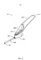
本発明では、例えば疾患を予防、治療、および診断する医薬品など、有益な薬物を含むインプラント可能対象物を皮下挿入するためのインプラント装置を提供する。本発明の1つの実施形態に沿った前記インプラント装置200は、図1に透視図で示されている。前記インプラント装置200は、ハンドル220と、移動可能な細長いカニューレ240(引込位置で示す)と、ポストロッド244(図3に示す)に沿って前記カニューレ240を動かすためのフレキシブルなアクチュエータ260(図3に示す)に接続したフレキシブルなアクチュエータボタン262と、ベース280とを含む。前記ベース280は、前記ハンドル端222の遠位にある。前記引込位置では、前記フレキシブルなアクチュエータボタン262が前記ハンドル端に向かって動くまたはスライドすることで、前記カニューレ240が前記ハンドルベース280の内部に引き込まれる。前記フレキシブルなアクチュエータボタン262は、前記カニューレ240の動作の軸または前記ポストロッド244(図3に示す)の軸に対して非平行な角度のついたトラック300により誘導される。前記カニューレ240は、前記ポストロッド244(図3に示す)およびカニューレガイド340を有するハウジングベース280に対してスライドするかまたは移動することができる。前記カニューレガイド340に向かう方向へ、および前記トラック300に沿って前記ハンドル220から離れるような前記フレキシブルなアクチュエータ260の動作により、前記カニューレ240が前記カニューレガイド340を通って伸長する。 The present invention provides an implant device for subcutaneously inserting an implantable object containing a beneficial drug, such as, for example, a medicament for preventing, treating, and diagnosing a disease. The
図2では、前記インプラント装置200は、前記カニューレ240が伸長位置で示されている。図2では、前記フレキシブルなアクチュエータボタン262が、前記ハンドル端222から遠位にあることが示されている。この位置では、前記フレキシブルなアクチュエータがロックされ、前記カニューレ240が引き抜きを予防、およびインプラント可能対象物が偶然にインプラントされることを予防することができる。前記カニューレガイド340から離れる方向へ、および前記角度のついたトラック300に沿って前記ハンドル方向への前記フレキシブルなアクチュエータボタン262の動作により、前記カニューレ240は引き込まれ、前記カニューレ240の穴部242内にインプラント可能対象物(図示せず)の解放が位置付けられる。 In FIG. 2, the
前記フレキシブルなアクチュエータの動作は角度のついた傾斜に沿って動き、この角度のついた傾斜により、ポストロッド軸に沿った前記カニューレ動作の制御における精度が高まる。これは、ユーザーにインプラント可能対象物の挿入を制御しやすくするという利点を提供する。 The movement of the flexible actuator moves along an angled ramp, which increases the accuracy in controlling the cannula motion along the post rod axis. This provides the advantage of making it easier for the user to control the insertion of the implantable object.
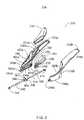
図3は、図1および2に示された実施形態の等角図の分解図が示されている。この図では、前記インプラント装置200が200aと200bの2つの部分で示され、これには第1および第2の部分220aおよび220bを有するハンドル220と、第1および第2の部分280aおよび280bを有するベース280と、第1および第2のカニューレガイド部分340aおよび340bを有するカニューレガイド340と、ハンドルの末端部分222aおよび222bを含むハンドル端222とを含む。前記角度のついたトラック300は、2つの対向する窪んだトラック300aおよび300bで形成され、前記インプラント装置の一部分200aおよび200bが組み立てられると、前記角度のついたトラック300を形成する。前記インプラント装置内のハンドル220は、フレキシブルなアクチュエータ溝248aの一部分(ハンドル220bの248bは図3には図示せず)であり、組み立てられると、前記組み立てられたインプラント装置のハンドル220内で、前記フレキシブルなアクチュエータのタブ268を誘導するためのフレキシブルなアクチュエータ溝248を形成する。 FIG. 3 shows an exploded view of the isometric view of the embodiment shown in FIGS. In this view, the
図3の前記フレキシブルなアクチュエータ260は、ボタン262と、突起溝272と、下部ガイドポスト264(図3には図示せず)と、下部ガイドポスト266と、薄いプロフィールガイド270と、タブ268とを含む。前記ボタン260は、前記スコップ310に備え付けられている。前記突起溝272は、前記カニューレ突起部360から前記ガイドポスト362および364を受け入れる。前記フレキシブルなアクチュエータ260を前記角度のついたトラック300に沿って、前記カニューレガイド340から離れる方向でポスト突起固定器具248に向かって動かすと、前記突起溝272内のカニューレ突起ガイドポスト362および364が、前記ポスト244に対して一定の位置で保持することができるようにする一方、前記突起溝272はこれらに対して動き、同時に前記カニューレ240を前記ポスト固定器具248に向かって引く。前記突起溝272は前記カニューレ突起ガイドポスト362および364と連動し、前記フレキシブルなアクチュエータ260が前記角度のついたトラック300に沿って動くと、前記カニューレ240に引く力または押す力が加わり、伸長および引き込まれる。 The
フレキシブルなアクチュエータガイドポスト266およびフレキシブルなアクチュエータガイドポスト264(図3に図示せず)は、フレキシブルなアクチュエータ260に取り付けられ、残りは角度のついたガイドランプ350b(図1Cに図示せず)および角度のついたガイドランプ350aの上にそれぞれ取り付けられる。角度のついたガイドランプ350は、図3に示されたガイドランプ部分350aとガイドランプ部分350b(図3に図示せず)とを一緒に結合することで形成される。前記フレキシブルなアクチュエータガイドポスト264(図3に図示せず)および図3に示された266は、それぞれ前記角度のついたガイドランプ350b(図3に図示せず)および角度のついたガイドランプ350bに平行に移動し、前記フレキシブルなアクチュエータ260が前記ポスト固定器具248に向かってまたは離れるように移動すると、前記角度のついたトラック300に沿って動く前記フレキシブルなアクチュエータ260の動作が、前記カニューレ240の軸と垂直な前記突起溝272の動きに変換される。カニューレ突起ガイドポスト366(図3に図示せず)および368は、直線ガイド352aおよび352b(図1Cに図示せず)の下、ベースステップ354aおよび354b(図3に図示せず)の上にあり、前記カニューレを前記ベース280に対して実質的に固定された配置に保持する。 A flexible
前記ガイドランプ350に沿った任意の2点間の前記フレキシブルなアクチュエータ260の移動度は、前記ベースガイドランプ350の角度に依存して、前記ポスト244に沿った前記カニューレ242の直線的な動きに変換される。前記ポスト244に対して前記ベースガイド350が作る角度が大きいほど、前記カニューレ240の側面運動をより制御することができる。図3の前記ベースガイドランプ部分350aおよび350b(図3に図示せず)の形は、直線または曲線にすることができる。 The mobility of the
ポスト244は、カニューレ穴部242内の同軸上に位置し、ポスト突起部246を通って、ポスト固定器具248によりハウジングベース280に固定されている。前記ポスト244は、前記カニューレ242の端部に挿入され、そこに前記カニューレ突起部360が設置され、前記ポスト244に支えおよびアライメント(位置を合わせ)を提供するカニューレガイド340を通って突き出ている。前記カニューレガイド340の直径は、前記ポスト244に沿って前記ベース280を出入りする前記カニューレ260の動作が、前記カニューレガイド340の内径で前記カニューレ240が拘束または制限されることがないようになっているサイズのものである。前記カニューレガイド340の直径はまた、液体、粒子、および前記インプラント装置のベース280への引き込みにより前記カニューレ240に付着するその他の残渣の引きずりを防ぐように、サイズが決められるものである。 The
図4は、カニューレが伸長位置にある、本発明のインプラント装置の側面図を示している。図4では、前記フレキシブルなアクチュエータボタン262が前記ハンドル端222の遠位に示されている。この位置では、前記フレキシブルなアクチュエータがロックされ、前記カニューレ240が引き抜かれて、インプラント可能対象物が意図せずに挿入されることがないようにすることができる。前記フレキシブルなアクチュエータボタン262が前記カニューレガイド340から離れる方向で、前記角度のついたトラック300に沿って前記ハンドル220に向う動作により、前記カニューレ240が引き込まれ、前記カニューレ240の穴部242内に位置付けられるインプラント可能対象物(図示せず)が解放される。 FIG. 4 shows a side view of the implant device of the present invention with the cannula in the extended position. In FIG. 4, the
図5は、カニューレ240が伸長位置にある、本発明のインプラント装置の上面図を示している。図5では、前記フレキシブルなアクチュエータボタン262が前記ハンドル端222の遠位に示されている。この位置では、前記フレキシブルなアクチュエータはロックされ、前記カニューレ240が引き抜かれて、インプラント可能対象物が意図せず挿入されることがないようにすることが可能である。前記フレキシブルなアクチュエータボタン262が前記カニューレガイド340から離れる方向で前記角度のついたトラック300に沿って、前記ハンドル220に向う動作により、前記カニューレ240が引き込まれ、前記カニューレ240の穴部242内に位置付けられるインプラント可能対象物(図示せず)が解放される。 FIG. 5 shows a top view of the implant device of the present invention with the
前記インプラント装置は、型打ち(成形)、鋳造、機械加工コンポーネント、またはそれらの組み合わせによって作ることができる。例えば、前記インプラント装置部分200aおよび200bは、フッ化ポリビニリデン(PVDF)または超高分子量ポリエチレン(UPE)などの化学的、機械的に適したプラスチックから成形することができる。前記カニューレ240は、様々な外科的に認められたステンレス鋼またはチタニウム合金から作ることができ、前記ポストは、同様の素材またはPVDFなどのプラスチックを用いて作ることができる。 The implant device can be made by stamping (molding), casting, machining components, or combinations thereof. For example, the implant device portions 200a and 200b can be molded from a chemically and mechanically suitable plastic such as polyvinylidene fluoride (PVDF) or ultra high molecular weight polyethylene (UPE). The
前記インプラント装置ハンドル220は、把持部分を含み、前記ユーザーの手のひらに合うようになっているものである。前記ハンドルは、実質的に左右対称であり、前記インプラント装置を右利き、左利きのいずれのユーザーでも使用できるようになっている。前記ハンドルから延出しているのはベース部分280であり、これにはフレキシブルなアクチュエータ260が前記カニューレ240を伸長または引き込むためにスライドする所のトラック300を含む。前記トラックは、前記装置のポスト244に対して角度のついた2つの対向するトラック側壁300aおよび300bで形成され、これが前記トラック300を通って前記トラックの長さに沿って伸長したスロットを形成し、このスロットが前記アクチュエータ260と薄いプロフィールガイド272とを受け入れる。 The implant device handle 220 includes a gripping portion and is adapted to fit the user's palm. The handle is substantially symmetrical so that the implant device can be used by both right-handed and left-handed users. Extending from the handle is a
前記カニューレ240は、前記装置の前記ハンドル220の近端に取り付けられた突起部を含む。前記カニューレの突起部360は、前記カニューレ240の近端の周りに固定され、前記フレキシブルなアクチュエータ260の溝の中に適合するガイドポスト264および266を提供する。前記カニューレ突起部360は、インサート成形、プレス嵌め、接着、ネジ切り、超音波固定など既知の方法で前記カニューレ240に取り付けることができる。 The
前記フレキシブルなアクチュエータ260は、前記カニューレ突起ガイドポスト362および364を受け入れる溝を含み、前記溝内をスライドし、移動することができる。前記フレキシブルなアクチュエータ260は、薄いプロフィールガイド270を有し、これは前記トラック300の前記スロットを通って伸長し、前記トラックに沿って長手方向に沿ってスライドする際に、前記トラック300の前記フレキシブルなアクチュエータ260を誘導する。前記フレキシブルなアクチュエータの薄いプロフィールガイド270は、ユーザーの指によって前記角度のついたトラック300に沿って前記アクチュエータを移動させるための連動用に、アクチュエータボタン262に結合されている。前記アクチュエータボタン262は、前記ユーザーの親指により実施ができるような、隆線滑り面、溝付き滑り面、または刻み付き滑り面を有することができる。 The
長手方向軸は、前記カニューレ240の中心および前記インプラント装置の前記ベースの前記ポスト244を通り抜ける。前記フレキシブルなアクチュエータ260が移動するトラックは、前記トラックの1若しくはそれ以上の部分に沿っているこの軸に対して平行ではなく、前記トラックは直線または曲線であってもよい。前記トラックは、前記フレキシブルなアクチュエータをストップさせ、また前記フレキシブルなアクチュエータを固定できるようにする遠位部分を有し、これは最初の充填位置で前記カニューレをロックし、前記装置から前記インプラント可能対象物が意図せずに解放されることを防ぐものである。前記フレキシブルなアクチュエータ260は、前記フレキシブルなアクチュエータボタン262を押すことでロック位置から解放される。前記フレキシブルなアクチュエータ260がロック位置にある時は、前記カニューレ240の遠端へ長手方向にかなりの力をかけても、前記カニューレは引き込まれない。 A longitudinal axis passes through the center of the
一旦前記フレキシブルなアクチュエータ260がロック解除されると、前記ハンドル220に向けた方向へ前記アクチュエータボタン262にさらに手動で圧力を加えることで、前記フレキシブルなアクチュエータが前記トラックに沿ってスライドする。前記アクチュエータが前記ハンドルの方向にスライドすると、前記カニューレ240が前記ポスト244から引き抜かれ、前記ポスト244によって止められた1若しくはそれ以上のインプラント可能対象物が前記カニューレ240から解放される。前記フレキシブルなアクチュエータ260により、ユーザーは前記インプラント挿入プロセスを通して前記カニューレ260の動作を手動で制御することができる。前記ポストの軸に対する前記トラックの角度またはスロープにより、前記ユーザーは、直線トラックを用いて前記カニューレの引き抜きのガイドを達成することができるよりもより大きく、前記カニューレの動作の制御を実行することができる。 Once the
前記インプラント装置は、好ましくは、1回使用の装置であるが、本発明に従ったインプラント装置は再使用することができる。当該インプラント装置の再使用可能な実施形態は、好ましくは、滅菌および再使用の可能な当業者に周知の加圧滅菌処理可能な素材で形成されるものである。 The implant device is preferably a single use device, but the implant device according to the invention can be reused. The reusable embodiment of the implant device is preferably formed from autoclavable materials well known to those skilled in the art that can be sterilized and reused.
前記ポスト244は、前記ベース280に位置付けられ、ポスト固定器具248により前記ベースの近端の内部に固定される。前記ポストは、その末端の一方に突起部または隆起部を有し、これが前記ポスト244と前記ポスト固定器具248をかみ合わせ、固定させる。前記ポスト固定器具248は、前記インプラント装置ベースの内面に固定される。前記ポスト244の遠端は、前記カニューレ240が前記ポスト244の上で引き込まれる際、前記インプラント可能対象物をはめ込むように構成されている。前記ポスト244のこの遠端は、前記インプラント可能対象物をはめ込むための平らな先端を有するか、または挿入される特定のインプラント可能対象物によって他の構造を採ることもできる。他の遠端の構造には、これに限定されるものではないが、平滑(blunt)、斜角、および凹面や凸面の横断面を含む。 The
前記ポスト244は、好ましくは、前記カニューレ240の内径よりもやや小さい外径を有し、前記カニューレ管を通して隙間を提供し、前記カニューレ内での前記ポストの束縛または制限を抑える。前記カニューレに対するポストの直径は、前記カニューレを回避し、前記ベース内に入り込むことできる物質の量を制限するものであるべきである。 The
本発明のハンドルは、片手でハンドルを掴み、片手で操作するようにデザインされており、親指を使って前記角度のついたトラックにより前記フレキシブルなアクチュエータをスライドさせる。前記ハンドルは、好ましくは、インプラントを挿入する際に簡単に操作できる大きさと形状を有するものである。前記カニューレに対する前記ハンドルの配向性は、ユーザーが前記ハンドルをしっかりと握ることができ、皮膚の表面に対して前記ハンドルを容易に水平に保つことができ、前記カニューレが他の組織に入り込まないように、または挿入中に皮膚を貫通しないようにすることを許容するものである。前記インプラント装置は、実質的に平面で、前記カニューレに平行な前記ベースの底面を含む。 The handle of the present invention is designed to grab the handle with one hand and operate with one hand, and slide the flexible actuator with the angled track using a thumb. The handle is preferably of a size and shape that can be easily manipulated when inserting the implant. The orientation of the handle relative to the cannula allows the user to hold the handle firmly, keeps the handle level with respect to the surface of the skin, and prevents the cannula from entering other tissues. Or allow it to not penetrate the skin during insertion. The implant device includes a bottom surface of the base that is substantially planar and parallel to the cannula.
前記カニューレ240の遠端は、例えば約30度〜約45度の間の様々な斜めの角度、または例えば皮膚を切開することができる27度の鋭くとがった先端で形成することができる。前記カニューレ先端の好ましいデザインは、傷のない皮膚を切開せず、特別に鋭くする処置も必要としない、角度のついた先端があるデザインである。前記インプラント装置のカニューレは、好ましくは、傷跡を最小限にする、患者の皮膚に作った小さな切開から前記患者の中へ挿入される。 The distal end of the
操作時には、前記インプラント装置は、手動でまたはカートリッジを用いて、インプラント可能対象物を搭載することができる。切開がインプラントする位置に作られ、前記カニューレが前記切開の位置から所望の深さまで挿入される。好ましくは、例えばリングなどの深さを示すマーカーが前記カニューレに提供され、特定の深さに前記インプラント可能対象物を位置付けするのを補助する。前記カニューレが前記インプラント可能対象物の所望の位置で皮下に置かれると、前記フレキシブルなアクチュエータが手動で引き抜かれることにより、前記カニューレが前記インプラント可能対象物および前記ポストから引き抜かれる。前記カニューレが完全に引き抜かれると、前記インプラント装置は前記患者から引き抜かれ、前記インプラント可能対象物が所定の位置に放置される。 In operation, the implant device can mount an implantable object manually or using a cartridge. An incision is made at the implant location and the cannula is inserted from the incision location to the desired depth. Preferably, a marker indicating depth, such as a ring, is provided on the cannula to assist in positioning the implantable object at a particular depth. When the cannula is placed subcutaneously at the desired location of the implantable object, the flexible actuator is manually withdrawn, thereby withdrawing the cannula from the implantable object and the post. When the cannula is fully withdrawn, the implant device is withdrawn from the patient and the implantable object is left in place.
前記2つのハンドル部分とベース部分は、超音波圧接、接着、圧入突起、またはスナップ式などの既知の方法で組み立てることができる。前記ハンドルの裏面は、ユーザーの手のひらに収まり、親指が前記角度のついたトラックに沿って前記フレキシブルなアクチュエータを移動する、その際に前記インプラント装置を安定させる。前記カニューレの挿入中、ユーザーの人差し指で前記ベースに圧力をかけることもできる。 The two handle portions and the base portion can be assembled by a known method such as ultrasonic pressure welding, adhesion, press-fitting protrusion, or snap-type. The back surface of the handle fits in the palm of the user and the thumb moves the flexible actuator along the angled track, thereby stabilizing the implant device. During the insertion of the cannula, pressure can be applied to the base with the user's index finger.
前記インプラント装置のアセンブリは、分解図を参照して説明され、この分解図はアセンブリ前の前記インプラント装置を示している。カニューレ240とそこに固定された突起部360は、ポスト244の上をスライドし、前記アクチュエータ260は、前記上部カニューレ突起ガイドポストの上をスライドする。このサブアセンブリは、インプラント装置の一部に配向することにより、前記ポスト244の近端がポスト突起固定器具248に固定される。次に、前記フレキシブルなアクチュエータ260は、前記アクチュエータ溝内に受け入れられることができ、前記下部カニューレ突起ガイドポストは、前記ベース内の直線ガイドの下に位置付けられ、前記カニューレ240とその中にある前記ポスト244は、カニューレガイド部分の中に受け入れられる。第1のインプラント装置部分の上に、その中に位置付けられた前述のサブアセンブリとともに、第2のインプラント装置部分を配置することにより、前記カニューレ、そのガイドポスト、前記フレキシブルなアクチュエータ、および前記インプラント装置の第2の部分にあるカットアウト間の前記フレキシブルなアクチュエータのガイドポストをトラップする。 The assembly of the implant device will be described with reference to an exploded view, which shows the implant device prior to assembly. The
前記インプラント装置が組み立てられると、前記フレキシブルなアクチュエータ260は、前記カニューレ240に取り付けられた前記上部カニューレ突起ガイドポストにスライドして結合される。前記フレキシブルなアクチュエータ260は、ロック位置として働く前記トラックの遠位部分から角度のついた、または曲線のトラック300に沿って前記トラックの近端へスライドする。 When the implant device is assembled, the
本発明の1つの実施形態は、インプラント装置と追加部品を含むことができるキットであり、この追加部品は、治療薬、医薬品、またはマイクロカプセルに封入したセンサーを患者にインプラントするために組み合わされたものであってもよい。前記キットは、第1のコンパートメントに前記インプラント装置を含めることができる。第2のコンパートメントには、シリンジ、針、外科用メス、および他の必要な器具を含めることができる。第3のコンパートメントには、手袋、ドレープ、創傷包帯、およびインプラントプロセスの無菌性を維持するための他の手術必需品、また取扱説明書を含めることができる。第4のコンパートメントには、追加カニューレおよびポストを含めることができる。前記キットのカバーには前記インプラント方法の説明書が含まれてもよく、無菌性を維持するため、透明のプラスチックカバーが前記コンポーネントの上に被せられてもよい。 One embodiment of the present invention is a kit that can include an implant device and additional components that are combined to implant a therapeutic, pharmaceutical, or sensor encapsulated in a microcapsule into a patient. It may be a thing. The kit can include the implant device in a first compartment. The second compartment can include a syringe, a needle, a scalpel, and other necessary instruments. The third compartment may include gloves, drapes, wound dressings, and other surgical necessities to maintain sterility of the implant process, and instructions for use. The fourth compartment can include additional cannulas and posts. The cover of the kit may include instructions for the implant method and a transparent plastic cover may be placed over the component to maintain sterility.
本発明の実施形態には、様々な薬剤、および合成プロゲスチン避妊ホルモンを含むシリコンゴムカプセルやカプセルに封入されたマイクロセンサーなどの治療薬物送達装置をインプラントするために利用できる装置を含む。前記装置の角度のついたガイドトラックにより、インプラント中に前記カニューレの動きを細かく制御することができ、患者においてインプラントの適切な位置を決定するのに役立つ。本発明の実施形態において収容する部品は、他のインプラント装置よりも少ない。 Embodiments of the present invention include devices that can be used to implant various drug and therapeutic drug delivery devices such as silicone rubber capsules containing synthetic progestin contraceptive hormones and microsensors encapsulated in the capsules. The angled guide track of the device allows fine control of the cannula movement during the implant and helps determine the proper position of the implant in the patient. Less parts are accommodated in embodiments of the present invention than other implant devices.
本発明は、その特定の好ましい実施形態を参考として示し、かなり詳細に説明してきたが、他の実施形態も可能なものである。従って、添付の特許請求の範囲の要旨と範囲は、前記説明と本明細書に含まれる好適な実施形態に限定されるものではない。 Although the invention has been described in considerable detail with reference to certain preferred embodiments thereof, other embodiments are possible. Therefore, the spirit and scope of the appended claims are not limited to the preferred embodiments contained in the foregoing description and specification.
一つには、本発明の実施形態の他の観点、特徴、利益、および利点は、以下の説明、添付の特許請求の範囲、添付の図面を考慮することで、明らかになるであろう。
Claims (18)
Translated fromJapanese前記対象物の挿入中に前記装置を把持するためのハンドルであって、遠端、近端、及び前記ハンドルに形成された角度のついたトラックを有するハンドルと、
前記ハンドルに結合されたベースとを有し、
前記ベースは、
前記ハンドルの遠端から伸長され前記ハンドルに長手方向に沿って固定されたポストと、
前記ポスト上に同軸上にかつ長手方向にスライド自在に設けられた中空カニューラであって、前記カニューラ内に少なくとも1つの対象物が保持される伸長位置と、前記カニューラから前記少なくとも1つの対象物が解放される引込位置との間でスライド自在になっている、中空カニューラと、
前記カニューラにスライド自在に連動し、このカニューラを前記伸長位置から前記引込位置に移動させて前記対象物を前記カニューラから解放するためのフレキシブルなアクチュエータであって、ロック位置とロック解除位置との間でフレキシブルに曲がるようになっているアクチュエータとを有するベースと
を有するものである、装置。An apparatus for implanting at least one object under a patient's skin,
A handle for gripping the device during insertion of the object, the handle having a far end, a near end, and an angled track formed on the handle;
A base coupled to the handle;
The base is
A post extending from a distal end of the handle and secured to the handle along a longitudinal direction;
A hollow cannula provided coaxially on the post and slidable in the longitudinal direction, an extended position where at least one object is held in the cannula, and the at least one object from the cannula A hollow cannula that is slidable between the retracted position to be released,
A flexible actuator that is slidably linked to the cannula and moves the cannula from the extended position to the retracted position to release the object from the cannula, between a locked position and an unlocked position. And a base having an actuator adapted to bend flexibly.
1若しくはそれ以上のインプラント可能対象物を有するものである。The apparatus of claim 1, further comprising:
It has one or more implantable objects.
前記インプラント可能対象物は、1若しくはそれ以上の治療薬、医薬品、またはマイクロカプセルに封入したセンサーを有するものである。The apparatus of claim 1.
The implantable object has one or more therapeutic agents, pharmaceuticals, or sensors encapsulated in microcapsules.
取外し自在に取り付けられ、前記カニューレの中心の穴に平行なカートリッジと、前記カニューレの引き込み時に対象物を前記カニューレの中へデリバリーのために移動するための手段とを有するものである。The apparatus of claim 1, further comprising:
A cartridge that is removably attached and parallel to the central hole of the cannula and means for moving an object into the cannula for delivery upon withdrawal of the cannula.
前記角度のついたトラックは、前記ポストに対して角度がついた2つの対向する窪んだトラックで形成されるものである。The apparatus of claim 1.
The angled track is formed by two opposing recessed tracks that are angled with respect to the post.
前記角度のついたトラックは、直線または曲線である。The apparatus of claim 1.
The angled track is a straight line or a curve.
前記角度のついたトラックは、前記遠端にストップを有し、これにより前記アクチュエータを固定することが可能であり、前記カニューレを搭載された位置でロックするものである。The apparatus of claim 1.
The angled track has a stop at the far end, so that the actuator can be fixed and locked in place where the cannula is mounted.
前記フレキシブルなアクチュエータは、ボタンと、突起溝と、少なくとも2つのガイドポストと、ガイドと、前記カニューレに取り付けられた前記ガイドポストから上方へ非平行に伸長するタブとを有し、
前記突起溝は前記ガイドに連動し、前記角度のついたトラックに沿って、前記ボタンを動かすことにより前記フレキシブルなアクチュエータタブが動くと、引くまたは押す力が前記カニューレに働いて伸長または引き込ませるものである。The apparatus of claim 1.
The flexible actuator has a button, a protruding groove, at least two guide posts, a guide, and a tab extending non-parallel upward from the guide post attached to the cannula;
The protrusion groove is interlocked with the guide, and when the flexible actuator tab moves by moving the button along the angled track, a pulling or pushing force acts on the cannula to extend or retract. It is.
前記角度のついたトラックの遠端で前記フレキシブルなアクチュエータを押すことにより、前記アクチュエータのロック部分にかみ合い、前記カニューレの引込みを妨げるものである。The apparatus of claim 1.
Pushing the flexible actuator at the far end of the angled track engages the locking portion of the actuator and prevents retraction of the cannula.
前記アクチュエータは、前記アクチュエータを押すことにより、前記ロック位置から解放されるものである。The apparatus of claim 9.
The actuator is released from the locked position by pushing the actuator.
前記ベースは、実質的に平面であり、前記カニューレに水平な底面を含むものである。The apparatus of claim 1.
The base is substantially planar and includes a bottom surface that is horizontal to the cannula.
前記カニューレは、前記遠端で少なくとも1つの30〜45度の斜めの角度で形成される先端を含むものである。The apparatus of claim 1.
The cannula includes a tip formed at an angle of at least one 30-45 degree at the far end.
前記カニューレは、前記遠端で27度の鋭くとがった先で形成される先端を含むものである。The apparatus of claim 1.
The cannula includes a tip formed with a sharp point of 27 degrees at the far end.
前記カニューレは、深さを示すマーカーを含むものである。The apparatus of claim 1.
The cannula includes a marker indicating depth.
患者の皮下にインプラント装置の中空カニューレを挿入する工程であって、少なくとも1つのインプラント可能対象物が前記カニューレ内に位置付けられる、挿入する工程と、
角度のついたトラックに沿って前記インプラント装置に取り付けられたフレキシブルなアクチュエータを使用する工程であって、前記角度のついたトラックは前記カニューレにスライド自在に連動し、前記カニューレを前記インプラント可能対象物の上から手動で引き込み、前記皮下に前記インプラント可能対象物を放置すものである、フレキシブルなアクチュエータを使用する工程と、
前記患者から前記インプラント装置を引き抜く工程と
を有する、方法。A method of inserting an object under the skin of a patient,
Inserting a hollow cannula of an implant device under the skin of a patient, wherein at least one implantable object is positioned within the cannula;
Using a flexible actuator attached to the implant device along an angled track, wherein the angled track is slidably linked to the cannula, and the cannula is connected to the implantable object. Using a flexible actuator that is manually withdrawn from above and leaving the implantable object under the skin;
Withdrawing the implant device from the patient.
前記角度のついたトラックの遠端で前記フレキシブルなアクチュエータを押して、前記アクチュエータのロック部分に連動させ、前記カニューレの引込みを妨げる工程を有するものである。The method of claim 15, further comprising:
Pressing the flexible actuator at the distal end of the angled track to interlock with the locking portion of the actuator and prevent retraction of the cannula.
前記フレキシブルなアクチュエータを押して、前記ロック位置から前記アクチュエータを解放する、押す工程を有するものである。The method of claim 15, further comprising:
A pressing step of pressing the flexible actuator to release the actuator from the locked position;
前記患者の皮膚に切開部を作る手段と、
無菌環境を維持する手段と、
前記インプラント可能対象物を前記患者の皮下に配置する手段であって、皮下に挿入するための角度をつけた手段と、皮下に前記インプラント可能対象物を残す際、挿入するための角度のついた手段を引き抜くための手段とを有する、配置する手段と、
前記インプラント可能対象物の挿入を手動で制御し、力により患者の組織に不必要な損傷を与えるのを防げる、角度のついた手段と
を有する、システム。A system for implanting an object under the skin of a patient,
Means for making an incision in the patient's skin;
Means for maintaining a sterile environment;
Means for placing the implantable object under the skin of the patient, angled means for insertion under the skin, and angled for insertion when leaving the implantable object under the skin; Means for disposing comprising means for withdrawing means;
An angled means for manually controlling insertion of the implantable object and preventing unnecessary damage to the patient's tissue by force.
Applications Claiming Priority (2)
| Application Number | Priority Date | Filing Date | Title |
|---|---|---|---|
| US10/406,397US7214206B2 (en) | 2003-04-03 | 2003-04-03 | Implanting device and method of using same |
| PCT/US2004/010354WO2004089458A1 (en) | 2003-04-03 | 2004-04-02 | Implanting device and method of using same |
Publications (3)
| Publication Number | Publication Date |
|---|---|
| JP2006521904Atrue JP2006521904A (en) | 2006-09-28 |
| JP2006521904A5 JP2006521904A5 (en) | 2007-05-24 |
| JP4575367B2 JP4575367B2 (en) | 2010-11-04 |
Family
ID=33097314
Family Applications (1)
| Application Number | Title | Priority Date | Filing Date |
|---|---|---|---|
| JP2006509680AExpired - Fee RelatedJP4575367B2 (en) | 2003-04-03 | 2004-04-02 | Implant device and its use |
Country Status (16)
| Country | Link |
|---|---|
| US (4) | US7214206B2 (en) |
| EP (1) | EP1608428B1 (en) |
| JP (1) | JP4575367B2 (en) |
| KR (1) | KR101106474B1 (en) |
| CN (2) | CN101596337B (en) |
| AT (1) | ATE510579T1 (en) |
| AU (1) | AU2004228033B2 (en) |
| BR (1) | BRPI0408577B1 (en) |
| CA (1) | CA2521008C (en) |
| DK (1) | DK1608428T3 (en) |
| ES (1) | ES2366698T3 (en) |
| IL (2) | IL171197A (en) |
| MX (1) | MXPA05010554A (en) |
| PT (1) | PT1608428E (en) |
| WO (1) | WO2004089458A1 (en) |
| ZA (1) | ZA200508025B (en) |
Cited By (2)
| Publication number | Priority date | Publication date | Assignee | Title |
|---|---|---|---|---|
| WO2017180279A3 (en)* | 2016-04-15 | 2018-07-26 | The Regents Of The University Of Michigan | Assistive device for subcutaneous injections or implants |
| JP2023521970A (en)* | 2020-04-15 | 2023-05-26 | センセオニクス,インコーポレーテッド | Insertion tool with dissector |
Families Citing this family (114)
| Publication number | Priority date | Publication date | Assignee | Title |
|---|---|---|---|---|
| US7776310B2 (en) | 2000-11-16 | 2010-08-17 | Microspherix Llc | Flexible and/or elastic brachytherapy seed or strand |
| US20070265582A1 (en)* | 2002-06-12 | 2007-11-15 | University Of Southern California | Injection Devices for Unimpeded Target Location Testing |
| US7214206B2 (en)* | 2003-04-03 | 2007-05-08 | Valera Pharmaceuticals, Inc. | Implanting device and method of using same |
| TWI434676B (en) | 2004-03-19 | 2014-04-21 | Merck Sharp & Dohme | X-ray visible drug delivery device |
| RU2394607C2 (en)* | 2004-12-01 | 2010-07-20 | Сосьете Де Консей Де Решерш Э Д Аппликасьон Сьентифик (Скрас) | Device for injecting implant in process of reverse injection operation |
| EP1666085A1 (en)* | 2004-12-01 | 2006-06-07 | Societe de Conseils de Recherches et d'Applications Scientifiques (S.C.R.A.S) SAS | Injection device for a solid implant |
| PT3417905T (en) | 2005-01-24 | 2020-11-03 | Merck Sharp & Dohme | Applicator for inserting an implant |
| US8888745B2 (en)* | 2005-01-24 | 2014-11-18 | Merck Sharp & Dohme B.V. | Applicator for inserting an implant |
| US8277415B2 (en) | 2006-08-23 | 2012-10-02 | Medtronic Minimed, Inc. | Infusion medium delivery device and method with drive device for driving plunger in reservoir |
| US8512288B2 (en) | 2006-08-23 | 2013-08-20 | Medtronic Minimed, Inc. | Infusion medium delivery device and method with drive device for driving plunger in reservoir |
| US7905868B2 (en) | 2006-08-23 | 2011-03-15 | Medtronic Minimed, Inc. | Infusion medium delivery device and method with drive device for driving plunger in reservoir |
| CA2636145C (en)* | 2006-01-19 | 2014-04-22 | N.V. Organon | Kit for and method of assembling an applicator for inserting an implant |
| GB2436526B (en)* | 2006-03-29 | 2010-01-27 | Arash Bakhtyari-Nejad-Esfahani | Syringe |
| GB0610553D0 (en) | 2006-05-26 | 2006-07-05 | Bakhtyari Nejad Esfahani Arash | Dressing |
| GB0620617D0 (en)* | 2006-10-17 | 2006-11-29 | Glaxo Group Ltd | Novel device |
| US8323250B2 (en) | 2007-04-30 | 2012-12-04 | Medtronic Minimed, Inc. | Adhesive patch systems and methods |
| US7959715B2 (en) | 2007-04-30 | 2011-06-14 | Medtronic Minimed, Inc. | Systems and methods allowing for reservoir air bubble management |
| US20100152674A1 (en)* | 2007-04-30 | 2010-06-17 | Medtronic Minimed, Inc | Needle inserting and fluid flow connection for infusion medium delivery system |
| US8597243B2 (en)* | 2007-04-30 | 2013-12-03 | Medtronic Minimed, Inc. | Systems and methods allowing for reservoir air bubble management |
| US8613725B2 (en) | 2007-04-30 | 2013-12-24 | Medtronic Minimed, Inc. | Reservoir systems and methods |
| US8434528B2 (en) | 2007-04-30 | 2013-05-07 | Medtronic Minimed, Inc. | Systems and methods for reservoir filling |
| US7963954B2 (en) | 2007-04-30 | 2011-06-21 | Medtronic Minimed, Inc. | Automated filling systems and methods |
| JP5102350B2 (en) | 2007-04-30 | 2012-12-19 | メドトロニック ミニメド インコーポレイテッド | Reservoir filling / bubble management / infusion medium delivery system and method using the system |
| WO2009033177A1 (en)* | 2007-09-07 | 2009-03-12 | Imtec, Llc | Method and device for dialysis |
| US8221358B2 (en)* | 2007-11-20 | 2012-07-17 | Warsaw Orthopedic, Inc. | Devices and methods for delivering drug depots to a site beneath the skin |
| US8457757B2 (en) | 2007-11-26 | 2013-06-04 | Micro Transponder, Inc. | Implantable transponder systems and methods |
| US9089707B2 (en) | 2008-07-02 | 2015-07-28 | The Board Of Regents, The University Of Texas System | Systems, methods and devices for paired plasticity |
| FR2925342B1 (en)* | 2007-12-21 | 2011-01-21 | Rexam Pharma La Verpilliere | DEVICE FOR INJECTING AN IMPLANT |
| BRPI0913380A2 (en) | 2008-06-04 | 2015-11-24 | Neovista Inc | portable radiation release system for advancing a radiation source wire |
| WO2009149474A1 (en) | 2008-06-06 | 2009-12-10 | Vital Access Corporation | Tissue management methods, apparatus, and systems |
| US20100152640A1 (en)* | 2008-09-05 | 2010-06-17 | Imtecbiomedical, Inc. | Methods and apparatus for vascular access |
| US20100106132A1 (en)* | 2008-10-29 | 2010-04-29 | Warsaw Orthopedic, Inc. | Drug cartridge for delivering a drug depot comprising superior and inferior covers |
| US20100106136A1 (en)* | 2008-10-29 | 2010-04-29 | Warsaw Orthopedic, Inc. | Drug delivery device with sliding cartridge |
| US9352137B2 (en)* | 2008-10-29 | 2016-05-31 | Warsaw Orthopedic, Inc. | Drug cartridge for delivering a drug depot comprising a bulking agent and/or cover |
| US11197952B2 (en) | 2009-01-29 | 2021-12-14 | Advent Access Pte. Ltd. | Vascular access ports and related methods |
| CA2751185C (en) | 2009-01-29 | 2018-07-03 | Vital Access Corporation | Vascular access ports and related methods |
| US8057483B2 (en)* | 2009-02-14 | 2011-11-15 | Ocular Transplantation Llc | Subretinal implantation instrument |
| CA2757870C (en)* | 2009-04-30 | 2016-02-02 | Cook Medical Technologies Llc | System and method for fiducial deployment |
| WO2012071476A2 (en) | 2010-11-24 | 2012-05-31 | David Haffner | Drug eluting ocular implant |
| EP2501433A1 (en)* | 2009-11-20 | 2012-09-26 | Talima Therapeutics, Inc. | Devices for implanting compositions and methods and kits therefor |
| USD636951S1 (en) | 2010-01-29 | 2011-04-26 | Biomark, Inc. | Tag gun |
| JP5748595B2 (en)* | 2010-08-30 | 2015-07-15 | アークレイ株式会社 | Sensor insertion / recovery device |
| US8679093B2 (en) | 2010-11-23 | 2014-03-25 | Microchips, Inc. | Multi-dose drug delivery device and method |
| GB2487899A (en) | 2011-02-01 | 2012-08-15 | Olberon Ltd | Needle holder with grip means |
| US8657760B2 (en) | 2011-03-04 | 2014-02-25 | Cook Medical Technologies Llc | Ergonomic biopsy instrument |
| US20120283705A1 (en)* | 2011-05-05 | 2012-11-08 | Medtronic, Inc. | Percutaneous delivery tool |
| US9131936B2 (en)* | 2011-06-10 | 2015-09-15 | Ethicon, Inc. | Anchor tip orientation device and method |
| US8838208B2 (en) | 2011-06-28 | 2014-09-16 | Cook Medical Technologies Llc | Fiducial deployment needle system |
| GB201112933D0 (en) | 2011-07-27 | 2011-09-14 | Olberon Ltd | Improvements relating to needle insertion or cannulation |
| US8980298B2 (en) | 2011-10-24 | 2015-03-17 | Braeburn Pharmaceuticals Bvba Sprl | Implantable tizanidine compositions and methods of treatment thereof |
| JP2014530913A (en) | 2011-10-24 | 2014-11-20 | エンドゥ ファーマシューティカルズ ソリューションズ インコーポレイティド | Implantable rasagiline composition and method of treatment thereof |
| AU2012328850B2 (en) | 2011-10-24 | 2017-02-02 | Braeburn Pharmaceuticals, Inc. | Implantable drug delivery compositions and methods of treatment thereof |
| US8790293B2 (en)* | 2012-02-10 | 2014-07-29 | Psivida Us, Inc. | Injector apparatus with fixed plunger and method of use |
| CA2868341C (en) | 2012-03-26 | 2021-01-12 | Glaukos Corporation | System and method for delivering multiple ocular implants |
| US9033912B2 (en) | 2012-03-28 | 2015-05-19 | Warsaw Orthopedic, Inc. | Drug delivery system |
| ES2699655T3 (en) | 2012-04-19 | 2019-02-12 | Removaid As | Tool to remove an implanted article under the skin |
| USD702342S1 (en)* | 2012-06-03 | 2014-04-08 | Renew Medical Inc. | Finger tip applicator |
| US10391291B2 (en) | 2012-10-02 | 2019-08-27 | Robert F. Wallace | Implant insertion system |
| USD708324S1 (en)* | 2012-10-24 | 2014-07-01 | Endo Pharmaceuticals Solutions, Inc. | Tunneling tool |
| WO2014078832A1 (en) | 2012-11-19 | 2014-05-22 | Endo Pharmaceuticals Solutions Inc. | Implantable drug delivery compositions and methods of treatment thereof |
| US9522264B2 (en) | 2013-02-26 | 2016-12-20 | Cook Medical Technologies Llc | Ratchet-slide handle and system for fiducial deployment |
| WO2014160155A2 (en) | 2013-03-14 | 2014-10-02 | Endo Pharmaceuticals Solutions Inc. | Implantable drug delivery compositions comprising non-polymeric sorption enhancers and methods of treatment thereof |
| WO2014160167A1 (en) | 2013-03-14 | 2014-10-02 | Endo Pharmaceuticals Solutions Inc. | Implantable drug delivery compositions comprising aromatic polyurethanes and methods of treatment thereof |
| WO2014159060A1 (en) | 2013-03-14 | 2014-10-02 | Hallux, Inc. | Method of treating infections, diseases or disorders of nail unit |
| WO2014160026A2 (en) | 2013-03-14 | 2014-10-02 | Endo Pharmaceuticals Solutions Inc. | Implantable drug delivery compositions comprising sugar-based sorption enhancers and methods of treatment thereof |
| US9615763B2 (en) | 2013-09-25 | 2017-04-11 | Bardy Diagnostics, Inc. | Ambulatory electrocardiography monitor recorder optimized for capturing low amplitude cardiac action potential propagation |
| US10736531B2 (en) | 2013-09-25 | 2020-08-11 | Bardy Diagnostics, Inc. | Subcutaneous insertable cardiac monitor optimized for long term, low amplitude electrocardiographic data collection |
| US10463269B2 (en) | 2013-09-25 | 2019-11-05 | Bardy Diagnostics, Inc. | System and method for machine-learning-based atrial fibrillation detection |
| US10433751B2 (en) | 2013-09-25 | 2019-10-08 | Bardy Diagnostics, Inc. | System and method for facilitating a cardiac rhythm disorder diagnosis based on subcutaneous cardiac monitoring data |
| US10820801B2 (en) | 2013-09-25 | 2020-11-03 | Bardy Diagnostics, Inc. | Electrocardiography monitor configured for self-optimizing ECG data compression |
| US10433748B2 (en) | 2013-09-25 | 2019-10-08 | Bardy Diagnostics, Inc. | Extended wear electrocardiography and physiological sensor monitor |
| US9619660B1 (en) | 2013-09-25 | 2017-04-11 | Bardy Diagnostics, Inc. | Computer-implemented system for secure physiological data collection and processing |
| US9901684B2 (en) | 2013-10-17 | 2018-02-27 | Warsaw Orthopedic, Inc. | Drug delivery device with retaining member |
| NZ724010A (en) | 2014-02-26 | 2022-05-27 | Allergan Inc | Intraocular implant delivery apparatus and methods of use thereof |
| EP3151764B1 (en) | 2014-06-09 | 2023-02-01 | Cook Medical Technologies LLC | Screw-driven handles and systems for fiducial deployment |
| JP6302573B2 (en) | 2014-06-16 | 2018-03-28 | クック・メディカル・テクノロジーズ・リミテッド・ライアビリティ・カンパニーCook Medical Technologies Llc | Plunger-driven collet handle and fiducial deployment system |
| RU2017101849A (en)* | 2014-07-22 | 2018-08-22 | Ф.Хоффманн-Ля Рош Аг | DEVICE FOR INTRODUCING A SENSOR WITH PROTECTION AGAINST RE-USE |
| US10080877B2 (en) | 2014-07-25 | 2018-09-25 | Warsaw Orthopedic, Inc. | Drug delivery device and methods having a drug cartridge |
| USD809652S1 (en) | 2014-07-25 | 2018-02-06 | Warsaw Orthopedic, Inc. | Drug delivery device |
| US9775978B2 (en) | 2014-07-25 | 2017-10-03 | Warsaw Orthopedic, Inc. | Drug delivery device and methods having a retaining member |
| CA2960278A1 (en) | 2014-09-11 | 2016-03-17 | Psivida Us, Inc. | Injector apparatus |
| CN104826220B (en)* | 2014-10-23 | 2017-09-22 | 重庆金山科技(集团)有限公司 | A kind of pH operating capsule handles with interlock |
| AU2015337845B2 (en) | 2014-10-29 | 2019-08-15 | Jonathan Peter CABOT | An arrangement and method used in the preparation of the proximal surface of the tibia for the tibial component of a prosthetic knee joint |
| AU2015355303B2 (en) | 2014-12-03 | 2018-11-01 | Cook Medical Technologies Llc | Endoscopic ultrasound fiducial needle stylet handle assembly |
| US10588664B2 (en) | 2015-01-08 | 2020-03-17 | Agency For Science, Technology And Research | Subcutaneous implant delivery apparatus and method of delivering a subcutaneous implantable device for accessing a vascular site |
| AU2016270984B2 (en)* | 2015-06-03 | 2021-02-25 | Intarcia Therapeutics, Inc. | Implant placement and removal systems |
| USD851755S1 (en) | 2015-10-22 | 2019-06-18 | Eyepoint Pharmaceuticals Us, Inc. | Ocular inserter |
| US10076650B2 (en) | 2015-11-23 | 2018-09-18 | Warsaw Orthopedic, Inc. | Enhanced stylet for drug depot injector |
| EP3383281B1 (en) | 2015-12-04 | 2024-01-24 | Crossroads Extremity Systems, LLC | Devices for anchoring tissue |
| EP4248906B1 (en)* | 2016-01-07 | 2025-08-06 | Intuitive Surgical Operations, Inc. | Telescoping cannula arm |
| USD860451S1 (en) | 2016-06-02 | 2019-09-17 | Intarcia Therapeutics, Inc. | Implant removal tool |
| USD840030S1 (en) | 2016-06-02 | 2019-02-05 | Intarcia Therapeutics, Inc. | Implant placement guide |
| USD802756S1 (en) | 2016-06-23 | 2017-11-14 | Warsaw Orthopedic, Inc. | Drug pellet cartridge |
| EP3263056A1 (en)* | 2016-06-29 | 2018-01-03 | BIOTRONIK SE & Co. KG | Device for implantation of medical devices |
| US10434261B2 (en) | 2016-11-08 | 2019-10-08 | Warsaw Orthopedic, Inc. | Drug pellet delivery system and method |
| WO2018169975A1 (en)* | 2017-03-13 | 2018-09-20 | Profusa, Inc. | Inserter and method of inserting an implant under the skin |
| CA3045717C (en)* | 2017-03-14 | 2021-11-16 | F. Hoffmann-La Roche Ag | An implant needle |
| DE202017105048U1 (en) | 2017-08-23 | 2017-09-05 | H & B Electronic Gmbh & Co. Kg | Device for implantation |
| CN110573117B (en) | 2017-10-06 | 2021-10-26 | 格劳科斯公司 | Systems and methods for delivering multiple ocular implants |
| WO2019125457A1 (en)* | 2017-12-21 | 2019-06-27 | Pellecome Llc | Pellet implantation device and tool kit |
| US10888364B2 (en) | 2018-01-02 | 2021-01-12 | Medtronic Holding Company Sarl | Scoop cannula with deflectable wings |
| USD933219S1 (en) | 2018-07-13 | 2021-10-12 | Intarcia Therapeutics, Inc. | Implant removal tool and assembly |
| US12137937B2 (en) | 2019-04-09 | 2024-11-12 | Senseonics, Incorporated | Insertion tool with a dissector |
| WO2020210477A1 (en) | 2019-04-09 | 2020-10-15 | Senseonics, Incorporated | Insertion tool with a dissector |
| CN114245733B (en) | 2019-06-14 | 2024-12-17 | 安特雷克公司 | Implantable bioscaffold and system for molding and preparation of biomaterials for use in the treatment of glaucoma |
| US11696681B2 (en) | 2019-07-03 | 2023-07-11 | Bardy Diagnostics Inc. | Configurable hardware platform for physiological monitoring of a living body |
| US11116451B2 (en) | 2019-07-03 | 2021-09-14 | Bardy Diagnostics, Inc. | Subcutaneous P-wave centric insertable cardiac monitor with energy harvesting capabilities |
| US12042172B2 (en) | 2019-07-03 | 2024-07-23 | Valens Recovery Solutions LLC | Medical implant delivery device |
| CA3157593A1 (en)* | 2019-11-21 | 2021-05-27 | Gust H. Bardy | Insertable physiological monitor injector tool |
| JP7699150B2 (en)* | 2020-05-20 | 2025-06-26 | イアンテック・インコーポレイテッド | System for forming and implanting a biological intraocular stent for increasing aqueous humor outflow and reducing intraocular pressure - Patents.com |
| GB2608691B (en)* | 2021-05-20 | 2023-12-06 | Tymphany Worldwide Enterprises Ltd | Drug Injection Device |
| WO2023086434A2 (en) | 2021-11-12 | 2023-05-19 | Lupin Inc. | Applicator for implant insertion |
| EP4475775A1 (en)* | 2022-02-11 | 2024-12-18 | Medtronic, Inc. | Tunneling and insertion tool for implantable medical device |
| FR3154011A1 (en)* | 2023-10-17 | 2025-04-18 | Soft Medical Aesthetics | Device for introducing a rounded-tip cannula under the skin of a patient |
Citations (2)
| Publication number | Priority date | Publication date | Assignee | Title |
|---|---|---|---|---|
| US4661103A (en)* | 1986-03-03 | 1987-04-28 | Engineering Development Associates, Ltd. | Multiple implant injector |
| WO1999033512A2 (en)* | 1997-12-29 | 1999-07-08 | Alza Corporation | Implanter device for subcutaneous implants |
Family Cites Families (19)
| Publication number | Priority date | Publication date | Assignee | Title |
|---|---|---|---|---|
| US3669104A (en) | 1970-06-15 | 1972-06-13 | Pfizer | Implant gun |
| US3744493A (en) | 1972-01-10 | 1973-07-10 | Syntex Corp | Implanter having an improved cartridge ejector |
| GB1525841A (en) | 1976-05-18 | 1978-09-20 | Hundon Forge Ltd | Drug implanters |
| US4077406A (en) | 1976-06-24 | 1978-03-07 | American Cyanamid Company | Pellet implanter for animal treatment |
| US4105030A (en) | 1977-01-03 | 1978-08-08 | Syntex (U.S.A.) Inc. | Implant apparatus |
| US4263910A (en) | 1978-09-27 | 1981-04-28 | Eli Lilly And Company | Implantate package, system and method |
| US4451254A (en) | 1982-03-15 | 1984-05-29 | Eli Lilly And Company | Implant system |
| US4451523A (en) | 1982-11-12 | 1984-05-29 | Loctite Corporation | Conformal coating systems |
| US4820267A (en) | 1985-02-19 | 1989-04-11 | Endocon, Inc. | Cartridge injector for pellet medicaments |
| US5002548A (en)* | 1986-10-06 | 1991-03-26 | Bio Medic Data Systems, Inc. | Animal marker implanting system |
| US4846793A (en) | 1987-03-18 | 1989-07-11 | Endocon, Inc. | Injector for implanting multiple pellet medicaments |
| US4994028A (en) | 1987-03-18 | 1991-02-19 | Endocon, Inc. | Injector for inplanting multiple pellet medicaments |
| ATE71543T1 (en)* | 1987-08-18 | 1992-02-15 | Akzo Nv | INJECTION DEVICE FOR AN IMPLANT. |
| US5279555A (en) | 1992-08-24 | 1994-01-18 | Merck & Co., Inc. | Device for injecting implants |
| DE9403161U1 (en) | 1994-02-25 | 1994-04-21 | Süddeutsche Feinmechanik GmbH, 63607 Wächtersbach | Cannula |
| US5984890A (en) | 1996-09-27 | 1999-11-16 | American Home Products Corporation | Medical device for the placement of solid materials |
| US6258056B1 (en) | 1999-06-10 | 2001-07-10 | Mark L. Anderson | Implanter apparatus |
| US7214206B2 (en)* | 2003-04-03 | 2007-05-08 | Valera Pharmaceuticals, Inc. | Implanting device and method of using same |
| US20060190350A1 (en)* | 2005-02-23 | 2006-08-24 | Eric Maas | Systems and methods for finding, presenting and selling compatible goods |
- 2003
- 2003-04-03USUS10/406,397patent/US7214206B2/ennot_activeExpired - Lifetime
- 2004
- 2004-04-02JPJP2006509680Apatent/JP4575367B2/ennot_activeExpired - Fee Related
- 2004-04-02WOPCT/US2004/010354patent/WO2004089458A1/enactiveApplication Filing
- 2004-04-02ATAT04749729Tpatent/ATE510579T1/enactive
- 2004-04-02MXMXPA05010554Apatent/MXPA05010554A/enactiveIP Right Grant
- 2004-04-02CNCN200910143518XApatent/CN101596337B/ennot_activeExpired - Fee Related
- 2004-04-02ESES04749729Tpatent/ES2366698T3/ennot_activeExpired - Lifetime
- 2004-04-02AUAU2004228033Apatent/AU2004228033B2/ennot_activeCeased
- 2004-04-02CNCNB2004800092046Apatent/CN100518852C/ennot_activeExpired - Fee Related
- 2004-04-02CACA2521008Apatent/CA2521008C/ennot_activeExpired - Fee Related
- 2004-04-02PTPT04749729Tpatent/PT1608428E/enunknown
- 2004-04-02BRBRPI0408577Apatent/BRPI0408577B1/ennot_activeIP Right Cessation
- 2004-04-02KRKR1020057018861Apatent/KR101106474B1/ennot_activeExpired - Fee Related
- 2004-04-02EPEP04749729Apatent/EP1608428B1/ennot_activeExpired - Lifetime
- 2004-04-02DKDK04749729.2Tpatent/DK1608428T3/enactive
- 2005
- 2005-09-29ILIL171197Apatent/IL171197A/ennot_activeIP Right Cessation
- 2005-10-04ZAZA200508025Apatent/ZA200508025B/enunknown
- 2006
- 2006-09-13USUS11/531,311patent/US7510549B2/ennot_activeExpired - Lifetime
- 2007
- 2007-03-19USUS11/687,968patent/US20070219564A1/ennot_activeAbandoned
- 2009
- 2009-03-31USUS12/415,681patent/US7850639B2/ennot_activeExpired - Lifetime
- 2009-06-23ILIL199502Apatent/IL199502A/ennot_activeIP Right Cessation
Patent Citations (2)
| Publication number | Priority date | Publication date | Assignee | Title |
|---|---|---|---|---|
| US4661103A (en)* | 1986-03-03 | 1987-04-28 | Engineering Development Associates, Ltd. | Multiple implant injector |
| WO1999033512A2 (en)* | 1997-12-29 | 1999-07-08 | Alza Corporation | Implanter device for subcutaneous implants |
Cited By (4)
| Publication number | Priority date | Publication date | Assignee | Title |
|---|---|---|---|---|
| WO2017180279A3 (en)* | 2016-04-15 | 2018-07-26 | The Regents Of The University Of Michigan | Assistive device for subcutaneous injections or implants |
| US11058830B2 (en) | 2016-04-15 | 2021-07-13 | The Regents Of The University Of Michigan | Assistive device for subcutaneous injections or implants |
| JP2023521970A (en)* | 2020-04-15 | 2023-05-26 | センセオニクス,インコーポレーテッド | Insertion tool with dissector |
| JP7686009B2 (en) | 2020-04-15 | 2025-05-30 | センセオニクス,インコーポレーテッド | Insertion tool with dissector |
Also Published As
| Publication number | Publication date |
|---|---|
| CN101596337A (en) | 2009-12-09 |
| CN101596337B (en) | 2012-07-18 |
| US20090247939A1 (en) | 2009-10-01 |
| HK1078281A1 (en) | 2006-03-10 |
| CN1767871A (en) | 2006-05-03 |
| US20070073265A1 (en) | 2007-03-29 |
| KR101106474B1 (en) | 2012-01-20 |
| CA2521008A1 (en) | 2004-10-21 |
| CA2521008C (en) | 2010-08-24 |
| PT1608428E (en) | 2011-09-01 |
| US20040199140A1 (en) | 2004-10-07 |
| ES2366698T3 (en) | 2011-10-24 |
| ATE510579T1 (en) | 2011-06-15 |
| ZA200508025B (en) | 2007-04-25 |
| EP1608428A1 (en) | 2005-12-28 |
| IL199502A0 (en) | 2011-07-31 |
| DK1608428T3 (en) | 2011-09-12 |
| US7214206B2 (en) | 2007-05-08 |
| IL171197A (en) | 2012-04-30 |
| WO2004089458A1 (en) | 2004-10-21 |
| JP4575367B2 (en) | 2010-11-04 |
| BRPI0408577A (en) | 2006-03-21 |
| US7510549B2 (en) | 2009-03-31 |
| IL199502A (en) | 2014-07-31 |
| US7850639B2 (en) | 2010-12-14 |
| AU2004228033A1 (en) | 2004-10-21 |
| CN100518852C (en) | 2009-07-29 |
| KR20050123138A (en) | 2005-12-29 |
| WO2004089458A8 (en) | 2004-12-29 |
| MXPA05010554A (en) | 2005-12-05 |
| EP1608428B1 (en) | 2011-05-25 |
| BRPI0408577B1 (en) | 2017-03-21 |
| US20070219564A1 (en) | 2007-09-20 |
| AU2004228033B2 (en) | 2009-08-27 |
Similar Documents
| Publication | Publication Date | Title |
|---|---|---|
| JP4575367B2 (en) | Implant device and its use | |
| JP4188560B2 (en) | Transplant device for subcutaneous implant | |
| US4994028A (en) | Injector for inplanting multiple pellet medicaments | |
| RU2361628C2 (en) | Applicator for implant introduction | |
| US4846793A (en) | Injector for implanting multiple pellet medicaments | |
| JP3688287B1 (en) | Device for delivering an ophthalmic implant | |
| JP3398170B2 (en) | Implantable device | |
| EP1300174B1 (en) | Implant insertion kit | |
| JP2017505686A (en) | Method and apparatus for suprachoroidal administration of therapeutic agents | |
| CN206499784U (en) | Device and system for being implanted into from multiple fiducial markers to tissue | |
| HK1078281B (en) | Implanting device | |
| MXPA00006440A (en) | Implanter device for subcutaneous implants |
Legal Events
| Date | Code | Title | Description |
|---|---|---|---|
| A521 | Request for written amendment filed | Free format text:JAPANESE INTERMEDIATE CODE: A523 Effective date:20070331 | |
| A621 | Written request for application examination | Free format text:JAPANESE INTERMEDIATE CODE: A621 Effective date:20070331 | |
| A131 | Notification of reasons for refusal | Free format text:JAPANESE INTERMEDIATE CODE: A131 Effective date:20091020 | |
| A601 | Written request for extension of time | Free format text:JAPANESE INTERMEDIATE CODE: A601 Effective date:20100120 | |
| A602 | Written permission of extension of time | Free format text:JAPANESE INTERMEDIATE CODE: A602 Effective date:20100127 | |
| A521 | Request for written amendment filed | Free format text:JAPANESE INTERMEDIATE CODE: A523 Effective date:20100130 | |
| TRDD | Decision of grant or rejection written | ||
| A01 | Written decision to grant a patent or to grant a registration (utility model) | Free format text:JAPANESE INTERMEDIATE CODE: A01 Effective date:20100720 | |
| A01 | Written decision to grant a patent or to grant a registration (utility model) | Free format text:JAPANESE INTERMEDIATE CODE: A01 | |
| A61 | First payment of annual fees (during grant procedure) | Free format text:JAPANESE INTERMEDIATE CODE: A61 Effective date:20100819 | |
| R150 | Certificate of patent or registration of utility model | Free format text:JAPANESE INTERMEDIATE CODE: R150 | |
| FPAY | Renewal fee payment (event date is renewal date of database) | Free format text:PAYMENT UNTIL: 20130827 Year of fee payment:3 | |
| R250 | Receipt of annual fees | Free format text:JAPANESE INTERMEDIATE CODE: R250 | |
| R250 | Receipt of annual fees | Free format text:JAPANESE INTERMEDIATE CODE: R250 | |
| R250 | Receipt of annual fees | Free format text:JAPANESE INTERMEDIATE CODE: R250 | |
| R250 | Receipt of annual fees | Free format text:JAPANESE INTERMEDIATE CODE: R250 | |
| R250 | Receipt of annual fees | Free format text:JAPANESE INTERMEDIATE CODE: R250 | |
| LAPS | Cancellation because of no payment of annual fees |