JP2006520251A - System and method for piercing skin tissue - Google Patents
System and method for piercing skin tissueDownload PDFInfo
- Publication number
- JP2006520251A JP2006520251AJP2006508661AJP2006508661AJP2006520251AJP 2006520251 AJP2006520251 AJP 2006520251AJP 2006508661 AJP2006508661 AJP 2006508661AJP 2006508661 AJP2006508661 AJP 2006508661AJP 2006520251 AJP2006520251 AJP 2006520251A
- Authority
- JP
- Japan
- Prior art keywords
- skin
- electrical
- electrical contact
- contact
- skin tissue
- Prior art date
- Legal status (The legal status is an assumption and is not a legal conclusion. Google has not performed a legal analysis and makes no representation as to the accuracy of the status listed.)
- Pending
Links
- 238000000034methodMethods0.000titleclaimsabstractdescription36
- 230000035515penetrationEffects0.000claimsabstractdescription99
- 238000003780insertionMethods0.000claimsdescription8
- 230000037431insertionEffects0.000claimsdescription8
- 230000000149penetrating effectEffects0.000claimsdescription2
- 210000003491skinAnatomy0.000description168
- 210000001519tissueAnatomy0.000description63
- 239000000523sampleSubstances0.000description15
- 238000012546transferMethods0.000description10
- 210000004027cellAnatomy0.000description7
- 238000010586diagramMethods0.000description7
- 239000008280bloodSubstances0.000description6
- 210000004369bloodAnatomy0.000description6
- 238000005259measurementMethods0.000description6
- 238000000840electrochemical analysisMethods0.000description5
- 238000002847impedance measurementMethods0.000description5
- 238000009792diffusion processMethods0.000description4
- 238000000605extractionMethods0.000description4
- WQZGKKKJIJFFOK-GASJEMHNSA-NGlucoseNatural productsOC[C@H]1OC(O)[C@H](O)[C@@H](O)[C@@H]1OWQZGKKKJIJFFOK-GASJEMHNSA-N0.000description3
- KDLHZDBZIXYQEI-UHFFFAOYSA-NPalladiumChemical compound[Pd]KDLHZDBZIXYQEI-UHFFFAOYSA-N0.000description3
- 239000012491analyteSubstances0.000description3
- 239000003153chemical reaction reagentSubstances0.000description3
- 239000008103glucoseSubstances0.000description3
- 238000012544monitoring processMethods0.000description3
- BASFCYQUMIYNBI-UHFFFAOYSA-NplatinumChemical compound[Pt]BASFCYQUMIYNBI-UHFFFAOYSA-N0.000description3
- 239000004020conductorSubstances0.000description2
- 238000007796conventional methodMethods0.000description2
- 238000001514detection methodMethods0.000description2
- 239000007772electrode materialSubstances0.000description2
- 210000002615epidermisAnatomy0.000description2
- 239000012530fluidSubstances0.000description2
- 229910052737goldInorganic materials0.000description2
- 239000010931goldSubstances0.000description2
- 239000000463materialSubstances0.000description2
- 229910052697platinumInorganic materials0.000description2
- 238000007650screen-printingMethods0.000description2
- 238000000926separation methodMethods0.000description2
- 125000006850spacer groupChemical group0.000description2
- 238000004544sputter depositionMethods0.000description2
- OKTJSMMVPCPJKN-UHFFFAOYSA-NCarbonChemical compound[C]OKTJSMMVPCPJKN-UHFFFAOYSA-N0.000description1
- 102000004316OxidoreductasesHuman genes0.000description1
- 108090000854OxidoreductasesProteins0.000description1
- 229910021607Silver chlorideInorganic materials0.000description1
- 238000013459approachMethods0.000description1
- 239000012472biological sampleSubstances0.000description1
- 238000010241blood samplingMethods0.000description1
- 229910052799carbonInorganic materials0.000description1
- 239000011248coating agentSubstances0.000description1
- 238000000576coating methodMethods0.000description1
- 230000009429distressEffects0.000description1
- 230000000694effectsEffects0.000description1
- 238000002848electrochemical methodMethods0.000description1
- 238000007772electroless platingMethods0.000description1
- 210000003722extracellular fluidAnatomy0.000description1
- -1for exampleSubstances0.000description1
- PCHJSUWPFVWCPO-UHFFFAOYSA-NgoldChemical compound[Au]PCHJSUWPFVWCPO-UHFFFAOYSA-N0.000description1
- 230000010354integrationEffects0.000description1
- 229910052741iridiumInorganic materials0.000description1
- GKOZUEZYRPOHIO-UHFFFAOYSA-Niridium atomChemical compound[Ir]GKOZUEZYRPOHIO-UHFFFAOYSA-N0.000description1
- 229910000510noble metalInorganic materials0.000description1
- 229910052763palladiumInorganic materials0.000description1
- 239000004033plasticSubstances0.000description1
- 229920003023plasticPolymers0.000description1
- 238000007747platingMethods0.000description1
- 229920002635polyurethanePolymers0.000description1
- 239000004814polyurethaneSubstances0.000description1
- 238000011084recoveryMethods0.000description1
- HKZLPVFGJNLROG-UHFFFAOYSA-Msilver monochlorideChemical compound[Cl-].[Ag+]HKZLPVFGJNLROG-UHFFFAOYSA-M0.000description1
- 230000036555skin typeEffects0.000description1
- 238000005507sprayingMethods0.000description1
- 229910001220stainless steelInorganic materials0.000description1
- 239000010935stainless steelSubstances0.000description1
- 210000004243sweatAnatomy0.000description1
- 238000012360testing methodMethods0.000description1
- XOLBLPGZBRYERU-UHFFFAOYSA-Ntin dioxideChemical compoundO=[Sn]=OXOLBLPGZBRYERU-UHFFFAOYSA-N0.000description1
- 229910001887tin oxideInorganic materials0.000description1
- 238000007740vapor depositionMethods0.000description1
- 230000000007visual effectEffects0.000description1
Images


Classifications
- A—HUMAN NECESSITIES
- A61—MEDICAL OR VETERINARY SCIENCE; HYGIENE
- A61B—DIAGNOSIS; SURGERY; IDENTIFICATION
- A61B5/00—Measuring for diagnostic purposes; Identification of persons
- A61B5/14—Devices for taking samples of blood ; Measuring characteristics of blood in vivo, e.g. gas concentration within the blood, pH-value of blood
- A61B5/1405—Devices for taking blood samples
- A—HUMAN NECESSITIES
- A61—MEDICAL OR VETERINARY SCIENCE; HYGIENE
- A61B—DIAGNOSIS; SURGERY; IDENTIFICATION
- A61B5/00—Measuring for diagnostic purposes; Identification of persons
- A61B5/68—Arrangements of detecting, measuring or recording means, e.g. sensors, in relation to patient
- A61B5/6801—Arrangements of detecting, measuring or recording means, e.g. sensors, in relation to patient specially adapted to be attached to or worn on the body surface
- A61B5/6843—Monitoring or controlling sensor contact pressure
- A—HUMAN NECESSITIES
- A61—MEDICAL OR VETERINARY SCIENCE; HYGIENE
- A61B—DIAGNOSIS; SURGERY; IDENTIFICATION
- A61B5/00—Measuring for diagnostic purposes; Identification of persons
- A61B5/05—Detecting, measuring or recording for diagnosis by means of electric currents or magnetic fields; Measuring using microwaves or radio waves
- A61B5/053—Measuring electrical impedance or conductance of a portion of the body
- A—HUMAN NECESSITIES
- A61—MEDICAL OR VETERINARY SCIENCE; HYGIENE
- A61B—DIAGNOSIS; SURGERY; IDENTIFICATION
- A61B5/00—Measuring for diagnostic purposes; Identification of persons
- A61B5/15—Devices for taking samples of blood
- A61B5/150007—Details
- A61B5/150015—Source of blood
- A61B5/150022—Source of blood for capillary blood or interstitial fluid
- A—HUMAN NECESSITIES
- A61—MEDICAL OR VETERINARY SCIENCE; HYGIENE
- A61B—DIAGNOSIS; SURGERY; IDENTIFICATION
- A61B5/00—Measuring for diagnostic purposes; Identification of persons
- A61B5/15—Devices for taking samples of blood
- A61B5/150007—Details
- A61B5/150053—Details for enhanced collection of blood or interstitial fluid at the sample site, e.g. by applying compression, heat, vibration, ultrasound, suction or vacuum to tissue; for reduction of pain or discomfort; Skin piercing elements, e.g. blades, needles, lancets or canulas, with adjustable piercing speed
- A61B5/150061—Means for enhancing collection
- A61B5/150068—Means for enhancing collection by tissue compression, e.g. with specially designed surface of device contacting the skin area to be pierced
- A—HUMAN NECESSITIES
- A61—MEDICAL OR VETERINARY SCIENCE; HYGIENE
- A61B—DIAGNOSIS; SURGERY; IDENTIFICATION
- A61B5/00—Measuring for diagnostic purposes; Identification of persons
- A61B5/15—Devices for taking samples of blood
- A61B5/150007—Details
- A61B5/150053—Details for enhanced collection of blood or interstitial fluid at the sample site, e.g. by applying compression, heat, vibration, ultrasound, suction or vacuum to tissue; for reduction of pain or discomfort; Skin piercing elements, e.g. blades, needles, lancets or canulas, with adjustable piercing speed
- A61B5/150061—Means for enhancing collection
- A61B5/150091—Means for enhancing collection by electricity
- A—HUMAN NECESSITIES
- A61—MEDICAL OR VETERINARY SCIENCE; HYGIENE
- A61B—DIAGNOSIS; SURGERY; IDENTIFICATION
- A61B5/00—Measuring for diagnostic purposes; Identification of persons
- A61B5/15—Devices for taking samples of blood
- A61B5/150007—Details
- A61B5/150358—Strips for collecting blood, e.g. absorbent
- A—HUMAN NECESSITIES
- A61—MEDICAL OR VETERINARY SCIENCE; HYGIENE
- A61B—DIAGNOSIS; SURGERY; IDENTIFICATION
- A61B5/00—Measuring for diagnostic purposes; Identification of persons
- A61B5/15—Devices for taking samples of blood
- A61B5/150007—Details
- A61B5/150374—Details of piercing elements or protective means for preventing accidental injuries by such piercing elements
- A61B5/150381—Design of piercing elements
- A61B5/150412—Pointed piercing elements, e.g. needles, lancets for piercing the skin
- A61B5/150419—Pointed piercing elements, e.g. needles, lancets for piercing the skin comprising means for capillary action
- A—HUMAN NECESSITIES
- A61—MEDICAL OR VETERINARY SCIENCE; HYGIENE
- A61B—DIAGNOSIS; SURGERY; IDENTIFICATION
- A61B5/00—Measuring for diagnostic purposes; Identification of persons
- A61B5/15—Devices for taking samples of blood
- A61B5/150007—Details
- A61B5/150374—Details of piercing elements or protective means for preventing accidental injuries by such piercing elements
- A61B5/150381—Design of piercing elements
- A61B5/150503—Single-ended needles
- A—HUMAN NECESSITIES
- A61—MEDICAL OR VETERINARY SCIENCE; HYGIENE
- A61B—DIAGNOSIS; SURGERY; IDENTIFICATION
- A61B5/00—Measuring for diagnostic purposes; Identification of persons
- A61B5/15—Devices for taking samples of blood
- A61B5/150007—Details
- A61B5/150946—Means for varying, regulating, indicating or limiting the speed or time of blood collection
- A—HUMAN NECESSITIES
- A61—MEDICAL OR VETERINARY SCIENCE; HYGIENE
- A61B—DIAGNOSIS; SURGERY; IDENTIFICATION
- A61B5/00—Measuring for diagnostic purposes; Identification of persons
- A61B5/15—Devices for taking samples of blood
- A61B5/151—Devices specially adapted for taking samples of capillary blood, e.g. by lancets, needles or blades
- A61B5/15186—Devices loaded with a single lancet, i.e. a single lancet with or without a casing is loaded into a reusable drive device and then discarded after use; drive devices reloadable for multiple use
- A—HUMAN NECESSITIES
- A61—MEDICAL OR VETERINARY SCIENCE; HYGIENE
- A61B—DIAGNOSIS; SURGERY; IDENTIFICATION
- A61B5/00—Measuring for diagnostic purposes; Identification of persons
- A61B5/15—Devices for taking samples of blood
- A61B5/157—Devices characterised by integrated means for measuring characteristics of blood
Landscapes
- Health & Medical Sciences (AREA)
- Life Sciences & Earth Sciences (AREA)
- Animal Behavior & Ethology (AREA)
- General Health & Medical Sciences (AREA)
- Biophysics (AREA)
- Pathology (AREA)
- Engineering & Computer Science (AREA)
- Biomedical Technology (AREA)
- Heart & Thoracic Surgery (AREA)
- Medical Informatics (AREA)
- Molecular Biology (AREA)
- Public Health (AREA)
- Physics & Mathematics (AREA)
- Veterinary Medicine (AREA)
- Surgery (AREA)
- Hematology (AREA)
- Dermatology (AREA)
- Pain & Pain Management (AREA)
- Nuclear Medicine, Radiotherapy & Molecular Imaging (AREA)
- Radiology & Medical Imaging (AREA)
- Measurement Of The Respiration, Hearing Ability, Form, And Blood Characteristics Of Living Organisms (AREA)
- Measurement And Recording Of Electrical Phenomena And Electrical Characteristics Of The Living Body (AREA)
- Investigating Or Analyzing Materials By The Use Of Electric Means (AREA)
- Measuring And Recording Apparatus For Diagnosis (AREA)
Abstract
Translated fromJapaneseDescription
Translated fromJapanese発明の分野
本発明は、医療装置に関し、詳細には、皮膚組織を刺入するための装置及びその方法に関する。FIELD OF THE INVENTION This invention relates to medical devices, and in particular, to devices and methods for piercing skin tissue.
関連技術の説明
様々な医療処置(例えば、グルコースまたは他の分析物をモニタリングするための全血サンプリングなど)は、皮膚刺入部材(例えば、ランセットや微小針など)による皮膚組織(例えば、皮膚)への刺入を伴う。このような処置では、皮膚刺入部材による皮膚組織刺入の深さ、安定性、及び時間が処置の結果を決定する際の重要な因子である。例えば、不十分な刺入深さは、特定の医療処置が不十分な結果を引き起こすエラー状態であり得る。2. Description of Related Art Various medical procedures (eg, whole blood sampling to monitor glucose or other analytes) are performed on skin tissue (eg, skin) by skin penetration members (eg, lancets, microneedles, etc.) With piercing. In such a procedure, the depth, stability, and time of skin tissue penetration by the skin penetration member are important factors in determining the outcome of the treatment. For example, insufficient penetration depth may be an error condition that causes a particular medical procedure to have inadequate results.
近年、微小針とバイオセンサ(例えば、電気化学系バイオセンサ及び測光系バイオセンサ)が1つの医療装置に一体化された。このような一体型医療装置を関連計器と共に用いて、グルコースを含む様々な分析物をモニタリングすることができる。場合によっては、バイオセンサは、分析物をモニタリングする一時的な使い捨て形態、半連続的な形態、または連続的な形態にデザインすることができる。微小針とバイオセンサを一体にすることにより、使用者が採集部位からサンプルを抽出してそのサンプルをバイオセンサに移す必要がなく、モニタリング手順が簡潔になる。この簡潔化と微小針と少量のサンプルにより、苦痛が低減され、採集部位の迅速な回復が可能である。 In recent years, microneedles and biosensors (for example, electrochemical biosensors and photometric biosensors) have been integrated into one medical device. Such an integrated medical device can be used with associated instruments to monitor various analytes including glucose. In some cases, the biosensor can be designed in a temporary disposable form, semi-continuous form, or continuous form for monitoring the analyte. By integrating the microneedle and the biosensor, the user does not need to extract the sample from the collection site and transfer the sample to the biosensor, thereby simplifying the monitoring procedure. This simplification and microneedles and small samples reduce pain and allow for rapid recovery of the collection site.
しかしながら、一体型の微小針/バイオセンサ医療装置と関連する計器を使用すると、必要なサンプルの抽出及び移送に要した時間の間に不十分な皮膚刺入や不安定な皮膚刺入に関連したエラー状態などの悪い状態を検出する使用者の能力が低下する。このようなエラー状態では、例えば、分析物の測定に不十分な量のサンプルの抽出及び移送が起こり得る。更に、場合によっては、微小針の刺入が長時間(例えば、数時間または数日)に亘って安定であることが重要である。このような安定は、例えば、微小針の刺入の障害で医療装置の流路に気泡が進入するような連続的なモニタリングの際に重要である。加えて、微小針が基準電極または動作電極として用いられる場合、刺入が不安定だと、分析物の電気化学測定に必要な電気回路が切断され得る。 However, using an integrated microneedle / biosensor medical device and associated instrumentation was associated with insufficient or unstable skin penetration during the time required to extract and transfer the required sample. The user's ability to detect bad conditions such as error conditions is reduced. In such an error condition, for example, extraction and transfer of an amount of sample that is insufficient for analyte measurement can occur. Furthermore, in some cases, it is important that the microneedle insertion is stable over a long period of time (eg, hours or days). Such stability is important, for example, during continuous monitoring in which air bubbles enter the flow path of the medical device due to a microneedle insertion failure. In addition, when a microneedle is used as a reference or working electrode, if the penetration is unstable, the electrical circuit required for the electrochemical measurement of the analyte can be cut.
従って、当分野では、皮膚組織に刺入するときの刺入深さ、サンプルの抽出及び移送に要した時間、及び/または安定性を検出し、かつ提供する医療装置及びその方法が要望されている。加えて、このような装置及び方法は、一体型微小針/バイオセンサ医療装置及び関連する計器に適合している。 Accordingly, there is a need in the art for a medical device and method for detecting and providing penetration depth, time taken for sample extraction and transfer, and / or stability when penetrating skin tissue. Yes. In addition, such devices and methods are compatible with integrated microneedle / biosensor medical devices and associated instruments.
発明の要約
本発明に従った皮膚組織に刺入するシステム及び方法の実施形態は、刺入深さ、サンプルの抽出及び移送に要した時間、及び/または刺入中の安定性を検出し、かつ/または提示できる。加えて、これらのシステム及び方法は、一体型微小針/バイオセンサ医療装置及び関連する計器に適合している。SUMMARY OF THE INVENTION Embodiments of systems and methods for piercing skin tissue according to the present invention detect piercing depth, time taken for sample extraction and transfer, and / or stability during piercing. And / or can be presented. In addition, these systems and methods are compatible with integrated microneedle / biosensor medical devices and associated instruments.
本発明の例示的な実施形態に従った皮膚組織に刺入するためのシステムは、皮膚刺入部材(例えば、一体型微小針/バイオセンサ医療装置)、少なくとも1つの電気接点(例えば、電気的な皮膚接点)、及び計器を含む。この計器は、システムの使用中に皮膚刺入部材と電極との間に存在する電気特性(例えば、抵抗及び/またはインピーダンス)を測定するように構成されている。電気接点は、例えば、計器の圧力/接触リングと一体の電気的な皮膚接点とすることができる。電気接点と圧力/接触リングを一体化することにより、一体型微小針/バイオセンサ医療装置に適合したコンパクトで安価なシステムを提供することができる。 A system for piercing skin tissue according to an exemplary embodiment of the present invention includes a skin piercing member (eg, an integrated microneedle / biosensor medical device), at least one electrical contact (eg, electrical Skin contact) and instruments. The instrument is configured to measure electrical properties (eg, resistance and / or impedance) that exist between the skin penetration member and the electrode during use of the system. The electrical contact can be, for example, an electrical skin contact integral with the instrument pressure / contact ring. By integrating the electrical contacts and the pressure / contact ring, a compact and inexpensive system compatible with the integrated microneedle / biosensor medical device can be provided.
本発明に従ったシステムの刺入深さ、刺入期間(すなわち、滞留時間)、及び/または刺入安定性を検出して提示する能力は、電気接点と皮膚刺入部材との間の測定された電気特性が上記した刺入深さ、刺入安定性、及び/または刺入期間を示すという概念に基づいている。例えば、皮膚刺入部材(例えば、微小針)と1または複数の電気的な皮膚接点との間のインピーダンスが、皮膚刺入部材による皮膚組織刺入深さを示すと決定されている。更に、このようなインピーダンスの変化が、刺入安定性及び/または刺入期間を示すことができる。 The ability of the system according to the present invention to detect and present penetration depth, penetration duration (ie residence time), and / or penetration stability is measured between the electrical contact and the skin penetration member. This is based on the concept that the electrical characteristics indicated indicate the penetration depth, the penetration stability and / or the duration of insertion. For example, it has been determined that the impedance between a skin penetration member (eg, a microneedle) and one or more electrical skin contacts indicates the depth of skin tissue penetration by the skin penetration member. Furthermore, such a change in impedance can indicate penetration stability and / or penetration duration.
本発明に従ったシステムの実施形態では、例えば、システムの使用中に電気接点と皮膚刺入部材との間に安全な電位を加えることを含む技術を用いてインピーダンス(または他の電気特性)が測定される。 In an embodiment of the system according to the present invention, the impedance (or other electrical characteristic) can be achieved using techniques including, for example, applying a safe potential between the electrical contact and the skin piercing member during use of the system. Measured.
また、皮膚組織に刺入する方法を提供する。この方法は、少なくとも1つの電気接点を皮膚組織(例えば、皮膚)に接触させるステップと、皮膚刺入部材と電気接点との間に存在する電気特性を測定しながら皮膚刺入部材を皮膚組織内に挿入するステップとを含む。 A method for piercing skin tissue is also provided. The method includes contacting at least one electrical contact with skin tissue (eg, skin) and placing the skin penetration member within the skin tissue while measuring electrical properties existing between the skin penetration member and the electrical contact. And inserting into.
発明の詳細な説明
添付の図面を参照しながら、本発明の原理を用いた例示的な実施形態を説明する以下の詳細な説明を読めば、本発明の特徴及び利点をより良く理解できるであろう。With reference to thedetailed description accompanying the drawingsof the invention upon reading the following detailed description illustrating an exemplary embodiment using the principles of the present invention, der that it may better understand the features and advantages of the present invention Let's go.
図1に、皮膚組織Dに刺入するためのシステム100の簡易図が示されている。システム100は、皮膚刺入部材102、少なくとも1つの電気接点104、及び計器106を含む。計器106は、システム100の使用中に皮膚刺入部材102と電気接点104との間に存在する電気特性(例えば、抵抗及び/インピーダンス)を測定するように構成されている。 A simplified diagram of a
皮膚刺入部材102は、限定するものではないが、ランセット、微小針、及び
バイオセンサと一体にされ一体型微小針/バイオセンサ医療装置を形成する微小針を含め、当業者に周知の任意の好適な皮膚刺入部材とすることができる。当業者であれば、皮膚刺入部材として用いることができる微小針は、限定するものではないが、言及することを以って内容の全てを本明細書の一部とする米国特許出願第09/919,981号(2001年8月1日出願)、同第09/923,093号(2001年8月6日出願)、同第10/143,399号(2002年5月9日出願)、同第10/143,127号(2002年5月9日出願)、及び同第10/143,422号(2002年5月9日出願)、並びにPCT国際特許出願第WO01/49507A1に開示されているような形態を含め、任意の好適な形態をとることができる。The
図2‐図4に、本発明に従ったシステムの実施態様で皮膚刺入部材として用いることができる一体型の微小針/バイオセンサ医療装置200(電気化学検査ストリップとも呼ぶ)が示されている。医療装置200は、電気化学セル210、一体型微小針220、及び一体型毛管路230を含む。電気化学セル210は、動作電極240、基準電極250、拡散溝260、及び試薬成分(不図示)を含む。別法では、医療装置200は、拡散溝260を含まないように構成することもできる。 2-4 illustrate an integrated microneedle / biosensor medical device 200 (also referred to as an electrochemical test strip) that can be used as a skin penetration member in an embodiment of a system according to the present invention. . The
動作電極240及び基準電極250は、図2‐図4に例示されているように分離用スペーサー層280によって互いに離間して反対側を向いている。分離用スペーサー層280は、動作電極40及び基準電極250に沿って電気化学セル210の境界を画定している。動作電極40及び基準電極250は、任意の好適な材料か形成することができる。試薬成分は、例えば、酸化還元酵素及び酸化還元対を含む。試薬成分は、例えば、スクリーン印刷、吹き付け、インクジェット、及びスロットコーティング技術を含め、従来の任意の技術によって1または複数の基準電極及び動作電極に堆積させることができる。 The working
一体型微小針220は、使用者から全血サンプルを採取(抽出)し、その全血サンプルを一体型毛管路230を介して電気化学セル210に導入(移送)するように適合されている。電気化学セル210に導入されたら、全血サンプルは拡散溝260にわたって均等に分散される。一体型微小針220は、全血サンプルではなく間質液サンプルを採取(抽出)及び導入(移送)するように適合することもできる。 The integrated
一体型微小針210は、例えば、スパッタリングまたはメッキで貴金属(例えば、金、パラジウム、イリジウム、またはプラチナ)が形成されたプラスチックまたはステンレス鋼を含め、任意の好適な材料から形成することができる。一体型微小針の形状、寸法、表面の特徴、並びに使用者の表皮/皮膚層(例えば、皮膚組織)への微小針の使用時の刺入深さは、使用者から全血サンプルを採集する際の苦痛が最小限となるように適合されている。 The integrated
医療装置200(電気化学検査ストリップとも呼ぶ)の使用中に、使用者の皮膚が一体型微小針220によって刺入されると、サンプル(全血など)が、一体型毛管路230によって電気化学セル210内に導入され、拡散溝260によって電気化学セル210内に均一に分散される。図2‐図4に例示されているように、一体型微小針220は基準電極250と一体である。しかしながら、当業者であれば、別法として、一体型微小針220を動作電極240と一体にできることを理解できよう。 During use of the medical device 200 (also referred to as an electrochemical test strip), when the user's skin is pierced by the integrated
医療装置200は、互いに反対側を向き別の平面に延在するように構成された動作電極及び基準電極を有するが、当業者であれば、動作電極及び基準電極が同じ平面に延在する医療装置を本発明に従ったシステムの実施形態の皮膚刺入部材として用いることができることを理解できよう。このような医療装置は、例えば、言及することを以ってその内容の全てを本明細書の一部とする米国特許出願第5,708,247号、同第5,951,836号、同第6,241,862号、及びPCT国際特許出願第WO01/67099号、同第WO01/73124号、及び同第WO01/73109号に開示されている。 The
当業者であれば、電気化学系検査ストリップの代わりに測光系検査ストリップを本発明の代替の実施形態に用いることができることが理解できよう。このような測光ストリップの例は、言及することを以って内容の全てを本明細書の一部とする米国特許出願第09/919,981号(2001年8月1日出願)、同第09/923,093号(2001年8月6日出願)、同第10/143,399号(2002年5月9日出願)、同第10/143,127号(2002年5月9日出願)、及び同第10/143,422号(2002年5月9日出願)に開示されている。 One skilled in the art will appreciate that photometric test strips can be used in alternative embodiments of the present invention instead of electrochemical test strips. Examples of such photometric strips are described in US patent application Ser. No. 09 / 919,981 (filed Aug. 1, 2001), the contents of which are hereby incorporated by reference in their entirety. 09 / 923,093 (filed August 6, 2001), 10 / 143,399 (filed May 9, 2002), 10 / 143,127 (filed May 9, 2002) And No. 10 / 143,422 (filed on May 9, 2002).
図1を再び参照されたい。電気接点104は、当業者に周知の任意の好適な電気接点とすることができる。図1の実施形態では、電気接点104は、円形であり、皮膚組織Dの外側皮膚層に電気接触するように適合された電気的な皮膚接点である。電気接点104は、使用中に外側皮膚層に接触する外側導電層を含む。このような導電層は、無電解メッキ、スパッタリング、蒸着、及びスクリーン印刷などの従来の方法で形成することができる。 Please refer to FIG. 1 again. The
当業者であれば、電気接点104は、皮膚刺入部材と電気接点との間に存在する電気特性を容易に測定できるように導電材料から形成することができる。電気接点104は、例えば、Au、Pt、炭素、ドープされた酸化錫及びPd、導電性ポリウレタンなどの分極性電極材料、またはAg/AgClなどの非分極性電極材料などの任意の好適な導電材料から形成することができる。 One skilled in the art can make the
一体型微小針/バイオセンサ医療装置及び関連計器に適合したコンパクトなシステムを提供するには、このような計器の圧力/接触リングと電気接点を一体にするのが有利である。一体型の電気接点と圧力/接触リングは、例えば、計器のハウジング内に配置されたインピーダンス測定装置に電気的に接続することができる。 In order to provide a compact system compatible with integrated microneedle / biosensor medical devices and related instruments, it is advantageous to integrate the pressure / contact ring and electrical contacts of such instruments. The integrated electrical contact and pressure / contact ring can be electrically connected to an impedance measuring device disposed, for example, in the instrument housing.
電気接点と圧力/接触リングが一体にされた場合、電気接点104は、体液が流出し易いように、例えば、約0.227〜0.682kg(0.5〜1.5ポンド)の圧力で皮膚組織Dに押し付けることができる。一体型の電気接点と圧力/接触リングは、例えば、2mm〜10mmの範囲の直径を有することができる。このような一体型の電気接点と圧力/接触リングは、皮膚組織標的部位から流体が流出するのを助け、皮膚組織内への皮膚刺入部材の十分な皮膚への刺入、刺入安定性、及び/または十分な滞留時間(期間)を保証するために電気特性をモニタリングできるように適合されている。 When the electrical contact and the pressure / contact ring are integrated, the
随意選択の電気接点リングと圧力/接触リングとの一体化が図5に例示されている。図5に、皮膚組織に刺入するためのシステム500の例示的な実施形態が示されている。システム500は、皮膚刺入部材502(すなわち、一体型微小針/電気化学検査ストリップ)、一体型の電気接点と圧力/接触リング504、及び計器506を含む。計器506は、十分な皮膚刺入が達成されたかを確認するために皮膚刺入部材502と一体型の電気接点と圧力/接触リング504との間のインピーダンスを測定する。図5に示されている計器は、言及することを以ってその内容の全てを本明細書の一部とする米国特許出願公開第US2002/0168290号(名称「生体サンプル採集装置及びその使用方法」(Physiological Sample Collection Devices and Methods of Using the Same)に開示されている計器を新規に改良したものである。当業者であれば、本開示を読めば、様々な圧力/接触リングを電気接点と一体化して本発明の実施形態に用いることができることを理解できよう。このような圧力/接触リングの例は、言及することを以って内容の全てを本明細書の一部とする米国特許出願公開第2002/0016606号、米国特許第6,283,982号、及びPCT国際特許出願第WO02/078533A2号に開示されている。 The integration of the optional electrical contact ring and pressure / contact ring is illustrated in FIG. FIG. 5 illustrates an exemplary embodiment of a
図1を再び参照すると、計器106は、システム100の使用中に皮膚刺入部材102と少なくとも1つの電気接点104との間に存在する電気特性(例えば、抵抗及び/またはインピーダンス)を測定できるように構成された当分野で周知の任意の好適な計器とすることができる。計器106は、例えば、システムの使用中に皮膚刺入部材と電気接点との間に安全な電位及び/または電流(電流の振幅及び周波数範囲については後述)を加えるなどして、電気特性(例えば、インピーダンス)を測定することができる。例えば、電気特性は、皮膚刺入部材が皮膚組織に接近した時、皮膚組織に接触して刺入していない時、皮膚組織に刺入している時(例えば、突き刺す)、及び皮膚組織から引き抜かれた時に測定することができる。更に、上記した使用の間、常に電気特性を測定することもできる。このような例示的な場合、皮膚刺入部材による皮膚組織への刺入は、電気特性(例えば、インピーダンス)の著しい低下に基づいて検出することができ、皮膚刺入部材の皮膚組織からの引き抜きは、電気特性の著しい増大に基づいて検出することができ、刺入期間は、刺入と引き引き抜きの間の時間として決定することができ、安定性は電気特性の変動に基づいて検出することができる。電位及び/または電流を加える頻度は、皮膚の種類及びその状態に差よる影響を最小限にするために様々にすることができる。 Referring again to FIG. 1, the
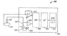
図6に、システム100に用いられる好適な計器が例示されている。図6の実施形態では、計器106は、LCDディスプレイ602、マイクロコントローラ(μC)604、AD変換器(A/D)606、増幅器608、電流電圧変換器610、バッテリー(VBAT)620、AC電流源622、及びスイッチ624を含む。計器106は、皮膚刺入部材102と電気接点104を電気的に接続するように適合されている。スイッチ624が閉じると(すなわち、オン)、計器106が、皮膚刺入部材102と電気接点104との間のインピーダンスを測定するために、これらの間にAC電流波形を流す。皮膚刺入部材と電気接点の前後の電流(I)及び電圧(V)を測定することにより、オームの法則:Z=V/Iを用いてインピーダンス(Z)を求めることができる。所望に応じて、インピーダンスの値から抵抗またはキャパシタンスを決定することができる。 FIG. 6 illustrates a suitable instrument used in the
電流源の振幅が、使用者には検出できない値(例えば、10mA未満)であるが、雑音比に対して良好な信号を生成するのに十分な値(例えば、1mA以上)に制限するのが有利である。本発明の例示的な実施形態では、電流の周波数は10KHz〜1MHzの範囲であり、この周波数範囲の低周波数が使用者への不快感を防止し、この周波数範囲の高周波数が測定される浮遊容量を最小限にする。 The amplitude of the current source is a value that cannot be detected by the user (eg, less than 10 mA), but is limited to a value (eg, 1 mA or more) sufficient to generate a good signal with respect to the noise ratio. It is advantageous. In an exemplary embodiment of the invention, the frequency of the current is in the range of 10 KHz to 1 MHz, a low frequency in this frequency range prevents discomfort to the user, and a high frequency in this frequency range is measured. Minimize capacity.
従来から、測定AC電圧及び電流を用いたインピーダンスの測定には高速A/D変換器及び他の比較的高価な電気部品が必要である。しかしながら、本発明に従ったシステムは、言及することを以って内容の全てを本明細書の一部とする米国特許出願第10/020,169号(2001年12月12日出願)及び同第09/988,495号(2001年11月20日出願)に開示されている比較的安価な技術を用いてインピーダンスを測定することができる。 Traditionally, measurement of impedance using measured AC voltage and current requires high speed A / D converters and other relatively expensive electrical components. However, the system according to the present invention is based on US patent application Ser. No. 10 / 020,169 (filed Dec. 12, 2001), which is hereby incorporated by reference in its entirety. The impedance can be measured using a relatively inexpensive technique disclosed in 09 / 988,495 (filed on Nov. 20, 2001).
図1に、皮膚刺入部材102が皮膚組織Dに接触していない(すなわち、皮膚刺入部材が皮膚組織Dの皮膚層に接触していない)時の皮膚刺入部材102、皮膚組織D、及び電気接点104の空間的関係が示されている。この空間的関係では、皮膚刺入部材と電気接点(皮膚組織Dの外側皮膚層に接触している)との間のインピーダンスは、通常は10MΩよりも大きい。しかしながら、計器に用いる電子部品の種類及びリーク電流の大きさによってインピーダンスの値は変化し得ることを理解されたい。 In FIG. 1, when
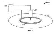
図7に、皮膚刺入部材102が電気接点104によって形成された円の中心点で皮膚組織Dに刺入しないで接触している時の皮膚刺入部材102、皮膚組織D、及び電気接点104の空間的関係が模式的に示されている。この空間的関係では、皮膚刺入部材102と電気接点104との間のインピーダンスは、通常は、例えば15kΩ〜約1MΩの範囲である。 In FIG. 7, the
図8に、皮膚刺入部材102が電気接点104によって形成された円の中心点で皮膚組織Dで刺入している時の皮膚刺入部材102、皮膚組織D、及び電気接点104の空間的関係が模式的に示されている。この空間的な関係では、皮膚刺入部材102と電気接点104の間のインピーダンスは通常、皮膚刺入部材が皮膚組織Dに刺入しないで接触している時のインピーダンスの10%以下と低い。制約するものではないが、インピーダンスのこのような大きな変化は、皮膚のインピーダンスの大部分が外側層すなわち表皮に存在することによるものであり、皮膚刺入部材が外側層を越えて皮膚組織に刺入するとインピーダンスが著しく低下するためであると推測される。 FIG. 8 shows a spatial view of the
上記した説明に基づき、使用中のシステムの皮膚刺入部材と電気接点との間のインピーダンスの測定で皮膚刺入及びこの刺入安定性が分かる。言い換えれば、システムの計器は、皮膚刺入部材と電気接点との間のインピーダンス(または抵抗)を測定することにより、刺入、刺入安定性、及び刺入期間(すなわち、サンプルの抽出及び移送に要した時間)を検出することができる。皮膚刺入部材が皮膚組織内に刺入すると、抵抗またはインピーダンスが著しく変化する。 Based on the above description, the skin penetration and the penetration stability can be determined by measuring the impedance between the skin penetration member and the electrical contact of the system in use. In other words, the instrument of the system measures the impedance (or resistance) between the skin penetration member and the electrical contact, thereby providing penetration, penetration stability, and penetration duration (ie, sample extraction and transfer). Time). When the skin penetration member is inserted into the skin tissue, the resistance or impedance changes significantly.
電気特性の測定における皮膚の抵抗の差による影響を少なくするために、複数の電気接点を利用することができる。この場合、電気接点間の電気特性の更なる測定を行って、電気接点と皮膚刺入部材との間の測定値を標準化することができる。様々な電気接点を用いることができるが、単純にするために、皮膚組織Dに刺入するための図9のシステム700は2つの電気接点を含むとして示されている。システム700は、皮膚刺入部材702、第1の電気接点704、第2の電気接点705、及び計器706を含む。計器706は、皮膚刺入部材702と第1及び第2の電気接点704、705との間に存在する電気特性(例えば、抵抗及び/またはインピーダンス)を測定するように構成されている。第1及び第2の電気接点を使用することにより、2つの電気接点間の異なる電気特性測定値が得られ、皮膚の種類及び状態に対する依存が少ない刺入の検出を行うことができる。 In order to reduce the influence of differences in skin resistance in measuring electrical properties, a plurality of electrical contacts can be used. In this case, further measurements of the electrical properties between the electrical contacts can be performed to standardize the measured values between the electrical contacts and the skin penetration member. Although various electrical contacts can be used, for simplicity, the
皮膚組織のインピーダンスは、高い気温や運動などによる周囲湿度や汗によって異なり得る。図9‐図11の実施形態では、モニタリングできる2つの追加のインピーダンス測定値は、皮膚刺入部材702と第1の電気接点704との間のインピーダンス測定値と、皮膚刺入部材702と第2の電気接点705との間のインピーダンス測定値である。これらのインピーダンス測定値を平均して、皮膚組織刺入の検出精度を高めることができる。加えて、皮膚刺入部材と第1の電気接点及び皮膚刺入部材と第2の電気接点の間の2つのインピーダンス測定値は、第1の電気接点及び第2の電気接点に均一な圧力が加えられたか否かについての判断基準となり得る。更に、均一な圧力が加えられたか否かの決定により、皮膚刺入部材が皮膚組織に垂直に刺入しない配置リスクを低減することができる。図9‐図11の実施形態は2つの電気接点を用いているが、当業者であれば、2つ以上の電気接点を用いて皮膚刺入部材が垂直に刺入されているかをより高精度に決定できることを理解できよう。 The impedance of skin tissue can vary depending on ambient humidity and sweat due to high temperatures and exercise. In the embodiment of FIGS. 9-11, two additional impedance measurements that can be monitored are the impedance measurement between the
更に、第1の電気接点と第2の電気接点との間のインピーダンスの測定結果を用いて、第1の電気接点と皮膚刺入部材との間のインピーダンスの測定値及び第2の電気接点と皮膚刺入部材との間のインピーダンスの測定値を標準化することができる。標準化されたインピーダンスRは、式:R=Rn/Rbから求めることができる。このRnは、第1の電気接点及び第2の電気接点の何れかと皮膚刺入部材との間のインピーダンス、または皮膚刺入部材と第1の電気接点の間のインピーダンスと皮膚刺入部材と第2の電気接点との間のインピーダンスの平均である。このRbは、第1の電気接点と第2の電気接点との間の測定インピーダンスである。Furthermore, using the measurement result of the impedance between the first electrical contact and the second electrical contact, the measured impedance value between the first electrical contact and the skin piercing member and the second electrical contact; The measured impedance value between the skin penetration member can be standardized. Standardized impedance R has the formula: can be obtained fromR = R n /R b. The Rn includes a first impedance between one of electrical contacts and a second electrical contact with the skin-piercing element or skin-piercing element and the impedance and the skin piercing element between the first electrical contact, It is the average of the impedance between the second electrical contact. This Rb is the measured impedance between the first electrical contact and the second electrical contact.
図9に、皮膚刺入部材704が皮膚組織Dに接触していない(すなわち、皮膚刺入部材が皮膚組織Dの皮膚層に接触していない)時の皮膚刺入部材702、皮膚組織D、及び第1及び第2の電気接点704、705の空間的関係が示されている。システム700では、第1及び第2の電気接点704、705が、図9‐図11に例示されているように距離L1によって分離され互いに絶縁されている。距離L1は、第1の電気接点704と第2の電気接点705との間の最小のギャップと定義され、通常は0.5mm〜2mmの範囲である。図9の空間的関係の場合、皮膚刺入部材702と第1の電気接点704との間のインピーダンス及び皮膚刺入部材702と第2の電気接点705との間のインピーダンスは、通常は10MΩよりも大きい。更に、第1の電気接点704と第2の電気接点705との間のインピーダンスは、通常は15kΩ〜約1MΩの範囲の有限値である。 FIG. 9 shows
図10に、皮膚刺入部材702が皮膚組織Dに刺入しないで接触している時の皮膚刺入部材702、皮膚組織D、及び第1及び第2の電気接点704の空間的関係が模式的に示されている。この空間的関係では、皮膚刺入部材702と第1の電気接点704との間のインピーダンス及び皮膚刺入部材702と第2の電気接点705との間のインピーダンスは通常、例えば、15kΩ〜約1MΩの範囲である。加えて、第1の電気接点704と第2の電気接点705との間のインピーダンスは通常、15kΩ〜約1MΩの範囲の有限値である。 FIG. 10 schematically shows the spatial relationship between the
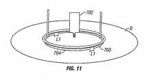
図11に、皮膚刺入部材702が皮膚組織Dに刺入している時の皮膚刺入部材702、皮膚組織D、及び第1及び第2の電気接点704、705の空間的関係が模式的に示されている。この空間的関係では、皮膚刺入部材102と第1の電気接点704または第2の電気接点705の一方との間のインピーダンスは通常、皮膚刺入部材が皮膚組織Dに刺入しないで接触している時のインピーダンスの10%以下と低い。更に、第1の電気接点704と第2の電気接点705との間のインピーダンスは、通常は15kΩ〜約1MΩの範囲の有限値である。 FIG. 11 schematically shows the spatial relationship between the
図12に、皮膚刺入部材702と第1の電気接点704または第2の電気接点705の一方との間の電気特性(すなわち、インピーダンス)の測定に好適な電子部品を含むシステム700に用いる好適な計器706が例示されている。図12に示されている計器706は、LCDディスプレイ722、マイクロコントローラ(μC)724、AD変換器(A/D)726、増幅器728、電流電圧変換器730、バッテリー(VBAT)732、AC電流源734、第1のスイッチ736、及び第2のスイッチ740を含む。計器706は、皮膚刺入部材702、第1の電気接点704、及び第2の電気接点705に機能的に接続されている。第1のスイッチ736が閉(すなわち、オン)、第2のスイッチ740が開(すなわち、オフ)の時、計器は、第2の電気接点705と第1の電気接点704との間のインピーダンスを測定するためにこれらの間にAC電流波形を流す。第1のスイッチ736が開、第2のスイッチ740が閉の時、皮膚刺入部材702と第1の電気接点704との間のインピーダンスを測定するためにこれらの間にAC電流波形を流す。第1のスイッチ736と第2のスイッチ740の両方が開の時、計器706は、例えば、グルコース値を測定して出力することができる。 FIG. 12 illustrates a
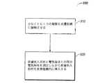
図13に、本発明の例示的な実施形態に従ったプロセス900の連続ステップを例示するフローチャートが示されている。プロセス900は、ステップ910に示されているように少なくとも1つの電極を皮膚組織に接触させるステップと、ステップ920に示されているように皮膚刺入部材を(例えば、一体型微小針/バイオセンサ)皮膚組織内に刺入するステップとを含む。挿入中に、皮膚刺入部材と電気接点との間に存在する電気特性(例えば、抵抗またはインピーダンス)を測定する。プロセス900の基礎をなす概念は、測定した電気特性の変化により、皮膚組織刺入の十分な深さ、及び/または十分なサンプルの抽出及び移送に要した時間(期間)、及び/または皮膚刺入部材の皮膚組織内での安定性を示すことができることである。 FIG. 13 shows a flowchart illustrating successive steps of a
所望に応じて、プロセス900は、皮膚刺入部材の皮膚組織刺入深さの表示(例えば、視覚的または聴覚的提示)、皮膚刺入部材の皮膚組織刺入安定性の表示、及び/または皮膚刺入部材の皮膚組織刺入期間(すなわち、サンプルの抽出及び移送に要した時間)の表示を使用者に提示するステップを含むこともできる。この表示は、測定した電気特性に基づくものである。 As desired,
ここに開示した本発明の実施形態の様々な代替形態を用いて本発明を実施できることを理解されたい。添付の特許請求の範囲が本発明の範囲を規定し、特許請求の範囲内の構造及び方法並びにそれらの等価物が本発明に含まれることを意図するものである。 It should be understood that the invention can be practiced with various alternatives to the embodiments of the invention disclosed herein. It is intended that the appended claims define the scope of the invention and that structures and methods within the scope of the claims and their equivalents be included in the present invention.
Claims (27)
Translated fromJapanese皮膚刺入部材と、
少なくとも1つの電気接点と、
前記システムの使用中に前記皮膚刺入部材と前記少なくとも1つの電気接点との間に存在する電気特性を測定するように構成された計器とを含むことを特徴とするシステム。A system for piercing skin tissue,
A skin penetration member;
At least one electrical contact;
And a meter configured to measure an electrical property that exists between the skin penetration member and the at least one electrical contact during use of the system.
皮膚刺入部材と、
第1の電気接点と、
第2の電気接点と、
前記システムの使用中に前記皮膚刺入部材と前記第1の電気接点及び前記第2の電気接点との間に存在する電気特性を測定するように構成された計器とを含むことを特徴とするシステム。A system for piercing skin tissue,
A skin penetration member;
A first electrical contact;
A second electrical contact;
An instrument configured to measure an electrical property existing between the skin penetration member and the first electrical contact and the second electrical contact during use of the system. system.
少なくとも1つの電気接点を皮膚組織に接触させるステップと、
前記皮膚刺入部材と前記少なくとも1つの電気接点との間に存在する電気特性を測定しながら皮膚刺入部材を皮膚組織に挿入して、前記皮膚組織に貫入するステップとを含むことを特徴とする方法。A method for piercing skin tissue,
Contacting at least one electrical contact with the skin tissue;
Inserting a skin piercing member into the skin tissue while measuring an electrical property existing between the skin piercing member and the at least one electrical contact, and penetrating the skin tissue. how to.
Applications Claiming Priority (2)
| Application Number | Priority Date | Filing Date | Title |
|---|---|---|---|
| US45240903P | 2003-03-06 | 2003-03-06 | |
| PCT/US2004/003142WO2004080306A1 (en) | 2003-03-06 | 2004-02-03 | System and method for piercing dermal tissue |
Publications (1)
| Publication Number | Publication Date |
|---|---|
| JP2006520251Atrue JP2006520251A (en) | 2006-09-07 |
Family
ID=32990654
Family Applications (1)
| Application Number | Title | Priority Date | Filing Date |
|---|---|---|---|
| JP2006508661APendingJP2006520251A (en) | 2003-03-06 | 2004-02-03 | System and method for piercing skin tissue |
Country Status (12)
| Country | Link |
|---|---|
| US (1) | US20060178573A1 (en) |
| EP (1) | EP1603458A1 (en) |
| JP (1) | JP2006520251A (en) |
| KR (1) | KR20050105100A (en) |
| CN (1) | CN100346746C (en) |
| AU (1) | AU2004220623A1 (en) |
| CA (1) | CA2482568A1 (en) |
| IL (1) | IL164521A0 (en) |
| MX (1) | MXPA04010963A (en) |
| NO (1) | NO20044799L (en) |
| RU (1) | RU2004132832A (en) |
| WO (1) | WO2004080306A1 (en) |
Cited By (3)
| Publication number | Priority date | Publication date | Assignee | Title |
|---|---|---|---|---|
| JP2008093146A (en)* | 2006-10-11 | 2008-04-24 | Matsushita Electric Ind Co Ltd | Blood test equipment |
| JP2010536469A (en)* | 2007-08-24 | 2010-12-02 | エイジェンシー フォー サイエンス, テクノロジー アンド リサーチ | Skin penetration detection system and method |
| JP2015154941A (en)* | 2008-10-29 | 2015-08-27 | エフ.ホフマン−ラ ロシュ アーゲーF. Hoffmann−La Roche Aktiengesellschaft | Apparatus and system for preparing a body fluid sample and analyzing it |
Families Citing this family (94)
| Publication number | Priority date | Publication date | Assignee | Title |
|---|---|---|---|---|
| US6036924A (en) | 1997-12-04 | 2000-03-14 | Hewlett-Packard Company | Cassette of lancet cartridges for sampling blood |
| US6391005B1 (en) | 1998-03-30 | 2002-05-21 | Agilent Technologies, Inc. | Apparatus and method for penetration with shaft having a sensor for sensing penetration depth |
| US6663602B2 (en) | 2000-06-16 | 2003-12-16 | Novo Nordisk A/S | Injection device |
| DE10057832C1 (en) | 2000-11-21 | 2002-02-21 | Hartmann Paul Ag | Blood analysis device has syringe mounted in casing, annular mounting carrying needles mounted behind test strip and being swiveled so that needle can be pushed through strip and aperture in casing to take blood sample |
| US8641644B2 (en) | 2000-11-21 | 2014-02-04 | Sanofi-Aventis Deutschland Gmbh | Blood testing apparatus having a rotatable cartridge with multiple lancing elements and testing means |
| US7041068B2 (en) | 2001-06-12 | 2006-05-09 | Pelikan Technologies, Inc. | Sampling module device and method |
| JP4272051B2 (en) | 2001-06-12 | 2009-06-03 | ペリカン テクノロジーズ インコーポレイテッド | Blood sampling apparatus and method |
| US7344507B2 (en) | 2002-04-19 | 2008-03-18 | Pelikan Technologies, Inc. | Method and apparatus for lancet actuation |
| WO2002101359A2 (en) | 2001-06-12 | 2002-12-19 | Pelikan Technologies, Inc. | Integrated blood sampling analysis system with multi-use sampling module |
| US9795747B2 (en) | 2010-06-02 | 2017-10-24 | Sanofi-Aventis Deutschland Gmbh | Methods and apparatus for lancet actuation |
| US9226699B2 (en) | 2002-04-19 | 2016-01-05 | Sanofi-Aventis Deutschland Gmbh | Body fluid sampling module with a continuous compression tissue interface surface |
| US7981056B2 (en) | 2002-04-19 | 2011-07-19 | Pelikan Technologies, Inc. | Methods and apparatus for lancet actuation |
| US8337419B2 (en) | 2002-04-19 | 2012-12-25 | Sanofi-Aventis Deutschland Gmbh | Tissue penetration device |
| EP1395185B1 (en) | 2001-06-12 | 2010-10-27 | Pelikan Technologies Inc. | Electric lancet actuator |
| JP4209767B2 (en) | 2001-06-12 | 2009-01-14 | ペリカン テクノロジーズ インコーポレイテッド | Self-optimized cutting instrument with adaptive means for temporary changes in skin properties |
| AU2002344825A1 (en) | 2001-06-12 | 2002-12-23 | Pelikan Technologies, Inc. | Method and apparatus for improving success rate of blood yield from a fingerstick |
| US7749174B2 (en) | 2001-06-12 | 2010-07-06 | Pelikan Technologies, Inc. | Method and apparatus for lancet launching device intergrated onto a blood-sampling cartridge |
| US9427532B2 (en) | 2001-06-12 | 2016-08-30 | Sanofi-Aventis Deutschland Gmbh | Tissue penetration device |
| US7344894B2 (en) | 2001-10-16 | 2008-03-18 | Agilent Technologies, Inc. | Thermal regulation of fluidic samples within a diagnostic cartridge |
| US7582099B2 (en) | 2002-04-19 | 2009-09-01 | Pelikan Technologies, Inc | Method and apparatus for penetrating tissue |
| US7291117B2 (en) | 2002-04-19 | 2007-11-06 | Pelikan Technologies, Inc. | Method and apparatus for penetrating tissue |
| US7141058B2 (en) | 2002-04-19 | 2006-11-28 | Pelikan Technologies, Inc. | Method and apparatus for a body fluid sampling device using illumination |
| US7674232B2 (en) | 2002-04-19 | 2010-03-09 | Pelikan Technologies, Inc. | Method and apparatus for penetrating tissue |
| US7892183B2 (en) | 2002-04-19 | 2011-02-22 | Pelikan Technologies, Inc. | Method and apparatus for body fluid sampling and analyte sensing |
| US7524293B2 (en) | 2002-04-19 | 2009-04-28 | Pelikan Technologies, Inc. | Method and apparatus for penetrating tissue |
| US7563232B2 (en) | 2002-04-19 | 2009-07-21 | Pelikan Technologies, Inc. | Method and apparatus for penetrating tissue |
| US7547287B2 (en) | 2002-04-19 | 2009-06-16 | Pelikan Technologies, Inc. | Method and apparatus for penetrating tissue |
| US8267870B2 (en) | 2002-04-19 | 2012-09-18 | Sanofi-Aventis Deutschland Gmbh | Method and apparatus for body fluid sampling with hybrid actuation |
| US9248267B2 (en) | 2002-04-19 | 2016-02-02 | Sanofi-Aventis Deustchland Gmbh | Tissue penetration device |
| US7374544B2 (en) | 2002-04-19 | 2008-05-20 | Pelikan Technologies, Inc. | Method and apparatus for penetrating tissue |
| US9314194B2 (en) | 2002-04-19 | 2016-04-19 | Sanofi-Aventis Deutschland Gmbh | Tissue penetration device |
| US8579831B2 (en) | 2002-04-19 | 2013-11-12 | Sanofi-Aventis Deutschland Gmbh | Method and apparatus for penetrating tissue |
| US8784335B2 (en) | 2002-04-19 | 2014-07-22 | Sanofi-Aventis Deutschland Gmbh | Body fluid sampling device with a capacitive sensor |
| US7481776B2 (en) | 2002-04-19 | 2009-01-27 | Pelikan Technologies, Inc. | Method and apparatus for penetrating tissue |
| US7976476B2 (en) | 2002-04-19 | 2011-07-12 | Pelikan Technologies, Inc. | Device and method for variable speed lancet |
| US9795334B2 (en) | 2002-04-19 | 2017-10-24 | Sanofi-Aventis Deutschland Gmbh | Method and apparatus for penetrating tissue |
| US7491178B2 (en) | 2002-04-19 | 2009-02-17 | Pelikan Technologies, Inc. | Method and apparatus for penetrating tissue |
| US7648468B2 (en) | 2002-04-19 | 2010-01-19 | Pelikon Technologies, Inc. | Method and apparatus for penetrating tissue |
| US7901362B2 (en) | 2002-04-19 | 2011-03-08 | Pelikan Technologies, Inc. | Method and apparatus for penetrating tissue |
| US7232451B2 (en) | 2002-04-19 | 2007-06-19 | Pelikan Technologies, Inc. | Method and apparatus for penetrating tissue |
| US7410468B2 (en) | 2002-04-19 | 2008-08-12 | Pelikan Technologies, Inc. | Method and apparatus for penetrating tissue |
| US7229458B2 (en) | 2002-04-19 | 2007-06-12 | Pelikan Technologies, Inc. | Method and apparatus for penetrating tissue |
| US7297122B2 (en) | 2002-04-19 | 2007-11-20 | Pelikan Technologies, Inc. | Method and apparatus for penetrating tissue |
| US8221334B2 (en) | 2002-04-19 | 2012-07-17 | Sanofi-Aventis Deutschland Gmbh | Method and apparatus for penetrating tissue |
| US7717863B2 (en) | 2002-04-19 | 2010-05-18 | Pelikan Technologies, Inc. | Method and apparatus for penetrating tissue |
| US7708701B2 (en) | 2002-04-19 | 2010-05-04 | Pelikan Technologies, Inc. | Method and apparatus for a multi-use body fluid sampling device |
| US7909778B2 (en) | 2002-04-19 | 2011-03-22 | Pelikan Technologies, Inc. | Method and apparatus for penetrating tissue |
| US7331931B2 (en) | 2002-04-19 | 2008-02-19 | Pelikan Technologies, Inc. | Method and apparatus for penetrating tissue |
| US7371247B2 (en) | 2002-04-19 | 2008-05-13 | Pelikan Technologies, Inc | Method and apparatus for penetrating tissue |
| US8702624B2 (en) | 2006-09-29 | 2014-04-22 | Sanofi-Aventis Deutschland Gmbh | Analyte measurement device with a single shot actuator |
| US8574895B2 (en) | 2002-12-30 | 2013-11-05 | Sanofi-Aventis Deutschland Gmbh | Method and apparatus using optical techniques to measure analyte levels |
| US7850621B2 (en) | 2003-06-06 | 2010-12-14 | Pelikan Technologies, Inc. | Method and apparatus for body fluid sampling and analyte sensing |
| WO2006001797A1 (en) | 2004-06-14 | 2006-01-05 | Pelikan Technologies, Inc. | Low pain penetrating |
| EP1635700B1 (en) | 2003-06-13 | 2016-03-09 | Sanofi-Aventis Deutschland GmbH | Apparatus for a point of care device |
| US8282576B2 (en) | 2003-09-29 | 2012-10-09 | Sanofi-Aventis Deutschland Gmbh | Method and apparatus for an improved sample capture device |
| EP1680014A4 (en) | 2003-10-14 | 2009-01-21 | Pelikan Technologies Inc | METHOD AND DEVICE FOR A VARIABLE USER INTERFACE |
| US8147426B2 (en)* | 2003-12-31 | 2012-04-03 | Nipro Diagnostics, Inc. | Integrated diagnostic test system |
| US8668656B2 (en) | 2003-12-31 | 2014-03-11 | Sanofi-Aventis Deutschland Gmbh | Method and apparatus for improving fluidic flow and sample capture |
| US7822454B1 (en) | 2005-01-03 | 2010-10-26 | Pelikan Technologies, Inc. | Fluid sampling device with improved analyte detecting member configuration |
| WO2006011062A2 (en) | 2004-05-20 | 2006-02-02 | Albatros Technologies Gmbh & Co. Kg | Printable hydrogel for biosensors |
| WO2005120365A1 (en) | 2004-06-03 | 2005-12-22 | Pelikan Technologies, Inc. | Method and apparatus for a fluid sampling device |
| ATE444090T1 (en) | 2004-10-21 | 2009-10-15 | Novo Nordisk As | SELECTION MECHANISM FOR A ROTARY PIN |
| EP1830699A2 (en)* | 2004-12-22 | 2007-09-12 | Novo Nordisk A/S | Sensor system and method for detecting problems with mounting of skin mountable medical devices |
| US8652831B2 (en) | 2004-12-30 | 2014-02-18 | Sanofi-Aventis Deutschland Gmbh | Method and apparatus for analyte measurement test time |
| EP1709906A1 (en) | 2005-04-07 | 2006-10-11 | F. Hoffmann-La Roche Ag | Method and device for blood sampling |
| US20090043264A1 (en) | 2005-04-24 | 2009-02-12 | Novo Nordisk A/S | Injection Device |
| EP1785090A1 (en)* | 2005-11-10 | 2007-05-16 | F.Hoffmann-La Roche Ag | Lancet device and system for skin detection |
| WO2007075091A2 (en)* | 2005-12-29 | 2007-07-05 | Rikshospitalet - Radiumhospitalet Hf | Method and apparatus for determining local tissue impedance for positioning of a needle |
| EP1815790A1 (en)* | 2006-02-04 | 2007-08-08 | Roche Diagnostics GmbH | Lancet device with impedance measuring unit |
| JP5062768B2 (en) | 2006-03-10 | 2012-10-31 | ノボ・ノルデイスク・エー/エス | INJECTION DEVICE AND METHOD FOR REPLACING CARTRIDGE OF THE DEVICE |
| CN101400394B (en) | 2006-03-10 | 2012-07-04 | 诺沃-诺迪斯克有限公司 | An injection device having a gearing arrangement |
| CN101405044B (en)* | 2006-03-20 | 2013-10-16 | 诺沃-诺迪斯克有限公司 | Determination of position of injection needle |
| ATE458517T1 (en) | 2006-05-16 | 2010-03-15 | Novo Nordisk As | TRANSMISSION MECHANISM FOR AN INJECTION DEVICE |
| JP5253387B2 (en) | 2006-05-18 | 2013-07-31 | ノボ・ノルデイスク・エー/エス | Injection device with mode locking means |
| US8052655B2 (en) | 2006-09-29 | 2011-11-08 | Novo Nordisk A/S | Injection device with electronic detecting means |
| US20080139903A1 (en)* | 2006-12-08 | 2008-06-12 | Isense Corporation | Method and apparatus for insertion of a sensor using an introducer |
| BRPI0809265A2 (en) | 2007-03-23 | 2014-10-07 | Novo Nordisk As | INJECTION DEVICE INCLUDING A TIGHTENING NUT |
| US9108006B2 (en) | 2007-08-17 | 2015-08-18 | Novo Nordisk A/S | Medical device with value sensor |
| CA2707820A1 (en) | 2007-12-31 | 2009-07-09 | Novo Nordisk A/S | Electronically monitored injection device |
| US20090221893A1 (en)* | 2008-02-29 | 2009-09-03 | Path Scientific, Llc | Unitized Painfree Blood Glucose Measuring Device |
| EP2265324B1 (en) | 2008-04-11 | 2015-01-28 | Sanofi-Aventis Deutschland GmbH | Integrated analyte measurement system |
| CN101361696B (en)* | 2008-09-25 | 2010-12-08 | 东南大学 | Electronic informatics measuring method and measuring device for meridian of human body |
| US9375169B2 (en) | 2009-01-30 | 2016-06-28 | Sanofi-Aventis Deutschland Gmbh | Cam drive for managing disposable penetrating member actions with a single motor and motor and control system |
| US9034172B2 (en) | 2009-09-08 | 2015-05-19 | Bayer Healthcare Llc | Electrochemical test sensor |
| US20120238841A1 (en)* | 2010-04-15 | 2012-09-20 | Mark Castle | Sample capture in one step for test strips |
| US8965476B2 (en) | 2010-04-16 | 2015-02-24 | Sanofi-Aventis Deutschland Gmbh | Tissue penetration device |
| CN102138864B (en)* | 2011-03-21 | 2013-09-18 | 东南大学 | Monitoring and evaluating method and monitoring and evaluating device of acupuncture treatment effect |
| JP6069351B2 (en) | 2011-12-29 | 2017-02-01 | ノボ・ノルデイスク・エー/エス | Torsion spring type automatic syringe with dial-up / dial-down administration mechanism |
| CN106470717B (en)* | 2014-06-03 | 2020-09-11 | 安姆根有限公司 | Drug delivery system and method of use |
| CN105054975A (en)* | 2015-07-31 | 2015-11-18 | 徐州医学院 | Device capable of improving puncturing precision of chest and abdomen |
| US20170188913A1 (en)* | 2015-12-30 | 2017-07-06 | Path Scientific, Llc | Method for Extracting Fluids from Tissue and Uses Thereof |
| US20170188925A1 (en)* | 2015-12-30 | 2017-07-06 | Path Scientific, Llc | Device and method for extracting fluids from tissue |
| US11623040B2 (en)* | 2019-07-03 | 2023-04-11 | Becton, Dickinson And Company | Sensing catheters |
| FR3138295B1 (en)* | 2022-07-28 | 2025-04-04 | Pkvitality | Method for monitoring a microneedle biochemical sensor |
Citations (5)
| Publication number | Priority date | Publication date | Assignee | Title |
|---|---|---|---|---|
| JPH02189129A (en)* | 1989-01-17 | 1990-07-25 | Furuno Electric Co Ltd | Bioimpedance measuring device |
| JPH03272737A (en)* | 1990-03-20 | 1991-12-04 | Olympus Optical Co Ltd | Tissue judging electrode |
| US5271413A (en)* | 1992-07-22 | 1993-12-21 | Dalamagas Photios P | Method to sense the tissue for injection from a hypodermic needle |
| JPH11309124A (en)* | 1998-03-30 | 1999-11-09 | Hewlett Packard Co <Hp> | Device and method for penetration test using shaft equipped with sensor for detecting penetration depth |
| JP2003159331A (en)* | 2001-11-28 | 2003-06-03 | Fukuda Denshi Co Ltd | Injection needle and injection auxiliary device |
Family Cites Families (19)
| Publication number | Priority date | Publication date | Assignee | Title |
|---|---|---|---|---|
| US5069223A (en)* | 1990-02-14 | 1991-12-03 | Georgetown University | Method of evaluating tissue changes resulting from therapeutic hyperthermia |
| DE4212723C1 (en)* | 1992-04-16 | 1993-11-04 | Arta Plast Ab Tyresoe | LANCETTE DEVICE FOR POINTING THE SKIN |
| US5708247A (en)* | 1996-02-14 | 1998-01-13 | Selfcare, Inc. | Disposable glucose test strips, and methods and compositions for making same |
| US6241862B1 (en)* | 1996-02-14 | 2001-06-05 | Inverness Medical Technology, Inc. | Disposable test strips with integrated reagent/blood separation layer |
| US7133717B2 (en)* | 1999-08-25 | 2006-11-07 | Johnson & Johnson Consumer Companies, Inc. | Tissue electroperforation for enhanced drug delivery and diagnostic sampling |
| US6283982B1 (en)* | 1999-10-19 | 2001-09-04 | Facet Technologies, Inc. | Lancing device and method of sample collection |
| RU2269954C2 (en)* | 2000-06-09 | 2006-02-20 | Дайэбитиз Дайэгностикс, Инк. | Cap for lancet device for punching dermal tissue (versions), cap for lancet device for punching tip of finger, cap for lancet device for punching curvilinear dermal tissue and lancet device for punching dermal tissue |
| CA2429572A1 (en)* | 2000-11-24 | 2002-07-18 | Ckm Diagnostics, Inc. | Nerve stimulator output control needle with depth determination capability and method of use |
| WO2003088851A1 (en)* | 2001-06-12 | 2003-10-30 | Pelikan Technologies, Inc. | Tissue penetration device |
| CN2482967Y (en)* | 2001-07-13 | 2002-03-27 | 施国平 | Means for adjusting depth of blood-sampling needle |
| US20030028087A1 (en)* | 2001-08-01 | 2003-02-06 | Yuzhakov Vadim Vladimirovich | Devices for analyte concentration determination and methods of using the same |
| US20030028125A1 (en)* | 2001-08-06 | 2003-02-06 | Yuzhakov Vadim V. | Physiological sample collection devices and methods of using the same |
| US7429258B2 (en)* | 2001-10-26 | 2008-09-30 | Massachusetts Institute Of Technology | Microneedle transport device |
| US6872298B2 (en)* | 2001-11-20 | 2005-03-29 | Lifescan, Inc. | Determination of sample volume adequacy in biosensor devices |
| US6856125B2 (en)* | 2001-12-12 | 2005-02-15 | Lifescan, Inc. | Biosensor apparatus and method with sample type and volume detection |
| US7060192B2 (en)* | 2002-05-09 | 2006-06-13 | Lifescan, Inc. | Methods of fabricating physiological sample collection devices |
| US20030212344A1 (en)* | 2002-05-09 | 2003-11-13 | Vadim Yuzhakov | Physiological sample collection devices and methods of using the same |
| US20030143113A2 (en)* | 2002-05-09 | 2003-07-31 | Lifescan, Inc. | Physiological sample collection devices and methods of using the same |
| US6922586B2 (en)* | 2002-05-20 | 2005-07-26 | Richard J. Davies | Method and system for detecting electrophysiological changes in pre-cancerous and cancerous tissue |
- 2004
- 2004-02-03KRKR1020047017793Apatent/KR20050105100A/ennot_activeWithdrawn
- 2004-02-03CACA002482568Apatent/CA2482568A1/ennot_activeAbandoned
- 2004-02-03AUAU2004220623Apatent/AU2004220623A1/ennot_activeAbandoned
- 2004-02-03CNCNB2004800003165Apatent/CN100346746C/ennot_activeExpired - Fee Related
- 2004-02-03JPJP2006508661Apatent/JP2006520251A/enactivePending
- 2004-02-03USUS10/511,495patent/US20060178573A1/ennot_activeAbandoned
- 2004-02-03MXMXPA04010963Apatent/MXPA04010963A/ennot_activeApplication Discontinuation
- 2004-02-03RURU2004132832/14Apatent/RU2004132832A/ennot_activeApplication Discontinuation
- 2004-02-03WOPCT/US2004/003142patent/WO2004080306A1/enactiveApplication Filing
- 2004-02-03EPEP04707817Apatent/EP1603458A1/ennot_activeWithdrawn
- 2004-10-12ILIL16452104Apatent/IL164521A0/enunknown
- 2004-11-04NONO20044799Apatent/NO20044799L/ennot_activeApplication Discontinuation
Patent Citations (5)
| Publication number | Priority date | Publication date | Assignee | Title |
|---|---|---|---|---|
| JPH02189129A (en)* | 1989-01-17 | 1990-07-25 | Furuno Electric Co Ltd | Bioimpedance measuring device |
| JPH03272737A (en)* | 1990-03-20 | 1991-12-04 | Olympus Optical Co Ltd | Tissue judging electrode |
| US5271413A (en)* | 1992-07-22 | 1993-12-21 | Dalamagas Photios P | Method to sense the tissue for injection from a hypodermic needle |
| JPH11309124A (en)* | 1998-03-30 | 1999-11-09 | Hewlett Packard Co <Hp> | Device and method for penetration test using shaft equipped with sensor for detecting penetration depth |
| JP2003159331A (en)* | 2001-11-28 | 2003-06-03 | Fukuda Denshi Co Ltd | Injection needle and injection auxiliary device |
Cited By (4)
| Publication number | Priority date | Publication date | Assignee | Title |
|---|---|---|---|---|
| JP2008093146A (en)* | 2006-10-11 | 2008-04-24 | Matsushita Electric Ind Co Ltd | Blood test equipment |
| JP2010536469A (en)* | 2007-08-24 | 2010-12-02 | エイジェンシー フォー サイエンス, テクノロジー アンド リサーチ | Skin penetration detection system and method |
| US8583225B2 (en) | 2007-08-24 | 2013-11-12 | Agency For Science, Technology And Research | System and method for detecting skin penetration |
| JP2015154941A (en)* | 2008-10-29 | 2015-08-27 | エフ.ホフマン−ラ ロシュ アーゲーF. Hoffmann−La Roche Aktiengesellschaft | Apparatus and system for preparing a body fluid sample and analyzing it |
Also Published As
| Publication number | Publication date |
|---|---|
| CN1697628A (en) | 2005-11-16 |
| IL164521A0 (en) | 2005-12-18 |
| RU2004132832A (en) | 2005-08-27 |
| MXPA04010963A (en) | 2005-06-08 |
| US20060178573A1 (en) | 2006-08-10 |
| KR20050105100A (en) | 2005-11-03 |
| NO20044799L (en) | 2004-12-08 |
| AU2004220623A1 (en) | 2004-09-23 |
| CA2482568A1 (en) | 2004-09-23 |
| WO2004080306A1 (en) | 2004-09-23 |
| EP1603458A1 (en) | 2005-12-14 |
| CN100346746C (en) | 2007-11-07 |
Similar Documents
| Publication | Publication Date | Title |
|---|---|---|
| JP2006520251A (en) | System and method for piercing skin tissue | |
| US6960287B2 (en) | Underfill detection system for a test sensor | |
| RU2290062C2 (en) | Electrochemical element, device, system and method for taking biological fluid sample and analyzing substance under study available in it | |
| US8038859B2 (en) | Electrochemical sensor and method for analyzing liquid sample | |
| US20220361777A1 (en) | Transdermal microneedle array patch | |
| US6561989B2 (en) | Thin lance and test sensor having same | |
| US20020006355A1 (en) | Hollow microneedle patch | |
| US20080081976A1 (en) | Method and device for sampling and analyzing interstitial fluid and whole blood samples | |
| US20100130883A1 (en) | In-Vivo Non-Invasive Bioelectric Impedance Analysis of Glucose-Mediated Changes in Tissue | |
| EP2873969B1 (en) | Hematocrit measurement system and measurement method using the same | |
| KR20020094899A (en) | Percutaneous biological fluid sampling and analyte measurement devices and methods | |
| CA2423077A1 (en) | Micro-invasive method for painless detection of analytes in extracellular space | |
| JP2003033336A (en) | Device and method for sampling and measuring biofluid component | |
| JP2020527973A (en) | A suction device, a device for sampling body fluids, and a method for detecting body fluid components. | |
| JP2010536469A (en) | Skin penetration detection system and method | |
| CN103002804A (en) | transdermal device | |
| TWI666034B (en) | Transdermal microneedle array patch | |
| WO2014125420A1 (en) | System and method for measuring an analyte in a sample and calculating hematocrit-insensitive glucose concentrations | |
| JP7371219B2 (en) | Determination of contamination of biosensors used in analyte measurement systems | |
| KR100541266B1 (en) | Composition of electrode for transdermal glucose measurement | |
| JP6404926B2 (en) | Method and system for determining erroneous measurement signals during a test measurement sequence | |
| JP2004033374A (en) | In vivo information detection unit | |
| WO2015091808A1 (en) | Hand-held test meter multi-event control solution measurement reminder |
Legal Events
| Date | Code | Title | Description |
|---|---|---|---|
| A621 | Written request for application examination | Free format text:JAPANESE INTERMEDIATE CODE: A621 Effective date:20070129 | |
| RD04 | Notification of resignation of power of attorney | Free format text:JAPANESE INTERMEDIATE CODE: A7424 Effective date:20071203 | |
| RD04 | Notification of resignation of power of attorney | Free format text:JAPANESE INTERMEDIATE CODE: A7424 Effective date:20080912 | |
| A131 | Notification of reasons for refusal | Free format text:JAPANESE INTERMEDIATE CODE: A131 Effective date:20091117 | |
| A02 | Decision of refusal | Free format text:JAPANESE INTERMEDIATE CODE: A02 Effective date:20100420 |