JP2006520240A - Mitral valve repair system and method for use - Google Patents
Mitral valve repair system and method for useDownload PDFInfo
- Publication number
- JP2006520240A JP2006520240AJP2006507062AJP2006507062AJP2006520240AJP 2006520240 AJP2006520240 AJP 2006520240AJP 2006507062 AJP2006507062 AJP 2006507062AJP 2006507062 AJP2006507062 AJP 2006507062AJP 2006520240 AJP2006520240 AJP 2006520240A
- Authority
- JP
- Japan
- Prior art keywords
- needle
- catheter
- suture
- lumen
- fastener
- Prior art date
- Legal status (The legal status is an assumption and is not a legal conclusion. Google has not performed a legal analysis and makes no representation as to the accuracy of the status listed.)
- Granted
Links
- 238000000034methodMethods0.000titleclaimsdescription38
- 210000004115mitral valveAnatomy0.000titleabstractdescription49
- 230000008439repair processEffects0.000titleabstractdescription21
- 210000002216heartAnatomy0.000claimsdescription41
- 239000003356suture materialSubstances0.000claimsdescription36
- 238000004891communicationMethods0.000claimsdescription30
- 210000003709heart valveAnatomy0.000claimsdescription23
- 239000012530fluidSubstances0.000claimsdescription15
- 230000000087stabilizing effectEffects0.000claimsdescription11
- 239000000463materialSubstances0.000claimsdescription9
- 230000037361pathwayEffects0.000claimsdescription3
- 229910001285shape-memory alloyInorganic materials0.000claimsdescription2
- 230000001225therapeutic effectEffects0.000claims1
- 210000001519tissueAnatomy0.000description41
- 210000005240left ventricleAnatomy0.000description10
- 210000005246left atriumAnatomy0.000description9
- 239000008280bloodSubstances0.000description7
- 210000004369bloodAnatomy0.000description7
- 238000001727in vivoMethods0.000description5
- 210000005245right atriumAnatomy0.000description5
- 230000002861ventricularEffects0.000description5
- 210000001765aortic valveAnatomy0.000description4
- 238000010009beatingMethods0.000description4
- 210000005241right ventricleAnatomy0.000description4
- 230000006641stabilisationEffects0.000description4
- 238000011105stabilizationMethods0.000description4
- 206010027727Mitral valve incompetenceDiseases0.000description3
- 239000000853adhesiveSubstances0.000description3
- 230000001070adhesive effectEffects0.000description3
- 210000003157atrial septumAnatomy0.000description3
- 230000004064dysfunctionEffects0.000description3
- 230000008569processEffects0.000description3
- 210000003102pulmonary valveAnatomy0.000description3
- 230000002829reductive effectEffects0.000description3
- 210000000591tricuspid valveAnatomy0.000description3
- 208000008883Patent Foramen OvaleDiseases0.000description2
- 208000001910Ventricular Heart Septal DefectsDiseases0.000description2
- 229940127219anticoagulant drugDrugs0.000description2
- 230000008602contractionEffects0.000description2
- 230000006866deteriorationEffects0.000description2
- 239000011521glassSubstances0.000description2
- 210000002837heart atriumAnatomy0.000description2
- 238000012977invasive surgical procedureMethods0.000description2
- 239000004033plasticSubstances0.000description2
- 229920003023plasticPolymers0.000description2
- 238000007634remodelingMethods0.000description2
- 238000001356surgical procedureMethods0.000description2
- 230000017423tissue regenerationEffects0.000description2
- 208000019901Anxiety diseaseDiseases0.000description1
- 244000025254Cannabis sativaSpecies0.000description1
- 102000008186CollagenHuman genes0.000description1
- 108010035532CollagenProteins0.000description1
- 206010061996Heart valve stenosisDiseases0.000description1
- 208000031481Pathologic ConstrictionDiseases0.000description1
- RTAQQCXQSZGOHL-UHFFFAOYSA-NTitaniumChemical compound[Ti]RTAQQCXQSZGOHL-UHFFFAOYSA-N0.000description1
- 241000251539Vertebrata <Metazoa>Species0.000description1
- HZEWFHLRYVTOIW-UHFFFAOYSA-N[Ti].[Ni]Chemical compound[Ti].[Ni]HZEWFHLRYVTOIW-UHFFFAOYSA-N0.000description1
- 230000009471actionEffects0.000description1
- 229910045601alloyInorganic materials0.000description1
- 239000000956alloySubstances0.000description1
- 239000003146anticoagulant agentSubstances0.000description1
- 230000036506anxietyEffects0.000description1
- 210000000709aortaAnatomy0.000description1
- 238000013459approachMethods0.000description1
- 230000001746atrial effectEffects0.000description1
- 238000005452bendingMethods0.000description1
- 239000000919ceramicSubstances0.000description1
- 229920001436collagenPolymers0.000description1
- 239000002131composite materialSubstances0.000description1
- 230000008878couplingEffects0.000description1
- 238000010168coupling processMethods0.000description1
- 238000005859coupling reactionMethods0.000description1
- 230000007547defectEffects0.000description1
- 229920001971elastomerPolymers0.000description1
- 239000000806elastomerSubstances0.000description1
- 239000004744fabricSubstances0.000description1
- 210000001105femoral arteryAnatomy0.000description1
- 210000003191femoral veinAnatomy0.000description1
- 230000006870functionEffects0.000description1
- 208000019622heart diseaseDiseases0.000description1
- 208000025339heart septal defectDiseases0.000description1
- 238000002513implantationMethods0.000description1
- 238000011065in-situ storageMethods0.000description1
- 208000014674injuryDiseases0.000description1
- 238000003780insertionMethods0.000description1
- 230000037431insertionEffects0.000description1
- 210000004731jugular veinAnatomy0.000description1
- 230000000670limiting effectEffects0.000description1
- 230000007257malfunctionEffects0.000description1
- 230000013011matingEffects0.000description1
- 238000012986modificationMethods0.000description1
- 230000004048modificationEffects0.000description1
- 238000012544monitoring processMethods0.000description1
- 210000003205muscleAnatomy0.000description1
- 230000003387muscularEffects0.000description1
- 210000001087myotubuleAnatomy0.000description1
- 229910001000nickel titaniumInorganic materials0.000description1
- 210000000056organAnatomy0.000description1
- 210000003540papillary muscleAnatomy0.000description1
- 230000002093peripheral effectEffects0.000description1
- 229920001296polysiloxanePolymers0.000description1
- 230000001681protective effectEffects0.000description1
- 238000005086pumpingMethods0.000description1
- 238000011084recoveryMethods0.000description1
- 230000000284resting effectEffects0.000description1
- 230000000717retained effectEffects0.000description1
- 230000002441reversible effectEffects0.000description1
- 238000009958sewingMethods0.000description1
- 229910001220stainless steelInorganic materials0.000description1
- 239000010935stainless steelSubstances0.000description1
- 230000036262stenosisEffects0.000description1
- 208000037804stenosisDiseases0.000description1
- 238000007920subcutaneous administrationMethods0.000description1
- 208000024891symptomDiseases0.000description1
- 229920001169thermoplasticPolymers0.000description1
- 239000004416thermosoftening plasticSubstances0.000description1
- 229910052719titaniumInorganic materials0.000description1
- 239000010936titaniumSubstances0.000description1
- 230000008733traumaEffects0.000description1
- 210000005166vasculatureAnatomy0.000description1
- 238000012800visualizationMethods0.000description1
Images


Classifications
- A—HUMAN NECESSITIES
- A61—MEDICAL OR VETERINARY SCIENCE; HYGIENE
- A61B—DIAGNOSIS; SURGERY; IDENTIFICATION
- A61B17/00—Surgical instruments, devices or methods
- A61B17/04—Surgical instruments, devices or methods for suturing wounds; Holders or packages for needles or suture materials
- A61B17/0469—Suturing instruments for use in minimally invasive surgery, e.g. endoscopic surgery
- A—HUMAN NECESSITIES
- A61—MEDICAL OR VETERINARY SCIENCE; HYGIENE
- A61B—DIAGNOSIS; SURGERY; IDENTIFICATION
- A61B17/00—Surgical instruments, devices or methods
- A61B17/04—Surgical instruments, devices or methods for suturing wounds; Holders or packages for needles or suture materials
- A61B17/0467—Instruments for cutting sutures
- A—HUMAN NECESSITIES
- A61—MEDICAL OR VETERINARY SCIENCE; HYGIENE
- A61B—DIAGNOSIS; SURGERY; IDENTIFICATION
- A61B17/00—Surgical instruments, devices or methods
- A61B17/04—Surgical instruments, devices or methods for suturing wounds; Holders or packages for needles or suture materials
- A61B17/0482—Needle or suture guides
- A—HUMAN NECESSITIES
- A61—MEDICAL OR VETERINARY SCIENCE; HYGIENE
- A61B—DIAGNOSIS; SURGERY; IDENTIFICATION
- A61B17/00—Surgical instruments, devices or methods
- A61B17/04—Surgical instruments, devices or methods for suturing wounds; Holders or packages for needles or suture materials
- A61B17/0487—Suture clamps, clips or locks, e.g. for replacing suture knots; Instruments for applying or removing suture clamps, clips or locks
- A—HUMAN NECESSITIES
- A61—MEDICAL OR VETERINARY SCIENCE; HYGIENE
- A61B—DIAGNOSIS; SURGERY; IDENTIFICATION
- A61B17/00—Surgical instruments, devices or methods
- A61B17/00234—Surgical instruments, devices or methods for minimally invasive surgery
- A61B2017/00238—Type of minimally invasive operation
- A61B2017/00243—Type of minimally invasive operation cardiac
- A—HUMAN NECESSITIES
- A61—MEDICAL OR VETERINARY SCIENCE; HYGIENE
- A61B—DIAGNOSIS; SURGERY; IDENTIFICATION
- A61B17/00—Surgical instruments, devices or methods
- A61B2017/00367—Details of actuation of instruments, e.g. relations between pushing buttons, or the like, and activation of the tool, working tip, or the like
- A61B2017/00371—Multiple actuation, e.g. pushing of two buttons, or two working tips becoming operational
- A—HUMAN NECESSITIES
- A61—MEDICAL OR VETERINARY SCIENCE; HYGIENE
- A61B—DIAGNOSIS; SURGERY; IDENTIFICATION
- A61B17/00—Surgical instruments, devices or methods
- A61B2017/00743—Type of operation; Specification of treatment sites
- A61B2017/00778—Operations on blood vessels
- A61B2017/00783—Valvuloplasty
- A—HUMAN NECESSITIES
- A61—MEDICAL OR VETERINARY SCIENCE; HYGIENE
- A61B—DIAGNOSIS; SURGERY; IDENTIFICATION
- A61B17/00—Surgical instruments, devices or methods
- A61B17/04—Surgical instruments, devices or methods for suturing wounds; Holders or packages for needles or suture materials
- A61B17/0401—Suture anchors, buttons or pledgets, i.e. means for attaching sutures to bone, cartilage or soft tissue; Instruments for applying or removing suture anchors
- A61B2017/0445—Suture anchors, buttons or pledgets, i.e. means for attaching sutures to bone, cartilage or soft tissue; Instruments for applying or removing suture anchors cannulated, e.g. with a longitudinal through-hole for passage of an instrument
- A—HUMAN NECESSITIES
- A61—MEDICAL OR VETERINARY SCIENCE; HYGIENE
- A61B—DIAGNOSIS; SURGERY; IDENTIFICATION
- A61B17/00—Surgical instruments, devices or methods
- A61B17/04—Surgical instruments, devices or methods for suturing wounds; Holders or packages for needles or suture materials
- A61B17/0401—Suture anchors, buttons or pledgets, i.e. means for attaching sutures to bone, cartilage or soft tissue; Instruments for applying or removing suture anchors
- A61B2017/0446—Means for attaching and blocking the suture in the suture anchor
- A61B2017/0448—Additional elements on or within the anchor
- A61B2017/0451—Cams or wedges holding the suture by friction
- A—HUMAN NECESSITIES
- A61—MEDICAL OR VETERINARY SCIENCE; HYGIENE
- A61B—DIAGNOSIS; SURGERY; IDENTIFICATION
- A61B17/00—Surgical instruments, devices or methods
- A61B17/04—Surgical instruments, devices or methods for suturing wounds; Holders or packages for needles or suture materials
- A61B17/0401—Suture anchors, buttons or pledgets, i.e. means for attaching sutures to bone, cartilage or soft tissue; Instruments for applying or removing suture anchors
- A61B2017/0464—Suture anchors, buttons or pledgets, i.e. means for attaching sutures to bone, cartilage or soft tissue; Instruments for applying or removing suture anchors for soft tissue
- A—HUMAN NECESSITIES
- A61—MEDICAL OR VETERINARY SCIENCE; HYGIENE
- A61B—DIAGNOSIS; SURGERY; IDENTIFICATION
- A61B17/00—Surgical instruments, devices or methods
- A61B17/04—Surgical instruments, devices or methods for suturing wounds; Holders or packages for needles or suture materials
- A61B17/0469—Suturing instruments for use in minimally invasive surgery, e.g. endoscopic surgery
- A61B2017/0472—Multiple-needled, e.g. double-needled, instruments
- A—HUMAN NECESSITIES
- A61—MEDICAL OR VETERINARY SCIENCE; HYGIENE
- A61B—DIAGNOSIS; SURGERY; IDENTIFICATION
- A61B17/00—Surgical instruments, devices or methods
- A61B17/04—Surgical instruments, devices or methods for suturing wounds; Holders or packages for needles or suture materials
- A61B17/0487—Suture clamps, clips or locks, e.g. for replacing suture knots; Instruments for applying or removing suture clamps, clips or locks
- A61B2017/0488—Instruments for applying suture clamps, clips or locks
- A—HUMAN NECESSITIES
- A61—MEDICAL OR VETERINARY SCIENCE; HYGIENE
- A61B—DIAGNOSIS; SURGERY; IDENTIFICATION
- A61B17/00—Surgical instruments, devices or methods
- A61B17/22—Implements for squeezing-off ulcers or the like on inner organs of the body; Implements for scraping-out cavities of body organs, e.g. bones; for invasive removal or destruction of calculus using mechanical vibrations; for removing obstructions in blood vessels, not otherwise provided for
- A61B2017/22051—Implements for squeezing-off ulcers or the like on inner organs of the body; Implements for scraping-out cavities of body organs, e.g. bones; for invasive removal or destruction of calculus using mechanical vibrations; for removing obstructions in blood vessels, not otherwise provided for with an inflatable part, e.g. balloon, for positioning, blocking, or immobilisation
- A61B2017/22052—Implements for squeezing-off ulcers or the like on inner organs of the body; Implements for scraping-out cavities of body organs, e.g. bones; for invasive removal or destruction of calculus using mechanical vibrations; for removing obstructions in blood vessels, not otherwise provided for with an inflatable part, e.g. balloon, for positioning, blocking, or immobilisation eccentric
- A—HUMAN NECESSITIES
- A61—MEDICAL OR VETERINARY SCIENCE; HYGIENE
- A61B—DIAGNOSIS; SURGERY; IDENTIFICATION
- A61B17/00—Surgical instruments, devices or methods
- A61B17/22—Implements for squeezing-off ulcers or the like on inner organs of the body; Implements for scraping-out cavities of body organs, e.g. bones; for invasive removal or destruction of calculus using mechanical vibrations; for removing obstructions in blood vessels, not otherwise provided for
- A61B2017/22051—Implements for squeezing-off ulcers or the like on inner organs of the body; Implements for scraping-out cavities of body organs, e.g. bones; for invasive removal or destruction of calculus using mechanical vibrations; for removing obstructions in blood vessels, not otherwise provided for with an inflatable part, e.g. balloon, for positioning, blocking, or immobilisation
- A61B2017/22065—Functions of balloons
- A61B2017/22069—Immobilising; Stabilising
- A—HUMAN NECESSITIES
- A61—MEDICAL OR VETERINARY SCIENCE; HYGIENE
- A61B—DIAGNOSIS; SURGERY; IDENTIFICATION
- A61B17/00—Surgical instruments, devices or methods
- A61B17/30—Surgical pincettes, i.e. surgical tweezers without pivotal connections
- A61B2017/306—Surgical pincettes, i.e. surgical tweezers without pivotal connections holding by means of suction
- A—HUMAN NECESSITIES
- A61—MEDICAL OR VETERINARY SCIENCE; HYGIENE
- A61F—FILTERS IMPLANTABLE INTO BLOOD VESSELS; PROSTHESES; DEVICES PROVIDING PATENCY TO, OR PREVENTING COLLAPSING OF, TUBULAR STRUCTURES OF THE BODY, e.g. STENTS; ORTHOPAEDIC, NURSING OR CONTRACEPTIVE DEVICES; FOMENTATION; TREATMENT OR PROTECTION OF EYES OR EARS; BANDAGES, DRESSINGS OR ABSORBENT PADS; FIRST-AID KITS
- A61F2/00—Filters implantable into blood vessels; Prostheses, i.e. artificial substitutes or replacements for parts of the body; Appliances for connecting them with the body; Devices providing patency to, or preventing collapsing of, tubular structures of the body, e.g. stents
- A61F2/02—Prostheses implantable into the body
- A61F2/24—Heart valves ; Vascular valves, e.g. venous valves; Heart implants, e.g. passive devices for improving the function of the native valve or the heart muscle; Transmyocardial revascularisation [TMR] devices; Valves implantable in the body
- A61F2/2442—Annuloplasty rings or inserts for correcting the valve shape; Implants for improving the function of a native heart valve
Landscapes
- Health & Medical Sciences (AREA)
- Life Sciences & Earth Sciences (AREA)
- Surgery (AREA)
- Heart & Thoracic Surgery (AREA)
- Engineering & Computer Science (AREA)
- Biomedical Technology (AREA)
- Nuclear Medicine, Radiotherapy & Molecular Imaging (AREA)
- Medical Informatics (AREA)
- Molecular Biology (AREA)
- Animal Behavior & Ethology (AREA)
- General Health & Medical Sciences (AREA)
- Public Health (AREA)
- Veterinary Medicine (AREA)
- Surgical Instruments (AREA)
- Prostheses (AREA)
Abstract
Translated fromJapaneseDescription
Translated fromJapanese (発明の背景)
脊椎動物において、心臓は、4つのポンプ輸送チャンバー:左心房、左心室、右心房および右心室を有する中空の筋肉器官である。心房は、個々の心房−心室接続部に位置する一方向弁によってそれらの個々の心室から隔離されている。これらの弁は、心臓の左側の僧帽弁(または二尖弁)、および心臓の右側の三尖弁として識別されている。左心室および右心室からの出口弁は、それぞれ、大動脈弁および肺動脈弁として識別されている。(Background of the Invention)
In vertebrates, the heart is a hollow muscular organ with four pumping chambers: left atrium, left ventricle, right atrium and right ventricle. The atria are isolated from their individual ventricles by a one-way valve located at the individual atrial-ventricular junction. These valves have been identified as the mitral valve (or bicuspid valve) on the left side of the heart and the tricuspid valve on the right side of the heart. Outlet valves from the left and right ventricles have been identified as aortic and pulmonary valves, respectively.
これらの心臓の弁は、心房および心室の筋肉繊維に直接または間接的いずれかで付着している密な線維輪を含む弁輪に配置されている。柔軟なコラーゲン構造を含む弁小葉は、輪に付着し、かつそれから内側に延び、接着エッジで交わっている。上記の大動脈弁、三尖弁および肺動脈弁の各々は3つの小葉を有し、その一方、僧帽弁だけは2つをもつ。通常の作動では、僧帽弁の小葉は、左心室が拡張するとき開き、それによって、血液が左心房から左心室に流れることを可能にする。小葉は、次いで、左心室の収縮サイクルの間に接触(すなわち、閉鎖)し、それによって血液が左心房に戻ることを防ぎ、そして血液を、大動脈弁を通って左心室から出るようにする。同様に、三尖弁は、右心房から右心室への流れを調節し、そして肺動脈弁は、右心室を出る血液を調節する。 These heart valves are placed in an annulus that includes a dense annulus that is attached either directly or indirectly to the atrial and ventricular muscle fibers. Valve leaflets containing a flexible collagen structure attach to the annulus and extend inward from it, intersecting at the adhesive edge. Each of the aortic, tricuspid and pulmonary valves described above has three leaflets, while only the mitral valve has two. In normal operation, the mitral leaflet opens when the left ventricle expands, thereby allowing blood to flow from the left atrium to the left ventricle. The leaflets then contact (ie, close) during the left ventricular contraction cycle, thereby preventing blood from returning to the left atrium and allowing blood to exit the left ventricle through the aortic valve. Similarly, the tricuspid valve regulates flow from the right atrium to the right ventricle, and the pulmonary valve regulates blood exiting the right ventricle.
多くの臨床的理由のために、心臓弁にともなう種々の問題が発生し得る。心臓疾患の1つの共通の形態は、狭窄および/または機能不全に至る心臓弁の悪化または劣化を含む。心臓弁狭窄は、弁が適正に開放しない症状である。機能不全は弁が適正に閉鎖しない症状である。左心室中の比較的高い流体圧のために最も一般的な僧帽弁の機能不全は、血液がその意図された進路を逆行し、そして心室収縮の間に左心室から左心房に「後方」に流れる症状である僧帽弁逆流(「MR」)を生じる。 For many clinical reasons, various problems with heart valves can occur. One common form of heart disease involves deterioration or deterioration of the heart valve leading to stenosis and / or dysfunction. Heart valve stenosis is a condition in which the valve does not open properly. Dysfunction is a condition in which the valve does not close properly. Due to the relatively high fluid pressure in the left ventricle, the most common mitral valve dysfunction is that the blood reverses its intended path and “backwards” from the left ventricle to the left atrium during ventricular contraction. Causes mitral regurgitation ("MR"), a symptom that flows into
劣化またはそうでなければ無能な心臓弁を修復するための多くの方法が開発されている。一般的な手順は、生来の大動脈弁または僧帽弁の補綴心臓弁での置換を含む。これらの手順は、外科医が患者の胸部(または可能であれば皮下)を通じて心臓までの接近を得ることが必要であり、無能な生来の心臓弁および関連する組織を外科的に除去し、周辺の弁輪を改造し、そして改造された輪内に置換弁を固定する。このような手順は、非常に有効であり得るが、このような置換弁に関連する欠点が存在する。例えば、この移植手順の侵襲的性質は、代表的には、患者のかなりの不安感を生じ、そして患者が、延長された回復期間の間入院したままであることを必要とする。さらに、2つの基礎的タイプの市販されている置換弁である、機械的弁および組織弁は、各々がそれら自身の決定を有している。機械的置換弁は、代表的には、延長された作動寿命を提供するが、患者は、通常、彼または彼女の寿命の残りについて抗凝固薬物の養生法を維持することが必要である。組織弁は、代表的には、抗凝固剤に対する必要性を減少またはなくす身体による高い程度の受け入れを提供する。しかし、組織弁の作動寿命は、代表的には、機械的弁より短く、そしてそれ故、患者の寿命の間に引き続く置換(単数または複数)を必要とし得る。 Many methods have been developed to repair degraded or otherwise incompetent heart valves. A common procedure involves the replacement of a native aortic or mitral valve with a prosthetic heart valve. These procedures require the surgeon to gain access to the heart through the patient's chest (or subcutaneous if possible), surgically removing the incompetent native heart valve and associated tissue, Remodel the annulus and secure the replacement valve in the remodeled ring. Although such a procedure can be very effective, there are drawbacks associated with such replacement valves. For example, the invasive nature of this implantation procedure typically results in considerable patient anxiety and requires that the patient remain hospitalized for an extended recovery period. In addition, two basic types of commercially available replacement valves, mechanical valves and tissue valves, each have their own decisions. Mechanical replacement valves typically provide an extended operating life, but the patient is usually required to maintain an anticoagulant medication regimen for the remainder of his or her life. Tissue valves typically provide a high degree of acceptance by the body that reduces or eliminates the need for anticoagulants. However, the working life of a tissue valve is typically shorter than a mechanical valve and may therefore require subsequent replacement (s) during the life of the patient.
補綴心臓弁置換に対する代替として、生来の心臓弁および/または周辺組織を改造することがしばしば好ましい。弁の改造は、しばしば、僧帽弁置換よりも良好に左心室機能を保存する。なぜなら、弁下乳頭筋肉および腱索が保存されるからである(大部分の補綴弁はこれら筋肉を利用しない)。弁の改造は、補綴リング(別名輪状形成術リング)を、弁輪中に移植することにより達成され得、弁の機能不全を矯正するために輪の構造を減少および/または安定化する。輪状形成術リングは、代表的には、織物の縫い材料で覆われた弾力性のコアから構築される。輪状形成術手順は単独で実施され得るか、またはそれらは、小葉修復のようなその他の手順と組み合わせて実施され得る。このような輪状形成術手順は、人気があり、そして良好に承認されているけれども、周辺輪の再形状化および伝統的な小葉修復は、常に、最適小葉接着に至るとは限らない。結果として、幾人かの患者は、このような輪状形成術手順の後、残存する僧帽弁逆流をなお経験し得る。 As an alternative to prosthetic heart valve replacement, it is often preferred to modify the native heart valve and / or surrounding tissue. Valve remodeling often preserves left ventricular function better than mitral valve replacement. This is because the sub papillary muscles and chordae are preserved (most prosthetic valves do not utilize these muscles). Valve remodeling can be accomplished by implanting a prosthetic ring (also known as an annuloplasty ring) into the annulus, reducing and / or stabilizing the annulus structure to correct valve malfunction. Annuloplasty rings are typically constructed from a resilient core covered with a fabric sewing material. Annuloplasty procedures can be performed alone or they can be performed in combination with other procedures such as leaflet repair. Although such annuloplasty procedures are popular and well-approved, peripheral ring reshaping and traditional leaflet repair do not always lead to optimal leaflet adhesion. As a result, some patients may still experience residual mitral regurgitation after such annuloplasty procedures.
「ボータイ(bow−tie)」修復として知られる最近開発された技法がまた、機能不全の心臓弁、特に僧帽弁を修復するために提唱されている。この僧帽弁ボータイ技法は、前方小葉および後方小葉を、それらの接着エッジの中央近傍で縫合、それによって、血液を2の新たに形成された開口部を通じて流すことを含む。これは、心房から心室に流れ得る血液の容量を減少するが、この損失は、僧帽弁逆流を減少する改良された生葉接着により補償される。当初は、Ottavio Alfieri博士によって開発されたこのプロセスは、心臓を静止させ、そして患者を体外バイパスに配置することを包含し、そして小葉に接近かつ一緒に-縫合するために侵襲的手術を要求した。しかし、より最近、ある人が、「拍動心臓」手順を提唱し、そこでは、心臓は、遠隔から接近され、そしてボータイ手順を通じ活性なままである。 A recently developed technique known as “bow-tie” repair has also been proposed to repair dysfunctional heart valves, particularly mitral valves. This mitral valve bowtie technique involves suturing the anterior and posterior leaflets near the center of their adhesive edges, thereby allowing blood to flow through the two newly formed openings. This reduces the volume of blood that can flow from the atria to the ventricles, but this loss is compensated by improved leaf adhesion that reduces mitral regurgitation. Originally developed by Dr. Ottabio Alfieri, this process involved resting the heart and placing the patient in an extracorporeal bypass and required invasive surgery to access and jointly-sew the leaflets . More recently, however, some have proposed a “beating heart” procedure in which the heart is accessed remotely and remains active throughout the bowtie procedure.
拍動心臓ボータイ手順(すなわち、体外バイパスなし)を実施するための1つの特定の方法か、Columbia大学のMehmet Oz博士によって提案された(1999年1月7日に公開され、その内容が本明細書中に参考として援用されるPCT公開WO 99/00059を参照のこと)。この手順の1つの実施形態では、関連するデバイスは、連結ステップの前に、接着位置に僧帽弁小葉を握りかつ保持するために用いられる鉗子様グラスパから成る。僧帽弁小葉は、それらの接合エッジで、左心室腔に向かって湾曲かつ僅かに入っているので、上記グラスパデバイスは、左心室の頂上でシールされたアパーチャを通過する。接合する僧帽弁小葉のエッジが、次いで、一緒に握られ、かつ保持され、そして引き続き、クリップまたは縫合糸のような締結デバイスがそれらを固定するために利用される。Mehmet Ozはまた、固定化の前に、僧帽弁小葉の整列を許容するように互いに対して直線的にスライド可能であるグラスパデバイス上の歯を開示している。この手順は、拍動心臓に対して行われるので、左心室および僧帽弁内の圧力およびモニターが厳格であり、そしてOz博士の手順を、非常に技能集約的にすることが容易に理解される。 One specific method for performing a beating heart bowtie procedure (ie, no extracorporeal bypass) was proposed by Dr. Mehmet Oz of the University of Columbia (published January 7, 1999, the contents of which are (See PCT Publication WO 99/00059, which is incorporated herein by reference). In one embodiment of this procedure, the associated device consists of a forceps-like glass blade that is used to grip and hold the mitral valve leaflet in an adhesive position prior to the coupling step. Because the mitral leaflets are curved and slightly into the left ventricular cavity at their mating edges, the Graspa device passes through a sealed aperture at the top of the left ventricle. The joining mitral leaflet edges are then grasped and held together and a fastening device such as a clip or suture is then utilized to secure them. Mehmet Oz also discloses teeth on the glass blade device that are slidable linearly relative to each other to allow alignment of the mitral leaflets before fixation. Since this procedure is performed on a beating heart, it is readily understood that pressure and monitoring in the left ventricle and mitral valve is rigorous and makes Dr. Oz's procedure very skill intensive. The
上記ボータイ手順は、そうでなければ、無能な心臓弁を処置するために実行可能な代替であることが証明されている。それにもかかわらず、現在のこのボータイ手順に関連する欠点が識別されている。現在のシステムは、代表的には、機械的グラスパを有する組織安定化デバイス、とげのある部材、および減圧デバイスを含む。しばしば、これらデバイスの使用は、より少ない最適小葉安定化およびファスナー配置を生じる。これら問題の多くは、外科医が、1つの比較的柔軟性のない手順で小葉を捕獲、保持および固定化することを要求されるという事実から生じる。これらの困難性は、これらの小葉が小さくまたは石灰化され、一緒に引っ張ることを困難にするとき、およびこれら小葉が活発に機能している拍動心臓手順において複雑になる。さらに、大部分の現在のデバイスのサイズおよび複雑さは、不可能ではないにしても、最小の侵襲外科的手順をより困難にする。 The bowtie procedure has proven to be a viable alternative to treat otherwise incompetent heart valves. Nevertheless, shortcomings associated with this current bowtie procedure have been identified. Current systems typically include a tissue stabilization device having a mechanical grass blade, a barbed member, and a vacuum device. Often, the use of these devices results in less optimal leaflet stabilization and fastener placement. Many of these problems stem from the fact that surgeons are required to capture, retain and immobilize leaflets in one relatively inflexible procedure. These difficulties are complicated when these leaflets are small or calcified making it difficult to pull together and in beating heart procedures where these leaflets are actively functioning. Moreover, the size and complexity of most current devices makes minimal invasive surgical procedures more difficult if not impossible.
前述を考慮して、複数の組織心臓弁小葉を安定化し、そしてそれらの間に固定化デバイスを配置するための改良されたシステムに対する必要性が現在存在している。より詳細には、患者の僧帽弁を修復するための改良されたボータイ手順に対する現在の必要性が存在している。 In view of the foregoing, a need currently exists for an improved system for stabilizing a plurality of tissue heart valve leaflets and placing an immobilization device therebetween. More particularly, there is a current need for an improved bowtie procedure for repairing a patient's mitral valve.
(発明の簡単な要旨)
本発明は、インビボで少なくとも1つの組織部分を効率的に安定化する問題を解決する。さらに、本発明は、遠隔の挿入位置がカテーテルを通じて安定化された組織にファスナーを送達し得るデバイスを提供する。(Simple Summary of Invention)
The present invention solves the problem of efficiently stabilizing at least one tissue portion in vivo. Furthermore, the present invention provides a device that can deliver a fastener to tissue where the remote insertion location is stabilized through the catheter.
1つの局面では、本発明は、患者の心臓内の組織を修復するためのシステムに関し、そして、近位端、遠位端、およびその中に形成された少なくとも1つの内部管腔を有するガイドカテーテル、この組織に少なくとも1つの縫合糸を付与し得る治療カテーテル、およびこの縫合糸に少なくとも1つのファスナーを取り付け得るファスナーカテーテルを含む。上記治療カテーテルおよびファスナーカテーテルは、上記ガイドカテーテルの内部管腔を横切り得る。 In one aspect, the present invention relates to a system for repairing tissue in a patient's heart and having a proximal end, a distal end, and at least one internal lumen formed therein. A treatment catheter capable of applying at least one suture to the tissue, and a fastener catheter capable of attaching at least one fastener to the suture. The treatment catheter and fastener catheter can traverse the inner lumen of the guide catheter.
別の局面では、本発明は、患者の心臓内の組織を修復するためのシステムに関し、そして、近位端、遠位端、およびその中に形成された少なくとも1つの内部管腔を有するガイドカテーテル、その中に配置された少なくとも1つのニードルポートと連通する少なくとも1つのニードル管腔を有し、このニードル管腔内に位置決めされた少なくとも1つのニードルを有する治療カテーテル、およびそれに離脱可能に連結された少なくとも1つのファスナーを有するファスナーカテーテルを備える。さらに、このファスナーカテーテルは、少なくとも1つの切断部材を含む。 In another aspect, the present invention relates to a system for repairing tissue in a patient's heart and having a proximal end, a distal end, and at least one internal lumen formed therein. A treatment catheter having at least one needle lumen in communication with at least one needle port disposed therein and having at least one needle positioned within the needle lumen, and removably coupled thereto And a fastener catheter having at least one fastener. The fastener catheter further includes at least one cutting member.
なお別の局面では、本発明は、患者の心臓内の組織を修復するためのシステムを開示し、そしてこの患者中に挿入され、そして循環経路を通じて進行され得るガイドワイア、このガイドワイアに取り付け可能であり、そして上記組織に少なくとも1つの縫合糸を付与し得る治療カテーテル、および上記ガイドワイアに取り付け可能であり、そして上記縫合糸に少なくとも1つのファスナーを取り付け得るファスナーカテーテルを含む。 In yet another aspect, the present invention discloses a system for repairing tissue in a patient's heart and a guide wire that can be inserted into the patient and advanced through the circulatory pathway, attachable to the guide wire And a treatment catheter capable of applying at least one suture to the tissue, and a fastener catheter attachable to the guide wire and capable of attaching at least one fastener to the suture.
さらなる局面では、本発明は、患者の心臓内に位置する組織に組織修復デバイスを送達するためのガイドカテーテルに関し、そして外部壁管腔を規定する外側壁、その中に操縦デバイスを受容し得る方向付け管腔、およびこの外側壁内に配置される柔軟な支持デバイスを備える。 In a further aspect, the present invention relates to a guide catheter for delivering a tissue repair device to tissue located within a patient's heart, and an outer wall defining an outer wall lumen, the direction in which a steering device can be received. A mounting lumen and a flexible support device disposed within the outer wall.
別の局面では、本発明は、患者の心臓内の組織に縫合糸を送達するためのカテーテルを開示し、そして、遠位端、この遠位端の上に形成された少なくとも1つの吸引凹部、この吸引凹部に近接して位置する少なくとも1つのニードルポート、このニードルポートと連通し、その中に配置された少なくとも1つのニードルを有する少なくとも1のニードル管腔、この吸引凹部に近接して配置され、その中に位置する少なくとも1つのニードルクラッチを有する少なくとも1つのニードル受容ポート、およびこのニードルと連通している少なくとも1つのアクチェエータ部材を有する細長い本体を含む。 In another aspect, the present invention discloses a catheter for delivering a suture to tissue in a patient's heart, and a distal end, at least one suction recess formed on the distal end, At least one needle port located proximate to the suction recess, at least one needle lumen in communication with the needle port and having at least one needle disposed therein, disposed proximate to the suction recess , At least one needle receiving port having at least one needle clutch positioned therein, and an elongated body having at least one actuator member in communication with the needle.
なお別の局面では、本発明は、患者の心臓内の組織に、縫合糸を送達するためのカテーテルに関し、そしてその上に形成された少なくとも1つの吸引凹部をもつ遠位端、該吸引凹部に近接して位置する少なくとも1つのニードルポート、その中に配置された縫合糸材料に取り付けられた少なくとも1つの離脱可能なニードルを有し、かつ上記ニードルポートと連通する少なくとも1つのニードル管腔、該吸引凹部に近接して位置する少なくとも1つのニードル受容ポート、このニードル受容ポート内に配置された離脱可能なニードルを受容し得る少なくとも1つのニードルトラップ、およびこのニードルと連通する少なくとも1つのアクチュエータ部材を有する細長い本体を備える。 In yet another aspect, the present invention relates to a catheter for delivering a suture to tissue in a patient's heart, and a distal end having at least one suction recess formed thereon, the suction recess At least one needle port located proximately, having at least one releasable needle attached to a suture material disposed therein and at least one needle lumen communicating with said needle port; At least one needle receiving port located proximate to the suction recess, at least one needle trap capable of receiving a removable needle disposed in the needle receiving port, and at least one actuator member in communication with the needle Having an elongated body.
なお別の局面では、本発明は、患者の身体内の組織に付着された縫合糸材料にファスナーを付与するためのデバイスに関し、そして近位端および遠位端、縫合糸凹部および作動凹部を規定する内部本体を有するカテーテル本体、および配備管腔を規定する移動可能なスリーブを含む。上記内部本体上の縫合糸凹部は、その中にファスナーを受容し得るファスナー管腔と連通している。上記作動凹部は、上記内部本体中に形成された作動管腔と連通している。上記移動可能なスリーブ中に形成された配備管腔は、その中に上記内部本体を受容するようなサイズであり、そしてそれに近接して位置する切断部材を有する切断凹部を含む。 In yet another aspect, the present invention relates to a device for attaching a fastener to a suture material attached to tissue within a patient's body and defining a proximal and distal end, a suture recess and an actuation recess. A catheter body having an inner body and a movable sleeve defining a deployment lumen. The suture recess on the inner body communicates with a fastener lumen that can receive a fastener therein. The operating recess communicates with an operating lumen formed in the inner body. A deployment lumen formed in the movable sleeve is sized to receive the inner body therein and includes a cutting recess having a cutting member positioned proximate thereto.
別の局面では、本発明は、縫合材料に取り付け得るファスナーに関し、そしてその中に形成された少なくとも1つの取り付け管腔を有するファスナー本体、およびこのファスナー本体に取り付けられた少なくとも1つの係合部材を備え、ここで、この係合部材は、上記縫合糸材料を係合および保持し得る。この係合部材は、上記取り付け管腔と連通している係合アパーチャを規定する。この取り付け管腔は、その中に少なくとも1つの縫合糸を受容し得る。 In another aspect, the invention relates to a fastener that can be attached to a suture material, and a fastener body having at least one attachment lumen formed therein, and at least one engagement member attached to the fastener body. Wherein the engagement member may engage and retain the suture material. The engagement member defines an engagement aperture that communicates with the attachment lumen. The attachment lumen can receive at least one suture therein.
本発明はまた、患者の身体内の心臓弁組織を修復する種々の方法を開示する。1つの局面では、患者の心臓内の組織を修復する方法が開示され、この方法は、ガイドカテーテルを、循環経路を通じて心臓弁に近接する心臓内の位置に進行する工程、このガイドカテーテルを通じて上記心臓弁に治療カテーテルを進行する工程、上記治療カテーテルで第1の小葉を安定化する工程、第1の縫合糸材料を、この安定化された第1の小葉中に配備する工程、この第1の小葉を、上記治療カテーテルから、この第1の縫合糸材料をそれに取り付けたままにしながら解放する工程、第2の小葉を上記治療カテーテルで安定化する工程、第2の縫合糸材料を、上記第2の小葉中に配備する工程、この第2の小葉を、上記治療カテーテルから、この第2の縫合糸材料をそれに取り付けたままにしながら解放する工程、および、この第1の縫合糸と第2の縫合糸との間の距離を減少することにより、この第1の小葉および第2の小葉を接続する工程を包含する。 The present invention also discloses various methods of repairing heart valve tissue within a patient's body. In one aspect, a method of repairing tissue in a patient's heart is disclosed, the method comprising advancing a guide catheter to a location in the heart proximate to a heart valve through a circulatory pathway, the heart through the guide catheter. Advancing a treatment catheter to the valve, stabilizing the first leaflet with the treatment catheter, deploying a first suture material into the stabilized first leaflet, the first Releasing the leaflet from the treatment catheter while leaving the first suture material attached thereto, stabilizing the second leaflet with the treatment catheter, and a second suture material; Deploying into the second leaflet, releasing the second leaflet from the treatment catheter while leaving the second suture material attached thereto, and the first By reducing suture and the distance between the second suture, including the first leaflet and the second step of connecting the leaflet.
患者の心臓内の組織を修復する代替の方法が開示され、そしてガイドカテーテルを、循環経路を通り、心臓弁に近接する心臓内の位置まで進行する工程、治療カテーテルを、上記ガイドカテーテルを通り、上記心臓弁まで進行する工程、上記第1の小葉を上記治療カテーテルで安定化する工程、第1の縫合糸を安定化された上記第1の小葉中に配備する工程、この第1の小葉を、上記治療カテーテルから、この第1の縫合糸材料をそれに取り付けたままにしながら解放する工程、第2の縫合糸材料を、該第2の小葉中に配備する工程、この第2の小葉を、上記治療カテーテルから、この第2の縫合糸材料をそれに取り付けたままにしながら解放する工程、このガイドカテーテルから上記治療カテーテルを除去する工程を包含する。その後、ファスナーカテーテルが、上記第1および第2の縫合糸材料の上に配置され、そして上記ガイドカテーテルを通って上記心臓弁まで進行される。一旦配置されると、上記第1の小葉および第2の小葉は、第1の縫合糸と第2の縫合糸との間の距離を減少することにより接続され、そしてファスナーが、上記ファスナーカテーテルから配備される。 An alternative method of repairing tissue in a patient's heart is disclosed, and the guide catheter is advanced through a circulation path to a location in the heart that is proximate to the heart valve, the treatment catheter is passed through the guide catheter, Proceeding to the heart valve, stabilizing the first leaflet with the treatment catheter, deploying a first suture into the stabilized first leaflet, the first leaflet Releasing the first suture material from the treatment catheter while it is attached thereto, deploying the second suture material into the second leaflet, the second leaflet; Releasing the second suture material from the treatment catheter while it is attached thereto, and removing the treatment catheter from the guide catheter. A fastener catheter is then placed over the first and second suture materials and advanced through the guide catheter to the heart valve. Once deployed, the first and second leaflets are connected by reducing the distance between the first and second sutures, and a fastener is removed from the fastener catheter. Deployed.
本発明のその他の目的、特徴、および利点は、以下の詳細な説明を考慮することから明らかになる。 Other objects, features and advantages of the present invention will become apparent from consideration of the following detailed description.
本発明の装置は、添付の図面によってより詳細に説明される。 The apparatus of the present invention will be described in more detail with reference to the accompanying drawings.
(発明の詳細な説明)
本明細書に開示されるのは、本発明の種々の実施形態である。この説明は、制限する意味で考慮されるべきではなく、本発明の一般的原理を例示する目的のためになされる。詳細な説明の全体の構成は、便宜のみの目的のためであり、そして本発明を制限することは意図されない。(Detailed description of the invention)
Disclosed herein are various embodiments of the present invention. This description should not be considered in a limiting sense, but is made for the purpose of illustrating the general principles of the invention. The overall structure of the detailed description is for convenience only and is not intended to limit the invention.
本発明の僧帽弁修復システムは、身体組織の外科的処置での使用のために設計されている。当業者が認識し得るように、本明細書に開示される例示の僧帽弁修復システムは、改良された組織安定化、およびその上への固定デバイスの増大した配置を提供しながら、最小の侵襲的外科手順の前、その間、およびその後の患者への外傷を最小にするように設計されている。本発明の僧帽弁修復システムは、患者の身体中に導入され得、そして目的の領域まで進行されるガイドカテーテル、このガイドカテーテルを横断またはそうでなければ係合し、そして修復部位に縫合糸を付与する治療カテーテル、および取り付けられた縫合糸に固定デバイスを付与し得るファスナーカテーテルを含む。このガイドカテーテル、治療カテーテル、およびファスナーカテーテルは協働して、外科医が、インビボで縫合糸を修復部位に送達することを可能にするが、本発明の種々のコンポーネントは、個々に用いられ得る。例えば、上記ガイドカテーテル、上記ファスナーカテーテル、またはその両方は、ガイドワイアにカップルされ、そしてガイドカテーテルの使用なくしてインビボで修復部位に進行される。本発明の僧帽弁修復システムは、目立たない弁の組織片を安定化し、そしてそれを通って固定デバイスを展開することにより機能不全僧帽弁組織を修復することで有用である。しかし、この僧帽弁修復システムは、所望のように、患者の身体の全体の組織を修復するために用いられ得る。例えば、本発明はまた、動脈中隔欠陥(ASD)、心室中隔欠陥(VSD)、および開存性卵円孔(PFO)に関連する欠陥を修復するために用いられ得る。 The mitral valve repair system of the present invention is designed for use in surgical procedures on body tissue. As those skilled in the art will appreciate, the exemplary mitral valve repair system disclosed herein provides minimal tissue while providing improved tissue stabilization and increased placement of the fixation device thereon. Designed to minimize trauma to the patient before, during, and after invasive surgical procedures. The mitral valve repair system of the present invention can be introduced into a patient's body and is guided to a target area, traverses or otherwise engages the guide catheter, and a suture at the repair site And a fastener catheter that can provide a fixation device to the attached suture. Although the guide catheter, treatment catheter, and fastener catheter cooperate to allow the surgeon to deliver the suture to the repair site in vivo, the various components of the present invention can be used individually. For example, the guide catheter, the fastener catheter, or both are coupled to a guidewire and advanced to the repair site in vivo without the use of a guide catheter. The mitral valve repair system of the present invention is useful in repairing dysfunctional mitral valve tissue by stabilizing an inconspicuous valve tissue piece and deploying a fixation device therethrough. However, the mitral valve repair system can be used to repair the entire tissue of the patient's body as desired. For example, the present invention can also be used to repair defects associated with arterial septal defects (ASD), ventricular septal defects (VSD), and patent foramen ovale (PFO).
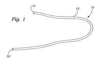
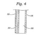
図1〜4は、本発明のガイドカテーテルの種々の実例を示す。図1に示されるように、ガイドカテーテル10は、近位端14および遠位端16を有するガイド本体12を備える。当業者は、本発明のガイドカテーテルが、制限されずに、種々のプラスチック、熱プラスチック、シリコーン、エラストマー、セラミックス、コンポジット材料、または前記材料の種々の組み合わせを含む種々の材料から製造され得ることを認識する。さらに、このガイドカテーテル10は、使用者によって所望されるように、種々の長さおよび幅で製造され得る。図2〜4は、ガイドカテーテル10の種々の実施形態を示す。図2に示されるように、このガイドカテーテル10は、少なくとも1つの内部管腔20を規定する外側壁18を含む。図3〜4は、この外部壁18が内部管腔20を規定し、そしてその中に形成された少なくとも1つの方向付け管腔22を含む代替の実施形態を示す。この縫合付け管腔22は、その中にガイドワイア(図示せず)または操縦デバイス(図示せず)を受容するようなサイズである。別の実施形態では、コイル状ワイア支持体(図示せず)のような少なくとも1つの可撓性支持体構造が、このガイドカテーテル10の外側壁18内に包埋され得る。 1-4 show various examples of the guide catheter of the present invention. As shown in FIG. 1, the
図5は、本発明の治療カテーテル30の実施形態の斜視図を示す。図5に示されるように、この治療カテーテル30は、近位端に位置する治療デバイスハンドル34および遠位端に位置する縫合糸取り付け先端部36を有する細長い本体32を含む。ガイドカテーテル10のガイド本体12のように、所望により、この細長い本体32は、種々の形状、サイズ、長さ、幅、および生物学的に適合性の材料で製造され得る。 FIG. 5 shows a perspective view of an embodiment of the
図6は、本発明治療デバイスハンドル34のより詳細な実例を示す。示されるように、この治療デバイスハンドル34は、少なくとも、吸引コネクター40およびそれに取り付けられた細長い本体受容器42を有するハンドル本体38を備える。この吸引コネクター40は、減圧供給源(図示せず)に接続され得る。この細長い本体受容器42は、その上に細長い本体32(図5)を受容し得る。第1のアクチュエータ44は、このハンドル本体38上に形成された第1のアクチュエータ凹部46内に位置している。同様に、第2のアクチュエータ48は、このハンドル本体38中に形成された第2のアクチュエータ凹部50内に位置している。図6に示されるように、吸引アクチュエータ52は、吸引コネクター40と細長い本体受容器42との間の流体経路を開放または閉鎖する形態であり、上記第1および第2のアクチュエータ44、48に近接するアクチュエータ凹部54内に位置され得る。 FIG. 6 shows a more detailed illustration of the treatment device handle 34 of the present invention. As shown, the treatment device handle 34 includes at least a
図7〜10は、本発明の細長い本体32および縫合糸取り付け先端部36の種々の実例を示す。図7に示されるように、この細長い本体32は、それに近接して位置される第1のニードルポート58Aおよび第2のニードルポート58Bを有する吸引凹部56を含む。この細長い本体32または縫合糸取り付け先端部36は、ガイドワイア62を受容し得るガイドワイアポート60を含み得る。図8Aは、細長い本体32の断面図を示す。示されるように、この細長い本体32は、吸引管腔66を規定する外側壁64を含む。この吸引管腔66は、吸引凹部56(図7)、および治療デバイスハンドル34上に位置する吸引コネクター40(図6)に取り付けられる減圧供給源(図示せず)と流体連通している。その中に位置する第1の針70を有する第1のニードル管腔68は、細長い本体32の外側壁64中に形成されるか、またはそうでなければそれに近接して配置され得る。同様に、その中に位置する第2の針74を有する第1のニードル管腔72は、細長い本体32の外側壁64中に形成されるか、またはそうでなければそれに近接して配置され得る。これらの第1および第2の針70、74は、治療デバイスハンドル34上に位置される第1および第2のアクチュエータ44、48と流体連通する(図6)。この第1および第2のアクチュエータ44、48前方および後方移動は、第1および第2のニードル70、74の長軸方向移動を生じ、それによって、この第1および第2のニードル70、74が第1および第2のニードル管腔68、74から延び、そしてそれに引き込まれることを可能にする。当業者は、この第1および第2のニードル70、74が、個々にまたは同時に移動し得ることを認識する。その中に位置する第1の縫合糸78を有する第1の縫合管腔76、およびその中に位置する第2の縫合糸82を有する第2の縫合管腔80は、細長い本体32の外側壁64内に形成され得るか、またはそれに近接して位置決めされる。勿論、当業者は、本明細書中で「縫合糸」への参照が、まさに伝統的な縫合糸材料のみならず、この組織修復システムの目的を達成するために十分な長さおよび可撓性任意の材料を含み得ることを認識する。1つの実施形態では、その中にガイドワイア62を受容するサイズのガイドワイア管腔84が、細長い本体32の外側壁64内またはその近傍に配置され得、そしてこの縫合糸取り付け先端部36上に形成されたガイドワイアポート60と流体連通し得る。 7-10 show various examples of the
図8A〜8Cは、本発明の代替の実施形態の種々の実例を示し、ここで、膨張可能な位置決めバルーン252は、細長い本体32の外側壁64上に配置される。示されるように、この膨張可能な位置決めバルーン252は、細長い本体32内に配置された膨張管腔84’と流体連通している。この膨張管腔84’は、当業者に公知の様式で膨張供給源と流体連通し得、そしてそうでなれば、治療デバイスハンドル34(図5)と流体連通し、それによって、治療カテーテル30の位置を、ガイドワイアを用いることなく操作され得ることを可能にする。さらに、この位置決めバルーン252は、一旦配置されると、上記治療デバイスを安定して保持するために用いられ得る。 8A-8C illustrate various examples of alternative embodiments of the present invention, where an
図9〜10は、使用前の本発明の種々の実例を示す。示されるように、第1のニードル受容ポート86Aは、第1のニードルポート58Aと同時整列かつ対向する吸引管腔56内またはそれに近接して位置され得る。同様に、第2のニードル受容ポート86Bは、第2のニードルポート58Bと同時整列かつ対向する吸引管腔56内またはそれに近接して位置され得る。第1のニードル受容ポート86Aは、第1の縫合糸管腔76と流体連通しそして少なくともその中に第1の縫合糸78に取り付けられた第1のニードルキャッチ88Aを含む。同様に、第2のニードル受容ポート86Bは、第2のニードルポート58Bに対向する吸引凹部56に近接して配置される。この第2のニードル受容ポート86Bは、その中に第2の縫合糸82に取り付けられた第2のニードルキャッチ88Bを含む。 9-10 show various examples of the present invention prior to use. As shown, the first
図11〜12は、使用の種々のステージの間の本発明の治療カテーテルの実施形態を示す。図11に示されるように、第1のアクチュエータ凹部46(図6)内の第1のアクチュエータ44の前方移動は、第1のニードル70が第1のニードルポート58Aを通って進行し、そして吸引凹部56を横断することを生じる。この第1のアクチュエータ44の継続する作用は、この第1のニードル70が第1のニードル受容ポート86Aを通って進行し、そして第1の縫合糸管腔76内に配置された第1のニードルキャッチ88Aと係合することを生じる。第1のニードルキャッチ88Aは、第1のニードル70と係合し、そしてその上に保持される。使用者は、次いで、第1のニードルを引っ込め得、それによって、縫合凹部56を横切って第1の縫合糸を引く。第1のニードル70を引っ込めるために、使用者は、第1のアクチュエータ44を後方に移動する。図12に示されるように、それに取り付けられた第1のニードルキャッチ88Aを有する第1のニードル70は、第1のニードル受容ポート86Aを通って引っ込められ、吸引凹部56を横断し、そして第1のニードルポート58Aを通って第1のニードル管腔68に入る。図12は、吸引凹部56を横断する第1の縫合糸78を示す。 FIGS. 11-12 illustrate embodiments of the treatment catheter of the present invention during various stages of use. As shown in FIG. 11, the forward movement of the
同様に、図13に示されるように、第2のアクチュエータ48(図6)の前方移動は、第2のニードル74が第2のニードルポート58Bを出ること、およびこの吸引凹部56を横断することにより進行することを生じる。上記に記載の作動プロセスのように、第2のアクチュエータ48の継続する作動は、第2のニードル74が第2のニードル受容ポート86Bを通って進行し、そして第2の縫合糸管腔80内に配置された第2のニードルキャッチ88Bと係合することを生じる。第2のニードルキャッチ88Bは、次いで、第2のニードル74と係合し、そしてその上に保持される。その後、使用者は、第2のニードル74を引っ込め得、それによって、縫合糸凹部の第2のニードルポート58Bを横切って第2の縫合糸を引く。第2のニードル74を引っ込めるために、使用者は、第2のアクチュエータ48を後方に移動する。図14に示されるように、それに取り付けられた第2のニードルキャッチ88Bを有する第2のニードル74は、第2のニードル受容ポート86Bを通って引っ込められ、吸引凹部を横切り、そして第2のニードルポート58Bを通って第2のニードル管腔72に入る。第2のニードルキャッチ88Bに取り付けられる第2の縫合糸82は、従って、吸引凹部56を横断する。 Similarly, as shown in FIG. 13, the forward movement of the second actuator 48 (FIG. 6) causes the
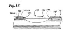
図15は、本発明の代替の実施形態を示す。示されるように、細長い本体32は、その上に形成された吸引凹部90を含み、これは、その中に形成された吸引管腔92と流体連通し、これは、次に、吸引コネクター40(図6)に取り付けられた減圧コネクター40(図6)と流体連通している。第1および第2のニードルポート94A、94Bは、それぞれ、吸引凹部90内またはその近傍に配置される。同様に、第1および第2のニードル受容ポート96A、96Bは、それぞれ、吸引凹部90内またはその近傍に配置され、そして第1および第2のニードルポート94A、94Bと同時整列かつ対向している。第1のニードルポート94Aは第1のニードル管腔98と連通する。それに取り付けられた第1の離脱可能なニードル102を有する第1の配備ロッド100は、第1のニードル管腔98内に配置される。第1の離脱可能なニードル102は、第1のニードル管腔98内に配置される第1の縫合糸104に接続される。同様に、第2のニードルポート94Bは、第2のニードル管腔106と連通する。それに取り付けられた第2の離脱可能なニードル110を有する第2の配備ロッド108は、第2のニードル管腔106内に配置される。第2の離脱可能なニードル110は、第2のニードル管腔106内に配置される第2の縫合糸112に接続される。第1のニードル受容ポート96Aは、吸引凹部90中に形成されるか、またはその近傍に配置される第1のニードルトラップ管腔114Aに至る。その中に第1の離脱可能なニードル102を受容し、かつ保持し得る第1のニードルトラップ116Aは、第1のニードルトラップ管腔114A内に配置される。同様に、第2のニードル受容ポート96Bは、吸引凹部90内に形成されるか、またはそれに近接して配置される第2のニードルトラップ管腔114Bに至る。第1のニードルトラップ116Aと同様に、第2の離脱可能なニードル110をその中に受容かつ保持し得る第2のニードルトラップは、第2のニードルトラップ管腔114B内に配置される。 FIG. 15 shows an alternative embodiment of the present invention. As shown, the
図16〜18は、使用の間の図15の実施形態を示す。第1のアクチュエータ44の前方移動は、第1のニードルロッド100が第1のニードル管腔98から延びることを生じる。図17は、第1のニードルロッド100を示し、それに取り付けられた第1の離脱可能なニードル102が、吸引凹部90を横断して第1のニードルポート94Aを通って延び、そして第1のニードル受容ポート96Aを通って第1のニードルトラップ管腔114A中に入る。第1の検出可能なニードルは、次いで、第1のニードルトラップ116Aと係合する。その後、第1のニードルロッド100は、第1のニードル管腔98中に引っ込められ、それによって、第1の離脱可能なニードル102を第1のニードルトラップ116A中に残す。第1のニードルロッド100を引っ込めるために、使用者は、第1のアクチュエータ44を後方方向に移動し、これは、第1のニードルロッド100を第1のニードル管腔98中に引っ込める。図18は、第1のニードル管腔98中に引っ込められた第1のニードルロッド100を示す。結果として、第1の離脱可能なニードル102に取り付けられている第1の縫合糸104は、吸引凹部90を横断する。当業者は、第2のニードル(図示せず)が同様様式で配備され得ることを認識する。 16-18 show the embodiment of FIG. 15 during use. Forward movement of the
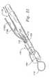
図19〜21は、本発明のファスナーカテーテルの種々の実例を示す。図19に示されるように、このファスナーカテーテル130は、近位端に取り付けられたファスナーカテーテルハンドル134、および遠位端にあるファスナー先端部136を有するファスナーカテーテル本体132を備える。このファスナーカテーテル130は、所望により、種々の形状、サイズ、長さ、幅、および生物学的に適合性の材料で製造され得る。 19-21 show various examples of the fastener catheter of the present invention. As shown in FIG. 19, the
図20は、本発明の好ましいファスナーカテーテルハンドル134のより詳細な実例を示す。示されるように、このファスナーカテーテルハンドル134は、補助コネクター140およびそれに取り付けられたファスナー本体受容器142を有するファスナーハンドル本体138を備える。補助コネクター140は、例えば、減圧供給源または可視化デハイスを含む種々のデバイスに接続されることができてもよい。ファスナー本体コネクター142は、ファスナーカテーテル本体132(図19)を受容し、かつカップルされ得る。ファスナーアクチュエータ144は、ファスナーハンドル本体138上に形成されたファスナーアクチュエータ凹部146内に配置され得る。ファスナーアクチュエータ凹部146内に配置されたファスナーアクチュエータ144は、3つの別個の位置に配置されることができてもよい。例えば、非作動状態では、ファスナーアクチュエータ144は、第1の位置148中に位置され得る。その後、使用者は、第2の位置150にファスナーアクチュエータ144を配置することによりファスナーカテーテル130を部分的に作動し得、それによって、ファスナーカテーテル130(図19)から締結デバイス(図示せず)を配備する。使用者は、次いで、ファスナーカテーテル130を、ファスナーアクチュエータ凹部146内の第3の位置152にファスナーアクチュエータ144を移動することにより完全に作動し、それによって、ファスナー先端部136上またはその近位方向にある切断部材(以下に論議される)を作動する。 FIG. 20 shows a more detailed illustration of a preferred fastener catheter handle 134 of the present invention. As shown, the fastener catheter handle 134 includes a
図21aおよび21bは、分解組立図の様式で、ファスナー先端部136の片を示す。内部本体154は、その側面に形成された縫合糸凹部160を含み、これは、次いで、内部ファスナー管腔158と連通する。内部本体154はまた、それから半径方向外側に延びるピン162を含む。スリーブ156は、その中に内部本体154を受容するに十分な直径の軸方向配備管腔166を備える。スリーブ156はまた、その軸方向側面に形成された切断凹部168、および切断凹部168の近位エッジ上に切断部材170を備える。スロット172は配備管腔166の軸に平行に延び、そしてファスナー管腔を通って半径方向に延び得る。ピン凹部172は、ピン162をスライドする関係で受容する。 21a and 21b show a piece of
図23〜24は、本発明のファスナー180を示す。ファスナー180は、例えば、ニッケル−チタン合金、形状記憶合金、ステンレス鋼、チタン、種々のプラスチック、およびその他の生物学的に適合性の材料を含む種々の材料から製造され得る。ファスナー180は、それを通って軸方向に延びる内部管腔188、およびその端部上に形成された1つ以上の係合部材184を有する。これら係合部材の間には、取り付け管腔188と連通している規定された係合アパーチャ186がある。取り付け管腔188および係合アパーチャ186は、その中に第1の縫合糸リード176Aおよび第2の縫合糸リード176Bを受容するサイズである。配備に先立ち、係合部材(単数または複数)184は、ファスナー180の軸から半径方向に離れて、係合アパーチャ186がそれを通じて縫合リード176Aおよび176Bがスライドすることを許容するに十分な比較的大きな第1の直径を有するように反る。配備に際し、すなわち、縫合糸176Aおよび176Bが引っ込められた後、係合部材184は反るか、または係合アパーチャ186が、第2のより小さな直径をとり、縫合糸リード176Aおよび176Bをその場に固定するようにデバイスの軸に向かって跳ね返ることを許容する。好ましくは、係合部材184(単数または複数)は、ファスナー180の軸の自然な位置に向かって跳ねる傾向にある。図24は、配備された形態にあるファスナー180を示し、そこでは、縫合糸ループ178が、2つの目立たない組織部分200A、200Bを通過し、そして縫合糸リード176A、176Bが、ファスナー180中に固定される。各係合部材184は、先のとがった先端部190をさらに含み得、これは、係合部材(単数または複数)が配備位置にあるとき、縫合糸リード176A、176Bと係合し、そしてそれらの動きをさらに制限する。 23-24 show a
それに取り付けられたファスナー180をもち、そして配備の準備ができた、作動するファスナー先端部136が図22に見られ得る。内部本体154は、スリーブ156の内側に、縫合糸凹部160が切断凹部168と整列するように配置される。ピン172は、スロット162とスライド可能に連通しており、それによって、内部本体154とスリーブ156との間の、相対的な直線運動を許容はするが、相対的な回転運動は防ぐ。ファスナー180は、係合部材184を半径方向外側に、それらが、内部本体154の外側周縁の周りに配置され得るまで反ることにより、ファスナー先端部136の端部上に配置されている。従って、ファナスーは、内部本体154の端部に、係合部材184と内部本体154の外側表面との間の摩擦係合により固定される。縫合糸ループ178は、ファスナー180から延びる。縫合糸リード176Aおよび176Bは、管腔188を通って延び、係合アパーチャ186を通り、縫合凹部160を通って内部本体154の側面から出て、そして切断凹部168を通ってスリーブ156の側面から出る。 A working
ファスナーの配備は、2ステッププロセスである。一旦、縫合糸178が1つ以上の組織セグメントを通って固定されると、ファスナー先端部136は、組織に向かって誘導され、そして縫合糸リード176Aおよび176Bは、縫合糸ループが標的組織の周りに十分締め上げられるまで、組織から離れて引かれる。スリーブ156が、次いで、内部本体154が軸方向に離れて引かれながら、組織に隣接する場所に保持される。これは、スリーブ156が、ファスナー180を内部本体154の外側表面から離れて押す(すなわち、スライドする)ようにする。ファスナー180が、内部本体154から完全に除去されるとき、係合部材184は、軸方向に内側に跳ね、それによって、係合アパーチャ186の直径を減じ、そして縫合糸リード176aおよび176Bを固定する。縫合糸リード176Aおよびも176Bを切断する、第2番目の配備ステップは、縫合リードが縫合糸凹部160の先導エッジと切断部材170との間でつままれ、そして最終的に切断部材170によって切断されるという、内部本体154がスリーブ156を通って十分引かれときに達成される。 Fastener deployment is a two-step process. Once
ファスナー180の遠隔配備は、内部本体154をファスナーアクチュエータ144に取り付けること、およびスリーブ156をファスナーカテーテルハンドル134に取り付けることによって達成される。従って、ファスナーアクチュエータ144のハンドル134に対する軸方向移動は、内部本体154とスリーブ156との間で類似の相対的移動を引き起こす。例えば、非作動位置148では(図20を参照のこと)、内部本体154の遠位端は、スリーブ156から十分な距離延び、その上にファスナー180を保持する。第2の位置150では、内部本体154は、スリーブ156中に十分な距離引かれてファスナー180を配備し、そして第3の位置152では、内部本体154は十分な距離引かれて縫合糸リード176Aおよび176Bを切断する。 Remote deployment of the
本発明はまた、インビボで目立たない組織部分を修復するために、開示された僧帽弁修復システムを用いる種々の方法を開示する。以下の段落は、機能不全僧帽弁を修復する方法を記載しているが、当業者は、本発明および手順が、その他の弁に対し、または2つ以上の組織片の付着を必要とするその他の手順での使用に適合され得ることを認識する。 The present invention also discloses various methods of using the disclosed mitral valve repair system to repair inconspicuous tissue portions in vivo. The following paragraphs describe a method for repairing a dysfunctional mitral valve, but those skilled in the art will appreciate that the present invention and procedure require the attachment of other valves or more than one piece of tissue. Recognize that it can be adapted for use in other procedures.
機能不全またはそうでなければ不能心臓弁を修復するために、循環系を横切り得、そして患者の心臓に侵入し得るガイドワイアが、血管内進入点を通って患者に導入される。例えば、この血管内進入点は、大腿静脈または右頚静脈中に形成され得る。その後、ガイドワイアが循環系を通って進行され、最終的に心臓に到達する。このガイドワイアは、右心房に方向付けられ、右心房を横断し、そして経中隔ニードルまたは予め存在する穴の支援にもより穿孔を作製し、それによって左心房に入る。図25に示されるように、ガイドワイア220は、次いで、僧帽弁222を通り、そして左心室226に進行する。ガイドワイア220は、大動脈片228を大動脈230まで横断し、そして血管内出口点を通って大腿動脈で出現するようにされる。一旦、ガイドワイア220が配置されると、血管内入口ポートまたは出口ポートが広げられ、それを通ってカテーテルの進入を許容する。保護シースが、血管構造を保護するために静脈領域中を進行され得る。 To repair a dysfunctional or otherwise impossible heart valve, a guide wire that can traverse the circulatory system and enter the patient's heart is introduced into the patient through an intravascular entry point. For example, this intravascular entry point can be formed in the femoral vein or the right jugular vein. The guide wire is then advanced through the circulatory system and eventually reaches the heart. This guidewire is directed to the right atrium, traverses the right atrium and creates a perforation with the aid of a transseptal needle or pre-existing hole, thereby entering the left atrium. As shown in FIG. 25, guidewire 220 then advances through
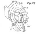
図26に示されるように、本発明のガイドカテーテル10は、ガイドワイア220に取り付けられ得、そして広げられたガイドワイア入口ポートを通り、僧帽弁222に近接する点まで進行される。当業者は、本発明の僧帽弁修復システムが、使用者によって所望のように、順方向位置から、または逆方向位置から僧帽弁に接近し得ることを認識する。一旦、ガイドカテーテルが、心臓内に適切に配置されると、上記治療カテーテル30が、ガイドカテーテル10を通り、僧帽弁222の近位方向の位置に進行され得る。図27は、僧帽弁222の近位方向にあるガイドカテーテル10から出現する治療カテーテル30を示す。その後、使用者は、治療デバイスハンドル34(図6)のハンドル本体38上に位置する吸引アクチュエータ52を作動し得る。結果として、吸引力が、治療カテーテル30(図7)の縫合糸取り付け先端部36上に形成された吸引凹部56から、それに対し近位方向に位置する組織に付与される。図28に示されるように、第1の弁小葉240Aは、吸引凹部56を通じて付与された吸引力によって係合および保持される。第1の弁小葉240Aを安定化し、使用者は、それに対し、上記に記載のように、縫合糸242Aを付与し得る。第1の縫合糸を第1の弁小葉240Aに付与するために、使用者は、治療デバイスハンドル34上に位置する第1のアクチュエータ44を作動し、これは、第1のニードル70が第1の弁小葉240Aを通って進行させ、そして第1のニードルキャッチ88Aを係合および保持し、それによって、第1の縫合糸242Aを組織に付与する(図6〜7)。その後、使用者は、第1の弁小葉240Aへの吸引力の付与を停止し得、それによって縫合された組織を解放する。図29は、それに付与された第1の縫合糸242Aを有する第1の弁小葉240Aを示す。図30に示されるように、治療カテーテル30は、次いで、回転され得、そして第2の弁小葉240Bを係合するように配置される。ここで再び、使用者は、吸引アクチュエータ52を作動し得、吸引力を、吸引凹部56を通じて第2の弁小葉240Bに付与する。図30に示されるように第2の弁小葉240Bが安定化され、使用者は、第2縫合糸242Bをそれに対し、治療デバイスハンドル34上に位置する第2のアクチュエータ48を作動することにより付与し得、これは、第2のニードル74が第2の弁小葉240Bを通って進行し、そして第2のニードルチャッチ88Bを保持し、それによって、第2の縫合糸242Bを組織に付与する。図31に示されるように、使用者は、安定化された組織への吸引の付与を停止し得、そして治療カテーテルを患者から取り除き、それによって、第1および第2の縫合糸242A、242Bを第1および第2の弁小葉240A、240Bに取り付けて残す。第1および第2の縫合糸242Aおよび242Bは、治療カテーテルが除去されるとき、弁小葉240Aおよび240Bを通る単一ループが存在するように事実上同一縫合糸の部分であることに注目のこと。 As shown in FIG. 26, the
図32〜33に示されるように、ファスナーカテーテル130はガイドワイア220に取り付けられ、そして第1および第2の縫合糸242A、242Bに取り付けられる。その後、ファスナーカテーテル130は、ガイドカテーテル10に挿入され、そして僧帽弁222の近位方向の位置に進められる。使用者は、次いで、ファスナーカテーテル130を僧帽弁22に進行しながら、第1および第2の縫合糸242A、242Bをピンと張って引き、それによって、第1および第2の弁小葉240A、240B間の距離を減少する。使用者は、次いで、ファスナーアクチュエータ144を作動し、これは、スリーブ156を、上記のように、これら小葉に隣接する第1および第2の縫合糸242A、242Bにファスナー180を係合および付与される。ファスナーアクチュエータ144の継続する作動は、切断部材170を、第1および第2の縫合糸242A、242Bと係合および切断させる。図34に示されるように、ファスナーカテーテル130、ガイドカテーテル10、およびガイドワイア220が患者から除去された後、ファスナー180は、僧帽弁222に付与されて残る。 As shown in FIGS. 32-33, the
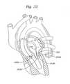
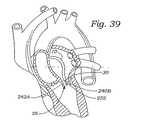
図35〜44は、組織、特に、この実施形態ではインビボの弁小葉を修復する代替の方法を記載する。図35〜37に示されるように、ガイドカテーテル10は、循環システムを通り、心臓の右心房まで進行する。一旦、配置されると、開創器250がガイドカテーテル10を通って進行され、そして心房中隔を穿孔するようにされ、それによって、左心房に入る。その後、ガイドカテーテル10が穿孔された心房中隔を通って左心房中に進行し、そして僧帽弁222の近位方向に配置される。図38に示されるように、治療カテーテル30は、ガイドカテーテル10中に挿入され、そして僧帽弁222の近位方向の位置に進行される。図39に示されるように、治療カテーテル30上に位置する膨張可能な位置決めバルーン252(上記で論議したような)が膨張されてカテーテルを配向かつ安定にする。治療デバイスハンドル34上の吸引アクチュエータ52が、次いで作動され、吸引凹部56(図6を参照のこと)に吸引力を付与する。この膨張したバルーン252は、第2の弁小葉240Bと係合し、これは、吸引凹部56を第1の弁小葉240Aに向かって押し、それによって、図40に示されるように第1の弁小葉240Aの安定化を生じる。図41に示されるように、使用者は、次いで、上記のように、第1の縫合糸242Aを第1の弁小葉240Aに付与し得る。一旦、縫合糸が付与されると、使用者は、膨張可能な位置決めバルーン252を萎ませ得、そして治療カテーテル30を約180゜回転する。その後、使用者は、位置決めバルーン252を膨張し、そして吸引アクチュエータ52を作動し、吸引凹部56に吸引力を付与する。図42に示されるように、この膨張可能な位置決めバルーン252を再び膨張し、そして第1の弁小葉240と係合させ、それによって、吸引凹部56を押し、第2の弁小葉240Bと係合し、そして図42に示されるように、第2の弁小葉240Bの安定化を許容する。その後、使用者は、上記のように、第2の縫合糸242Bを第2の弁小葉240Bに付与する。図43〜44は、それに付与された第1および第2の縫合糸242A、242Bを有する第1および第2の弁小葉240A、240Bを示す。その後、治療カテーテル30は、患者身体から除去され、そしてファスナーカテーテル130が、上記のように、ファスナーを第1および第2の縫合糸242A、242Bを付与するために用いられる。 FIGS. 35-44 describe an alternative method of repairing tissue, particularly valve leaflets in vivo in this embodiment. As shown in FIGS. 35-37, the
終わりにあたり、本明細書中に開示された本発明の実施形態は、本発明の原理の例示であることが理解される。その他の改変が採用され得、これらは本発明の範囲内にある。従って、本発明は、本開示に示されおよび説明された実施形態に制限されない。 At the end, it is understood that the embodiments of the invention disclosed herein are illustrative of the principles of the present invention. Other modifications may be employed and are within the scope of the present invention. Accordingly, the present invention is not limited to the embodiments shown and described in this disclosure.
Claims (23)
Translated fromJapanese近位端、遠位端、およびその中に形成された内部管腔を有するガイドカテーテルであって、該内部管腔が該ガイドカテーテルの近位端および遠位端と連通しているガイドカテーテル;
該組織に縫合糸を付与し得る治療カテーテルであって、該ガイドカテーテルの内部管腔を横断し得る治療カテーテル;ならびに
該縫合糸にファスナーを取り付け得るファスナーカテーテルであって、該ガイドカテーテルの内部管腔を横断し得るファスナーカテーテルを備える、システム。A system for repairing tissue in a patient's heart, comprising:
A guide catheter having a proximal end, a distal end, and an inner lumen formed therein, wherein the inner lumen is in communication with the proximal and distal ends of the guide catheter;
A treatment catheter capable of applying a suture to the tissue, the treatment catheter capable of traversing the inner lumen of the guide catheter; and a fastener catheter capable of attaching a fastener to the suture, the inner tube of the guide catheter A system comprising a fastener catheter that can traverse a cavity.
近位端と遠位端とその中に形成された吸引管腔を有する細長い本体;
該細長い本体の遠位部分に形成された吸引凹部であって、該吸引管腔と流体連通している吸引凹部;
該細長い本体中に形成されたニードル管腔であって、その中に配置されたニードルを有するニードル管腔;
該吸引凹部に近接する該細長い本体の遠位端に配置されたニードルポートであって、該ニードル管腔と連通するニードルポート;
該細長い本体内に形成された縫合糸管腔;
該縫合糸管腔と連通し、かつ該吸引凹部に近接して配置される受容ポートであって、該ニードルポートと同時配列され、かつ対向する受容ポート;および
該ニードルに取り付けられたアクチュエータを備える、請求項1に記載のシステム。The treatment catheter comprises:
An elongate body having a proximal end and a distal end and a suction lumen formed therein;
A suction recess formed in a distal portion of the elongate body, the suction recess in fluid communication with the suction lumen;
A needle lumen formed in the elongated body, the needle lumen having a needle disposed therein;
A needle port disposed at a distal end of the elongate body proximate the suction recess, the needle port communicating with the needle lumen;
A suture lumen formed in the elongated body;
A receiving port in communication with the suture lumen and disposed proximate to the suction recess, the receiving port being co-aligned with and opposed to the needle port; and an actuator attached to the needle The system of claim 1.
近位端および遠位端を有し、その中に形成された吸引管腔を有する細長い本体;
該細長い本体の遠位部分に形成された吸引凹部であって、吸引凹部が該吸引管腔と連通している吸引凹部;
該細長い本体に形成されたニードル管腔;
該細長い本体の遠位端に配置され、かつ該吸引凹部に近接して位置決めされ、該ニードル管腔と連通しているニードルポート;
ニードル配備部材に連結された離脱可能なニードルであって、該離脱可能なニードルおよび該ニードル配備部材は該ニードル管腔内に配置され、縫合糸材料の供給源に連結された離脱可能なニードル;
該吸引凹部に近接して配置されたニードルトラップポートであって、該ニードルポートと同時配列かつ対向するニードルトラップポート;
該ニードルトラップポート内に配置されるニードルトラップ;および
該ニードルに取り付けられたアクチュエータを備える、請求項1に記載のシステム。The treatment catheter is:
An elongate body having a proximal end and a distal end and having a suction lumen formed therein;
A suction recess formed in a distal portion of the elongate body, wherein the suction recess communicates with the suction lumen;
A needle lumen formed in the elongated body;
A needle port disposed at a distal end of the elongate body and positioned proximate to the suction recess and in communication with the needle lumen;
A removable needle coupled to a needle deployment member, wherein the removable needle and the needle deployment member are disposed within the needle lumen and coupled to a source of suture material;
A needle trap port disposed proximate to the suction recess, the needle trap port being simultaneously arranged and opposed to the needle port;
The system of claim 1, comprising a needle trap disposed within the needle trap port; and an actuator attached to the needle.
近位端、遠位端、およびその中に形成された内部管腔を有するガイドカテーテルであって、該内部管腔が該近位端および遠位端と流体連通しているガイドカテーテル;
近位端および遠位端を有する治療カテーテルであって、該遠位端が、その上に配置された吸引凹部、その上ニードルポートおよび少なくとも1つの同時整列かつ対向する受容ポート、該ニードルポートと連通するニードル管腔を有し、該ニードル管腔がその中にニードルを有し、該ガイドカテーテル内に軸方向に受容されるサイズの治療カテーテル;および
それに離脱可能に連結されるファスナーおよびその上に配置された切断部材を有するファスナーカテーテルであって、該ガイドカテーテル内に受容されるサイズのファスナーカテーテルを備える、システム。A system for repairing tissue in a patient's heart, comprising:
A guide catheter having a proximal end, a distal end, and an inner lumen formed therein, wherein the inner lumen is in fluid communication with the proximal end and the distal end;
A treatment catheter having a proximal end and a distal end, the distal end having a suction recess disposed thereon, an upper needle port and at least one simultaneously aligned and opposed receiving port, the needle port A therapeutic catheter of a size having a communicating needle lumen, the needle lumen having a needle therein and axially received within the guide catheter; and a fastener removably coupled thereto and above A fastener catheter having a cutting member disposed on the guide catheter, the fastener catheter being sized to be received within the guide catheter.
患者中に挿入され、かつ循環経路を通じて進行し得るガイドワイア;
該ガイドワイアに取り付け可能であり、かつ該組織に縫合糸を付与し得る治療カテーテル;および
該ガイドワイアに取り付け可能であり、かつ該縫合糸にファスナーを取り付け得るファスナーカテーテルを備える、システム。A system for repairing tissue in a patient's heart:
A guidewire that can be inserted into the patient and travel through the circulatory pathway;
A treatment catheter attachable to the guidewire and capable of providing a suture to the tissue; and a fastener catheter attachable to the guidewire and capable of attaching a fastener to the suture.
近位端および遠位端を有し、該遠位端がその上に形成された吸引凹部を有する細長い本体;
該吸引凹部に近接して配置されたニードルポート;
該ニードルポートと連通するニードル管腔であって、その中の配置されたニードルを有するニードル管腔;
該吸引凹部に近接して配置された受容ポートであって、該受容ポートが該ニードルポートと同時整列かつ対向し、その中に該ニードルを受容かつ保持し得るニードルキャッチを有し、該ニードルキャッチが縫合糸材料の供給源に取り付けられる受容ポート;および
該ニードルと連通する少なくとも1つのアクチュエータ部材を備える、カテーテル。A catheter for delivering a suture to tissue within a patient's heart, comprising:
An elongate body having a proximal end and a distal end, the distal end having a suction recess formed thereon;
A needle port disposed proximate to the suction recess;
A needle lumen in communication with the needle port, the needle lumen having a needle disposed therein;
A receiving port disposed proximate to the suction recess, the receiving port being co-aligned and opposed to the needle port and having a needle catch capable of receiving and holding the needle therein, the needle catch A catheter comprising: a receiving port attached to a source of suture material; and at least one actuator member in communication with the needle.
近位端および遠位端を有し、該遠位端がその上に形成された吸引凹部を有する、細長い本体;
該吸引凹部に近接して配置されたニードルポート;
該ニードルポートと連通するニードル管腔であって、該ニードル管腔内に配置された縫合糸材料に取り付けられた離脱可能なニードルを有するニードル管腔;
該吸引凹部に近接して位置する受容ポートであって、該ニードル受容ポートが該ニードルポートと同時整列かつ対向し、その中に該離脱可能なニードルを受容し得るニードルトラップを有し、該ニードルトラップが縫合糸材料の供給源に取り付けられるニードル受容ポート;および
該ニードルと連通するアクチュエータ部材を備える、カテーテル。A catheter for delivering a suture to tissue within a patient's heart, comprising:
An elongate body having a proximal end and a distal end, the distal end having a suction recess formed thereon;
A needle port disposed proximate to the suction recess;
A needle lumen in communication with the needle port, the needle lumen having a removable needle attached to a suture material disposed within the needle lumen;
A receiving port located proximate to the suction recess, the needle receiving port being simultaneously aligned and opposed to the needle port, and having a needle trap capable of receiving the removable needle therein, the needle A catheter comprising: a needle receiving port where the trap is attached to a source of suture material; and an actuator member in communication with the needle.
近位端および遠位端を有し、該遠位端がその上に形成された吸引凹部を有する細長い本体:
該細長い本体内に配置された膨張管腔;
該細長い本体の遠位端上に配置された膨張位置決めバルーンであって、該膨張管腔と流体連通する膨張位置決めバルーン;
該吸引凹部に近接して位置するニードルポート;
該ニードルポートと連通するニードル管腔であって、その中に配置された縫合糸材料
取り付けられた離脱可能なニードルを有するニードル管腔;
該吸引凹部に近接して位置するニードル受容ポートであって、該ニードルポートと同時整列かつ対向し、その中に該離脱可能なニードルを受容し得るニードルトラップを有し、該ニードルトラップが縫合糸材料の供給源に取り付けられるニードル受容ポート;および
該ニードルと連通するアクチュエータ部材を備える、カテーテル。A catheter for delivering a suture to tissue within a patient's heart, comprising:
An elongate body having a proximal end and a distal end, the distal end having a suction recess formed thereon:
An inflation lumen disposed within the elongate body;
An inflation positioning balloon disposed on a distal end of the elongate body, wherein the inflation positioning balloon is in fluid communication with the inflation lumen;
A needle port located close to the suction recess;
A needle lumen in communication with the needle port, the needle lumen having a removable needle mounted therein with a suture material attached;
A needle receiving port located proximate to the suction recess and having a needle trap that is simultaneously aligned and opposed to the needle port and capable of receiving the removable needle therein, the needle trap being a suture A needle receiving port attached to a source of material; and an actuator member in communication with the needle.
その中に形成された取り付け管腔を有するファスナー本体であって、該取り付け管腔は、その中に縫合糸を受容し得るファスナー本体;および
該ファスナー本体に取り付けられる係合部材であって、該係合部材は、該縫合糸材料を係合および保持し得、係合アパーチャを規定し、該係合アパーチャが該取り付け管腔と連通している係合部材を備える、縫合糸ファスナー。A suture fastener attachable to a suture material comprising:
A fastener body having an attachment lumen formed therein, the attachment lumen being a fastener body capable of receiving a suture therein; and an engagement member attached to the fastener body, A suture fastener comprising an engagement member that can engage and retain the suture material, defines an engagement aperture, and the engagement aperture is in communication with the attachment lumen.
ガイドカテーテルを、循環経路を通じて心臓弁に近接する心臓内の位置に進行する工程;
該ガイドカテーテルを通じて該心臓弁に治療カテーテルを進行する工程;
該治療カテーテルで第1の小葉を安定化する工程;
第1の縫合糸材料を、該安定化された第1の小葉中に配備する工程;
該第1の小葉を、該治療カテーテルから、該第1の縫合糸材料をそれに取り付けたままにしながら解放する工程;
第2の小葉を該治療カテーテルで安定化する工程;
第2の縫合糸材料を、該第2の小葉中に配備する工程;
該第2の小葉を、該治療カテーテルから、該第2の縫合糸材料をそれに取り付けたままにしながら解放する工程;
該ガイドカテーテルから該治療カテーテルを除去する工程;
ファスナーカテーテルを、該第1および第2の縫合糸材料に沿って、該ガイドカテーテルを通って該心臓弁まで進行する工程;および
該第1の縫合糸と第2の縫合糸との間の距離を、該ファスナーカテーテルから配備されたファスナーで減少することにより、該第1の小葉および第2の小葉を接続する工程、を包含する、方法。A method of repairing tissue in a patient's heart, comprising:
Advancing the guide catheter through the circulation path to a location in the heart proximate to the heart valve;
Advancing a treatment catheter through the guide catheter to the heart valve;
Stabilizing the first leaflet with the treatment catheter;
Deploying a first suture material into the stabilized first leaflet;
Releasing the first leaflet from the treatment catheter while leaving the first suture material attached thereto;
Stabilizing a second leaflet with the treatment catheter;
Deploying a second suture material into the second leaflet;
Releasing the second leaflet from the treatment catheter while leaving the second suture material attached to it;
Removing the treatment catheter from the guide catheter;
Advancing a fastener catheter along the first and second suture materials through the guide catheter to the heart valve; and a distance between the first and second sutures Connecting the first and second leaflets by reducing with a fastener deployed from the fastener catheter.
ガイドカテーテルを、循環経路を通り、心臓弁に近接する心臓内の位置まで進行する工程;
治療カテーテルを、該ガイドカテーテルを通り、該心臓弁まで進行する工程;
該治療カテーテル上の膨張可能な位置決めバルーンを膨張する工程;
第2の小葉を該膨張可能な位置決めバルーンと係合し、それによって、該治療カテーテルを第1の小葉に向ける工程;
該第1の小葉を該治療カテーテルで安定化する工程;
第1の縫合糸材料を安定化された該第1の小葉中に配備する工程;
該第1の小葉を、該治療カテーテルから、該第1の縫合糸材料をそれに取り付けたままにしながら解放する工程;
該第1の小葉を該膨張可能な位置決めバルーンと係合し、それによって、該治療カテーテルを第2の小葉に向ける工程;
第2の小葉を該治療カテーテルで安定化する工程;
第2の縫合糸材料を、該第2の小葉中に配備する工程;
該第2の小葉を、該治療カテーテルから、該第2の縫合糸材料をそれに取り付けたままにしながら解放する工程;
該膨張可能な位置決めバルーンを萎ませる工程;
該ガイドカテーテルから該治療カテーテルを除去する工程;
ファスナーカテーテルを、該第1および第2の縫合糸材料に沿って、該ガイドカテーテルを通って該心臓弁まで進行する工程;および
該第1の縫合糸と第2の縫合糸との間の距離を、該ファスナーカテーテルから配備されたファスナーで減少することにより、該第1の小葉および第2の小葉を接続する工程、を包含する、方法。A method of repairing tissue in a patient's heart, comprising:
Traveling the guide catheter through the circulation path to a position in the heart proximate to the heart valve;
Advancing a treatment catheter through the guide catheter to the heart valve;
Inflating an inflatable positioning balloon on the treatment catheter;
Engaging a second leaflet with the inflatable positioning balloon, thereby directing the treatment catheter to the first leaflet;
Stabilizing the first leaflet with the treatment catheter;
Deploying a first suture material into the stabilized first leaflet;
Releasing the first leaflet from the treatment catheter while leaving the first suture material attached thereto;
Engaging the first leaflet with the inflatable positioning balloon, thereby directing the treatment catheter to the second leaflet;
Stabilizing a second leaflet with the treatment catheter;
Deploying a second suture material into the second leaflet;
Releasing the second leaflet from the treatment catheter while leaving the second suture material attached to it;
Deflating the inflatable positioning balloon;
Removing the treatment catheter from the guide catheter;
Advancing a fastener catheter along the first and second suture materials through the guide catheter to the heart valve; and a distance between the first suture and a second suture Connecting the first leaflet and the second leaflet by reducing with a fastener deployed from the fastener catheter.
Applications Claiming Priority (2)
| Application Number | Priority Date | Filing Date | Title |
|---|---|---|---|
| US10/389,721US7381210B2 (en) | 2003-03-14 | 2003-03-14 | Mitral valve repair system and method for use |
| PCT/US2004/007383WO2004082523A2 (en) | 2003-03-14 | 2004-03-11 | Mitral valve repair system |
Publications (3)
| Publication Number | Publication Date |
|---|---|
| JP2006520240Atrue JP2006520240A (en) | 2006-09-07 |
| JP2006520240A5 JP2006520240A5 (en) | 2007-06-14 |
| JP4558718B2 JP4558718B2 (en) | 2010-10-06 |
Family
ID=32962331
Family Applications (1)
| Application Number | Title | Priority Date | Filing Date |
|---|---|---|---|
| JP2006507062AExpired - Fee RelatedJP4558718B2 (en) | 2003-03-14 | 2004-03-11 | Mitral valve repair system and method for use |
Country Status (6)
| Country | Link |
|---|---|
| US (4) | US7381210B2 (en) |
| EP (2) | EP2401970B1 (en) |
| JP (1) | JP4558718B2 (en) |
| AU (1) | AU2004222384A1 (en) |
| CA (2) | CA2518962C (en) |
| WO (1) | WO2004082523A2 (en) |
Cited By (2)
| Publication number | Priority date | Publication date | Assignee | Title |
|---|---|---|---|---|
| JP2012513249A (en)* | 2008-12-22 | 2012-06-14 | コーディス・コーポレイション | A deflection guide catheter used in minimally invasive medical procedures for mitral regurgitation therapy |
| JP2013512013A (en)* | 2009-11-27 | 2013-04-11 | トランスカテーテル テクノロギース ゲーエムベーハー | Apparatus, set and method for folding or unfolding a medical implant |
Families Citing this family (497)
| Publication number | Priority date | Publication date | Assignee | Title |
|---|---|---|---|---|
| EP0850607A1 (en) | 1996-12-31 | 1998-07-01 | Cordis Corporation | Valve prosthesis for implantation in body channels |
| US6050936A (en) | 1997-01-02 | 2000-04-18 | Myocor, Inc. | Heart wall tension reduction apparatus |
| US6406420B1 (en) | 1997-01-02 | 2002-06-18 | Myocor, Inc. | Methods and devices for improving cardiac function in hearts |
| FR2768324B1 (en) | 1997-09-12 | 1999-12-10 | Jacques Seguin | SURGICAL INSTRUMENT FOR PERCUTANEOUSLY FIXING TWO AREAS OF SOFT TISSUE, NORMALLY MUTUALLY REMOTE, TO ONE ANOTHER |
| US6332893B1 (en) | 1997-12-17 | 2001-12-25 | Myocor, Inc. | Valve to myocardium tension members device and method |
| US6260552B1 (en) | 1998-07-29 | 2001-07-17 | Myocor, Inc. | Transventricular implant tools and devices |
| US7235087B2 (en) | 1999-03-04 | 2007-06-26 | Abbott Park | Articulating suturing device and method |
| US7842048B2 (en) | 2006-08-18 | 2010-11-30 | Abbott Laboratories | Articulating suture device and method |
| US7001400B1 (en) | 1999-03-04 | 2006-02-21 | Abbott Laboratories | Articulating suturing device and method |
| US20040092964A1 (en) | 1999-03-04 | 2004-05-13 | Modesitt D. Bruce | Articulating suturing device and method |
| US8137364B2 (en) | 2003-09-11 | 2012-03-20 | Abbott Laboratories | Articulating suturing device and method |
| US6964668B2 (en) | 1999-03-04 | 2005-11-15 | Abbott Laboratories | Articulating suturing device and method |
| US7226467B2 (en) | 1999-04-09 | 2007-06-05 | Evalve, Inc. | Fixation device delivery catheter, systems and methods of use |
| US8216256B2 (en) | 1999-04-09 | 2012-07-10 | Evalve, Inc. | Detachment mechanism for implantable fixation devices |
| US20040044350A1 (en) | 1999-04-09 | 2004-03-04 | Evalve, Inc. | Steerable access sheath and methods of use |
| US7811296B2 (en) | 1999-04-09 | 2010-10-12 | Evalve, Inc. | Fixation devices for variation in engagement of tissue |
| US10327743B2 (en) | 1999-04-09 | 2019-06-25 | Evalve, Inc. | Device and methods for endoscopic annuloplasty |
| US6752813B2 (en) | 1999-04-09 | 2004-06-22 | Evalve, Inc. | Methods and devices for capturing and fixing leaflets in valve repair |
| AU770243B2 (en) | 1999-04-09 | 2004-02-19 | Evalve, Inc. | Methods and apparatus for cardiac valve repair |
| ATE329531T1 (en) | 1999-07-02 | 2006-07-15 | Quickpass Inc | SURGICAL SEWING DEVICE |
| US6440164B1 (en) | 1999-10-21 | 2002-08-27 | Scimed Life Systems, Inc. | Implantable prosthetic valve |
| US7842068B2 (en) | 2000-12-07 | 2010-11-30 | Integrated Vascular Systems, Inc. | Apparatus and methods for providing tactile feedback while delivering a closure device |
| US6391048B1 (en) | 2000-01-05 | 2002-05-21 | Integrated Vascular Systems, Inc. | Integrated vascular device with puncture site closure component and sealant and methods of use |
| US6461364B1 (en) | 2000-01-05 | 2002-10-08 | Integrated Vascular Systems, Inc. | Vascular sheath with bioabsorbable puncture site closure apparatus and methods of use |
| US8758400B2 (en) | 2000-01-05 | 2014-06-24 | Integrated Vascular Systems, Inc. | Closure system and methods of use |
| US9579091B2 (en) | 2000-01-05 | 2017-02-28 | Integrated Vascular Systems, Inc. | Closure system and methods of use |
| US6454799B1 (en) | 2000-04-06 | 2002-09-24 | Edwards Lifesciences Corporation | Minimally-invasive heart valves and methods of use |
| US7083628B2 (en) | 2002-09-03 | 2006-08-01 | Edwards Lifesciences Corporation | Single catheter mitral valve repair device and method for use |
| SE0002878D0 (en)* | 2000-08-11 | 2000-08-11 | Kimblad Ola | Device and method of treatment of atrioventricular regurgitation |
| DE60144328D1 (en) | 2000-09-08 | 2011-05-12 | Abbott Vascular Inc | Surgical clamp |
| US6723038B1 (en) | 2000-10-06 | 2004-04-20 | Myocor, Inc. | Methods and devices for improving mitral valve function |
| US6626918B1 (en) | 2000-10-06 | 2003-09-30 | Medical Technology Group | Apparatus and methods for positioning a vascular sheath |
| US6602286B1 (en) | 2000-10-26 | 2003-08-05 | Ernst Peter Strecker | Implantable valve system |
| US7905900B2 (en) | 2003-01-30 | 2011-03-15 | Integrated Vascular Systems, Inc. | Clip applier and methods of use |
| US7211101B2 (en) | 2000-12-07 | 2007-05-01 | Abbott Vascular Devices | Methods for manufacturing a clip and clip |
| US6695867B2 (en) | 2002-02-21 | 2004-02-24 | Integrated Vascular Systems, Inc. | Plunger apparatus and methods for delivering a closure device |
| US8690910B2 (en) | 2000-12-07 | 2014-04-08 | Integrated Vascular Systems, Inc. | Closure device and methods for making and using them |
| US6623510B2 (en) | 2000-12-07 | 2003-09-23 | Integrated Vascular Systems, Inc. | Closure device and methods for making and using them |
| US6733525B2 (en) | 2001-03-23 | 2004-05-11 | Edwards Lifesciences Corporation | Rolled minimally-invasive heart valves and methods of use |
| US7556646B2 (en) | 2001-09-13 | 2009-07-07 | Edwards Lifesciences Corporation | Methods and apparatuses for deploying minimally-invasive heart valves |
| US6770080B2 (en) | 2001-04-26 | 2004-08-03 | Fenestra Medical, Inc. | Mechanically registered videoscopic myringotomy/tympanostomy tube placement system |
| IES20010547A2 (en) | 2001-06-07 | 2002-12-11 | Christy Cummins | Surgical Staple |
| US6893460B2 (en) | 2001-10-11 | 2005-05-17 | Percutaneous Valve Technologies Inc. | Implantable prosthetic valve |
| US6575971B2 (en) | 2001-11-15 | 2003-06-10 | Quantum Cor, Inc. | Cardiac valve leaflet stapler device and methods thereof |
| US6764510B2 (en) | 2002-01-09 | 2004-07-20 | Myocor, Inc. | Devices and methods for heart valve treatment |
| WO2003105670A2 (en) | 2002-01-10 | 2003-12-24 | Guided Delivery Systems, Inc. | Devices and methods for heart valve repair |
| US7048754B2 (en) | 2002-03-01 | 2006-05-23 | Evalve, Inc. | Suture fasteners and methods of use |
| US7007698B2 (en) | 2002-04-03 | 2006-03-07 | Boston Scientific Corporation | Body lumen closure |
| US6752828B2 (en) | 2002-04-03 | 2004-06-22 | Scimed Life Systems, Inc. | Artificial valve |
| IES20030424A2 (en) | 2002-06-04 | 2003-12-10 | Robert Stevenson | Blood vessel closure clip and delivery device |
| US7666193B2 (en) | 2002-06-13 | 2010-02-23 | Guided Delivery Sytems, Inc. | Delivery devices and methods for heart valve repair |
| US8641727B2 (en) | 2002-06-13 | 2014-02-04 | Guided Delivery Systems, Inc. | Devices and methods for heart valve repair |
| US20060122633A1 (en) | 2002-06-13 | 2006-06-08 | John To | Methods and devices for termination |
| US8287555B2 (en) | 2003-02-06 | 2012-10-16 | Guided Delivery Systems, Inc. | Devices and methods for heart valve repair |
| US7588582B2 (en) | 2002-06-13 | 2009-09-15 | Guided Delivery Systems Inc. | Methods for remodeling cardiac tissue |
| US9949829B2 (en) | 2002-06-13 | 2018-04-24 | Ancora Heart, Inc. | Delivery devices and methods for heart valve repair |
| US7753858B2 (en) | 2002-06-13 | 2010-07-13 | Guided Delivery Systems, Inc. | Delivery devices and methods for heart valve repair |
| US7883538B2 (en) | 2002-06-13 | 2011-02-08 | Guided Delivery Systems Inc. | Methods and devices for termination |
| US7753922B2 (en) | 2003-09-04 | 2010-07-13 | Guided Delivery Systems, Inc. | Devices and methods for cardiac annulus stabilization and treatment |
| US20050107811A1 (en) | 2002-06-13 | 2005-05-19 | Guided Delivery Systems, Inc. | Delivery devices and methods for heart valve repair |
| US7758637B2 (en) | 2003-02-06 | 2010-07-20 | Guided Delivery Systems, Inc. | Delivery devices and methods for heart valve repair |
| EP1531762B1 (en)* | 2002-08-29 | 2010-04-14 | St. Jude Medical, Cardiology Division, Inc. | Implantable devices for controlling the internal circumference of an anatomic orifice or lumen |
| US8758372B2 (en) | 2002-08-29 | 2014-06-24 | St. Jude Medical, Cardiology Division, Inc. | Implantable devices for controlling the size and shape of an anatomical structure or lumen |
| AU2003285943B2 (en) | 2002-10-24 | 2008-08-21 | Boston Scientific Limited | Venous valve apparatus and method |
| US7112219B2 (en) | 2002-11-12 | 2006-09-26 | Myocor, Inc. | Devices and methods for heart valve treatment |
| US7247134B2 (en) | 2002-11-12 | 2007-07-24 | Myocor, Inc. | Devices and methods for heart valve treatment |
| US6945957B2 (en) | 2002-12-30 | 2005-09-20 | Scimed Life Systems, Inc. | Valve treatment catheter and methods |
| US7160309B2 (en) | 2002-12-31 | 2007-01-09 | Laveille Kao Voss | Systems for anchoring a medical device in a body lumen |
| US8398656B2 (en) | 2003-01-30 | 2013-03-19 | Integrated Vascular Systems, Inc. | Clip applier and methods of use |
| US8758398B2 (en) | 2006-09-08 | 2014-06-24 | Integrated Vascular Systems, Inc. | Apparatus and method for delivering a closure element |
| US8202293B2 (en) | 2003-01-30 | 2012-06-19 | Integrated Vascular Systems, Inc. | Clip applier and methods of use |
| US8821534B2 (en) | 2010-12-06 | 2014-09-02 | Integrated Vascular Systems, Inc. | Clip applier having improved hemostasis and methods of use |
| US8905937B2 (en) | 2009-02-26 | 2014-12-09 | Integrated Vascular Systems, Inc. | Methods and apparatus for locating a surface of a body lumen |
| US7381210B2 (en) | 2003-03-14 | 2008-06-03 | Edwards Lifesciences Corporation | Mitral valve repair system and method for use |
| US10631871B2 (en) | 2003-05-19 | 2020-04-28 | Evalve, Inc. | Fixation devices, systems and methods for engaging tissue |
| US7534204B2 (en) | 2003-09-03 | 2009-05-19 | Guided Delivery Systems, Inc. | Cardiac visualization devices and methods |
| US7462188B2 (en) | 2003-09-26 | 2008-12-09 | Abbott Laboratories | Device and method for suturing intracardiac defects |
| US8128681B2 (en) | 2003-12-19 | 2012-03-06 | Boston Scientific Scimed, Inc. | Venous valve apparatus, system, and method |
| US7854761B2 (en) | 2003-12-19 | 2010-12-21 | Boston Scientific Scimed, Inc. | Methods for venous valve replacement with a catheter |
| US7449024B2 (en) | 2003-12-23 | 2008-11-11 | Abbott Laboratories | Suturing device with split arm and method of suturing tissue |
| US20050267520A1 (en) | 2004-05-12 | 2005-12-01 | Modesitt D B | Access and closure device and method |
| JP4774048B2 (en) | 2004-05-14 | 2011-09-14 | エヴァルヴ インコーポレイテッド | Locking mechanism of fixing device engaged with tissue and tissue engaging method |
| IES20040368A2 (en) | 2004-05-25 | 2005-11-30 | James E Coleman | Surgical stapler |
| US7566343B2 (en) | 2004-09-02 | 2009-07-28 | Boston Scientific Scimed, Inc. | Cardiac valve, system, and method |
| WO2006037073A2 (en) | 2004-09-27 | 2006-04-06 | Evalve, Inc. | Methods and devices for tissue grasping and assessment |
| US8052592B2 (en) | 2005-09-27 | 2011-11-08 | Evalve, Inc. | Methods and devices for tissue grasping and assessment |
| DE102005003632A1 (en) | 2005-01-20 | 2006-08-17 | Fraunhofer-Gesellschaft zur Förderung der angewandten Forschung e.V. | Catheter for the transvascular implantation of heart valve prostheses |
| EP1845861B1 (en) | 2005-01-21 | 2011-06-22 | Mayo Foundation for Medical Education and Research | Thorascopic heart valve repair apparatus |
| US7854755B2 (en) | 2005-02-01 | 2010-12-21 | Boston Scientific Scimed, Inc. | Vascular catheter, system, and method |
| US20060173490A1 (en) | 2005-02-01 | 2006-08-03 | Boston Scientific Scimed, Inc. | Filter system and method |
| US7878966B2 (en) | 2005-02-04 | 2011-02-01 | Boston Scientific Scimed, Inc. | Ventricular assist and support device |
| JP4716745B2 (en) | 2005-02-04 | 2011-07-06 | オリンパス株式会社 | Medical suture ligation apparatus and medical suture ligation tool |
| CA2597066C (en) | 2005-02-07 | 2014-04-15 | Evalve, Inc. | Methods, systems and devices for cardiac valve repair |
| WO2011034628A1 (en) | 2005-02-07 | 2011-03-24 | Evalve, Inc. | Methods, systems and devices for cardiac valve repair |
| US7780722B2 (en) | 2005-02-07 | 2010-08-24 | Boston Scientific Scimed, Inc. | Venous valve apparatus, system, and method |
| US7670368B2 (en) | 2005-02-07 | 2010-03-02 | Boston Scientific Scimed, Inc. | Venous valve apparatus, system, and method |
| US7867274B2 (en) | 2005-02-23 | 2011-01-11 | Boston Scientific Scimed, Inc. | Valve apparatus, system and method |
| US8864823B2 (en) | 2005-03-25 | 2014-10-21 | StJude Medical, Cardiology Division, Inc. | Methods and apparatus for controlling the internal circumference of an anatomic orifice or lumen |
| EP2767260B1 (en)* | 2005-03-25 | 2019-07-03 | St. Jude Medical, Cardiology Division, Inc. | Apparatus for controlling the internal circumference of an anatomic orifice or lumen |
| US7722666B2 (en) | 2005-04-15 | 2010-05-25 | Boston Scientific Scimed, Inc. | Valve apparatus, system and method |
| US7674271B2 (en)* | 2005-05-04 | 2010-03-09 | InTailor Surgical, Inc. | Endoluminal gastric ring and method |
| CN103190942A (en) | 2005-05-12 | 2013-07-10 | 阿尔斯塔西斯公司 | Access and closure device and method |
| US8012198B2 (en) | 2005-06-10 | 2011-09-06 | Boston Scientific Scimed, Inc. | Venous valve, system, and method |
| EP1909655A2 (en) | 2005-06-20 | 2008-04-16 | Sutura, Inc. | Method and apparatus for applying a knot to a suture |
| US8926633B2 (en) | 2005-06-24 | 2015-01-06 | Abbott Laboratories | Apparatus and method for delivering a closure element |
| US20070005079A1 (en)* | 2005-06-30 | 2007-01-04 | David Zarbatany | System, apparatus, and method for repairing septal defects |
| US8252005B2 (en)* | 2005-06-30 | 2012-08-28 | Edwards Lifesciences Corporation | System, apparatus, and method for fastening tissue |
| US8313497B2 (en) | 2005-07-01 | 2012-11-20 | Abbott Laboratories | Clip applier and methods of use |
| US8641729B2 (en)* | 2005-07-13 | 2014-02-04 | Creighton University | Systems and techniques for minimally invasive gastrointestinal procedures |
| US7883517B2 (en) | 2005-08-08 | 2011-02-08 | Abbott Laboratories | Vascular suturing device |
| US8267947B2 (en) | 2005-08-08 | 2012-09-18 | Abbott Laboratories | Vascular suturing device |
| US20070032801A1 (en)* | 2005-08-08 | 2007-02-08 | Pantages Anthony J | Vascular suturing device |
| US8083754B2 (en)* | 2005-08-08 | 2011-12-27 | Abbott Laboratories | Vascular suturing device with needle capture |
| US20070060895A1 (en) | 2005-08-24 | 2007-03-15 | Sibbitt Wilmer L Jr | Vascular closure methods and apparatuses |
| US9456811B2 (en) | 2005-08-24 | 2016-10-04 | Abbott Vascular Inc. | Vascular closure methods and apparatuses |
| US8920442B2 (en) | 2005-08-24 | 2014-12-30 | Abbott Vascular Inc. | Vascular opening edge eversion methods and apparatuses |
| US7569071B2 (en) | 2005-09-21 | 2009-08-04 | Boston Scientific Scimed, Inc. | Venous valve, system, and method with sinus pocket |
| US8092525B2 (en) | 2005-10-26 | 2012-01-10 | Cardiosolutions, Inc. | Heart valve implant |
| US8216302B2 (en) | 2005-10-26 | 2012-07-10 | Cardiosolutions, Inc. | Implant delivery and deployment system and method |
| US8449606B2 (en) | 2005-10-26 | 2013-05-28 | Cardiosolutions, Inc. | Balloon mitral spacer |
| US8852270B2 (en) | 2007-11-15 | 2014-10-07 | Cardiosolutions, Inc. | Implant delivery system and method |
| US7785366B2 (en) | 2005-10-26 | 2010-08-31 | Maurer Christopher W | Mitral spacer |
| US8778017B2 (en) | 2005-10-26 | 2014-07-15 | Cardiosolutions, Inc. | Safety for mitral valve implant |
| US9259317B2 (en) | 2008-06-13 | 2016-02-16 | Cardiosolutions, Inc. | System and method for implanting a heart implant |
| US20070232941A1 (en)* | 2005-10-27 | 2007-10-04 | Stan Rabinovich | System, apparatus, and method for imaging and treating tissue |
| US20070213813A1 (en) | 2005-12-22 | 2007-09-13 | Symetis Sa | Stent-valves for valve replacement and associated methods and systems for surgery |
| US7799038B2 (en) | 2006-01-20 | 2010-09-21 | Boston Scientific Scimed, Inc. | Translumenal apparatus, system, and method |
| US7628797B2 (en) | 2006-01-31 | 2009-12-08 | Edwards Lifesciences Corporation | System, apparatus, and method for fastening tissue |
| US8808310B2 (en) | 2006-04-20 | 2014-08-19 | Integrated Vascular Systems, Inc. | Resettable clip applier and reset tools |
| US7731727B2 (en) | 2006-04-26 | 2010-06-08 | Lsi Solutions, Inc. | Medical instrument to place a pursestring suture, open a hole and pass a guidewire |
| US9511214B2 (en) | 2006-05-02 | 2016-12-06 | Vascular Access Technologies, Inc. | Methods of transvascular retrograde access placement and devices for facilitating therein |
| US8556930B2 (en) | 2006-06-28 | 2013-10-15 | Abbott Laboratories | Vessel closure device |
| CA2666698C (en)* | 2006-08-16 | 2015-02-03 | Wilson-Cook Medical, Inc. | Suturing device |
| US20080065156A1 (en)* | 2006-09-08 | 2008-03-13 | Hauser David L | Expandable clip for tissue repair |
| US8388680B2 (en) | 2006-10-18 | 2013-03-05 | Guided Delivery Systems, Inc. | Methods and devices for catheter advancement and delivery of substances therethrough |
| US8236045B2 (en) | 2006-12-22 | 2012-08-07 | Edwards Lifesciences Corporation | Implantable prosthetic valve assembly and method of making the same |
| CA2674485A1 (en) | 2007-01-03 | 2008-07-17 | Mitralsolutions, Inc. | Implantable devices for controlling the size and shape of an anatomical structure or lumen |
| WO2008091493A1 (en) | 2007-01-08 | 2008-07-31 | California Institute Of Technology | In-situ formation of a valve |
| US7967853B2 (en) | 2007-02-05 | 2011-06-28 | Boston Scientific Scimed, Inc. | Percutaneous valve, system and method |
| WO2008097999A2 (en) | 2007-02-05 | 2008-08-14 | Mitralsolutions, Inc. | Minimally invasive system for delivering and securing an annular implant |
| EP3345572A1 (en) | 2007-02-14 | 2018-07-11 | Edwards Lifesciences Corporation | Suture and method for repairing heart |
| US8246636B2 (en) | 2007-03-29 | 2012-08-21 | Nobles Medical Technologies, Inc. | Suturing devices and methods for closing a patent foramen ovale |
| US7896915B2 (en) | 2007-04-13 | 2011-03-01 | Jenavalve Technology, Inc. | Medical device for treating a heart valve insufficiency |
| US8249700B2 (en) | 2007-04-19 | 2012-08-21 | Acclarent, Inc. | System and method for the simultaneous bilateral integrated tympanic drug delivery and guided treatment of target tissues within the ears |
| US8753373B2 (en)* | 2007-05-08 | 2014-06-17 | Edwards Lifesciences Corporation | Suture-fastening clip |
| US8480730B2 (en) | 2007-05-14 | 2013-07-09 | Cardiosolutions, Inc. | Solid construct mitral spacer |
| US8574244B2 (en) | 2007-06-25 | 2013-11-05 | Abbott Laboratories | System for closing a puncture in a vessel wall |
| US8828079B2 (en) | 2007-07-26 | 2014-09-09 | Boston Scientific Scimed, Inc. | Circulatory valve, system and method |
| DE102007043830A1 (en) | 2007-09-13 | 2009-04-02 | Lozonschi, Lucian, Madison | Heart valve stent |
| CA2703129C (en) | 2007-10-18 | 2016-02-16 | Neochord Inc. | Minimially invasive repair of a valve leaflet in a beating heart |
| US8597347B2 (en) | 2007-11-15 | 2013-12-03 | Cardiosolutions, Inc. | Heart regurgitation method and apparatus |
| US8893947B2 (en) | 2007-12-17 | 2014-11-25 | Abbott Laboratories | Clip applier and methods of use |
| US20090157101A1 (en) | 2007-12-17 | 2009-06-18 | Abbott Laboratories | Tissue closure system and methods of use |
| US7841502B2 (en) | 2007-12-18 | 2010-11-30 | Abbott Laboratories | Modular clip applier |
| US8192420B2 (en) | 2007-12-20 | 2012-06-05 | Acclarent, Inc. | Iontophoresis methods |
| US7892276B2 (en) | 2007-12-21 | 2011-02-22 | Boston Scientific Scimed, Inc. | Valve with delayed leaflet deployment |
| US8790367B2 (en) | 2008-02-06 | 2014-07-29 | Guided Delivery Systems Inc. | Multi-window guide tunnel |
| BR112012021347A2 (en) | 2008-02-26 | 2019-09-24 | Jenavalve Tecnology Inc | stent for positioning and anchoring a valve prosthesis at an implantation site in a patient's heart |
| US9044318B2 (en) | 2008-02-26 | 2015-06-02 | Jenavalve Technology Gmbh | Stent for the positioning and anchoring of a valvular prosthesis |
| EP3912597A1 (en) | 2008-02-29 | 2021-11-24 | Edwards Lifesciences Corporation | Expandable member for deploying a prosthetic device |
| EP2259729B1 (en)* | 2008-03-04 | 2016-01-06 | Cayenne Medical, Inc. | Arthroscopic meniscal repair systems |
| US20090276040A1 (en) | 2008-05-01 | 2009-11-05 | Edwards Lifesciences Corporation | Device and method for replacing mitral valve |
| US8096985B2 (en) | 2008-05-07 | 2012-01-17 | Guided Delivery Systems Inc. | Deflectable guide |
| US8771296B2 (en) | 2008-05-09 | 2014-07-08 | Nobles Medical Technologies Inc. | Suturing devices and methods for suturing an anatomic valve |
| US9282965B2 (en) | 2008-05-16 | 2016-03-15 | Abbott Laboratories | Apparatus and methods for engaging tissue |
| US8591460B2 (en) | 2008-06-13 | 2013-11-26 | Cardiosolutions, Inc. | Steerable catheter and dilator and system and method for implanting a heart implant |
| US8323335B2 (en) | 2008-06-20 | 2012-12-04 | Edwards Lifesciences Corporation | Retaining mechanisms for prosthetic valves and methods for using |
| JP2011528605A (en) | 2008-07-21 | 2011-11-24 | アルスタシス,インコーポレイテッド | Device, method, and kit for forming a tube in tissue |
| US20100023118A1 (en)* | 2008-07-24 | 2010-01-28 | Edwards Lifesciences Corporation | Method and apparatus for repairing or replacing chordae tendinae |
| US8452392B2 (en)* | 2008-07-31 | 2013-05-28 | Acclarent, Inc. | Systems and methods for anesthetizing ear tissue |
| US8840602B2 (en) | 2008-07-31 | 2014-09-23 | Acclarent, Inc. | Systems and methods for anesthetizing ear tissue |
| US8778016B2 (en)* | 2008-08-14 | 2014-07-15 | Edwards Lifesciences Corporation | Method and apparatus for repairing or replacing chordae tendinae |
| US8652202B2 (en) | 2008-08-22 | 2014-02-18 | Edwards Lifesciences Corporation | Prosthetic heart valve and delivery apparatus |
| US8690936B2 (en) | 2008-10-10 | 2014-04-08 | Edwards Lifesciences Corporation | Expandable sheath for introducing an endovascular delivery device into a body |
| BRPI0920406A2 (en) | 2008-10-10 | 2019-09-24 | Guided Delivery Systems Inc | termination devices and related methods. |
| JP2012505049A (en) | 2008-10-10 | 2012-03-01 | ガイデッド デリバリー システムズ, インコーポレイテッド | Tether tensioning device and related methods |
| JP5162707B2 (en)* | 2008-10-21 | 2013-03-13 | カイエン メディカル インコーポレイテッド | Meniscal treatment system |
| US8398676B2 (en) | 2008-10-30 | 2013-03-19 | Abbott Vascular Inc. | Closure device |
| US20100121375A1 (en)* | 2008-11-13 | 2010-05-13 | Pandya Rajiv D | Suture anchoring system and method |
| US8858594B2 (en) | 2008-12-22 | 2014-10-14 | Abbott Laboratories | Curved closure device |
| US10517719B2 (en) | 2008-12-22 | 2019-12-31 | Valtech Cardio, Ltd. | Implantation of repair devices in the heart |
| US9078783B2 (en)* | 2008-12-24 | 2015-07-14 | Acclarent, Inc. | Silent effusion removal |
| US9089311B2 (en) | 2009-01-09 | 2015-07-28 | Abbott Vascular Inc. | Vessel closure devices and methods |
| US9414820B2 (en) | 2009-01-09 | 2016-08-16 | Abbott Vascular Inc. | Closure devices, systems, and methods |
| US9173644B2 (en) | 2009-01-09 | 2015-11-03 | Abbott Vascular Inc. | Closure devices, systems, and methods |
| US9486191B2 (en) | 2009-01-09 | 2016-11-08 | Abbott Vascular, Inc. | Closure devices |
| WO2010085456A1 (en) | 2009-01-20 | 2010-07-29 | Guided Delivery Systems Inc. | Anchor deployment devices and related methods |
| JP2012515624A (en) | 2009-01-22 | 2012-07-12 | セント・ジュード・メディカル,カーディオロジー・ディヴィジョン,インコーポレイテッド | Postoperative adjustment tool, minimally invasive mounting device, and adjustable tricuspid valve ring |
| JP2012515625A (en)* | 2009-01-22 | 2012-07-12 | セント・ジュード・メディカル,カーディオロジー・ディヴィジョン,インコーポレイテッド | Magnetic docking system and method for long term adjustment of implantable devices |
| EP2389118B1 (en)* | 2009-01-26 | 2019-05-15 | Synthes GmbH | Bi-directional suture passer |
| CA2961053C (en) | 2009-04-15 | 2019-04-30 | Edwards Lifesciences Cardiaq Llc | Vascular implant and delivery system |
| NZ596179A (en) | 2009-04-29 | 2014-05-30 | Cleveland Clinic Foundation | Apparatus and method for replacing a diseased cardiac valve |
| AU2010242820B2 (en)* | 2009-05-01 | 2014-12-11 | Cayenne Medical, Inc. | Meniscal repair systems and methods |
| US9968452B2 (en) | 2009-05-04 | 2018-05-15 | Valtech Cardio, Ltd. | Annuloplasty ring delivery cathethers |
| EP2453855B1 (en)* | 2009-07-15 | 2013-06-26 | Acclarent, Inc. | Tympanostomy tube delivery system |
| US9539146B2 (en) | 2009-07-15 | 2017-01-10 | Tusker Medical, Inc. | Trigger assembly for tympanostomy tube delivery device |
| US9770366B2 (en) | 2009-07-15 | 2017-09-26 | Tusker Medical, Inc. | Tympanic membrane pressure equalization tube delivery system |
| US8409236B2 (en) | 2009-08-21 | 2013-04-02 | Vascular Access Technologies, Inc. | Methods of transvascular retrograde access placement and devices for facilitating the placement |
| US20110046642A1 (en)* | 2009-08-21 | 2011-02-24 | Coloplast A/S | Suture assembly and system |
| KR101116867B1 (en) | 2009-08-28 | 2012-03-06 | 김준홍 | The device for delivering optimal tension safaely and effectively in cerclage annuloplasty procedure |
| EP2477555B1 (en) | 2009-09-15 | 2013-12-25 | Evalve, Inc. | Device for cardiac valve repair |
| US8652203B2 (en) | 2010-09-23 | 2014-02-18 | Cardiaq Valve Technologies, Inc. | Replacement heart valves, delivery devices and methods |
| US8449599B2 (en) | 2009-12-04 | 2013-05-28 | Edwards Lifesciences Corporation | Prosthetic valve for replacing mitral valve |
| EP3300695B1 (en) | 2009-12-08 | 2023-05-24 | Avalon Medical Ltd. | Device and system for transcatheter mitral valve replacement |
| US9307980B2 (en) | 2010-01-22 | 2016-04-12 | 4Tech Inc. | Tricuspid valve repair using tension |
| US10058323B2 (en) | 2010-01-22 | 2018-08-28 | 4 Tech Inc. | Tricuspid valve repair using tension |
| US8475525B2 (en) | 2010-01-22 | 2013-07-02 | 4Tech Inc. | Tricuspid valve repair using tension |
| US20110190793A1 (en)* | 2010-01-29 | 2011-08-04 | Med-Venture Investments, Llc | Methods and apparatuses for suturing of cardiac openings |
| US9107749B2 (en) | 2010-02-03 | 2015-08-18 | Edwards Lifesciences Corporation | Methods for treating a heart |
| US8398659B2 (en)* | 2010-03-12 | 2013-03-19 | Coloplast A/S | Method of intracorporeally suturing tissue |
| US8343471B2 (en) | 2010-04-30 | 2013-01-01 | Indian Institute Of Technology Bombay | Nanoparticulate in-situ gels of TPGS, gellan and PVA as vitreous humor substitutes |
| US8579964B2 (en) | 2010-05-05 | 2013-11-12 | Neovasc Inc. | Transcatheter mitral valve prosthesis |
| CA2796091A1 (en) | 2010-05-06 | 2011-11-10 | Synthes Usa, Llc | Soft tissue defect device and associated method |
| US10856978B2 (en) | 2010-05-20 | 2020-12-08 | Jenavalve Technology, Inc. | Catheter system |
| WO2011147849A1 (en) | 2010-05-25 | 2011-12-01 | Jenavalve Technology Inc. | Prosthetic heart valve and transcatheter delivered endoprosthesis comprising a prosthetic heart valve and a stent |
| EP3305209B1 (en) | 2010-06-09 | 2025-01-08 | C.R. Bard Inc. | Instruments for delivering transfascial sutures and transfascial suture assemblies. |
| USD640374S1 (en) | 2010-07-15 | 2011-06-21 | Acclarent, Inc. | Tube delivery device |
| US8758399B2 (en) | 2010-08-02 | 2014-06-24 | Abbott Cardiovascular Systems, Inc. | Expandable bioabsorbable plug apparatus and method |
| US9370353B2 (en) | 2010-09-01 | 2016-06-21 | Abbott Cardiovascular Systems, Inc. | Suturing devices and methods |
| US8663252B2 (en) | 2010-09-01 | 2014-03-04 | Abbott Cardiovascular Systems, Inc. | Suturing devices and methods |
| WO2012031204A2 (en) | 2010-09-03 | 2012-03-08 | Guided Delivery Systems Inc. | Devices and methods for anchoring tissue |
| CN103153230B (en)* | 2010-09-29 | 2015-12-16 | TauPNU医疗有限公司 | Coronary sinus and tricuspid valve tissue protection device, node transfer device and devices for mitral valve cerclage including them |
| CA2822381C (en) | 2010-12-23 | 2019-04-02 | Foundry Newco Xii, Inc. | System for mitral valve repair and replacement |
| EP2658480B1 (en) | 2010-12-29 | 2017-11-01 | Neochord Inc. | Exchangeable system for minimally invasive beating heart repair of heart valve leaflets |
| EP2670313B1 (en) | 2011-02-01 | 2016-01-20 | St. Jude Medical, Inc. | Apparatus for heart valve repair |
| US8617184B2 (en) | 2011-02-15 | 2013-12-31 | Abbott Cardiovascular Systems, Inc. | Vessel closure system |
| US9155619B2 (en) | 2011-02-25 | 2015-10-13 | Edwards Lifesciences Corporation | Prosthetic heart valve delivery apparatus |
| US9149276B2 (en)* | 2011-03-21 | 2015-10-06 | Abbott Cardiovascular Systems, Inc. | Clip and deployment apparatus for tissue closure |
| US8974476B2 (en)* | 2011-03-23 | 2015-03-10 | St. Jude Medical Puerto Rico Llc | Vascular closure device with compaction tube suture cutting port and methods |
| EP3644194B1 (en) | 2011-04-15 | 2022-12-07 | Heartstitch, Inc. | Suturing devices for suturing an anatomic valve |
| US9554897B2 (en) | 2011-04-28 | 2017-01-31 | Neovasc Tiara Inc. | Methods and apparatus for engaging a valve prosthesis with tissue |
| US9308087B2 (en) | 2011-04-28 | 2016-04-12 | Neovasc Tiara Inc. | Sequentially deployed transcatheter mitral valve prosthesis |
| US9414822B2 (en) | 2011-05-19 | 2016-08-16 | Abbott Cardiovascular Systems, Inc. | Tissue eversion apparatus and tissue closure device and methods for use thereof |
| US9289282B2 (en) | 2011-05-31 | 2016-03-22 | Edwards Lifesciences Corporation | System and method for treating valve insufficiency or vessel dilatation |
| CN103813757A (en) | 2011-06-01 | 2014-05-21 | 尼奥绰德有限公司 | Minimally Invasive Repair of heart valve leaflets |
| JP5872692B2 (en) | 2011-06-21 | 2016-03-01 | トゥエルヴ, インコーポレイテッド | Artificial therapy device |
| EP3345573B1 (en) | 2011-06-23 | 2020-01-29 | Valtech Cardio, Ltd. | Closure element for use with annuloplasty structure |
| US8992550B2 (en)* | 2011-07-20 | 2015-03-31 | Coloplast A/S | Suture system with capsule eyelet providing multiple suture tissue fixation |
| CA2843147C (en) | 2011-07-25 | 2020-04-14 | Acclarent, Inc. | Personalizable system and method for anesthetizing the tympanic membrane |
| US9119716B2 (en) | 2011-07-27 | 2015-09-01 | Edwards Lifesciences Corporation | Delivery systems for prosthetic heart valve |
| US9668859B2 (en) | 2011-08-05 | 2017-06-06 | California Institute Of Technology | Percutaneous heart valve delivery systems |
| EP4289398A3 (en) | 2011-08-11 | 2024-03-13 | Tendyne Holdings, Inc. | Improvements for prosthetic valves and related inventions |
| US8945177B2 (en) | 2011-09-13 | 2015-02-03 | Abbott Cardiovascular Systems Inc. | Gripper pusher mechanism for tissue apposition systems |
| US9039757B2 (en) | 2011-10-19 | 2015-05-26 | Twelve, Inc. | Prosthetic heart valve devices, prosthetic mitral valves and associated systems and methods |
| JP6133309B2 (en) | 2011-10-19 | 2017-05-24 | トゥエルヴ, インコーポレイテッド | Prosthetic heart valve device |
| US9655722B2 (en) | 2011-10-19 | 2017-05-23 | Twelve, Inc. | Prosthetic heart valve devices, prosthetic mitral valves and associated systems and methods |
| EA201400478A1 (en) | 2011-10-19 | 2014-10-30 | Твелв, Инк. | DEVICES, SYSTEMS AND METHODS OF PROTESIZING THE HEART VALVE |
| US11202704B2 (en) | 2011-10-19 | 2021-12-21 | Twelve, Inc. | Prosthetic heart valve devices, prosthetic mitral valves and associated systems and methods |
| US9763780B2 (en) | 2011-10-19 | 2017-09-19 | Twelve, Inc. | Devices, systems and methods for heart valve replacement |
| US9078648B2 (en) | 2011-11-07 | 2015-07-14 | C.R. Bard, Inc. | Instruments for delivering transfascial sutures and methods of transfascial suturing |
| US9332976B2 (en) | 2011-11-30 | 2016-05-10 | Abbott Cardiovascular Systems, Inc. | Tissue closure device |
| US8968336B2 (en) | 2011-12-07 | 2015-03-03 | Edwards Lifesciences Corporation | Self-cinching surgical clips and delivery system |
| US9827092B2 (en) | 2011-12-16 | 2017-11-28 | Tendyne Holdings, Inc. | Tethers for prosthetic mitral valve |
| US9078652B2 (en) | 2011-12-19 | 2015-07-14 | Edwards Lifesciences Corporation | Side-entry knotless suture anchoring clamps and deployment tools |
| US9078645B2 (en) | 2011-12-19 | 2015-07-14 | Edwards Lifesciences Corporation | Knotless suture anchoring devices and tools for implants |
| US9017347B2 (en) | 2011-12-22 | 2015-04-28 | Edwards Lifesciences Corporation | Suture clip deployment devices |
| US9610082B2 (en) | 2012-01-25 | 2017-04-04 | St. Jude Medical, Inc. | Apparatus and method for heart valve repair |
| EP2806804B1 (en) | 2012-01-25 | 2018-08-29 | St. Jude Medical, LLC | Apparatus for heart valve repair |
| WO2013116617A1 (en) | 2012-02-02 | 2013-08-08 | St. Jude Medical, Cardiology Division, Inc. | Apparatus and method for heart valve repair |
| US10076414B2 (en) | 2012-02-13 | 2018-09-18 | Mitraspan, Inc. | Method and apparatus for repairing a mitral valve |
| CA2900930A1 (en) | 2012-02-13 | 2013-08-22 | Mitraspan, Inc. | Method and apparatus for repairing a mitral valve |
| US9579198B2 (en) | 2012-03-01 | 2017-02-28 | Twelve, Inc. | Hydraulic delivery systems for prosthetic heart valve devices and associated methods |
| US8864778B2 (en) | 2012-04-10 | 2014-10-21 | Abbott Cardiovascular Systems, Inc. | Apparatus and method for suturing body lumens |
| US8858573B2 (en) | 2012-04-10 | 2014-10-14 | Abbott Cardiovascular Systems, Inc. | Apparatus and method for suturing body lumens |
| US9445897B2 (en) | 2012-05-01 | 2016-09-20 | Direct Flow Medical, Inc. | Prosthetic implant delivery device with introducer catheter |
| US9706988B2 (en) | 2012-05-11 | 2017-07-18 | Heartstitch, Inc. | Suturing devices and methods for suturing an anatomic structure |
| US20130317438A1 (en) | 2012-05-25 | 2013-11-28 | Arstasis, Inc. | Vascular access configuration |
| US20130317481A1 (en) | 2012-05-25 | 2013-11-28 | Arstasis, Inc. | Vascular access configuration |
| US9364648B2 (en) | 2012-05-30 | 2016-06-14 | Tusker Medical, Inc. | Adhesive earplugs useful for sealing the ear canal |
| US9345573B2 (en) | 2012-05-30 | 2016-05-24 | Neovasc Tiara Inc. | Methods and apparatus for loading a prosthesis onto a delivery system |
| US9220874B2 (en) | 2012-05-30 | 2015-12-29 | Vascular Access Technologies, Inc. | Transvascular access device and method |
| US9623217B2 (en) | 2012-05-30 | 2017-04-18 | Vascular Access Techonlogies, Inc. | Transvascular access methods |
| US8961594B2 (en)* | 2012-05-31 | 2015-02-24 | 4Tech Inc. | Heart valve repair system |
| US9241707B2 (en) | 2012-05-31 | 2016-01-26 | Abbott Cardiovascular Systems, Inc. | Systems, methods, and devices for closing holes in body lumens |
| US10016193B2 (en) | 2013-11-18 | 2018-07-10 | Edwards Lifesciences Ag | Multiple-firing crimp device and methods for using and manufacturing same |
| US9498202B2 (en) | 2012-07-10 | 2016-11-22 | Edwards Lifesciences Corporation | Suture securement devices |
| WO2014022124A1 (en) | 2012-07-28 | 2014-02-06 | Tendyne Holdings, Inc. | Improved multi-component designs for heart valve retrieval device, sealing structures and stent assembly |
| WO2014021905A1 (en) | 2012-07-30 | 2014-02-06 | Tendyne Holdings, Inc. | Improved delivery systems and methods for transcatheter prosthetic valves |
| US9125653B2 (en) | 2012-08-02 | 2015-09-08 | St. Jude Medical, Cardiology Division, Inc. | Flexible nosecone for percutaneous device |
| US10105219B2 (en) | 2012-08-02 | 2018-10-23 | St. Jude Medical, Cardiology Division, Inc. | Mitral valve leaflet clip |
| US9254141B2 (en)* | 2012-08-02 | 2016-02-09 | St. Jude Medical, Inc. | Apparatus and method for heart valve repair |
| US9662205B2 (en) | 2012-08-02 | 2017-05-30 | St. Jude Medical, Cardiology Division, Inc. | Apparatus and method for heart valve repair |
| US9445899B2 (en) | 2012-08-22 | 2016-09-20 | Joseph M. Arcidi | Method and apparatus for mitral valve annuloplasty |
| KR101296604B1 (en)* | 2012-09-05 | 2013-08-14 | 부산대학교 산학협력단 | Sheath and cerclage thread for mitral cerclage annuloplasty |
| US9510946B2 (en) | 2012-09-06 | 2016-12-06 | Edwards Lifesciences Corporation | Heart valve sealing devices |
| US9066710B2 (en) | 2012-10-19 | 2015-06-30 | St. Jude Medical, Cardiology Division, Inc. | Apparatus and method for heart valve repair |
| US9364209B2 (en) | 2012-12-21 | 2016-06-14 | Abbott Cardiovascular Systems, Inc. | Articulating suturing device |
| CN105007832B (en) | 2013-01-09 | 2018-01-23 | 4科技有限公司 | Organize ancora equipment |
| US9439763B2 (en) | 2013-02-04 | 2016-09-13 | Edwards Lifesciences Corporation | Prosthetic valve for replacing mitral valve |
| US9168129B2 (en) | 2013-02-12 | 2015-10-27 | Edwards Lifesciences Corporation | Artificial heart valve with scalloped frame design |
| US10583002B2 (en) | 2013-03-11 | 2020-03-10 | Neovasc Tiara Inc. | Prosthetic valve with anti-pivoting mechanism |
| US9642706B2 (en) | 2013-03-11 | 2017-05-09 | St. Jude Medical, Llc | Apparatus and method for heart valve repair |
| US10130808B2 (en) | 2013-03-14 | 2018-11-20 | Tusker Medical, Inc. | System and method for providing iontophoresis at tympanic membrane |
| US20140277427A1 (en) | 2013-03-14 | 2014-09-18 | Cardiaq Valve Technologies, Inc. | Prosthesis for atraumatically grasping intralumenal tissue and methods of delivery |
| US9320652B2 (en) | 2013-03-14 | 2016-04-26 | Tusker Medical, Inc. | Features to improve and sense tympanic membrane apposition by tympanostomy tube delivery instrument |
| US9907681B2 (en) | 2013-03-14 | 2018-03-06 | 4Tech Inc. | Stent with tether interface |
| US9681891B2 (en) | 2013-03-14 | 2017-06-20 | Tusker Medical, Inc. | Tympanostomy tube delivery device with cutting dilator |
| US9289297B2 (en) | 2013-03-15 | 2016-03-22 | Cardiosolutions, Inc. | Mitral valve spacer and system and method for implanting the same |
| WO2014144247A1 (en) | 2013-03-15 | 2014-09-18 | Arash Kheradvar | Handle mechanism and functionality for repositioning and retrieval of transcatheter heart valves |
| US9232998B2 (en) | 2013-03-15 | 2016-01-12 | Cardiosolutions Inc. | Trans-apical implant systems, implants and methods |
| US10463489B2 (en) | 2013-04-02 | 2019-11-05 | Tendyne Holdings, Inc. | Prosthetic heart valve and systems and methods for delivering the same |
| US9486306B2 (en) | 2013-04-02 | 2016-11-08 | Tendyne Holdings, Inc. | Inflatable annular sealing device for prosthetic mitral valve |
| US11224510B2 (en) | 2013-04-02 | 2022-01-18 | Tendyne Holdings, Inc. | Prosthetic heart valve and systems and methods for delivering the same |
| US9572665B2 (en) | 2013-04-04 | 2017-02-21 | Neovasc Tiara Inc. | Methods and apparatus for delivering a prosthetic valve to a beating heart |
| US10478293B2 (en) | 2013-04-04 | 2019-11-19 | Tendyne Holdings, Inc. | Retrieval and repositioning system for prosthetic heart valve |
| EP2999436B1 (en) | 2013-05-20 | 2018-08-29 | Edwards Lifesciences Corporation | Prosthetic heart valve delivery apparatus |
| AU2014268631B2 (en) | 2013-05-20 | 2019-08-01 | Twelve, Inc. | Implantable heart valve devices, mitral valve repair devices and associated systems and methods |
| KR101467373B1 (en)* | 2013-05-23 | 2014-12-10 | 부산대학교 산학협력단 | Stopper for myocardial protection and cerclage annuloplasty procedure apparatus with the same |
| KR101611854B1 (en)* | 2013-05-29 | 2016-04-12 | 김준홍 | The punching device and for guiding RVOT wire from coronary sinus to the right centricle in cerclage annuloplasty procedure and guiding method of the RVOT wire using the same |
| US9610159B2 (en) | 2013-05-30 | 2017-04-04 | Tendyne Holdings, Inc. | Structural members for prosthetic mitral valves |
| WO2014201452A1 (en) | 2013-06-14 | 2014-12-18 | Cardiosolutions, Inc. | Mitral valve spacer and system and method for implanting the same |
| CN105658178B (en) | 2013-06-25 | 2018-05-08 | 坦迪尼控股股份有限公司 | Thrombus management and structural compliance features for prosthetic heart valves |
| WO2015002815A1 (en) | 2013-07-02 | 2015-01-08 | Med-Venture Investments, Llc | Suturing devices and methods for suturing an anatomic structure |
| WO2015006739A1 (en) | 2013-07-11 | 2015-01-15 | Edwards Lifesciences Corporation | Knotless suture fastener installation system |
| AU2014296087B2 (en) | 2013-08-01 | 2019-08-01 | Tendyne Holdings, Inc. | Epicardial anchor devices and methods |
| CN105491978A (en) | 2013-08-30 | 2016-04-13 | 耶拿阀门科技股份有限公司 | Radially collapsible frame for a prosthetic valve and method for manufacturing such a frame |
| USD767127S1 (en)* | 2013-10-14 | 2016-09-20 | Tsk Laboratory Europe B.V. | Needle with dome shaped tip |
| WO2015058039A1 (en) | 2013-10-17 | 2015-04-23 | Robert Vidlund | Apparatus and methods for alignment and deployment of intracardiac devices |
| EP3062744B1 (en) | 2013-10-28 | 2020-01-22 | Tendyne Holdings, Inc. | Prosthetic heart valve and systems for delivering the same |
| US9526611B2 (en) | 2013-10-29 | 2016-12-27 | Tendyne Holdings, Inc. | Apparatus and methods for delivery of transcatheter prosthetic valves |
| US10052095B2 (en) | 2013-10-30 | 2018-08-21 | 4Tech Inc. | Multiple anchoring-point tension system |
| US10022114B2 (en) | 2013-10-30 | 2018-07-17 | 4Tech Inc. | Percutaneous tether locking |
| US9622863B2 (en) | 2013-11-22 | 2017-04-18 | Edwards Lifesciences Corporation | Aortic insufficiency repair device and method |
| US10098734B2 (en) | 2013-12-05 | 2018-10-16 | Edwards Lifesciences Corporation | Prosthetic heart valve and delivery apparatus |
| JP6469109B2 (en) | 2013-12-06 | 2019-02-13 | メッド − ベンチャー インベストメンツ、エルエルシー | Suture method and apparatus |
| WO2015120122A2 (en) | 2014-02-05 | 2015-08-13 | Robert Vidlund | Apparatus and methods for transfemoral delivery of prosthetic mitral valve |
| US9986993B2 (en) | 2014-02-11 | 2018-06-05 | Tendyne Holdings, Inc. | Adjustable tether and epicardial pad system for prosthetic heart valve |
| JP6865037B2 (en) | 2014-03-10 | 2021-04-28 | テンダイン ホールディングス,インコーポレイテッド | Devices and methods for positioning the artificial mitral valve and monitoring the tether load of the artificial mitral valve |
| US9572666B2 (en) | 2014-03-17 | 2017-02-21 | Evalve, Inc. | Mitral valve fixation device removal devices and methods |
| US10390943B2 (en) | 2014-03-17 | 2019-08-27 | Evalve, Inc. | Double orifice device for transcatheter mitral valve replacement |
| KR101563172B1 (en)* | 2014-05-20 | 2015-10-27 | (주) 타우피엔유메디칼 | Tissue protective device for the cerclage annuloplasty procedure |
| WO2015183749A1 (en) | 2014-05-30 | 2015-12-03 | Edwards Lifesciences Corporation | Systems for securing sutures |
| US9532870B2 (en) | 2014-06-06 | 2017-01-03 | Edwards Lifesciences Corporation | Prosthetic valve for replacing a mitral valve |
| WO2015193728A2 (en) | 2014-06-19 | 2015-12-23 | 4Tech Inc. | Cardiac tissue cinching |
| US10178993B2 (en) | 2014-07-11 | 2019-01-15 | Cardio Medical Solutions, Inc. | Device and method for assisting end-to-side anastomosis |
| WO2016011275A2 (en) | 2014-07-16 | 2016-01-21 | Edwards Lifesciences Corporation | Devices and methods for suturing a cardiac implant |
| US10195026B2 (en) | 2014-07-22 | 2019-02-05 | Edwards Lifesciences Corporation | Mitral valve anchoring |
| US20160038341A1 (en) | 2014-08-08 | 2016-02-11 | Acclarent, Inc. | Tympanostomy tube delivery device with elastomeric brake |
| US10195086B2 (en) | 2014-08-11 | 2019-02-05 | Tusker Medical, Inc. | Tympanostomy tube delivery device with rotatable |
| US9833360B2 (en) | 2014-08-12 | 2017-12-05 | Tusker Medical, Inc. | Tympanostomy tube delivery device with replaceable shaft portion |
| US9833359B2 (en) | 2014-08-12 | 2017-12-05 | Tusker Medical, Inc. | Tympanostomy tube delivery device with cutter force clutch |
| US10058424B2 (en) | 2014-08-21 | 2018-08-28 | Edwards Lifesciences Corporation | Dual-flange prosthetic valve frame |
| KR20170066470A (en) | 2014-09-28 | 2017-06-14 | 카디오키네틱스 인크. | Apparatuses for treating cardiac dysfunction |
| US10531951B2 (en) | 2014-11-26 | 2020-01-14 | Edwards Lifesciences Corporation | Transcatheter prosthetic heart valve and delivery system |
| US9907547B2 (en) | 2014-12-02 | 2018-03-06 | 4Tech Inc. | Off-center tissue anchors |
| WO2016090308A1 (en) | 2014-12-04 | 2016-06-09 | Edwards Lifesciences Corporation | Percutaneous clip for repairing a heart valve |
| EP3229703B1 (en) | 2014-12-10 | 2024-08-28 | Edwards Lifesciences AG | Multiple-firing securing device |
| US10188392B2 (en) | 2014-12-19 | 2019-01-29 | Abbott Cardiovascular Systems, Inc. | Grasping for tissue repair |
| WO2016105511A1 (en) | 2014-12-24 | 2016-06-30 | Edwards Lifesciences Corporation | Suture clip deployment devices |
| AU2016205371B2 (en) | 2015-01-07 | 2019-10-10 | Tendyne Holdings, Inc. | Prosthetic mitral valves and apparatus and methods for delivery of same |
| AU2016215197B2 (en) | 2015-02-05 | 2020-01-02 | Tendyne Holdings Inc. | Expandable epicardial pads and devices and methods for their delivery |
| US10058321B2 (en) | 2015-03-05 | 2018-08-28 | Ancora Heart, Inc. | Devices and methods of visualizing and determining depth of penetration in cardiac tissue |
| US10470759B2 (en) | 2015-03-16 | 2019-11-12 | Edwards Lifesciences Corporation | Suture securement devices |
| EP3270825B1 (en) | 2015-03-20 | 2020-04-22 | JenaValve Technology, Inc. | Heart valve prosthesis delivery system |
| WO2016153918A1 (en) | 2015-03-20 | 2016-09-29 | Cardiokinetix, Inc. | Systems and methods for delivering an implantable device |
| US10524912B2 (en) | 2015-04-02 | 2020-01-07 | Abbott Cardiovascular Systems, Inc. | Tissue fixation devices and methods |
| CA2983002C (en) | 2015-04-16 | 2023-07-04 | Tendyne Holdings, Inc. | Apparatus and methods for delivery, repositioning, and retrieval of transcatheter prosthetic valves |
| US10064718B2 (en) | 2015-04-16 | 2018-09-04 | Edwards Lifesciences Corporation | Low-profile prosthetic heart valve for replacing a mitral valve |
| US10010417B2 (en) | 2015-04-16 | 2018-07-03 | Edwards Lifesciences Corporation | Low-profile prosthetic heart valve for replacing a mitral valve |
| US10709555B2 (en) | 2015-05-01 | 2020-07-14 | Jenavalve Technology, Inc. | Device and method with reduced pacemaker rate in heart valve replacement |
| AU2016260305B2 (en) | 2015-05-12 | 2022-01-06 | Ancora Heart, Inc. | Device and method for releasing catheters from cardiac structures |
| EP3294219B1 (en) | 2015-05-14 | 2020-05-13 | Edwards Lifesciences Corporation | Heart valve sealing devices and delivery devices therefor |
| US10376673B2 (en) | 2015-06-19 | 2019-08-13 | Evalve, Inc. | Catheter guiding system and methods |
| US10238494B2 (en) | 2015-06-29 | 2019-03-26 | Evalve, Inc. | Self-aligning radiopaque ring |
| US10016304B2 (en) | 2015-07-16 | 2018-07-10 | Tusker Medical, Inc. | Earplug assembly for iontophoresis system |
| US10667815B2 (en) | 2015-07-21 | 2020-06-02 | Evalve, Inc. | Tissue grasping devices and related methods |
| US10413408B2 (en) | 2015-08-06 | 2019-09-17 | Evalve, Inc. | Delivery catheter systems, methods, and devices |
| US10238490B2 (en) | 2015-08-21 | 2019-03-26 | Twelve, Inc. | Implant heart valve devices, mitral valve repair devices and associated systems and methods |
| US10327894B2 (en) | 2015-09-18 | 2019-06-25 | Tendyne Holdings, Inc. | Methods for delivery of prosthetic mitral valves |
| WO2017059406A1 (en) | 2015-10-01 | 2017-04-06 | Neochord, Inc. | Ringless web for repair of heart valves |
| US10238495B2 (en) | 2015-10-09 | 2019-03-26 | Evalve, Inc. | Delivery catheter handle and methods of use |
| US10470876B2 (en) | 2015-11-10 | 2019-11-12 | Edwards Lifesciences Corporation | Transcatheter heart valve for replacing natural mitral valve |
| US10376364B2 (en) | 2015-11-10 | 2019-08-13 | Edwards Lifesciences Corporation | Implant delivery capsule |
| AU2016362474B2 (en) | 2015-12-03 | 2021-04-22 | Tendyne Holdings, Inc. | Frame features for prosthetic mitral valves |
| CA3007660A1 (en) | 2015-12-15 | 2017-06-22 | Neovasc Tiara Inc. | Transseptal delivery system |
| CN106901784A (en)* | 2015-12-22 | 2017-06-30 | 潘湘斌 | A kind of guiding system and its application method for ultrasound guidance research of transcatheter closure of ventricular septal defect |
| WO2017117109A1 (en) | 2015-12-28 | 2017-07-06 | Tendyne Holdings, Inc. | Atrial pocket closures for prosthetic heart valves |
| US10433952B2 (en) | 2016-01-29 | 2019-10-08 | Neovasc Tiara Inc. | Prosthetic valve for avoiding obstruction of outflow |
| US10687802B2 (en) | 2016-03-02 | 2020-06-23 | Edwards Lifesciences Corporation | Systems and method for deploying surgical suture |
| US10835714B2 (en) | 2016-03-21 | 2020-11-17 | Edwards Lifesciences Corporation | Multi-direction steerable handles for steering catheters |
| US10799675B2 (en) | 2016-03-21 | 2020-10-13 | Edwards Lifesciences Corporation | Cam controlled multi-direction steerable handles |
| US11219746B2 (en) | 2016-03-21 | 2022-01-11 | Edwards Lifesciences Corporation | Multi-direction steerable handles for steering catheters |
| US10799677B2 (en) | 2016-03-21 | 2020-10-13 | Edwards Lifesciences Corporation | Multi-direction steerable handles for steering catheters |
| US10799676B2 (en) | 2016-03-21 | 2020-10-13 | Edwards Lifesciences Corporation | Multi-direction steerable handles for steering catheters |
| WO2017180092A1 (en) | 2016-04-11 | 2017-10-19 | Nobles Medical Technologies Ii, Inc. | Suture spools for tissue suturing device |
| WO2017189276A1 (en) | 2016-04-29 | 2017-11-02 | Medtronic Vascular Inc. | Prosthetic heart valve devices with tethered anchors and associated systems and methods |
| US10470877B2 (en) | 2016-05-03 | 2019-11-12 | Tendyne Holdings, Inc. | Apparatus and methods for anterior valve leaflet management |
| WO2017195125A1 (en) | 2016-05-13 | 2017-11-16 | Jenavalve Technology, Inc. | Heart valve prosthesis delivery system and method for delivery of heart valve prosthesis with introducer sheath and loading system |
| US11039921B2 (en) | 2016-06-13 | 2021-06-22 | Tendyne Holdings, Inc. | Sequential delivery of two-part prosthetic mitral valve |
| JP6968113B2 (en) | 2016-06-30 | 2021-11-17 | テンダイン ホールディングス,インコーポレイテッド | Transapical delivery device for artificial heart valves |
| US10736632B2 (en) | 2016-07-06 | 2020-08-11 | Evalve, Inc. | Methods and devices for valve clip excision |
| US10973638B2 (en) | 2016-07-07 | 2021-04-13 | Edwards Lifesciences Corporation | Device and method for treating vascular insufficiency |
| WO2018013515A1 (en) | 2016-07-12 | 2018-01-18 | Tendyne Holdings, Inc. | Apparatus and methods for trans-septal retrieval of prosthetic heart valves |
| US10939905B2 (en) | 2016-08-26 | 2021-03-09 | Edwards Lifesciences Corporation | Suture clips, deployment devices therefor, and methods of use |
| US11071564B2 (en) | 2016-10-05 | 2021-07-27 | Evalve, Inc. | Cardiac valve cutting device |
| US10758348B2 (en) | 2016-11-02 | 2020-09-01 | Edwards Lifesciences Corporation | Supra and sub-annular mitral valve delivery system |
| US10653862B2 (en) | 2016-11-07 | 2020-05-19 | Edwards Lifesciences Corporation | Apparatus for the introduction and manipulation of multiple telescoping catheters |
| US10363138B2 (en) | 2016-11-09 | 2019-07-30 | Evalve, Inc. | Devices for adjusting the curvature of cardiac valve structures |
| US10398553B2 (en) | 2016-11-11 | 2019-09-03 | Evalve, Inc. | Opposing disk device for grasping cardiac valve tissue |
| US10426616B2 (en) | 2016-11-17 | 2019-10-01 | Evalve, Inc. | Cardiac implant delivery system |
| US10667914B2 (en) | 2016-11-18 | 2020-06-02 | Ancora Heart, Inc. | Myocardial implant load sharing device and methods to promote LV function |
| CA3042588A1 (en) | 2016-11-21 | 2018-05-24 | Neovasc Tiara Inc. | Methods and systems for rapid retraction of a transcatheter heart valve delivery system |
| US10779837B2 (en) | 2016-12-08 | 2020-09-22 | Evalve, Inc. | Adjustable arm device for grasping tissues |
| US10617854B2 (en) | 2016-12-09 | 2020-04-14 | Vascular Access Technologies, Inc. | Trans-jugular carotid artery access methods |
| US12053602B2 (en) | 2016-12-09 | 2024-08-06 | Vascular Access Technologies, Inc. | Methods and devices for vascular access |
| US10314586B2 (en) | 2016-12-13 | 2019-06-11 | Evalve, Inc. | Rotatable device and method for fixing tricuspid valve tissue |
| US10863980B2 (en) | 2016-12-28 | 2020-12-15 | Edwards Lifesciences Corporation | Suture fastener having spaced-apart layers |
| US10925597B2 (en) | 2016-12-29 | 2021-02-23 | Medtentia International Ltd Oy | Medical securing device for securing an object with a securing member |
| EP3342355B1 (en)* | 2016-12-29 | 2020-04-22 | Medtentia International Ltd Oy | Medical securing device for securing an object with a securing member |
| US11654224B2 (en) | 2016-12-30 | 2023-05-23 | Vascular Access Technologies, Inc. | Methods and devices for percutaneous implantation of arterio-venous grafts |
| US10905554B2 (en) | 2017-01-05 | 2021-02-02 | Edwards Lifesciences Corporation | Heart valve coaptation device |
| WO2018138658A1 (en) | 2017-01-27 | 2018-08-02 | Jenavalve Technology, Inc. | Heart valve mimicry |
| US10426449B2 (en) | 2017-02-16 | 2019-10-01 | Abbott Cardiovascular Systems, Inc. | Articulating suturing device with improved actuation and alignment mechanisms |
| US10898181B2 (en) | 2017-03-17 | 2021-01-26 | Cypris Medical, Inc. | Suturing system |
| US10213306B2 (en) | 2017-03-31 | 2019-02-26 | Neochord, Inc. | Minimally invasive heart valve repair in a beating heart |
| US11224511B2 (en) | 2017-04-18 | 2022-01-18 | Edwards Lifesciences Corporation | Heart valve sealing devices and delivery devices therefor |
| EP4613214A2 (en) | 2017-04-18 | 2025-09-10 | Edwards Lifesciences Corporation | Heart valve sealing devices and delivery devices therefor |
| US10575950B2 (en) | 2017-04-18 | 2020-03-03 | Twelve, Inc. | Hydraulic systems for delivering prosthetic heart valve devices and associated methods |
| US10702378B2 (en) | 2017-04-18 | 2020-07-07 | Twelve, Inc. | Prosthetic heart valve device and associated systems and methods |
| US10433961B2 (en) | 2017-04-18 | 2019-10-08 | Twelve, Inc. | Delivery systems with tethers for prosthetic heart valve devices and associated methods |
| US10799312B2 (en) | 2017-04-28 | 2020-10-13 | Edwards Lifesciences Corporation | Medical device stabilizing apparatus and method of use |
| US10959846B2 (en) | 2017-05-10 | 2021-03-30 | Edwards Lifesciences Corporation | Mitral valve spacer device |
| US10792151B2 (en) | 2017-05-11 | 2020-10-06 | Twelve, Inc. | Delivery systems for delivering prosthetic heart valve devices and associated methods |
| WO2018209313A1 (en) | 2017-05-12 | 2018-11-15 | Evalve, Inc. | Long arm valve repair clip |
| US10646338B2 (en) | 2017-06-02 | 2020-05-12 | Twelve, Inc. | Delivery systems with telescoping capsules for deploying prosthetic heart valve devices and associated methods |
| US10709591B2 (en) | 2017-06-06 | 2020-07-14 | Twelve, Inc. | Crimping device and method for loading stents and prosthetic heart valves |
| EP4115818A3 (en) | 2017-06-19 | 2023-04-05 | Heartstitch, Inc. | Suturing systems and methods for suturing body tissue |
| EP3641660B1 (en) | 2017-06-19 | 2024-11-20 | Heartstitch, Inc. | Suturing devices for suturing an opening in the apex of the heart |
| USD836324S1 (en)* | 2017-06-20 | 2018-12-25 | Nestlé Skin Health Sa | Needle tip |
| US10729541B2 (en) | 2017-07-06 | 2020-08-04 | Twelve, Inc. | Prosthetic heart valve devices and associated systems and methods |
| US10786352B2 (en) | 2017-07-06 | 2020-09-29 | Twelve, Inc. | Prosthetic heart valve devices and associated systems and methods |
| CN111050702B (en) | 2017-07-13 | 2022-07-05 | 坦迪尼控股股份有限公司 | Prosthetic heart valve and devices and methods for delivering the prosthetic heart valve |
| EP3668415B1 (en) | 2017-08-18 | 2023-10-25 | Nobles Medical Technologies II, Inc. | Apparatus for applying a knot to a suture |
| CA3073834A1 (en) | 2017-08-25 | 2019-02-28 | Neovasc Tiara Inc. | Sequentially deployed transcatheter mitral valve prosthesis |
| AU2018323900A1 (en) | 2017-08-28 | 2020-02-27 | Tendyne Holdings, Inc. | Prosthetic heart valves with tether coupling features |
| US11051940B2 (en) | 2017-09-07 | 2021-07-06 | Edwards Lifesciences Corporation | Prosthetic spacer device for heart valve |
| US11065117B2 (en) | 2017-09-08 | 2021-07-20 | Edwards Lifesciences Corporation | Axisymmetric adjustable device for treating mitral regurgitation |
| US11040174B2 (en) | 2017-09-19 | 2021-06-22 | Edwards Lifesciences Corporation | Multi-direction steerable handles for steering catheters |
| US10111751B1 (en) | 2018-01-09 | 2018-10-30 | Edwards Lifesciences Corporation | Native valve repair devices and procedures |
| US10136993B1 (en) | 2018-01-09 | 2018-11-27 | Edwards Lifesciences Corporation | Native valve repair devices and procedures |
| US10159570B1 (en) | 2018-01-09 | 2018-12-25 | Edwards Lifesciences Corporation | Native valve repair devices and procedures |
| US10245144B1 (en) | 2018-01-09 | 2019-04-02 | Edwards Lifesciences Corporation | Native valve repair devices and procedures |
| US10123873B1 (en) | 2018-01-09 | 2018-11-13 | Edwards Lifesciences Corporation | Native valve repair devices and procedures |
| FI3964175T3 (en) | 2018-01-09 | 2024-12-03 | Edwards Lifesciences Corp | Native valve repair devices |
| US10973639B2 (en) | 2018-01-09 | 2021-04-13 | Edwards Lifesciences Corporation | Native valve repair devices and procedures |
| US10105222B1 (en) | 2018-01-09 | 2018-10-23 | Edwards Lifesciences Corporation | Native valve repair devices and procedures |
| US10238493B1 (en) | 2018-01-09 | 2019-03-26 | Edwards Lifesciences Corporation | Native valve repair devices and procedures |
| US10076415B1 (en) | 2018-01-09 | 2018-09-18 | Edwards Lifesciences Corporation | Native valve repair devices and procedures |
| US10231837B1 (en) | 2018-01-09 | 2019-03-19 | Edwards Lifesciences Corporation | Native valve repair devices and procedures |
| EP3925545B1 (en) | 2018-02-26 | 2025-06-18 | SV SwissVortex Ltd. | Suture fasteners |
| US11026791B2 (en) | 2018-03-20 | 2021-06-08 | Medtronic Vascular, Inc. | Flexible canopy valve repair systems and methods of use |
| US11285003B2 (en) | 2018-03-20 | 2022-03-29 | Medtronic Vascular, Inc. | Prolapse prevention device and methods of use thereof |
| CA3094990C (en) | 2018-03-23 | 2023-01-03 | Neochord, Inc. | Device for suture attachment for minimally invasive heart valve repair |
| US10660637B2 (en)* | 2018-04-06 | 2020-05-26 | Cypris Medical, Inc. | Suturing system |
| US11389297B2 (en) | 2018-04-12 | 2022-07-19 | Edwards Lifesciences Corporation | Mitral valve spacer device |
| US11207181B2 (en) | 2018-04-18 | 2021-12-28 | Edwards Lifesciences Corporation | Heart valve sealing devices and delivery devices therefor |
| US11253360B2 (en) | 2018-05-09 | 2022-02-22 | Neochord, Inc. | Low profile tissue anchor for minimally invasive heart valve repair |
| US11173030B2 (en) | 2018-05-09 | 2021-11-16 | Neochord, Inc. | Suture length adjustment for minimally invasive heart valve repair |
| US11033261B2 (en) | 2018-05-31 | 2021-06-15 | Cypris Medical, Inc. | Suture system |
| US11134937B2 (en) | 2018-07-02 | 2021-10-05 | Edwards Lifesciences Corporation | Suture clip |
| AU2019336254B2 (en) | 2018-09-07 | 2021-12-09 | Neochord, Inc. | Device for suture attachment for minimally invasive heart valve repair |
| US10945844B2 (en) | 2018-10-10 | 2021-03-16 | Edwards Lifesciences Corporation | Heart valve sealing devices and delivery devices therefor |
| NL2021849B1 (en)* | 2018-10-22 | 2020-05-13 | Mat Nv | System and method for catheter based intervention |
| US12102531B2 (en) | 2018-10-22 | 2024-10-01 | Evalve, Inc. | Tissue cutting systems, devices and methods |
| CN113271890B (en) | 2018-11-08 | 2024-08-30 | 内奥瓦斯克迪亚拉公司 | Ventricular deployment of transcatheter mitral valve prosthesis |
| CN113226223A (en) | 2018-11-20 | 2021-08-06 | 爱德华兹生命科学公司 | Deployment tools and methods for delivering devices to native heart valves |
| CA3118988A1 (en) | 2018-11-21 | 2020-05-28 | Edwards Lifesciences Corporation | Heart valve sealing devices, delivery devices therefor, and retrieval devices |
| CR20210312A (en) | 2018-11-29 | 2021-09-14 | Edwards Lifesciences Corp | Catheterization method and apparatus |
| ES2969252T3 (en) | 2019-02-14 | 2024-05-17 | Edwards Lifesciences Corp | Heart valve sealing devices and delivery devices therefor |
| CA3132873A1 (en) | 2019-03-08 | 2020-09-17 | Neovasc Tiara Inc. | Retrievable prosthesis delivery system |
| CA3135753C (en) | 2019-04-01 | 2023-10-24 | Neovasc Tiara Inc. | Controllably deployable prosthetic valve |
| US11491006B2 (en) | 2019-04-10 | 2022-11-08 | Neovasc Tiara Inc. | Prosthetic valve with natural blood flow |
| WO2020214818A1 (en) | 2019-04-16 | 2020-10-22 | Neochord, Inc. | Transverse helical cardiac anchor for minimally invasive heart valve repair |
| ES2982566T3 (en) | 2019-04-23 | 2024-10-16 | Edwards Lifesciences Corp | Motorized implant delivery system |
| EP3958919B1 (en)* | 2019-04-23 | 2025-09-17 | Merit Medical Systems, Inc. | Drainage catheter with suture lumen |
| US11779742B2 (en) | 2019-05-20 | 2023-10-10 | Neovasc Tiara Inc. | Introducer with hemostasis mechanism |
| JP7520897B2 (en) | 2019-06-20 | 2024-07-23 | ニオバスク ティアラ インコーポレイテッド | Thin prosthetic mitral valve |
| US11672524B2 (en) | 2019-07-15 | 2023-06-13 | Ancora Heart, Inc. | Devices and methods for tether cutting |
| JP7543391B2 (en) | 2019-07-15 | 2024-09-02 | エバルブ,インコーポレイティド | Method of Actuating Individual Proximal Elements |
| CN112294376B (en)* | 2019-08-29 | 2021-12-28 | 杭州德晋医疗科技有限公司 | A long-range suture locking device of staple and intervention formula for locking suture |
| EP3831343B1 (en) | 2019-12-05 | 2024-01-31 | Tendyne Holdings, Inc. | Braided anchor for mitral valve |
| US11648114B2 (en) | 2019-12-20 | 2023-05-16 | Tendyne Holdings, Inc. | Distally loaded sheath and loading funnel |
| WO2021146757A2 (en) | 2020-01-16 | 2021-07-22 | Neochord, Inc. | Helical cardiac anchors for minimally invasive heart valve repair |
| US11951002B2 (en) | 2020-03-30 | 2024-04-09 | Tendyne Holdings, Inc. | Apparatus and methods for valve and tether fixation |
| WO2021221907A1 (en)* | 2020-05-01 | 2021-11-04 | Brainchild Surgical Devices Llc | Automated laparoscopic closing method and device |
| US12414811B2 (en) | 2020-05-06 | 2025-09-16 | Evalve, Inc. | Devices and methods for leaflet cutting |
| US12171486B2 (en) | 2020-05-06 | 2024-12-24 | Evalve, Inc. | Devices and methods for clip separation |
| US12178444B2 (en) | 2020-05-06 | 2024-12-31 | Evalve, Inc. | Clip removal systems and methods |
| US12048448B2 (en) | 2020-05-06 | 2024-07-30 | Evalve, Inc. | Leaflet grasping and cutting device |
| US12171485B2 (en) | 2020-05-06 | 2024-12-24 | Evalve, Inc. | Systems and methods for leaflet cutting using a hook catheter |
| US12137899B2 (en) | 2020-05-11 | 2024-11-12 | Cypris Medical, Inc. | Multiple suture placement system |
| EP4199860A1 (en) | 2020-08-19 | 2023-06-28 | Tendyne Holdings, Inc. | Fully-transseptal apical pad with pulley for tensioning |
| EP4247297A1 (en) | 2020-12-18 | 2023-09-27 | Edwards Lifesciences Corporation | Storage jar assembly for aprosthetic heart valve |
| WO2022159550A1 (en)* | 2021-01-21 | 2022-07-28 | Neochord, Inc. | Minimally invasive heart valve repair in a beating heart |
| WO2024102411A1 (en) | 2022-11-09 | 2024-05-16 | Jenavalve Technology, Inc. | Catheter system for sequential deployment of an expandable implant |
| USD1071198S1 (en) | 2023-06-28 | 2025-04-15 | Edwards Lifesciences Corporation | Cradle |
| US12036120B1 (en)* | 2023-08-30 | 2024-07-16 | Vesalius Cardiovascular Inc. | Lock delivery system |
Citations (5)
| Publication number | Priority date | Publication date | Assignee | Title |
|---|---|---|---|---|
| JPH08140982A (en)* | 1994-11-21 | 1996-06-04 | Olympus Optical Co Ltd | Medical suturing device |
| JP2001502190A (en)* | 1996-02-22 | 2001-02-20 | スミス アンド ネフュー インコーポレーテッド | Suture collet |
| WO2001028432A1 (en)* | 1999-10-21 | 2001-04-26 | Edwards Lifesciences Corporation | Minimally invasive mitral valve repair method and apparatus |
| WO2001035833A1 (en)* | 1999-11-19 | 2001-05-25 | Lasersurge, Inc. | System for wound closure |
| JP2002520125A (en)* | 1998-07-15 | 2002-07-09 | セント・ジュード・メディカル・インコーポレーテッド | Mitral and cuspid valve treatment |
Family Cites Families (113)
| Publication number | Priority date | Publication date | Assignee | Title |
|---|---|---|---|---|
| US3769980A (en)* | 1971-06-28 | 1973-11-06 | Medical Concepts Inc | Medical instruments |
| US3805793A (en) | 1973-03-21 | 1974-04-23 | S Wright | Anastomotic apparatus |
| US4055167A (en) | 1976-04-23 | 1977-10-25 | Bernstein Dell L | Curettement device |
| US4311140A (en) | 1976-05-10 | 1982-01-19 | Henry Bridgman | Vacuum curet having an improved curetting opening |
| SU1088712A1 (en) | 1979-11-14 | 1984-04-30 | Всесоюзный научно-исследовательский и испытательный институт медицинской техники | Apparatus for circular suture of blood vessels |
| US5569182A (en) | 1990-01-08 | 1996-10-29 | The Curators Of The University Of Missouri | Clot resistant multiple lumen catheter and method |
| US5269809A (en)* | 1990-07-02 | 1993-12-14 | American Cyanamid Company | Locking mechanism for use with a slotted suture anchor |
| US5080663A (en) | 1990-09-26 | 1992-01-14 | Univerity College London | Sewing device |
| US5295958A (en) | 1991-04-04 | 1994-03-22 | Shturman Cardiology Systems, Inc. | Method and apparatus for in vivo heart valve decalcification |
| US5258015A (en)* | 1991-05-03 | 1993-11-02 | American Cyanamid Company | Locking filament caps |
| US5571215A (en) | 1993-02-22 | 1996-11-05 | Heartport, Inc. | Devices and methods for intracardiac procedures |
| US5584803A (en) | 1991-07-16 | 1996-12-17 | Heartport, Inc. | System for cardiac procedures |
| US6029671A (en) | 1991-07-16 | 2000-02-29 | Heartport, Inc. | System and methods for performing endovascular procedures |
| US5242456A (en) | 1991-11-21 | 1993-09-07 | Kensey Nash Corporation | Apparatus and methods for clamping tissue and reflecting the same |
| US5267958A (en) | 1992-03-30 | 1993-12-07 | Medtronic, Inc. | Exchange catheter having exterior guide wire loops |
| US5344059A (en) | 1992-05-19 | 1994-09-06 | United States Surgical Corporation | Surgical apparatus and anvil delivery system therefor |
| US5458131A (en) | 1992-08-25 | 1995-10-17 | Wilk; Peter J. | Method for use in intra-abdominal surgery |
| US5713910A (en) | 1992-09-04 | 1998-02-03 | Laurus Medical Corporation | Needle guidance system for endoscopic suture device |
| US5540704A (en) | 1992-09-04 | 1996-07-30 | Laurus Medical Corporation | Endoscopic suture system |
| US5364408A (en) | 1992-09-04 | 1994-11-15 | Laurus Medical Corporation | Endoscopic suture system |
| US5578044A (en) | 1992-09-04 | 1996-11-26 | Laurus Medical Corporation | Endoscopic suture system |
| US5342373A (en) | 1992-09-14 | 1994-08-30 | Ethicon, Inc. | Sterile clips and instrument for their placement |
| US5312423A (en)* | 1992-10-01 | 1994-05-17 | Advanced Surgical Intervention, Inc. | Apparatus and method for laparaoscopic ligation |
| US5330442A (en) | 1992-10-09 | 1994-07-19 | United States Surgical Corporation | Suture retaining clip |
| US5814097A (en) | 1992-12-03 | 1998-09-29 | Heartport, Inc. | Devices and methods for intracardiac procedures |
| US5403326A (en) | 1993-02-01 | 1995-04-04 | The Regents Of The University Of California | Method for performing a gastric wrap of the esophagus for use in the treatment of esophageal reflux |
| US6010531A (en) | 1993-02-22 | 2000-01-04 | Heartport, Inc. | Less-invasive devices and methods for cardiac valve surgery |
| US5797960A (en) | 1993-02-22 | 1998-08-25 | Stevens; John H. | Method and apparatus for thoracoscopic intracardiac procedures |
| US5569274A (en) | 1993-02-22 | 1996-10-29 | Heartport, Inc. | Endoscopic vascular clamping system and method |
| US5374275A (en) | 1993-03-25 | 1994-12-20 | Synvasive Technology, Inc. | Surgical suturing device and method of use |
| DE69417580T2 (en) | 1993-12-22 | 1999-12-16 | Sulzer Osypka Gmbh | ULTRASONICALLY MARKED INTRACARDIAL ABLATION CATHETER |
| US5431666A (en)* | 1994-02-24 | 1995-07-11 | Lasersurge, Inc. | Surgical suture instrument |
| CA2141911C (en)* | 1994-02-24 | 2002-04-23 | Jude S. Sauer | Surgical crimping device and method of use |
| GB9405790D0 (en) | 1994-03-23 | 1994-05-11 | Univ London | Sewing device |
| US5573540A (en) | 1994-07-18 | 1996-11-12 | Yoon; Inbae | Apparatus and method for suturing an opening in anatomical tissue |
| US5695457A (en) | 1994-07-28 | 1997-12-09 | Heartport, Inc. | Cardioplegia catheter system |
| US5601576A (en) | 1994-08-10 | 1997-02-11 | Heartport Inc. | Surgical knot pusher and method of use |
| US5474573A (en) | 1994-08-22 | 1995-12-12 | Hatcher; Charles W. | Toggle suture handling means and method |
| US5879366A (en) | 1996-12-20 | 1999-03-09 | W.L. Gore & Associates, Inc. | Self-expanding defect closure device and method of making and using |
| US5609598A (en) | 1994-12-30 | 1997-03-11 | Vnus Medical Technologies, Inc. | Method and apparatus for minimally invasive treatment of chronic venous insufficiency |
| US5695504A (en) | 1995-02-24 | 1997-12-09 | Heartport, Inc. | Devices and methods for performing a vascular anastomosis |
| US5976159A (en) | 1995-02-24 | 1999-11-02 | Heartport, Inc. | Surgical clips and methods for tissue approximation |
| US5695505A (en) | 1995-03-09 | 1997-12-09 | Yoon; Inbae | Multifunctional spring clips and cartridges and applicators therefor |
| US5700273A (en) | 1995-07-14 | 1997-12-23 | C.R. Bard, Inc. | Wound closure apparatus and method |
| US5669935A (en)* | 1995-07-28 | 1997-09-23 | Ethicon, Inc. | One-way suture retaining device for braided sutures |
| US5839639A (en) | 1995-08-17 | 1998-11-24 | Lasersurge, Inc. | Collapsible anvil assembly and applicator instrument |
| JP3293118B2 (en) | 1995-10-18 | 2002-06-17 | ニプロ株式会社 | Catheter assembly for endocardial suture surgery |
| US6015417A (en) | 1996-01-25 | 2000-01-18 | Reynolds, Jr.; Walker | Surgical fastener |
| US5860992A (en) | 1996-01-31 | 1999-01-19 | Heartport, Inc. | Endoscopic suturing devices and methods |
| CN1216929A (en) | 1996-02-02 | 1999-05-19 | 血管转换公司 | Method and apparatus for blocking flow through blood vessels |
| US5891160A (en) | 1996-02-23 | 1999-04-06 | Cardiovascular Technologies, Llc | Fastener delivery and deployment mechanism and method for placing the fastener in minimally invasive surgery |
| US6162233A (en)* | 1996-02-23 | 2000-12-19 | Cardiovascular Technologies, Llc | Wire fasteners for use in minimally invasive surgery and means and methods for handling those fasteners |
| US5853422A (en) | 1996-03-22 | 1998-12-29 | Scimed Life Systems, Inc. | Apparatus and method for closing a septal defect |
| US6149660A (en) | 1996-04-22 | 2000-11-21 | Vnus Medical Technologies, Inc. | Method and apparatus for delivery of an appliance in a vessel |
| US5713911A (en) | 1996-10-03 | 1998-02-03 | United States Surgical Corporation | Surgical clip |
| US5766183A (en)* | 1996-10-21 | 1998-06-16 | Lasersurge, Inc. | Vascular hole closure |
| US5993466A (en) | 1997-06-17 | 1999-11-30 | Yoon; Inbae | Suturing instrument with multiple rotatably mounted spreadable needle holders |
| US5928224A (en) | 1997-01-24 | 1999-07-27 | Hearten Medical, Inc. | Device for the treatment of damaged heart valve leaflets and methods of using the device |
| US5957879A (en) | 1997-01-24 | 1999-09-28 | Heartport, Inc. | Methods and devices for maintaining cardiopulmonary bypass and arresting a patient's heart |
| JP3134287B2 (en) | 1997-01-30 | 2001-02-13 | 株式会社ニッショー | Catheter assembly for endocardial suture surgery |
| JP3134288B2 (en) | 1997-01-30 | 2001-02-13 | 株式会社ニッショー | Endocardial suture surgery tool |
| US5972020A (en) | 1997-02-14 | 1999-10-26 | Cardiothoracic Systems, Inc. | Surgical instrument for cardiac valve repair on the beating heart |
| US5968059A (en) | 1997-03-06 | 1999-10-19 | Scimed Life Systems, Inc. | Transmyocardial revascularization catheter and method |
| US5891159A (en) | 1997-05-02 | 1999-04-06 | Cardiothoratic Systems, Inc. | Automatic purse string suture device |
| DE19725739C1 (en) | 1997-06-18 | 1999-04-15 | Aesculap Ag & Co Kg | Instrument for applying clips to tubular organs |
| EP2133030A1 (en) | 1997-06-27 | 2009-12-16 | The Trustees of Columbia University of the City of New York | Method and apparatus for circulatory valve repair |
| US6015427A (en) | 1997-07-07 | 2000-01-18 | Eclipse Surgical Technologies, Inc. | Heart stabilizer with controllable stay suture and cutting element |
| US6088889A (en) | 1997-09-03 | 2000-07-18 | Edward Elson | Clamp operable as a hemostasis valve |
| FR2768324B1 (en) | 1997-09-12 | 1999-12-10 | Jacques Seguin | SURGICAL INSTRUMENT FOR PERCUTANEOUSLY FIXING TWO AREAS OF SOFT TISSUE, NORMALLY MUTUALLY REMOTE, TO ONE ANOTHER |
| AU9669898A (en) | 1997-09-26 | 1999-04-12 | Cardeon Corporation | Multi-function aortic catheterization and bumper instrument |
| US6099552A (en)* | 1997-11-12 | 2000-08-08 | Boston Scientific Corporation | Gastrointestinal copression clips |
| US6234995B1 (en) | 1998-11-12 | 2001-05-22 | Advanced Interventional Technologies, Inc. | Apparatus and method for selectively isolating a proximal anastomosis site from blood in an aorta |
| US6695810B2 (en) | 1997-11-21 | 2004-02-24 | Advanced Interventional Technologies, Inc. | Endolumenal aortic isolation assembly and method |
| US5928181A (en) | 1997-11-21 | 1999-07-27 | Advanced International Technologies, Inc. | Cardiac bypass catheter system and method of use |
| US6081738A (en) | 1998-01-15 | 2000-06-27 | Lumend, Inc. | Method and apparatus for the guided bypass of coronary occlusions |
| JP4125814B2 (en) | 1998-03-04 | 2008-07-30 | Hoya株式会社 | Ultrasound endoscope |
| US6047700A (en) | 1998-03-30 | 2000-04-11 | Arthrocare Corporation | Systems and methods for electrosurgical removal of calcified deposits |
| US6190357B1 (en) | 1998-04-21 | 2001-02-20 | Cardiothoracic Systems, Inc. | Expandable cannula for performing cardiopulmonary bypass and method for using same |
| US6508777B1 (en) | 1998-05-08 | 2003-01-21 | Cardeon Corporation | Circulatory support system and method of use for isolated segmental perfusion |
| US6599311B1 (en)* | 1998-06-05 | 2003-07-29 | Broncus Technologies, Inc. | Method and assembly for lung volume reduction |
| US6004310A (en)* | 1998-06-17 | 1999-12-21 | Target Therapeutics, Inc. | Multilumen catheter shaft with reinforcement |
| US7569062B1 (en) | 1998-07-15 | 2009-08-04 | St. Jude Medical, Inc. | Mitral and tricuspid valve repair |
| US6210419B1 (en) | 1998-12-18 | 2001-04-03 | Aesculap Ag & Co. Kg | Surgical clip |
| US6136010A (en)* | 1999-03-04 | 2000-10-24 | Perclose, Inc. | Articulating suturing device and method |
| AU4055700A (en) | 1999-04-01 | 2000-10-23 | David B. Bjerken | Vacuum-assisted remote suture placement system |
| US6752813B2 (en)* | 1999-04-09 | 2004-06-22 | Evalve, Inc. | Methods and devices for capturing and fixing leaflets in valve repair |
| AU770243B2 (en) | 1999-04-09 | 2004-02-19 | Evalve, Inc. | Methods and apparatus for cardiac valve repair |
| US6165204A (en) | 1999-06-11 | 2000-12-26 | Scion International, Inc. | Shaped suture clip, appliance and method therefor |
| US6299622B1 (en) | 1999-08-19 | 2001-10-09 | Fox Hollow Technologies, Inc. | Atherectomy catheter with aligned imager |
| US6312447B1 (en) | 1999-10-13 | 2001-11-06 | The General Hospital Corporation | Devices and methods for percutaneous mitral valve repair |
| EP1261282B1 (en) | 2000-03-03 | 2013-09-25 | C. R. Bard, Inc. | Endoscopic tissue apposition device with multiple suction ports |
| US7993368B2 (en)* | 2003-03-13 | 2011-08-09 | C.R. Bard, Inc. | Suture clips, delivery devices and methods |
| JP2004500206A (en)* | 2000-03-03 | 2004-01-08 | シー・アール・バード・インク | Suture clip, supply device and method |
| US7083628B2 (en)* | 2002-09-03 | 2006-08-01 | Edwards Lifesciences Corporation | Single catheter mitral valve repair device and method for use |
| WO2001089393A1 (en)* | 2000-05-19 | 2001-11-29 | C.R. Bard, Inc. | Tissue capturing and suturing device and method |
| WO2001095809A1 (en) | 2000-06-14 | 2001-12-20 | Sterilis, Inc. | Suturing method and apparatus |
| US6551330B1 (en) | 2000-09-21 | 2003-04-22 | Opus Medical, Inc. | Linear suturing apparatus and methods |
| US6997931B2 (en)* | 2001-02-02 | 2006-02-14 | Lsi Solutions, Inc. | System for endoscopic suturing |
| US20020107531A1 (en) | 2001-02-06 | 2002-08-08 | Schreck Stefan G. | Method and system for tissue repair using dual catheters |
| US6860890B2 (en) | 2001-03-02 | 2005-03-01 | Edwards Lifesciences Corporation | Surgical knot pushing device and method of use |
| US6524328B2 (en)* | 2001-04-12 | 2003-02-25 | Scion International, Inc. | Suture lock, lock applicator and method therefor |
| US6629543B2 (en)* | 2001-08-03 | 2003-10-07 | Siemens Automotive Corporation | Fuel system including a self-contained flow-through pressure regulator |
| US6645205B2 (en) | 2001-08-15 | 2003-11-11 | Core Medical, Inc. | Apparatus and methods for reducing lung volume |
| US6575971B2 (en) | 2001-11-15 | 2003-06-10 | Quantum Cor, Inc. | Cardiac valve leaflet stapler device and methods thereof |
| US6978176B2 (en) | 2001-12-08 | 2005-12-20 | Lattouf Omar M | Treatment for patient with congestive heart failure |
| US6652562B2 (en)* | 2001-12-28 | 2003-11-25 | Ethicon, Inc. | Suture anchoring and tensioning device |
| US7048754B2 (en) | 2002-03-01 | 2006-05-23 | Evalve, Inc. | Suture fasteners and methods of use |
| US7094244B2 (en) | 2002-03-26 | 2006-08-22 | Edwards Lifesciences Corporation | Sequential heart valve leaflet repair device and method of use |
| US20030195524A1 (en) | 2002-04-12 | 2003-10-16 | Gil Barner | Body tissue aspiration cannula |
| IL150151A (en) | 2002-06-11 | 2010-11-30 | Mim Minimally Invasive Mastopexy Ltd | System for breast lifting |
| US7381210B2 (en) | 2003-03-14 | 2008-06-03 | Edwards Lifesciences Corporation | Mitral valve repair system and method for use |
| WO2005112786A2 (en) | 2004-05-14 | 2005-12-01 | Ethicon Endo-Surgery, Inc. | T-type suture anchoring devices and methods of using same |
| US8252005B2 (en)* | 2005-06-30 | 2012-08-28 | Edwards Lifesciences Corporation | System, apparatus, and method for fastening tissue |
- 2003
- 2003-03-14USUS10/389,721patent/US7381210B2/ennot_activeExpired - Lifetime
- 2004
- 2004-03-11EPEP11182951.1Apatent/EP2401970B1/ennot_activeExpired - Lifetime
- 2004-03-11WOPCT/US2004/007383patent/WO2004082523A2/enactiveApplication Filing
- 2004-03-11CACA2518962Apatent/CA2518962C/ennot_activeExpired - Fee Related
- 2004-03-11CACA2754649Apatent/CA2754649C/ennot_activeExpired - Fee Related
- 2004-03-11EPEP04719723Apatent/EP1605833A2/ennot_activeWithdrawn
- 2004-03-11JPJP2006507062Apatent/JP4558718B2/ennot_activeExpired - Fee Related
- 2004-03-11AUAU2004222384Apatent/AU2004222384A1/ennot_activeAbandoned
- 2008
- 2008-05-29USUS12/129,574patent/US20080228201A1/ennot_activeAbandoned
- 2009
- 2009-09-02USUS12/552,972patent/US8226666B2/ennot_activeExpired - Fee Related
- 2012
- 2012-07-23USUS13/556,039patent/US8777991B2/ennot_activeExpired - Lifetime
Patent Citations (5)
| Publication number | Priority date | Publication date | Assignee | Title |
|---|---|---|---|---|
| JPH08140982A (en)* | 1994-11-21 | 1996-06-04 | Olympus Optical Co Ltd | Medical suturing device |
| JP2001502190A (en)* | 1996-02-22 | 2001-02-20 | スミス アンド ネフュー インコーポレーテッド | Suture collet |
| JP2002520125A (en)* | 1998-07-15 | 2002-07-09 | セント・ジュード・メディカル・インコーポレーテッド | Mitral and cuspid valve treatment |
| WO2001028432A1 (en)* | 1999-10-21 | 2001-04-26 | Edwards Lifesciences Corporation | Minimally invasive mitral valve repair method and apparatus |
| WO2001035833A1 (en)* | 1999-11-19 | 2001-05-25 | Lasersurge, Inc. | System for wound closure |
Cited By (3)
| Publication number | Priority date | Publication date | Assignee | Title |
|---|---|---|---|---|
| JP2012513249A (en)* | 2008-12-22 | 2012-06-14 | コーディス・コーポレイション | A deflection guide catheter used in minimally invasive medical procedures for mitral regurgitation therapy |
| JP2013512013A (en)* | 2009-11-27 | 2013-04-11 | トランスカテーテル テクノロギース ゲーエムベーハー | Apparatus, set and method for folding or unfolding a medical implant |
| US9433502B2 (en) | 2009-11-27 | 2016-09-06 | Venus Medtech (Hangzhou), Inc. | Apparatus and set for folding or unfolding a medical implant and method |
Also Published As
| Publication number | Publication date |
|---|---|
| US8226666B2 (en) | 2012-07-24 |
| US20090318871A1 (en) | 2009-12-24 |
| US20080228201A1 (en) | 2008-09-18 |
| JP4558718B2 (en) | 2010-10-06 |
| CA2518962C (en) | 2012-01-03 |
| CA2518962A1 (en) | 2004-09-30 |
| CA2754649C (en) | 2015-04-28 |
| EP2401970A1 (en) | 2012-01-04 |
| EP2401970B1 (en) | 2013-05-08 |
| US8777991B2 (en) | 2014-07-15 |
| WO2004082523A8 (en) | 2005-07-21 |
| EP1605833A2 (en) | 2005-12-21 |
| WO2004082523A2 (en) | 2004-09-30 |
| US7381210B2 (en) | 2008-06-03 |
| US20120289977A1 (en) | 2012-11-15 |
| WO2004082523A3 (en) | 2005-03-31 |
| US20040181238A1 (en) | 2004-09-16 |
| CA2754649A1 (en) | 2004-09-30 |
| AU2004222384A1 (en) | 2004-09-30 |
Similar Documents
| Publication | Publication Date | Title |
|---|---|---|
| JP4558718B2 (en) | Mitral valve repair system and method for use | |
| US9999419B2 (en) | Single catheter heart repair device and method for use | |
| JP5968369B2 (en) | Suture device and method for suturing anatomic valves | |
| ES2379338T3 (en) | Mitral valve and tricuspid valve repair | |
| US20020107531A1 (en) | Method and system for tissue repair using dual catheters | |
| JP2019516518A (en) | Posterior mitral valve cusp | |
| JP2005534419A (en) | Device for atrioventricular valve repair |
Legal Events
| Date | Code | Title | Description |
|---|---|---|---|
| A621 | Written request for application examination | Free format text:JAPANESE INTERMEDIATE CODE: A621 Effective date:20070308 | |
| A521 | Request for written amendment filed | Free format text:JAPANESE INTERMEDIATE CODE: A523 Effective date:20070424 | |
| A131 | Notification of reasons for refusal | Free format text:JAPANESE INTERMEDIATE CODE: A131 Effective date:20091106 | |
| A521 | Request for written amendment filed | Free format text:JAPANESE INTERMEDIATE CODE: A523 Effective date:20100204 | |
| A131 | Notification of reasons for refusal | Free format text:JAPANESE INTERMEDIATE CODE: A131 Effective date:20100301 | |
| A521 | Request for written amendment filed | Free format text:JAPANESE INTERMEDIATE CODE: A523 Effective date:20100519 | |
| TRDD | Decision of grant or rejection written | ||
| A01 | Written decision to grant a patent or to grant a registration (utility model) | Free format text:JAPANESE INTERMEDIATE CODE: A01 Effective date:20100628 | |
| A01 | Written decision to grant a patent or to grant a registration (utility model) | Free format text:JAPANESE INTERMEDIATE CODE: A01 | |
| A61 | First payment of annual fees (during grant procedure) | Free format text:JAPANESE INTERMEDIATE CODE: A61 Effective date:20100721 | |
| R150 | Certificate of patent or registration of utility model | Ref document number:4558718 Country of ref document:JP Free format text:JAPANESE INTERMEDIATE CODE: R150 Free format text:JAPANESE INTERMEDIATE CODE: R150 | |
| FPAY | Renewal fee payment (event date is renewal date of database) | Free format text:PAYMENT UNTIL: 20130730 Year of fee payment:3 | |
| R250 | Receipt of annual fees | Free format text:JAPANESE INTERMEDIATE CODE: R250 | |
| R250 | Receipt of annual fees | Free format text:JAPANESE INTERMEDIATE CODE: R250 | |
| R250 | Receipt of annual fees | Free format text:JAPANESE INTERMEDIATE CODE: R250 | |
| R250 | Receipt of annual fees | Free format text:JAPANESE INTERMEDIATE CODE: R250 | |
| R250 | Receipt of annual fees | Free format text:JAPANESE INTERMEDIATE CODE: R250 | |
| R250 | Receipt of annual fees | Free format text:JAPANESE INTERMEDIATE CODE: R250 | |
| R250 | Receipt of annual fees | Free format text:JAPANESE INTERMEDIATE CODE: R250 | |
| R250 | Receipt of annual fees | Free format text:JAPANESE INTERMEDIATE CODE: R250 | |
| R250 | Receipt of annual fees | Free format text:JAPANESE INTERMEDIATE CODE: R250 | |
| R250 | Receipt of annual fees | Free format text:JAPANESE INTERMEDIATE CODE: R250 | |
| LAPS | Cancellation because of no payment of annual fees |