JP2006518307A - Tire pressure monitor and its use - Google Patents
Tire pressure monitor and its useDownload PDFInfo
- Publication number
- JP2006518307A JP2006518307AJP2006503663AJP2006503663AJP2006518307AJP 2006518307 AJP2006518307 AJP 2006518307AJP 2006503663 AJP2006503663 AJP 2006503663AJP 2006503663 AJP2006503663 AJP 2006503663AJP 2006518307 AJP2006518307 AJP 2006518307A
- Authority
- JP
- Japan
- Prior art keywords
- tire
- actuator
- wheel
- sensor
- magnetic field
- Prior art date
- Legal status (The legal status is an assumption and is not a legal conclusion. Google has not performed a legal analysis and makes no representation as to the accuracy of the status listed.)
- Pending
Links
Images


Classifications
- B—PERFORMING OPERATIONS; TRANSPORTING
- B60—VEHICLES IN GENERAL
- B60C—VEHICLE TYRES; TYRE INFLATION; TYRE CHANGING; CONNECTING VALVES TO INFLATABLE ELASTIC BODIES IN GENERAL; DEVICES OR ARRANGEMENTS RELATED TO TYRES
- B60C23/00—Devices for measuring, signalling, controlling, or distributing tyre pressure or temperature, specially adapted for mounting on vehicles; Arrangement of tyre inflating devices on vehicles, e.g. of pumps or of tanks; Tyre cooling arrangements
- B60C23/02—Signalling devices actuated by tyre pressure
- B60C23/04—Signalling devices actuated by tyre pressure mounted on the wheel or tyre
- B60C23/0408—Signalling devices actuated by tyre pressure mounted on the wheel or tyre transmitting the signals by non-mechanical means from the wheel or tyre to a vehicle body mounted receiver
- B60C23/0422—Signalling devices actuated by tyre pressure mounted on the wheel or tyre transmitting the signals by non-mechanical means from the wheel or tyre to a vehicle body mounted receiver characterised by the type of signal transmission means
- B60C23/0425—Means comprising permanent magnets, e.g. Hall-effect or Reed-switches
- B—PERFORMING OPERATIONS; TRANSPORTING
- B60—VEHICLES IN GENERAL
- B60C—VEHICLE TYRES; TYRE INFLATION; TYRE CHANGING; CONNECTING VALVES TO INFLATABLE ELASTIC BODIES IN GENERAL; DEVICES OR ARRANGEMENTS RELATED TO TYRES
- B60C23/00—Devices for measuring, signalling, controlling, or distributing tyre pressure or temperature, specially adapted for mounting on vehicles; Arrangement of tyre inflating devices on vehicles, e.g. of pumps or of tanks; Tyre cooling arrangements
- B60C23/02—Signalling devices actuated by tyre pressure
- B60C23/04—Signalling devices actuated by tyre pressure mounted on the wheel or tyre
- B60C23/0408—Signalling devices actuated by tyre pressure mounted on the wheel or tyre transmitting the signals by non-mechanical means from the wheel or tyre to a vehicle body mounted receiver
- B60C23/0422—Signalling devices actuated by tyre pressure mounted on the wheel or tyre transmitting the signals by non-mechanical means from the wheel or tyre to a vehicle body mounted receiver characterised by the type of signal transmission means
- B60C23/0427—Near field transmission with inductive or capacitive coupling means
- B60C23/043—Near field transmission with inductive or capacitive coupling means using transformer type signal transducers, e.g. rotary transformers
Landscapes
- Engineering & Computer Science (AREA)
- Mechanical Engineering (AREA)
- Measuring Fluid Pressure (AREA)
Abstract
Translated fromJapaneseDescription
Translated fromJapanese本発明は、タイヤ圧力を遠隔モニタするためのタイヤセンサ、タイヤセンサの製造方法及びタイヤセンサの使用方法に関するものである。更に、特に本発明は機械的、電気・ 機械的及び電子的バージョンのホール効果タイヤセンサに関するものである。 The present invention relates to a tire sensor for remotely monitoring tire pressure, a method for manufacturing the tire sensor, and a method for using the tire sensor. More particularly, the present invention relates to mechanical, electrical / mechanical and electronic versions of Hall effect tire sensors.
米国内の最近のスポーツカー転覆及び転覆事故のために、低圧タイヤ及び低いタイヤ圧力に多くの注意が注がれている。スポーツカーの重心は他の自動車の場合よりも高いので、固有のタイヤ圧力はより臨界的である。我々は、転覆事故を防ぐ必要がある。米国文化では普通のことであるが、タイヤ圧力を無視して自動車運転中の最適に安全のための固有の膨らみを維持することなしに低い水準を保つことは許される。しかし、低いタイヤ圧力は自動車走行の不良、タイヤの磨耗及びタイヤを全く駄目にするタイヤ温度の上昇等の多くの問題を生じさせる。 Due to recent sports car rollover and rollover accidents in the United States, much attention has been given to low pressure tires and low tire pressure. The inherent tire pressure is more critical because the center of gravity of a sports car is higher than in other cars. We need to prevent capsizing accidents. As is normal in American culture, it is permissible to maintain a low level without ignoring tire pressure and maintaining an inherent safety bulge while driving. However, low tire pressure causes a number of problems such as poor driving, tire wear and increased tire temperature that completely destroys the tire.
自動車が乗客及び荷物を負荷された場合に重心が特に高い有名なスポーツカーに使用されるタイヤにとっては、低圧のタイヤは転覆の特別なリスクを有する。リコールされる場合、ブリジストンのタイヤを使用するフォードモータカンパニーの自動車であるフォードエクスプローラは、結果として極端に多くの数の転覆及び高速道死を経験した。静的方法によれば、このような状況の是正のために新たな観点によればフォードモータドライバマニュアルが安全走行を提供するためにタイヤは過剰に膨らませられるべきことが示唆された。しかし、消費者はガススタンド型のコイン操作空気圧縮機でタイヤ圧力低下に直面した場合、タイヤリムの側面に表示された限度までタイヤを充填する。原告代理人は、タイヤ圧力がタイヤの側面に明らかに表示されている場合に通常のドライバがオーナーマニュアルの内容を知ることは期待できないと主張する。 For tires used in famous sports cars that have a particularly high center of gravity when the car is loaded with passengers and luggage, low pressure tires have a particular risk of rollover. When recalled, Ford Explorer, a Ford Motor Company car using Bridgestone tires, experienced an extremely large number of rollovers and highway deaths as a result. According to the static method, in order to correct this situation, it was suggested that according to a new viewpoint, the tires should be overinflated for the Ford Motor Driver Manual to provide safe driving. However, when a consumer encounters a tire pressure drop with a gas stand type coin operated air compressor, he fills the tire to the limit indicated on the side of the tire rim. The plaintiff's agent argues that a normal driver cannot expect to know the contents of the owner's manual if the tire pressure is clearly displayed on the side of the tire.
云うまでもないことであるが、上記の基準において、自動車の安全運転の臨界ファクタはタイヤ内の固有の空気圧保持することである。実際、自動車ドライバはタイヤ圧力が低下してタイヤが平らに見えるほど低くなっていることが明らかになるまでタイヤ圧力に気づかない。多くの場合、この低圧状態は時には同時に何ヶ月もの間続くことがある。 Needless to say, in the above criteria, the critical factor for safe driving of an automobile is to maintain the inherent air pressure in the tire. In fact, the car driver is unaware of the tire pressure until it becomes clear that the tire pressure is low enough to make the tire look flat. In many cases, this low pressure condition can sometimes last for months at the same time.
時間の経過にともなって、膨らみが固有の水準に復元されるまでタイヤはこの危険な状態に留まる。従って、これらの認識に従って、米国議会は、輸送、リコール促進、責任及び証拠文書法(略称「トレッド法」)を2002年10月に通過させた。トレッド法においては、タイヤが著しく低圧となった場合に全ての新しい自動車は、ドライバに知らせる警報システムを有するべきであるという要件がある。トレッド法を補完するタイヤ圧モニタシステムを提供するために、多くの会社が高い信頼性を有するそのようなタイヤ圧力システムが混乱した信号を受けず、かつ危険な状況が存在する場合に常に自動車ドライバに警報を知らせるようなタイヤ圧力システム提供する研究プロジェクトを立ち上げた。一般に有線又は無線による自動車上の計器盤に警報ランプが自動車の個々のタイヤと通じているタイヤ圧モニタシステムに接続される。 Over time, the tire will remain in this dangerous state until the bulge is restored to its inherent level. Therefore, in accordance with these recognitions, the US Congress passed the Transportation, Recall Promotion, Responsibility and Evidence Act (abbreviated “Tread Act”) in October 2002. In the tread process, there is a requirement that all new cars should have a warning system that informs the driver if the tires are significantly under pressure. In order to provide a tire pressure monitoring system that complements the tread method, many companies are highly reliable such tire pressure systems are not subject to confusing signals, and car drivers are always present when dangerous situations exist Launched a research project to provide a tire pressure system that alerts the warning. An alarm lamp is connected to a tire pressure monitoring system that is in communication with individual tires of the vehicle, typically on a wired or wireless instrument panel on the vehicle.
最近、従来のRF送信機タイヤ圧モニタ及びSAW装置センサは、最も普通の型のタイヤセンサの1つを含むものとして信号を送るためのRF送信機を含むタイヤセンサが技術分野で知られるようになった。 Recently, conventional RF transmitter tire pressure monitors and SAW device sensors have become known in the art for tire sensors that include an RF transmitter for sending signals as including one of the most common types of tire sensors. became.
しかし、本発明の実施者は従来技術によって提供されたいくつかの問題に気づいた。使用者を苦しめる1つの特別な問題は2つの自動車が互いに接近し過ぎる場合にRF送信器が混同を生ずることである。他の複雑性は信頼性の欠落のきっかけを与えることである。 However, practitioners of the present invention have noticed several problems provided by the prior art. One special problem that plagues users is that RF transmitters can become confused when two cars are too close to each other. Another complexity is to trigger a lack of reliability.
種々の従来技術の構成が、トレッド法の要件を充足するタイヤ圧モニタシステムを提供するために提案された。しかし、公知の装置の殆どは自動車においてバッテリーで駆動される中央ラジオ受信器を備えたラジオ通信装置を含む従来技術の方法及び装置の各々に固有の問題がある。本発明はバッテリー駆動される装置がバッテリーが消耗した場合に、装置の信頼性をなくし、又はドライバによっては感知されない間欠性に基づく信頼性の欠落を生じさせる機能不全を生じ易い傾向がある。加えて、SAW装置及び/又はピエゾ電気パルス及び古い型のリードスイッチを使用する装置の多くは、タイヤが動き、圧力が変わりかつ問題が生じることにより信頼性を失う傾向にある。 Various prior art configurations have been proposed to provide a tire pressure monitoring system that meets the requirements of the tread method. However, most of the known devices have their own problems with each of the prior art methods and devices, including radio communication devices with a central radio receiver powered by a battery in an automobile. The present invention tends to cause malfunctions that result in loss of reliability of the battery-powered device when the battery is depleted, or loss of reliability based on intermittency that is not perceived by the driver. In addition, many of the devices that use SAW devices and / or piezoelectric pulses and older types of reed switches tend to lose reliability due to tire movement, pressure changes and problems.
従来技術は全て原理的には技術的に実施できるが、それらはいくつかの深刻な欠点を有する。それらの1つは、信頼性に影響を与える装置の複雑性である。タイヤ圧モニタシステムの全体の目的は、安全性の増加であるから、システム自体は非常に安全性が高くなければならない。そして、自動車技術者が認識しているように、信頼性は通常システムの複雑性に反比例する。 All the prior art can be technically implemented in principle, but they have some serious drawbacks. One of them is the complexity of the device that affects reliability. Since the overall purpose of the tire pressure monitoring system is to increase safety, the system itself must be very safe. And as automotive engineers recognize, reliability is usually inversely proportional to system complexity.
従来技術の複雑性のほか、ソリッド圧力読取を与えるために、多くの従来技術のシステムがタイヤ内に装着することが必要とされる事実を含む信頼性に関する他の結果がある。システムにとって、システムがタイヤと共に交換され、自動車で回転され又は交換される等の場合に弁軸上に取り付けらることができることは非常に有利である。このような所望の特徴はトレッド法の下で必要とされるので、タイヤ圧モニタシステムの信頼性を劇的に増加させる。 In addition to the complexity of the prior art, there are other consequences of reliability including the fact that many prior art systems are required to be installed in a tire to provide a solid pressure reading. It is very advantageous for the system that the system can be mounted on the valve stem if it is exchanged with a tire, rotated or exchanged in a motor vehicle, etc. Since such desired characteristics are required under the tread method, the reliability of the tire pressure monitoring system is dramatically increased.
ラジオ信号を使用する従来技術によって経験される問題は、自動車及びそのラジオ周波数発生システムが同一のシステムを備えた他の自動車と接近しすぎる場合に信号の混同を生ずる問題である。例えば、貴方の自動車が高速道路で速度を落としたときに、貴方と次のレーンの他の自動車との間が数フィート以内になり、かつ貴方の受信機は貴方の隣人の自動車から発せられる信号を拾う。計器盤上に警告光が現れ、貴方は完全に適正なタイヤを充填するために最寄のガススタンドに駆けつける。逆に低圧のタイヤ圧力の自動車が適正ではないのに完全にタイヤが適正であることを示す信号を貴方は自動車から拾う。ドライバは莫大な数の送信機及び受信機(各自動車には4つの送信機と1つの受信機とがある)それらが全て高速道路上にありかつ互いに非常に接近している場合に混同を生じ得る。莫大な数の干渉及び誤表示状態が発生する。また、このシステムの高いレベルの複雑性のために、コストは、簡単で信頼性の高いシステム以上に非常に高騰化する。 A problem experienced by the prior art using radio signals is that which results in signal confusion when the vehicle and its radio frequency generation system are too close to other vehicles with the same system. For example, when your car slows down on a highway, there will be a few feet between you and the other car in the next lane, and your receiver will emit a signal from your neighbor's car Pick up. A warning light will appear on the instrument panel and you will rush to the nearest gas station to fully fill the tires. Conversely, you pick up a signal from the car that indicates that the tire is perfectly right, even though the car with low tire pressure is not right. Drivers are confused when they have a huge number of transmitters and receivers (each car has 4 transmitters and 1 receiver) all on the highway and very close to each other obtain. An enormous number of interference and misdisplay conditions occur. Also, due to the high level of complexity of this system, the cost is much higher than that of a simple and reliable system.
最終的に、現在の利用可能なタイヤ圧モニタシステムの高コストと複雑性は、非常に大きく、その結果自動車製造業者はその利用に躊躇し、かつコスト効果と関連する共に高い水準の信頼性を提供する代替品を積極的に探している。従って、簡単で、信頼できかつコストが高くないタイヤ圧モニタシステムを提供することは非常な有益である。 Ultimately, the high cost and complexity of currently available tire pressure monitoring systems is enormous, so that car manufacturers are reluctant to use and have a high level of reliability that is associated with cost effectiveness. Actively looking for alternatives to offer. Therefore, it would be very beneficial to provide a tire pressure monitoring system that is simple, reliable and inexpensive.
さらに、タイヤ内よりも弁軸上にシステムを容易に組み込むことは大きな利点であり、それによって磨耗したタイヤを容易に交換し、簡単なシステムでタイヤを容易に回転させることになる。 Furthermore, it is a great advantage to integrate the system on the valve stem more easily than in the tire, which makes it easy to replace worn tires and easily rotate the tires with a simple system.
バッテリー又はラジオに依存しないタイヤ圧モニタシステム及びタイヤ圧モニタシステムの製造方法及びタイヤセンサの使用方法が提供されれば、自動車工業会にとって大きな利益になる。
工業上の上記の利点及び要請に従って、本発明は、少なくとも2つの磁石を利用して、即ち、自動車のフレームに取り付けられる固定のセンサ磁石と、ホイールのリムであれ又は弁軸であれ、ホイールに取り付けられた回転磁石アクチュエータを使用する磁石ベースのタイヤ圧モニタの多くの実施形態を提供する。磁石は、以下により詳細に記載するように永久磁石か電磁石である。磁石は自動車ドライバに、即ち、自動車の計器盤の照明平面上に伝達される信号を提供するために好ましくはホール効果を利用する。ホイールに取り付けられた回転磁石は、アクチュエータとして作用し、一方自動車のフレームに取り付けられた永久磁石はセンサとして作用する。アクチュエータはリム又は弁軸のねじ孔を使用することによって内部の空気圧と連通する。実施形態によれば、そのタイヤ空気圧は、ばね又は電子的圧力センサに対して付勢されるピストンに連通している。ピストンの位置は、タイヤ空気圧の関数であり、かつ自動車に取り付けられたホール効果センサによって送られる。センサは圧力が所要の値よりも高い時に投入されかつ低いときに遮断される。ホイールが回転すると、回転しない自動車フレームに取り付けられたセンサは、タイヤ圧力が所定の設定された低圧以上の場合にホイールの回転毎にアクチュエータからの信号を受信する。 In accordance with the above advantages and requirements in the industry, the present invention utilizes at least two magnets, i.e. a stationary sensor magnet mounted on the frame of an automobile, and whether it is a wheel rim or valve stem, Many embodiments of a magnet-based tire pressure monitor using an attached rotary magnet actuator are provided. The magnet is a permanent magnet or an electromagnet, as described in more detail below. The magnet preferably utilizes the Hall effect to provide a signal transmitted to the vehicle driver, i.e., on the illumination plane of the vehicle's instrument panel. The rotating magnet attached to the wheel acts as an actuator, while the permanent magnet attached to the automobile frame acts as a sensor. The actuator communicates with the internal air pressure by using screw holes in the rim or valve stem. According to embodiments, the tire pressure is in communication with a piston that is biased against a spring or electronic pressure sensor. The position of the piston is a function of the tire pressure and is sent by a Hall effect sensor attached to the car. The sensor is turned on when the pressure is higher than the required value and shut off when the pressure is lower. When the wheel rotates, a sensor attached to the non-rotating automobile frame receives a signal from the actuator every time the wheel rotates when the tire pressure is equal to or higher than a predetermined low pressure.
装着後、最初の装着時にスペーサーバー又はフィーラゲージを使用して設定され得るアクチュエータとセンサとの間の隙間は略0.01mmから略50mmである。任意の隙間調整器は、好ましくはセンサ側面に設けられる。一度設定されると、タイヤを回転させ又はスペヤのタイヤを装着する場合に、隙間は再設定される必要はない。第1の機械的実施形態において、ホイールリム又は弁軸に取り付けられた回転磁石アクチュエータは、接着によってピストンに取り付けられた永久磁石を有する。ダイヤフラムはピストンに取り付けられかつダイヤフラムとピストンの組み合わせは装置に非常に信頼性を与える非常に低いヒステリシスを有するタイヤ空気圧の瞬時の変化に対してもアセンブリを非常に敏感にする。 After mounting, the gap between the actuator and the sensor that can be set using a spacer bar or feeler gauge at the time of initial mounting is approximately 0.01 mm to approximately 50 mm. An optional gap adjuster is preferably provided on the sensor side. Once set, the gap need not be reset when the tire is rotated or a spare tire is installed. In a first mechanical embodiment, the rotating magnet actuator attached to the wheel rim or valve stem has a permanent magnet attached to the piston by gluing. The diaphragm is attached to the piston and the combination of diaphragm and piston makes the assembly very sensitive to instantaneous changes in tire pressure with very low hysteresis that makes the device very reliable.
磁気アクチュエータは、ホイールの回転と共に回転しかつ自動車車体に永続的に取り付けられたシリコンチップ又は半導体を含むセンサに至近距離に至り、電圧、即ち、ホール電圧を誘起し、それによって磁石の存在又は不存在を表示する使用されることができる電圧を発生させる。 The magnetic actuator is brought into close proximity to a sensor comprising a silicon chip or semiconductor that rotates with the rotation of the wheel and is permanently attached to the car body, inducing a voltage, i.e. a Hall voltage, thereby causing the presence or absence of a magnet. Generate a voltage that can be used to indicate presence.
本発明の特に好適な実施形態は、計器盤表示として通過/不通過又はオン/オフシステムを提供するために自動車のリム上に取り付けられる強磁性磁石又は希土類磁石を利用する。他の好適な実施形態は、電磁石及び又はタイヤ圧力を測定するための電子装置の使用を含む他の特徴を有する。 A particularly preferred embodiment of the present invention utilizes a ferromagnetic or rare earth magnet mounted on the rim of an automobile to provide a pass / no pass or on / off system as an instrument panel display. Other preferred embodiments have other features including the use of electromagnets and / or electronics to measure tire pressure.
本発明は、タイヤリム及び弁軸に取り付けものとして特に有用であり、かつタイヤ内に装着されるものがないので、従来からタイヤショップやメカニックショップで見られた標準装備品を使用する通常の方法でタイヤは取り外されかつ交換されることができる。 The present invention is particularly useful as an attachment to a tire rim and valve stem, and since there is nothing to be installed in the tire, it is a normal method using standard equipment that has been found in tire shops and mechanic shops. The tire can be removed and replaced.
本発明は以下何らかの特徴を有する特別な実施例について例示する方法で記載されるが、実施者の側で取り立てた試験を行う必要のない僅かな変更は本発明の範囲及び幅内に含まれることと認識されねばならない。本発明の追加的な利点及び他の新規な特徴を次に説明し、かつ試験で当業者には明らかであろうし又は本発明の実施において教示される。従って、本発明は多くの他の実施例が可能でありかつその詳細は本発明の精神から越脱することなしに、全て本発明の技術分野の通常の技巧に基づいて明らかである種々の観点の変形バリエーションが可能である。従って、以下の記載によって本発明が限定されるものではない。 The present invention will be described in the manner illustrated below for a specific embodiment having some features, but minor modifications that do not require testing on the part of the practitioner are included within the scope and breadth of the present invention. Must be recognized. Additional advantages and other novel features of the present invention are described below and will be apparent to those skilled in the art upon testing or taught in the practice of the invention. Accordingly, the present invention is capable of many other embodiments, and its details are set forth in various aspects, all of which will be apparent from the ordinary skill in the art of the present invention, without departing from the spirit of the invention. Variations of this are possible. Accordingly, the present invention is not limited by the following description.
本発明によれば、自動車の空気タイヤの圧力状態の検出及びドライバへの伝達を常に混同なく的確に行うことが保証される。 According to the present invention, it is guaranteed that the detection of the pressure state of the pneumatic tire of the automobile and the transmission to the driver are always performed accurately and without confusion.
本発明の想定される範囲の性質及び利点及び実施例の一層の理解のために、次の詳細な説明が参照されるべきでありかつ同一部分は同一の符号を付した添付図と関連して、説明する。 For a better understanding of the nature and advantages of the present invention and its scope and embodiments, reference should be made to the following detailed description, wherein like parts are designated with like numerals with like numerals. ,explain.
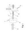
本発明の最適な実施形態によれば、図1に概念的に示されたホール効果センサが開示されており、図1では、アクチュエータ1はセンサ3に電圧5を誘起する磁界を有する磁石4を有する。センサ3は、好ましくは半導体又はシリコンチップ8を有し、しかし、他の型の磁気センサでもよい。本質的にタイヤ圧力6は、ばね力7によって戻り付勢されている磁石4に対抗している。タイヤ圧力6が低すぎるとばね力7が磁石4をホール効果センサから引き離し、かつ磁界2によって発生する電圧5はタイヤ圧力が安全な運転にとって低いと認められる点まで減少する。 According to an optimal embodiment of the present invention, the Hall effect sensor conceptually shown in FIG. 1 is disclosed, in which the actuator 1 includes a magnet 4 having a magnetic field that induces a voltage 5 on the sensor 3. Have. The sensor 3 preferably comprises a semiconductor or silicon chip 8 but may be other types of magnetic sensors. In essence, the tire pressure 6 opposes the magnet 4 which is biased back by the spring force 7. If the tire pressure 6 is too low, the spring force 7 pulls the magnet 4 away from the Hall effect sensor and the voltage 5 generated by the magnetic field 2 decreases to the point where the tire pressure is deemed low for safe driving.
本発明の最も基本的な形態において、本発明には2つの構成要素、即ち、アクチュエータとセンサとがある。アクチュエータはホイールに取り付けられかつホイールと共に回転する。センサは、回転するタイヤのアクチュエータの経路に近接して位置するので、自動車の静止部分、通常は車軸アセンブリに永続的に取り付けられている。アクチュエータはタイヤ圧力に比例した磁気信号を発し、センサは情報を拾いこれを有用な信号に変換しかつその情報をドライバに伝える。 In its most basic form, the present invention has two components: an actuator and a sensor. The actuator is attached to the wheel and rotates with the wheel. Since the sensor is located in close proximity to the path of the rotating tire actuator, it is permanently attached to the stationary part of the automobile, usually the axle assembly. The actuator emits a magnetic signal proportional to the tire pressure, and the sensor picks up the information, converts it into a useful signal and conveys the information to the driver.
好適な実施形態において、タイヤ圧モニタ及び情報伝達器は、自動車の各車軸上の個々のホイールに取り付けられた各タイヤの内部空気圧水準について自動車ドライバに情報を中継する自動車の運転への使用が開示されている。タイヤ圧モニタは自動車のタイヤの内部空気圧に連通する少なくとも1つの回転磁石アクチュエータを有する。この磁気アクチュエータは、内部空気圧に対する磁気アクチュエータのアクセスを図るために、ホイールに対して取り付けられている。取り付けは、ホイールリム、ホイール弁、ホイール側面、ホイール弁軸及びタイヤ自体から成る群から選択された位置にホイールに対して行われる。 In a preferred embodiment, a tire pressure monitor and information transmitter is disclosed for use in driving a vehicle that relays information to the vehicle driver about the internal air pressure level of each tire mounted on an individual wheel on each axle of the vehicle. Has been. The tire pressure monitor has at least one rotating magnet actuator in communication with the internal air pressure of the automobile tire. This magnetic actuator is attached to the wheel in order to allow the magnetic actuator access to the internal air pressure. The attachment is made to the wheel at a position selected from the group consisting of a wheel rim, wheel valve, wheel side, wheel valve stem and tire itself.
空気圧変換器は、車軸と平行に少なくとも1つの回転磁気アクチュエータ内に設けられ、その結果変換器は速度に敏感でなくかつ如何なる速度にも信頼性を有する。空気圧変換器は自動車ドライバにタイヤ圧力情報を伝えるために略1.0psi.から略100pis.の前記内部タイヤ空気圧を検出可能な出力信号に変換することによって、内部タイヤ空気圧に比例する磁束密度を発生する。 The pneumatic transducer is provided in at least one rotating magnetic actuator parallel to the axle so that the transducer is not sensitive to speed and reliable at any speed. The air pressure transducer is approximately 1.0 psi. To convey tire pressure information to the vehicle driver. To approximately 100 psi. The internal tire pressure is converted into a detectable output signal to generate a magnetic flux density proportional to the internal tire pressure.
少なくとも1つの静止磁界センサが回転磁気アクチュエータと対面する関係で永続的に取り付けられており、そこで回転磁気アクチュエータは略0.01mmから略50mm、好ましくは略1mmから2mm回転磁気アクチュエータと磁界センサとの間の物理的距離間隙をおいて回転する。磁界センサは、ホイールが回転をするときには磁界センサの周りを回転して通過する時はいつでも回転磁気アクチュエータによって発生される信号を検出し、かつこの情報をタイヤ圧についての情報を伝達するために発せられる信号に変換する。タイヤ圧力が1(1)以下又は予め設定された安全基準以上のpsi.、好ましくは2(2)以上になった場合にはいつでもタイヤ圧は自動車を運転するための所定の安全基準から越脱する。例えば、タイヤが安全運転のために少なくとも32pis.に高められることが必要であり、通常の高さが36psi.である場合に、タイヤ圧が34psi.以下に低下した場合に、ドライバに警報が送られる。 At least one static magnetic field sensor is permanently attached in a facing relationship with the rotary magnetic actuator, wherein the rotary magnetic actuator is between about 0.01 mm and about 50 mm, preferably between about 1 mm and 2 mm. Rotate with a physical distance between them. The magnetic field sensor detects the signal generated by the rotating magnetic actuator whenever the wheel rotates and passes around the magnetic field sensor and emits this information to convey information about the tire pressure. Is converted into a signal. The tire pressure is 1 (1) or less, or a psi. Whenever it becomes 2 (2) or more, the tire pressure exceeds the predetermined safety standard for driving the automobile. For example, a tire must be at least 32 psi. Normal height is 36 psi. Tire pressure is 34 psi. An alert is sent to the driver when it falls below.
このことは、従来多くの自動車用としてのホール効果センサが知られているが、以下に更に詳細に記載するように、タイヤ圧モニタに関連して種々の実施形態が開示されるようなホール効果センサを利用することは本発明の発明者には知られていなかった。次の実施例は種々のカテゴリーで具体的にされるが、これに限定されない。I.リムマウントメカニカル;II.リムマウント電子圧力センサ;III.弁マウントメカニック及びエレクトロニック;及びIV.弁マウント電子圧力センサ。 This is because many Hall effect sensors for automobiles are known in the past, but as described in more detail below, the Hall effect as disclosed in various embodiments in connection with tire pressure monitors. The use of sensors was not known to the inventors of the present invention. The following examples are embodied in various categories, but are not limited thereto. I. Rim mount mechanical; II. Rimmount electronic pressure sensor; III. Valve mount mechanics and electronic; and IV. Valve mount electronic pressure sensor.
これらの実施形態は、全てホール効果センサを使用するものを順に又は交互に、実用的に利用可能な近接センサ又は磁界誘導センサが開示される。次の実施形態は、互いに対面し、速度に敏感でなくかつ一般的に互いに近接して感知システムが利用され得る限り、これらのセンサのいずれも使用することができる。アクチュエータ内の磁石は、永久強磁性磁石、希土類永久超磁石、電磁石、充電可能な電磁石、コンデンサによって充電可能な電磁石、電子制御可能な電磁石、運転用及び必要な場合に充電する電磁石の組み合わせ及び以上述べた磁石の組み合わせから成る群から選択された少なくとも1つの磁石を利用する。 These embodiments disclose proximity sensors or magnetic field induction sensors that can be used practically, either sequentially or alternately, all using Hall effect sensors. The following embodiments can use any of these sensors as long as the sensing system can be utilized facing each other, not speed sensitive, and generally in close proximity to each other. The magnets in the actuator are permanent ferromagnetic magnets, rare earth permanent supermagnets, electromagnets, rechargeable electromagnets, electromagnets that can be charged by capacitors, electrocontrollable electromagnets, combinations of electromagnets for operation and charging when necessary, and more Utilize at least one magnet selected from the group consisting of the described magnet combinations.
周知のように、2つの磁石が相対的に移動する場合に、電流が発生し、この電流はバッテリーが使用される場合にアクチュエータにおけるバッテリーを充電するために使用されることができる。好ましくはこの電流は自動車に使用される場合に好適なコンデンサに電荷を蓄積するために使用されることができる。バッテリーは、結局消耗するので不適当でありかつ信頼性はこの装置の眼目である。 As is well known, a current is generated when the two magnets move relatively, and this current can be used to charge the battery in the actuator when the battery is used. Preferably this current can be used to store charge in a suitable capacitor when used in an automobile. Batteries are inadequate because they eventually wear out and reliability is the eye of this device.
実施形態は、レーザ、音波(ソナー)、レーダ、光電池、又はホール効果センサ以外の公知のセンサを含む。少なくとも1つの静止磁界センサはホール効果センサ、ピエゾ電気センサ、電子センサ及びこれらの組み合わせから成る群から選択される。
I.リムマウントメカニカル実施形態
リムマウントメカニカル実施形態は、本発明によれば、ホイールのリムを介してアクチュエータを配置して構成され、かつ機械的感知装置を有し、その際小さいピストンがばねによってダイヤフラムに付勢され、かつタイヤの圧力によって反対方向に付勢される。ピストンは、これに接着された磁石を有する。一般的に、タイヤ内からタイヤ内部圧力がある大きさでダイヤフラムを押圧する限り、ばねは自動車ドライバに伝達されることができる信号を供給するために、ホールセンサから所定の空間的関係の下に、ピストンと磁石とを保持する。図2を参照すれば、アクチュエータとセンサの組み合わせは、全体として符号10をつけられ、2つの構成要素を有し、即ち、ホイールに取り付けられてタイヤの回転毎に回転するアクチュエータ11と、自動車、この例では車軸アセンブリ13の回転しない部分に取り付けられるセンサ12とを有する。Embodiments include known sensors other than lasers, sound waves (sonar), radar, photovoltaic cells, or Hall effect sensors. The at least one static magnetic field sensor is selected from the group consisting of a Hall effect sensor, a piezoelectric sensor, an electronic sensor, and combinations thereof.
I. Rim-mount mechanical embodiment The rim-mount mechanical embodiment, according to the invention, comprises an actuator arranged via a wheel rim and has a mechanical sensing device, in which a small piston is brought into the diaphragm by a spring. It is biased and biased in the opposite direction by the tire pressure. The piston has a magnet adhered to it. In general, as long as the pressure inside the tire presses the diaphragm with a certain amount of pressure from within the tire, the spring is subject to a predetermined spatial relationship from the Hall sensor to provide a signal that can be transmitted to the car driver. Hold the piston and magnet. Referring to FIG. 2, the actuator and sensor combination is generally designated 10 and has two components: an actuator 11 mounted on a wheel and rotating with each rotation of the tire, an automobile, This example includes a
磁気アクチュエータの空気圧変換器は、機械的に感知する装置であり、好ましくは磁石に接着されたピストンを係留する弾性部材を有する。この弾性部材は、タイヤ空気圧下に置かれダイヤフラムに取り付けられたばね−ピストンアセンブリである。この弾性部材はコイルばね、圧縮ばね、引張ばね、ゴムプラグ、エラストマー材料、及びダイヤフラムを支持するために適する耐久性(durameter)のある材料の弾性バーから成る群から選択されてもよい。その圧縮強度の理由から選択される発泡ゴム部材は、タイヤ圧力によって付勢されるダイヤフラムに対する設定された抵抗を付与するための最も容易な方法である。 The air pressure transducer of the magnetic actuator is a mechanical sensing device and preferably has an elastic member that anchors a piston bonded to a magnet. The elastic member is a spring-piston assembly that is placed under tire pressure and attached to a diaphragm. The elastic member may be selected from the group consisting of a coil spring, a compression spring, a tension spring, a rubber plug, an elastomeric material, and an elastic bar of a durable material suitable for supporting the diaphragm. Foam rubber members selected for reasons of their compressive strength are the easiest way to impart a set resistance to the diaphragm biased by tire pressure.
基本的には、アクチュエータ11は、自動車のホイールと共に回転し、センサ2はタイヤ圧力について送られてくる信号を拾う。アクチュエータからの信号がない場合、センサ12は、その事実を拾いかつ自動車の計器盤に低圧の信号を中継する。他方、アクチュエータ11がタイヤがフルの圧力又は安全であるとされる圧力を示す信号を出す場合、アクチュエータはタイヤがセンサ12の回りを通過する毎にその信号を中継し、センサ12は計器盤の指示器の光に対して反応しない。磁気アクチュエータの空気圧変換器中に装着される磁石は、信号をカットするために静止のセンサから、略5mmから略15mm,12.7mmのオーダで移動することのみが必要であり、それによって自動車のドライバにその情報の伝達を行う。実際に、ホイールの製造の実用的な公差は、隙間距離に対して±0.010mmである。この公差によってタイヤが回転し又はスペアが装着される場合の低圧設定点における最大の差は±0.4psi.である。 Basically, the
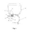
充分な理解のために図2と図3とを参照すれば、図2はホイールとタイヤが取り付けられた自動車に関連したアクチュエータ11とセンサ12の相対的な配置を示す。図3は本発明により構成されたホール効果アクチュエータの拡大横断面図を表す。本発明の第1実施形態において、構成要素の全ては機械的性質を有するが、以下電気・機械及び電子的実施形態を有する実施形態を示す。 2 and 3 for full understanding, FIG. 2 shows the relative placement of
図2を参照すれば、アクチュエータ11が自動車ホイール15のリム16にねじ止めされている。タイヤ14はリムに嵌められている。ホイール15は取り付け面17上の自動車車軸(図示しない)上に取り付けられている。ホイールの製造に使用される自動車の実用上の公差は、非常に狭く、アクチュエータ11のセンターライン18と取り付け面17の後側との間の距離19について、±0.010インチのオーダである。この公差が製造上狭くされかつ工業界において標準とされるので、本発明は、センサ12とアクチュエータ11の間の隙間20の特定のための公差に依存する。タイヤにおける1psi.の圧力変化に対して、ピストンは略0.025インチ(0.625mm)移動する。 Referring to FIG. 2, the
ホール効果センサに普通に使用される場合、隙間20は所定の値に維持され、タイヤホイール15が後側で洗浄されかつ自動車の車軸と適当に組み合わされる場合にホイールとしての実用的公差を保持する。 When normally used for Hall effect sensors, the
図2と図3とを参照すれば、標準的なホール効果センサが認められることができ、これは通常スイス国チューリッヒのマイクロナスセミコンダクタ、オハイオ州のウエスタービレッジのレークショアクライオトロニック会社、及びフロリダ州のオーランドのサイプライス会社から利用可能であり、車軸アセンブリ13は、略0.01mmから略50mmまでの所定の距離、好ましくは1mmから10mmのオーダで、最も好ましくは1mmから略3mmだけ離れて位置する。 With reference to FIGS. 2 and 3, a standard Hall effect sensor can be recognized, which is typically Micronas Semiconductor in Zurich, Switzerland, Lakeshore Cryotronic Company in Wester Village, Ohio, and Florida. The
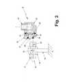
図3は本発明のタイヤ圧力センサ10の拡大図であり、かつホイールに永続的に取り付けられるアクチュエータ11と車軸アセンブリ13のような自動車に永続的に取り付けられる静止磁界センサ12とを示す。アクチュエータ11は例えば、ホイールリムを通って延びるパイプニップルねじ22によってホイールに取り付けられ、かつタイヤの内部空気圧がハウジング21によって特定されるキャビテー内に開口する。ダイヤフラム23はタイヤ内部からの空気圧を受けかつピストン26に押圧する。 FIG. 3 is an enlarged view of the
ピストン26は磁石27に接着され、かつ両者はその位置にハウジング端25によって保持される。リテーナ24、道路破片、グリース及び埃がばね中の磁石との接触を阻止するために、その一体的な非常に薄い端部材28によって所定に位置に端部ハウジングを保持する。部材28は好ましくは略0.5mmから略5mmまでの厚さを有する。
従って、タイヤ内からの空気圧はダイヤフラムを押し、ダイヤフラムはピストン26を押し、その結果磁石27を非常に薄い端部材28に対抗する位置に付勢する。タイヤからの空気圧が低すぎると、ばね29はピストン26をハウジング21によって形成されたキャビテー中に押し込み、それによって磁石27は非常に薄い端部材28から押し離され、それによって磁界センサ12によって感知され得る磁界密度を減少させる。磁界センサ12は車軸アセンブリ13に永続的に取り付けられ、かつブラケット又はキー32によって所定の位置に保持されかつピン33によって回転安定に保持される。ジャムナット34は、センサ12を所定に位置に保持し、一方コネクター31は電気的であれ、どうであれ情報を自動車ドライバに中継するために使用される。 Thus, the air pressure from within the tire pushes the diaphragm, which pushes the
始めに自動車ドライバが安全ではない道路タイヤ圧力状態を表示する計器盤表示器を有することが想定されるが、本発明によれば、タイヤ圧力が低い、又は多分ハンドルの振動又は自動車の注意を引く他の信号を自動車ドライバに知らせる音響装置を含む何らかの中継方法が利用されることが想定される。新しい自動車はウインドガラスにホログラフによる像を形成するので、そのような情報部分がそのような方法で自動車ドライバに送られることができるか、又はバックミラーに表示される。どのようにして情報が送られるにしても、コネクタ31は直接自動車のECUに接続し、又は搭載コンピュ−タから分離して計器盤表示器に電子信号を伝達する別個のケーブルである。これら全ての方法は本発明によって想定されるが、自動車ドライバにタイヤセンサについての情報を伝達するための最も適切な手段を決定するのは当業者に委ねられている。 Initially it is envisaged that the car driver will have an instrument panel indicator to indicate unsafe road tire pressure conditions, but according to the present invention, the tire pressure is low, or possibly steering wheel vibration or car attention It is envisaged that some relay method including an audio device that informs the car driver of other signals is used. Since new cars form holographic images on the windshield, such information parts can be sent in such a way to the car driver or displayed in the rearview mirror. Regardless of how the information is sent,
図4を参照すれば、図2及び図3とは僅かに異なる本発明の実施形態が示されるが、ピストン26の相異なる構成内に取り付けられたばね29の間の円筒状磁石を有する音波溶接されたプラスチック構造物を含む。以上に開示したように、永久磁石はこの作業には適するが、センサに対して較正されかつアクチュエータとセンサとの間の適切な隙間距離が設定される場合、いかなる型の磁石も使用される。再び図3において、タイヤ内からの空気圧はアクチュエータのトップから下方に進みかつダイヤフラム23に直接隣接した室に入る。好ましくは実施形態において、ハウジング25は一体の部材であり、かつ別個の係留部材及び端部ハウジングから成るものではない。図3は、ドーナツ形の磁石を示し、そこには図4と同様にバー又は円筒状の磁石を示す。
II.リムマウント電子圧力センサ
本発明の更に別の実施形態によれば、図5はリムマウント電子圧力センサを示し、図2〜4に示す永久磁石に代わるものを除いては、図2〜4に表すと同一の原理を有し、図5の実施形態は、電磁コイル28をチャージするために使用されるバッテリー、充電可能なバッテリー又はコンデンサを含む電源27によって駆動される電磁コイル28を表す。再び図5は符号11で表されるアクチュエータの間の伝達を示し、かつその個所にホイールリム16を介して内部空気圧に接続される。アクチュエータ12は車軸アセンブリ13に永続的に取り付けられており、かつアクチュエータ11とセンサ12との間に物理的距離隙間20を有する。アクチュエータ11のセンターライン18は、ホイール15の後部取り付け板17から距離19に維持される。タイヤ14はホイールリム16とアクチュエータ11を介して圧力を受け、かつ電磁コイル28を介して供給される電気量によって磁界の特別な値を電磁石に持たせる。Referring to FIG. 4, an embodiment of the present invention that is slightly different from that of FIGS. 2 and 3 is shown, but is sonic welded with a cylindrical magnet between
II. Rim Mount Electronic Pressure Sensor According to yet another embodiment of the present invention, FIG. 5 shows a rim mount electronic pressure sensor and is shown in FIGS. 2-4 except that it replaces the permanent magnet shown in FIGS. The embodiment of FIG. 5 represents an
拡大図である図6をも参照すれば、電子ボード26は圧力センサとして作用し、かつピエゾ電気変換器のようなソリッドステート圧力センサであることが分かる。空気圧は、パイプニップル22を介してホイールリムに取り付けられたハウジング21を介して低下する。この実施形態において、圧力センサ26は電子ボード、好ましくはピエゾ電気又はソリッドステートであり、かつ電磁コイル28に供給される電気量を順次指示する電源27に路線29を介して信号を送るために増幅器を有する。 Referring also to FIG. 6, which is an enlarged view, it can be seen that the
本発明の他の実施形態において、少なくとも1つの電磁コイル28があり、そこでは第1コイル28は隙間22を横切るアクチュエータ11によって送られる磁界を発生させるために使用され、かつ第2コイルは必要な場合にバッテリーを充電するか又はコンデンサ27を充電するために使用される。アクチュエータに取り付けられた電気回路が周知であり、この電気回路は回転する磁石28と接触する場合に、バッテリー27を充電するか又はコンデンサ27に電荷を蓄えるバックアップ電圧を生成するために、電気を発生する。上記の機械的な実施形態と同様に、アクチュエータ12はピン33によって保持されるキー32によって自動車、例えば、車軸アセンブリ13に永続的に取り付けられている。ジャムナット34はアクチュエータをその位置に保持し、かつ上記のようにバックアップ電圧を誘導するために永久磁石又は電磁石の任意の磁石30を含む。更に、電気コネクタ31は上記の方法のいずれかで自動車ドライバに情報を伝達するために使用される。いかなる電力供給も経済的でありかつ信頼性がありかつ電磁コイル28に常に電気を供給できるものはこの実施形態への使用に適する。 In another embodiment of the invention, there is at least one
アクチュエータ11は、好ましくはインジェクション成形されたプラスチックから作られるが、アルミニウムブロックから切削され又はゴム被覆モールドされてもよい。道路破片、汚れ及び塵埃を構成要素から除去するために、種々の構成要素が周囲から隔離されることが必要である。 The
更に、好ましくは実施形態においては、アクチュエータ11が「スマート」なアクチュエータであり、センサ12が「スマート」なセンサでる。電子技術分野の当業者は、この適用のために何が最も経済的にかつ信頼性をもって実施できるかを決定することができる。換言すれば、アクチュエータは、タイヤ圧モニタシステムの「スマート」な端末であり、情報の変化の程度は電磁コイル28によって経験された電磁気の領域によって決定されることができる。他方では、半導体又はシリコンチップを使用するセンサ12はタイヤ圧モニタの「スマート」な端末である。
III.弁マウントメカニカル及びエレクトロ二カル
図7は、本発明による弁マウントバージョンを表し、その際弁にセンサが取り付けられ、かつ現在実用的に利用可能なホイールに既に使用されている弁軸孔を介してタイヤ圧力と通じている。アクチュエータ11はタイヤ中に空気圧を再度充填するために使用される弁軸の延長部と一体である。アクチュエータは自動車のセンタから外方に移動されるので、センサ12とアクチュエータ11との間の隙間を有効な物理的距離だけ離すことを可能にするために、センサ12はブラケット14によって車軸アセンブリ13から延ばされることが必要である。云うまでもないことであるが、これまでに記載した実施形態と同一の隙間がこの実施形態においても必要である。Further, in the preferred embodiment, the
III. FIG. 7 represents a valve mount version according to the invention, via a valve shaft hole in which a sensor is attached to the valve and is already used in wheels that are currently practically available. It communicates with tire pressure.
ホイール15を通って延びる弁軸孔16によってホイール15に取り付けられたタイヤ14が示され、その結果弁軸17はアクチュエータが取り付けられてもタイヤ圧力を再度充填するためにアクセスされ得る。ホイール15は標準のホイールであり、本発明によるタイヤ圧モニタは弁軸孔16を通って端に挿入されることができかつこの孔を通って延びる弁軸17を有することによって作動を継続されることができる。ブラケット14は、アクチュエータ11の近くにセンサ12を延ばすために必要な他の追加部材である。ブラケット14はアクチュエータ11の直ぐ近くの位置にセンサ12を位置させるために適当な構成であればよい。図8を参照すれば、弁アクチュエータハウジング21がその先端に弁プラグ22を有する弁マウントメカニカル実施形態である。弁軸17は、ハウジング21を通して受けた空気圧と直接関連している。端部ハウジング25は、磁石27の周囲部分を形成する非常に薄い部分28とピストン26内に保持されたばね29とを有する。この実施形態はこれまでに記載したものと非常に類似しているが、空気室24を除いて、弁軸孔を介してタイヤの内部タイヤ空気圧と関連している。 The
IV.弁マウント電子圧力センサ
図9は、タイヤ14が取り付けられた後に弁軸孔16におけるホイール15の弁軸開口を通る電子センサの相対的位置を示す。弁軸17はアクチュエータ11とセンサ12との間の物理的距離隙間20を保持しつつタイヤを再度充填するために、自動車ドライバになお利用可能である。センサ12は自動車の車軸アセンブリ13に永続的に取り付けられているブラケット14上に取り付けられる。IV. Valve Mount Electronic Pressure Sensor FIG. 9 shows the relative position of the electronic sensor through the valve shaft opening of the
図10を参照すれば、符号11で示す弁マウント電子圧力センサの横断面図が示されている。さらに、電子バージョンのアクチュエータ11は、被覆線29を介して電子センサ26からの情報を受ける電磁コイル28と関連した電源27を有する。ハウジング21は、ホイール15の孔16を介してタイヤ内部圧力と関連した空気室23のための凹部を有する。空気室31はアクチュエータハウジング21によって区画されており、かつホイールブラケット30を介してジャムナット32によって所定に位置に保持される。外部要素は、湾曲部、好ましくはOリング33によって保持され、Oリングは道路破片、埃及び汚れから空気圧室34をクリーンにしかつ影響受けないように保持する。弁軸17はタイヤ圧力が低下した場合に、タイヤを再度充填するために、ホイールの外部から自動車ドライバにアクセスできるように開いている。 Referring to FIG. 10, a cross-sectional view of the valve mount electronic pressure sensor indicated by 11 is shown. Further, the electronic version of the
本発明の使用方法は、次のように要約される;即ち、タイヤ内部空気圧と連通するために自動車のホイールを介して少なくとも1つの磁気アクチュエータを取り付け、その結果少なくとも1つのアクチュエータの磁石は自動車のセンタに面し、その結果磁気アクチュエータのアクチブ部分は、速度感度を最少にするためにホイールの車軸に実質的に平行に位置する。自動車に少なくとも1つの静止磁界センサが永続的に取り付けられ、それによって磁界センサはアクチュエータとセンサとの間の略0.01mmから略50mmの間の物理的距離隙間を有する少なくとも1つの磁気アクチュエータと対面しており、その結果磁界センサは磁気アクチュエータの磁界の磁力線内に位置決めされることができ、それによって信号が発生される。これは自動車の安全運転に関して自動車ドライバにタイヤ内部空気圧に比例する信号を伝達するように案内する。 The method of use of the present invention can be summarized as follows: at least one magnetic actuator is mounted via the vehicle wheel to communicate with the tire internal air pressure so that the magnet of the at least one actuator is Facing the center, the active part of the magnetic actuator is thus located substantially parallel to the wheel axle to minimize speed sensitivity. At least one static magnetic field sensor is permanently attached to the vehicle so that the magnetic field sensor faces at least one magnetic actuator having a physical distance gap between approximately 0.01 mm and approximately 50 mm between the actuators. As a result, the magnetic field sensor can be positioned within the magnetic field lines of the magnetic actuator's magnetic field, thereby generating a signal. This guides the vehicle driver to transmit a signal proportional to the tire internal pressure for safe driving of the vehicle.
要約すれば、上記の実施形態は全て、低いタイヤ圧力を検出するための自動車工業によって期待される利点と対象を提供する。本発明の好適な実施形態のこれまでの記載は、図示及び記載のために行われた。除外したり又は開示された形態に本発明を限定するものではない。特別な実施形態についての上記の教示の下に明らかな変形又はバリエーションが可能である。これらの実施形態は、本発明の原理及び種々の実施形態でかつ意図される使用目的に適する種々の変形によって当業者に本発明の利用を可能にする実際の適用を最適に表すために選択されかつ記載されている。特許請求の範囲によって特定された本発明の範囲が保護されることを意図している。 In summary, all of the above embodiments provide the benefits and objects expected by the automotive industry to detect low tire pressures. The foregoing description of preferred embodiments of the present invention has been presented for purposes of illustration and description. It is not intended to be exhaustive or to limit the invention to the forms disclosed. Obvious variations or variations are possible under the above teachings of particular embodiments. These embodiments are selected to optimally represent the actual application that will enable one of ordinary skill in the art to make use of the invention by virtue of the principles of the invention and the various embodiments and variations that are suitable for the intended use. And are described. It is intended that the scope of the invention specified by the claims be protected.
本発明によるタイヤ圧モニタは乗客及び荷物を搭載する全ての自動車に有利に利用されることができる。 The tire pressure monitor according to the present invention can be advantageously used in all automobiles carrying passengers and luggage.
1 アクチュエータ
2 磁界
3 ホール効果センサ
4 磁石
5 電圧
6 タイヤ圧力
7 ばね力
8 半導体又はシリコンチップ
10 圧力センサ
11 アクチュエータ
12 センサ
13 車軸アセンブリ
14 タイヤ
15 ホイール
16 リム
17 取付面
18 センターライン
19 距離
20 隙間
21 ハウジング
22 ねじ
23 ダイヤフラム
24 リテーナ
26 ピストン
27 磁石
28 非常に薄い端部材
29 ばね
32 キー溝
33 ピン
34 ジャムナットDESCRIPTION OF SYMBOLS 1 Actuator 2 Magnetic field 3 Hall effect sensor 4 Magnet 5 Voltage 6 Tire pressure 7 Spring force 8 Semiconductor or
14
Claims (17)
Translated fromJapanese少なくとも1つの回転磁気アクチュエータと、
空気圧変換器と、
少なくとも1つの静止磁界センサと、
信号発生器とから成り、
回転磁気アクチュエータは、自動車のタイヤのタイヤ内部空気圧と連通しており、この磁気アクチュエータはタイヤ内部空気圧に対する磁界アクチュエータのアクセスを図るためにホイールに対して取り付けられており、この取り付けはホイールリム、ホイール弁、ホイール側面、ホイール弁軸及びタイヤ自体から成る群から選択された位置にホイールに対して行われ、
空気圧変換器はホイールに対して取り付けられた少なくとも1つの回転磁気アクチュエータ内にあって車軸と平行になっており、その結果変換器は速度に敏感でなくかついかなる速度でも信頼性を有し、自動車ドライバに対するタイヤ圧力情報を伝達するための検出可能な出力信号に、略1.0psi.から略100psi.のタイヤ内部空気圧の入力信号を変換することによって前記タイヤ内部空気圧に比例する信号を発生させるための前記空気圧変換器が使用され、
静止磁界センサは回転磁気アクチュエータに対面して永続的に取り付けられており、このセンサは回転磁気アクチュエータと磁界センサとの間に略0.01mmから略50mmの間の物理的隙間をおいて回転するときに回転磁気アクチュエータと対面するように自動車の静止部分に永続的に取り付けられており、それによって磁界センサはホイールが回転して磁界センサを通り過ぎる毎に回転磁気アクチュエータによって発生される信号を検出し、
前記信号発生器はタイヤ圧力が自動車の運転のための所定の安全な水準から外れるときはいつでもタイヤ空気圧を中継するために自動車ドライバに信号情報を伝達するために静止磁界センサと連通していることを特徴とする前記タイヤ圧モニタ又は情報伝達器。In a tire pressure monitor or information transmitter used in driving a car to relay information to the car driver about the tire internal air pressure level of each tire mounted on an individual wheel of each car axle,
At least one rotary magnetic actuator;
An air pressure transducer,
At least one static magnetic field sensor;
Consisting of a signal generator,
The rotating magnetic actuator is in communication with the tire internal air pressure of the automobile tire, and this magnetic actuator is attached to the wheel to provide access to the magnetic field actuator for the tire internal air pressure. Performed on the wheel at a position selected from the group consisting of a valve, a wheel side, a wheel valve stem and the tire itself;
The pneumatic transducer is in at least one rotating magnetic actuator mounted to the wheel and parallel to the axle so that the transducer is not speed sensitive and is reliable at any speed, The detectable output signal for transmitting tire pressure information to the driver is approximately 1.0 psi. To approximately 100 psi. The pressure transducer is used to generate a signal proportional to the tire internal pressure by converting an input signal of the tire internal pressure of
The static magnetic field sensor is permanently mounted facing the rotary magnetic actuator, and the sensor rotates with a physical gap between about 0.01 mm and about 50 mm between the rotary magnetic actuator and the magnetic field sensor. Sometimes it is permanently attached to the stationary part of the car to face the rotating magnetic actuator, so that the magnetic field sensor detects the signal generated by the rotating magnetic actuator each time the wheel rotates and passes the magnetic field sensor ,
The signal generator is in communication with a static magnetic field sensor to communicate signal information to the vehicle driver to relay tire pressure whenever the tire pressure deviates from a predetermined safe level for driving the vehicle. The tire pressure monitor or the information transmitter.
回転磁気アクチュエータと、
空気圧変換器と、
静止磁界センサと、
信号発生器とからなり、
回転磁気アクチュエータは、自動車のタイヤのタイヤ内部空気圧と常に連通し、この磁気アクチュエータはタイヤ内部空気圧にアクチュエータを接近させるためにホイールに対して取り付けられており,この取り付けはホイールリム、ホイール弁、ホイール側面、ホイール弁軸から成る群から選択された位置にホイールに対して行われ、
空気圧変換器は回転磁界アクチュエータ内にあって、略1.0psi.から略100psi.のタイヤ内部空気圧の入力信号を略1mksから略10000000mksの磁束密度の出力信号に変換することによってタイヤ内部空気圧に比例する磁束密度を発生し、
静止磁界センサは、運転中回転磁界アクチュエータが取り付けられているホイールが自動車の車軸の回りを回転する時に回転磁気アクチュエータから略0.01mmから略50mmの物理的隙間をもって自動車に永続的に取り付けられており、それによって磁界センサはホイールと共に回転する毎に回転磁気アクチュエータによって発生する磁界密度を検出し、
信号送信器は静止磁界センサと連通していて、タイヤ圧力が自動車運転に安全なタイヤ空気圧よりも略1psi.から略5psi.高い値よりも低い水準に低下した場合に低タイヤ空気圧情報を中継するために自動車ドライバに情報を伝達するために信号を送信することを特徴とする前記タイヤ圧モニタ又は情報伝達器。In a tire pressure monitor or information transmitter used in driving a car to relay information to the car driver about the tire internal air pressure level of each tire mounted on an individual wheel of each car axle,
A rotating magnetic actuator;
An air pressure transducer,
A static magnetic field sensor;
A signal generator,
The rotating magnetic actuator is always in communication with the tire internal air pressure of the car tire, and this magnetic actuator is attached to the wheel to bring the actuator close to the tire internal air pressure, which is attached to the wheel rim, wheel valve, wheel Performed on the wheel at a position selected from the group consisting of side, wheel valve stem,
The pneumatic transducer is in the rotating field actuator and is approximately 1.0 psi. To approximately 100 psi. A magnetic flux density proportional to the tire internal air pressure is generated by converting the input signal of the tire internal air pressure into an output signal having a magnetic flux density of about 1 mks to about 10000000 mks,
The static magnetic field sensor is permanently attached to the automobile with a physical clearance of about 0.01 mm to about 50 mm from the rotating magnetic actuator when the wheel to which the rotating magnetic field actuator is attached rotates around the axle of the automobile during operation. The magnetic field sensor detects the magnetic field density generated by the rotating magnetic actuator each time it rotates with the wheel,
The signal transmitter is in communication with the static magnetic field sensor, and the tire pressure is approximately 1 psi. To approximately 5 psi. A tire pressure monitor or information transmitter as set forth in claim 1 wherein a signal is transmitted to convey information to an automobile driver to relay low tire pressure information when the level drops below a high value.
自動車に少なくとも1つの静止磁界センサを永続的に取り付け、それによって磁界センサはアクチュエータとセンサとの間に略0.01mmから略50mmの物理的隙間で対面し、その結果磁界センサは磁気アクチュエータの磁界の磁力線内に位置づけられ、それによって信号が発生し、
自動車の安全運転に関してタイヤ内部空気圧に比例する信号を伝達することを特徴とする請求項1に記載にタイヤ圧モニタの使用方法。At least one magnetic actuator is mounted on the vehicle wheel to communicate with the tire internal pressure so that the at least one actuator faces the vehicle center and the active portion of the magnetic actuator minimizes speed sensitivity Located substantially parallel to the wheel axle,
At least one static magnetic field sensor is permanently attached to the vehicle so that the magnetic field sensor faces with a physical gap of approximately 0.01 mm to approximately 50 mm between the actuators, so that the magnetic field sensor is the magnetic field of the magnetic actuator. Is located within the magnetic field lines, thereby generating a signal,
2. The method of using a tire pressure monitor according to claim 1, wherein a signal proportional to tire internal air pressure is transmitted for safe driving of an automobile.
Applications Claiming Priority (6)
| Application Number | Priority Date | Filing Date | Title |
|---|---|---|---|
| US44808503P | 2003-02-15 | 2003-02-15 | |
| US44808803P | 2003-02-15 | 2003-02-15 | |
| US47061203P | 2003-05-16 | 2003-05-16 | |
| US49406503P | 2003-08-08 | 2003-08-08 | |
| US49406603P | 2003-08-08 | 2003-08-08 | |
| PCT/US2004/004739WO2004074013A2 (en) | 2003-02-15 | 2004-02-17 | Tire pressure monitoring system and method of using same |
Publications (1)
| Publication Number | Publication Date |
|---|---|
| JP2006518307Atrue JP2006518307A (en) | 2006-08-10 |
Family
ID=32913322
Family Applications (1)
| Application Number | Title | Priority Date | Filing Date |
|---|---|---|---|
| JP2006503663APendingJP2006518307A (en) | 2003-02-15 | 2004-02-17 | Tire pressure monitor and its use |
Country Status (6)
| Country | Link |
|---|---|
| US (1) | US7032443B2 (en) |
| EP (1) | EP1599350A4 (en) |
| JP (1) | JP2006518307A (en) |
| CA (1) | CA2515769A1 (en) |
| MX (1) | MXPA05008640A (en) |
| WO (1) | WO2004074013A2 (en) |
Families Citing this family (29)
| Publication number | Priority date | Publication date | Assignee | Title |
|---|---|---|---|---|
| US7379800B2 (en)* | 2000-09-08 | 2008-05-27 | Automotive Technologies International, Inc. | Tire pressure monitoring using hall effect sensors |
| US9443358B2 (en) | 1995-06-07 | 2016-09-13 | Automotive Vehicular Sciences LLC | Vehicle software upgrade techniques |
| US10240935B2 (en) | 1998-10-22 | 2019-03-26 | American Vehicular Sciences Llc | Vehicle software upgrade techniques |
| CN100354149C (en)* | 2004-09-24 | 2007-12-12 | 重庆三信电子有限公司 | Radar monitoring displaying alarming system of automobile tyre pressure, back car |
| USD517976S1 (en)* | 2004-10-08 | 2006-03-28 | Nokian Tyres Plc | Tire |
| JP4289561B2 (en)* | 2004-12-24 | 2009-07-01 | 横浜ゴム株式会社 | Vehicle abnormality detection method and apparatus, and sensor unit thereof |
| MX2007009640A (en)* | 2005-02-11 | 2007-09-25 | Massachusetts Inst Technology | Surface injection device. |
| US7833189B2 (en) | 2005-02-11 | 2010-11-16 | Massachusetts Institute Of Technology | Controlled needle-free transport |
| US7490700B2 (en)* | 2005-06-02 | 2009-02-17 | Shimano Inc. | Bicycle motion sensing arrangement |
| JP4490342B2 (en)* | 2005-07-08 | 2010-06-23 | 住友ゴム工業株式会社 | Tire pressure drop detection method and apparatus, and tire decompression determination program |
| EP1984216A2 (en)* | 2005-12-15 | 2008-10-29 | THE GOODYEAR TIRE & RUBBER COMPANY | A method of determining vehicle properties |
| BRPI0716071A2 (en)* | 2006-09-01 | 2013-09-24 | Massachusetts Inst Technology | NEEDLE-FREE TRANSMEDIATE TRANSPORT DEVICES AND METHODS FOR TRANSFERING A SUBSTANCE THROUGH A BODY SURFACE |
| US7804396B2 (en)* | 2007-09-21 | 2010-09-28 | Advanced Tire Pressure Systems, Inc. | Tire pressure monitoring system having a collapsible casing |
| KR100951988B1 (en)* | 2007-12-15 | 2010-04-08 | 현대자동차주식회사 | Vehicle tire pressure supplement system and control method |
| DE102008040682A1 (en)* | 2008-07-24 | 2010-01-28 | Robert Bosch Gmbh | Sensor arrangement and method for operating a sensor arrangement |
| DE102008054161A1 (en)* | 2008-10-31 | 2010-05-06 | Knorr-Bremse Systeme für Nutzfahrzeuge GmbH | Tire pressure monitoring device with magnetic induction power supply |
| WO2011028719A2 (en) | 2009-09-01 | 2011-03-10 | Massachusetts Institute Of Technology | Nonlinear system identification techniques and devices for discovering dynamic and static tissue properties |
| US9333060B2 (en) | 2009-12-15 | 2016-05-10 | Massachusetts Institute Of Technology | Plaque removal and differentiation of tooth and gum |
| DE102009058881A1 (en)* | 2009-12-18 | 2011-06-22 | Continental Automotive GmbH, 30165 | Filling and filling assistant |
| US9120357B2 (en)* | 2013-03-15 | 2015-09-01 | Continental Automotive Systems, Inc. | Methods, systems and devices for integration of tire pressure monitoring sensors with a tire pressure monitoring system |
| US20150336435A1 (en)* | 2014-05-24 | 2015-11-26 | Rimex Supply Ltd. | Magnetic mount for tire pressure sensor |
| US9522577B2 (en)* | 2014-08-19 | 2016-12-20 | Hyundai America Technical Center, Inc | Dynamic tire air pressure system |
| US10308352B2 (en)* | 2014-12-12 | 2019-06-04 | Borealis Technical Limited | Monitoring system for aircraft drive wheel system |
| EP3390029B1 (en) | 2015-12-16 | 2020-09-09 | Bridgestone Americas Tire Operations, LLC | Magnetic tire sealant for puncture detection |
| US10792961B2 (en) | 2016-06-23 | 2020-10-06 | Pacific Industrial Co., Ltd. | Tire state monitoring device |
| FR3066722B1 (en)* | 2017-05-23 | 2019-06-07 | Continental Automotive France | METHOD FOR DETERMINING THE SET-UP OF A MOTOR VEHICLE EQUIPPED WITH A SYSTEM FOR MONITORING THE PRESSURE OF A TIRE |
| EP3583892A1 (en)* | 2018-06-20 | 2019-12-25 | Koninklijke Philips N.V. | Pressure sensing unit, system and method for remote pressure sensing |
| CN112504698A (en)* | 2020-10-29 | 2021-03-16 | 重庆交通职业学院 | A compressive strength detection device for automobile tire production |
| CN119534909B (en)* | 2025-01-20 | 2025-03-28 | 杭州临安天隆电子有限公司 | High-precision wheel speed sensor |
Citations (9)
| Publication number | Priority date | Publication date | Assignee | Title |
|---|---|---|---|---|
| JPS51151168A (en)* | 1975-06-09 | 1976-12-25 | Scovill Manufacturing Co | Apparatus for sensing and indicating vehicle tire air pressure |
| JPH0243705U (en)* | 1988-09-21 | 1990-03-26 | ||
| US4953394A (en)* | 1987-10-08 | 1990-09-04 | Alligator Ventilfabrik Gmbh | Device and process for controlling air pressure in tires |
| DE4108337C1 (en)* | 1991-03-14 | 1992-07-30 | Doduco Gmbh + Co Dr. Eugen Duerrwaechter, 7530 Pforzheim, De | |
| JPH06293205A (en)* | 1993-01-21 | 1994-10-21 | Nippondenso Co Ltd | Tire pneumatic pressure detecting device |
| JPH0769014A (en)* | 1993-08-31 | 1995-03-14 | Nhk Spring Co Ltd | Tire pneumatic pressure monitor device |
| JPH07167726A (en)* | 1993-09-01 | 1995-07-04 | Telesignal Srl | Tire pressure monitoring system for a car while driving |
| JPH07172120A (en)* | 1993-12-22 | 1995-07-11 | Fujikura Ltd | Tire pressure detection device |
| JPH07323709A (en)* | 1994-05-31 | 1995-12-12 | Fujikura Ltd | Tire pressure detection device |
Family Cites Families (42)
| Publication number | Priority date | Publication date | Assignee | Title |
|---|---|---|---|---|
| US1683343A (en)* | 1928-09-04 | Liam shacexeton | ||
| US2229192A (en)* | 1939-07-15 | 1941-01-21 | Schultz Laurance | Tire inflation indicator |
| US2629086A (en)* | 1950-07-21 | 1953-02-17 | Ainsworth | Tire pressure responsive safety device |
| US3521230A (en)* | 1967-11-07 | 1970-07-21 | Ford Motor Co | Low tire pressure sensing mechanism |
| US3588814A (en)* | 1968-03-11 | 1971-06-28 | Thad E Furlong | Electric tire inflation indicator |
| NL134984C (en)* | 1968-07-29 | |||
| US3715719A (en)* | 1970-03-03 | 1973-02-06 | U Sugiyama | Tire pressure indication system |
| DE7107228U (en)* | 1970-03-03 | 1972-03-02 | Sugiyama, Uichiro, Tokio | TIRE PRESSURE DISPLAY DEVICE |
| JPS519637B1 (en)* | 1971-06-17 | 1976-03-29 | ||
| JPS5125354B2 (en)* | 1971-12-27 | 1976-07-30 | ||
| US3777565A (en)* | 1972-08-03 | 1973-12-11 | Gamon Calmet Ind Inc | Magnetic converter for water meters |
| JPS49108476U (en)* | 1973-01-10 | 1974-09-17 | ||
| GB1459151A (en)* | 1974-03-05 | 1976-12-22 | Kanto Seiki Co | Tyre pressure alarm equipment |
| IT1012728B (en)* | 1974-05-22 | 1977-03-10 | Mecanique Ind Int | DEVICE FOR REMOTE TRANSMIT OF PRESSURE SIGNALS |
| GB1594612A (en)* | 1977-01-19 | 1981-08-05 | Dunlop Ltd | Tyre deflation warning apparatus |
| US4131877A (en)* | 1977-06-24 | 1978-12-26 | General Motors Corporation | Low tire pressure indicator circuit |
| US4119944A (en)* | 1977-06-27 | 1978-10-10 | Jesse Britton Smith | Vehicular tire air pressure measuring system |
| IT1101174B (en)* | 1978-12-04 | 1985-09-28 | Rigazio E | DEVICE FOR THE DETECTION OF THE TIRE PRESSURE OF A VEHICLE |
| US4339955A (en)* | 1980-08-29 | 1982-07-20 | Aisin Seiki Company, Ltd. | Pressure sensor |
| US4570152A (en)* | 1984-04-23 | 1986-02-11 | Hyperion Corporation | Magnetic tire monitor system |
| US4627292A (en)* | 1984-07-03 | 1986-12-09 | Randek Inc. | AC transducers, methods and systems |
| JPS61232906A (en) | 1985-04-10 | 1986-10-17 | Japan Electronic Control Syst Co Ltd | Monitor device for air-pressure of vehicle tire |
| US4742857A (en)* | 1986-10-07 | 1988-05-10 | Techni Guidance, Inc. | Tire pressure sensor and air supply to maintain desired tire pressure |
| DE3720373C1 (en) | 1987-06-19 | 1988-05-26 | Bochumer Eisen Heintzmann | Pressure transducer |
| US4966034A (en)* | 1988-04-28 | 1990-10-30 | Schrader Automotive, Inc. | On-board tire pressure indicating system performing temperature-compensated pressure measurement, and pressure measurement circuitry thereof |
| US4846886A (en)* | 1988-05-05 | 1989-07-11 | Dow Corning Corporation | Water beading-water shedding repellent composition |
| US4866982A (en)* | 1988-08-22 | 1989-09-19 | Telemagnetics, Inc. | On-board tire pressure sensing system |
| FR2670889B1 (en)* | 1990-11-30 | 1995-05-24 | Skf France | ENGLISH RACKED WOODEN STAIRCASES, POSTS, RAILS, SIMPLIFIED MANUFACTURING AND LAYING GUARDS. |
| US5717135A (en)* | 1991-09-30 | 1998-02-10 | Carl A. Fiorletta | Tire pressure monitoring system utilizing a pressure activated transducer and sensor |
| US6662642B2 (en)* | 2000-09-08 | 2003-12-16 | Automotive Technologies International, Inc. | Vehicle wireless sensing and communication system |
| JPH06247112A (en)* | 1993-02-24 | 1994-09-06 | Nhk Spring Co Ltd | Pressure detecting device and tire air pressure detecting device |
| DE69400987T2 (en)* | 1993-08-31 | 1997-03-27 | Nhk Spring Co Ltd | Tire pressure monitoring device |
| GB2284918B (en)* | 1993-12-17 | 1997-05-21 | Fuji Heavy Ind Ltd | Inflation pressure sensor for automobile pneumatic tyre |
| CA2168940C (en)* | 1995-02-08 | 2007-05-01 | Kenji Furuichi | Tire pressure detector |
| US5764137A (en)* | 1996-12-09 | 1998-06-09 | Chrysler Corporation | System and method for diagnosing loss of pressure in tires of a vehicle |
| US6230556B1 (en)* | 1998-11-04 | 2001-05-15 | Meritor Heavy Vehicle Systems, Llc | Axle assembly integrated with a tire inflation system and an electronic recorder |
| DE19908701B4 (en)* | 1999-02-26 | 2005-04-14 | Continental Teves Ag & Co. Ohg | Method and device for determining the run-flat condition of a pneumatic tire |
| US6182514B1 (en)* | 1999-07-15 | 2001-02-06 | Ut-Battelle, Llc | Pressure sensor for sealed containers |
| JP2003512664A (en)* | 1999-10-20 | 2003-04-02 | ヴィスタ・リサーチ・インコーポレーテッド | Method and apparatus for telemetry of physical properties inside a closed container |
| US6278363B1 (en)* | 2000-07-14 | 2001-08-21 | Motorola, Inc | Method and system for monitoring air pressure of tires on a vehicle |
| US6520006B2 (en)* | 2000-08-10 | 2003-02-18 | Mlho, Inc. | Remote pressure indicator for sealed vessels including vehicle tires |
| US6854335B1 (en)* | 2003-12-12 | 2005-02-15 | Mlho, Inc. | Magnetically coupled tire pressure sensing system |
- 2004
- 2004-02-17JPJP2006503663Apatent/JP2006518307A/enactivePending
- 2004-02-17USUS10/528,383patent/US7032443B2/ennot_activeExpired - Fee Related
- 2004-02-17WOPCT/US2004/004739patent/WO2004074013A2/ennot_activeApplication Discontinuation
- 2004-02-17CACA002515769Apatent/CA2515769A1/ennot_activeAbandoned
- 2004-02-17MXMXPA05008640Apatent/MXPA05008640A/ennot_activeApplication Discontinuation
- 2004-02-17EPEP04711920Apatent/EP1599350A4/ennot_activeWithdrawn
Patent Citations (9)
| Publication number | Priority date | Publication date | Assignee | Title |
|---|---|---|---|---|
| JPS51151168A (en)* | 1975-06-09 | 1976-12-25 | Scovill Manufacturing Co | Apparatus for sensing and indicating vehicle tire air pressure |
| US4953394A (en)* | 1987-10-08 | 1990-09-04 | Alligator Ventilfabrik Gmbh | Device and process for controlling air pressure in tires |
| JPH0243705U (en)* | 1988-09-21 | 1990-03-26 | ||
| DE4108337C1 (en)* | 1991-03-14 | 1992-07-30 | Doduco Gmbh + Co Dr. Eugen Duerrwaechter, 7530 Pforzheim, De | |
| JPH06293205A (en)* | 1993-01-21 | 1994-10-21 | Nippondenso Co Ltd | Tire pneumatic pressure detecting device |
| JPH0769014A (en)* | 1993-08-31 | 1995-03-14 | Nhk Spring Co Ltd | Tire pneumatic pressure monitor device |
| JPH07167726A (en)* | 1993-09-01 | 1995-07-04 | Telesignal Srl | Tire pressure monitoring system for a car while driving |
| JPH07172120A (en)* | 1993-12-22 | 1995-07-11 | Fujikura Ltd | Tire pressure detection device |
| JPH07323709A (en)* | 1994-05-31 | 1995-12-12 | Fujikura Ltd | Tire pressure detection device |
Also Published As
| Publication number | Publication date |
|---|---|
| WO2004074013A3 (en) | 2005-02-10 |
| WO2004074013A2 (en) | 2004-09-02 |
| US7032443B2 (en) | 2006-04-25 |
| MXPA05008640A (en) | 2006-02-10 |
| US20060006994A1 (en) | 2006-01-12 |
| CA2515769A1 (en) | 2004-09-02 |
| EP1599350A2 (en) | 2005-11-30 |
| EP1599350A4 (en) | 2006-05-03 |
Similar Documents
| Publication | Publication Date | Title |
|---|---|---|
| JP2006518307A (en) | Tire pressure monitor and its use | |
| US6252498B1 (en) | Tire pressure detecting system for a vehicle | |
| US8742912B2 (en) | Self-powered sensor system for monitoring tire pressure | |
| US6748797B2 (en) | Method and apparatus for monitoring tires | |
| JP4136140B2 (en) | Air spring and suspension assembly including active devices and methods of using the same | |
| US7733241B2 (en) | Telemetry unit | |
| US7000462B2 (en) | System for monitoring a vehicle with pneumatic tires, signal analysis method, and vehicle tire | |
| JP5394240B2 (en) | In-tire multi-element piezoelectric sensor | |
| US6046672A (en) | Tire deflation detector | |
| US20030058118A1 (en) | Vehicle and vehicle tire monitoring system, apparatus and method | |
| JPH11500823A (en) | Transponder for monitoring tire pressure provided on tire valve | |
| TWI417527B (en) | Tire pressure sensor system with improved sensitivity and power saving | |
| CN109249923A (en) | Position sensing for braking system | |
| JPH029964B2 (en) | ||
| US6756892B2 (en) | Tire pressure sensing system | |
| US7116217B2 (en) | Transmitter and receiver for tire condition monitoring apparatus | |
| GB2406170A (en) | Tyre monitor which measures acceleration of tyre tread | |
| EP0832764A2 (en) | Tyre deflation detector | |
| CN1750950A (en) | Tire pressure monitoring system and method of use | |
| KR20030080569A (en) | Tire monitor system of a vehicle | |
| JP5006075B2 (en) | Tire pressure sensor system with improved sensitivity and power saving | |
| EP3774406B1 (en) | Crossover wireless tire monitoring system device | |
| JP5346099B2 (en) | Tire pressure sensor system with improved sensitivity and power saving | |
| US20030112136A1 (en) | Tire pressure warning device | |
| CN119403686A (en) | A passive measuring instrument for measuring tire air parameters and wheel angular velocity |
Legal Events
| Date | Code | Title | Description |
|---|---|---|---|
| A621 | Written request for application examination | Free format text:JAPANESE INTERMEDIATE CODE: A621 Effective date:20070215 | |
| A131 | Notification of reasons for refusal | Free format text:JAPANESE INTERMEDIATE CODE: A131 Effective date:20091110 | |
| A02 | Decision of refusal | Free format text:JAPANESE INTERMEDIATE CODE: A02 Effective date:20100427 | |
| RD04 | Notification of resignation of power of attorney | Free format text:JAPANESE INTERMEDIATE CODE: A7424 Effective date:20100528 |