JP2006518179A - Adaptive induction power supply - Google Patents
Adaptive induction power supplyDownload PDFInfo
- Publication number
- JP2006518179A JP2006518179AJP2006502941AJP2006502941AJP2006518179AJP 2006518179 AJP2006518179 AJP 2006518179AJP 2006502941 AJP2006502941 AJP 2006502941AJP 2006502941 AJP2006502941 AJP 2006502941AJP 2006518179 AJP2006518179 AJP 2006518179A
- Authority
- JP
- Japan
- Prior art keywords
- inverter
- power supply
- tank circuit
- frequency
- coupled
- Prior art date
- Legal status (The legal status is an assumption and is not a legal conclusion. Google has not performed a legal analysis and makes no representation as to the accuracy of the status listed.)
- Pending
Links
- 230000003044adaptive effectEffects0.000titledescription50
- 230000006698inductionEffects0.000titledescription22
- 239000003990capacitorSubstances0.000claimsabstractdescription38
- 230000008859changeEffects0.000claimsabstractdescription17
- 238000004804windingMethods0.000claimsdescription49
- 238000000034methodMethods0.000claimsdescription30
- 230000005540biological transmissionEffects0.000claimsdescription9
- 238000012546transferMethods0.000claimsdescription4
- 230000008878couplingEffects0.000claimsdescription3
- 238000010168coupling processMethods0.000claimsdescription3
- 238000005859coupling reactionMethods0.000claimsdescription3
- 238000012544monitoring processMethods0.000claimsdescription2
- 230000004044responseEffects0.000claims5
- 230000001939inductive effectEffects0.000description27
- 230000008569processEffects0.000description9
- 238000010586diagramMethods0.000description6
- 230000007423decreaseEffects0.000description3
- 230000006872improvementEffects0.000description3
- 238000012986modificationMethods0.000description3
- 230000004048modificationEffects0.000description3
- 238000012545processingMethods0.000description3
- 230000000694effectsEffects0.000description2
- 239000012530fluidSubstances0.000description2
- 230000006870functionEffects0.000description2
- 230000000750progressive effectEffects0.000description2
- 230000006641stabilisationEffects0.000description2
- 238000011105stabilizationMethods0.000description2
- XLYOFNOQVPJJNP-UHFFFAOYSA-NwaterSubstancesOXLYOFNOQVPJJNP-UHFFFAOYSA-N0.000description2
- XEEYBQQBJWHFJM-UHFFFAOYSA-NIronChemical group[Fe]XEEYBQQBJWHFJM-UHFFFAOYSA-N0.000description1
- 235000014676Phragmites communisNutrition0.000description1
- 238000004891communicationMethods0.000description1
- 230000003247decreasing effectEffects0.000description1
- 238000013461designMethods0.000description1
- 230000005389magnetismEffects0.000description1
- 230000007246mechanismEffects0.000description1
- 238000000926separation methodMethods0.000description1
- 239000003381stabilizerSubstances0.000description1
- 230000003068static effectEffects0.000description1
- 238000005303weighingMethods0.000description1
Images


Classifications
- H—ELECTRICITY
- H02—GENERATION; CONVERSION OR DISTRIBUTION OF ELECTRIC POWER
- H02J—CIRCUIT ARRANGEMENTS OR SYSTEMS FOR SUPPLYING OR DISTRIBUTING ELECTRIC POWER; SYSTEMS FOR STORING ELECTRIC ENERGY
- H02J13/00—Circuit arrangements for providing remote indication of network conditions, e.g. an instantaneous record of the open or closed condition of each circuitbreaker in the network; Circuit arrangements for providing remote control of switching means in a power distribution network, e.g. switching in and out of current consumers by using a pulse code signal carried by the network
- H02J13/00006—Circuit arrangements for providing remote indication of network conditions, e.g. an instantaneous record of the open or closed condition of each circuitbreaker in the network; Circuit arrangements for providing remote control of switching means in a power distribution network, e.g. switching in and out of current consumers by using a pulse code signal carried by the network characterised by information or instructions transport means between the monitoring, controlling or managing units and monitored, controlled or operated power network element or electrical equipment
- H02J13/00022—Circuit arrangements for providing remote indication of network conditions, e.g. an instantaneous record of the open or closed condition of each circuitbreaker in the network; Circuit arrangements for providing remote control of switching means in a power distribution network, e.g. switching in and out of current consumers by using a pulse code signal carried by the network characterised by information or instructions transport means between the monitoring, controlling or managing units and monitored, controlled or operated power network element or electrical equipment using wireless data transmission
- H02J13/00024—Circuit arrangements for providing remote indication of network conditions, e.g. an instantaneous record of the open or closed condition of each circuitbreaker in the network; Circuit arrangements for providing remote control of switching means in a power distribution network, e.g. switching in and out of current consumers by using a pulse code signal carried by the network characterised by information or instructions transport means between the monitoring, controlling or managing units and monitored, controlled or operated power network element or electrical equipment using wireless data transmission by means of mobile telephony
- A—HUMAN NECESSITIES
- A61—MEDICAL OR VETERINARY SCIENCE; HYGIENE
- A61L—METHODS OR APPARATUS FOR STERILISING MATERIALS OR OBJECTS IN GENERAL; DISINFECTION, STERILISATION OR DEODORISATION OF AIR; CHEMICAL ASPECTS OF BANDAGES, DRESSINGS, ABSORBENT PADS OR SURGICAL ARTICLES; MATERIALS FOR BANDAGES, DRESSINGS, ABSORBENT PADS OR SURGICAL ARTICLES
- A61L2/00—Methods or apparatus for disinfecting or sterilising materials or objects other than foodstuffs or contact lenses; Accessories therefor
- A61L2/02—Methods or apparatus for disinfecting or sterilising materials or objects other than foodstuffs or contact lenses; Accessories therefor using physical phenomena
- A61L2/08—Radiation
- A61L2/10—Ultraviolet radiation
- H—ELECTRICITY
- H02—GENERATION; CONVERSION OR DISTRIBUTION OF ELECTRIC POWER
- H02J—CIRCUIT ARRANGEMENTS OR SYSTEMS FOR SUPPLYING OR DISTRIBUTING ELECTRIC POWER; SYSTEMS FOR STORING ELECTRIC ENERGY
- H02J13/00—Circuit arrangements for providing remote indication of network conditions, e.g. an instantaneous record of the open or closed condition of each circuitbreaker in the network; Circuit arrangements for providing remote control of switching means in a power distribution network, e.g. switching in and out of current consumers by using a pulse code signal carried by the network
- H02J13/00006—Circuit arrangements for providing remote indication of network conditions, e.g. an instantaneous record of the open or closed condition of each circuitbreaker in the network; Circuit arrangements for providing remote control of switching means in a power distribution network, e.g. switching in and out of current consumers by using a pulse code signal carried by the network characterised by information or instructions transport means between the monitoring, controlling or managing units and monitored, controlled or operated power network element or electrical equipment
- H02J13/00022—Circuit arrangements for providing remote indication of network conditions, e.g. an instantaneous record of the open or closed condition of each circuitbreaker in the network; Circuit arrangements for providing remote control of switching means in a power distribution network, e.g. switching in and out of current consumers by using a pulse code signal carried by the network characterised by information or instructions transport means between the monitoring, controlling or managing units and monitored, controlled or operated power network element or electrical equipment using wireless data transmission
- H—ELECTRICITY
- H02—GENERATION; CONVERSION OR DISTRIBUTION OF ELECTRIC POWER
- H02J—CIRCUIT ARRANGEMENTS OR SYSTEMS FOR SUPPLYING OR DISTRIBUTING ELECTRIC POWER; SYSTEMS FOR STORING ELECTRIC ENERGY
- H02J13/00—Circuit arrangements for providing remote indication of network conditions, e.g. an instantaneous record of the open or closed condition of each circuitbreaker in the network; Circuit arrangements for providing remote control of switching means in a power distribution network, e.g. switching in and out of current consumers by using a pulse code signal carried by the network
- H02J13/00006—Circuit arrangements for providing remote indication of network conditions, e.g. an instantaneous record of the open or closed condition of each circuitbreaker in the network; Circuit arrangements for providing remote control of switching means in a power distribution network, e.g. switching in and out of current consumers by using a pulse code signal carried by the network characterised by information or instructions transport means between the monitoring, controlling or managing units and monitored, controlled or operated power network element or electrical equipment
- H02J13/00028—Circuit arrangements for providing remote indication of network conditions, e.g. an instantaneous record of the open or closed condition of each circuitbreaker in the network; Circuit arrangements for providing remote control of switching means in a power distribution network, e.g. switching in and out of current consumers by using a pulse code signal carried by the network characterised by information or instructions transport means between the monitoring, controlling or managing units and monitored, controlled or operated power network element or electrical equipment involving the use of Internet protocols
- H—ELECTRICITY
- H02—GENERATION; CONVERSION OR DISTRIBUTION OF ELECTRIC POWER
- H02J—CIRCUIT ARRANGEMENTS OR SYSTEMS FOR SUPPLYING OR DISTRIBUTING ELECTRIC POWER; SYSTEMS FOR STORING ELECTRIC ENERGY
- H02J13/00—Circuit arrangements for providing remote indication of network conditions, e.g. an instantaneous record of the open or closed condition of each circuitbreaker in the network; Circuit arrangements for providing remote control of switching means in a power distribution network, e.g. switching in and out of current consumers by using a pulse code signal carried by the network
- H02J13/00032—Systems characterised by the controlled or operated power network elements or equipment, the power network elements or equipment not otherwise provided for
- H—ELECTRICITY
- H02—GENERATION; CONVERSION OR DISTRIBUTION OF ELECTRIC POWER
- H02J—CIRCUIT ARRANGEMENTS OR SYSTEMS FOR SUPPLYING OR DISTRIBUTING ELECTRIC POWER; SYSTEMS FOR STORING ELECTRIC ENERGY
- H02J50/00—Circuit arrangements or systems for wireless supply or distribution of electric power
- H02J50/10—Circuit arrangements or systems for wireless supply or distribution of electric power using inductive coupling
- H02J50/12—Circuit arrangements or systems for wireless supply or distribution of electric power using inductive coupling of the resonant type
- H—ELECTRICITY
- H02—GENERATION; CONVERSION OR DISTRIBUTION OF ELECTRIC POWER
- H02J—CIRCUIT ARRANGEMENTS OR SYSTEMS FOR SUPPLYING OR DISTRIBUTING ELECTRIC POWER; SYSTEMS FOR STORING ELECTRIC ENERGY
- H02J7/00—Circuit arrangements for charging or depolarising batteries or for supplying loads from batteries
- H02J7/0042—Circuit arrangements for charging or depolarising batteries or for supplying loads from batteries characterised by the mechanical construction
- H—ELECTRICITY
- H02—GENERATION; CONVERSION OR DISTRIBUTION OF ELECTRIC POWER
- H02M—APPARATUS FOR CONVERSION BETWEEN AC AND AC, BETWEEN AC AND DC, OR BETWEEN DC AND DC, AND FOR USE WITH MAINS OR SIMILAR POWER SUPPLY SYSTEMS; CONVERSION OF DC OR AC INPUT POWER INTO SURGE OUTPUT POWER; CONTROL OR REGULATION THEREOF
- H02M3/00—Conversion of DC power input into DC power output
- H02M3/22—Conversion of DC power input into DC power output with intermediate conversion into AC
- H02M3/24—Conversion of DC power input into DC power output with intermediate conversion into AC by static converters
- H02M3/28—Conversion of DC power input into DC power output with intermediate conversion into AC by static converters using discharge tubes with control electrode or semiconductor devices with control electrode to produce the intermediate AC
- H02M3/325—Conversion of DC power input into DC power output with intermediate conversion into AC by static converters using discharge tubes with control electrode or semiconductor devices with control electrode to produce the intermediate AC using devices of a triode or a transistor type requiring continuous application of a control signal
- H02M3/335—Conversion of DC power input into DC power output with intermediate conversion into AC by static converters using discharge tubes with control electrode or semiconductor devices with control electrode to produce the intermediate AC using devices of a triode or a transistor type requiring continuous application of a control signal using semiconductor devices only
- H02M3/33507—Conversion of DC power input into DC power output with intermediate conversion into AC by static converters using discharge tubes with control electrode or semiconductor devices with control electrode to produce the intermediate AC using devices of a triode or a transistor type requiring continuous application of a control signal using semiconductor devices only with automatic control of the output voltage or current, e.g. flyback converters
- H02M3/33523—Conversion of DC power input into DC power output with intermediate conversion into AC by static converters using discharge tubes with control electrode or semiconductor devices with control electrode to produce the intermediate AC using devices of a triode or a transistor type requiring continuous application of a control signal using semiconductor devices only with automatic control of the output voltage or current, e.g. flyback converters with galvanic isolation between input and output of both the power stage and the feedback loop
- H—ELECTRICITY
- H02—GENERATION; CONVERSION OR DISTRIBUTION OF ELECTRIC POWER
- H02M—APPARATUS FOR CONVERSION BETWEEN AC AND AC, BETWEEN AC AND DC, OR BETWEEN DC AND DC, AND FOR USE WITH MAINS OR SIMILAR POWER SUPPLY SYSTEMS; CONVERSION OF DC OR AC INPUT POWER INTO SURGE OUTPUT POWER; CONTROL OR REGULATION THEREOF
- H02M3/00—Conversion of DC power input into DC power output
- H02M3/22—Conversion of DC power input into DC power output with intermediate conversion into AC
- H02M3/24—Conversion of DC power input into DC power output with intermediate conversion into AC by static converters
- H02M3/28—Conversion of DC power input into DC power output with intermediate conversion into AC by static converters using discharge tubes with control electrode or semiconductor devices with control electrode to produce the intermediate AC
- H02M3/325—Conversion of DC power input into DC power output with intermediate conversion into AC by static converters using discharge tubes with control electrode or semiconductor devices with control electrode to produce the intermediate AC using devices of a triode or a transistor type requiring continuous application of a control signal
- H02M3/335—Conversion of DC power input into DC power output with intermediate conversion into AC by static converters using discharge tubes with control electrode or semiconductor devices with control electrode to produce the intermediate AC using devices of a triode or a transistor type requiring continuous application of a control signal using semiconductor devices only
- H02M3/33569—Conversion of DC power input into DC power output with intermediate conversion into AC by static converters using discharge tubes with control electrode or semiconductor devices with control electrode to produce the intermediate AC using devices of a triode or a transistor type requiring continuous application of a control signal using semiconductor devices only having several active switching elements
- H02M3/33576—Conversion of DC power input into DC power output with intermediate conversion into AC by static converters using discharge tubes with control electrode or semiconductor devices with control electrode to produce the intermediate AC using devices of a triode or a transistor type requiring continuous application of a control signal using semiconductor devices only having several active switching elements having at least one active switching element at the secondary side of an isolation transformer
- H—ELECTRICITY
- H02—GENERATION; CONVERSION OR DISTRIBUTION OF ELECTRIC POWER
- H02M—APPARATUS FOR CONVERSION BETWEEN AC AND AC, BETWEEN AC AND DC, OR BETWEEN DC AND DC, AND FOR USE WITH MAINS OR SIMILAR POWER SUPPLY SYSTEMS; CONVERSION OF DC OR AC INPUT POWER INTO SURGE OUTPUT POWER; CONTROL OR REGULATION THEREOF
- H02M7/00—Conversion of AC power input into DC power output; Conversion of DC power input into AC power output
- H02M7/42—Conversion of DC power input into AC power output without possibility of reversal
- H02M7/44—Conversion of DC power input into AC power output without possibility of reversal by static converters
- H02M7/48—Conversion of DC power input into AC power output without possibility of reversal by static converters using discharge tubes with control electrode or semiconductor devices with control electrode
- H02M7/53—Conversion of DC power input into AC power output without possibility of reversal by static converters using discharge tubes with control electrode or semiconductor devices with control electrode using devices of a triode or transistor type requiring continuous application of a control signal
- H02M7/537—Conversion of DC power input into AC power output without possibility of reversal by static converters using discharge tubes with control electrode or semiconductor devices with control electrode using devices of a triode or transistor type requiring continuous application of a control signal using semiconductor devices only, e.g. single switched pulse inverters
- H02M7/538—Conversion of DC power input into AC power output without possibility of reversal by static converters using discharge tubes with control electrode or semiconductor devices with control electrode using devices of a triode or transistor type requiring continuous application of a control signal using semiconductor devices only, e.g. single switched pulse inverters in a push-pull configuration
- H02M7/53803—Conversion of DC power input into AC power output without possibility of reversal by static converters using discharge tubes with control electrode or semiconductor devices with control electrode using devices of a triode or transistor type requiring continuous application of a control signal using semiconductor devices only, e.g. single switched pulse inverters in a push-pull configuration with automatic control of output voltage or current
- H—ELECTRICITY
- H05—ELECTRIC TECHNIQUES NOT OTHERWISE PROVIDED FOR
- H05B—ELECTRIC HEATING; ELECTRIC LIGHT SOURCES NOT OTHERWISE PROVIDED FOR; CIRCUIT ARRANGEMENTS FOR ELECTRIC LIGHT SOURCES, IN GENERAL
- H05B41/00—Circuit arrangements or apparatus for igniting or operating discharge lamps
- H05B41/14—Circuit arrangements
- H05B41/36—Controlling
- H—ELECTRICITY
- H05—ELECTRIC TECHNIQUES NOT OTHERWISE PROVIDED FOR
- H05B—ELECTRIC HEATING; ELECTRIC LIGHT SOURCES NOT OTHERWISE PROVIDED FOR; CIRCUIT ARRANGEMENTS FOR ELECTRIC LIGHT SOURCES, IN GENERAL
- H05B47/00—Circuit arrangements for operating light sources in general, i.e. where the type of light source is not relevant
- H05B47/20—Responsive to malfunctions or to light source life; for protection
- H—ELECTRICITY
- H02—GENERATION; CONVERSION OR DISTRIBUTION OF ELECTRIC POWER
- H02J—CIRCUIT ARRANGEMENTS OR SYSTEMS FOR SUPPLYING OR DISTRIBUTING ELECTRIC POWER; SYSTEMS FOR STORING ELECTRIC ENERGY
- H02J2310/00—The network for supplying or distributing electric power characterised by its spatial reach or by the load
- H02J2310/10—The network having a local or delimited stationary reach
- H02J2310/20—The network being internal to a load
- H02J2310/22—The load being a portable electronic device
- H—ELECTRICITY
- H02—GENERATION; CONVERSION OR DISTRIBUTION OF ELECTRIC POWER
- H02J—CIRCUIT ARRANGEMENTS OR SYSTEMS FOR SUPPLYING OR DISTRIBUTING ELECTRIC POWER; SYSTEMS FOR STORING ELECTRIC ENERGY
- H02J2310/00—The network for supplying or distributing electric power characterised by its spatial reach or by the load
- H02J2310/40—The network being an on-board power network, i.e. within a vehicle
- H02J2310/46—The network being an on-board power network, i.e. within a vehicle for ICE-powered road vehicles
- H—ELECTRICITY
- H02—GENERATION; CONVERSION OR DISTRIBUTION OF ELECTRIC POWER
- H02M—APPARATUS FOR CONVERSION BETWEEN AC AND AC, BETWEEN AC AND DC, OR BETWEEN DC AND DC, AND FOR USE WITH MAINS OR SIMILAR POWER SUPPLY SYSTEMS; CONVERSION OF DC OR AC INPUT POWER INTO SURGE OUTPUT POWER; CONTROL OR REGULATION THEREOF
- H02M3/00—Conversion of DC power input into DC power output
- H02M3/01—Resonant DC/DC converters
- H02M3/015—Resonant DC/DC converters with means for adaptation of resonance frequency, e.g. by modification of capacitance or inductance of resonance circuit
- H—ELECTRICITY
- H02—GENERATION; CONVERSION OR DISTRIBUTION OF ELECTRIC POWER
- H02M—APPARATUS FOR CONVERSION BETWEEN AC AND AC, BETWEEN AC AND DC, OR BETWEEN DC AND DC, AND FOR USE WITH MAINS OR SIMILAR POWER SUPPLY SYSTEMS; CONVERSION OF DC OR AC INPUT POWER INTO SURGE OUTPUT POWER; CONTROL OR REGULATION THEREOF
- H02M3/00—Conversion of DC power input into DC power output
- H02M3/22—Conversion of DC power input into DC power output with intermediate conversion into AC
- H02M3/24—Conversion of DC power input into DC power output with intermediate conversion into AC by static converters
- H02M3/28—Conversion of DC power input into DC power output with intermediate conversion into AC by static converters using discharge tubes with control electrode or semiconductor devices with control electrode to produce the intermediate AC
- H02M3/325—Conversion of DC power input into DC power output with intermediate conversion into AC by static converters using discharge tubes with control electrode or semiconductor devices with control electrode to produce the intermediate AC using devices of a triode or a transistor type requiring continuous application of a control signal
- H02M3/335—Conversion of DC power input into DC power output with intermediate conversion into AC by static converters using discharge tubes with control electrode or semiconductor devices with control electrode to produce the intermediate AC using devices of a triode or a transistor type requiring continuous application of a control signal using semiconductor devices only
- H02M3/33569—Conversion of DC power input into DC power output with intermediate conversion into AC by static converters using discharge tubes with control electrode or semiconductor devices with control electrode to produce the intermediate AC using devices of a triode or a transistor type requiring continuous application of a control signal using semiconductor devices only having several active switching elements
- H02M3/33571—Half-bridge at primary side of an isolation transformer
- H—ELECTRICITY
- H02—GENERATION; CONVERSION OR DISTRIBUTION OF ELECTRIC POWER
- H02M—APPARATUS FOR CONVERSION BETWEEN AC AND AC, BETWEEN AC AND DC, OR BETWEEN DC AND DC, AND FOR USE WITH MAINS OR SIMILAR POWER SUPPLY SYSTEMS; CONVERSION OF DC OR AC INPUT POWER INTO SURGE OUTPUT POWER; CONTROL OR REGULATION THEREOF
- H02M7/00—Conversion of AC power input into DC power output; Conversion of DC power input into AC power output
- H02M7/42—Conversion of DC power input into AC power output without possibility of reversal
- H02M7/44—Conversion of DC power input into AC power output without possibility of reversal by static converters
- H02M7/48—Conversion of DC power input into AC power output without possibility of reversal by static converters using discharge tubes with control electrode or semiconductor devices with control electrode
- H02M7/4815—Resonant converters
- H02M7/4818—Resonant converters with means for adaptation of resonance frequency, e.g. by modification of capacitance or inductance of resonance circuits
- Y—GENERAL TAGGING OF NEW TECHNOLOGICAL DEVELOPMENTS; GENERAL TAGGING OF CROSS-SECTIONAL TECHNOLOGIES SPANNING OVER SEVERAL SECTIONS OF THE IPC; TECHNICAL SUBJECTS COVERED BY FORMER USPC CROSS-REFERENCE ART COLLECTIONS [XRACs] AND DIGESTS
- Y02—TECHNOLOGIES OR APPLICATIONS FOR MITIGATION OR ADAPTATION AGAINST CLIMATE CHANGE
- Y02B—CLIMATE CHANGE MITIGATION TECHNOLOGIES RELATED TO BUILDINGS, e.g. HOUSING, HOUSE APPLIANCES OR RELATED END-USER APPLICATIONS
- Y02B70/00—Technologies for an efficient end-user side electric power management and consumption
- Y02B70/10—Technologies improving the efficiency by using switched-mode power supplies [SMPS], i.e. efficient power electronics conversion e.g. power factor correction or reduction of losses in power supplies or efficient standby modes
- Y—GENERAL TAGGING OF NEW TECHNOLOGICAL DEVELOPMENTS; GENERAL TAGGING OF CROSS-SECTIONAL TECHNOLOGIES SPANNING OVER SEVERAL SECTIONS OF THE IPC; TECHNICAL SUBJECTS COVERED BY FORMER USPC CROSS-REFERENCE ART COLLECTIONS [XRACs] AND DIGESTS
- Y02—TECHNOLOGIES OR APPLICATIONS FOR MITIGATION OR ADAPTATION AGAINST CLIMATE CHANGE
- Y02B—CLIMATE CHANGE MITIGATION TECHNOLOGIES RELATED TO BUILDINGS, e.g. HOUSING, HOUSE APPLIANCES OR RELATED END-USER APPLICATIONS
- Y02B70/00—Technologies for an efficient end-user side electric power management and consumption
- Y02B70/30—Systems integrating technologies related to power network operation and communication or information technologies for improving the carbon footprint of the management of residential or tertiary loads, i.e. smart grids as climate change mitigation technology in the buildings sector, including also the last stages of power distribution and the control, monitoring or operating management systems at local level
- Y—GENERAL TAGGING OF NEW TECHNOLOGICAL DEVELOPMENTS; GENERAL TAGGING OF CROSS-SECTIONAL TECHNOLOGIES SPANNING OVER SEVERAL SECTIONS OF THE IPC; TECHNICAL SUBJECTS COVERED BY FORMER USPC CROSS-REFERENCE ART COLLECTIONS [XRACs] AND DIGESTS
- Y04—INFORMATION OR COMMUNICATION TECHNOLOGIES HAVING AN IMPACT ON OTHER TECHNOLOGY AREAS
- Y04S—SYSTEMS INTEGRATING TECHNOLOGIES RELATED TO POWER NETWORK OPERATION, COMMUNICATION OR INFORMATION TECHNOLOGIES FOR IMPROVING THE ELECTRICAL POWER GENERATION, TRANSMISSION, DISTRIBUTION, MANAGEMENT OR USAGE, i.e. SMART GRIDS
- Y04S20/00—Management or operation of end-user stationary applications or the last stages of power distribution; Controlling, monitoring or operating thereof
- Y04S20/20—End-user application control systems
- Y04S20/242—Home appliances
- Y04S20/246—Home appliances the system involving the remote operation of lamps or lighting equipment
Landscapes
- Engineering & Computer Science (AREA)
- Power Engineering (AREA)
- Computer Networks & Wireless Communication (AREA)
- Health & Medical Sciences (AREA)
- Life Sciences & Earth Sciences (AREA)
- Epidemiology (AREA)
- Animal Behavior & Ethology (AREA)
- General Health & Medical Sciences (AREA)
- Public Health (AREA)
- Veterinary Medicine (AREA)
- Inverter Devices (AREA)
- Organic Chemistry (AREA)
- Environmental & Geological Engineering (AREA)
- Water Supply & Treatment (AREA)
- Chemical & Material Sciences (AREA)
- Hydrology & Water Resources (AREA)
- Dc-Dc Converters (AREA)
- Toxicology (AREA)
- Current-Collector Devices For Electrically Propelled Vehicles (AREA)
- Control Of Electrical Variables (AREA)
Abstract
Translated fromJapaneseDescription
Translated fromJapanese本発明は、一般的には、非接触電源に関するものであり、特に、誘導結合非接触電源に関するものである。 The present invention relates generally to contactless power supplies, and more particularly to inductively coupled contactless power supplies.
(関連出願)
本出願は、2003年2月4日に出願された、発明者David W.Baarmanの「適応誘導結合安定回路」という名称の米国仮特許出願第60/444,794号に基づく優先権を主張するものである。先の出願の全開示は、引用により本出願に組み入れられる。本出願は、2000年6月12日に出願された「流体処理システム」という名称の米国特許出願第09/592,194号の一部継続出願である、2002年6月18日に出願された「流体処理システム」という名称の米国特許出願第10/175,095号、の一部継続出願である。米国特許出願第09/592,194号は、1999年6月21日に出願された「誘導結合安定器による水処理システム」という名称の米国仮特許出願第60/140,159号の35 U.S.C. §119(e)、及び、1999年6月21日に出願された「使用の点での水処理システム」という名称の米国仮特許出願第60/140,090号に基づく優先権を主張するものである。(Related application)
This application claims priority based on US Provisional Patent Application No. 60 / 444,794, filed Feb. 4, 2003, entitled "Adaptive Inductive Coupling Stable Circuit" by David W. Baarman. is there. The entire disclosure of the previous application is incorporated into this application by reference. This application is a continuation-in-part of US patent application Ser. No. 09 / 592,194 entitled “Fluid Processing System” filed on June 12, 2000, “Fluid” filed on June 18, 2002. This is a continuation-in-part of US patent application Ser. No. 10 / 175,095 entitled “Processing System”. U.S. Patent Application No. 09 / 592,194 is 35 USC §119 (e) of U.S. Provisional Patent Application No. 60 / 140,159, filed June 21, 1999, entitled `` Water Treatment System with Inductively Coupled Ballast ''. And claims priority from US Provisional Patent Application No. 60 / 140,090, filed June 21, 1999, entitled “Water Treatment System in Point of Use”.
本出願は、本出願と同日に出願され、かつ同一譲受人に譲渡された以下の出願を、参照により引用する:特許出願第10/689148号「通信による適応誘導電源」、特許出願第10/689224号「誘導コイル組み立て」、特許出願第10/689154号「静電荷ストレージ組み立て」、及び、特許出願第10/689375号「アダプタ」。 This application is incorporated by reference for the following applications filed on the same day as this application and assigned to the same assignee: Patent Application No. 10/689148 “Adaptive Inductive Power Supply by Communication”, Patent Application No. 10 / No. 689224 “Induction coil assembly”, patent application No. 10/689154 “Static charge storage assembly” and patent application No. 10/689375 “Adapter”.
非接触エネルギー伝送システム(CEETS)は、何の機械接続もなく、一装置から他の装置へ電気エネルギーを伝送する。全く機械接続がないので、CEETSは、従来のエネルギーシステムよりも多くの利点を持つ。それらは、電源の分離によるスパーク、又は感電の危険が殆ど無いので、一般的にはより安全である。それらはまた、全く接触がないので、消耗されるまでにより長い寿命を持つ傾向がある。これらの利点により、CEETSは、歯ブラシから携帯電話、電車に至るまで、あらゆるものに使用されている。 Contactless energy transfer systems (CEETS) transfer electrical energy from one device to another without any mechanical connection. Since there is no mechanical connection, CEETS has many advantages over traditional energy systems. They are generally safer because there is little risk of sparking or electric shock due to power source separation. They also tend to have a longer lifetime until they are depleted because there is no contact. Because of these advantages, CEETS is used in everything from toothbrushes to mobile phones and trains.
CEETSは、電源及び遠隔装置から構成される。その遠隔装置は、電池、マイクロコンデンサ、又は任意の他の充電可能なエネルギー源、のように充電可能とすることができるであろう。そのかわりに、CEETSは、装置に直接電力を供給することもできるであろう。 CEETS consists of a power supply and a remote device. The remote device could be rechargeable like a battery, microcapacitor, or any other rechargeable energy source. Alternatively, CEETS could supply power directly to the device.
CEETSの一種は、磁気誘導を使用して、エネルギーを伝送する。電源内の一次巻線からのエネルギーは、充電可能装置内の二次巻線に、誘導的に伝送される。二次巻線は、一次巻線から物理的に間隔を置いて配置されるので、大気を通して誘導結合が生じる。 One type of CEETS uses magnetic induction to transmit energy. Energy from the primary winding in the power supply is inductively transmitted to the secondary winding in the rechargeable device. Since the secondary winding is physically spaced from the primary winding, inductive coupling occurs through the atmosphere.
一次巻線と二次巻線との間に物理的な接続がなければ、従来のフィードバック制御は存在しない。従って、CEETSにおける一次巻線から二次巻線へのエネルギー伝送の制御は、困難である。 Without a physical connection between the primary and secondary windings, there is no conventional feedback control. Therefore, it is difficult to control energy transmission from the primary winding to the secondary winding in CEETS.
一つの一般的な解決策は、一形式の装置専用のCEETSを設計することである。例えば、充電可能歯ブラシのためのCEETSは、歯ブラシを充電させるためのみに設計され、その一方で、充電可能電話のためのCEETSは、特定の形式の電話でのみ動作する。この解決策は、CEETSが一つの特定の装置で有効に動作することを可能にする一方で、電源が様々な充電可能装置で動作することを可能にするほど充分に柔軟なものではない。 One common solution is to design a CEETS dedicated to one type of device. For example, CEETS for a rechargeable toothbrush is designed only to charge a toothbrush, while CEETS for a rechargeable phone works only with certain types of phones. This solution is not flexible enough to allow CEETS to work effectively with one particular device while allowing the power supply to work with various rechargeable devices.
特定の充電可能装置の各々についてCEETSを作ることは、明らかに、コストがかかり、非効率的である。従って、効率的、かつ多様な装置で使用することのできる非接触エネルギー伝送のためのシステムが、非常に望ましい。 Obviously, making a CEETS for each specific rechargeable device is costly and inefficient. Therefore, a system for contactless energy transmission that is efficient and can be used in a variety of devices is highly desirable.
(本発明の要約)
本発明において、前記問題が克服される。(Summary of the Invention)
In the present invention, the above problems are overcome.
非接触電源は、タンク回路を介して、装置に誘導結合する。電源は、そのタンク回路の共振周波数を動的に調整するための制御装置を持つ。タンク回路は、可変コンデンサ又は可変インダクタのいずれか、又はその両方を持つことができるであろう。一実施形態では、電源はまた、インバータを持つこともできる。インバータに接続された駆動回路は、そのインバータの周波数及びデューティサイクルを制御する。付属メモリを持つ制御装置は、駆動回路を介して、インバータの動作を導く。そのかわりに、インバータはまた、DC電源に接続されることもできる。次に、制御装置は、DC電源のレール電圧を変えることもできるであろう。 The contactless power supply is inductively coupled to the device through a tank circuit. The power supply has a control device for dynamically adjusting the resonance frequency of the tank circuit. The tank circuit could have either a variable capacitor or a variable inductor, or both. In one embodiment, the power supply can also have an inverter. A drive circuit connected to the inverter controls the frequency and duty cycle of the inverter. The control device having the attached memory guides the operation of the inverter through the drive circuit. Alternatively, the inverter can also be connected to a DC power source. The controller will then be able to change the rail voltage of the DC power supply.
タンク回路の共振周波数、インバータの周波数、インバータのデューティサイクル、及び電源のレール電圧を変えることにより、非接触電源は、様々な異なる装置に電圧を加えることができる。電源は、さらに、幾つかの異なる装置に同時に電圧を加えることもできる。多数の異なる装置に電力を供給することのできるこの能力は、前でCEETSと関連付けられた制約の多くを克服する。さらに、電源は、様々な異なる装置に電圧を加えることができるので、様々な小さい電子装置への供給電力ための中央単一源が可能である。 By changing the resonant frequency of the tank circuit, the frequency of the inverter, the duty cycle of the inverter, and the rail voltage of the power supply, the contactless power supply can apply a voltage to a variety of different devices. The power supply can also apply voltages to several different devices simultaneously. This ability to power many different devices overcomes many of the limitations previously associated with CEETS. In addition, since the power supply can apply voltages to a variety of different devices, a central single source for power supply to a variety of small electronic devices is possible.
一実施形態では、センサもまた、タンク回路に結合されることができる。それは、タンク回路内の電流の位相のような、タンク回路の様々な動作特性を監視するであろう。これらの動作特性は、電源によって電圧を加えられた総合負荷を示している。電源がその負荷に充分に電力を供給していないことを、その動作特性が示す時、制御装置は、電源に、構成の改良を追求させる。 In one embodiment, a sensor can also be coupled to the tank circuit. It will monitor various operating characteristics of the tank circuit, such as the phase of the current in the tank circuit. These operating characteristics indicate the total load applied by the power supply. When the operating characteristics indicate that the power supply is not supplying enough power to the load, the controller causes the power supply to pursue an improved configuration.
構成の改良を追求するプロセスは、以下のステップの一又はそれ以上を含むであろう。インバータの周波数、及びインバータのデューティサイクルを変えることにより、電源は、自動的に、補償しようと試みることができるであろう。これが、電源の効率を充分修正する場合には、制御装置は、タンク回路に、その共振周波数を変えさせる。よく知られるように、タンク回路の共振周波数は、実際には、周波数の中心に置かれた範囲である。タンク回路は、ほぼ共振周波数である周波数において、共振するであろう。しかしながら、本出願で説明する適応電源は、実質的に異なる共振周波数を持つように、タンク回路を再構成する。 The process of pursuing configuration improvements will include one or more of the following steps. By changing the frequency of the inverter and the duty cycle of the inverter, the power supply could automatically attempt to compensate. If this sufficiently modifies the efficiency of the power supply, the controller causes the tank circuit to change its resonant frequency. As is well known, the resonant frequency of the tank circuit is actually a range centered on the frequency. The tank circuit will resonate at a frequency that is approximately the resonant frequency. However, the adaptive power source described in this application reconfigures the tank circuit to have substantially different resonant frequencies.
タンク回路は、可変インダクタ又は可変コンデンサのいずれか、又はその両方、から構成されるであろう。次に、制御装置は、可変インダクタのインダクタンス又は可変コンデンサのキャパシタンス、又はその両方を変化させ、従って、タンク回路に異なる共振周波数を持たせるであろう。 The tank circuit will consist of either a variable inductor or a variable capacitor, or both. The controller will then change the inductance of the variable inductor, the capacitance of the variable capacitor, or both, thus causing the tank circuit to have a different resonant frequency.
制御装置はまた、DC電源について、新しいレール電圧を確立することもできる。それはまた、インバータについて、新しいインバータ周波数、及び新しいデューティサイクルをセットする。次に、適応電源が、新しい構成で動作する。 The controller can also establish a new rail voltage for the DC power supply. It also sets a new inverter frequency and a new duty cycle for the inverter. The adaptive power supply then operates with the new configuration.
適応電源が、なおも効果的に動作していない場合には、その電源は、インバータの周波数及びインバータのデューティサイクルを変えることにより、問題を取り除こうともう一度試みるであろう。問題がなおも修正されない場合には、電源は、タンク回路を再構成し、新しいインバータ周波数をセットし、及び、新しいデューティサイクルをセットするプロセスを繰り返すであろう。 If the adaptive power supply is still not operating effectively, it will try again to eliminate the problem by changing the frequency of the inverter and the duty cycle of the inverter. If the problem is still not corrected, the power supply will repeat the process of reconfiguring the tank circuit, setting a new inverter frequency, and setting a new duty cycle.
この電源は、装置に電力を配信するために最も効率的な設定を、絶えず追求する。しかしながら、様々な設定のどれも、効率的に装置に電力を配信しない場合には、電源は、前の構成のうちの最も効率的なものを選択し、それらの設定で電源を動作する。 This power supply continually pursues the most efficient settings for delivering power to the device. However, if none of the various settings efficiently deliver power to the device, the power supply selects the most efficient of the previous configurations and operates the power supply with those settings.
このように、電源は、様々な負荷に、効率的に電力を供給する。さらに、電源は非接触であるので、ユーザは、多数の異なる電源又はコネクタを持つ必要がない。 In this way, the power supply efficiently supplies power to various loads. Furthermore, since the power source is contactless, the user need not have many different power sources or connectors.
図面の詳細な説明を参照することにより、本発明のこれら及び他の目的、利点、及び特徴を、より容易に理解し、認識するであろう。 These and other objects, advantages and features of the present invention will be more readily understood and appreciated by reference to the detailed description of the drawings.
(図面の詳細な説明)
電源回路のインダクタンス及び/又はキャパシタンスが可変であって、広範囲の適応性を提供し、これにより、安定回路が大幅に異なる負荷特性を持つ様々な誘導動力装置に電力を供給することを可能にする適応誘導安定回路を、本発明は提供する。開示の目的のため、共振探索安定回路に絡めて、特に、その全体が引用により本出願に組み入れられる「誘導結合安定回路」という名称の米国特許出願第10/246,155号で説明された誘導安定器に絡めて、本発明を説明する。しかしながら、本発明は、他の誘導安定回路での使用によく適している。(Detailed description of the drawings)
The inductance and / or capacitance of the power supply circuit is variable, providing a wide range of adaptability, thereby allowing the ballast circuit to power a variety of inductive power units with significantly different load characteristics The present invention provides an adaptive inductive ballast circuit. For purposes of disclosure, an inductive ballast described in US patent application Ser. No. 10 / 246,155, entitled “Inductively Coupled Stabilizer”, which is incorporated herein by reference in its entirety, in connection with a resonant search ballast circuit. The present invention will be described with reference to the above. However, the present invention is well suited for use with other inductive ballast circuits.
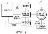
本発明の一実施形態による適応誘導安定器10の一般的な構成を示すブロック図を、図1に示している。示すように、適応誘導安定器10は、一般的には、回路の動作を制御するマイクロプロセッサ12、磁場を生成するための多タップ一次巻線14、一次巻線14に与えられる信号を生成する波形器及び駆動下位回路16、一次巻線14に与えられた信号を監視し、マイクロプロセッサ12に対応するフィードバックを提供する電流感知下位回路18、波形器及び駆動下位回路16のキャパシタンス値を調節するためのキャパシタンススイッチ20、及び、多タップ一次巻線14のインダクタンスを調節するためのインダクタンススイッチ22を含む。マイクロプロセッサは、様々な供給業者製の広く普及した、従来のマイクロプロセッサである。 A block diagram illustrating a general configuration of an adaptive induction ballast 10 according to one embodiment of the present invention is shown in FIG. As shown, the adaptive induction ballast 10 generally generates a signal applied to a
キャパシタンススイッチ20は、一般的には、コンデンサの2つのバンク、及びトランジスタのような複数のスイッチを含み、それらのスイッチは、マイクロプロセッサにより、その2つのコンデンサバンクの値を制御するように、選択的に作動可能である。各バンク内のコンデンサは、可能なキャパシタンス値の望まれる範囲及び分布に依って、直列又は並列に配置されることができる。コンデンサの第一のバンクは、上記の引用出願に示す既存の共振探索安定器のコンデンサ271と置き換わる。同様に、コンデンサの第二のバンクは、上記の引用特許出願に示す既存の共振探索安定器のコンデンサ272と置き換わる。事実上、キャパシタンススイッチ20は、既存の共振探索安定器のコンデンサ271及び272を、可変コンデンサにし、その値は、マイクロプロセッサ12により制御される。そのかわりに、説明したキャパシタンススイッチ20を、可変キャパシタンスを提供することのできる他の回路で置き換えることもできる。
インダクタンススイッチ22は、一般的には、多タップ一次巻線14、及びトランジスタのような複数のスイッチを含み、それらのスイッチは、マイクロプロセッサ12により、一次巻線14のインダクタンスの値を制御するように、選択的に作動可能である。多タップ一次巻線14は、添付の特許出願に示す既存の共振探索安定器の一次巻線270と置き換わる。事実上、インダクタンススイッチ22は、一次巻線14の巻数を変えることにより、既存の共振探索安定器の一次巻線270を可変インダクタンスコイルにし、その値は、マイクロプロセッサ12によって制御される。そのかわりに、説明したインダクタンススイッチ22を、可変インダクタンスを提供することのできる他の回路で置き換えることもできる。
一般的な動作では、マイクロプロセッサ12は、電流感知下位回路18から入力を受け取るようにプログラムされ、それは、一次巻線14に与えられた電流を示している。マイクロプロセッサ12は、キャパシタンススイッチ20、及びインダクタンススイッチ22を別々に調整して、回路に利用可能なキャパシタンス値及びインダクタンス値の範囲全体を循環するように、プログラムされる。マイクロプロセッサ12は、キャパシタンス及びインダクタンスの値を調整すると同時に、電流感知回路18からの入力を監視し続けて、どの値が、一次巻線14に最適な電流を提供するかを定める。次に、マイクロプロセッサ12は、適応安定器を、最適設定にロックする。 In general operation, the
添付の特許出願の共振探索誘導安定器を、適応誘導安定回路10の実施形態に適応させるのに必要な変更の幾つかを、図2の概略図に示す。 Some of the modifications necessary to adapt the resonant search induction ballast of the attached patent application to the embodiment of the adaptive induction stabilization circuit 10 are shown in the schematic diagram of FIG.
既存の共振探索安定器は、米国特許出願第10/246,155号でずっと詳細に説明されるが、これに対して、その回路の全体像は、本発明のより完全な理解に役立つであろう。安定フィードバック回路が点Aにおいて接続され、制御回路が点Bにおいて接続される。発振器144は、駆動146を介して、半ブリッジインバータ148に交流信号を提供する。半ブリッジインバータは、タンク回路150に電力を供給する。電流感知回路218は、発振器144にフィードバックを提供する。フィードバック回路、制御回路、発振器、半ブリッジインバータ、駆動及び電流感知回路218、加えて、他の支持回路を、上記の引用特許出願で、より完全に説明する。 Existing resonant search ballasts are described in greater detail in US patent application Ser. No. 10 / 246,155, whereas the overall picture of the circuit will help a more complete understanding of the present invention. A stable feedback circuit is connected at point A and a control circuit is connected at point B. The
図2で、Eにおいて位相遅延を挿入することができ、それは、遅延線として制御することができるであろう、又はさらに、この信号を遅延させるために、DSP(デジタル信号処理)を使用することもできるであろう。位相を絞り、二次振幅を制御するために、この遅延を使用することができる。Fにおいて、スイッチキャパシタンスは、調整可能な一次インダクタンスに基づいて、共振周波数を調整することができる。キャパシタンスのスイッチを入れる、及び切るために、単純なトランジスタを使用することができる。負荷と整合するように、一次インダクタが変化するとき、キャパシタンスが変わる。Gにおいて、一次インダクタンスを切り替えて、二次回路に必要な電力を調整することができる。その負荷情報を用いて、要求される電力を提供するのに必要とされるように、制御プロセッサは、インダクタンスを調整することができる。マイクロプロセッサによって制御されるトランジスタ、及び一次インダクタの多タップを使って、インダクタンスを切り替えることができる。 In Figure 2, a phase delay can be inserted at E, which could be controlled as a delay line, or even use DSP (digital signal processing) to delay this signal Could also do. This delay can be used to throttle the phase and control the secondary amplitude. At F, the switch capacitance can adjust the resonant frequency based on the adjustable primary inductance. Simple transistors can be used to switch on and off the capacitance. The capacitance changes when the primary inductor changes to match the load. In G, the primary inductance can be switched to adjust the power required for the secondary circuit. With that load information, the control processor can adjust the inductance as needed to provide the required power. The inductance can be switched using a microprocessor controlled transistor and multiple taps of the primary inductor.
適応誘導安定回路の動作シーケンスを、図3と絡めて、より詳細に説明する。動作中、一次巻線14に電力を与える前に、図示されたシステムは、負荷が存在することを確認するまで一時停止する。これは、電力を節約し、各誘導動力装置に、一次巻線に隣接したリードスイッチを作動させる磁気を提供することにより、成されるであろう。そのかわり、誘導動力装置が存在するとき、ユーザが電源に関与することができるように、ユーザ作動スイッチ(示されていない)を提供することもできる。更なる代替として、誘導動力装置が、一次巻線によって、その存在を信号送信するように置かれるとき、それは、スイッチを機械的に作動させるように構成されるであろう。更なる代替として、スイッチング機構を取り除くことができ、安定回路は、負荷の存在に関わらず、一次巻線14に電力を提供することができる。 The operation sequence of the adaptive induction stabilization circuit will be described in more detail in conjunction with FIG. In operation, prior to applying power to the primary winding 14, the illustrated system pauses until it confirms that a load is present. This would be done by conserving power and providing each induction power unit with magnetism that activates a reed switch adjacent to the primary winding. Alternatively, a user actuated switch (not shown) can be provided so that the user can participate in the power supply when an inductive power unit is present. As a further alternative, when the inductive power unit is placed by the primary winding to signal its presence, it will be configured to mechanically actuate the switch. As a further alternative, the switching mechanism can be eliminated and the ballast circuit can provide power to the primary winding 14 regardless of the presence of a load.
電源回路が作動されると、回路は、一次巻線に与えられた電流を最適化するように、その周波数を調整する。初期キャパシタンス及びインダクタンス値において、適当な動作周波数が定められた後、マイクロプロセッサは、安定回路をその動作周波数にロックし、次に、多タップ一次巻線によって利用可能なインダクタンス値の範囲全体にわたって循環し始める。インダクタンス値のどの変化の後にも、マイクロプロセッサは、その動作周波数をロック解除し、安定回路が共振を探索して、一次巻線に最適な電流を提供する周波数に落ち着くことを可能にする。どの値が一次巻線に最適な電流を提供するか、を定めるまで、マイクロプロセッサは、利用可能なインダクタンス値全体にわたって循環し続ける。一実施形態では、適切なインダクタンス値を定めるために、順次走査処理を使用する。これは、最低インダクタンス値で走査処理を開始し、インダクタンス値の変化が、一次巻線に与えられた電流の減少という結果になるまで、インダクタンス値を順次増大させることによって、実現される。次に、マイクロプロセッサが、最大電流が実現された一インダクタンス値に、減少し戻す。そのかわりに、走査処理が、最高インダクタンス値で始まり、インダクタンス値の変化が、一次巻線に与えられた電流の減少という結果になるまで、インダクタンス値を順次減少させることもできる。次に、マイクロプロセッサが、最大電流が実現された一インダクタンス値に、増大し戻す。更なる代替として、マイクロプロセッサは、各インダクタンス値全体をステップして、対応する電流を定め、各値全体にわたってステップした後、一次巻線に最大電流を提供したインダクタンス値に戻すこともできる。 When the power circuit is activated, the circuit adjusts its frequency to optimize the current applied to the primary winding. After the appropriate operating frequency is determined at the initial capacitance and inductance values, the microprocessor locks the ballast circuit to that operating frequency and then circulates across the range of inductance values available by the multi-tap primary winding. Begin to. After any change in inductance value, the microprocessor unlocks its operating frequency, allowing the ballast circuit to search for resonance and settle to a frequency that provides the optimum current for the primary winding. The microprocessor continues to cycle through the available inductance values until it determines which value provides the optimum current for the primary winding. In one embodiment, a sequential scanning process is used to determine an appropriate inductance value. This is achieved by starting the scanning process with the lowest inductance value and sequentially increasing the inductance value until a change in the inductance value results in a decrease in the current applied to the primary winding. The microprocessor then decreases back to the one inductance value where the maximum current is achieved. Alternatively, the inductance value can be decreased sequentially until the scanning process begins with the highest inductance value and the change in inductance value results in a decrease in the current applied to the primary winding. The microprocessor then increases back to one inductance value where the maximum current is achieved. As a further alternative, the microprocessor can step through each inductance value to define a corresponding current, and step through each value before returning to the inductance value that provided the maximum current to the primary winding.
適切なインダクタンス値が定められた後、マイクロプロセッサは、回路をその定められたインダクタンス値においてロックし、キャパシタンス値全体にわたって循環し始める。一実施形態では、マイクロプロセッサは、一次巻線に最大電流を提供するキャパシタンスを定めるために、順次走査技術を使用する。その走査処理は、インダクタンス値についての走査処理と絡めて上で説明したように、最低キャパシタンス値から上に向かって、又は最高キャパシタンス値から下に向かって進行することができる。順次走査処理の代替として、マイクロプロセッサは、各キャパシタンス値全体にわたってステップし、対応する電流を定め、各値全体にわたってステップした後、一次巻線に最大電流を提供したキャパシタンス値に戻ることもできる。 After the appropriate inductance value is determined, the microprocessor locks the circuit at the determined inductance value and begins to cycle through the capacitance value. In one embodiment, the microprocessor uses a progressive scanning technique to define a capacitance that provides maximum current to the primary winding. The scanning process can proceed from the lowest capacitance value up or from the highest capacitance value down as described above in connection with the scanning process for inductance values. As an alternative to the progressive scan process, the microprocessor can step through each capacitance value, define a corresponding current, and step through each value before returning to the capacitance value that provided the maximum current to the primary winding.
この実施形態では、適切なインダクタンス値が定められると、安定回路の周波数は変化することが許されない。そのかわりに、マイクロプロセッサは、キャパシタンス値のどの変化の後も、安定回路が共振を探索することを可能にするように、プログラムされることもできる。 In this embodiment, once an appropriate inductance value is determined, the frequency of the ballast circuit is not allowed to change. Alternatively, the microprocessor can be programmed to allow the ballast circuit to search for resonance after any change in capacitance value.
代替の実施形態では、マイクロプロセッサは、電源回路のキャパシタンス値のみ、又はインダクタンス値のみの調整を提供するように、プログラムされることもできる。前者の代替の実施形態では、多タップ一次巻線は、従来の単タップ一次巻線で置き換えることができ、かつ、インダクタンススイッチを取り除くことができる。後者の代替の実施形態では、コンデンサバンクは、コンデンサの単一セットで置き換えることができ、かつキャパシタンススイッチを取り除くことができる。更なる代替の実施形態では、マイクロプロセッサは、インダクタンスを調整する前に、キャパシタンスを調整するようにプログラムされることができる。 In alternative embodiments, the microprocessor can also be programmed to provide adjustment of only the capacitance value or only the inductance value of the power supply circuit. In the former alternative embodiment, the multi-tap primary winding can be replaced with a conventional single-tap primary winding and the inductance switch can be removed. In the latter alternative embodiment, the capacitor bank can be replaced with a single set of capacitors and the capacitance switch can be removed. In a further alternative embodiment, the microprocessor can be programmed to adjust the capacitance before adjusting the inductance.
上で言及したように、本発明は、共振探索安定器とからめての使用に限定されない。他の応用例では、電流センサを安定器内に組み込んで、一次巻線に与えられた電流を表す入力を、マイクロプロセッサに提供することができる。共振探索安定器のない動作中、マイクロプロセッサは、別々に、様々なキャパシタンス値及びインダクタンス値全体にわたって循環して、一次巻線に最適な電力を提供する値を定めるであろう。 As mentioned above, the present invention is not limited to use in conjunction with resonant search ballasts. In other applications, a current sensor can be incorporated into the ballast to provide an input to the microprocessor that represents the current applied to the primary winding. During operation without a resonant search ballast, the microprocessor will separately cycle through various capacitance and inductance values to determine values that provide optimal power to the primary winding.
更なる代替の実施形態では、適応誘導安定器10は、その安定器10が位相を絞り、二次振幅を制御することを可能にする位相遅延回路(示されていない)を含むことができる。位相遅延回路は、遅延線、又は、演算増幅器210に続く波形器及び駆動回路16に接続されたデジタル信号プロセッサ(DSP)を含むことができる。 In a further alternative embodiment, the adaptive induction ballast 10 can include a phase delay circuit (not shown) that allows the ballast 10 to throttle the phase and control the secondary amplitude. The phase delay circuit may include a delay line or a digital signal processor (DSP) connected to the waveform amplifier and drive
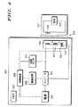
さらに、上で表現した考え及び概念を具現化する、適応非接触エネルギー伝送システムの更なる実施形態を、図4のブロック図に示す。適応非接触エネルギー伝送システムは、適応誘導電源305、及び遠隔装置307から構成される。 Furthermore, a further embodiment of an adaptive contactless energy transmission system embodying the ideas and concepts expressed above is shown in the block diagram of FIG. The adaptive contactless energy transmission system is composed of an adaptive
よく知られるように、電源310は、インバータ312にDC(直流)電力を提供するDC電源である。インバータ312は、DC電力をAC(交流)電力に変換する。インバータ312は、タンク回路314にAC電力を供給するAC電源として作動する。タンク回路314は、遠隔装置307の二次巻線316に誘導結合される。 As is well known, the
遠隔装置307の二次巻線316は、全く鉄心を持たない。線322は、遠隔装置307と適応誘導電源305との間のエアギャップを示している。 The secondary winding 316 of the
遠隔装置307は負荷320を有する。負荷320は、マイクロコンデンサ又は蓄電池のような充電式装置を含むことができるであろう。そのかわりに、負荷320は、電球、無線受信機、又は、遠隔装置307が適応誘導電源305の近くに置かれたときにはいつでも、適応誘導電源305から電力を受け取るようにされた任意の他の電気装置とすることもできるであろう。
回路センサ324は、タンク回路314、及びインバータ312に結合される。回路センサ324はまた、制御装置326にも結合される。回路センサ324は、適応誘導電源305の動作パラメータに関する情報を提供する。例えば、回路センサ324は、タンク回路314内の電流の位相、周波数、及び振幅に関する情報を制御装置326に提供するために使用される電流センサとすることもできるであろう。
制御装置326は、インテル8051、又はモトローラ6811、又はそれらマイクロコントローラーの多くの変形のうちのいずれかのような、以下に説明する機能を実行するようにプログラムされた多数の汎用マイクロコントローラーのうちのいずれか一つとすることができるであろう。制御装置326は、チップ上に、ROM(読み出し専用メモリ)及びRAM(ランダムアクセスメモリ)を持つことができるであろう。制御装置326は、適応誘導電源内の様々な機能を制御するための一連のアナログ及びデジタル出力も持つことができるであろう。 The
制御装置326は、メモリ327に接続される。制御装置326はまた、駆動回路328にも結合される。駆動回路328は、インバータ312の周波数及びタイミングのような、インバータ312の動作を調整する。駆動回路328は、多数の異なる手法で構成されることができるであろう。例えば、駆動回路328は、トランジスタ、抵抗器、及びコンデンサのような別個の構成部品で構成されることができるであろう、すなわち、それは、インバータを駆動するように設計された個別集積回路とすることができるであろう、又は、制御装置326がマイクロコントローラーである場合には、制御装置326の機能構成部品とすることもできるであろう。 The
制御装置326はまた、電源310にも結合されるであろう。制御装置326は、電源310のレール電圧を操作することができる。良く知られるように、電源310のレール電圧を変えることにより、インバータ312の出力の振幅もまた変わる。
最後に、制御装置326は、タンク回路314の可変インダクタ330及び可変コンデンサ332に結合される。制御装置326は、8051型マイクロコントローラーのようなマイクロコントローラーとすることができるであろう。そのかわりに、制御装置326は、更なる支持回路を持つマイクロプロセッサとすることもできるであろう。 Finally, the
制御装置326は、可変インダクタ330のインダクタンス、又は可変コンデンサ332のキャパシタンスを変更することができる。例えば、更なるコンデンサ又はインダクタのスイッチを入れる又は切ることによって、或いは、可変インダクタ330又は可変コンデンサ332の物理特性を変えることにより、これを実現することができるであろう。可変インダクタ330のインダクタンス、及び、可変コンデンサ332のキャパシタンスを変更することにより、タンク回路314の共振周波数を変えることができる。 The
可変インダクタ330のインダクタンス又は可変コンデンサ332のキャパシタンス、あるいはその両方を変更することにより、タンク回路314は、第一共振周波数及び第二共振周波数を持つことができる。タンク回路314はまた、幾つかの共振周波数を持つこともできるであろう。本出願で使用される限り、「共振周波数」という語は、タンク回路314が共振する周波数帯域を参照する。良く知られるように、タンク回路は、共振周波数を持つが、周波数のある範囲内では共振し続けるであろう。 By changing the inductance of the
可変インダクタ330は、サイリスタ制御可変インダクタ、圧縮性可変インダクタ、平行積層鉄心可変インダクタ、選択固定インダクタをタンク回路314内に配置することのできる一連のインダクタ及びスイッチ、又は任意の他の制御可能な可変インダクタとすることができるであろう。可変コンデンサ332は、スイッチキャパシタアレイ、選択固定コンデンサをタンク回路314内に配置することのできる一連の固定コンデンサ及びスイッチ、又は、任意の他の制御可能な可変コンデンサとすることができるであろう。 The
タンク回路314はまた、一次巻線334を含む。一次巻線334及び可変インダクタ330が、別々に示されている。そのかわりに、一次巻線334及び可変インダクタ330が、単一要素に結合されることもできるであろう。 The
タンク回路314は、直列共振タンク回路として示されている。並列共振タンク回路もまた、使用することができるであろう。
図5A及び5Bは、図4に示す適応非接触エネルギー伝送システムの適応誘導電源305の動作を示すフローチャートを示している。 5A and 5B show a flowchart showing the operation of the adaptive
オンにされると(ステップ400)、制御装置326は、タンク回路314があらかじめ選択された初期共振周波数で動作するように、可変インダクタ330のインダクタンス及び可変コンデンサ332のキャパシタンスをセットすることにより、タンク回路314の共振周波数を初期化する。ステップ402。制御装置326は、駆動回路328を、あらかじめ選択された周波数において、あらかじめ選択された位相オフセットで動作するように初期化する。制御装置326は、電源310を、所定のレール電圧で動作するように初期化する。ステップ402。 When turned on (step 400), the
電力を節約して使うために、適応誘導電源305は、最初に電圧を加えられた時、非常に低いレベルで電力を供給するように初期化されることができるであろう。そのかわりに、より適度なレベルで電力を供給するように適応誘導電源305を初期化して、幾つかの共通遠隔装置を調整することもできるであろう。 To conserve power and use, the adaptive
次に、制御装置326は、動作パラメータの公称範囲をセットする。ステップ404。電源の動作パラメータは、システム全体にわたる電流及び電圧の様々な基準である。例えば、ピークピークインバータ電圧、一次巻線を流れるRMS電流、及び一次巻線を流れる電流の位相オフセットが、すべての動作パラメータである。例えば、動作範囲は、インバータ電圧と電圧電流との間の位相オフセットの範囲、電流振幅の範囲、及びインバータ出力電圧の範囲を含むことができるであろう。更なる例として、動作範囲は、20°程度の電流位相オフセット、及び1/2アンペアと1アンペアの間の電流振幅で、5ボルトから5.3ボルトのインバータ電圧とすることもできるであろう。 Next, the
公称範囲は、動作パラメータについて可能な値の許容範囲である。動作パラメータが公称範囲内でない場合には、電源は効率的に動作していない。 The nominal range is an acceptable range of possible values for the operating parameter. If the operating parameters are not within the nominal range, the power supply is not operating efficiently.
図5に戻ると、次に、システムは停止する。ステップ406。制御装置326は、適応誘導電源305の動作パラメータを絶えず監視する。動作パラメータが公称範囲内にある場合には、回路は停止し続ける。ステップ408。 Returning to FIG. 5, the system then stops.
遠隔装置307が一次巻線334の近くに置かれる時、電力は、適応誘導電源305から引き出される。結果として、動作パラメータが変化する。動作パラメータが公称範囲外にある場合には、制御装置326は、適応誘導電源305を再構成する。 When
従って、適応誘導電源305が初期低電力設定を有する場合には、適応誘導電源305は、遠隔装置の存在を感知し、電力をより適度なレベルまで自動的に増大させるであろう。 Thus, if the adaptive
明らかに、適応誘導電源305の再構成は、公称範囲外にある一動作パラメータによって引き起こされることができるであろう、或いは、適応誘導電源305の再構成は、公称範囲外にある動作パラメータの組み合わせによって引き起こされることができるであろう。一次巻線を流れる電流の位相のみを監視することで、充分である。しかしながら、他の動作パラメータを同時に測定及び計量する様々な拡張を、容易に考え付くこともできるであろう。 Obviously, the reconfiguration of the adaptive
第一に、制御装置326は、駆動回路328に、インバータ312のデューティサイクルを変えさせる。ステップ410。インバータ312のデューティサイクルが変えられ、その変えられたデューティサイクルがメモリ327内に格納される。 First, the
動作パラメータが再び測定される。ステップ412。動作パラメータがまだ公称範囲外である場合には、「既知の最良設定」フラグをチェックする。ステップ414。「既知の最良設定」フラグを、以下に説明する。 The operating parameters are measured again.
「既知の最良設定フラグ」がセットされていない場合には、制御装置326は、タンク回路314内で、インバータ周波数を調整し、さらに共振を維持することができるかどうかを判断する。ステップ418。制御装置326は、第一に、タンク回路314の最高及び最低共振周波数を見つける。 If the “known best setting flag” is not set, the
可変インダクタ330及び可変コンデンサ332のどの特定の構成における、タンク回路314の最高及び最低共振周波数も、メモリ327内に格納することができるであろう。代替の実施形態では、タンク回路314の最高及び最低共振周波数を、一次巻線334のインダクタンス、可変インダクタ330のインダクタンス、及び可変コンデンサ332のキャパシタンスから計算することができるであろう。次に、制御装置326は、タンク回路314の最高及び最低周波数を、インバータ312の現在の動作周波数と比較する。 The highest and lowest resonant frequencies of
可能な場合には、制御装置326は、駆動回路328に、インバータ周波数を調整させ、その新しいインバータ周波数をメモリ327内に格納する。ステップ420。回路は停止状態に戻る。ステップ406。インバータ周波数を、タンク回路314の現在の構成の共振周波数内で調整することができない場合には、制御装置326が、タンク回路314の構成を変更できるかどうか定める。ステップ422。 If possible, the
それを変更することができる場合には、制御装置326が、現在の周波数、デューティサイクル、レール電圧、タンク回路構成、及び動作パラメータを、メモリ327内に格納する。ステップ424。次に、制御装置326は、タンク回路共振周波数を調整する。ステップ426。タンク回路共振周波数の調整は、可変インダクタ330のインダクタンス、及び可変コンデンサ332のキャパシタンスを変えることにより、遂行される。 If it can be changed, the
次に、レール電圧を変えることができるであろう。ステップ428。タンク回路314の共振周波数が変えられたので、その動作パラメータについての新しい公称範囲が計算される、又はメモリ327から読み込まれる。ステップ430。次に、電源は停止に戻る。ステップ406。 The rail voltage could then be changed.
タンク回路314の構成をさらに変更できない場合には、制御装置326は、先の構成の最良のものを探索する。ステップ432。制御装置326は、前に格納された動作パラメータを比較し、最良の構成を選択する。 If the configuration of the
最良の構成を選択した後、制御装置326は、その構成について、適応誘導電源305の様々な設定をメモリから検索する。ステップ433。次に、制御装置326は、可変インダクタ30のインダクタンス、及び可変コンデンサ32のキャパシタンスをセットすることにより、タンク回路314の構成をセットする。ステップ434。次に、制御装置326は、インバータ312の周波数をセットする。ステップ436。次に、制御装置326は、インバータ312のデューティサイクルをセットする。ステップ438。制御装置326は、電源310のレール電圧をセットする。ステップ440。 After selecting the best configuration, the
次に、制御装置326は、予想された動作パラメータをメモリ327内に格納する。ステップ442。そのかわりに、制御装置326は、メモリ327内の予想動作パラメータにポインタをセットすることもできるであろう。次に、制御装置326は、「既知の最良設定」フラグをセットする。ステップ444。次に、電源は、停止状態に戻る。ステップ406。「既知の最良設定」フラグは、適応誘導電源305によって使用されている現在の設定が最も利用可能であることの、制御装置326への表示である。 Next, the
「既知の最良設定」フラグがセットされる場合には、たとえ動作パラメータが公称範囲外であっても、システムは、その最良の設定で動作している。従って、インバータ周波数、共振回路周波数、インバータのデューティサイクル、又はレール電圧への更なる変更は、システムの何の改善にもならないという結果になるであろう。「既知の最良設定」フラグがセットされると、システムは、その動作パラメータが予想された動作パラメータとほぼ等しいか否かをチェックする。 If the “known best settings” flag is set, the system is operating at its best settings even if the operating parameters are outside the nominal range. Thus, further changes to the inverter frequency, resonant circuit frequency, inverter duty cycle, or rail voltage will result in no improvement of the system. When the “known best set” flag is set, the system checks whether the operating parameter is approximately equal to the expected operating parameter.
従って、既知の最良設定フラグがセットされる(ステップ414参照)場合には、制御装置326は、現在の動作パラメータが予想された動作パラメータとほぼ同じであるかどうかチェックする。ステップ446。その場合には、電源に対する更なる調整は、性能の何の改善にもならないという結果になり、それゆえ、システムはただ単に、停止状態に戻るだけである。ステップ406。 Accordingly, if the known best setting flag is set (see step 414), the
反対に、現在の動作パラメータが、予想された動作パラメータとほぼ等しくない場合には、その既知の最良設定フラグがクリアされる。ステップ448。適応誘導電源305を再構成するプロセスは続行する。ステップ422。 Conversely, if the current operating parameter is not approximately equal to the expected operating parameter, the known best setting flag is cleared. Step 448. The process of reconfiguring the adaptive
このように、説明した適応非接触エネルギー伝送システムは、様々な異なる装置を動的に取り扱うことができる。適応誘導電源305は、異なる負荷を持つ様々な装置に自動的に適応し、その電源についての最適な動作構成を絶えず定める。 Thus, the described adaptive contactless energy transfer system can dynamically handle a variety of different devices. The adaptive
さらに、適応誘導電力305によって、一以上の装置に同時に電力を供給することができる。新たな装置が適応誘導電源305の近くに置かれる時、制御装置326は、効率を維持するように、適応誘導電源305の動作パラメータを絶えず調整する。これは、一つの単一電源が多数の異なる装置に電力を提供するのに備える。その装置を、適応誘導電源305に直接隣接して置く必要はない。それは、適応誘導電源305から、様々な距離をあけて配置することができる。例えば、それにより、シールド光が適応誘導電源305の近くに蓄積され、たとえ適応誘導電源305からの距離が各々の光ごとに異なっていても、どの光も放射されるような電源を構成することが可能である。 Furthermore, the adaptive
上記の説明は、好ましい実施形態に関するものである。添付の本特許請求の範囲で定められる本発明の技術的範囲から外れることなく、様々な代替及び変更が成され得り、それらは、均等論を含む特許法の主義により解釈されるべきである。例えば、冠詞「a」、「an」、「the」、又は「said」を使った単数形の請求要素への如何なる参照も、その要素を単数に限定するものとして解釈されるものではない。 The above description is of the preferred embodiment. Various alternatives and modifications may be made without departing from the scope of the invention as defined in the appended claims, which should be construed in accordance with the principles of patent law, including doctrine of equivalents. . For example, any reference to a singular claim element using the articles “a”, “an”, “the”, or “said” is not to be construed as limiting the element to the singular.
Claims (56)
Translated fromJapanese前記タンク回路を動的に再構成するための制御装置、
を備えることを特徴とする、前記装置に誘導結合する非接触電源。A tank circuit for inductively coupling to the device; and
A control device for dynamically reconfiguring the tank circuit;
A non-contact power source inductively coupled to the device.
ことを特徴とする請求項1に記載の非接触電源。The contactless power supply according to claim 1, wherein the tank circuit includes a variable capacitor.
ことを特徴とする請求項2に記載の非接触電源。3. The non-contact power supply according to claim 2, wherein the control device is coupled to the variable capacitor.
ことを特徴とする請求項3に記載の非接触電源。4. The contactless power supply according to claim 3, wherein the tank circuit is coupled to an inverter.
ことを特徴とする請求項4に記載の非接触電源。The contactless power supply according to claim 4, wherein a drive circuit is coupled to the inverter.
ことを特徴とする請求項5に記載の非接触電源。6. The contactless power supply according to claim 5, wherein the inverter has an inverter frequency, and the drive circuit adjusts the inverter frequency.
ことを特徴とする請求項6に記載の非接触電源。7. The non-contact power supply according to claim 6, wherein the inverter has a duty cycle, and the drive circuit adjusts the duty cycle of the inverter.
ことを特徴とする請求項7に記載の非接触電源。The contactless power supply according to claim 7, wherein a power supply is coupled to the inverter.
ことを特徴とする請求項8に記載の非接触電源。9. The non-contact power supply according to claim 8, wherein the power supply has a rail voltage, and the rail voltage can be changed by the control device.
ことを特徴とする請求項9に記載の非接触電源。The non-contact power source according to claim 9, wherein a sensor is coupled to the inverter.
ことを特徴とする請求項10に記載の非接触電源。11. The non-contact power supply according to claim 10, wherein the inverter has a duty cycle, and the control device changes the duty cycle according to information from the sensor.
ことを特徴とする請求項11に記載の非接触電源。12. The non-contact power supply according to claim 11, wherein the inverter has an inverter frequency, and the control device changes the inverter frequency in accordance with information from the sensor.
ことを特徴とする請求項12に記載の非接触電源。The contactless power supply according to claim 12, wherein the control device is coupled to a variable inductor.
ことを特徴とする請求項13に記載の非接触電源。The contactless power supply according to claim 13, wherein the tank circuit is coupled to an inverter.
ことを特徴とする請求項14に記載の非接触電源。15. The non-contact power source according to claim 14, wherein a drive circuit is coupled to the inverter.
ことを特徴とする請求項15に記載の非接触電源。The contactless power supply according to claim 15, wherein the drive circuit adjusts the inverter frequency.
ことを特徴とする請求項16に記載の非接触電源。The contactless power supply according to claim 16, wherein the drive circuit adjusts the duty cycle.
ことを特徴とする請求項17に記載の非接触電源。The contactless power supply according to claim 17, wherein a power supply is coupled to the inverter.
ことを特徴とする請求項18に記載の非接触電源。19. The non-contact power source according to claim 18, wherein the power source has a rail voltage, and the control device can change the rail voltage.
ことを特徴とする請求項19に記載の非接触電源。The contactless power supply according to claim 19, wherein a sensor is coupled to the inverter.
ことを特徴とする請求項20に記載の非接触電源。21. The non-contact power supply according to claim 20, wherein the control device changes the duty cycle of the inverter according to information from the sensor.
ことを特徴とする請求項21に記載の非接触電源。The contactless power supply according to claim 21, further comprising a memory coupled to the control device.
ことを特徴とする請求項22に記載の非接触電源。The contactless power supply according to claim 22, wherein the tank circuit includes a variable inductor.
ことを特徴とする請求項23に記載の非接触電源。24. The non-contact power source according to claim 23, wherein the tank circuit is coupled to an inverter.
ことを特徴とする請求項24に記載の非接触電源。The contactless power supply according to claim 24, wherein a drive circuit is coupled to the inverter.
ことを特徴とする請求項25に記載の非接触電源。26. The contactless power supply according to claim 25, wherein the inverter has an inverter frequency, and the drive circuit adjusts the inverter frequency.
ことを特徴とする請求項26に記載の非接触電源。27. The non-contact power supply according to claim 26, wherein the inverter has a duty cycle, and the drive circuit adjusts the duty cycle.
ことを特徴とする請求項27に記載の非接触電源。28. The non-contact power source according to claim 27, wherein a power source is coupled to the inverter.
ことを特徴とする請求項28に記載の非接触電源。29. The non-contact power source according to claim 28, wherein the power source has a rail voltage, and the control device adjusts the rail voltage.
ことを特徴とする請求項29に記載の非接触電源。30. The non-contact power source according to claim 29, wherein a sensor is coupled to the inverter.
ことを特徴とする請求項30に記載の非接触電源。31. The non-contact power supply according to claim 30, wherein the control device changes the duty cycle in accordance with information from the sensor.
ことを特徴とする請求項31に記載の非接触電源。32. The non-contact power supply according to claim 31, wherein the control device changes the inverter frequency in accordance with information from the sensor.
前記タンク回路の動作パラメータを感知するためのセンサ、及び、
前記センサに応じて前記タンク回路を構成するための、前記センサに結合される制御装置、
を備えることを特徴とする、装置に誘導的に電力を供給するための非接触電源。Tank circuit,
A sensor for sensing operating parameters of the tank circuit; and
A controller coupled to the sensor for configuring the tank circuit in response to the sensor;
A non-contact power source for inductively supplying power to the apparatus.
ことを特徴とする請求項33に記載の非接触電源。The non-contact power source according to claim 33, wherein the tank circuit includes a variable capacitor.
ことを特徴とする請求項34に記載の非接触電源。The contactless power supply according to claim 34, wherein the tank circuit includes a variable inductor.
ことを特徴とする請求項35に記載の非接触電源。36. The non-contact power source according to claim 35, wherein the tank circuit includes a primary winding.
ことを特徴とする請求項36に記載の非接触電源。The contactless power supply according to claim 36, wherein the primary winding and the variable inductor are separate.
ことを特徴とする請求項37に記載の非接触電源。38. The contactless power supply according to claim 37, wherein the primary winding and the variable inductor are integrated.
前記タンク回路からの電力伝送効率を検出するためのセンサ、及び、
前記電力伝送効率が下がる場合には、前記可変要素を変化させるための、前記センサに応答する制御装置、
を備えることを特徴とする非接触電源。A tank circuit that has a resonance frequency and a variable element for changing the resonance frequency and can be attached to an AC power source;
A sensor for detecting power transmission efficiency from the tank circuit; and
A controller responsive to the sensor for changing the variable element when the power transfer efficiency is reduced;
A non-contact power source comprising:
前記動作パラメータの変化に応じて、前記共振周波数を変化させること、
を含むことを特徴とする方法。A method of operating a contactless power supply having a tank circuit inductively coupled to a load having a resonant frequency and further having operating parameters to power the load,
Changing the resonance frequency in response to a change in the operating parameter;
A method comprising the steps of:
前記動作パラメータの変化に応じて、前記AC電源周波数を変化させること、
をさらに含むことを特徴とする請求項40に記載の方法。The tank circuit is coupled to an AC power source having an AC power frequency;
Changing the AC power frequency in response to a change in the operating parameter;
41. The method of claim 40, further comprising:
前記動作パラメータの変化に応じて、前記デューティサイクルを変化させること、
をさらに含むことを特徴とする請求項41に記載の方法。The AC power source is an inverter, the inverter has a duty cycle;
Changing the duty cycle in response to a change in the operating parameter;
42. The method of claim 41, further comprising:
前記動作パラメータの変化に応じて、前記レール電圧を変化させること、
をさらに含むことを特徴とする請求項42に記載の方法。The inverter is coupled to a DC power supply having a rail voltage;
Changing the rail voltage in response to a change in the operating parameter;
43. The method of claim 42, further comprising:
前記可変コンデンサの前記キャパシタンスを変化させるステップ、
を含むことを特徴とする請求項43に記載の方法。The tank circuit has a capacitance and a variable capacitor that adjusts the resonant frequency of the tank circuit;
Changing the capacitance of the variable capacitor;
44. The method of claim 43, comprising:
前記可変インダクタの前記インダクタンスを変化させるステップ、
を含むことを特徴とする請求項44に記載の方法。The tank circuit has an inductance and a variable inductor for adjusting the resonance frequency of the tank circuit;
Changing the inductance of the variable inductor;
45. The method of claim 44, comprising:
前記可変インダクタの前記インダクタンスを変化させること、
を含むことを特徴とする請求項45に記載の方法。The tank circuit has an inductance and a variable inductor for adjusting the resonance frequency of the tank circuit;
Changing the inductance of the variable inductor;
46. The method of claim 45, comprising:
前記可変コンデンサの前記キャパシタンスを変化させるステップ、
を含むことを特徴とする請求項46に記載の方法。The tank circuit has a capacitance and a variable capacitor that adjusts the resonant frequency of the tank circuit;
Changing the capacitance of the variable capacitor;
47. The method of claim 46, comprising:
前記動作パラメータに応じて、前記レール電圧を変化させるステップ、
を含むことを特徴とする請求項44又は47に記載の方法。The inverter is coupled to a DC power supply having a rail voltage;
Changing the rail voltage according to the operating parameter;
48. The method of claim 44 or 47, comprising:
請求項48に記載の方法。49. The method of claim 48, wherein the tank circuit has a tank circuit current having a phase and the operating parameter is the phase.
前記電源は、可変共振周波数を持つタンク回路が前記負荷に誘導結合され、デューティサイクル及びインバータ周波数を持つ、レール電圧持つDC電源に結合されたインバータを持ち、公称範囲を持つ前記タンク回路の動作パラメータを検出するためのセンサを持ち、
前記動作パラメータを監視し、及び、
前記動作パラメータが前記公称範囲外になる場合には、前記デューティサイクルを第二のデューティサイクル値に変える
ステップを含むことを特徴とする方法。A method of operating a power supply to a load, comprising:
The power supply has an inverter coupled to a DC power supply having a rail voltage with a tank circuit having a variable resonance frequency inductively coupled to the load, having a duty cycle and an inverter frequency, and operating parameters of the tank circuit having a nominal range Have a sensor to detect
Monitoring the operating parameters; and
Changing the duty cycle to a second duty cycle value if the operating parameter falls outside the nominal range.
ステップをさらに含むことを特徴とする請求項50に記載の方法。51. The method of claim 50, further comprising changing the variable resonant frequency if the operating parameter remains outside the nominal range.
前記タンク回路は、第一の共振周波数を持つように構成可能であり、かつ、第二の共振周波数を持つように構成可能であり、また、公称範囲を持つ動作パラメータを持ち、前記負荷に誘導結合され、
前記動作パラメータが前記公称範囲内である場合には、前記タンク回路を、前記第一の共振周波数を持つように構成し、及び、
前記動作パラメータが前記公称範囲内でない場合には、前記タンク回路を、前記第二の共振周波数を持つように構成すること、
を含むことを特徴とする方法。A method of operating a power supply with a tank circuit to supply power to a load,
The tank circuit can be configured to have a first resonant frequency and can be configured to have a second resonant frequency, and has operating parameters having a nominal range and is induced to the load Combined,
If the operating parameter is within the nominal range, the tank circuit is configured to have the first resonant frequency; and
If the operating parameter is not within the nominal range, the tank circuit is configured to have the second resonant frequency;
A method comprising the steps of:
前記動作パラメータが前記公称範囲内である場合には、前記第一のインバータ周波数付近で前記インバータを作動させ、
前記動作パラメータが前記公称範囲内でない場合には、前記第二のインバータ周波数付近で前記インバータを作動させる
ステップを含むことを特徴とする請求項52に記載の方法。The power source has an inverter having a first inverter frequency and a second inverter frequency for supplying power to the tank circuit;
If the operating parameter is within the nominal range, operate the inverter near the first inverter frequency;
53. The method of claim 52, comprising operating the inverter near the second inverter frequency if the operating parameter is not within the nominal range.
前記タンク回路が前記第一の共振周波数で動作するように構成されるとき、前記動作パラメータを、第一の動作値として、前記メモリ内に格納し、
前記タンク回路が前記第二の共振周波数で動作するように構成されるとき、前記動作パラメータを、第二の動作値として、前記メモリ内に格納する
ステップを含むことを特徴とする請求項53に記載の方法。The power supply has memory,
When the tank circuit is configured to operate at the first resonant frequency, the operating parameter is stored in the memory as a first operating value;
54. When the tank circuit is configured to operate at the second resonant frequency, the method includes storing the operating parameter in the memory as a second operating value. The method described.
前記第一の動作値、又は前記第二の動作値、のどちらが好ましいかを定め、
前記第一の動作値、又は前記第二の動作値、のいずれかを作り出すよう動作するように、前記電源を構成する
ステップを含むことを特徴とする請求項54に記載の方法。When the operating parameter is not within the nominal range, the inverter is operating at the first inverter frequency or the second inverter frequency;
Determine which of the first operating value or the second operating value is preferred,
55. The method of claim 54, comprising configuring the power supply to operate to produce either the first operating value or the second operating value.
前記第二の動作値が好ましい場合には、前記第二の動作値を、前記予想される動作値として、前記メモリ内に格納する
ステップをさらに含むことを特徴とする請求項55に記載の方法。If the first operating value is preferred, store the first operating value as an expected operating value in the memory;
56. The method of claim 55, further comprising storing the second operating value in the memory as the expected operating value if the second operating value is preferred. .
Applications Claiming Priority (3)
| Application Number | Priority Date | Filing Date | Title |
|---|---|---|---|
| US44479403P | 2003-02-04 | 2003-02-04 | |
| US10/689,499US7212414B2 (en) | 1999-06-21 | 2003-10-20 | Adaptive inductive power supply |
| PCT/US2004/001758WO2004073150A1 (en) | 2003-02-04 | 2004-01-22 | Adaptive inductive power supply |
Related Child Applications (1)
| Application Number | Title | Priority Date | Filing Date |
|---|---|---|---|
| JP2007100163ADivisionJP4644691B2 (en) | 2003-02-04 | 2007-04-06 | Adaptive induction power supply |
Publications (2)
| Publication Number | Publication Date |
|---|---|
| JP2006518179Atrue JP2006518179A (en) | 2006-08-03 |
| JP2006518179A5 JP2006518179A5 (en) | 2007-04-05 |
Family
ID=32871931
Family Applications (2)
| Application Number | Title | Priority Date | Filing Date |
|---|---|---|---|
| JP2006502941APendingJP2006518179A (en) | 2003-02-04 | 2004-01-22 | Adaptive induction power supply |
| JP2007100163AExpired - LifetimeJP4644691B2 (en) | 2003-02-04 | 2007-04-06 | Adaptive induction power supply |
Family Applications After (1)
| Application Number | Title | Priority Date | Filing Date |
|---|---|---|---|
| JP2007100163AExpired - LifetimeJP4644691B2 (en) | 2003-02-04 | 2007-04-06 | Adaptive induction power supply |
Country Status (8)
| Country | Link |
|---|---|
| US (8) | US7212414B2 (en) |
| EP (4) | EP1590877A1 (en) |
| JP (2) | JP2006518179A (en) |
| KR (5) | KR101239041B1 (en) |
| CN (2) | CN1768467B (en) |
| MY (3) | MY144505A (en) |
| TW (2) | TWI326147B (en) |
| WO (1) | WO2004073150A1 (en) |
Cited By (14)
| Publication number | Priority date | Publication date | Assignee | Title |
|---|---|---|---|---|
| KR20090099079A (en)* | 2007-01-08 | 2009-09-21 | 액세스 비지니스 그룹 인터내셔날 엘엘씨 | Inductive power supply gas discharge lamp circuit |
| JP2010516019A (en)* | 2007-01-08 | 2010-05-13 | アクセス ビジネス グループ インターナショナル リミテッド ライアビリティ カンパニー | Induction drive gas discharge lamp circuit |
| JP2010541531A (en)* | 2007-09-28 | 2010-12-24 | アクセス ビジネス グループ インターナショナル リミテッド ライアビリティ カンパニー | Multiphase induction power supply system |
| JP2012165647A (en)* | 2007-01-02 | 2012-08-30 | Access Business Group Internatl Llc | Inductive power supply with device identification |
| KR101317293B1 (en)* | 2009-04-13 | 2013-10-14 | 도요타 지도샤(주) | Contactless power supply facilities, non-contact power receiving devices and non-contact power supply systems |
| JP2014506111A (en)* | 2010-12-29 | 2014-03-06 | 日本テキサス・インスツルメンツ株式会社 | System for wireless power transmission |
| JP2015502131A (en)* | 2011-12-13 | 2015-01-19 | 日本テキサス・インスツルメンツ株式会社 | Wireless power system and method |
| JP2015029415A (en)* | 2008-03-13 | 2015-02-12 | アクセス ビジネス グループ インターナショナル リミテッド ライアビリティ カンパニー | Inductive charging system having a plurality of primary coils |
| JP2015528689A (en)* | 2012-09-17 | 2015-09-28 | クアルコム,インコーポレイテッド | Radio transmitter static tuning |
| US9153969B2 (en) | 2010-01-14 | 2015-10-06 | Sony Corporation | Power feeding device, power receiving device and wireless power feeding system |
| JP2016007131A (en)* | 2007-03-02 | 2016-01-14 | クゥアルコム・インコーポレイテッドQualcomm Incorporated | Wireless power apparatus and methods |
| JP2016220534A (en)* | 2008-01-07 | 2016-12-22 | アクセス ビジネス グループ インターナショナル リミテッド ライアビリティ カンパニー | Induction power supply with duty cycle control |
| JP2016220421A (en)* | 2015-05-21 | 2016-12-22 | トヨタ自動車株式会社 | Non-contact power transmission device and power transmission system |
| JP2018121436A (en)* | 2017-01-25 | 2018-08-02 | 日本電波株式会社 | High voltage control device |
Families Citing this family (382)
| Publication number | Priority date | Publication date | Assignee | Title |
|---|---|---|---|---|
| US7522878B2 (en)* | 1999-06-21 | 2009-04-21 | Access Business Group International Llc | Adaptive inductive power supply with communication |
| US7212414B2 (en)* | 1999-06-21 | 2007-05-01 | Access Business Group International, Llc | Adaptive inductive power supply |
| US7065658B1 (en) | 2001-05-18 | 2006-06-20 | Palm, Incorporated | Method and apparatus for synchronizing and recharging a connector-less portable computer system |
| CA2526544C (en)* | 2003-05-23 | 2013-11-26 | Auckland Uniservices Limited | Methods and apparatus for control of inductively coupled power transfer systems |
| EP1634366B1 (en)* | 2003-05-23 | 2017-05-03 | Auckland Uniservices Limited | Frequency controlled resonant converter |
| JP4036813B2 (en)* | 2003-09-30 | 2008-01-23 | シャープ株式会社 | Non-contact power supply system |
| GB2414121B (en) | 2004-05-11 | 2008-04-02 | Splashpower Ltd | Controlling inductive power transfer systems |
| GB2414120B (en) | 2004-05-11 | 2008-04-02 | Splashpower Ltd | Controlling inductive power transfer systems |
| KR20040072581A (en)* | 2004-07-29 | 2004-08-18 | (주)제이씨 프로텍 | An amplification relay device of electromagnetic wave and a radio electric power conversion apparatus using the above device |
| US7462951B1 (en)* | 2004-08-11 | 2008-12-09 | Access Business Group International Llc | Portable inductive power station |
| NZ535390A (en) | 2004-09-16 | 2007-10-26 | Auckland Uniservices Ltd | Inductively powered mobile sensor system |
| JP4318044B2 (en) | 2005-03-03 | 2009-08-19 | ソニー株式会社 | Power supply system, power supply apparatus and method, power reception apparatus and method, recording medium, and program |
| DE102005022352A1 (en)* | 2005-05-13 | 2006-11-23 | BSH Bosch und Siemens Hausgeräte GmbH | Energy transmission device |
| US7825543B2 (en)* | 2005-07-12 | 2010-11-02 | Massachusetts Institute Of Technology | Wireless energy transfer |
| CN101860089B (en) | 2005-07-12 | 2013-02-06 | 麻省理工学院 | wireless non-radiative energy transfer |
| US7352567B2 (en)* | 2005-08-09 | 2008-04-01 | Apple Inc. | Methods and apparatuses for docking a portable electronic device that has a planar like configuration and that operates in multiple orientations |
| US7382636B2 (en)* | 2005-10-14 | 2008-06-03 | Access Business Group International Llc | System and method for powering a load |
| US20070109819A1 (en)* | 2005-11-17 | 2007-05-17 | Powell George L | Modulated tuned L/C transmitter circuits |
| WO2007069293A1 (en)* | 2005-12-12 | 2007-06-21 | Matsushita Electric Industrial Co., Ltd. | Contactless charging-type battery system, charging device, and battery pack |
| JP4813171B2 (en)* | 2005-12-16 | 2011-11-09 | 株式会社豊田自動織機 | Stator manufacturing method and manufacturing apparatus |
| US8447234B2 (en)* | 2006-01-18 | 2013-05-21 | Qualcomm Incorporated | Method and system for powering an electronic device via a wireless link |
| US9130602B2 (en) | 2006-01-18 | 2015-09-08 | Qualcomm Incorporated | Method and apparatus for delivering energy to an electrical or electronic device via a wireless link |
| US11201500B2 (en) | 2006-01-31 | 2021-12-14 | Mojo Mobility, Inc. | Efficiencies and flexibilities in inductive (wireless) charging |
| US7952322B2 (en) | 2006-01-31 | 2011-05-31 | Mojo Mobility, Inc. | Inductive power source and charging system |
| US8169185B2 (en) | 2006-01-31 | 2012-05-01 | Mojo Mobility, Inc. | System and method for inductive charging of portable devices |
| US11245287B2 (en) | 2006-03-23 | 2022-02-08 | Philips Ip Ventures B.V. | Inductive power supply with device identification |
| US7355150B2 (en) | 2006-03-23 | 2008-04-08 | Access Business Group International Llc | Food preparation system with inductive power |
| US7948208B2 (en)* | 2006-06-01 | 2011-05-24 | Mojo Mobility, Inc. | Power source, charging system, and inductive receiver for mobile devices |
| US11329511B2 (en) | 2006-06-01 | 2022-05-10 | Mojo Mobility Inc. | Power source, charging system, and inductive receiver for mobile devices |
| JP4855150B2 (en)* | 2006-06-09 | 2012-01-18 | 株式会社トプコン | Fundus observation apparatus, ophthalmic image processing apparatus, and ophthalmic image processing program |
| US9022293B2 (en) | 2006-08-31 | 2015-05-05 | Semiconductor Energy Laboratory Co., Ltd. | Semiconductor device and power receiving device |
| US8013473B2 (en)* | 2006-09-01 | 2011-09-06 | Atmel Corporation | Detector based combination regulator |
| US9129741B2 (en) | 2006-09-14 | 2015-09-08 | Qualcomm Incorporated | Method and apparatus for wireless power transmission |
| TWI339471B (en)* | 2006-12-27 | 2011-03-21 | Ind Tech Res Inst | Non-contact power supply having built-in coupling detection device and coupling detection method thereof |
| DK176584B1 (en)* | 2007-01-04 | 2008-10-06 | Gn Netcom As | Headset with rechargeable battery, base unit designed to charge a rechargeable battery as well as a communication device |
| CN101802942A (en) | 2007-01-29 | 2010-08-11 | 普迈公司 | Pinless power coupling |
| US8482157B2 (en)* | 2007-03-02 | 2013-07-09 | Qualcomm Incorporated | Increasing the Q factor of a resonator |
| US8378523B2 (en)* | 2007-03-02 | 2013-02-19 | Qualcomm Incorporated | Transmitters and receivers for wireless energy transfer |
| EP3975372B1 (en)* | 2007-03-22 | 2024-01-31 | Powermat Technologies Ltd. | Efficiency monitor for inductive power transmission |
| US9421388B2 (en) | 2007-06-01 | 2016-08-23 | Witricity Corporation | Power generation for implantable devices |
| US8115448B2 (en) | 2007-06-01 | 2012-02-14 | Michael Sasha John | Systems and methods for wireless power |
| US9124120B2 (en) | 2007-06-11 | 2015-09-01 | Qualcomm Incorporated | Wireless power system and proximity effects |
| KR100814097B1 (en)* | 2007-06-25 | 2008-03-14 | 일신하이텍 주식회사 | LCD Aging System with Non-Contact Feeder |
| US10069341B2 (en) | 2007-08-21 | 2018-09-04 | Auckland Uniservices Limited | Inductively powered mobile sensor system |
| GB0716679D0 (en) | 2007-08-28 | 2007-10-03 | Fells J | Inductive power supply |
| WO2009036405A1 (en) | 2007-09-13 | 2009-03-19 | Nigelpower, Llc | Maximizing power yield from wireless power magnetic resonators |
| JP5362733B2 (en)* | 2007-10-11 | 2013-12-11 | クゥアルコム・インコーポレイテッド | Wireless power transfer using a magneto-mechanical system |
| US8729734B2 (en) | 2007-11-16 | 2014-05-20 | Qualcomm Incorporated | Wireless power bridge |
| US9472971B2 (en) | 2007-12-21 | 2016-10-18 | Cynetic Designs Ltd. | Wireless inductive charging of weapon system energy source |
| US8884468B2 (en) | 2007-12-21 | 2014-11-11 | Access Business Group International Llc | Circuitry for inductive power transfer |
| WO2011044695A1 (en)* | 2009-10-13 | 2011-04-21 | Cynetic Designs Ltd. | An inductively coupled power and data transmission system |
| CN101910968A (en)* | 2008-01-07 | 2010-12-08 | 捷通国际有限公司 | Wireless power adapter for computer |
| US9128687B2 (en)* | 2008-01-10 | 2015-09-08 | Qualcomm Incorporated | Wireless desktop IT environment |
| NZ565234A (en)* | 2008-01-18 | 2010-11-26 | Telemetry Res Ltd | Selectable resonant frequency transcutaneous energy transfer system |
| KR101594286B1 (en) | 2008-02-22 | 2016-02-15 | 액세스 비지니스 그룹 인터내셔날 엘엘씨 | Magnetic positioning for inductive coupling |
| US8344552B2 (en)* | 2008-02-27 | 2013-01-01 | Qualcomm Incorporated | Antennas and their coupling characteristics for wireless power transfer via magnetic coupling |
| US8855554B2 (en) | 2008-03-05 | 2014-10-07 | Qualcomm Incorporated | Packaging and details of a wireless power device |
| US8421267B2 (en)* | 2008-03-10 | 2013-04-16 | Qualcomm, Incorporated | Packaging and details of a wireless power device |
| CN102084442B (en) | 2008-03-17 | 2013-12-04 | 鲍尔马特技术有限公司 | Inductive transmission system |
| US8629576B2 (en)* | 2008-03-28 | 2014-01-14 | Qualcomm Incorporated | Tuning and gain control in electro-magnetic power systems |
| EP2277252A4 (en) | 2008-04-21 | 2017-04-26 | Qualcomm Incorporated | Short range efficient wireless power transfer |
| US20110050164A1 (en) | 2008-05-07 | 2011-03-03 | Afshin Partovi | System and methods for inductive charging, and improvements and uses thereof |
| US8878393B2 (en) | 2008-05-13 | 2014-11-04 | Qualcomm Incorporated | Wireless power transfer for vehicles |
| US20090284369A1 (en) | 2008-05-13 | 2009-11-19 | Qualcomm Incorporated | Transmit power control for a wireless charging system |
| CN102099958B (en)* | 2008-05-14 | 2013-12-25 | 麻省理工学院 | Wireless power transfer including interference enhancement |
| US20090299918A1 (en)* | 2008-05-28 | 2009-12-03 | Nigelpower, Llc | Wireless delivery of power to a mobile powered device |
| ES2326780B2 (en)* | 2008-05-29 | 2010-06-16 | Fundacion Circe - Centro De Investigacion De Recursos Y Consumos Energeticos | AUTOMATIC METHOD OF CONTROL OF A POWER TRANSFER SYSTEM WITH HIGH FREQUENCY INDUCTIVE COUPLING. |
| AU2009254785A1 (en)* | 2008-06-02 | 2009-12-10 | Powermat Technologies Ltd. | Appliance mounted power outlets |
| WO2009147985A1 (en)* | 2008-06-03 | 2009-12-10 | 株式会社村田製作所 | Capacitor circuit and power conversion circuit |
| US8188619B2 (en)* | 2008-07-02 | 2012-05-29 | Powermat Technologies Ltd | Non resonant inductive power transmission system and method |
| US8981598B2 (en) | 2008-07-02 | 2015-03-17 | Powermat Technologies Ltd. | Energy efficient inductive power transmission system and method |
| US11979201B2 (en) | 2008-07-02 | 2024-05-07 | Powermat Technologies Ltd. | System and method for coded communication signals regulating inductive power transmissions |
| WO2010004560A1 (en)* | 2008-07-08 | 2010-01-14 | Powermat Ltd. | Display device |
| US7893564B2 (en)* | 2008-08-05 | 2011-02-22 | Broadcom Corporation | Phased array wireless resonant power delivery system |
| USD640976S1 (en) | 2008-08-28 | 2011-07-05 | Hewlett-Packard Development Company, L.P. | Support structure and/or cradle for a mobile computing device |
| JP4911148B2 (en)* | 2008-09-02 | 2012-04-04 | ソニー株式会社 | Contactless power supply |
| US8401469B2 (en)* | 2008-09-26 | 2013-03-19 | Hewlett-Packard Development Company, L.P. | Shield for use with a computing device that receives an inductive signal transmission |
| US8688037B2 (en)* | 2008-09-26 | 2014-04-01 | Hewlett-Packard Development Company, L.P. | Magnetic latching mechanism for use in mating a mobile computing device to an accessory device |
| US8385822B2 (en)* | 2008-09-26 | 2013-02-26 | Hewlett-Packard Development Company, L.P. | Orientation and presence detection for use in configuring operations of computing devices in docked environments |
| US8234509B2 (en)* | 2008-09-26 | 2012-07-31 | Hewlett-Packard Development Company, L.P. | Portable power supply device for mobile computing devices |
| US8850045B2 (en) | 2008-09-26 | 2014-09-30 | Qualcomm Incorporated | System and method for linking and sharing resources amongst devices |
| US20110106954A1 (en)* | 2008-09-26 | 2011-05-05 | Manjirnath Chatterjee | System and method for inductively pairing devices to share data or resources |
| US8868939B2 (en) | 2008-09-26 | 2014-10-21 | Qualcomm Incorporated | Portable power supply device with outlet connector |
| US8712324B2 (en) | 2008-09-26 | 2014-04-29 | Qualcomm Incorporated | Inductive signal transfer system for computing devices |
| US8527688B2 (en)* | 2008-09-26 | 2013-09-03 | Palm, Inc. | Extending device functionality amongst inductively linked devices |
| US9601270B2 (en) | 2008-09-27 | 2017-03-21 | Witricity Corporation | Low AC resistance conductor designs |
| EP3179640A1 (en)* | 2008-09-27 | 2017-06-14 | WiTricity Corporation | Wireless energy transfer systems |
| US8946938B2 (en) | 2008-09-27 | 2015-02-03 | Witricity Corporation | Safety systems for wireless energy transfer in vehicle applications |
| US9515494B2 (en) | 2008-09-27 | 2016-12-06 | Witricity Corporation | Wireless power system including impedance matching network |
| US8482158B2 (en) | 2008-09-27 | 2013-07-09 | Witricity Corporation | Wireless energy transfer using variable size resonators and system monitoring |
| US8487480B1 (en) | 2008-09-27 | 2013-07-16 | Witricity Corporation | Wireless energy transfer resonator kit |
| US8692412B2 (en) | 2008-09-27 | 2014-04-08 | Witricity Corporation | Temperature compensation in a wireless transfer system |
| US9601261B2 (en) | 2008-09-27 | 2017-03-21 | Witricity Corporation | Wireless energy transfer using repeater resonators |
| US8461722B2 (en) | 2008-09-27 | 2013-06-11 | Witricity Corporation | Wireless energy transfer using conducting surfaces to shape field and improve K |
| US8400017B2 (en) | 2008-09-27 | 2013-03-19 | Witricity Corporation | Wireless energy transfer for computer peripheral applications |
| US8629578B2 (en) | 2008-09-27 | 2014-01-14 | Witricity Corporation | Wireless energy transfer systems |
| US9601266B2 (en) | 2008-09-27 | 2017-03-21 | Witricity Corporation | Multiple connected resonators with a single electronic circuit |
| US8324759B2 (en)* | 2008-09-27 | 2012-12-04 | Witricity Corporation | Wireless energy transfer using magnetic materials to shape field and reduce loss |
| US8901779B2 (en) | 2008-09-27 | 2014-12-02 | Witricity Corporation | Wireless energy transfer with resonator arrays for medical applications |
| US8907531B2 (en) | 2008-09-27 | 2014-12-09 | Witricity Corporation | Wireless energy transfer with variable size resonators for medical applications |
| US8304935B2 (en)* | 2008-09-27 | 2012-11-06 | Witricity Corporation | Wireless energy transfer using field shaping to reduce loss |
| US8937408B2 (en) | 2008-09-27 | 2015-01-20 | Witricity Corporation | Wireless energy transfer for medical applications |
| US8441154B2 (en) | 2008-09-27 | 2013-05-14 | Witricity Corporation | Multi-resonator wireless energy transfer for exterior lighting |
| US8476788B2 (en) | 2008-09-27 | 2013-07-02 | Witricity Corporation | Wireless energy transfer with high-Q resonators using field shaping to improve K |
| US8461720B2 (en)* | 2008-09-27 | 2013-06-11 | Witricity Corporation | Wireless energy transfer using conducting surfaces to shape fields and reduce loss |
| US8461721B2 (en) | 2008-09-27 | 2013-06-11 | Witricity Corporation | Wireless energy transfer using object positioning for low loss |
| US9396867B2 (en) | 2008-09-27 | 2016-07-19 | Witricity Corporation | Integrated resonator-shield structures |
| US8643326B2 (en)* | 2008-09-27 | 2014-02-04 | Witricity Corporation | Tunable wireless energy transfer systems |
| US9065423B2 (en) | 2008-09-27 | 2015-06-23 | Witricity Corporation | Wireless energy distribution system |
| US8901778B2 (en) | 2008-09-27 | 2014-12-02 | Witricity Corporation | Wireless energy transfer with variable size resonators for implanted medical devices |
| US8723366B2 (en)* | 2008-09-27 | 2014-05-13 | Witricity Corporation | Wireless energy transfer resonator enclosures |
| US8587155B2 (en)* | 2008-09-27 | 2013-11-19 | Witricity Corporation | Wireless energy transfer using repeater resonators |
| US9105959B2 (en) | 2008-09-27 | 2015-08-11 | Witricity Corporation | Resonator enclosure |
| US8922066B2 (en) | 2008-09-27 | 2014-12-30 | Witricity Corporation | Wireless energy transfer with multi resonator arrays for vehicle applications |
| US8552592B2 (en)* | 2008-09-27 | 2013-10-08 | Witricity Corporation | Wireless energy transfer with feedback control for lighting applications |
| US9106203B2 (en) | 2008-09-27 | 2015-08-11 | Witricity Corporation | Secure wireless energy transfer in medical applications |
| US8928276B2 (en) | 2008-09-27 | 2015-01-06 | Witricity Corporation | Integrated repeaters for cell phone applications |
| US8466583B2 (en) | 2008-09-27 | 2013-06-18 | Witricity Corporation | Tunable wireless energy transfer for outdoor lighting applications |
| US8587153B2 (en) | 2008-09-27 | 2013-11-19 | Witricity Corporation | Wireless energy transfer using high Q resonators for lighting applications |
| US8947186B2 (en) | 2008-09-27 | 2015-02-03 | Witricity Corporation | Wireless energy transfer resonator thermal management |
| US9744858B2 (en) | 2008-09-27 | 2017-08-29 | Witricity Corporation | System for wireless energy distribution in a vehicle |
| US8957549B2 (en) | 2008-09-27 | 2015-02-17 | Witricity Corporation | Tunable wireless energy transfer for in-vehicle applications |
| US9544683B2 (en) | 2008-09-27 | 2017-01-10 | Witricity Corporation | Wirelessly powered audio devices |
| US8692410B2 (en)* | 2008-09-27 | 2014-04-08 | Witricity Corporation | Wireless energy transfer with frequency hopping |
| US9184595B2 (en) | 2008-09-27 | 2015-11-10 | Witricity Corporation | Wireless energy transfer in lossy environments |
| US9318922B2 (en) | 2008-09-27 | 2016-04-19 | Witricity Corporation | Mechanically removable wireless power vehicle seat assembly |
| US8598743B2 (en) | 2008-09-27 | 2013-12-03 | Witricity Corporation | Resonator arrays for wireless energy transfer |
| US8471410B2 (en) | 2008-09-27 | 2013-06-25 | Witricity Corporation | Wireless energy transfer over distance using field shaping to improve the coupling factor |
| US9093853B2 (en) | 2008-09-27 | 2015-07-28 | Witricity Corporation | Flexible resonator attachment |
| US8772973B2 (en)* | 2008-09-27 | 2014-07-08 | Witricity Corporation | Integrated resonator-shield structures |
| US9160203B2 (en) | 2008-09-27 | 2015-10-13 | Witricity Corporation | Wireless powered television |
| US8410636B2 (en) | 2008-09-27 | 2013-04-02 | Witricity Corporation | Low AC resistance conductor designs |
| US9246336B2 (en) | 2008-09-27 | 2016-01-26 | Witricity Corporation | Resonator optimizations for wireless energy transfer |
| US8912687B2 (en) | 2008-09-27 | 2014-12-16 | Witricity Corporation | Secure wireless energy transfer for vehicle applications |
| US8569914B2 (en) | 2008-09-27 | 2013-10-29 | Witricity Corporation | Wireless energy transfer using object positioning for improved k |
| US8686598B2 (en) | 2008-09-27 | 2014-04-01 | Witricity Corporation | Wireless energy transfer for supplying power and heat to a device |
| US8933594B2 (en) | 2008-09-27 | 2015-01-13 | Witricity Corporation | Wireless energy transfer for vehicles |
| US8963488B2 (en) | 2008-09-27 | 2015-02-24 | Witricity Corporation | Position insensitive wireless charging |
| US8497601B2 (en) | 2008-09-27 | 2013-07-30 | Witricity Corporation | Wireless energy transfer converters |
| US9577436B2 (en) | 2008-09-27 | 2017-02-21 | Witricity Corporation | Wireless energy transfer for implantable devices |
| US8669676B2 (en) | 2008-09-27 | 2014-03-11 | Witricity Corporation | Wireless energy transfer across variable distances using field shaping with magnetic materials to improve the coupling factor |
| US9035499B2 (en) | 2008-09-27 | 2015-05-19 | Witricity Corporation | Wireless energy transfer for photovoltaic panels |
| US8362651B2 (en)* | 2008-10-01 | 2013-01-29 | Massachusetts Institute Of Technology | Efficient near-field wireless energy transfer using adiabatic system variations |
| US9083686B2 (en)* | 2008-11-12 | 2015-07-14 | Qualcomm Incorporated | Protocol for program during startup sequence |
| CN102105186A (en)* | 2008-12-05 | 2011-06-22 | 马林克罗特公司 | Inductively coupled injector faceplate |
| US8233301B1 (en) | 2008-12-20 | 2012-07-31 | Sensorlink Corporation | Impedance dropping dc power supply having an impedance controlled converter |
| WO2010078557A2 (en)* | 2009-01-05 | 2010-07-08 | Palm, Inc. | Interior connector scheme for accessorizing a mobile computing device with a removeable housing segment |
| TWI600348B (en) | 2009-01-06 | 2017-09-21 | 通路實業集團國際公司 | Smart cookware |
| MY166603A (en) | 2009-01-06 | 2018-07-17 | Philips Ip Ventures B V | Comunication across an inductive link with a dynamic load |
| US20100177478A1 (en) | 2009-01-09 | 2010-07-15 | Lucius Chidi Akalanne | Cooling arrangement for an equipment assembly |
| US8497658B2 (en) | 2009-01-22 | 2013-07-30 | Qualcomm Incorporated | Adaptive power control for wireless charging of devices |
| US20100201312A1 (en) | 2009-02-10 | 2010-08-12 | Qualcomm Incorporated | Wireless power transfer for portable enclosures |
| US8854224B2 (en) | 2009-02-10 | 2014-10-07 | Qualcomm Incorporated | Conveying device information relating to wireless charging |
| US9312924B2 (en) | 2009-02-10 | 2016-04-12 | Qualcomm Incorporated | Systems and methods relating to multi-dimensional wireless charging |
| JP6030304B2 (en)* | 2009-02-10 | 2016-11-24 | クアルコム,インコーポレイテッド | Wireless power transfer apparatus and method for furniture and building elements |
| WO2010097725A1 (en)* | 2009-02-27 | 2010-09-02 | Koninklijke Philips Electronics N.V. | Methods, transmission devices and transmission control system for transmitting power wirelessly |
| US9117586B2 (en)* | 2009-03-09 | 2015-08-25 | Infineon Technologies Austria Ag | Trimmable transformer arrangement |
| US8803474B2 (en)* | 2009-03-25 | 2014-08-12 | Qualcomm Incorporated | Optimization of wireless power devices |
| AU2010234396A1 (en)* | 2009-04-08 | 2011-10-27 | Access Business Group International Llc | Selectable coil array |
| WO2010132578A1 (en) | 2009-05-12 | 2010-11-18 | Kimball International, Inc. | Furniture with wireless power |
| US9124308B2 (en) | 2009-05-12 | 2015-09-01 | Kimball International, Inc. | Furniture with wireless power |
| US10312750B2 (en)* | 2009-05-25 | 2019-06-04 | Koninklijke Philips N.V. | Method and device for detecting a device in a wireless power transmission system |
| KR20120107918A (en) | 2009-06-26 | 2012-10-04 | 메타볼릭스 인코포레이티드 | Branched aliphatic-aromatic polyester blends |
| US8954001B2 (en)* | 2009-07-21 | 2015-02-10 | Qualcomm Incorporated | Power bridge circuit for bi-directional wireless power transmission |
| US9395827B2 (en)* | 2009-07-21 | 2016-07-19 | Qualcomm Incorporated | System for detecting orientation of magnetically coupled devices |
| US8437695B2 (en)* | 2009-07-21 | 2013-05-07 | Hewlett-Packard Development Company, L.P. | Power bridge circuit for bi-directional inductive signaling |
| CA2768397A1 (en) | 2009-07-24 | 2011-01-27 | Access Business Group International Llc | Power supply |
| EP2463999A4 (en)* | 2009-08-07 | 2013-01-23 | Mitsubishi Electric Corp | INVERTER AND INVERTER SYSTEM |
| IN2012DN01935A (en)* | 2009-08-07 | 2015-08-21 | Auckland Uniservices Ltd | |
| US8395547B2 (en) | 2009-08-27 | 2013-03-12 | Hewlett-Packard Development Company, L.P. | Location tracking for mobile computing device |
| US8755815B2 (en) | 2010-08-31 | 2014-06-17 | Qualcomm Incorporated | Use of wireless access point ID for position determination |
| EP2293411B1 (en)* | 2009-09-03 | 2021-12-15 | TDK Corporation | Wireless power feeder and wireless power transmission system |
| US8290463B2 (en)* | 2009-09-14 | 2012-10-16 | ConvenientPower HK Ltd. | Universal demodulation and modulation for data communication in wireless power transfer |
| CA2715706C (en)* | 2009-09-24 | 2017-07-11 | Byrne Electrical Specialists, Inc. | Worksurface power transfer |
| KR101059657B1 (en)* | 2009-10-07 | 2011-08-25 | 삼성전기주식회사 | Wireless power transceiver and method |
| US8174234B2 (en)* | 2009-10-08 | 2012-05-08 | Etymotic Research, Inc. | Magnetically coupled battery charging system |
| US8460816B2 (en) | 2009-10-08 | 2013-06-11 | Etymotic Research, Inc. | Rechargeable battery assemblies and methods of constructing rechargeable battery assemblies |
| US8237402B2 (en) | 2009-10-08 | 2012-08-07 | Etymotic Research, Inc. | Magnetically coupled battery charging system |
| US8022775B2 (en) | 2009-10-08 | 2011-09-20 | Etymotic Research, Inc. | Systems and methods for maintaining a drive signal to a resonant circuit at a resonant frequency |
| US8174233B2 (en) | 2009-10-08 | 2012-05-08 | Etymotic Research, Inc. | Magnetically coupled battery charging system |
| USD674391S1 (en) | 2009-11-17 | 2013-01-15 | Hewlett-Packard Development Company, L.P. | Docking station for a computing device |
| WO2011062827A2 (en)* | 2009-11-17 | 2011-05-26 | Apple Inc. | Wireless power utilization in a local computing environment |
| CN102714430A (en) | 2009-11-19 | 2012-10-03 | 捷通国际有限公司 | Multiple use wireless power systems |
| JP5077340B2 (en)* | 2009-12-25 | 2012-11-21 | トヨタ自動車株式会社 | Non-contact power receiving apparatus and manufacturing method thereof |
| US20110164471A1 (en)* | 2010-01-05 | 2011-07-07 | Access Business Group International Llc | Integrated wireless power system |
| JP5016069B2 (en)* | 2010-01-12 | 2012-09-05 | トヨタ自動車株式会社 | Power transmission system and vehicle power supply device |
| US9130388B2 (en)* | 2010-01-21 | 2015-09-08 | Sharp Kabushiki Kaisha | Contactless electricity-supplying device |
| GB2490074B (en) | 2010-02-08 | 2014-02-19 | Access Business Group Int Llc | Input parasitic metal detection |
| KR101438294B1 (en) | 2010-02-10 | 2014-09-04 | 후지쯔 가부시끼가이샤 | Resonance frequency control method, power transmission device, and power reception device for magnetic-resonant-coupling type power transmission system |
| WO2011122003A1 (en)* | 2010-03-30 | 2011-10-06 | パナソニック株式会社 | Wireless power transmission system |
| KR101821837B1 (en) | 2010-04-08 | 2018-01-24 | 액세스 비지니스 그룹 인터내셔날 엘엘씨 | Point of sale inductive systems and methods |
| US8427014B2 (en) | 2010-05-11 | 2013-04-23 | The Invention Science Fund I, Llc | System including wearable power receiver and wearable power-output device |
| US8841881B2 (en) | 2010-06-02 | 2014-09-23 | Bryan Marc Failing | Energy transfer with vehicles |
| EP2580837A2 (en) | 2010-06-10 | 2013-04-17 | Access Business Group International LLC | Coil configurations for inductive power transfer |
| WO2011156768A2 (en) | 2010-06-11 | 2011-12-15 | Mojo Mobility, Inc. | System for wireless power transfer that supports interoperability, and multi-pole magnets for use therewith |
| US8866495B2 (en) | 2010-06-30 | 2014-10-21 | Access Business Group International Llc | Spatial tracking system and method |
| JP5736991B2 (en)* | 2010-07-22 | 2015-06-17 | Tdk株式会社 | Wireless power supply apparatus and wireless power transmission system |
| KR101184503B1 (en)* | 2010-08-13 | 2012-09-20 | 삼성전기주식회사 | Wireless power transmission apparatus and transmission method thereof |
| CN103168405A (en) | 2010-08-25 | 2013-06-19 | 捷通国际有限公司 | Wireless power supply system and multi-layer shim assembly |
| KR101726195B1 (en)* | 2010-08-25 | 2017-04-13 | 삼성전자주식회사 | Method and apparatus of tracking of resonance impedance in resonance power transfer system |
| JP2012049434A (en)* | 2010-08-30 | 2012-03-08 | Sony Corp | Electronic component, feeder device, power receiver, and wireless feeder system |
| US9602168B2 (en) | 2010-08-31 | 2017-03-21 | Witricity Corporation | Communication in wireless energy transfer systems |
| CN103222319B (en) | 2010-09-29 | 2016-08-10 | 高通股份有限公司 | A kind of method for mobile computing device and mobile computing device |
| JP5674013B2 (en)* | 2010-10-08 | 2015-02-18 | ソニー株式会社 | Power supply device and power supply system |
| JP5694753B2 (en)* | 2010-12-16 | 2015-04-01 | キヤノン株式会社 | Power transmission device, power transmission system, power transmission device control method, and program |
| US20120152934A1 (en)* | 2010-12-20 | 2012-06-21 | Samsung Electronics Co., Ltd. | Induction heating fuser unit and image forming apparatus including the same |
| KR101672768B1 (en)* | 2010-12-23 | 2016-11-04 | 삼성전자주식회사 | System for wireless power and data transmission and reception |
| US10115520B2 (en) | 2011-01-18 | 2018-10-30 | Mojo Mobility, Inc. | Systems and method for wireless power transfer |
| US11342777B2 (en) | 2011-01-18 | 2022-05-24 | Mojo Mobility, Inc. | Powering and/or charging with more than one protocol |
| US9178369B2 (en) | 2011-01-18 | 2015-11-03 | Mojo Mobility, Inc. | Systems and methods for providing positioning freedom, and support of different voltages, protocols, and power levels in a wireless power system |
| US9496732B2 (en) | 2011-01-18 | 2016-11-15 | Mojo Mobility, Inc. | Systems and methods for wireless power transfer |
| WO2012111873A1 (en)* | 2011-02-18 | 2012-08-23 | 엘지전자 주식회사 | Method and device for wireless charging |
| JP5821216B2 (en)* | 2011-03-01 | 2015-11-24 | ソニー株式会社 | Information processing apparatus, power control method for information processing apparatus, and program |
| US8940085B2 (en) | 2011-03-16 | 2015-01-27 | Access Business Group International Llc | Humidifier with ultraviolet disinfection |
| KR101267076B1 (en) | 2011-03-24 | 2013-05-24 | 주식회사 한림포스텍 | Power control method and wireless power transfer assembly in wireless power transfer assembly |
| JP5403288B2 (en)* | 2011-03-30 | 2014-01-29 | 株式会社エクォス・リサーチ | Power transmission system |
| US9496081B2 (en)* | 2011-04-08 | 2016-11-15 | Access Business Group International Llc | Counter wound inductive power supply |
| US9094055B2 (en)* | 2011-04-19 | 2015-07-28 | Qualcomm Incorporated | Wireless power transmitter tuning |
| US20120311363A1 (en)* | 2011-05-31 | 2012-12-06 | Nam Yun Kim | Wireless power transmission and charging system, and communication method of wireless power transmission and charging system |
| US8678346B2 (en)* | 2011-06-06 | 2014-03-25 | Automatic Switch Company | Near-field wireless powered solenoid valve |
| NZ593764A (en)* | 2011-06-27 | 2013-12-20 | Auckland Uniservices Ltd | Load control for bi-directional inductive power transfer systems |
| JP2013017257A (en)* | 2011-06-30 | 2013-01-24 | Sekisui Chem Co Ltd | Power transmission system, method of controlling the same, and power supply device |
| JP2013017256A (en)* | 2011-06-30 | 2013-01-24 | Sekisui Chem Co Ltd | Power transmission system, method of controlling the same, and power supply device |
| US9948145B2 (en) | 2011-07-08 | 2018-04-17 | Witricity Corporation | Wireless power transfer for a seat-vest-helmet system |
| JP5899490B2 (en)* | 2011-07-20 | 2016-04-06 | パナソニックIpマネジメント株式会社 | Contactless power supply system |
| CN108110907B (en) | 2011-08-04 | 2022-08-02 | 韦特里西提公司 | Tunable wireless power supply architecture |
| US8909149B2 (en)* | 2011-08-26 | 2014-12-09 | Hewlett-Packard Development Company, L.P. | Media module of a device |
| EP2754222B1 (en) | 2011-09-09 | 2015-11-18 | Witricity Corporation | Foreign object detection in wireless energy transfer systems |
| US20130062966A1 (en) | 2011-09-12 | 2013-03-14 | Witricity Corporation | Reconfigurable control architectures and algorithms for electric vehicle wireless energy transfer systems |
| WO2013042224A1 (en)* | 2011-09-21 | 2013-03-28 | パイオニア株式会社 | Non-contact power transmitting apparatus, non-contact power receiving apparatus, and non-contact power feeding system |
| KR20130033837A (en) | 2011-09-27 | 2013-04-04 | 엘지이노텍 주식회사 | A wireless power transmission apparatus and method thereof |
| KR20130033867A (en)* | 2011-09-27 | 2013-04-04 | 삼성전기주식회사 | Wireless power transmission system |
| KR101241481B1 (en)* | 2011-09-27 | 2013-03-11 | 엘지이노텍 주식회사 | A wireless power transmission apparatus and method thereof |
| US8742823B2 (en) | 2011-10-05 | 2014-06-03 | Texas Instruments Incorporated | Driver output pad leakage current compensation |
| US10225966B2 (en) | 2011-10-13 | 2019-03-05 | Philips Ip Ventures B.V. | Composite metal surface |
| US9318257B2 (en) | 2011-10-18 | 2016-04-19 | Witricity Corporation | Wireless energy transfer for packaging |
| KR101349551B1 (en)* | 2011-11-02 | 2014-01-08 | 엘지이노텍 주식회사 | A wireless power transmission apparatus and method thereof |
| CA2853824A1 (en) | 2011-11-04 | 2013-05-10 | Witricity Corporation | Wireless energy transfer modeling tool |
| EP2595294A1 (en)* | 2011-11-17 | 2013-05-22 | Lite-On It Corporation | Wireless charging system and apparatus, and control method thereof |
| US9079043B2 (en) | 2011-11-21 | 2015-07-14 | Thoratec Corporation | Transcutaneous power transmission utilizing non-planar resonators |
| DE102011086904A1 (en)* | 2011-11-23 | 2013-05-23 | Robert Bosch Gmbh | Device and method for inductive energy transmission |
| JP6141862B2 (en) | 2011-11-28 | 2017-06-07 | アクセス ビジネス グループ インターナショナル リミテッド ライアビリティ カンパニー | Multibridge topology |
| US9653923B2 (en)* | 2011-12-12 | 2017-05-16 | Avago Technologies General Ip (Singapore) Pte. Ltd. | Resonant power management architectures |
| CN103999323B (en) | 2011-12-27 | 2017-04-12 | 富士机械制造株式会社 | Wireless power feed system |
| WO2013101017A1 (en)* | 2011-12-29 | 2013-07-04 | Intel Corporation | Platform power management for building wide control of power factor and harmonics |
| US9699928B2 (en) | 2012-01-06 | 2017-07-04 | Access Business Group International Llc | Print media with inductive secondary |
| CN104025219A (en) | 2012-01-08 | 2014-09-03 | 捷通国际有限公司 | Inductive cooking system |
| TWI565248B (en) | 2012-01-08 | 2017-01-01 | 通路實業集團國際公司 | Interference mitigation for multiple inductive systems |
| JP2015508987A (en) | 2012-01-26 | 2015-03-23 | ワイトリシティ コーポレーションWitricity Corporation | Wireless energy transmission with reduced field |
| US9722447B2 (en) | 2012-03-21 | 2017-08-01 | Mojo Mobility, Inc. | System and method for charging or powering devices, such as robots, electric vehicles, or other mobile devices or equipment |
| US20130271069A1 (en) | 2012-03-21 | 2013-10-17 | Mojo Mobility, Inc. | Systems and methods for wireless power transfer |
| KR101844422B1 (en) | 2012-04-19 | 2018-04-03 | 삼성전자주식회사 | Apparatus and method for wireless energy transmission and apparatus wireless energy reception |
| DE102012103942A1 (en)* | 2012-05-04 | 2013-11-07 | Wittenstein Ag | Power transmission system |
| DE102012207585A1 (en)* | 2012-05-08 | 2013-11-14 | Robert Bosch Gmbh | Transmitter of wireless power transmission system for transmitting power to battery of small electrical device, has control device that controls amplitude of reciprocating current based on alteration of inductance of transmitter coil |
| EP2855584A1 (en) | 2012-06-05 | 2015-04-08 | Metabolix, Inc. | Biobased rubber modified biodegradable polymer blends |
| JP5906418B2 (en)* | 2012-06-15 | 2016-04-20 | パナソニックIpマネジメント株式会社 | Power converter |
| US9343922B2 (en) | 2012-06-27 | 2016-05-17 | Witricity Corporation | Wireless energy transfer for rechargeable batteries |
| US9287607B2 (en) | 2012-07-31 | 2016-03-15 | Witricity Corporation | Resonator fine tuning |
| US9859956B2 (en)* | 2012-08-24 | 2018-01-02 | Qualcomm Incorporated | Power supply control in wireless power transfer systems |
| US9595378B2 (en) | 2012-09-19 | 2017-03-14 | Witricity Corporation | Resonator enclosure |
| TWI565176B (en)* | 2012-09-28 | 2017-01-01 | Wow Tech Corp | Non-select induction transmission equipment |
| EP2909912B1 (en) | 2012-10-19 | 2022-08-10 | WiTricity Corporation | Foreign object detection in wireless energy transfer systems |
| CN102969801B (en)* | 2012-11-01 | 2014-08-06 | 重庆大学 | Current type wireless power supply system load identification method |
| US11843260B2 (en) | 2012-11-09 | 2023-12-12 | California Institute Of Technology | Generator unit for wireless power transfer |
| US11616520B2 (en) | 2012-11-09 | 2023-03-28 | California Institute Of Technology | RF receiver |
| CN104885333B (en) | 2012-11-09 | 2018-05-15 | 加州理工学院 | Smart RF Lensing: Efficient, Dynamic, and Mobile Wireless Power Transfer |
| US9842684B2 (en) | 2012-11-16 | 2017-12-12 | Witricity Corporation | Systems and methods for wireless power system with improved performance and/or ease of use |
| CN103036282A (en)* | 2012-12-06 | 2013-04-10 | 捷普科技(上海)有限公司 | Voltage self-adaptation wireless charging device and method |
| US8837173B2 (en) | 2013-01-02 | 2014-09-16 | Chicony Power Technology Co., Ltd | DC to DC power converting device |
| WO2014130065A1 (en) | 2013-02-25 | 2014-08-28 | Access Business Group International Llc | Variable pitch spiral coil |
| US9667084B2 (en) | 2013-03-13 | 2017-05-30 | Nxp Usa, Inc. | Wireless charging systems, devices, and methods |
| JP2014204469A (en)* | 2013-04-01 | 2014-10-27 | 日東電工株式会社 | Wireless power transmitter, supply power control method of wireless power transmitter, and method of manufacturing wireless power transmitter |
| WO2014161083A1 (en)* | 2013-04-05 | 2014-10-09 | Cynetic Designs Ltd. | Wireless inductive charging of weapon system energy source |
| US9837846B2 (en) | 2013-04-12 | 2017-12-05 | Mojo Mobility, Inc. | System and method for powering or charging receivers or devices having small surface areas or volumes |
| CN103316369B (en)* | 2013-06-15 | 2016-04-27 | 浙江金兆丰光电科技有限公司 | High energy ultraviolet sterilization circuit device |
| GB2517679A (en) | 2013-06-25 | 2015-03-04 | Bombardier Transp Gmbh | Object detection system and method for operating an object detection system |
| US9601267B2 (en) | 2013-07-03 | 2017-03-21 | Qualcomm Incorporated | Wireless power transmitter with a plurality of magnetic oscillators |
| JPWO2015015771A1 (en) | 2013-07-31 | 2017-03-02 | パナソニック株式会社 | Wireless power transmission system and power transmission device |
| CN103346627B (en)* | 2013-07-31 | 2015-09-16 | 哈尔滨工业大学 | The multi-load wireless energy transform device of former end inductance frequency-selecting |
| CN104113098B (en)* | 2013-08-04 | 2017-09-08 | 深圳市兴龙辉科技有限公司 | Wireless charging topological structure and Method of Sweeping Algorithm |
| US9857821B2 (en) | 2013-08-14 | 2018-01-02 | Witricity Corporation | Wireless power transfer frequency adjustment |
| CN108429359B (en) | 2013-09-04 | 2021-05-04 | 恩智浦美国有限公司 | Wireless power transmitter with wide input voltage range and method of operating the same |
| CN104518570A (en)* | 2013-09-27 | 2015-04-15 | 中兴通讯股份有限公司 | Control method and apparatus of electric car wireless electric energy transmission system |
| CA2865739C (en) | 2013-09-30 | 2018-12-04 | Norman R. Byrne | Wireless power for portable articles |
| CA2865457C (en) | 2013-09-30 | 2019-01-22 | Norman R. Byrne | Articles with electrical charging surfaces |
| US9735584B2 (en) | 2013-10-17 | 2017-08-15 | Access Business Group International Llc | Wireless power communication |
| US20190089183A9 (en)* | 2013-10-23 | 2019-03-21 | Apple Inc. | Transmitter and receiver communication for inductive power transfer systems |
| US9673784B2 (en) | 2013-11-21 | 2017-06-06 | Apple Inc. | Using pulsed biases to represent DC bias for charging |
| EP3072214B1 (en) | 2013-11-22 | 2018-10-10 | California Institute of Technology | Generator unit for wireless power transfer |
| US10164472B2 (en)* | 2013-12-03 | 2018-12-25 | Massachusetts Institute Of Technology | Method and apparatus for wirelessly charging portable electronic devices |
| US9780573B2 (en) | 2014-02-03 | 2017-10-03 | Witricity Corporation | Wirelessly charged battery system |
| US9952266B2 (en) | 2014-02-14 | 2018-04-24 | Witricity Corporation | Object detection for wireless energy transfer systems |
| US10664772B1 (en) | 2014-03-07 | 2020-05-26 | Steelcase Inc. | Method and system for facilitating collaboration sessions |
| US9716861B1 (en) | 2014-03-07 | 2017-07-25 | Steelcase Inc. | Method and system for facilitating collaboration sessions |
| US10027172B2 (en) | 2014-03-24 | 2018-07-17 | L&P Property Management Company | Maintaining continuous power charge in an inductive-coupling system |
| JP6588190B2 (en)* | 2014-03-28 | 2019-10-09 | 株式会社デンソー | Wireless power feeder |
| KR20160145694A (en) | 2014-04-16 | 2016-12-20 | 위트리시티 코포레이션 | Wireless energy transfer for mobile device applications |
| US9892849B2 (en) | 2014-04-17 | 2018-02-13 | Witricity Corporation | Wireless power transfer systems with shield openings |
| US9842687B2 (en) | 2014-04-17 | 2017-12-12 | Witricity Corporation | Wireless power transfer systems with shaped magnetic components |
| US9837860B2 (en) | 2014-05-05 | 2017-12-05 | Witricity Corporation | Wireless power transmission systems for elevators |
| JP2017518018A (en) | 2014-05-07 | 2017-06-29 | ワイトリシティ コーポレーションWitricity Corporation | Foreign object detection in wireless energy transmission systems |
| US9369183B2 (en)* | 2014-05-15 | 2016-06-14 | Qualcomm Incorporated | Systems and methods for measuring power and impedance in wireless power charging systems |
| US9955318B1 (en) | 2014-06-05 | 2018-04-24 | Steelcase Inc. | Space guidance and management system and method |
| US9766079B1 (en) | 2014-10-03 | 2017-09-19 | Steelcase Inc. | Method and system for locating resources and communicating within an enterprise |
| US9380682B2 (en) | 2014-06-05 | 2016-06-28 | Steelcase Inc. | Environment optimization for space based on presence and activities |
| US11744376B2 (en) | 2014-06-06 | 2023-09-05 | Steelcase Inc. | Microclimate control systems and methods |
| US10614694B1 (en) | 2014-06-06 | 2020-04-07 | Steelcase Inc. | Powered furniture assembly |
| US10433646B1 (en) | 2014-06-06 | 2019-10-08 | Steelcaase Inc. | Microclimate control systems and methods |
| KR101861889B1 (en)* | 2014-06-10 | 2018-05-28 | 엘에스산전 주식회사 | Method for voltage dip compensation of inverter |
| US9954375B2 (en) | 2014-06-20 | 2018-04-24 | Witricity Corporation | Wireless power transfer systems for surfaces |
| CN107258046B (en) | 2014-07-08 | 2020-07-17 | 无线电力公司 | Resonator equalization in wireless power transfer systems |
| US10574091B2 (en) | 2014-07-08 | 2020-02-25 | Witricity Corporation | Enclosures for high power wireless power transfer systems |
| CN104079079B (en)* | 2014-07-14 | 2018-02-23 | 南京矽力杰半导体技术有限公司 | Mode of resonance contactless power supply device, integrated circuit and constant pressure control method |
| CN104135086A (en)* | 2014-07-28 | 2014-11-05 | 中国科学院电工研究所 | Resonant wireless energy transfer device |
| EP3183797B1 (en) | 2014-08-19 | 2020-10-07 | California Institute of Technology | Wireless power transfer |
| WO2016034410A1 (en) | 2014-09-03 | 2016-03-10 | Koninklijke Philips N.V. | Wireless inductive power transfer |
| JP6386312B2 (en) | 2014-09-09 | 2018-09-05 | ルネサスエレクトロニクス株式会社 | Semiconductor device |
| CN105471222B (en)* | 2014-09-11 | 2017-12-01 | 华为技术有限公司 | A kind of resonance drive circuit and power-supply system |
| US9852388B1 (en) | 2014-10-03 | 2017-12-26 | Steelcase, Inc. | Method and system for locating resources and communicating within an enterprise |
| US9843217B2 (en) | 2015-01-05 | 2017-12-12 | Witricity Corporation | Wireless energy transfer for wearables |
| US10181735B2 (en) | 2015-03-11 | 2019-01-15 | Norman R. Byrne | Portable electrical power unit |
| US10733371B1 (en) | 2015-06-02 | 2020-08-04 | Steelcase Inc. | Template based content preparation system for use with a plurality of space types |
| JP6436233B2 (en)* | 2015-06-04 | 2018-12-12 | 富士通株式会社 | Power receiver and power transmission system |
| EP3107176B1 (en)* | 2015-06-18 | 2018-04-04 | STMicroelectronics (Grand Ouest) SAS | Method for managing a wireless power transfer from an emitter to a receiver, and corresponding emitter |
| US10498160B2 (en) | 2015-08-03 | 2019-12-03 | Massachusetts Institute Of Technology | Efficiency maximization for device-to-device wireless charging |
| US10248899B2 (en) | 2015-10-06 | 2019-04-02 | Witricity Corporation | RFID tag and transponder detection in wireless energy transfer systems |
| US9929721B2 (en) | 2015-10-14 | 2018-03-27 | Witricity Corporation | Phase and amplitude detection in wireless energy transfer systems |
| WO2017070227A1 (en) | 2015-10-19 | 2017-04-27 | Witricity Corporation | Foreign object detection in wireless energy transfer systems |
| WO2017070009A1 (en) | 2015-10-22 | 2017-04-27 | Witricity Corporation | Dynamic tuning in wireless energy transfer systems |
| KR101771812B1 (en)* | 2015-10-28 | 2017-09-05 | 삼성전기주식회사 | Apparatus for transmiting power wirelessly and control method thereof |
| JP6487121B2 (en) | 2015-11-02 | 2019-03-20 | コーニンクレッカ フィリップス エヌ ヴェKoninklijke Philips N.V. | Wireless inductive power transmission |
| CN108463506A (en) | 2015-11-17 | 2018-08-28 | Cj第制糖株式会社 | Polymer blends with controlled biodegradation rates |
| US10075019B2 (en) | 2015-11-20 | 2018-09-11 | Witricity Corporation | Voltage source isolation in wireless power transfer systems |
| KR102753988B1 (en)* | 2015-12-22 | 2025-01-14 | 써머툴 코포레이션 | High frequency power supply system with strictly controlled output for workpiece heating |
| WO2017136491A1 (en) | 2016-02-02 | 2017-08-10 | Witricity Corporation | Controlling wireless power transfer systems |
| CN114123540B (en) | 2016-02-08 | 2024-08-20 | 韦特里西提公司 | Variable capacitance device and high-power wireless energy transmission system |
| US11223236B2 (en)* | 2016-02-24 | 2022-01-11 | Koninklijke Philips N.V. | Wireless inductive power transfer |
| MX383881B (en) | 2016-03-11 | 2025-03-14 | Norman R Byrne | Furniture-mounted charging station |
| US10988940B2 (en) | 2016-06-03 | 2021-04-27 | Norman R. Byrne | Surface-mounted resonators for wireless power |
| US9921726B1 (en) | 2016-06-03 | 2018-03-20 | Steelcase Inc. | Smart workstation method and system |
| KR102561180B1 (en)* | 2016-08-23 | 2023-07-28 | 주식회사 위츠 | Wireless power transmitter |
| WO2018048312A1 (en) | 2016-09-06 | 2018-03-15 | Powerbyproxi Limited | An inductive power transmitter |
| US10601250B1 (en) | 2016-09-22 | 2020-03-24 | Apple Inc. | Asymmetric duty control of a half bridge power converter |
| US10615613B2 (en)* | 2016-11-09 | 2020-04-07 | Thames Technology Holdings, Inc. | Controllable charging systems and methods |
| US10264213B1 (en) | 2016-12-15 | 2019-04-16 | Steelcase Inc. | Content amplification system and method |
| US10978899B2 (en) | 2017-02-02 | 2021-04-13 | Apple Inc. | Wireless charging system with duty cycle control |
| US11437923B2 (en)* | 2017-02-13 | 2022-09-06 | Hamilton Sundstrand Corporation—Pcss | Variable resonant power converter with tunable inductor |
| WO2018218252A1 (en)* | 2017-05-26 | 2018-11-29 | California Institute Of Technology | Method and apparatus for dynamic rf lens focusing and tracking of wireless power recovery unit |
| WO2019006376A1 (en) | 2017-06-29 | 2019-01-03 | Witricity Corporation | Protection and control of wireless power systems |
| MX387762B (en) | 2017-07-24 | 2025-03-18 | Norman R Byrne | Furniture-mounted electrical charging station |
| DE102017131101B4 (en)* | 2017-12-22 | 2023-04-20 | Bürkert Werke GmbH & Co. KG | valve assembly |
| EP3511927A1 (en)* | 2018-01-15 | 2019-07-17 | InterDigital CE Patent Holdings | Adaptive power supply |
| FR3077439B1 (en)* | 2018-01-31 | 2020-11-20 | Valeo Equip Electr Moteur | CONTACTLESS POWER TRANSMISSION DEVICE BY INDUCTIVE RESONANCE COUPLING FOR CHARGING A MOTOR VEHICLE |
| US10651687B2 (en) | 2018-02-08 | 2020-05-12 | Massachusetts Institute Of Technology | Detuning for a resonant wireless power transfer system including cryptography |
| US11018526B2 (en) | 2018-02-08 | 2021-05-25 | Massachusetts Institute Of Technology | Detuning for a resonant wireless power transfer system including cooperative power sharing |
| US10784044B2 (en) | 2018-04-30 | 2020-09-22 | Integrated Device Technology, Inc. | Optimization of transmit and transmit/receive (TRX) coils for wireless transfer of power |
| DE112019003285A5 (en)* | 2018-06-29 | 2021-03-18 | Brusa Elektronik Ag | BASE STATION FOR AN ENERGY TRANSFER SYSTEM |
| US11207988B2 (en) | 2018-08-06 | 2021-12-28 | Robert M. Lyden | Electric or hybrid vehicle with wireless device and method of supplying electromagnetic energy to vehicle |
| US10840707B2 (en) | 2018-08-06 | 2020-11-17 | Robert M. Lyden | Utility pole with solar modules and wireless device and method of retrofitting existing utility pole |
| CN109301904A (en)* | 2018-11-02 | 2019-02-01 | 东南大学 | A wireless battery charging system with high-order composite compensation network |
| CN109515220B (en)* | 2018-12-16 | 2024-09-27 | 中国电建集团华东勘测设计研究院有限公司 | Wireless charging device and wireless charging method applied to double loads of electric automobile |
| US11444485B2 (en) | 2019-02-05 | 2022-09-13 | Mojo Mobility, Inc. | Inductive charging system with charging electronics physically separated from charging coil |
| WO2020195305A1 (en)* | 2019-03-28 | 2020-10-01 | パナソニックIpマネジメント株式会社 | Power conversion device |
| JP6698193B2 (en)* | 2019-04-01 | 2020-05-27 | 株式会社デンソー | Wireless power feeder |
| JP6773257B1 (en)* | 2019-04-26 | 2020-10-21 | 三菱電機株式会社 | elevator |
| US11056930B2 (en)* | 2019-05-31 | 2021-07-06 | Sigmasense, Llc. | Wireless power transfer and communications |
| EP3754187B1 (en)* | 2019-06-18 | 2023-12-13 | ThrustMe | Radio-frequency generator for plasma source and method for adjusting the same |
| TWI688195B (en)* | 2019-06-19 | 2020-03-11 | 宏碁股份有限公司 | Power supply device |
| JP7645235B2 (en)* | 2019-08-07 | 2025-03-13 | ストライカー・コーポレイション | Foreign object detection for wireless charging systems |
| US11588421B1 (en) | 2019-08-15 | 2023-02-21 | Robert M. Lyden | Receiver device of energy from the earth and its atmosphere |
| CN110994799A (en)* | 2019-12-16 | 2020-04-10 | 广州市科士达电源设备有限公司 | Intelligent power distribution cabinet |
| US12118178B1 (en) | 2020-04-08 | 2024-10-15 | Steelcase Inc. | Wayfinding services method and apparatus |
| GB2597735B (en)* | 2020-07-31 | 2024-06-26 | Energy Res Lab Ltd | Power supply apparatus |
| US11984739B1 (en) | 2020-07-31 | 2024-05-14 | Steelcase Inc. | Remote power systems, apparatus and methods |
| US11476712B2 (en)* | 2021-02-01 | 2022-10-18 | Nucurrent, Inc. | Wirelessly powered sensor system |
| US11794915B2 (en)* | 2021-04-27 | 2023-10-24 | Beta Air, Llc | Method and system for a two-motor propulsion system for an electric aircraft |
| JP7731222B2 (en)* | 2021-05-26 | 2025-08-29 | オムロン株式会社 | Resonant power conversion circuit and contactless power supply system |
| US12077306B2 (en) | 2022-06-29 | 2024-09-03 | Beta Air Llc | Apparatus and method for optimizing motor performance in an electric aircraft |
| CN115648959B (en)* | 2022-10-26 | 2024-06-18 | 西南交通大学 | Rail transit contactless power supply system |
| EP4481991A1 (en)* | 2023-06-21 | 2024-12-25 | Molex, LLC | Wireless power transfer with selectable frequency |
| CN118501766B (en)* | 2024-07-17 | 2024-09-20 | 深圳市嘉力电气技术有限公司 | Data acquisition and analysis system of intelligent UV variable frequency power supply |
| CN119881650A (en)* | 2024-12-17 | 2025-04-25 | 赣州康晋储能技术有限公司 | Energy storage battery pack fault monitoring and diagnosing system based on artificial intelligence |
Family Cites Families (201)
| Publication number | Priority date | Publication date | Assignee | Title |
|---|---|---|---|---|
| WO1993011509A1 (en)* | 1991-12-04 | 1993-06-10 | Citizen Watch Co., Ltd. | Data carrier |
| US3590382A (en)* | 1967-12-20 | 1971-06-29 | Frank M Kenney | Wireless stereo sound speaker system and modulator-oscillator circuit |
| US6452482B1 (en)* | 1999-12-30 | 2002-09-17 | Ambient Corporation | Inductive coupling of a data signal to a power transmission cable |
| US3949268A (en) | 1971-02-11 | 1976-04-06 | Burkhard Von Mangoldt | Ballast unit for gas discharge lamps such as fluorescent tubes or the like |
| GB1542662A (en) | 1975-09-12 | 1979-03-21 | Matsushita Electric Industrial Co Ltd | Power supply |
| US5446346A (en)* | 1978-03-20 | 1995-08-29 | Nilssen; Ole K. | Electronic ballast with controlled DC supply voltage |
| US5757144A (en)* | 1980-08-14 | 1998-05-26 | Nilssen; Ole K. | Gas discharge lamp ballasting means |
| JPS5978496A (en) | 1982-06-01 | 1984-05-07 | コントロ−ル・ロジツク(プロプライエトリ−)リミテイド | Method of reducing harmonic wave components of gas discharge ballast lamp and gas discharge ballast lamp |
| GB2124042B (en) | 1982-06-01 | 1986-10-01 | Control Logic | Reduction of harmonics in gas discharge lamp ballasts |
| US4675648A (en)* | 1984-04-17 | 1987-06-23 | Honeywell Inc. | Passive signal coupler between power distribution systems for the transmission of data signals over the power lines |
| US6075340A (en) | 1985-11-12 | 2000-06-13 | Intermec Ip Corp. | Battery pack having memory |
| US6472827B1 (en) | 1984-10-05 | 2002-10-29 | Ole K. Nilssen | Parallel-resonant inverter-type fluorescent lamp ballast |
| CA1333408C (en) | 1984-10-16 | 1994-12-06 | Calvin E. Grubbs | Electronic ballast circuit for fluorescent lamps |
| US4644321A (en)* | 1984-10-22 | 1987-02-17 | Westinghouse Electric Corp. | Wireless power line communication apparatus |
| US4641126A (en)* | 1984-12-07 | 1987-02-03 | Ferranti-Subsea Systems, Ltd. | Multiple-mode electrical power and communications interface |
| US4639714A (en)* | 1984-12-21 | 1987-01-27 | Ferranti Subsea Systems, Ltd. | Combined power and control signal transmission system |
| US4818855A (en) | 1985-01-11 | 1989-04-04 | Indala Corporation | Identification system |
| US4800328A (en) | 1986-07-18 | 1989-01-24 | Inductran Inc. | Inductive power coupling with constant voltage output |
| GB2197107B (en) | 1986-11-03 | 1990-12-12 | Mars Inc | Data-storing devices |
| ZA892468B (en)* | 1988-04-11 | 1989-12-27 | Uniscan Ltd | Improvements in or relating to cutting elements foactuator and communication system r rotary drill bits |
| US5187414A (en)* | 1988-07-15 | 1993-02-16 | North American Philips Corporation | Fluorescent lamp controllers |
| JP2820706B2 (en) | 1989-03-02 | 1998-11-05 | 株式会社日本自動車部品総合研究所 | Power supply device having coil for electromagnetic coupling |
| US4914539A (en)* | 1989-03-15 | 1990-04-03 | The Boeing Company | Regulator for inductively coupled power distribution system |
| US5818127A (en) | 1989-04-28 | 1998-10-06 | Videocom, Inc. | Transmission of FM video signals over various lines |
| JP2548415B2 (en)* | 1990-01-08 | 1996-10-30 | シャープ株式会社 | Power supply |
| JP2934689B2 (en) | 1990-11-16 | 1999-08-16 | 本田技研工業株式会社 | Inverter device |
| US5241160A (en)* | 1990-12-28 | 1993-08-31 | On Track Innovations Ltd. | System and method for the non-contact transmission of data |
| US5266926A (en)* | 1991-05-31 | 1993-11-30 | Avid Marketing, Inc. | Signal transmission and tag power consumption measurement circuit for an inductive reader |
| US5814900A (en) | 1991-07-30 | 1998-09-29 | Ulrich Schwan | Device for combined transmission of energy and electric signals |
| US5450305A (en)* | 1991-08-12 | 1995-09-12 | Auckland Uniservices Limited | Resonant power supplies |
| DE4128314A1 (en)* | 1991-08-27 | 1993-03-04 | Diehl Gmbh & Co | POWER SUPPLY CIRCUIT |
| NL9101590A (en) | 1991-09-20 | 1993-04-16 | Ericsson Radio Systems Bv | SYSTEM FOR CHARGING A RECHARGEABLE BATTERY FROM A PORTABLE UNIT IN A RACK. |
| US5341280A (en) | 1991-09-27 | 1994-08-23 | Electric Power Research Institute | Contactless coaxial winding transformer power transfer system |
| GB2262634B (en) | 1991-12-18 | 1995-07-12 | Apple Computer | Power connection scheme |
| US5325046A (en)* | 1991-12-18 | 1994-06-28 | Apple Computer, Inc. | Inductive wireless data connection |
| GB9204200D0 (en) | 1992-02-27 | 1992-04-08 | Goble Nigel M | An inductive loop power transmission system |
| EP0561309B1 (en) | 1992-03-16 | 1997-05-28 | Eastman Kodak Company | Device for transferring electrical signals and electric energy to the memory device of a cassette |
| US5229652A (en) | 1992-04-20 | 1993-07-20 | Hough Wayne E | Non-contact data and power connector for computer based modules |
| US5272615A (en)* | 1992-05-01 | 1993-12-21 | Wert Harry E | Digital controlled inverter and method |
| AU4626893A (en)* | 1992-09-14 | 1994-03-24 | Aprex Corporation | Contactless communication system |
| JP3197625B2 (en) | 1992-09-29 | 2001-08-13 | 三洋電機株式会社 | Charger having inductive inverter circuit |
| DE4233861A1 (en) | 1992-10-08 | 1994-04-14 | Aqua Signal Ag | Control appts. for high voltage gas discharge lamps - has high frequency circuit with transformer secondary having resonance circuit allowing variable frequency |
| JP3344593B2 (en) | 1992-10-13 | 2002-11-11 | 株式会社ソニー木原研究所 | Wireless power supply |
| US5434396A (en) | 1992-11-10 | 1995-07-18 | Xicor Inc. | Wireless powering and communication system for communicating data between a host system and a stand-alone device |
| ATE201787T1 (en)* | 1992-11-25 | 2001-06-15 | Simmonds Precision Products | DATA PROCESSING STRUCTURES AND METHODS |
| US5406174A (en)* | 1992-12-16 | 1995-04-11 | U. S. Philips Corporation | Discharge lamp operating circuit with frequency control of dimming and lamp electrode heating |
| US5374875A (en) | 1993-02-16 | 1994-12-20 | Motorola Lighting, Inc. | High-power factor circuit for energizing gas discharge lamps |
| US5434477A (en) | 1993-03-22 | 1995-07-18 | Motorola Lighting, Inc. | Circuit for powering a fluorescent lamp having a transistor common to both inverter and the boost converter and method for operating such a circuit |
| GB9310545D0 (en) | 1993-05-21 | 1993-07-07 | Era Patents Ltd | Power coupling |
| TW302591B (en)* | 1993-06-24 | 1997-04-11 | Samsung Electronics Co Ltd | |
| US5796216A (en)* | 1993-07-16 | 1998-08-18 | Delta Power Supply, Inc. | Electronic ignition enhancing circuit having both fundamental and harmonic resonant circuits as well as a DC offset |
| JP3409145B2 (en) | 1993-07-26 | 2003-05-26 | 任天堂株式会社 | Small electrical equipment |
| US5455466A (en) | 1993-07-29 | 1995-10-03 | Dell Usa, L.P. | Inductive coupling system for power and data transfer |
| JP2733817B2 (en)* | 1993-08-30 | 1998-03-30 | 昌和 牛嶋 | Inverter circuit for discharge tube |
| JP3399630B2 (en) | 1993-09-27 | 2003-04-21 | 株式会社日立製作所 | Bus system |
| US5644286A (en)* | 1993-10-04 | 1997-07-01 | Lockheed Martin Corporation | Power bus digital communication system |
| JPH07153577A (en) | 1993-11-26 | 1995-06-16 | Tokin Corp | Lighting system |
| US5476488A (en) | 1993-12-15 | 1995-12-19 | Pacesetter, Inc. | Telemetry system power control for implantable medical devices |
| TW307980B (en)* | 1994-04-28 | 1997-06-11 | Toshiba Light Technic Kk | |
| DE4418518A1 (en) | 1994-05-27 | 1995-11-30 | Philips Patentverwaltung | Power generator with a transformer |
| JP2671809B2 (en) | 1994-06-30 | 1997-11-05 | 日本電気株式会社 | Non-contact charging device |
| GB9416411D0 (en) | 1994-08-13 | 1994-10-05 | Cheltenham Induction Heating L | Driving apparatus |
| GB9424051D0 (en) | 1994-11-29 | 1995-01-18 | Cheltenham Induction Heating L | Induction heating coil |
| US5686887A (en)* | 1994-12-07 | 1997-11-11 | Schoeferisch Aeusserung Anstalt | Electronic locating device |
| US5567746A (en)* | 1994-12-16 | 1996-10-22 | General Motors Corporation | Moldable ferromagnetic particles and method |
| JPH08214473A (en) | 1995-02-02 | 1996-08-20 | Technova:Kk | Non-contact power transmitting device |
| JP3487387B2 (en) | 1995-02-28 | 2004-01-19 | 東芝ライテック株式会社 | Power supply device, discharge lamp lighting device and lighting device |
| US5596567A (en) | 1995-03-31 | 1997-01-21 | Motorola, Inc. | Wireless battery charging system |
| US5982764A (en) | 1995-05-18 | 1999-11-09 | Aura Communications, Inc. | Time-multiplexed short-range magnetic communications |
| JP3391149B2 (en) | 1995-06-09 | 2003-03-31 | 株式会社ダイフク | Contactless power supply equipment for mobile objects |
| JPH09149565A (en)* | 1995-09-22 | 1997-06-06 | Hitachi Maxell Ltd | Non-contact transfer power supply |
| JPH09103037A (en) | 1995-10-05 | 1997-04-15 | Nippon Ido Tsushin Kk | Power supply device, power supply device and power supply system |
| US5646835A (en)* | 1995-11-20 | 1997-07-08 | General Electric Company | Series resonant converter |
| JP3687177B2 (en) | 1996-03-29 | 2005-08-24 | 東芝ライテック株式会社 | Discharge lamp lighting device and lighting device |
| US5808422A (en)* | 1996-05-10 | 1998-09-15 | Philips Electronics North America | Lamp ballast with lamp rectification detection circuitry |
| US6472346B1 (en)* | 2000-01-25 | 2002-10-29 | University Of Central Florida | Photocatalytic nuisance organism inhibitor agents |
| DE19621076C2 (en) | 1996-05-24 | 2001-06-28 | Siemens Ag | Device and method for the contactless transmission of energy or data |
| JPH09326736A (en) | 1996-06-03 | 1997-12-16 | Mitsubishi Electric Corp | Secondary side circuit device for wireless transmission / reception system and induction coil for wireless transmission / reception system |
| JPH1012197A (en) | 1996-06-17 | 1998-01-16 | Toshiba Lighting & Technol Corp | Electrodeless discharge lamp, electrodeless discharge lamp device, electrodeless discharge lamp lighting device, ultraviolet irradiation device and fluid treatment device |
| JPH1014139A (en) | 1996-06-17 | 1998-01-16 | Nec Corp | Power transmission device |
| JPH1041089A (en) | 1996-07-18 | 1998-02-13 | Tec Corp | Discharge lamp lighting device |
| JP3351255B2 (en) | 1996-08-29 | 2002-11-25 | 株式会社豊田自動織機 | Communication antenna unit and mobile communication system |
| SG54559A1 (en)* | 1996-09-13 | 1998-11-16 | Hitachi Ltd | Power transmission system ic card and information communication system using ic card |
| US5777860A (en)* | 1996-10-16 | 1998-07-07 | Branson Ultrasonics Corporation | Ultrasonic frequency power supply |
| US7158012B2 (en) | 1996-11-01 | 2007-01-02 | Foster-Miller, Inc. | Non-invasive powerline communications system |
| US5734254A (en) | 1996-12-06 | 1998-03-31 | Hewlett-Packard Company | Battery pack and charging system for a portable electronic device |
| FR2756953B1 (en) | 1996-12-10 | 1999-12-24 | Innovatron Ind Sa | PORTABLE TELEALIMENTAL OBJECT FOR CONTACTLESS COMMUNICATION WITH A TERMINAL |
| JPH10215530A (en) | 1997-01-28 | 1998-08-11 | Matsushita Electric Works Ltd | Non-contact power transmission device |
| JPH10225020A (en) | 1997-02-03 | 1998-08-21 | Sony Corp | Non-contact electric power supply device |
| JP3692541B2 (en) | 1997-02-03 | 2005-09-07 | ソニー株式会社 | Power transmission device and power transmission method |
| JPH10225129A (en)* | 1997-02-13 | 1998-08-21 | Ishikawajima Harima Heavy Ind Co Ltd | Non-contact power supply equipment |
| JP4067595B2 (en) | 1997-02-20 | 2008-03-26 | 富士通株式会社 | Non-contact charging device compatible with multiple devices |
| US5889384A (en) | 1997-02-20 | 1999-03-30 | Ericsson Inc. | Power transfer and voltage level conversion for a battery-powered electronic device |
| JP3595646B2 (en) | 1997-03-19 | 2004-12-02 | 株式会社カージオペーシングリサーチ・ラボラトリー | Biological implantation device |
| US5929604A (en)* | 1997-06-18 | 1999-07-27 | Ericsson, Inc. | Battery-discharge-protection system for electronic accessories used in vehicles containing a battery |
| JP2934758B2 (en) | 1997-07-03 | 1999-08-16 | 株式会社セイバン | Shoulder strap upper end attachment for carrying bag |
| JP2001509634A (en) | 1997-07-09 | 2001-07-24 | アドバンスト・エナジー・インダストリーズ・インコーポレイテッド | Frequency selectable variable output induction heater system and method |
| DE19735624C1 (en) | 1997-08-18 | 1998-12-10 | Daimler Benz Ag | Method of inductive transfer of electrical power to several moving loads |
| DE19735685A1 (en) | 1997-08-19 | 1999-02-25 | Wampfler Ag | Non contact electrical energy transmission device for personal vehicle |
| US5872703A (en)* | 1997-08-25 | 1999-02-16 | The Charles Machine Works, Inc. | System and method for regulating power in tank circuits having a bridge configuration |
| DE19836401A1 (en)* | 1997-09-19 | 2000-02-17 | Salcomp Oy Salo | Device for charging accumulators |
| US6211799B1 (en)* | 1997-11-06 | 2001-04-03 | Massachusetts Institute Of Technology | Method and apparatus for transbody transmission of power and information |
| JP3840765B2 (en) | 1997-11-21 | 2006-11-01 | 神鋼電機株式会社 | Primary power supply side power supply device for contactless power transfer system |
| JP3247328B2 (en)* | 1997-12-09 | 2002-01-15 | 浩 坂本 | Non-contact power transmission device |
| US5905372A (en)* | 1997-12-17 | 1999-05-18 | Motorola, Inc. | Apparatus and method for delivering power to a contactless portable data device |
| JPH11188113A (en) | 1997-12-26 | 1999-07-13 | Nec Corp | POWER TRANSMISSION SYSTEM, POWER TRANSMISSION METHOD, AND ELECTRIC STIMULATION DEVICE HAVING THE POWER TRANSMISSION SYSTEM |
| US20030030342A1 (en)* | 1998-02-10 | 2003-02-13 | Chen James C. | Contactless energy transfer apparatus |
| US6273022B1 (en) | 1998-03-14 | 2001-08-14 | Applied Materials, Inc. | Distributed inductively-coupled plasma source |
| US6348679B1 (en) | 1998-03-17 | 2002-02-19 | Ameritherm, Inc. | RF active compositions for use in adhesion, bonding and coating |
| US6173899B1 (en)* | 1998-04-03 | 2001-01-16 | Alexander Rozin | Method and system for contactless energy transmission and data exchange between a terminal and IC card |
| US5982276A (en) | 1998-05-07 | 1999-11-09 | Media Fusion Corp. | Magnetic field based power transmission line communication method and system |
| JPH11341711A (en) | 1998-05-21 | 1999-12-10 | Sony Corp | Noncontact power supply circuit |
| JP3531477B2 (en)* | 1998-06-05 | 2004-05-31 | 株式会社日立製作所 | Contactless card communication method and integrated circuit used for the communication |
| FI107655B (en)* | 1998-06-11 | 2001-09-14 | Innoware Oy | Electronic control circuit |
| US6072362A (en) | 1998-07-10 | 2000-06-06 | Ameritherm, Inc. | System for enabling a full-bridge switch-mode amplifier to recover all reactive energy |
| US6255635B1 (en) | 1998-07-10 | 2001-07-03 | Ameritherm, Inc. | System and method for providing RF power to a load |
| US5963012A (en) | 1998-07-13 | 1999-10-05 | Motorola, Inc. | Wireless battery charging system having adaptive parameter sensing |
| CN1326085C (en)* | 1998-07-31 | 2007-07-11 | 松下电器产业株式会社 | IC card, terminal device and communication system |
| DE19837675A1 (en) | 1998-08-19 | 2000-02-24 | Nokia Technology Gmbh | Charging device for accumulators in a mobile electrical device with inductive energy transfer |
| ATE256963T1 (en)* | 1998-09-15 | 2004-01-15 | Quality Light Electronics S A | RESONANCE IGNITION DEVICE FOR DISCHARGE LAMPS |
| DE29816725U1 (en)* | 1998-09-17 | 1999-01-14 | Chao, Wen-Chung, Yungho, Taipeh | Charging device for mobile phones |
| US6181082B1 (en)* | 1998-10-15 | 2001-01-30 | Electro-Mag International, Inc. | Ballast power control circuit |
| GB9823356D0 (en)* | 1998-10-27 | 1998-12-23 | Philips Electronics Nv | Data transfer |
| US6415388B1 (en)* | 1998-10-30 | 2002-07-02 | Intel Corporation | Method and apparatus for power throttling in a microprocessor using a closed loop feedback system |
| US6151222A (en) | 1999-03-02 | 2000-11-21 | Delco Electronics Corp. | Dual voltage automotive electrical system with sub-resonant DC-DC converter |
| GB9905539D0 (en)* | 1999-03-10 | 1999-05-05 | Ea Tech Ltd | Battery chargers |
| WO2000054387A1 (en) | 1999-03-10 | 2000-09-14 | Ea Technology Limited | Battery chargers |
| US6157258A (en) | 1999-03-17 | 2000-12-05 | Ameritherm, Inc. | High frequency power amplifier |
| JP3494067B2 (en) | 1999-03-19 | 2004-02-03 | 日本電信電話株式会社 | Base station communication device and power supply method for portable wireless communication device |
| TW463399B (en) | 1999-03-19 | 2001-11-11 | Seiko Epson Corp | Electronic device |
| FI107580B (en)* | 1999-03-30 | 2001-08-31 | Innoware Oy | Power supply for a fluorescent lamp |
| JP2000295796A (en) | 1999-04-02 | 2000-10-20 | Tokin Corp | Contactless power supply |
| US6212430B1 (en)* | 1999-05-03 | 2001-04-03 | Abiomed, Inc. | Electromagnetic field source with detection of position of secondary coil in relation to multiple primary coils |
| US6127799A (en) | 1999-05-14 | 2000-10-03 | Gte Internetworking Incorporated | Method and apparatus for wireless powering and recharging |
| GB2350733B (en) | 1999-06-03 | 2003-02-12 | Cheltenham Induction Heating L | Power supply |
| AU4926700A (en) | 1999-06-11 | 2001-01-02 | Abb Research Ltd | Method and assembly for the wireless supply of electric energy to a number of actuators, actuator and primary winding therefor and system for a machine with a number of actuators |
| US7612528B2 (en)* | 1999-06-21 | 2009-11-03 | Access Business Group International Llc | Vehicle interface |
| US7522878B2 (en) | 1999-06-21 | 2009-04-21 | Access Business Group International Llc | Adaptive inductive power supply with communication |
| US6436299B1 (en)* | 1999-06-21 | 2002-08-20 | Amway Corporation | Water treatment system with an inductively coupled ballast |
| US6825620B2 (en)* | 1999-06-21 | 2004-11-30 | Access Business Group International Llc | Inductively coupled ballast circuit |
| US7385357B2 (en)* | 1999-06-21 | 2008-06-10 | Access Business Group International Llc | Inductively coupled ballast circuit |
| AU5487800A (en) | 1999-06-21 | 2001-01-09 | Amway Corporation | Fluid treatment system |
| US7212414B2 (en)* | 1999-06-21 | 2007-05-01 | Access Business Group International, Llc | Adaptive inductive power supply |
| US6307468B1 (en) | 1999-07-20 | 2001-10-23 | Avid Identification Systems, Inc. | Impedance matching network and multidimensional electromagnetic field coil for a transponder interrogator |
| US6323775B1 (en) | 1999-08-10 | 2001-11-27 | Telefonaktiebolaget Im Ericsson (Publ) | Method, system and apparatus for proximity-based recharge notification |
| US6374169B1 (en)* | 1999-09-23 | 2002-04-16 | Caterpillar Inc. | Apparatus and method for conserving power on an earth moving machine having a mobile communicator |
| US6649888B2 (en) | 1999-09-23 | 2003-11-18 | Codaco, Inc. | Radio frequency (RF) heating system |
| US6442434B1 (en) | 1999-10-19 | 2002-08-27 | Abiomed, Inc. | Methods and apparatus for providing a sufficiently stable power to a load in an energy transfer system |
| JP2001128375A (en)* | 1999-10-29 | 2001-05-11 | Matsushita Electric Ind Co Ltd | Wireless power supply |
| TW507414B (en)* | 1999-10-29 | 2002-10-21 | Sony Corp | Switching power circuit with secondary side parallel and series resonance |
| US6664881B1 (en) | 1999-11-30 | 2003-12-16 | Ameritherm, Inc. | Efficient, low leakage inductance, multi-tap, RF transformer and method of making same |
| JP2001210532A (en)* | 2000-01-27 | 2001-08-03 | Toshiba Lighting & Technology Corp | Unsaturated transformer, power supply unit, discharge lamp unit, and bulb-shaped discharge lamp |
| DE60109504T2 (en) | 2000-01-28 | 2006-03-16 | Densei-Lambda K.K. | Resonant power converter |
| US6301128B1 (en) | 2000-02-09 | 2001-10-09 | Delta Electronics, Inc. | Contactless electrical energy transmission system |
| US6615023B1 (en)* | 2000-02-18 | 2003-09-02 | Cypak Ab | System for wireless, bi-directional transfer of electric signals |
| DE60139512D1 (en)* | 2000-02-24 | 2009-09-17 | Panasonic Elec Works Co Ltd | Contactless power transmission system with function for keeping the load voltage constant |
| JP3488166B2 (en) | 2000-02-24 | 2004-01-19 | 日本電信電話株式会社 | Contactless IC card system, its reader / writer and contactless IC card |
| US6184651B1 (en) | 2000-03-20 | 2001-02-06 | Motorola, Inc. | Contactless battery charger with wireless control link |
| JP3682773B2 (en)* | 2000-03-23 | 2005-08-10 | Tdk株式会社 | Switching power supply |
| EP1291999B1 (en) | 2000-04-13 | 2013-01-30 | Makita Corporation | Adapter for battery charger |
| US6359267B1 (en) | 2000-05-31 | 2002-03-19 | Ameritherm, Inc. | Induction heating system |
| US6455466B1 (en)* | 2000-07-17 | 2002-09-24 | The Regents Of The University Of California | Compositions and methods for preventing leaf yellowing in plants |
| US6285567B1 (en) | 2000-09-14 | 2001-09-04 | Honeywell International Inc. | Methods and apparatus for utilizing the transformer leakage energy in a power supply |
| KR20020035242A (en)* | 2000-11-06 | 2002-05-11 | 조규형 | Charger for use in a portable device |
| FI20002493A7 (en)* | 2000-11-14 | 2002-05-15 | Salcomp Oy | Power supply arrangement and inductively coupled battery charger with wirelessly coupled control, and method for wirelessly controlling the power supply arrangement and inductively coupled battery charger |
| US6429622B1 (en) | 2000-11-14 | 2002-08-06 | Telefonaktiebolaget L M Ericsson (Publ) | Method and apparatus for authenticating a charging unit by a portable battery-operated electronic device |
| JP2002199718A (en) | 2000-12-22 | 2002-07-12 | Sony Corp | Resonance-type switching power supply device |
| JP2002199062A (en) | 2000-12-25 | 2002-07-12 | Hitachi Ltd | Portable terminal equipment |
| US6791302B2 (en) | 2001-03-21 | 2004-09-14 | Primarion, Inc. | Methods and apparatus for open-loop enhanced control of power supply transients |
| KR100888465B1 (en)* | 2001-03-02 | 2009-03-11 | 코닌클리케 필립스 일렉트로닉스 엔.브이. | Inductive coupling system with capacitive parallel compensation of mutual magnetic inductance between primary and secondary windings, and combination of rechargeable electrical appliances and stand |
| JP2002272134A (en) | 2001-03-08 | 2002-09-20 | Mitsubishi Heavy Ind Ltd | Non-contact feeding device of high frequency power, and method therefor |
| DE10119283A1 (en) | 2001-04-20 | 2002-10-24 | Philips Corp Intellectual Pty | System for wireless transmission of electric power, item of clothing, a system of clothing items and method for transmission of signals and/or electric power |
| JP2003011734A (en)* | 2001-04-26 | 2003-01-15 | Denso Corp | Vehicle electrical equipment mounting structure |
| US7065658B1 (en)* | 2001-05-18 | 2006-06-20 | Palm, Incorporated | Method and apparatus for synchronizing and recharging a connector-less portable computer system |
| JP2003018847A (en) | 2001-06-29 | 2003-01-17 | Aichi Electric Co Ltd | Non-contact power supply device for control |
| US6430064B1 (en) | 2001-06-29 | 2002-08-06 | Aichi Electric Co. Ltd. | Non-contact power supply device |
| DE10158794B4 (en) | 2001-11-30 | 2008-05-29 | Friwo Gerätebau Gmbh | Inductive contactless power transformer |
| US7180503B2 (en)* | 2001-12-04 | 2007-02-20 | Intel Corporation | Inductive power source for peripheral devices |
| US6807070B2 (en) | 2001-12-12 | 2004-10-19 | International Rectifier Corporation | Resonant converter with phase delay control |
| AU2003220292A1 (en) | 2002-03-18 | 2003-10-08 | Codaco, Inc. | Electrode apparatus for stray field radio frequency heating |
| US6548985B1 (en)* | 2002-03-22 | 2003-04-15 | General Motors Corporation | Multiple input single-stage inductive charger |
| US6861629B2 (en) | 2002-05-09 | 2005-03-01 | Ameritherm, Inc. | Induction furnace for heating a workpiece in an inert atmosphere or vacuum |
| KR101009812B1 (en) | 2002-05-13 | 2011-01-19 | 액세스 비지니스 그룹 인터내셔날 엘엘씨 | Power transmission apparatus and method thereof by non-contact of electric conductor |
| GB2388716B (en) | 2002-05-13 | 2004-10-20 | Splashpower Ltd | Improvements relating to contact-less power transfer |
| US6906495B2 (en) | 2002-05-13 | 2005-06-14 | Splashpower Limited | Contact-less power transfer |
| US6844702B2 (en) | 2002-05-16 | 2005-01-18 | Koninklijke Philips Electronics N.V. | System, method and apparatus for contact-less battery charging with dynamic control |
| US6983076B2 (en)* | 2002-07-01 | 2006-01-03 | Xerox Corporation | Control system for digital de-screening of documents |
| US6772011B2 (en) | 2002-08-20 | 2004-08-03 | Thoratec Corporation | Transmission of information from an implanted medical device |
| US8183827B2 (en)* | 2003-01-28 | 2012-05-22 | Hewlett-Packard Development Company, L.P. | Adaptive charger system and method |
| US7054965B2 (en)* | 2003-03-18 | 2006-05-30 | Oqo Incorporated | Component for use as a portable computing device and pointing device |
| US6934167B2 (en)* | 2003-05-01 | 2005-08-23 | Delta Electronics, Inc. | Contactless electrical energy transmission system having a primary side current feedback control and soft-switched secondary side rectifier |
| US20040228153A1 (en)* | 2003-05-14 | 2004-11-18 | Cao Xiao Hong | Soft-switching techniques for power inverter legs |
| CA2526544C (en) | 2003-05-23 | 2013-11-26 | Auckland Uniservices Limited | Methods and apparatus for control of inductively coupled power transfer systems |
| EP1634366B1 (en) | 2003-05-23 | 2017-05-03 | Auckland Uniservices Limited | Frequency controlled resonant converter |
| US7489530B2 (en) | 2005-06-15 | 2009-02-10 | Ameritherm, Inc. | High voltage full bridge circuit and method for operating the same |
| US7551011B2 (en) | 2006-08-10 | 2009-06-23 | Ameritherm, Inc. | Constant phase angle control for frequency agile power switching systems |
| US7626463B2 (en) | 2006-08-25 | 2009-12-01 | Ameritherm, Inc. | Automatic frequency compensation for pulse width modulated RF level control |
| US7804045B2 (en) | 2006-08-28 | 2010-09-28 | Ameritherm, Inc. | Portable food heater |
| JP4835697B2 (en)* | 2009-01-08 | 2011-12-14 | パナソニック電工株式会社 | Non-contact power transmission circuit |
| US8674544B2 (en)* | 2009-01-26 | 2014-03-18 | Geneva Cleantech, Inc. | Methods and apparatus for power factor correction and reduction of distortion in and noise in a power supply delivery network |
| EP3178852A1 (en) | 2015-12-11 | 2017-06-14 | Agrana Stärke GmbH | Polysaccharide adhesive |
- 2003
- 2003-10-20USUS10/689,499patent/US7212414B2/ennot_activeExpired - Lifetime
- 2004
- 2004-01-22EPEP04704453Apatent/EP1590877A1/ennot_activeCeased
- 2004-01-22KRKR1020127022984Apatent/KR101239041B1/ennot_activeExpired - Lifetime
- 2004-01-22CNCN200480008891XApatent/CN1768467B/ennot_activeExpired - Lifetime
- 2004-01-22EPEP20110183064patent/EP2405564A3/ennot_activeWithdrawn
- 2004-01-22KRKR1020057014334Apatent/KR101047702B1/ennot_activeExpired - Lifetime
- 2004-01-22EPEP11183066.7Apatent/EP2405553A3/ennot_activeWithdrawn
- 2004-01-22WOPCT/US2004/001758patent/WO2004073150A1/enactiveApplication Filing
- 2004-01-22KRKR1020117013752Apatent/KR101231324B1/ennot_activeExpired - Lifetime
- 2004-01-22KRKR1020117004725Apatent/KR101117369B1/ennot_activeExpired - Lifetime
- 2004-01-22EPEP11183065.9Apatent/EP2405552B1/ennot_activeExpired - Lifetime
- 2004-01-22KRKR1020117013753Apatent/KR101239004B1/ennot_activeExpired - Lifetime
- 2004-01-22JPJP2006502941Apatent/JP2006518179A/enactivePending
- 2004-01-22CNCN2010102758114Apatent/CN101951036A/enactivePending
- 2004-01-29MYMYPI20071926Apatent/MY144505A/enunknown
- 2004-01-29MYMYPI2010002098Apatent/MY173598A/enunknown
- 2004-01-29MYMYPI20040251Apatent/MY137175A/enunknown
- 2004-01-29TWTW093101955Apatent/TWI326147B/ennot_activeIP Right Cessation
- 2004-01-29TWTW098138777Apatent/TWI367615B/ennot_activeIP Right Cessation
- 2007
- 2007-03-12USUS11/684,860patent/US7639514B2/ennot_activeExpired - Fee Related
- 2007-04-06JPJP2007100163Apatent/JP4644691B2/ennot_activeExpired - Lifetime
- 2009
- 2009-11-10USUS12/615,393patent/US9036371B2/ennot_activeExpired - Fee Related
- 2011
- 2011-04-01USUS13/078,094patent/US9190874B2/ennot_activeExpired - Lifetime
- 2011-07-27USUS13/191,503patent/US9013895B2/ennot_activeExpired - Fee Related
- 2012
- 2012-06-15USUS13/524,575patent/US9246356B2/ennot_activeExpired - Lifetime
- 2016
- 2016-01-18USUS14/997,712patent/US9906049B2/ennot_activeExpired - Lifetime
- 2017
- 2017-09-19USUS15/708,886patent/US10505385B2/ennot_activeExpired - Lifetime
Cited By (17)
| Publication number | Priority date | Publication date | Assignee | Title |
|---|---|---|---|---|
| JP2012165647A (en)* | 2007-01-02 | 2012-08-30 | Access Business Group Internatl Llc | Inductive power supply with device identification |
| JP2010516019A (en)* | 2007-01-08 | 2010-05-13 | アクセス ビジネス グループ インターナショナル リミテッド ライアビリティ カンパニー | Induction drive gas discharge lamp circuit |
| KR20090099079A (en)* | 2007-01-08 | 2009-09-21 | 액세스 비지니스 그룹 인터내셔날 엘엘씨 | Inductive power supply gas discharge lamp circuit |
| KR101595576B1 (en)* | 2007-01-08 | 2016-02-18 | 액세스 비지니스 그룹 인터내셔날 엘엘씨 | Inductive power supply gas discharge lamp circuit |
| JP2016007131A (en)* | 2007-03-02 | 2016-01-14 | クゥアルコム・インコーポレイテッドQualcomm Incorporated | Wireless power apparatus and methods |
| US9774086B2 (en) | 2007-03-02 | 2017-09-26 | Qualcomm Incorporated | Wireless power apparatus and methods |
| JP2010541531A (en)* | 2007-09-28 | 2010-12-24 | アクセス ビジネス グループ インターナショナル リミテッド ライアビリティ カンパニー | Multiphase induction power supply system |
| JP2016220534A (en)* | 2008-01-07 | 2016-12-22 | アクセス ビジネス グループ インターナショナル リミテッド ライアビリティ カンパニー | Induction power supply with duty cycle control |
| JP2015029415A (en)* | 2008-03-13 | 2015-02-12 | アクセス ビジネス グループ インターナショナル リミテッド ライアビリティ カンパニー | Inductive charging system having a plurality of primary coils |
| KR101317293B1 (en)* | 2009-04-13 | 2013-10-14 | 도요타 지도샤(주) | Contactless power supply facilities, non-contact power receiving devices and non-contact power supply systems |
| US9153969B2 (en) | 2010-01-14 | 2015-10-06 | Sony Corporation | Power feeding device, power receiving device and wireless power feeding system |
| US10320235B2 (en) | 2010-01-14 | 2019-06-11 | Sony Corporation | Power feeding device, power receiving device and wireless power feeding system |
| JP2014506111A (en)* | 2010-12-29 | 2014-03-06 | 日本テキサス・インスツルメンツ株式会社 | System for wireless power transmission |
| JP2015502131A (en)* | 2011-12-13 | 2015-01-19 | 日本テキサス・インスツルメンツ株式会社 | Wireless power system and method |
| JP2015528689A (en)* | 2012-09-17 | 2015-09-28 | クアルコム,インコーポレイテッド | Radio transmitter static tuning |
| JP2016220421A (en)* | 2015-05-21 | 2016-12-22 | トヨタ自動車株式会社 | Non-contact power transmission device and power transmission system |
| JP2018121436A (en)* | 2017-01-25 | 2018-08-02 | 日本電波株式会社 | High voltage control device |
Also Published As
Similar Documents
| Publication | Publication Date | Title |
|---|---|---|
| JP4644691B2 (en) | Adaptive induction power supply | |
| JP6794417B2 (en) | Adaptive inductive power supply with communication means | |
| HK1152801A (en) | Adaptive inductive power supply |
Legal Events
| Date | Code | Title | Description |
|---|---|---|---|
| A521 | Request for written amendment filed | Free format text:JAPANESE INTERMEDIATE CODE: A523 Effective date:20070122 | |
| A621 | Written request for application examination | Free format text:JAPANESE INTERMEDIATE CODE: A621 Effective date:20070122 | |
| A521 | Request for written amendment filed | Free format text:JAPANESE INTERMEDIATE CODE: A523 Effective date:20070213 | |
| A977 | Report on retrieval | Free format text:JAPANESE INTERMEDIATE CODE: A971007 Effective date:20080317 | |
| A131 | Notification of reasons for refusal | Free format text:JAPANESE INTERMEDIATE CODE: A131 Effective date:20080324 | |
| A601 | Written request for extension of time | Free format text:JAPANESE INTERMEDIATE CODE: A601 Effective date:20080605 | |
| A602 | Written permission of extension of time | Free format text:JAPANESE INTERMEDIATE CODE: A602 Effective date:20080612 | |
| A02 | Decision of refusal | Free format text:JAPANESE INTERMEDIATE CODE: A02 Effective date:20081117 |