JP2006517460A - Apparatus and method for aligning an implant for insertion - Google Patents
Apparatus and method for aligning an implant for insertionDownload PDFInfo
- Publication number
- JP2006517460A JP2006517460AJP2006503618AJP2006503618AJP2006517460AJP 2006517460 AJP2006517460 AJP 2006517460AJP 2006503618 AJP2006503618 AJP 2006503618AJP 2006503618 AJP2006503618 AJP 2006503618AJP 2006517460 AJP2006517460 AJP 2006517460A
- Authority
- JP
- Japan
- Prior art keywords
- fastening assembly
- alignment
- assembly
- aligning
- intervertebral space
- Prior art date
- Legal status (The legal status is an assumption and is not a legal conclusion. Google has not performed a legal analysis and makes no representation as to the accuracy of the status listed.)
- Pending
Links
- 238000003780insertionMethods0.000titleclaimsabstractdescription23
- 230000037431insertionEffects0.000titleclaimsabstractdescription23
- 239000007943implantSubstances0.000titleclaimsdescription25
- 238000000034methodMethods0.000titleclaimsdescription23
- 210000000988bone and boneAnatomy0.000claimsdescription21
- 238000002513implantationMethods0.000claimsdescription12
- 239000003550markerSubstances0.000claimsdescription9
- 238000013459approachMethods0.000description6
- 238000002594fluoroscopyMethods0.000description5
- 238000012986modificationMethods0.000description3
- 230000004048modificationEffects0.000description3
- 210000001519tissueAnatomy0.000description3
- 230000000712assemblyEffects0.000description2
- 238000000429assemblyMethods0.000description2
- 239000012530fluidSubstances0.000description2
- 239000000463materialSubstances0.000description2
- 239000002184metalSubstances0.000description2
- 229910000831SteelInorganic materials0.000description1
- 230000006378damageEffects0.000description1
- 230000002950deficientEffects0.000description1
- 230000004064dysfunctionEffects0.000description1
- 230000013011matingEffects0.000description1
- 238000005259measurementMethods0.000description1
- 230000007935neutral effectEffects0.000description1
- 230000000399orthopedic effectEffects0.000description1
- 230000001737promoting effectEffects0.000description1
- 239000000523sampleSubstances0.000description1
- 239000010959steelSubstances0.000description1
- 238000001356surgical procedureMethods0.000description1
Images


Classifications
- A—HUMAN NECESSITIES
- A61—MEDICAL OR VETERINARY SCIENCE; HYGIENE
- A61B—DIAGNOSIS; SURGERY; IDENTIFICATION
- A61B17/00—Surgical instruments, devices or methods
- A61B17/16—Instruments for performing osteoclasis; Drills or chisels for bones; Trepans
- A61B17/1642—Instruments for performing osteoclasis; Drills or chisels for bones; Trepans for producing a curved bore
- A—HUMAN NECESSITIES
- A61—MEDICAL OR VETERINARY SCIENCE; HYGIENE
- A61B—DIAGNOSIS; SURGERY; IDENTIFICATION
- A61B17/00—Surgical instruments, devices or methods
- A61B17/16—Instruments for performing osteoclasis; Drills or chisels for bones; Trepans
- A61B17/1662—Instruments for performing osteoclasis; Drills or chisels for bones; Trepans for particular parts of the body
- A61B17/1671—Instruments for performing osteoclasis; Drills or chisels for bones; Trepans for particular parts of the body for the spine
- A—HUMAN NECESSITIES
- A61—MEDICAL OR VETERINARY SCIENCE; HYGIENE
- A61B—DIAGNOSIS; SURGERY; IDENTIFICATION
- A61B17/00—Surgical instruments, devices or methods
- A61B17/16—Instruments for performing osteoclasis; Drills or chisels for bones; Trepans
- A61B17/17—Guides or aligning means for drills, mills, pins or wires
- A61B17/1739—Guides or aligning means for drills, mills, pins or wires specially adapted for particular parts of the body
- A61B17/1757—Guides or aligning means for drills, mills, pins or wires specially adapted for particular parts of the body for the spine
- A—HUMAN NECESSITIES
- A61—MEDICAL OR VETERINARY SCIENCE; HYGIENE
- A61F—FILTERS IMPLANTABLE INTO BLOOD VESSELS; PROSTHESES; DEVICES PROVIDING PATENCY TO, OR PREVENTING COLLAPSING OF, TUBULAR STRUCTURES OF THE BODY, e.g. STENTS; ORTHOPAEDIC, NURSING OR CONTRACEPTIVE DEVICES; FOMENTATION; TREATMENT OR PROTECTION OF EYES OR EARS; BANDAGES, DRESSINGS OR ABSORBENT PADS; FIRST-AID KITS
- A61F2/00—Filters implantable into blood vessels; Prostheses, i.e. artificial substitutes or replacements for parts of the body; Appliances for connecting them with the body; Devices providing patency to, or preventing collapsing of, tubular structures of the body, e.g. stents
- A61F2/02—Prostheses implantable into the body
- A61F2/30—Joints
- A61F2/44—Joints for the spine, e.g. vertebrae, spinal discs
- A61F2/4455—Joints for the spine, e.g. vertebrae, spinal discs for the fusion of spinal bodies, e.g. intervertebral fusion of adjacent spinal bodies, e.g. fusion cages
- A—HUMAN NECESSITIES
- A61—MEDICAL OR VETERINARY SCIENCE; HYGIENE
- A61B—DIAGNOSIS; SURGERY; IDENTIFICATION
- A61B17/00—Surgical instruments, devices or methods
- A61B17/16—Instruments for performing osteoclasis; Drills or chisels for bones; Trepans
- A61B17/1613—Component parts
- A61B17/1622—Drill handpieces
- A61B17/1624—Drive mechanisms therefor
- A—HUMAN NECESSITIES
- A61—MEDICAL OR VETERINARY SCIENCE; HYGIENE
- A61B—DIAGNOSIS; SURGERY; IDENTIFICATION
- A61B17/00—Surgical instruments, devices or methods
- A61B17/56—Surgical instruments or methods for treatment of bones or joints; Devices specially adapted therefor
- A61B17/58—Surgical instruments or methods for treatment of bones or joints; Devices specially adapted therefor for osteosynthesis, e.g. bone plates, screws or setting implements
- A61B17/68—Internal fixation devices, including fasteners and spinal fixators, even if a part thereof projects from the skin
- A61B17/84—Fasteners therefor or fasteners being internal fixation devices
- A61B17/86—Pins or screws or threaded wires; nuts therefor
- A—HUMAN NECESSITIES
- A61—MEDICAL OR VETERINARY SCIENCE; HYGIENE
- A61B—DIAGNOSIS; SURGERY; IDENTIFICATION
- A61B17/00—Surgical instruments, devices or methods
- A61B17/16—Instruments for performing osteoclasis; Drills or chisels for bones; Trepans
- A61B2017/1602—Mills
- A—HUMAN NECESSITIES
- A61—MEDICAL OR VETERINARY SCIENCE; HYGIENE
- A61F—FILTERS IMPLANTABLE INTO BLOOD VESSELS; PROSTHESES; DEVICES PROVIDING PATENCY TO, OR PREVENTING COLLAPSING OF, TUBULAR STRUCTURES OF THE BODY, e.g. STENTS; ORTHOPAEDIC, NURSING OR CONTRACEPTIVE DEVICES; FOMENTATION; TREATMENT OR PROTECTION OF EYES OR EARS; BANDAGES, DRESSINGS OR ABSORBENT PADS; FIRST-AID KITS
- A61F2/00—Filters implantable into blood vessels; Prostheses, i.e. artificial substitutes or replacements for parts of the body; Appliances for connecting them with the body; Devices providing patency to, or preventing collapsing of, tubular structures of the body, e.g. stents
- A61F2/02—Prostheses implantable into the body
- A61F2/30—Joints
- A61F2/46—Special tools for implanting artificial joints
- A61F2/4603—Special tools for implanting artificial joints for insertion or extraction of endoprosthetic joints or of accessories thereof
- A61F2/4611—Special tools for implanting artificial joints for insertion or extraction of endoprosthetic joints or of accessories thereof of spinal prostheses
- A—HUMAN NECESSITIES
- A61—MEDICAL OR VETERINARY SCIENCE; HYGIENE
- A61F—FILTERS IMPLANTABLE INTO BLOOD VESSELS; PROSTHESES; DEVICES PROVIDING PATENCY TO, OR PREVENTING COLLAPSING OF, TUBULAR STRUCTURES OF THE BODY, e.g. STENTS; ORTHOPAEDIC, NURSING OR CONTRACEPTIVE DEVICES; FOMENTATION; TREATMENT OR PROTECTION OF EYES OR EARS; BANDAGES, DRESSINGS OR ABSORBENT PADS; FIRST-AID KITS
- A61F2/00—Filters implantable into blood vessels; Prostheses, i.e. artificial substitutes or replacements for parts of the body; Appliances for connecting them with the body; Devices providing patency to, or preventing collapsing of, tubular structures of the body, e.g. stents
- A61F2/02—Prostheses implantable into the body
- A61F2/30—Joints
- A61F2/46—Special tools for implanting artificial joints
- A61F2/4684—Trial or dummy prostheses
- A—HUMAN NECESSITIES
- A61—MEDICAL OR VETERINARY SCIENCE; HYGIENE
- A61F—FILTERS IMPLANTABLE INTO BLOOD VESSELS; PROSTHESES; DEVICES PROVIDING PATENCY TO, OR PREVENTING COLLAPSING OF, TUBULAR STRUCTURES OF THE BODY, e.g. STENTS; ORTHOPAEDIC, NURSING OR CONTRACEPTIVE DEVICES; FOMENTATION; TREATMENT OR PROTECTION OF EYES OR EARS; BANDAGES, DRESSINGS OR ABSORBENT PADS; FIRST-AID KITS
- A61F2/00—Filters implantable into blood vessels; Prostheses, i.e. artificial substitutes or replacements for parts of the body; Appliances for connecting them with the body; Devices providing patency to, or preventing collapsing of, tubular structures of the body, e.g. stents
- A61F2/02—Prostheses implantable into the body
- A61F2/28—Bones
- A61F2002/2835—Bone graft implants for filling a bony defect or an endoprosthesis cavity, e.g. by synthetic material or biological material
- A—HUMAN NECESSITIES
- A61—MEDICAL OR VETERINARY SCIENCE; HYGIENE
- A61F—FILTERS IMPLANTABLE INTO BLOOD VESSELS; PROSTHESES; DEVICES PROVIDING PATENCY TO, OR PREVENTING COLLAPSING OF, TUBULAR STRUCTURES OF THE BODY, e.g. STENTS; ORTHOPAEDIC, NURSING OR CONTRACEPTIVE DEVICES; FOMENTATION; TREATMENT OR PROTECTION OF EYES OR EARS; BANDAGES, DRESSINGS OR ABSORBENT PADS; FIRST-AID KITS
- A61F2/00—Filters implantable into blood vessels; Prostheses, i.e. artificial substitutes or replacements for parts of the body; Appliances for connecting them with the body; Devices providing patency to, or preventing collapsing of, tubular structures of the body, e.g. stents
- A61F2/02—Prostheses implantable into the body
- A61F2/30—Joints
- A61F2002/30001—Additional features of subject-matter classified in A61F2/28, A61F2/30 and subgroups thereof
- A61F2002/30003—Material related properties of the prosthesis or of a coating on the prosthesis
- A61F2002/3006—Properties of materials and coating materials
- A61F2002/3008—Properties of materials and coating materials radio-opaque, e.g. radio-opaque markers
- A—HUMAN NECESSITIES
- A61—MEDICAL OR VETERINARY SCIENCE; HYGIENE
- A61F—FILTERS IMPLANTABLE INTO BLOOD VESSELS; PROSTHESES; DEVICES PROVIDING PATENCY TO, OR PREVENTING COLLAPSING OF, TUBULAR STRUCTURES OF THE BODY, e.g. STENTS; ORTHOPAEDIC, NURSING OR CONTRACEPTIVE DEVICES; FOMENTATION; TREATMENT OR PROTECTION OF EYES OR EARS; BANDAGES, DRESSINGS OR ABSORBENT PADS; FIRST-AID KITS
- A61F2/00—Filters implantable into blood vessels; Prostheses, i.e. artificial substitutes or replacements for parts of the body; Appliances for connecting them with the body; Devices providing patency to, or preventing collapsing of, tubular structures of the body, e.g. stents
- A61F2/02—Prostheses implantable into the body
- A61F2/30—Joints
- A61F2002/30001—Additional features of subject-matter classified in A61F2/28, A61F2/30 and subgroups thereof
- A61F2002/30108—Shapes
- A61F2002/3011—Cross-sections or two-dimensional shapes
- A61F2002/30159—Concave polygonal shapes
- A61F2002/30166—H-shaped or I-shaped
- A—HUMAN NECESSITIES
- A61—MEDICAL OR VETERINARY SCIENCE; HYGIENE
- A61F—FILTERS IMPLANTABLE INTO BLOOD VESSELS; PROSTHESES; DEVICES PROVIDING PATENCY TO, OR PREVENTING COLLAPSING OF, TUBULAR STRUCTURES OF THE BODY, e.g. STENTS; ORTHOPAEDIC, NURSING OR CONTRACEPTIVE DEVICES; FOMENTATION; TREATMENT OR PROTECTION OF EYES OR EARS; BANDAGES, DRESSINGS OR ABSORBENT PADS; FIRST-AID KITS
- A61F2/00—Filters implantable into blood vessels; Prostheses, i.e. artificial substitutes or replacements for parts of the body; Appliances for connecting them with the body; Devices providing patency to, or preventing collapsing of, tubular structures of the body, e.g. stents
- A61F2/02—Prostheses implantable into the body
- A61F2/30—Joints
- A61F2002/30001—Additional features of subject-matter classified in A61F2/28, A61F2/30 and subgroups thereof
- A61F2002/30316—The prosthesis having different structural features at different locations within the same prosthesis; Connections between prosthetic parts; Special structural features of bone or joint prostheses not otherwise provided for
- A61F2002/30329—Connections or couplings between prosthetic parts, e.g. between modular parts; Connecting elements
- A61F2002/30331—Connections or couplings between prosthetic parts, e.g. between modular parts; Connecting elements made by longitudinally pushing a protrusion into a complementarily-shaped recess, e.g. held by friction fit
- A61F2002/30362—Connections or couplings between prosthetic parts, e.g. between modular parts; Connecting elements made by longitudinally pushing a protrusion into a complementarily-shaped recess, e.g. held by friction fit with possibility of relative movement between the protrusion and the recess
- A61F2002/3037—Translation along the common longitudinal axis, e.g. piston
- A61F2002/30373—Translation along the common longitudinal axis, e.g. piston with additional means for preventing said translation
- A—HUMAN NECESSITIES
- A61—MEDICAL OR VETERINARY SCIENCE; HYGIENE
- A61F—FILTERS IMPLANTABLE INTO BLOOD VESSELS; PROSTHESES; DEVICES PROVIDING PATENCY TO, OR PREVENTING COLLAPSING OF, TUBULAR STRUCTURES OF THE BODY, e.g. STENTS; ORTHOPAEDIC, NURSING OR CONTRACEPTIVE DEVICES; FOMENTATION; TREATMENT OR PROTECTION OF EYES OR EARS; BANDAGES, DRESSINGS OR ABSORBENT PADS; FIRST-AID KITS
- A61F2/00—Filters implantable into blood vessels; Prostheses, i.e. artificial substitutes or replacements for parts of the body; Appliances for connecting them with the body; Devices providing patency to, or preventing collapsing of, tubular structures of the body, e.g. stents
- A61F2/02—Prostheses implantable into the body
- A61F2/30—Joints
- A61F2002/30001—Additional features of subject-matter classified in A61F2/28, A61F2/30 and subgroups thereof
- A61F2002/30316—The prosthesis having different structural features at different locations within the same prosthesis; Connections between prosthetic parts; Special structural features of bone or joint prostheses not otherwise provided for
- A61F2002/30329—Connections or couplings between prosthetic parts, e.g. between modular parts; Connecting elements
- A61F2002/30383—Connections or couplings between prosthetic parts, e.g. between modular parts; Connecting elements made by laterally inserting a protrusion, e.g. a rib into a complementarily-shaped groove
- A61F2002/30387—Dovetail connection
- A—HUMAN NECESSITIES
- A61—MEDICAL OR VETERINARY SCIENCE; HYGIENE
- A61F—FILTERS IMPLANTABLE INTO BLOOD VESSELS; PROSTHESES; DEVICES PROVIDING PATENCY TO, OR PREVENTING COLLAPSING OF, TUBULAR STRUCTURES OF THE BODY, e.g. STENTS; ORTHOPAEDIC, NURSING OR CONTRACEPTIVE DEVICES; FOMENTATION; TREATMENT OR PROTECTION OF EYES OR EARS; BANDAGES, DRESSINGS OR ABSORBENT PADS; FIRST-AID KITS
- A61F2/00—Filters implantable into blood vessels; Prostheses, i.e. artificial substitutes or replacements for parts of the body; Appliances for connecting them with the body; Devices providing patency to, or preventing collapsing of, tubular structures of the body, e.g. stents
- A61F2/02—Prostheses implantable into the body
- A61F2/30—Joints
- A61F2002/30001—Additional features of subject-matter classified in A61F2/28, A61F2/30 and subgroups thereof
- A61F2002/30316—The prosthesis having different structural features at different locations within the same prosthesis; Connections between prosthetic parts; Special structural features of bone or joint prostheses not otherwise provided for
- A61F2002/30329—Connections or couplings between prosthetic parts, e.g. between modular parts; Connecting elements
- A61F2002/30383—Connections or couplings between prosthetic parts, e.g. between modular parts; Connecting elements made by laterally inserting a protrusion, e.g. a rib into a complementarily-shaped groove
- A61F2002/3039—Connections or couplings between prosthetic parts, e.g. between modular parts; Connecting elements made by laterally inserting a protrusion, e.g. a rib into a complementarily-shaped groove with possibility of relative movement of the rib within the groove
- A61F2002/30398—Sliding
- A61F2002/30401—Sliding with additional means for preventing or locking said sliding
- A—HUMAN NECESSITIES
- A61—MEDICAL OR VETERINARY SCIENCE; HYGIENE
- A61F—FILTERS IMPLANTABLE INTO BLOOD VESSELS; PROSTHESES; DEVICES PROVIDING PATENCY TO, OR PREVENTING COLLAPSING OF, TUBULAR STRUCTURES OF THE BODY, e.g. STENTS; ORTHOPAEDIC, NURSING OR CONTRACEPTIVE DEVICES; FOMENTATION; TREATMENT OR PROTECTION OF EYES OR EARS; BANDAGES, DRESSINGS OR ABSORBENT PADS; FIRST-AID KITS
- A61F2/00—Filters implantable into blood vessels; Prostheses, i.e. artificial substitutes or replacements for parts of the body; Appliances for connecting them with the body; Devices providing patency to, or preventing collapsing of, tubular structures of the body, e.g. stents
- A61F2/02—Prostheses implantable into the body
- A61F2/30—Joints
- A61F2002/30001—Additional features of subject-matter classified in A61F2/28, A61F2/30 and subgroups thereof
- A61F2002/30316—The prosthesis having different structural features at different locations within the same prosthesis; Connections between prosthetic parts; Special structural features of bone or joint prostheses not otherwise provided for
- A61F2002/30329—Connections or couplings between prosthetic parts, e.g. between modular parts; Connecting elements
- A61F2002/30476—Connections or couplings between prosthetic parts, e.g. between modular parts; Connecting elements locked by an additional locking mechanism
- A61F2002/30507—Connections or couplings between prosthetic parts, e.g. between modular parts; Connecting elements locked by an additional locking mechanism using a threaded locking member, e.g. a locking screw or a set screw
- A—HUMAN NECESSITIES
- A61—MEDICAL OR VETERINARY SCIENCE; HYGIENE
- A61F—FILTERS IMPLANTABLE INTO BLOOD VESSELS; PROSTHESES; DEVICES PROVIDING PATENCY TO, OR PREVENTING COLLAPSING OF, TUBULAR STRUCTURES OF THE BODY, e.g. STENTS; ORTHOPAEDIC, NURSING OR CONTRACEPTIVE DEVICES; FOMENTATION; TREATMENT OR PROTECTION OF EYES OR EARS; BANDAGES, DRESSINGS OR ABSORBENT PADS; FIRST-AID KITS
- A61F2/00—Filters implantable into blood vessels; Prostheses, i.e. artificial substitutes or replacements for parts of the body; Appliances for connecting them with the body; Devices providing patency to, or preventing collapsing of, tubular structures of the body, e.g. stents
- A61F2/02—Prostheses implantable into the body
- A61F2/30—Joints
- A61F2002/30001—Additional features of subject-matter classified in A61F2/28, A61F2/30 and subgroups thereof
- A61F2002/30316—The prosthesis having different structural features at different locations within the same prosthesis; Connections between prosthetic parts; Special structural features of bone or joint prostheses not otherwise provided for
- A61F2002/30535—Special structural features of bone or joint prostheses not otherwise provided for
- A61F2002/30604—Special structural features of bone or joint prostheses not otherwise provided for modular
- A—HUMAN NECESSITIES
- A61—MEDICAL OR VETERINARY SCIENCE; HYGIENE
- A61F—FILTERS IMPLANTABLE INTO BLOOD VESSELS; PROSTHESES; DEVICES PROVIDING PATENCY TO, OR PREVENTING COLLAPSING OF, TUBULAR STRUCTURES OF THE BODY, e.g. STENTS; ORTHOPAEDIC, NURSING OR CONTRACEPTIVE DEVICES; FOMENTATION; TREATMENT OR PROTECTION OF EYES OR EARS; BANDAGES, DRESSINGS OR ABSORBENT PADS; FIRST-AID KITS
- A61F2/00—Filters implantable into blood vessels; Prostheses, i.e. artificial substitutes or replacements for parts of the body; Appliances for connecting them with the body; Devices providing patency to, or preventing collapsing of, tubular structures of the body, e.g. stents
- A61F2/02—Prostheses implantable into the body
- A61F2/30—Joints
- A61F2/30767—Special external or bone-contacting surface, e.g. coating for improving bone ingrowth
- A61F2002/30769—Special external or bone-contacting surface, e.g. coating for improving bone ingrowth madreporic
- A—HUMAN NECESSITIES
- A61—MEDICAL OR VETERINARY SCIENCE; HYGIENE
- A61F—FILTERS IMPLANTABLE INTO BLOOD VESSELS; PROSTHESES; DEVICES PROVIDING PATENCY TO, OR PREVENTING COLLAPSING OF, TUBULAR STRUCTURES OF THE BODY, e.g. STENTS; ORTHOPAEDIC, NURSING OR CONTRACEPTIVE DEVICES; FOMENTATION; TREATMENT OR PROTECTION OF EYES OR EARS; BANDAGES, DRESSINGS OR ABSORBENT PADS; FIRST-AID KITS
- A61F2/00—Filters implantable into blood vessels; Prostheses, i.e. artificial substitutes or replacements for parts of the body; Appliances for connecting them with the body; Devices providing patency to, or preventing collapsing of, tubular structures of the body, e.g. stents
- A61F2/02—Prostheses implantable into the body
- A61F2/30—Joints
- A61F2/30767—Special external or bone-contacting surface, e.g. coating for improving bone ingrowth
- A61F2/30771—Special external or bone-contacting surface, e.g. coating for improving bone ingrowth applied in original prostheses, e.g. holes or grooves
- A61F2002/30772—Apertures or holes, e.g. of circular cross section
- A61F2002/30784—Plurality of holes
- A61F2002/30785—Plurality of holes parallel
- A—HUMAN NECESSITIES
- A61—MEDICAL OR VETERINARY SCIENCE; HYGIENE
- A61F—FILTERS IMPLANTABLE INTO BLOOD VESSELS; PROSTHESES; DEVICES PROVIDING PATENCY TO, OR PREVENTING COLLAPSING OF, TUBULAR STRUCTURES OF THE BODY, e.g. STENTS; ORTHOPAEDIC, NURSING OR CONTRACEPTIVE DEVICES; FOMENTATION; TREATMENT OR PROTECTION OF EYES OR EARS; BANDAGES, DRESSINGS OR ABSORBENT PADS; FIRST-AID KITS
- A61F2/00—Filters implantable into blood vessels; Prostheses, i.e. artificial substitutes or replacements for parts of the body; Appliances for connecting them with the body; Devices providing patency to, or preventing collapsing of, tubular structures of the body, e.g. stents
- A61F2/02—Prostheses implantable into the body
- A61F2/30—Joints
- A61F2/30767—Special external or bone-contacting surface, e.g. coating for improving bone ingrowth
- A61F2/30771—Special external or bone-contacting surface, e.g. coating for improving bone ingrowth applied in original prostheses, e.g. holes or grooves
- A61F2002/30836—Special external or bone-contacting surface, e.g. coating for improving bone ingrowth applied in original prostheses, e.g. holes or grooves knurled
- A—HUMAN NECESSITIES
- A61—MEDICAL OR VETERINARY SCIENCE; HYGIENE
- A61F—FILTERS IMPLANTABLE INTO BLOOD VESSELS; PROSTHESES; DEVICES PROVIDING PATENCY TO, OR PREVENTING COLLAPSING OF, TUBULAR STRUCTURES OF THE BODY, e.g. STENTS; ORTHOPAEDIC, NURSING OR CONTRACEPTIVE DEVICES; FOMENTATION; TREATMENT OR PROTECTION OF EYES OR EARS; BANDAGES, DRESSINGS OR ABSORBENT PADS; FIRST-AID KITS
- A61F2/00—Filters implantable into blood vessels; Prostheses, i.e. artificial substitutes or replacements for parts of the body; Appliances for connecting them with the body; Devices providing patency to, or preventing collapsing of, tubular structures of the body, e.g. stents
- A61F2/02—Prostheses implantable into the body
- A61F2/30—Joints
- A61F2/30767—Special external or bone-contacting surface, e.g. coating for improving bone ingrowth
- A61F2/30771—Special external or bone-contacting surface, e.g. coating for improving bone ingrowth applied in original prostheses, e.g. holes or grooves
- A61F2002/30841—Sharp anchoring protrusions for impaction into the bone, e.g. sharp pins, spikes
- A61F2002/30845—Sharp anchoring protrusions for impaction into the bone, e.g. sharp pins, spikes with cutting edges
- A—HUMAN NECESSITIES
- A61—MEDICAL OR VETERINARY SCIENCE; HYGIENE
- A61F—FILTERS IMPLANTABLE INTO BLOOD VESSELS; PROSTHESES; DEVICES PROVIDING PATENCY TO, OR PREVENTING COLLAPSING OF, TUBULAR STRUCTURES OF THE BODY, e.g. STENTS; ORTHOPAEDIC, NURSING OR CONTRACEPTIVE DEVICES; FOMENTATION; TREATMENT OR PROTECTION OF EYES OR EARS; BANDAGES, DRESSINGS OR ABSORBENT PADS; FIRST-AID KITS
- A61F2/00—Filters implantable into blood vessels; Prostheses, i.e. artificial substitutes or replacements for parts of the body; Appliances for connecting them with the body; Devices providing patency to, or preventing collapsing of, tubular structures of the body, e.g. stents
- A61F2/02—Prostheses implantable into the body
- A61F2/30—Joints
- A61F2/30767—Special external or bone-contacting surface, e.g. coating for improving bone ingrowth
- A61F2/30771—Special external or bone-contacting surface, e.g. coating for improving bone ingrowth applied in original prostheses, e.g. holes or grooves
- A61F2002/30878—Special external or bone-contacting surface, e.g. coating for improving bone ingrowth applied in original prostheses, e.g. holes or grooves with non-sharp protrusions, for instance contacting the bone for anchoring, e.g. keels, pegs, pins, posts, shanks, stems, struts
- A61F2002/30884—Fins or wings, e.g. longitudinal wings for preventing rotation within the bone cavity
- A—HUMAN NECESSITIES
- A61—MEDICAL OR VETERINARY SCIENCE; HYGIENE
- A61F—FILTERS IMPLANTABLE INTO BLOOD VESSELS; PROSTHESES; DEVICES PROVIDING PATENCY TO, OR PREVENTING COLLAPSING OF, TUBULAR STRUCTURES OF THE BODY, e.g. STENTS; ORTHOPAEDIC, NURSING OR CONTRACEPTIVE DEVICES; FOMENTATION; TREATMENT OR PROTECTION OF EYES OR EARS; BANDAGES, DRESSINGS OR ABSORBENT PADS; FIRST-AID KITS
- A61F2/00—Filters implantable into blood vessels; Prostheses, i.e. artificial substitutes or replacements for parts of the body; Appliances for connecting them with the body; Devices providing patency to, or preventing collapsing of, tubular structures of the body, e.g. stents
- A61F2/02—Prostheses implantable into the body
- A61F2/30—Joints
- A61F2/30767—Special external or bone-contacting surface, e.g. coating for improving bone ingrowth
- A61F2/30771—Special external or bone-contacting surface, e.g. coating for improving bone ingrowth applied in original prostheses, e.g. holes or grooves
- A61F2002/30878—Special external or bone-contacting surface, e.g. coating for improving bone ingrowth applied in original prostheses, e.g. holes or grooves with non-sharp protrusions, for instance contacting the bone for anchoring, e.g. keels, pegs, pins, posts, shanks, stems, struts
- A61F2002/30899—Protrusions pierced with apertures
- A—HUMAN NECESSITIES
- A61—MEDICAL OR VETERINARY SCIENCE; HYGIENE
- A61F—FILTERS IMPLANTABLE INTO BLOOD VESSELS; PROSTHESES; DEVICES PROVIDING PATENCY TO, OR PREVENTING COLLAPSING OF, TUBULAR STRUCTURES OF THE BODY, e.g. STENTS; ORTHOPAEDIC, NURSING OR CONTRACEPTIVE DEVICES; FOMENTATION; TREATMENT OR PROTECTION OF EYES OR EARS; BANDAGES, DRESSINGS OR ABSORBENT PADS; FIRST-AID KITS
- A61F2/00—Filters implantable into blood vessels; Prostheses, i.e. artificial substitutes or replacements for parts of the body; Appliances for connecting them with the body; Devices providing patency to, or preventing collapsing of, tubular structures of the body, e.g. stents
- A61F2/02—Prostheses implantable into the body
- A61F2/30—Joints
- A61F2/30767—Special external or bone-contacting surface, e.g. coating for improving bone ingrowth
- A61F2002/30925—Special external or bone-contacting surface, e.g. coating for improving bone ingrowth etched
- A—HUMAN NECESSITIES
- A61—MEDICAL OR VETERINARY SCIENCE; HYGIENE
- A61F—FILTERS IMPLANTABLE INTO BLOOD VESSELS; PROSTHESES; DEVICES PROVIDING PATENCY TO, OR PREVENTING COLLAPSING OF, TUBULAR STRUCTURES OF THE BODY, e.g. STENTS; ORTHOPAEDIC, NURSING OR CONTRACEPTIVE DEVICES; FOMENTATION; TREATMENT OR PROTECTION OF EYES OR EARS; BANDAGES, DRESSINGS OR ABSORBENT PADS; FIRST-AID KITS
- A61F2220/00—Fixations or connections for prostheses classified in groups A61F2/00 - A61F2/26 or A61F2/82 or A61F9/00 or A61F11/00 or subgroups thereof
- A61F2220/0025—Connections or couplings between prosthetic parts, e.g. between modular parts; Connecting elements
- A61F2220/0033—Connections or couplings between prosthetic parts, e.g. between modular parts; Connecting elements made by longitudinally pushing a protrusion into a complementary-shaped recess, e.g. held by friction fit
- A—HUMAN NECESSITIES
- A61—MEDICAL OR VETERINARY SCIENCE; HYGIENE
- A61F—FILTERS IMPLANTABLE INTO BLOOD VESSELS; PROSTHESES; DEVICES PROVIDING PATENCY TO, OR PREVENTING COLLAPSING OF, TUBULAR STRUCTURES OF THE BODY, e.g. STENTS; ORTHOPAEDIC, NURSING OR CONTRACEPTIVE DEVICES; FOMENTATION; TREATMENT OR PROTECTION OF EYES OR EARS; BANDAGES, DRESSINGS OR ABSORBENT PADS; FIRST-AID KITS
- A61F2230/00—Geometry of prostheses classified in groups A61F2/00 - A61F2/26 or A61F2/82 or A61F9/00 or A61F11/00 or subgroups thereof
- A61F2230/0002—Two-dimensional shapes, e.g. cross-sections
- A61F2230/0028—Shapes in the form of latin or greek characters
- A—HUMAN NECESSITIES
- A61—MEDICAL OR VETERINARY SCIENCE; HYGIENE
- A61F—FILTERS IMPLANTABLE INTO BLOOD VESSELS; PROSTHESES; DEVICES PROVIDING PATENCY TO, OR PREVENTING COLLAPSING OF, TUBULAR STRUCTURES OF THE BODY, e.g. STENTS; ORTHOPAEDIC, NURSING OR CONTRACEPTIVE DEVICES; FOMENTATION; TREATMENT OR PROTECTION OF EYES OR EARS; BANDAGES, DRESSINGS OR ABSORBENT PADS; FIRST-AID KITS
- A61F2250/00—Special features of prostheses classified in groups A61F2/00 - A61F2/26 or A61F2/82 or A61F9/00 or A61F11/00 or subgroups thereof
- A61F2250/0058—Additional features; Implant or prostheses properties not otherwise provided for
- A61F2250/0096—Markers and sensors for detecting a position or changes of a position of an implant, e.g. RF sensors, ultrasound markers
- A61F2250/0098—Markers and sensors for detecting a position or changes of a position of an implant, e.g. RF sensors, ultrasound markers radio-opaque, e.g. radio-opaque markers
- A—HUMAN NECESSITIES
- A61—MEDICAL OR VETERINARY SCIENCE; HYGIENE
- A61F—FILTERS IMPLANTABLE INTO BLOOD VESSELS; PROSTHESES; DEVICES PROVIDING PATENCY TO, OR PREVENTING COLLAPSING OF, TUBULAR STRUCTURES OF THE BODY, e.g. STENTS; ORTHOPAEDIC, NURSING OR CONTRACEPTIVE DEVICES; FOMENTATION; TREATMENT OR PROTECTION OF EYES OR EARS; BANDAGES, DRESSINGS OR ABSORBENT PADS; FIRST-AID KITS
- A61F2310/00—Prostheses classified in A61F2/28 or A61F2/30 - A61F2/44 being constructed from or coated with a particular material
- A61F2310/00005—The prosthesis being constructed from a particular material
- A61F2310/00011—Metals or alloys
- A61F2310/00017—Iron- or Fe-based alloys, e.g. stainless steel
- A—HUMAN NECESSITIES
- A61—MEDICAL OR VETERINARY SCIENCE; HYGIENE
- A61F—FILTERS IMPLANTABLE INTO BLOOD VESSELS; PROSTHESES; DEVICES PROVIDING PATENCY TO, OR PREVENTING COLLAPSING OF, TUBULAR STRUCTURES OF THE BODY, e.g. STENTS; ORTHOPAEDIC, NURSING OR CONTRACEPTIVE DEVICES; FOMENTATION; TREATMENT OR PROTECTION OF EYES OR EARS; BANDAGES, DRESSINGS OR ABSORBENT PADS; FIRST-AID KITS
- A61F2310/00—Prostheses classified in A61F2/28 or A61F2/30 - A61F2/44 being constructed from or coated with a particular material
- A61F2310/00005—The prosthesis being constructed from a particular material
- A61F2310/00011—Metals or alloys
- A61F2310/00023—Titanium or titanium-based alloys, e.g. Ti-Ni alloys
- A—HUMAN NECESSITIES
- A61—MEDICAL OR VETERINARY SCIENCE; HYGIENE
- A61F—FILTERS IMPLANTABLE INTO BLOOD VESSELS; PROSTHESES; DEVICES PROVIDING PATENCY TO, OR PREVENTING COLLAPSING OF, TUBULAR STRUCTURES OF THE BODY, e.g. STENTS; ORTHOPAEDIC, NURSING OR CONTRACEPTIVE DEVICES; FOMENTATION; TREATMENT OR PROTECTION OF EYES OR EARS; BANDAGES, DRESSINGS OR ABSORBENT PADS; FIRST-AID KITS
- A61F2310/00—Prostheses classified in A61F2/28 or A61F2/30 - A61F2/44 being constructed from or coated with a particular material
- A61F2310/00005—The prosthesis being constructed from a particular material
- A61F2310/00011—Metals or alloys
- A61F2310/00029—Cobalt-based alloys, e.g. Co-Cr alloys or Vitallium
- A—HUMAN NECESSITIES
- A61—MEDICAL OR VETERINARY SCIENCE; HYGIENE
- A61F—FILTERS IMPLANTABLE INTO BLOOD VESSELS; PROSTHESES; DEVICES PROVIDING PATENCY TO, OR PREVENTING COLLAPSING OF, TUBULAR STRUCTURES OF THE BODY, e.g. STENTS; ORTHOPAEDIC, NURSING OR CONTRACEPTIVE DEVICES; FOMENTATION; TREATMENT OR PROTECTION OF EYES OR EARS; BANDAGES, DRESSINGS OR ABSORBENT PADS; FIRST-AID KITS
- A61F2310/00—Prostheses classified in A61F2/28 or A61F2/30 - A61F2/44 being constructed from or coated with a particular material
- A61F2310/00389—The prosthesis being coated or covered with a particular material
- A61F2310/00592—Coating or prosthesis-covering structure made of ceramics or of ceramic-like compounds
- A61F2310/00796—Coating or prosthesis-covering structure made of a phosphorus-containing compound, e.g. hydroxy(l)apatite
Landscapes
- Health & Medical Sciences (AREA)
- Life Sciences & Earth Sciences (AREA)
- Engineering & Computer Science (AREA)
- Biomedical Technology (AREA)
- Surgery (AREA)
- Orthopedic Medicine & Surgery (AREA)
- General Health & Medical Sciences (AREA)
- Oral & Maxillofacial Surgery (AREA)
- Veterinary Medicine (AREA)
- Heart & Thoracic Surgery (AREA)
- Public Health (AREA)
- Animal Behavior & Ethology (AREA)
- Dentistry (AREA)
- Nuclear Medicine, Radiotherapy & Molecular Imaging (AREA)
- Medical Informatics (AREA)
- Molecular Biology (AREA)
- Neurology (AREA)
- Vascular Medicine (AREA)
- Transplantation (AREA)
- Cardiology (AREA)
- Prostheses (AREA)
Abstract
Translated fromJapaneseDescription
Translated fromJapanese本開示は一般に整形外科および脊柱外科の分野に関し、いくつかの実施形態では、本開示は人工装置の挿入のための器具および方法に関する。 The present disclosure relates generally to the fields of orthopedics and spinal surgery, and in some embodiments, the disclosure relates to instruments and methods for insertion of prosthetic devices.
本出願は、2003年2月12日に提出された米国特許仮出願第60/446,963号の利益を請求する。米国特許仮出願第60/446,963号は、すべての正当な目的のために参照によって本明細書に組み込まれる。本出願はまた、すべての正当な目的のために参照によって本明細書に組み込まれる米国特許出願第10/430,473号に関連する。 This application claims the benefit of US Provisional Application No. 60 / 446,963, filed February 12, 2003. US Provisional Application No. 60 / 446,963 is hereby incorporated by reference for all legitimate purposes. This application is also related to US patent application Ser. No. 10 / 430,473, which is incorporated herein by reference for all legitimate purposes.
脊椎の運動セグメントに影響を与える病気、怪我または機能不全、および特に椎間板組織に影響を与えるものの治療では、変性した、断裂したまたはそうでない場合欠陥のある椎間板を一部または全て除去することが長い間公知である。脊椎運動セグメントから除去された、またはそうでない場合存在しない椎間板組織に関する場合、除去された椎間板組織によって前もって分離された椎骨の正確な間隔を確保するために正確な測定が行われる。いくつかの例では、脊柱の構造的な一体性を維持するために人工装置が椎間板空間内に挿入される。 Treatment of illnesses, injuries or dysfunctions affecting the spinal motion segment, and especially those affecting disc tissue, often removes some or all of the degenerated, torn or otherwise defective disc It is publicly known. In the case of disc tissue removed from the spinal motion segment or otherwise absent, accurate measurements are taken to ensure the correct spacing of the vertebrae previously separated by the removed disc tissue. In some examples, a prosthetic device is inserted into the disc space to maintain the structural integrity of the spinal column.
人工装置およびそれに関連する工具および器具の埋込みは、従来は、術中X線(X線透視)装置などの複雑な電子機器の助けによって達成されていた。しかし、このような機器の使用は、機器の複雑性が、機器の使用に付随する処置を複雑にし、莫大なコストを生じさせることがある。人体内への人工装置の挿入の間、複雑な電子機器の使用の代替となるものがしたがって望ましい。 Implantation of prosthetic devices and associated tools and instruments has traditionally been accomplished with the help of complex electronic equipment such as intraoperative x-ray (fluoroscopy) devices. However, the use of such devices can cause enormous costs due to the complexity of the devices complicating the procedures associated with the use of the devices. An alternative to the use of complex electronics during insertion of the prosthetic device into the human body is therefore desirable.
したがって、必要とされているのは、X線透視機器の使用を低減させる、または除去する、挿入するためのインプラントを位置合わせするための器具および方法である。 Therefore, what is needed is an instrument and method for aligning an implant for insertion that reduces or eliminates the use of fluoroscopic equipment.
椎間空間内に挿入するための人工装置を位置合わせするのを補助する器具が記載される。前記器具は、環状のハウジングと、前記環状のハウジング内に配置され、それを通って移動するように構成されたプランジャ部材と、前記環状のハウジング内に部分的に配置された固定装置とを備え、前記固定装置が前記プランジャ部材によって駆動されるように構成される。 An instrument is described that assists in aligning a prosthetic device for insertion into an intervertebral space. The instrument includes an annular housing, a plunger member disposed within the annular housing and configured to move therethrough, and a securing device partially disposed within the annular housing. The fixing device is configured to be driven by the plunger member.
椎間空間内へ挿入するための人工装置を位置合わせするためのアセンブリが提供される。前記アセンブリは、位置合わせ器具を椎間空間に隣接して配置された椎体内に固定するための手段と、埋込み装置を前記位置合わせ器具と動作可能に接続するための、前記人工装置が前記埋込み装置上に配置されるようにする、手段と、前記人工装置を前記椎間空間と隣接して配置するために前記埋込み装置を調節するための手段とを備える。 An assembly is provided for aligning a prosthetic device for insertion into an intervertebral space. The assembly includes: means for securing an alignment device within a vertebral body disposed adjacent to the intervertebral space; and the prosthetic device for operably connecting an implant device with the alignment device. Means for being placed on an implant device, and means for adjusting the implant device to place the prosthetic device adjacent to the intervertebral space.
椎間空間内へ挿入するための人工装置を位置合わせするためのアセンブリが提供される。前記アセンブリは、位置合わせ器具と、前記位置合わせ器具と滑動自在に係合された第1の締結アセンブリと、前記第1の締結アセンブリと滑動自在に係合された第2の締結アセンブリと、前記第2の締結アセンブリと滑動自在に係合された埋込み装置とを備え、前記埋込み装置が、人工装置をその上に維持するように構成される。 An assembly is provided for aligning a prosthetic device for insertion into an intervertebral space. The assembly includes an alignment tool, a first fastening assembly slidably engaged with the alignment tool, a second fastening assembly slidably engaged with the first fastening assembly, and A second fastening assembly and an implantable device slidably engaged, the implantable device configured to maintain the prosthetic device thereon.
椎間空間内へ挿入するために人工装置を位置合わせするための方法が記載される。前記方法は、そこから延びている固定装置を有する位置合わせ器具を提供するステップと、前記固定装置を椎間空間に隣接して配置されている椎体と係合させるステップと、前記位置合わせ器具を前記椎間空間に対して位置合わせするステップと、前記固定装置を前記椎体内へ動かすステップと、前記位置合わせ器具と動作可能に接続された締結アセンブリを介して前記位置合わせ器具に隣接して埋込み装置を提供し、前記埋込み装置が前記人工装置をその遠端部に保持するステップとを含む。 A method for aligning a prosthetic device for insertion into an intervertebral space is described. The method includes providing an alignment device having a fixation device extending therefrom, engaging the fixation device with a vertebral body disposed adjacent to an intervertebral space, and the alignment device. Aligning the intervertebral space to the intervertebral space, moving the fixation device into the vertebral body, and adjacent the alignment instrument via a fastening assembly operably connected to the alignment instrument. Providing an implant device, wherein the implant device retains the prosthetic device at a distal end thereof.
本開示は、一般に、機械的案内の下で人工装置を移送するための、およびいくつかの例では、このような機械的案内を補助するための制限されたX線透視案内を行うための、器具および方法に関する。本開示の原理についての理解を深める目的のために、図面に示され、それを説明するために特定の言語が使用されている、実施形態または実施例を参照する。それにもかかわらず、本開示の範囲を限定することがそれによって意図されていないことが理解されよう。説明される実施形態のいかなる変更およびさらなる修正、および本明細書で説明される本開示の原理のさらなる適用は、本開示が関連する当業者に通常行われるものであるように企図されている。同様に、別々に説明されている実施形態の個々の特徴は、追加の実施形態を形成するように結合されることができる。 The present disclosure generally provides for transferring a prosthetic device under mechanical guidance and, in some examples, for providing limited fluoroscopic guidance to assist such mechanical guidance. It relates to an instrument and method. For the purpose of promoting an understanding of the principles of the disclosure, reference is made to the embodiments or examples illustrated in the drawings and in which specific languages are used to describe the same. It will nevertheless be understood that no limitation of the scope of the disclosure is thereby intended. Any changes and further modifications of the described embodiments, and further applications of the principles of the present disclosure described herein are contemplated as would normally occur to one of ordinary skill in the art to which this disclosure pertains. Similarly, individual features of separately described embodiments can be combined to form additional embodiments.
ここで図1を参照すると、自然の椎間板の除去によって作成された椎間空間Sによって分離された1対の隣接する上側および下側椎骨V1およびV2を示す脊柱10の一部分の前方図が示されている。2つの椎骨の図は、一例として意図されているに過ぎない。別の例は、仙骨と1つの椎骨であろう。 Referring now to FIG. 1, there is shown an anterior view of a portion of the
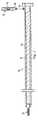
図2、図3Aおよび図3Bをここで参照すると、椎間空間S(図1)内への人工装置の埋込みを補助するためのアセンブリが、全体として符号20を付けられ、一実施形態では、位置合わせ器具22および付随する埋込み装置24を備えるように示されている。位置合わせ器具22は、ねじ、ケージ、関節インプラント全体などの様々な人工装置の埋込みを補助するために使用されてもよいことを理解されたい。一実施形態では、位置合わせ器具22は、全体的に直線状の形状であり、位置合わせ器具の長手方向軸によって画定されるX軸に沿って延びている。位置合わせ器具22は、器具のほぼ環状のハウジング28内に配置されたプランジャ部材26と、プランジャ部材26の近端部と一体に形成されたノブ30とを備える。このようにして、ノブ30の回転が、プランジャ部材26に回転を賦与するように構成される。ねじ山付き骨ねじ32などの固定装置が、さらに説明するようにプランジャ部材26から回転方向および平行移動方向の力を受けるように位置合わせ器具22の遠端部内に配置されている。一実施形態では、骨ねじ32は、鋼などのX線不透過性の材料で形成されている。本開示では、「近位」という用語は、位置合わせ器具20の、ほぼ外科医(図示せず)などの使用者側に向かう方向を称し、「遠位」という用語は、ほぼ患者(図示せず)側に向かう方向を称する。 Referring now to FIGS. 2, 3A and 3B, an assembly for assisting in the implantation of the prosthetic device in the intervertebral space S (FIG. 1) is generally designated 20 and, in one embodiment, An
一実施形態では、ハウジング28の内側の環状の表面34は、プランジャ部材26の対応するねじ山付き部分38を受けてそれと係合するねじ山付き部分36を備える。したがって、ノブ30を介してのプランジャ部材26の回転は、プランジャ部材をハウジング内で回転させるだけでなく、プランジャ部材をハウジング24を通って平行移動させる。図3Bに最もよく見られるように、プランジャ部材26の遠端部は、骨ねじ32の球形の頭部42と係合するように構成された、遠端部に形成された球状の溝40を備える。本実施例では、ハウジング28の遠端部は、骨ねじの頭部42をハウジング内に保持しながら、骨ねじ32のねじ山付き部分44がハウジングに対して回転することを許すように、直径が減少され、隅切りされている。 In one embodiment, the inner
位置合わせ器具22はまた、X線位置合わせを提供するように構成され、また、位置合わせ器具の近位の部分は、符号46によって全体的に示されているX線マーカーを収容するために位置合わせ器具の遠位の部分に対して直径が増加されている。一実施形態では、X線マーカー46は、1対のリング48、50を備える。リング48は、位置合わせ器具22の近位の部分内に配置され、したがって、近位の部分の直径内に嵌合するために対応する直径を有する。リング50は、位置合わせ器具20の遠位の部分内に配置され、したがって、遠位の部分の直径内に嵌合するために対応する直径を有する。同様に、リング48、50は、これから説明するように位置合わせを補助するために協働する。リング48、50は、また、金属などのX線撮影用材料で形成されてもよいことを理解されたい。リング48、50が、X様の形状を形成して、それによってこれも位置合わせを補助するように形成された金属ロッドなどの代替となるX線マーカーと交換されてもよいことをさらに理解されたい。 The
図2を再び参照すると、1対の締結アセンブリ52、54が、位置合わせ器具22を付随する埋込み装置24と動作可能に接続するために設けられている。一実施形態では、埋込みデバイス24は、すべての正当な目的のために参照によって本明細書に組み込まれる米国特許出願第10/430,473号に記載された器具とほぼ同様である。内側締結アセンブリ52は(位置合わせ器具22に対して)、位置合わせ器具22と滑動自在に係合するように構成され、それ自体、滑動自在な係合を容易にするために調節可能な締結部分57を通って画定された溝56を備える。内側締結アセンブリ52は、内側締結アセンブリ52を位置合わせ器具22に解放可能に固定するように構成された、コネクタ58を備える。本実施例では、コネクタ58は、締結部分57と接触するように内側締結アセンブリ52を通って螺合し、このようにして締結部分を位置合わせ器具22と係合または分離するように駆動されることができる。したがって、内側締結アセンブリ52は、位置合わせ器具22によって画定されるX軸に沿って調節可能であり、さらに、内側締結アセンブリ52の所望の位置への調節の際、位置合わせ器具に固定されることができる。 Referring again to FIG. 2, a pair of
外側締結アセンブリ54(位置合わせ器具22に対して)が、内側締結アセンブリ52と滑動自在に係合するように構成される。一実施形態では、外側締結アセンブリ54は、外側締結アセンブリが内側締結アセンブリのフランジ部分62を介して内側締結アセンブリ52と滑動自在に係合することを許すように、その中に画定された溝60を備える。したがって、外側締結アセンブリ54は、Y軸に沿って内側締結アセンブリ52に対して調節可能である。たとえば、図2の実施形態では、外側締結アセンブリ54は、位置合わせ器具22に対して横方向に調節可能である。外側締結アセンブリ54はコネクタ64をさらに備え、コネクタは、外側締結アセンブリ54を内側締結アセンブリ52に解放可能に固定するように構成される。本実施例では、コネクタ64は、外側締結アセンブリ54を通ってねじ込まれ、このようにして内側締結アセンブリ52と係合または分離するように駆動されることができる。 Outer fastening assembly 54 (relative to alignment tool 22) is configured to slidably engage inner fastening assembly 52. In one embodiment, the
理解できるように、内側締結アセンブリ52は、位置合わせ器具22の周りに回転自在である。このため、図2で見られるように横軸であるとして説明したが、Y軸の表示は、内側締結アセンブリ52の位置合わせ器具22に対する位置に応じて変化してもよい。たとえば、内側締結アセンブリ52は、埋込み装置24を、位置合わせ器具22と同じ水平面内に配置するために回転されることができる。この実施例では、外側締結アセンブリ54は、Y軸に沿ってさらに調節可能であり、Y軸は鉛直軸とみなされることになる。 As can be appreciated, the inner fastening assembly 52 is rotatable about the
外側締結アセンブリ54はさらに、外側締結アセンブリのそれぞれ1対の対応する締結部分70、72内に形成された1対の溝66、68を介して埋込み装置24(図4)を受けるように構成される。埋込み装置24は、埋込み装置が外側締結アセンブリ54に対して滑動自在であるように、溝66、68内に配置するように構成される。さらに、埋込み装置を所望の位置に調節する際に締結部分70を締結部分72に向かって進行させ、それによって埋込み装置24を外側締結アセンブリ52内に固定するために、追加のコネクタ74が外側締結アセンブリ54に付随している。本実施例では、コネクタ74は、締結部分70に付随するねじ山付きロッド(図示せず)に沿って調節可能であり、このようにして、締結部分70は、コネクタ74の調節を介して締結部分72のほうへ駆動されることができる。同様に、埋込み装置24は、埋込み装置の長手方向軸によって画定されるA軸に沿って調節可能である。もちろん、埋込み装置24は、外側締結アセンブリの内側締結アセンブリ52に対する様々な位置に対応するように調節するために、外側締結アセンブリ54内で回転されることができ、同様に、埋込み装置は、A軸の周りに回転可能である。 The
図4を参照すると、一実施形態では、80によって全体的に示される人工装置の椎間空間S内への挿入前に関連する埋込み装置24をそこから位置合わせするための固定点を設けるために、骨ねじ32が椎骨V1内に挿入されるように構成される。もちろん、骨ねじ32が別法として椎骨V2内に挿入されてもよい。X線透視装置、すなわちCアーム82が、位置合わせ器具22の配置をX線透視で補助するためにさらに設けられている。わかりやすくするために、人工装置80の挿入のために位置合わせ器具22を位置合わせする方法は、椎間空間Sへの前方/傾斜アプローチに関して説明される。しかし、位置合わせ手法は、一般的な意味で、側方アプローチを含む椎間空間への他のアプローチのために適用可能であることを理解されたい。 Referring to FIG. 4, in one embodiment, to provide a fixation point for aligning the associated
動作中、引き続き図4を参照すると、位置合わせ器具22が、前方/傾斜挿入アプローチに対応するようにCアーム82を椎骨V1、V2を直接前方に見て配置することによってX線透視の補助で位置合わせされる。位置合わせ器具22が次に、骨ねじ32が上側椎骨V1と係合するように配置される。一実施形態では、骨ねじ32は、上側椎骨V1の中線の比較的近くに配置される。しかし、骨ねじの上側椎骨に対する正確な配置は、重要でないことを理解されたい。適切な配置のとき、プランジャ部材26(図3A、3B)が、骨ねじを上側椎骨V1内へ動かすために骨ねじ32にあてて駆動され、それによって骨ねじの位置によって画定される固定された固定位置を提供する。 In operation, with continued reference to FIG. 4, the
位置合わせ器具22の近位の部分が、次に、Cアーム82に付随するモニター(図示せず)上で見たとき、X線マーカー46を骨ねじ32の球形の頭部42と位置合わせするように調節される。モニターを見ることによって決定された適切な位置合わせで、位置合わせ器具22が次に、プランジャ部材26を骨ねじ32にあててさらに進行させることによって定位置にロックされる。埋込み装置24が次に、外側締結アセンブリ54の溝66、68内に配置される。埋込み装置24の位置が次に、椎間空間Sの中心に対応するように調節され、所望の位置に達すると、埋込み装置の位置が、コネクタ64を内側締結アセンブリ52と係合させることによってロックされる。 The proximal portion of the
埋込み装置24は、椎間空間S内への埋込みのために人工装置80を適切に配置するためのA軸に沿ってさらに調節可能である。一実施形態では、適切な配置は、人工装置80を接触点に対して椎体V1、V2に近接して配置することを伴う。適切な配置のとき、埋込み装置24が、コネクタ74を外側締結アセンブリ54と係合させることによってA軸に沿ってロックされる。埋込み装置24が、次に、人工装置80を椎間空間S内へ挿入するために駆動される。 The
このようにして、上記で説明したプロセスおよび関連する機器が、最小のX線透視案内で人工装置80の位置合わせおよび埋込みを可能にする。ここで図5を参照すると、代替となる実施形態では、人工装置80の位置合わせおよび挿入が、代替となる位置合わせ器具90の使用を通じてX線透視案内なしで達成されることができる。位置合わせ器具90は、一実施形態では、X線マーカーおよびCアームX線透視装置の必要性を除去する、気泡水準装置92を備える。位置合わせ器具90は、以下で説明する特徴を除いて位置合わせ器具22とほぼ同様であり、位置合わせ器具22の特徴とほぼ同様である位置合わせ器具90の特徴は、同じ参照符号を与えられている。 In this way, the processes and associated equipment described above allow alignment and implantation of the prosthetic device 80 with minimal fluoroscopic guidance. Referring now to FIG. 5, in an alternative embodiment, alignment and insertion of the prosthetic device 80 can be accomplished without fluoroscopic guidance through the use of an
位置合わせ器具90は、それを通ってプランジャ部材26が骨ねじ32と係合するために移動するように構成されるほぼ一様なハウジング94を備える。位置合わせ器具90は、ねじ付き接続部などを介して、任意の従来の方式で位置合わせ機器90と接触する気泡水準器92とともに使用するように構成される。たとえば、気泡水準器92は、位置合わせ器具90内に画定されたねじ付き受け部98と係合するためのねじ付きコネクタ96を備えてもよい。もちろん、いくつかの実施形態では、気泡水準器92が位置合わせ器具90と一体に形成されてもよい。気泡水準器92は、多くの点で従来通りであり、したがって流体を保持するために気泡水準器を通って画定された空洞(図示せず)、および流体を見るための透明部分100を備える。 The
動作中、位置合わせ器具90は、椎間空間S内へ挿入するために人工装置80を位置合わせするために、内側および外側締結アセンブリ52、54とともに使用される。位置合わせ器具90を固定する前に、患者(図示せず)が、まず手術台(図示せず)に対してほぼ90°の角度で位置合わせされる。患者を適切に配置し、次に、位置合わせ器具90の骨ねじ32が、固定点を提供するために上側椎骨V1内へ挿入される。次に、気泡水準器92が中立位置を示すまで位置合わせ器具90を調節することによって、位置合わせ器具90の近位の、すなわち自由な端部が、適切な位置に位置合わせされる。 In operation, the
本開示は、いくつかの好ましい実施形態に対して説明されてきた。本開示を読んだ後当業者に明らかになる改良および修正は、適用例の精神および範囲内にあるとみなされる。たとえば、位置合わせプロセス中、プローブが、埋込み装置24の配置の前に位置合わせ器具22、90とともに使用されてもよい。このようにして、椎間空間Sに対する様々な器具の適切な配置が、さらに確実にされる。また、前方傾斜アプローチを参照にして説明されているが、上記で説明した方法および器具は、様々な挿入アプローチで使用されてもよいことを理解されたい。さらに、固定装置は骨ねじとして説明されているが、様々な固定装置が、位置合わせ器具22、90とともに使用されてもよい。 The present disclosure has been described with respect to several preferred embodiments. Improvements and modifications that will become apparent to those skilled in the art after reading this disclosure are deemed to be within the spirit and scope of the application. For example, during the alignment process, the probe may be used with
したがって、いくつかの修正、変更および代替が、前述の開示で企図されており、いくつかの例では、本開示のいくつかの特徴が、他の特徴をそれに対応して使用することなく採用されることを理解されたい。「内側」、「外側」、「近位」、「遠位」などのすべての空間的な用語は、例示の目的のために過ぎず、本開示の範囲内で様々であってよいことも理解されたい。したがって、添付の特許請求の範囲は、広範囲に、本開示の範囲に一致するように解釈されることが理解されよう。 Accordingly, several modifications, changes and alternatives are contemplated in the foregoing disclosure, and in some examples, some features of the present disclosure are employed without correspondingly using other features. Please understand that. It is also understood that all spatial terms such as “inner”, “outer”, “proximal”, “distal” are for exemplary purposes only and may vary within the scope of this disclosure. I want to be. Accordingly, it is to be understood that the appended claims are construed broadly to be consistent with the scope of the disclosure.
Claims (29)
Translated fromJapanese環状のハウジングと、
前記環状のハウジング内に配置され、それを通って移動するように構成されたプランジャ部材と、
前記環状のハウジング内に部分的に配置された固定装置と、
を備え、前記固定装置が前記プランジャ部材によって駆動されるように構成される、椎間空間内に挿入するための人工装置を位置合わせするのを補助する器具。An instrument that assists in aligning a prosthetic device for insertion into an intervertebral space,
An annular housing;
A plunger member disposed within the annular housing and configured to move therethrough;
A securing device partially disposed within the annular housing;
An instrument for assisting in aligning a prosthetic device for insertion into an intervertebral space, wherein the fixation device is configured to be driven by the plunger member.
位置合わせ器具を椎間空間に隣接して配置された椎体内に固定する手段と、
埋込み装置を前記位置合わせ器具と動作可能に接続する手段であって、前記人工装置が前記埋込み装置上に配置される、手段と、
前記人工装置を前記椎間空間と隣接して配置するために前記埋込み装置を調節する手段と、
を備える、椎間空間内へ挿入するための人工装置を位置合わせするためのアセンブリ。An assembly for aligning a prosthetic device for insertion into an intervertebral space,
Means for securing the alignment device within the vertebral body located adjacent to the intervertebral space;
Means for operably connecting an implantable device with the alignment device, wherein the prosthetic device is disposed on the implantable device;
Means for adjusting the implant device to position the prosthetic device adjacent to the intervertebral space;
An assembly for aligning a prosthetic device for insertion into an intervertebral space.
位置合わせ器具と、
前記位置合わせ器具と滑動自在に係合された第1の締結アセンブリと、
前記第1の締結アセンブリと滑動自在に係合された第2の締結アセンブリと、
前記第2の締結アセンブリと滑動自在に係合された埋込み装置と
を備え、前記埋込み装置が、人工装置をその上に維持するように構成される、椎間空間内へ挿入するための人工装置を位置合わせするためのアセンブリ。An assembly for aligning a prosthetic device for insertion into an intervertebral space,
An alignment tool;
A first fastening assembly slidably engaged with the alignment tool;
A second fastening assembly slidably engaged with the first fastening assembly;
An artificial device for insertion into an intervertebral space comprising an implantable device slidably engaged with the second fastening assembly, wherein the implantable device is configured to maintain the prosthetic device thereon Assembly for aligning.
そこから延びている固定装置を有する位置合わせ器具を提供するステップと、
前記固定装置を椎間空間に隣接して配置されている椎体と係合させるステップと、
前記位置合わせ器具を前記椎間空間に対して位置合わせするステップと、
前記固定装置を前記椎体内へ動かすステップと、
前記位置合わせ器具と動作可能に接続された締結アセンブリを介して前記位置合わせ器具に隣接して埋込み装置を提供し、前記埋込み装置が前記人工装置をその遠端部に保持するステップと、
を含む、椎間空間内へ挿入するために人工装置を位置合わせするための方法。A method for aligning a prosthetic device for insertion into an intervertebral space comprising:
Providing an alignment tool having a fixation device extending therefrom;
Engaging the fixation device with a vertebral body disposed adjacent to the intervertebral space;
Aligning the alignment device relative to the intervertebral space;
Moving the fixation device into the vertebral body;
Providing an implant device adjacent to the alignment device via a fastening assembly operably connected to the alignment device, the implant device holding the prosthetic device at its distal end;
A method for aligning a prosthetic device for insertion into an intervertebral space.
Applications Claiming Priority (3)
| Application Number | Priority Date | Filing Date | Title |
|---|---|---|---|
| US44696303P | 2003-02-12 | 2003-02-12 | |
| US43047303A | 2003-05-06 | 2003-05-06 | |
| PCT/US2004/004534WO2004071360A2 (en) | 2003-02-12 | 2004-02-12 | Instruments and methods for aligning implants for insertion |
Publications (1)
| Publication Number | Publication Date |
|---|---|
| JP2006517460Atrue JP2006517460A (en) | 2006-07-27 |
Family
ID=32871781
Family Applications (2)
| Application Number | Title | Priority Date | Filing Date |
|---|---|---|---|
| JP2006503517APendingJP2006517456A (en) | 2003-02-12 | 2004-02-12 | Fusion prosthesis for insertion into the intervertebral space |
| JP2006503618APendingJP2006517460A (en) | 2003-02-12 | 2004-02-12 | Apparatus and method for aligning an implant for insertion |
Family Applications Before (1)
| Application Number | Title | Priority Date | Filing Date |
|---|---|---|---|
| JP2006503517APendingJP2006517456A (en) | 2003-02-12 | 2004-02-12 | Fusion prosthesis for insertion into the intervertebral space |
Country Status (7)
| Country | Link |
|---|---|
| EP (2) | EP1596777A2 (en) |
| JP (2) | JP2006517456A (en) |
| AT (1) | ATE505156T1 (en) |
| AU (2) | AU2004211984A1 (en) |
| CA (2) | CA2515767A1 (en) |
| DE (1) | DE602004032216D1 (en) |
| WO (1) | WO2004071346A2 (en) |
Families Citing this family (3)
| Publication number | Priority date | Publication date | Assignee | Title |
|---|---|---|---|---|
| US8764832B2 (en) | 2005-09-26 | 2014-07-01 | Warsaw Orhtopedic, Inc. | Anterior hybrid implant |
| CN101272750A (en) | 2005-09-26 | 2008-09-24 | 华沙整形外科股份有限公司 | Transforaminal hybrid implant |
| CA2623448A1 (en)* | 2005-09-26 | 2007-03-29 | Frank J. Schwab | Hybrid intervertebral spinal fusion implant |
Citations (5)
| Publication number | Priority date | Publication date | Assignee | Title |
|---|---|---|---|---|
| US5484440A (en)* | 1992-11-03 | 1996-01-16 | Zimmer, Inc. | Bone screw and screwdriver |
| US5649931A (en)* | 1996-01-16 | 1997-07-22 | Zimmer, Inc. | Orthopaedic apparatus for driving and/or removing a bone screw |
| WO1998017208A2 (en)* | 1996-10-22 | 1998-04-30 | Surgical Dynamics, Inc. | Apparatus for fusing adjacent bone structures |
| US20010021853A1 (en)* | 2000-03-10 | 2001-09-13 | Richard Wolf Gmbh | Surgical instrument for applying implants |
| JP2002017761A (en)* | 2000-05-08 | 2002-01-22 | Depuy Acromed Inc | Medical installing instrument |
Family Cites Families (4)
| Publication number | Priority date | Publication date | Assignee | Title |
|---|---|---|---|---|
| US5591235A (en)* | 1995-03-15 | 1997-01-07 | Kuslich; Stephen D. | Spinal fixation device |
| FR2742653B1 (en)* | 1995-12-21 | 1998-02-27 | Colorado | INTERSOMATIC VERTEBRAL CAGE |
| AU2001275253A1 (en)* | 2000-06-05 | 2001-12-17 | Laser Fire | Orthopedic implant and method of making metal articles |
| ATE334644T1 (en)* | 2000-10-11 | 2006-08-15 | Michael D Mason | INTEGRATED FUSION DEVICE |
- 2004
- 2004-02-12AUAU2004211984Apatent/AU2004211984A1/ennot_activeAbandoned
- 2004-02-12CACA002515767Apatent/CA2515767A1/ennot_activeAbandoned
- 2004-02-12JPJP2006503517Apatent/JP2006517456A/enactivePending
- 2004-02-12ATAT04710664Tpatent/ATE505156T1/ennot_activeIP Right Cessation
- 2004-02-12DEDE602004032216Tpatent/DE602004032216D1/ennot_activeExpired - Lifetime
- 2004-02-12EPEP04710719Apatent/EP1596777A2/ennot_activeWithdrawn
- 2004-02-12WOPCT/US2004/004109patent/WO2004071346A2/enactiveApplication Filing
- 2004-02-12EPEP04710664Apatent/EP1596772B1/ennot_activeExpired - Lifetime
- 2004-02-12JPJP2006503618Apatent/JP2006517460A/enactivePending
- 2004-02-12CACA002515646Apatent/CA2515646A1/ennot_activeAbandoned
- 2004-02-12AUAU2004212017Apatent/AU2004212017A1/ennot_activeAbandoned
Patent Citations (5)
| Publication number | Priority date | Publication date | Assignee | Title |
|---|---|---|---|---|
| US5484440A (en)* | 1992-11-03 | 1996-01-16 | Zimmer, Inc. | Bone screw and screwdriver |
| US5649931A (en)* | 1996-01-16 | 1997-07-22 | Zimmer, Inc. | Orthopaedic apparatus for driving and/or removing a bone screw |
| WO1998017208A2 (en)* | 1996-10-22 | 1998-04-30 | Surgical Dynamics, Inc. | Apparatus for fusing adjacent bone structures |
| US20010021853A1 (en)* | 2000-03-10 | 2001-09-13 | Richard Wolf Gmbh | Surgical instrument for applying implants |
| JP2002017761A (en)* | 2000-05-08 | 2002-01-22 | Depuy Acromed Inc | Medical installing instrument |
Also Published As
| Publication number | Publication date |
|---|---|
| DE602004032216D1 (en) | 2011-05-26 |
| ATE505156T1 (en) | 2011-04-15 |
| WO2004071346A2 (en) | 2004-08-26 |
| WO2004071346A3 (en) | 2004-10-21 |
| EP1596777A2 (en) | 2005-11-23 |
| CA2515767A1 (en) | 2004-08-26 |
| AU2004212017A1 (en) | 2004-08-26 |
| AU2004211984A1 (en) | 2004-08-26 |
| EP1596772A2 (en) | 2005-11-23 |
| EP1596772B1 (en) | 2011-04-13 |
| CA2515646A1 (en) | 2004-08-26 |
| JP2006517456A (en) | 2006-07-27 |
Similar Documents
| Publication | Publication Date | Title |
|---|---|---|
| US20040220567A1 (en) | Instruments and methods for aligning implants for insertion | |
| US6949105B2 (en) | Method and apparatus for stereotactic implantation | |
| AU2014274748B2 (en) | Patient-matched apparatus and methods for performing surgical procedures | |
| US8852210B2 (en) | Rigidly guided implant placement | |
| JP5744874B2 (en) | Improved hip fracture nail system | |
| EP1807008B1 (en) | Instrument for the insertion and alignment of an intervertebral implant | |
| US20100004747A1 (en) | Trans-Vertebral and Intra-Vertebral Plate and Fusion Cage Device for Spinal Interbody Fusion and Method of Operation | |
| US20110202094A1 (en) | Trans-polyaxial screw | |
| US11944326B2 (en) | Systems and methods for transcorporeal microdecompression | |
| WO2006105070A1 (en) | X-ray and fluoroscopic visualization slots | |
| US8366718B2 (en) | Preparation device for preparing an intervertebral disc compartment | |
| US11771477B2 (en) | Methods and instruments for performing leveraged reduction during single position spine surgery | |
| US20060276800A1 (en) | Intervertebral disc replacement and surgical instruments therefor | |
| US20110196373A1 (en) | Bone preparation device | |
| WO2004071360A2 (en) | Instruments and methods for aligning implants for insertion | |
| EP2065016A1 (en) | Trans-vertebral and intra-vertebral plate and fusion cage device for spinal interbody fusion and method of operation | |
| JP2019521806A (en) | Instrument assembly used in hip replacement surgery | |
| Kang et al. | Computed tomography–guided percutaneous facet screw fixation in the lumbar spine | |
| US20210153857A1 (en) | Lateral access system and method of use | |
| JP2006517460A (en) | Apparatus and method for aligning an implant for insertion | |
| US20230338074A1 (en) | Guided systems and methods for implanting fasteners into tissue | |
| US10390843B1 (en) | Trajectory and aiming guide for use with fluoroscopy |
Legal Events
| Date | Code | Title | Description |
|---|---|---|---|
| A711 | Notification of change in applicant | Free format text:JAPANESE INTERMEDIATE CODE: A712 Effective date:20061011 | |
| A621 | Written request for application examination | Free format text:JAPANESE INTERMEDIATE CODE: A621 Effective date:20070123 | |
| A131 | Notification of reasons for refusal | Free format text:JAPANESE INTERMEDIATE CODE: A131 Effective date:20100106 | |
| A601 | Written request for extension of time | Free format text:JAPANESE INTERMEDIATE CODE: A601 Effective date:20100405 | |
| A602 | Written permission of extension of time | Free format text:JAPANESE INTERMEDIATE CODE: A602 Effective date:20100412 | |
| A02 | Decision of refusal | Free format text:JAPANESE INTERMEDIATE CODE: A02 Effective date:20100706 |