JP2006514382A - System and method for monitoring the external environment of a vehicle - Google Patents
System and method for monitoring the external environment of a vehicleDownload PDFInfo
- Publication number
- JP2006514382A JP2006514382AJP2005507726AJP2005507726AJP2006514382AJP 2006514382 AJP2006514382 AJP 2006514382AJP 2005507726 AJP2005507726 AJP 2005507726AJP 2005507726 AJP2005507726 AJP 2005507726AJP 2006514382 AJP2006514382 AJP 2006514382A
- Authority
- JP
- Japan
- Prior art keywords
- capture device
- vehicle
- detection means
- monitoring area
- trajectory
- Prior art date
- Legal status (The legal status is an assumption and is not a legal conclusion. Google has not performed a legal analysis and makes no representation as to the accuracy of the status listed.)
- Pending
Links
- 238000012544monitoring processMethods0.000titleclaimsabstractdescription44
- 238000000034methodMethods0.000titleclaimsabstractdescription33
- 238000001514detection methodMethods0.000claimsabstractdescription57
- 238000012545processingMethods0.000claimsdescription16
- 238000004458analytical methodMethods0.000claimsdescription11
- 230000008859changeEffects0.000claimsdescription11
- 238000002604ultrasonographyMethods0.000claimsdescription10
- 230000005855radiationEffects0.000claimsdescription6
- 230000010349pulsationEffects0.000claimsdescription2
- 230000000153supplemental effectEffects0.000abstract1
- 230000006870functionEffects0.000description6
- 230000001133accelerationEffects0.000description4
- 230000006399behaviorEffects0.000description2
- 238000005516engineering processMethods0.000description2
- 230000000903blocking effectEffects0.000description1
- 238000004422calculation algorithmMethods0.000description1
- 230000000295complement effectEffects0.000description1
- 230000007613environmental effectEffects0.000description1
- 238000005259measurementMethods0.000description1
- 238000012986modificationMethods0.000description1
- 230000004048modificationEffects0.000description1
- 230000003287optical effectEffects0.000description1
- 238000012360testing methodMethods0.000description1
Images


Classifications
- G—PHYSICS
- G08—SIGNALLING
- G08G—TRAFFIC CONTROL SYSTEMS
- G08G1/00—Traffic control systems for road vehicles
- G08G1/16—Anti-collision systems
- G08G1/161—Decentralised systems, e.g. inter-vehicle communication
- G—PHYSICS
- G01—MEASURING; TESTING
- G01S—RADIO DIRECTION-FINDING; RADIO NAVIGATION; DETERMINING DISTANCE OR VELOCITY BY USE OF RADIO WAVES; LOCATING OR PRESENCE-DETECTING BY USE OF THE REFLECTION OR RERADIATION OF RADIO WAVES; ANALOGOUS ARRANGEMENTS USING OTHER WAVES
- G01S13/00—Systems using the reflection or reradiation of radio waves, e.g. radar systems; Analogous systems using reflection or reradiation of waves whose nature or wavelength is irrelevant or unspecified
- G01S13/88—Radar or analogous systems specially adapted for specific applications
- G01S13/93—Radar or analogous systems specially adapted for specific applications for anti-collision purposes
- G01S13/931—Radar or analogous systems specially adapted for specific applications for anti-collision purposes of land vehicles
- G—PHYSICS
- G08—SIGNALLING
- G08G—TRAFFIC CONTROL SYSTEMS
- G08G1/00—Traffic control systems for road vehicles
- G08G1/16—Anti-collision systems
- G08G1/161—Decentralised systems, e.g. inter-vehicle communication
- G08G1/163—Decentralised systems, e.g. inter-vehicle communication involving continuous checking
- B—PERFORMING OPERATIONS; TRANSPORTING
- B60—VEHICLES IN GENERAL
- B60R—VEHICLES, VEHICLE FITTINGS, OR VEHICLE PARTS, NOT OTHERWISE PROVIDED FOR
- B60R2300/00—Details of viewing arrangements using cameras and displays, specially adapted for use in a vehicle
- B60R2300/10—Details of viewing arrangements using cameras and displays, specially adapted for use in a vehicle characterised by the type of camera system used
- B60R2300/106—Details of viewing arrangements using cameras and displays, specially adapted for use in a vehicle characterised by the type of camera system used using night vision cameras
- B—PERFORMING OPERATIONS; TRANSPORTING
- B60—VEHICLES IN GENERAL
- B60R—VEHICLES, VEHICLE FITTINGS, OR VEHICLE PARTS, NOT OTHERWISE PROVIDED FOR
- B60R2300/00—Details of viewing arrangements using cameras and displays, specially adapted for use in a vehicle
- B60R2300/30—Details of viewing arrangements using cameras and displays, specially adapted for use in a vehicle characterised by the type of image processing
- B60R2300/301—Details of viewing arrangements using cameras and displays, specially adapted for use in a vehicle characterised by the type of image processing combining image information with other obstacle sensor information, e.g. using RADAR/LIDAR/SONAR sensors for estimating risk of collision
- B—PERFORMING OPERATIONS; TRANSPORTING
- B60—VEHICLES IN GENERAL
- B60R—VEHICLES, VEHICLE FITTINGS, OR VEHICLE PARTS, NOT OTHERWISE PROVIDED FOR
- B60R2300/00—Details of viewing arrangements using cameras and displays, specially adapted for use in a vehicle
- B60R2300/30—Details of viewing arrangements using cameras and displays, specially adapted for use in a vehicle characterised by the type of image processing
- B60R2300/304—Details of viewing arrangements using cameras and displays, specially adapted for use in a vehicle characterised by the type of image processing using merged images, e.g. merging camera image with stored images
- B60R2300/305—Details of viewing arrangements using cameras and displays, specially adapted for use in a vehicle characterised by the type of image processing using merged images, e.g. merging camera image with stored images merging camera image with lines or icons
- B—PERFORMING OPERATIONS; TRANSPORTING
- B60—VEHICLES IN GENERAL
- B60R—VEHICLES, VEHICLE FITTINGS, OR VEHICLE PARTS, NOT OTHERWISE PROVIDED FOR
- B60R2300/00—Details of viewing arrangements using cameras and displays, specially adapted for use in a vehicle
- B60R2300/80—Details of viewing arrangements using cameras and displays, specially adapted for use in a vehicle characterised by the intended use of the viewing arrangement
- B60R2300/802—Details of viewing arrangements using cameras and displays, specially adapted for use in a vehicle characterised by the intended use of the viewing arrangement for monitoring and displaying vehicle exterior blind spot views
- B—PERFORMING OPERATIONS; TRANSPORTING
- B60—VEHICLES IN GENERAL
- B60R—VEHICLES, VEHICLE FITTINGS, OR VEHICLE PARTS, NOT OTHERWISE PROVIDED FOR
- B60R2300/00—Details of viewing arrangements using cameras and displays, specially adapted for use in a vehicle
- B60R2300/80—Details of viewing arrangements using cameras and displays, specially adapted for use in a vehicle characterised by the intended use of the viewing arrangement
- B60R2300/8053—Details of viewing arrangements using cameras and displays, specially adapted for use in a vehicle characterised by the intended use of the viewing arrangement for bad weather conditions or night vision
- B—PERFORMING OPERATIONS; TRANSPORTING
- B60—VEHICLES IN GENERAL
- B60R—VEHICLES, VEHICLE FITTINGS, OR VEHICLE PARTS, NOT OTHERWISE PROVIDED FOR
- B60R2300/00—Details of viewing arrangements using cameras and displays, specially adapted for use in a vehicle
- B60R2300/80—Details of viewing arrangements using cameras and displays, specially adapted for use in a vehicle characterised by the intended use of the viewing arrangement
- B60R2300/8086—Details of viewing arrangements using cameras and displays, specially adapted for use in a vehicle characterised by the intended use of the viewing arrangement for vehicle path indication
- B—PERFORMING OPERATIONS; TRANSPORTING
- B60—VEHICLES IN GENERAL
- B60W—CONJOINT CONTROL OF VEHICLE SUB-UNITS OF DIFFERENT TYPE OR DIFFERENT FUNCTION; CONTROL SYSTEMS SPECIALLY ADAPTED FOR HYBRID VEHICLES; ROAD VEHICLE DRIVE CONTROL SYSTEMS FOR PURPOSES NOT RELATED TO THE CONTROL OF A PARTICULAR SUB-UNIT
- B60W2554/00—Input parameters relating to objects
- G—PHYSICS
- G01—MEASURING; TESTING
- G01S—RADIO DIRECTION-FINDING; RADIO NAVIGATION; DETERMINING DISTANCE OR VELOCITY BY USE OF RADIO WAVES; LOCATING OR PRESENCE-DETECTING BY USE OF THE REFLECTION OR RERADIATION OF RADIO WAVES; ANALOGOUS ARRANGEMENTS USING OTHER WAVES
- G01S13/00—Systems using the reflection or reradiation of radio waves, e.g. radar systems; Analogous systems using reflection or reradiation of waves whose nature or wavelength is irrelevant or unspecified
- G01S13/88—Radar or analogous systems specially adapted for specific applications
- G01S13/93—Radar or analogous systems specially adapted for specific applications for anti-collision purposes
- G01S13/931—Radar or analogous systems specially adapted for specific applications for anti-collision purposes of land vehicles
- G01S2013/9315—Monitoring blind spots
- G—PHYSICS
- G01—MEASURING; TESTING
- G01S—RADIO DIRECTION-FINDING; RADIO NAVIGATION; DETERMINING DISTANCE OR VELOCITY BY USE OF RADIO WAVES; LOCATING OR PRESENCE-DETECTING BY USE OF THE REFLECTION OR RERADIATION OF RADIO WAVES; ANALOGOUS ARRANGEMENTS USING OTHER WAVES
- G01S13/00—Systems using the reflection or reradiation of radio waves, e.g. radar systems; Analogous systems using reflection or reradiation of waves whose nature or wavelength is irrelevant or unspecified
- G01S13/88—Radar or analogous systems specially adapted for specific applications
- G01S13/93—Radar or analogous systems specially adapted for specific applications for anti-collision purposes
- G01S13/931—Radar or analogous systems specially adapted for specific applications for anti-collision purposes of land vehicles
- G01S2013/932—Radar or analogous systems specially adapted for specific applications for anti-collision purposes of land vehicles using own vehicle data, e.g. ground speed, steering wheel direction
- G—PHYSICS
- G01—MEASURING; TESTING
- G01S—RADIO DIRECTION-FINDING; RADIO NAVIGATION; DETERMINING DISTANCE OR VELOCITY BY USE OF RADIO WAVES; LOCATING OR PRESENCE-DETECTING BY USE OF THE REFLECTION OR RERADIATION OF RADIO WAVES; ANALOGOUS ARRANGEMENTS USING OTHER WAVES
- G01S13/00—Systems using the reflection or reradiation of radio waves, e.g. radar systems; Analogous systems using reflection or reradiation of waves whose nature or wavelength is irrelevant or unspecified
- G01S13/88—Radar or analogous systems specially adapted for specific applications
- G01S13/93—Radar or analogous systems specially adapted for specific applications for anti-collision purposes
- G01S13/931—Radar or analogous systems specially adapted for specific applications for anti-collision purposes of land vehicles
- G01S2013/9323—Alternative operation using light waves
- G—PHYSICS
- G01—MEASURING; TESTING
- G01S—RADIO DIRECTION-FINDING; RADIO NAVIGATION; DETERMINING DISTANCE OR VELOCITY BY USE OF RADIO WAVES; LOCATING OR PRESENCE-DETECTING BY USE OF THE REFLECTION OR RERADIATION OF RADIO WAVES; ANALOGOUS ARRANGEMENTS USING OTHER WAVES
- G01S13/00—Systems using the reflection or reradiation of radio waves, e.g. radar systems; Analogous systems using reflection or reradiation of waves whose nature or wavelength is irrelevant or unspecified
- G01S13/88—Radar or analogous systems specially adapted for specific applications
- G01S13/93—Radar or analogous systems specially adapted for specific applications for anti-collision purposes
- G01S13/931—Radar or analogous systems specially adapted for specific applications for anti-collision purposes of land vehicles
- G01S2013/9324—Alternative operation using ultrasonic waves
- G—PHYSICS
- G01—MEASURING; TESTING
- G01S—RADIO DIRECTION-FINDING; RADIO NAVIGATION; DETERMINING DISTANCE OR VELOCITY BY USE OF RADIO WAVES; LOCATING OR PRESENCE-DETECTING BY USE OF THE REFLECTION OR RERADIATION OF RADIO WAVES; ANALOGOUS ARRANGEMENTS USING OTHER WAVES
- G01S13/00—Systems using the reflection or reradiation of radio waves, e.g. radar systems; Analogous systems using reflection or reradiation of waves whose nature or wavelength is irrelevant or unspecified
- G01S13/88—Radar or analogous systems specially adapted for specific applications
- G01S13/93—Radar or analogous systems specially adapted for specific applications for anti-collision purposes
- G01S13/931—Radar or analogous systems specially adapted for specific applications for anti-collision purposes of land vehicles
- G01S2013/9327—Sensor installation details
- G01S2013/93274—Sensor installation details on the side of the vehicles
Landscapes
- Physics & Mathematics (AREA)
- General Physics & Mathematics (AREA)
- Engineering & Computer Science (AREA)
- Radar, Positioning & Navigation (AREA)
- Remote Sensing (AREA)
- Electromagnetism (AREA)
- Computer Networks & Wireless Communication (AREA)
- Radar Systems Or Details Thereof (AREA)
- Traffic Control Systems (AREA)
- Gyroscopes (AREA)
Abstract
Translated fromJapaneseDescription
Translated fromJapanese 発明の範囲
この発明は、自動車の外部環境を監視するためのシステム及び方法、特に、リアビューミラーに適用可能なシステム及び方法に関する。このシステムは、監視エリア内に含まれる物体を表している外部の存在に関する情報を捕捉するためのデバイスを有している。このデバイスは、少なくとも軌跡検出用手段と組み合わさって動作して、車両の軌跡に応じて前記監視エリアを変更する。The present invention relates to a system and method for monitoring the external environment of an automobile, and more particularly to a system and method applicable to a rear view mirror. The system has a device for capturing information about an external presence representing an object contained within the surveillance area. This device operates in combination with at least a track detection means, and changes the monitoring area according to the vehicle track.
発明の背景
自動車のドライバに視野の死角が存在するということは、この死角に入ってくる他の乗り物と衝突する危険性があることを示している。このことは、車両に取り付けられているリアビューミラーが提供する視野によっては未だ満足に解決されていない。従って、前述した死角をカバーするための視野に関して様々な代替策が様々な技術に基づいて開発された。そのうちのあるものは、地球の磁界の歪みを検出する方式に基づくようなものなどであり、車両に非常に近い領域及び一般に側方の領域をカバーするために使用される。また、前述したドライバの車両に、通常は後方から、そして、かなり遠い距離から近づいてくる車両を検出するために使用されるものもある。これらの場合には、例えば、電気−光学式デバイスやレーダなど、様々なタイプのデバイスが必要になる。この発明において向上させようとしているのは、かなり遠い距離から近づいてくる車両を検出するために使用されるこのタイプのデバイスの動作である。BACKGROUND OF THE INVENTION The presence of a blind spot in a motor vehicle driver indicates the danger of colliding with other vehicles entering the blind spot. This has not been solved satisfactorily depending on the field of view provided by the rear view mirror attached to the vehicle. Accordingly, various alternatives have been developed based on various technologies with respect to the field of view to cover the aforementioned blind spots. Some of them are based on a method for detecting the distortion of the earth's magnetic field and are used to cover areas that are very close to the vehicle and generally to the side. Others are used to detect a vehicle approaching the driver vehicle described above, usually from the rear and from a far distance. In these cases, various types of devices are required, such as electro-optical devices and radars. What is sought to be improved in the present invention is the operation of this type of device used to detect vehicles approaching from a very long distance.
特許出願EP-A-0591743には、好ましくは、リアビューミラーのケーシングに取り付けられたCCD技術に基づいた電気−光学式センサによって、車両間の相対位置を検出するためのデバイスが開示されている。前記電気―光学式センサは車両の中央情報システムへ接続された電子処理ユニットと協働する。それは、処理された信号を中央情報システムへ送って、最終的に警告信号を発生する。このデバイスの目的は、このデバイスが設置されている車両のドライバに対して、近づいてきている車両との衝突の危険性を表す様々な信号(音、光など)を介して警告を与えることである。また、車両のエマージェンシライト又はその方向指示器を駆動することによって、近づいてくる車両のドライバにも衝突の危険性を警告するために、前記デバイスを使用する可能性についても述べられている。 Patent application EP-A-0591743 discloses a device for detecting the relative position between vehicles, preferably with an electro-optical sensor based on CCD technology mounted on the casing of the rearview mirror. Said electro-optical sensor cooperates with an electronic processing unit connected to the central information system of the vehicle. It sends the processed signal to the central information system and finally generates a warning signal. The purpose of this device is to alert the driver of the vehicle where it is installed via various signals (sound, light, etc.) that indicate the danger of a collision with an approaching vehicle. is there. It also describes the possibility of using the device to alert an approaching vehicle driver to the danger of a collision by driving the vehicle emergency light or its turn indicator.
同一出願人の特許出願WO-A-01/61371には、前述したものと類似した物体の存在を検出するためのデバイスが開示されている。しかし、この場合には、検出デバイスは電磁波の受信機及び光センサから構成されており、受信した電磁波を電気信号に変換する。この文献においては、デジタル化されるとともに事前に増幅された画像を取得して処理するときに、その後の測定法が特に参照されており、また、前述したデバイスによって発生されるものと類似の警告信号を発生するために用いられそうな様々な計算アルゴリズムが参照されている。 The same applicant's patent application WO-A-01 / 61371 discloses a device for detecting the presence of an object similar to that described above. However, in this case, the detection device includes an electromagnetic wave receiver and an optical sensor, and converts the received electromagnetic wave into an electrical signal. This document specifically refers to subsequent measurements when acquiring and processing digitized and pre-amplified images, and warnings similar to those generated by the aforementioned devices. Reference is made to various computational algorithms that are likely to be used to generate signals.
出された提案は誘導安全性(conduction security)に関して大きな前進を提供しており、それによって、これらのデバイスが設置された車両の乗員に対する多くの危険な状況を回避しているけれども、多くの場合において、これらのデバイスは前述した乗員を混乱させていることもまた事実である。というのは、危険でもない通常の運転状況が誤って解釈され、他の車両が危険な程度まで近づいているというように混同されて、デバイスが駆動されて多くの誤った警告を発生するからである。こうしたことは、これらのデバイスを設計するときに、車両が実際の運転状況において遭遇するような非定常的な環境や、前述したデバイスをそうした環境に対応させる複雑さに留意してこなかったという事実によって起こる。 The proposals that have been made offer great advances in terms of guidance security, thereby avoiding many dangerous situations for passengers in vehicles where these devices are installed, but in many cases It is also true that these devices are confusing the occupants described above. This is because normal driving situations that are not dangerous are misinterpreted and confused as other vehicles are approaching to a dangerous degree, and the device is driven to generate many false warnings. is there. This is due to the fact that when designing these devices, we have not been aware of the non-stationary environment that the vehicle will encounter in real driving situations or the complexity of adapting the aforementioned devices to that environment. Caused by.
特許US6226571は、車両の環境をモニタするためのデバイス、すなわち、車両のルート情報及び相対位置のみを介して、道路形状、例えば、道路の曲率半径などを予測することのできるデバイスを提案している。提案されているデバイスは、車両のまわりの物体の存在を検出して、予め決められた検出座標系におけるその物体の位置に関する情報を供給するためのレーダシステムと、検出された物体に基づいて、物体すなわち道路の上を走っている車両を分類し、それを他のタイプの物体と識別する車両識別デバイスとを有している。このデバイスは、また、レーダシステムの出力信号及び車両識別デバイスの出力信号に従って、走行する車両の位置及びルート情報に基づいて、道路の形状を予測するための道路形状予測デバイスも有している。前記文献によって提案されているデバイスは、従来のデバイスとは違って、より密接に実際の運転状況を考慮していて、従来のもの、この場合には、レーダと類似した検出システムを、速度センサや運転角度センサなどの他のタイプのセンサと組み合わせているけれども、前述した特許出願は本発明によって提案されているものは違う。というのは、前記特許においては、最終的な目標の一つは、できるだけ早くかつ現実的に、車両が走行している道路又は道の形状、特に、その曲率半径に関する形状を予測することだからである。従って、レーダや前記センサを介して得られた情報に基づいて前を行く車両との間に適切な距離を維持するために車両のアクセル及びブレーキを自動的に制御することや、さらには、その状況が危険であれば警告信号を発することは可能であるけれども、先の文献では、レーダシステムの検出エリアを修正又は調節するために、又は前記検出を何らかの形で向上させるために、道路の形状に関する情報をいずれかの時点で使用することには触れられていない。 Patent US6226571 proposes a device for monitoring the environment of a vehicle, that is, a device capable of predicting a road shape, for example, a radius of curvature of a road, only through vehicle route information and relative position. . The proposed device is based on a radar system for detecting the presence of an object around a vehicle and supplying information about the position of the object in a predetermined detection coordinate system, and on the detected object, It has a vehicle identification device that classifies objects or vehicles running on the road and identifies them from other types of objects. The device also includes a road shape prediction device for predicting the shape of the road based on the position of the traveling vehicle and the route information according to the output signal of the radar system and the output signal of the vehicle identification device. Unlike the conventional device, the device proposed by the above literature considers the actual driving situation more closely, and the conventional one, in this case, a detection system similar to the radar is replaced with a speed sensor. The above-mentioned patent application is different from that proposed by the present invention, although it is combined with other types of sensors, such as, and driving angle sensors. This is because, in the patent, one of the ultimate goals is to predict the shape of the road or road on which the vehicle is traveling, in particular the shape related to its radius of curvature, as soon as possible and realistically. is there. Therefore, it is possible to automatically control the accelerator and brake of the vehicle in order to maintain an appropriate distance from the preceding vehicle based on the information obtained through the radar and the sensor, Although it is possible to issue a warning signal if the situation is dangerous, in the previous literature the shape of the road is used to correct or adjust the detection area of the radar system or to improve the detection in some way. There is no mention of using information at any point in time.
従って、実際の運転状況において車両が遭遇する様々な環境に留意するとともに、死角内における物体の存在を検出するためのシステムに前記環境の別の系統の検出デバイスを付け加えることによって、物体の存在の検出を向上させ、ひいては、望ましくない誤ったアラームを避けるために、こうした種類のデバイスの動作に関する従来技術における欠点をカバーすることが必要である。
発明の簡単な説明
この発明は、自動車の外部環境の監視を行うためのシステム及び方法、特に、前記車両の外部リアビューミラーに適用が可能なシステム及び方法を提案している。このシステムは、少なくとも一つの死角をカバーしている予め決められた監視エリアにおいて、前述した車両と衝突しそうな物体の存在の検出に適用される。従って、このシステムは捕捉デバイスを有している。補足デバイスは、例えば、カメラなどの電気−光学式デバイスとしてのパッシブデバイス、あるいは、例えば、レーダシステム、赤外線システム又は超音波システムなどのアクティブデバイスから成る。この捕捉デバイスは、前記監視エリア内に含まれる物体を表している外部から捕捉される存在に関する画像又は情報のサンプルを取得するのに適しており、電子システムが捕捉デバイスを介して得られた信号を処置及び解析し、また、この解析の結果の関数として出力信号を発生する。BRIEF DESCRIPTION OF THE INVENTION The present invention proposes a system and method for monitoring the external environment of an automobile, in particular a system and method applicable to the external rear view mirror of the vehicle. This system is applied to the detection of the presence of an object that is likely to collide with a vehicle in a predetermined monitoring area covering at least one blind spot. The system therefore has a capture device. The supplementary device consists of a passive device as an electro-optical device such as a camera or an active device such as a radar system, an infrared system or an ultrasound system. This capture device is suitable for obtaining a sample of images or information relating to an externally captured presence representing an object contained within the monitoring area, the signal obtained by the electronic system via the capture device Are processed and analyzed, and an output signal is generated as a function of the result of this analysis.
誤った検出を回避して、車両の死角内における物体の存在をより現実的な形で検出するために、提案されたシステムは、軌跡検出用手段と、傾斜検出用手段とを有している。これらは、前記電子システムと協働し、前記検出デバイスを介して得られるとともに処理及び解析された信号の関数として、捕捉デバイスによる有効な監視エリアを変更する。この場合、例えば、カーブを運転しているときなどのように、別の車両に対する通常の運転状況がシステムによって危険であると考えられてしまうというような事実をドライバが心配する必要がなく、従って、システムの信頼性が向上する。 In order to avoid false detection and to detect the presence of an object in the blind spot of the vehicle in a more realistic manner, the proposed system has a trajectory detection means and a tilt detection means. . These cooperate with the electronic system to change the effective monitoring area by the capture device as a function of the signals obtained and processed and analyzed via the detection device. In this case, the driver does not have to worry about the fact that the normal driving situation for another vehicle would be considered dangerous by the system, for example when driving a curve, and therefore , Improve system reliability.
この発明は、捕捉デバイスによってカバーされる監視エリアの変更が上述したシステムを用いて行われるようにする方法も提案している。 The invention also proposes a method in which the change of the monitoring area covered by the capture device is made using the system described above.
この方法は、前記監視エリアの中に入ってくる物体の検出を行う段階と、この検出を表す信号を得る段階と、前記信号を処置、処理及び解析し、前記解析の結果として出力信号を発生する段階とを有している。この方法は、また、前記電子システムを介して、車両の軌道検出用手段及び傾斜検出用手段を組み合わせて、車両の軌道及び/又は傾斜において起こり得る変動の検出を行う段階と、軌道及び/又は傾斜における前記起こり得る変動を表す信号の処置、処理及び解析を行う段階と、前記変動を表す値の蓄積を行う段階と、それらを用いて、軌道及び/又は傾斜を、捕捉デバイスによってカバーされる対応監視エリアと関連付けるチャートを形成する段階とを有する。前記チャートは、電子システムによってアクセス可能であり、また、それによって使用され、予め決められた時点においてその車両が遭遇している正確な環境が前記検出手段によっていったんわかったときに、捕捉デバイスによってカバーされる監視エリアを変更するための必要な行動をとる。この行動は使用される捕捉デバイスのタイプに応じて様々である。 The method includes detecting an object entering the monitoring area, obtaining a signal representing the detection, treating, processing and analyzing the signal, and generating an output signal as a result of the analysis. And a stage of performing. The method also includes, via the electronic system, combining vehicle trajectory detection means and tilt detection means to detect possible variations in the vehicle trajectory and / or inclination; and Performing the processing, processing and analysis of signals representative of the possible variations in tilt, storing values representing the variations, and using them, the trajectory and / or tilt is covered by a capture device. Forming a chart associated with the corresponding monitoring area. The chart is accessible by the electronic system and is used by it and is covered by the capture device once the exact environment that the vehicle is encountering at a predetermined time is known by the detection means. Take the necessary actions to change the monitored area. This behavior varies depending on the type of capture device used.
上述したこの発明の特徴及び利点は、以下における一連の実施の形態によりさらに明らかになるであろう。これらの実施の形態のいくつかが添付図面に描かれているが、説明のためのものであると理解されるべきであり、発明を制限するものではない。 The above-described features and advantages of the present invention will become more apparent from the following series of embodiments. Some of these embodiments are illustrated in the accompanying drawings, but should be understood to be illustrative and not limiting.
いくつかの実施形態の詳細な説明
添付図面によれば、この発明によって提案されているシステムは、車両の外部環境の監視に使用され、特に、リアビューミラーに適用可能なものである。このシステムは、少なくとも一つの死角をカバーしている予め決められた監視エリア内において、前記車両と衝突しそうな物体の存在を検出するようになっている。このシステムは、前記監視エリア内に含まれる物体を表している外部から捕捉される存在に関する画像又は情報のサンプルを取得するのに適した捕捉デバイス1を有するタイプである。電子システム4(図4参照)は前述した捕捉デバイス1によって得られた第1の信号を処理及び解析するための少なくとも一つのシステムを有している。このシステムは前記解析の結果の関数として出力信号を発生する。これは、光、音などの信号を介して、監視エリア内における物体の存在をドライバに警告するか、又はより積極的な形では、ドライバによる急激な操作を避けるために、一例として、こうした状況のときに、ハンドルを振動させる(又はその抵抗トルクを増大させる)か、又は車両のドアを部分的にブロックすることによって、ドライバが車両から出るのをより困難にするか、又は危険な状況、従って、起こり得るドライブオーバ(drive over)を避けるために、車両から出るのにどのドアを使用するのがよいのかを指示する。DETAILED DESCRIPTION OF SOME EMBODIMENTS According to the accompanying drawings, the system proposed by the present invention is used for monitoring the external environment of a vehicle and is particularly applicable to a rear view mirror. The system is adapted to detect the presence of an object that is likely to collide with the vehicle within a predetermined surveillance area covering at least one blind spot. This system is of the type having a capture device 1 suitable for obtaining a sample of images or information relating to an externally captured presence representing objects contained within the monitoring area. The electronic system 4 (see FIG. 4) has at least one system for processing and analyzing the first signal obtained by the capture device 1 described above. This system generates an output signal as a function of the result of the analysis. This is an example of this situation in order to alert the driver of the presence of an object in the surveillance area via a signal such as light, sound, or, in a more aggressive manner, to avoid abrupt manipulation by the driver. When the driver makes it more difficult or dangerous for the driver to exit the vehicle by vibrating the handle (or increasing its resistance torque) or partially blocking the vehicle door, Thus, it indicates which door should be used to exit the vehicle to avoid possible drive over.
本発明者は、実際の運転状況においては、監視エリアがまっすぐなままである場合には、誤った検出が起き、危険な実際の状況の検出が見逃されるでろうということを述べた。そうした欠点を克服し、システムの有効性を向上させて、車両の死角内における物体の存在の検出をより現実的な形で行うようにするために、このシステムは、軌道検出用手段2と、それと組み合わせられる車両の傾斜検出用手段3とを有している。これらは電子システム4と協働して、軌道検出用手段2及び/又は傾斜検出用手段3を介して得られるとともに処理及び解析された第2及び第3の信号の関数として、捕捉デバイス1によってカバーされる監視エリアを変更又は調節する。 The inventor has stated that in actual driving situations, if the monitoring area remains straight, false detections will occur and detection of dangerous actual situations will be missed. In order to overcome such drawbacks and improve the effectiveness of the system so that the detection of the presence of an object in the blind spot of the vehicle is performed in a more realistic manner, the system comprises a trajectory detection means 2, It has a vehicle inclination detecting means 3 combined therewith. These in cooperation with the electronic system 4 are obtained by the acquisition device 1 as a function of the second and third signals obtained and processed and analyzed via the trajectory detection means 2 and / or the tilt detection means 3. Change or adjust the coverage area covered.
これらはすべて、図1及び図2を見れば、よりよく理解されよう。これらの図面には、前述した実際の運転状況の二つが示されており、両方とも左カーブの車両軌道を表しているが、図2においては図1におけるよりも曲率半径がずっと小さい。両方の図面には、捕捉デバイス1によってカバーされなければならないエリアが示されているが、図からわかるように、一方の場合は他方の場合に比べて非常に異なっている。このことから、例えば、図1に示されているエリアをカバーしている図2において、追い越そうとしている車両を検出しようとすると、前記検出から簡単に逃げてしまう可能性のあることがわかる。しかし、この問題はそのエリアを任意のケースに適合させることによって解決される。 All of these will be better understood with reference to FIGS. In these drawings, two of the actual driving situations mentioned above are shown, both representing a left-curved vehicle track, but in FIG. 2 the radius of curvature is much smaller than in FIG. Both figures show the area that must be covered by the capture device 1, but as can be seen, one case is very different compared to the other. From this, for example, in FIG. 2 covering the area shown in FIG. 1, it is understood that there is a possibility of easily escaping from the detection when trying to detect a vehicle that is going to be overtaken. . However, this problem is solved by adapting the area to any case.
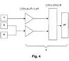
図4においては、このシステム及び上述した詳細に関するすべての部分が示されている。この図面は、捕捉デバイス1とともに軌道検出用手段2及び傾斜検出用手段3を示している。また、非常に簡略化した形で電子システム4も示されている。図面においてはこの電子システムは、基本的にシグナルコンディショナと、シグナルプロセッサと、マイクロコントローラとから構成されている。ただし、明らかなように、これは単に説明のための例であり、限定的なものではない。 In FIG. 4 all parts relating to this system and the details described above are shown. This figure shows the trajectory detection means 2 and the inclination detection means 3 together with the capture device 1. The electronic system 4 is also shown in a very simplified form. In the drawing, the electronic system basically includes a signal conditioner, a signal processor, and a microcontroller. However, as will be apparent, this is merely an illustrative example and is not limiting.
図3は、この発明によって提案されているシステムが設置されている車両を追い越そうとしているときに、車両が捕捉デバイス1によってカバーされるエリアの中にまっすぐな軌道でどのように入ってくるか、従って、システムによってどのように検出されるかを示している。 FIG. 3 shows how the vehicle enters in a straight track into the area covered by the capture device 1 when trying to overtake the vehicle in which the system proposed by the invention is installed. And thus how it is detected by the system.
明らかなように、軌道は通常は道路のカーブや不規則性などを含んでいて変動があるため、図3に示されている状況は実際の運転状況の100%のケースで起きるものではない。 Obviously, the track shown in FIG. 3 does not occur in 100% of the actual driving situation because the trajectory usually includes road curves and irregularities and fluctuates.
この発明は、車両の軌道に関する情報をどのようにして得るかに応じて、車両の軌道を見つけるための様々な実施の形態を提供している。第1の実施の形態においては、軌道検出用手段2は少なくとも一つの加速度計又は求心加速度センサを有しており、これを用いてその求心加速度を測定し、センサは求心加速度に比例する電気信号を電子システム4へ提供する。これによって、例えば、ボードコンピュータなどの車両の中央制御システムの一部であって車両の直線速度(lineal speed)を表す情報へアクセスする電子システム4は、任意の瞬間において両方のパラメータによって、車両の角速度及び曲率半径を得ることができる。というのは、ターンするときには、曲率半径に反比例し、直線速度の平方に比例する求心加速度が発生するからである。 The present invention provides various embodiments for finding a vehicle trajectory, depending on how information about the vehicle trajectory is obtained. In the first embodiment, the
別の実施の形態において提案されているように、前記回転半径は別の方法で得ることもできる。そこでは、前の実施の形態において述べた加速度計は、ターン検出を行うための脈動システム(pulsating system)から取得されたデータによって置き換えられる。脈動システムは、車両の両方の後輪にそれぞれ一つずつ配置された二つのセンサから構成されている。前記センサは各車輪の回転に比例するインパルスの形の電気信号を電子システム4へ提供する。これらの電気信号は、一方の車輪が他方の車輪よりも多く回転する場合、すなわち、車両がターンしている場合には異なる。一方の車輪と他方との間のインパルス数の違いが電子システム4によって考慮され、加速度計がセンサとして使用されている場合にそれが起きるように、車両が実際にターンしているときを知ることとは別に、車両がとる様々な軌道に対応した曲率半径を表す一連の値が様々なタイプのカーブの関数として得られる。 As suggested in other embodiments, the radius of rotation can be obtained in other ways. There, the accelerometer described in the previous embodiment is replaced by data obtained from a pulsating system for performing turn detection. The pulsation system is composed of two sensors, one on each of the rear wheels of the vehicle. The sensor provides an electrical signal in the form of an impulse proportional to the rotation of each wheel to the electronic system 4. These electrical signals are different when one wheel rotates more than the other, that is, when the vehicle is turning. Know when the vehicle is actually turning so that the difference in the number of impulses between one wheel and the other is taken into account by the electronic system 4 and that happens when the accelerometer is used as a sensor Apart from that, a series of values representing the radius of curvature corresponding to the various tracks taken by the vehicle are obtained as a function of various types of curves.
別の実施の形態においては、車両の回転半径に関する情報は車両のハンドルの中に配置されたターン検出のための少なくとも一つのデバイスによって得られる。このデバイスは軌道検出用手段2の一部である。この情報は、上述した二つの実施の形態に対してすでに説明したのと同じように処置される。 In another embodiment, the information regarding the turning radius of the vehicle is obtained by at least one device for turn detection located in the vehicle handle. This device is part of the trajectory detection means 2. This information is treated in the same way as already described for the two embodiments described above.
山道又は道路が悪かったり変形していたりしている領域で特に重要になると思われるが、車両が被る傾斜及び/又は振動を検出する傾斜検出用手段3に関して、好ましい実施の形態においては、それらは少なくとも2軸の加速度計を有している。この加速度計は車両の傾斜を測定するだけでなく、その軌道も測定するために使用される。すなわち、実際、前記2軸加速度計は軌道検出用手段2で使用されているものに置き換わっており、両方の検出用手段2及び3の一部になっている。 Although it appears to be particularly important in areas where mountain roads or roads are bad or deformed, in the preferred embodiment they relate to the
別の実施の形態に対しては、2軸加速度計によって実行されるものと同じ機能が少なくとも一つのジャイロスコープを使用することによって実行可能である。
ここまでは捕捉デバイス1については、それが何によって構成されているかを特定せずに非常に一般的な形で述べてきた。そうしてきた理由は、それが、様々な実施の形態に対して、例えば、カメラ、赤外線システム、レーダシステム及び超音波システム又はそれらの組み合わせから成るグループに含まれる任意のものでよいからである。For another embodiment, the same functions performed by a two-axis accelerometer can be performed by using at least one gyroscope.
Up to this point, the capture device 1 has been described in a very general form without specifying what constitutes it. The reason for doing so is that it can be any of the various embodiments, for example, included in the group consisting of cameras, infrared systems, radar systems and ultrasound systems or combinations thereof.
捕捉デバイス1がカメラの場合、それは軌道検出用手段2の一部にすることができ、それ自身によって捕捉された画像を表す信号を電子システム4へ提供する。そして、電子システムは連続する画像の間の違いを解析して、車両が走行する走行レーンの限界ラインなどのように、カーブの場合にその位置が変わる画像の一部を参照として、例えば、カーブの回転半径を計算する。好ましい実施の形態においては、カメラはモバイル式であり、それがカバーする視野領域を拡張するようになっている。 If the capture device 1 is a camera, it can be part of the trajectory detection means 2 and provides the electronic system 4 with a signal representing an image captured by itself. Then, the electronic system analyzes the difference between successive images and refers to a part of the image whose position changes in the case of a curve, such as a limit line of a driving lane in which the vehicle travels. Calculate the turning radius of. In the preferred embodiment, the camera is mobile and extends the field of view it covers.
別の実施の形態においては、前記捕捉デバイス1はレーダシステムである。このレーダシステムは、異なる傾斜を有する少なくとも二つのアンテナか、傾斜の異なる少なくとも二つの組み合わせアンテナ又はフラクタルアンテナを有する一つのアンテナを有している。放射はシステムに含まれているアンテナのすべて又はいくつかのみによって行われる。放射を行うアンテナの数やその選択及び放射パワーは電子システム4によって選択される。 In another embodiment, the acquisition device 1 is a radar system. The radar system has at least two antennas having different inclinations, or one antenna having at least two combined antennas or fractal antennas having different inclinations. Radiation is performed by all or some of the antennas included in the system. The number of antennas that radiate, their selection and the radiation power are selected by the electronic system 4.
別の実施の形態は捕捉デバイス1として赤外線システムを用いている。この赤外線システムは少なくとも一つの送信機及び少なくとも一つの受信機を有しており、その選択及び/又は放射パワーは電子システム4によって選択される。
別の実施の形態においては、捕捉デバイス1は超音波システムであり、少なくとも一つの送信機及び少なくとも一つの受信機を含んでいる。それらの選択及び/又はそれらの放射パワーは電子システム4によって行われる。Another embodiment uses an infrared system as the capture device 1. The infrared system has at least one transmitter and at least one receiver, the selection and / or radiation power being selected by the electronic system 4.
In another embodiment, the capture device 1 is an ultrasound system and includes at least one transmitter and at least one receiver. Their selection and / or their radiant power is performed by the electronic system 4.
前述したように、上述したシステムを組み合わせて、捕捉デバイス1によってより大きな領域又は監視エリアをカバーするようにすることも可能である。そうした組み合わせの例は、車両の死角に属していて車両に比較的近接した(おおよそ15メートル)領域をカバーするために、検出距離が100から200メートルにまで及ぶレーダシステムといっしょにカメラを使用する場合である。両方のシステムは互いに補い、追い越そうとする車両の検出をより容易かつ信頼性の高いものにする。 As described above, it is also possible to combine the systems described above so that the capture device 1 covers a larger area or monitoring area. An example of such a combination uses a camera with a radar system ranging from 100 to 200 meters to cover an area that belongs to the vehicle's blind spot and is relatively close to the vehicle (approximately 15 meters). Is the case. Both systems complement each other, making it easier and more reliable to detect vehicles that are about to pass.
この発明は、また、車両の外部環境を監視するための方法も提案している。この方法は、少なくとも一つの死角をカバーしている予め決められた監視エリア内において、前記車両に衝突しそうな物体の存在を検出するようになっている。この方法は、車両が遭遇する環境に適合した確実かつ現実的な形で前記検出を行うための提案された前記システムを使用している。 The invention also proposes a method for monitoring the external environment of the vehicle. This method is adapted to detect the presence of an object that is likely to collide with the vehicle within a predetermined surveillance area covering at least one blind spot. This method uses the proposed system for performing the detection in a reliable and realistic manner that is compatible with the environment encountered by the vehicle.
この方法は、前述した捕捉デバイス1及び電子システム4を一体化したシステムを介して、前記監視エリア内への物体の侵入を検出する段階と、前記検出を表す信号を取得する段階と、前記信号の処置、処理及び解析を行う段階と、前記解析の結果としての出力信号を発生する段階とを有している。この方法は、また、捕捉デバイス1によってカバーされる監視エリアを変更するために、前述した電子システム4と、車両の軌道検出用手段2と、傾斜検出用手段3とを介して、車両の軌道及び/又は傾斜において起こり得る変動を検出する段階と、前記起こり得る変動を表す信号の処置、処理及び解析を行う段階とをさらに有している。 The method includes detecting an intrusion of an object into the monitoring area via a system in which the above-described capturing device 1 and electronic system 4 are integrated, obtaining a signal representing the detection, and the signal The steps of performing the above processing, processing and analysis, and generating an output signal as a result of the analysis. This method also uses the electronic system 4, the vehicle trajectory detection means 2 and the inclination detection means 3 described above to change the monitoring area covered by the capture device 1. And / or detecting possible variations in slope, and processing, processing and analyzing signals representative of the possible variations.
車両の軌道及び/又は傾斜において起こり得る変動を表す前記信号の前記処置、処理及び解析の後に、この方法は、車両がとる軌道及び/又は傾斜位置の各々に対して、電子システム4によって前記変動を表す値を蓄積する段階を有している。前記値は、全体として、軌道及び/又は傾斜を捕捉デバイス1によってカバーされる監視エリアに関係付けるチャートを形成する。このチャートは電子システム4によってアクセス可能であり、それによって使用され、捕捉デバイス1によってカバーされる監視エリアを変更する。 After the treatment, processing and analysis of the signal representative of possible variations in the vehicle's trajectory and / or inclination, the method is adapted by the electronic system 4 for each of the trajectories and / or inclination positions taken by the vehicle. And storing a value representing. The values as a whole form a chart relating the trajectory and / or tilt to the monitoring area covered by the capture device 1. This chart is accessible by the electronic system 4 and is used thereby to change the monitoring area covered by the capture device 1.
起こり得るすべての環境に関して、車両に対するすべてのタイプのテストを実行する事前の校正段階において行うことのできる前記チャートが形成されると、それはメモリの中に記録される。このメモリは、電子システム4によってアクセス可能であり、及び/又は電子システム4に属する。前記チャートを参照すると、実際の運転状況において、例えば、車両が予め決められた半径のカーブに沿って走行しているときなどのように、考えられる任意の環境に車両が遭遇している実際の走行状態においては、電子システム4にはそのことを認識する。それは、この発明の方法によって使用されるシステムについて詳述したときにすでに説明した車両の軌道検出用手段2及び/又は傾斜検出用手段3に属するデバイスが前記状況が発生していることを電子システム4に教えるからであり、システム自身はカーブについて話している場合の曲率半径又は車両が走行している道路が傾斜を有しているときの傾斜角度などの前記環境の変動特性の値を計算する。例えば、曲率半径などの前記値がいったんわかると、電子システム4はチャートを参照して、捕捉デバイス1によってカバーされる監視エリアの対応する値を選択する。前述した参照から得られた値に関して、電子システム4は必要な行動を実行し、チャートを介して得られた監視エリアを実際に捕捉デバイス1がカバーするようにさせる。 Once the chart has been formed that can be performed in a pre-calibration phase that performs all types of tests on the vehicle for all possible environments, it is recorded in memory. This memory is accessible by and / or belongs to the electronic system 4. Referring to the chart, in an actual driving situation, for example, when the vehicle is encountering any conceivable environment, such as when the vehicle is traveling along a predetermined radius curve. In the running state, the electronic system 4 recognizes this. The electronic system indicates that the situation has occurred in the devices belonging to the vehicle trajectory detection means 2 and / or the inclination detection means 3 already described when the system used by the method of the invention is detailed. This is because the system itself calculates the value of the environmental fluctuation characteristics such as the radius of curvature when talking about a curve or the inclination angle when the road on which the vehicle is running has an inclination. . For example, once the value such as the radius of curvature is known, the electronic system 4 refers to the chart and selects the corresponding value of the monitoring area covered by the capture device 1. With respect to the values obtained from the above-mentioned reference, the electronic system 4 performs the necessary actions and causes the capture device 1 to actually cover the monitoring area obtained via the chart.
前記行動は捕捉デバイス1として使用されるシステムに依存する。本方法は、使用される捕捉デバイス1のタイプとは関係なく有効であり、捕捉デバイス1は、カメラ、赤外線システム、レーダシステム及び超音波システム又はそれらの組み合わせを含むグループの少なくとも一つのメンバから構成される。それらの任意のものに対して、電子システム4は一連の様々な行動を実行すると考えられる。前述したシステムを複数組み合わせた場合には、それらも組み合わせることが可能である。 Said behavior depends on the system used as the capture device 1. The method is effective regardless of the type of capture device 1 used, the capture device 1 comprising at least one member of a group comprising a camera, an infrared system, a radar system and an ultrasound system or combinations thereof. Is done. For any of them, the electronic system 4 is considered to perform a series of different actions. When a plurality of the aforementioned systems are combined, they can also be combined.
好ましい実施の形態においては、本方法は、捕捉デバイス1としてカメラを使用する段階と、電子システム4を介して捕捉デバイス1の監視エリアを変更する段階と、全体として前記エリア又はウィンドウの範囲を決める一連の点の水平及び垂直座標を変更する段階とを有している。図1及び図2においては、二つの異なる運転状況、特に、異なる曲率半径を有する二つのカーブに関して、前記ウィンドウの二つのサンプルが示されている。 In a preferred embodiment, the method determines the range of the area or window as a whole, using a camera as the capture device 1, changing the monitoring area of the capture device 1 via the electronic system 4. Changing the horizontal and vertical coordinates of the series of points. In FIGS. 1 and 2, two samples of the window are shown for two different driving situations, in particular for two curves with different radii of curvature.
前記カメラはモバイル式でも可能であり、その場合には、電子システム4を介する捕捉デバイス1の監視エリアの変更は、全体として前記エリアの範囲を決める一連の点の前記水平及び垂直座標を変更するか、又は前記モバイル式カメラを移動するか、又は両方を同時に行うことによって実行される。この方法はより大きな変更が可能である。 The camera can also be mobile, in which case changing the monitoring area of the capture device 1 via the electronic system 4 changes the horizontal and vertical coordinates of a series of points that define the area as a whole. Or by moving the mobile camera or both simultaneously. This method can be changed more greatly.
この方法は、また、この発明のシステムを説明したときにすでに述べたように、カメラによって取得された情報の少なくとも一部を使用して、電子システム4による前記情報の解析を介して車両の軌道に沿った変化を検出する可能性も考慮に入れている。 This method also uses the at least part of the information acquired by the camera, as already mentioned when describing the system of the invention, to track the vehicle via analysis of said information by the electronic system 4. The possibility of detecting changes along the line is also taken into account.
別の実施に形態においては、この方法は、異なる傾斜を有する少なくとも二つのアンテナを有するか、又は傾斜の異なる少なくとも二つのアンテナ又はフラクタルアンテナを有する一つのアンテナを有するレーダシステムを捕捉デバイス1として使用する段階と、電子システム4を介して捕捉デバイス1の監視エリアを変更する段階と、放射が行われるアンテナを選択し、及び/又はその放射パワーを変更する段階とを有している。 In another embodiment, the method uses as a capture device 1 a radar system having at least two antennas with different slopes or having one antenna with at least two antennas or fractal antennas with different slopes. And changing the monitoring area of the capture device 1 via the electronic system 4 and selecting the antenna on which radiation is performed and / or changing its radiated power.
この方法の別の形態は、捕捉デバイス1として少なくとも一つの送信機及び受信機を備えた赤外線システム又は超音波システムを使用する段階と、電子システム4を介して捕捉デバイス1の監視エリアを変更する段階と、放射する送信機を選択し、及び/又はその放射パワーを変更する段階とを有している。 Another form of the method uses an infrared or ultrasound system with at least one transmitter and receiver as the capture device 1 and changes the monitoring area of the capture device 1 via the electronic system 4. Selecting a radiating transmitter and / or changing its radiant power.
当業者は、添付されている特許請求の範囲で定義されているこの発明の範囲から逸脱することなく、上述した実施の形態に変更や修正を加えることができよう。 Those skilled in the art will be able to make changes and modifications to the above-described embodiments without departing from the scope of the invention as defined in the appended claims.
Claims (28)
Translated fromJapanese前記システムは、少なくとも一つの死角をカバーしている予め決められた監視エリア内において、前記車両と衝突しそうな物体の存在を検出するようになっており、
また、前記システムは、前記監視エリアの中に含まれる物体を表している外部から捕捉される存在に関する画像又は情報サンプルを取得するのに適した捕捉デバイス(1)と、前記捕捉デバイス(1)を介して得られた第1の入力信号を処理及び解析するための少なくとも一つのシステムを有するとともに前記解析の結果の関数として出力信号を発生する一つの電子システム(4)とを有するタイプのものであり、
前記電子システム(4)と協働する軌道検出用手段(2)を少なくともさらに有し、この軌道検出用手段(2)によって得られるとともに処理及び解析が行われた第2の信号の関数として、捕捉デバイス(1)によってカバーされる前記監視エリアを変更するようになっているシステム。A system for monitoring the external environment of an automobile, particularly a system that can be installed in an external rear view mirror,
The system is adapted to detect the presence of an object likely to collide with the vehicle within a predetermined surveillance area covering at least one blind spot,
The system also includes a capture device (1) suitable for obtaining an image or information sample relating to an externally captured presence representing an object contained in the monitoring area, and the capture device (1) Having at least one system for processing and analyzing a first input signal obtained via the and an electronic system (4) for generating an output signal as a function of the result of the analysis And
As a function of a second signal obtained by the trajectory detection means (2) and processed and analyzed, which further comprises at least trajectory detection means (2) cooperating with the electronic system (4). A system adapted to change the monitoring area covered by a capture device (1).
少なくとも一つの死角をカバーしている予め決められた監視エリア内において前記車両と衝突しそうな物体の存在を検出するようになっており、前記監視エリアの中に含まれる物体を表している外部から捕捉される存在に関する画像又は情報サンプルを取得するのに適した捕捉デバイス(1)と、電子システム(4)とを有するシステムを介して行われ、前記監視エリア内への物体の侵入を検出する段階と、この検出を表す第1の信号を取得する段階と、この第1の信号を処置、処理及び解析する段階と、前記解析の結果として出力信号を発生する段階とを有し、
前記電子システム(4)によって、また、少なくとも軌道検出用手段(2)によって、車両の軌道において起こり得る変動を検出する段階と、前記軌道において起こり得る前記変動を表す第2の信号を処置、処理及び解析して、捕捉デバイス(1)によってカバーされる監視エリアを変更する段階とをさらに有する方法。A method for monitoring the external environment of a car,
The presence of an object likely to collide with the vehicle is detected in a predetermined monitoring area that covers at least one blind spot, and from the outside representing the object included in the monitoring area This is done via a system comprising a capture device (1) suitable for obtaining images or information samples relating to the captured presence and an electronic system (4) to detect the intrusion of objects into the surveillance area Obtaining a first signal representative of the detection; treating, processing and analyzing the first signal; and generating an output signal as a result of the analysis;
Detecting a possible variation in the vehicle's trajectory by the electronic system (4) and at least by a trajectory detection means (2), and treating and processing a second signal representative of the possible variation in the trajectory And analyzing to change the monitoring area covered by the capture device (1).
Using an ultrasound system having at least one transmitter and at least one receiver as the capture device (1), and changing and radiating the monitoring area of the capture device (1) by the electronic system (4) 23. The method of claim 22, comprising selecting a transmitter and / or changing its radiant power.
Applications Claiming Priority (1)
| Application Number | Priority Date | Filing Date | Title |
|---|---|---|---|
| PCT/ES2003/000429WO2005017554A1 (en) | 2003-08-18 | 2003-08-18 | System and method for monitoring the external environment of a motor vehicle |
Publications (1)
| Publication Number | Publication Date |
|---|---|
| JP2006514382Atrue JP2006514382A (en) | 2006-04-27 |
Family
ID=34178756
Family Applications (1)
| Application Number | Title | Priority Date | Filing Date |
|---|---|---|---|
| JP2005507726APendingJP2006514382A (en) | 2003-08-18 | 2003-08-18 | System and method for monitoring the external environment of a vehicle |
Country Status (5)
| Country | Link |
|---|---|
| US (1) | US7392118B2 (en) |
| EP (1) | EP1657568B1 (en) |
| JP (1) | JP2006514382A (en) |
| AU (1) | AU2003260520A1 (en) |
| WO (1) | WO2005017554A1 (en) |
Cited By (5)
| Publication number | Priority date | Publication date | Assignee | Title |
|---|---|---|---|---|
| WO2012147187A1 (en)* | 2011-04-27 | 2012-11-01 | トヨタ自動車株式会社 | Periphery vehicle detection device |
| JP2013242679A (en)* | 2012-05-21 | 2013-12-05 | Panasonic Corp | Obstacle detection device |
| JP2019217924A (en)* | 2018-06-20 | 2019-12-26 | 本田技研工業株式会社 | Vehicle and control method |
| WO2020090320A1 (en)* | 2018-10-31 | 2020-05-07 | ソニーセミコンダクタソリューションズ株式会社 | Information processing device, information processing method, and information processing program |
| JP2021131396A (en)* | 2015-10-06 | 2021-09-09 | グーグル エルエルシーGoogle LLC | Radar-enabled sensor fusion |
Families Citing this family (11)
| Publication number | Priority date | Publication date | Assignee | Title |
|---|---|---|---|---|
| US7451046B2 (en)* | 2004-04-29 | 2008-11-11 | Sanjeev Nath | Imminent collision warning system and method |
| US7639841B2 (en)* | 2004-12-20 | 2009-12-29 | Siemens Corporation | System and method for on-road detection of a vehicle using knowledge fusion |
| ES2258399B1 (en) | 2005-02-04 | 2007-11-16 | Fico Mirrors, S.A. | METHOD AND SYSTEM TO IMPROVE THE SUPERVISION OF AN OUTSIDE ENVIRONMENT OF A MOTOR VEHICLE. |
| FR2908902B1 (en)* | 2006-11-22 | 2009-02-27 | Renault Sas | METHOD FOR LOCATING A VEHICLE WITH RESPECT TO CIRCULATION PATHWAYS AND ADAPTED VEHICLE |
| US9228836B2 (en)* | 2013-03-15 | 2016-01-05 | Cambridge Mobile Telematics | Inference of vehicular trajectory characteristics with personal mobile devices |
| DE102013009252A1 (en)* | 2013-06-03 | 2014-12-04 | Trw Automotive Gmbh | Control unit and method for an emergency steering assist function |
| JP6822303B2 (en)* | 2017-04-28 | 2021-01-27 | トヨタ自動車株式会社 | Image display device |
| KR102371616B1 (en)* | 2017-11-07 | 2022-03-07 | 현대자동차주식회사 | Apparatus and method for associating sensor data of vehicle |
| US11378956B2 (en)* | 2018-04-03 | 2022-07-05 | Baidu Usa Llc | Perception and planning collaboration framework for autonomous driving |
| CN111212456B (en)* | 2020-01-16 | 2022-07-08 | 中国电建集团成都勘测设计研究院有限公司 | Multi-path routing method for low-power-consumption long-distance Internet of things based on geographic position |
| US11798295B2 (en)* | 2021-04-27 | 2023-10-24 | GM Global Technology Operations LLC | Model free lane tracking system |
Citations (26)
| Publication number | Priority date | Publication date | Assignee | Title |
|---|---|---|---|---|
| JPH05134036A (en)* | 1991-11-14 | 1993-05-28 | Toyota Motor Corp | Vehicle-mounted radar apparatus |
| JPH064800A (en)* | 1992-06-18 | 1994-01-14 | Mitsubishi Electric Corp | Safety traveling controller for vehicle |
| JPH0632175A (en)* | 1992-07-18 | 1994-02-08 | Nissan Motor Co Ltd | Rearward image pick-up device for vehicle |
| JPH06131596A (en)* | 1992-10-21 | 1994-05-13 | Mazda Motor Corp | Obstacle detector for automobile |
| JPH06206506A (en)* | 1993-01-08 | 1994-07-26 | Mazda Motor Corp | Travel safety device of vehicle |
| JPH06293236A (en)* | 1992-12-22 | 1994-10-21 | Mitsubishi Electric Corp | Travel environment monitoring device |
| JPH06321011A (en)* | 1993-05-17 | 1994-11-22 | Mitsubishi Electric Corp | Peripheral visual field display |
| JPH06331335A (en)* | 1993-05-25 | 1994-12-02 | Matsushita Electric Ind Co Ltd | Vehicle recognition device |
| JPH076291A (en)* | 1993-03-08 | 1995-01-10 | Mazda Motor Corp | Obstacle sensor for automobile |
| JPH07311896A (en)* | 1994-05-17 | 1995-11-28 | Mazda Motor Corp | Running way estimating device for automobile |
| JPH0858503A (en)* | 1994-08-18 | 1996-03-05 | Mitsubishi Electric Corp | Rear-side danger alarm device and rear-side risk determination method |
| JPH08132997A (en)* | 1994-09-14 | 1996-05-28 | Mazda Motor Corp | Traveling path estimating device for vehicle and method for estimating it |
| JPH08156722A (en)* | 1994-12-06 | 1996-06-18 | Nissan Motor Co Ltd | Vehicle obstacle detection device and approach warning / avoidance device |
| JPH08172620A (en)* | 1994-12-16 | 1996-07-02 | Nissan Motor Co Ltd | Vehicle image input means |
| JPH0990023A (en)* | 1995-09-20 | 1997-04-04 | Toyota Motor Corp | Frequency analysis radar device |
| JPH09179989A (en)* | 1995-12-26 | 1997-07-11 | Nissan Motor Co Ltd | Road recognition device for vehicles |
| JPH11180330A (en)* | 1997-12-22 | 1999-07-06 | Mitsubishi Electric Corp | Steering angle calculation device |
| JPH11296660A (en)* | 1998-04-15 | 1999-10-29 | Nissan Motor Co Ltd | Road white line detector |
| JP2000137068A (en)* | 1998-10-30 | 2000-05-16 | Furukawa Electric Co Ltd:The | Antenna device |
| JP2000146547A (en)* | 1998-11-17 | 2000-05-26 | Toyota Central Res & Dev Lab Inc | Vehicle obstacle shape detection device |
| JP2000214256A (en)* | 1999-01-28 | 2000-08-04 | Mazda Motor Corp | Display device of vehicle |
| JP2002114117A (en)* | 2000-10-06 | 2002-04-16 | Nissan Motor Co Ltd | Inter-vehicle distance estimating device |
| JP2002114097A (en)* | 2000-10-10 | 2002-04-16 | Showa Electric Wire & Cable Co Ltd | On-board infrared imaging device |
| JP2002246786A (en)* | 2001-02-19 | 2002-08-30 | Dainippon Printing Co Ltd | Radio wave absorber |
| JP2003066139A (en)* | 2001-08-27 | 2003-03-05 | Hitachi Ltd | Radar equipment |
| JP2003510871A (en)* | 1999-09-20 | 2003-03-18 | フラクトゥス・ソシエダッド・アノニマ | Multi-level antenna |
Family Cites Families (6)
| Publication number | Priority date | Publication date | Assignee | Title |
|---|---|---|---|---|
| JP2601003B2 (en)* | 1990-09-25 | 1997-04-16 | 日産自動車株式会社 | Vehicle running condition recognition device |
| IT1256956B (en) | 1992-10-05 | 1995-12-27 | Gilardini Spa | DEVICE TO DETECT RELATIVE POSITIONS BETWEEN VEHICLES, MAINLY IN ANTI-COLLISION FUNCTION. |
| DE4407757A1 (en)* | 1993-03-08 | 1994-09-15 | Mazda Motor | Device for detecting obstacles for a vehicle |
| US5745870A (en)* | 1994-09-14 | 1998-04-28 | Mazda Motor Corporation | Traveling-path prediction apparatus and method for vehicles |
| JPH11345394A (en)* | 1998-06-03 | 1999-12-14 | Mitsubishi Electric Corp | Vehicle periphery monitoring device |
| ES2158827B1 (en) | 2000-02-18 | 2002-03-16 | Fico Mirrors Sa | DEVICE FOR DETECTION OF PRESENCE OF OBJECTS. |
- 2003
- 2003-08-18WOPCT/ES2003/000429patent/WO2005017554A1/enactiveApplication Filing
- 2003-08-18AUAU2003260520Apatent/AU2003260520A1/ennot_activeAbandoned
- 2003-08-18USUS10/534,444patent/US7392118B2/ennot_activeExpired - Lifetime
- 2003-08-18JPJP2005507726Apatent/JP2006514382A/enactivePending
- 2003-08-18EPEP03818087.3Apatent/EP1657568B1/ennot_activeExpired - Lifetime
Patent Citations (26)
| Publication number | Priority date | Publication date | Assignee | Title |
|---|---|---|---|---|
| JPH05134036A (en)* | 1991-11-14 | 1993-05-28 | Toyota Motor Corp | Vehicle-mounted radar apparatus |
| JPH064800A (en)* | 1992-06-18 | 1994-01-14 | Mitsubishi Electric Corp | Safety traveling controller for vehicle |
| JPH0632175A (en)* | 1992-07-18 | 1994-02-08 | Nissan Motor Co Ltd | Rearward image pick-up device for vehicle |
| JPH06131596A (en)* | 1992-10-21 | 1994-05-13 | Mazda Motor Corp | Obstacle detector for automobile |
| JPH06293236A (en)* | 1992-12-22 | 1994-10-21 | Mitsubishi Electric Corp | Travel environment monitoring device |
| JPH06206506A (en)* | 1993-01-08 | 1994-07-26 | Mazda Motor Corp | Travel safety device of vehicle |
| JPH076291A (en)* | 1993-03-08 | 1995-01-10 | Mazda Motor Corp | Obstacle sensor for automobile |
| JPH06321011A (en)* | 1993-05-17 | 1994-11-22 | Mitsubishi Electric Corp | Peripheral visual field display |
| JPH06331335A (en)* | 1993-05-25 | 1994-12-02 | Matsushita Electric Ind Co Ltd | Vehicle recognition device |
| JPH07311896A (en)* | 1994-05-17 | 1995-11-28 | Mazda Motor Corp | Running way estimating device for automobile |
| JPH0858503A (en)* | 1994-08-18 | 1996-03-05 | Mitsubishi Electric Corp | Rear-side danger alarm device and rear-side risk determination method |
| JPH08132997A (en)* | 1994-09-14 | 1996-05-28 | Mazda Motor Corp | Traveling path estimating device for vehicle and method for estimating it |
| JPH08156722A (en)* | 1994-12-06 | 1996-06-18 | Nissan Motor Co Ltd | Vehicle obstacle detection device and approach warning / avoidance device |
| JPH08172620A (en)* | 1994-12-16 | 1996-07-02 | Nissan Motor Co Ltd | Vehicle image input means |
| JPH0990023A (en)* | 1995-09-20 | 1997-04-04 | Toyota Motor Corp | Frequency analysis radar device |
| JPH09179989A (en)* | 1995-12-26 | 1997-07-11 | Nissan Motor Co Ltd | Road recognition device for vehicles |
| JPH11180330A (en)* | 1997-12-22 | 1999-07-06 | Mitsubishi Electric Corp | Steering angle calculation device |
| JPH11296660A (en)* | 1998-04-15 | 1999-10-29 | Nissan Motor Co Ltd | Road white line detector |
| JP2000137068A (en)* | 1998-10-30 | 2000-05-16 | Furukawa Electric Co Ltd:The | Antenna device |
| JP2000146547A (en)* | 1998-11-17 | 2000-05-26 | Toyota Central Res & Dev Lab Inc | Vehicle obstacle shape detection device |
| JP2000214256A (en)* | 1999-01-28 | 2000-08-04 | Mazda Motor Corp | Display device of vehicle |
| JP2003510871A (en)* | 1999-09-20 | 2003-03-18 | フラクトゥス・ソシエダッド・アノニマ | Multi-level antenna |
| JP2002114117A (en)* | 2000-10-06 | 2002-04-16 | Nissan Motor Co Ltd | Inter-vehicle distance estimating device |
| JP2002114097A (en)* | 2000-10-10 | 2002-04-16 | Showa Electric Wire & Cable Co Ltd | On-board infrared imaging device |
| JP2002246786A (en)* | 2001-02-19 | 2002-08-30 | Dainippon Printing Co Ltd | Radio wave absorber |
| JP2003066139A (en)* | 2001-08-27 | 2003-03-05 | Hitachi Ltd | Radar equipment |
Cited By (14)
| Publication number | Priority date | Publication date | Assignee | Title |
|---|---|---|---|---|
| WO2012147187A1 (en)* | 2011-04-27 | 2012-11-01 | トヨタ自動車株式会社 | Periphery vehicle detection device |
| JPWO2012147187A1 (en)* | 2011-04-27 | 2014-07-28 | トヨタ自動車株式会社 | Surrounding vehicle detection device |
| JP2013242679A (en)* | 2012-05-21 | 2013-12-05 | Panasonic Corp | Obstacle detection device |
| US11693092B2 (en) | 2015-10-06 | 2023-07-04 | Google Llc | Gesture recognition using multiple antenna |
| JP2021131396A (en)* | 2015-10-06 | 2021-09-09 | グーグル エルエルシーGoogle LLC | Radar-enabled sensor fusion |
| US11592909B2 (en) | 2015-10-06 | 2023-02-28 | Google Llc | Fine-motion virtual-reality or augmented-reality control using radar |
| JP7257447B2 (en) | 2015-10-06 | 2023-04-13 | グーグル エルエルシー | Sensor fusion for radar |
| US11656336B2 (en) | 2015-10-06 | 2023-05-23 | Google Llc | Advanced gaming and virtual reality control using radar |
| US11698439B2 (en) | 2015-10-06 | 2023-07-11 | Google Llc | Gesture recognition using multiple antenna |
| US11698438B2 (en) | 2015-10-06 | 2023-07-11 | Google Llc | Gesture recognition using multiple antenna |
| US12085670B2 (en) | 2015-10-06 | 2024-09-10 | Google Llc | Advanced gaming and virtual reality control using radar |
| US12117560B2 (en) | 2015-10-06 | 2024-10-15 | Google Llc | Radar-enabled sensor fusion |
| JP2019217924A (en)* | 2018-06-20 | 2019-12-26 | 本田技研工業株式会社 | Vehicle and control method |
| WO2020090320A1 (en)* | 2018-10-31 | 2020-05-07 | ソニーセミコンダクタソリューションズ株式会社 | Information processing device, information processing method, and information processing program |
Also Published As
| Publication number | Publication date |
|---|---|
| EP1657568A1 (en) | 2006-05-17 |
| EP1657568B1 (en) | 2018-10-10 |
| US20060111819A1 (en) | 2006-05-25 |
| WO2005017554A1 (en) | 2005-02-24 |
| US7392118B2 (en) | 2008-06-24 |
| AU2003260520A1 (en) | 2005-03-07 |
Similar Documents
| Publication | Publication Date | Title |
|---|---|---|
| JP2006514382A (en) | System and method for monitoring the external environment of a vehicle | |
| US9437111B2 (en) | Boundary detection system | |
| US11131766B2 (en) | Method for the recognition of an object | |
| US6903677B2 (en) | Collision prediction device, method of predicting collision, and computer product | |
| US8081794B2 (en) | Method for imaging the surrounding of a vehicle | |
| US11608055B2 (en) | Enhanced autonomous systems with sound sensor arrays | |
| CN109686031B (en) | Identification following method based on security | |
| US20110235864A1 (en) | Moving object trajectory estimating device | |
| US8140226B2 (en) | Security system and a method to derive a security signal | |
| EP1367411A2 (en) | Collision detection system and method of estimating miss distance | |
| CN109196568A (en) | Method for providing information about pedestrians in the surroundings of a vehicle and method for controlling the vehicle | |
| EP2846172A1 (en) | Warning system and method | |
| US7158051B2 (en) | Lane changing assist system for an automotive vehicle | |
| CN111742235A (en) | Method and system for identifying vacant parking spaces suitable for a vehicle | |
| JP2019500683A (en) | Method for capturing a peripheral region of a powered vehicle having object classification, control device, driver support system, and powered vehicle | |
| JP2011227551A (en) | Meander driving detection device for vehicle | |
| JP2009083743A (en) | Warning device for vehicle | |
| JP3847738B2 (en) | Vehicle perimeter monitoring system | |
| JP4792865B2 (en) | Vehicle alarm device | |
| CN112542060B (en) | Rear side alarm device for vehicle | |
| KR102504984B1 (en) | Apparatus and method for detecting and treating dangerous situation in vehicle | |
| JP6510052B2 (en) | Method for detecting the shielding of a sensor device of a motor vehicle by an object, a computer device, a driver assistance system and a motor vehicle | |
| CN114390989B (en) | Vehicle control equipment and control method thereof | |
| CN116442993A (en) | Vehicle control apparatus and vehicle control method | |
| JP2024523064A (en) | Systems and methods for vehicles |
Legal Events
| Date | Code | Title | Description |
|---|---|---|---|
| A131 | Notification of reasons for refusal | Free format text:JAPANESE INTERMEDIATE CODE: A131 Effective date:20070821 | |
| A601 | Written request for extension of time | Free format text:JAPANESE INTERMEDIATE CODE: A601 Effective date:20071120 | |
| A602 | Written permission of extension of time | Free format text:JAPANESE INTERMEDIATE CODE: A602 Effective date:20071204 | |
| A601 | Written request for extension of time | Free format text:JAPANESE INTERMEDIATE CODE: A601 Effective date:20071220 | |
| A602 | Written permission of extension of time | Free format text:JAPANESE INTERMEDIATE CODE: A602 Effective date:20080115 | |
| A521 | Request for written amendment filed | Free format text:JAPANESE INTERMEDIATE CODE: A523 Effective date:20080117 | |
| A131 | Notification of reasons for refusal | Free format text:JAPANESE INTERMEDIATE CODE: A131 Effective date:20080219 | |
| A601 | Written request for extension of time | Free format text:JAPANESE INTERMEDIATE CODE: A601 Effective date:20080519 | |
| A602 | Written permission of extension of time | Free format text:JAPANESE INTERMEDIATE CODE: A602 Effective date:20080526 | |
| A601 | Written request for extension of time | Free format text:JAPANESE INTERMEDIATE CODE: A601 Effective date:20080618 | |
| A602 | Written permission of extension of time | Free format text:JAPANESE INTERMEDIATE CODE: A602 Effective date:20080701 | |
| A601 | Written request for extension of time | Free format text:JAPANESE INTERMEDIATE CODE: A601 Effective date:20080718 | |
| A602 | Written permission of extension of time | Free format text:JAPANESE INTERMEDIATE CODE: A602 Effective date:20080805 | |
| A521 | Request for written amendment filed | Free format text:JAPANESE INTERMEDIATE CODE: A523 Effective date:20080818 | |
| A02 | Decision of refusal | Free format text:JAPANESE INTERMEDIATE CODE: A02 Effective date:20090224 |