JP2006513809A - Apparatus and method for inserting an intra-aortic catheter through a delivery sheath - Google Patents
Apparatus and method for inserting an intra-aortic catheter through a delivery sheathDownload PDFInfo
- Publication number
- JP2006513809A JP2006513809AJP2005501384AJP2005501384AJP2006513809AJP 2006513809 AJP2006513809 AJP 2006513809AJP 2005501384 AJP2005501384 AJP 2005501384AJP 2005501384 AJP2005501384 AJP 2005501384AJP 2006513809 AJP2006513809 AJP 2006513809A
- Authority
- JP
- Japan
- Prior art keywords
- lumen
- distal
- delivery
- proximal
- introducer sheath
- Prior art date
- Legal status (The legal status is an assumption and is not a legal conclusion. Google has not performed a legal analysis and makes no representation as to the accuracy of the status listed.)
- Pending
Links
- 238000000034methodMethods0.000titleclaimsdescription59
- 210000002254renal arteryAnatomy0.000claimsabstractdescription48
- 238000003780insertionMethods0.000claimsabstractdescription34
- 230000037431insertionEffects0.000claimsabstractdescription34
- 230000002146bilateral effectEffects0.000claimsabstractdescription32
- 210000000702aorta abdominalAnatomy0.000claimsabstractdescription8
- 210000005227renal systemAnatomy0.000claimsabstractdescription8
- 238000002560therapeutic procedureMethods0.000claimsabstractdescription5
- 239000012530fluidSubstances0.000claimsdescription97
- 239000003814drugSubstances0.000claimsdescription66
- 229940079593drugDrugs0.000claimsdescription55
- 210000003734kidneyAnatomy0.000claimsdescription32
- 238000001802infusionMethods0.000claimsdescription23
- 238000011282treatmentMethods0.000claimsdescription22
- 238000002347injectionMethods0.000claimsdescription20
- 239000007924injectionSubstances0.000claimsdescription20
- 230000002792vascularEffects0.000claimsdescription14
- 230000023597hemostasisEffects0.000claimsdescription12
- 230000007704transitionEffects0.000claimsdescription11
- 239000000463materialSubstances0.000claimsdescription7
- 238000001356surgical procedureMethods0.000claimsdescription3
- 230000000903blocking effectEffects0.000claimsdescription2
- 230000003187abdominal effectEffects0.000claims4
- 238000002955isolationMethods0.000claims2
- 210000001124body fluidAnatomy0.000claims1
- 239000010839body fluidSubstances0.000claims1
- 238000002583angiographyMethods0.000abstractdescription5
- 230000008878couplingEffects0.000abstract1
- 238000010168coupling processMethods0.000abstract1
- 238000005859coupling reactionMethods0.000abstract1
- 238000007920subcutaneous administrationMethods0.000abstract1
- 108091006146ChannelsProteins0.000description32
- 229940124549vasodilatorDrugs0.000description18
- 239000003071vasodilator agentSubstances0.000description18
- 230000008901benefitEffects0.000description16
- FAPWRFPIFSIZLT-UHFFFAOYSA-MSodium chlorideChemical compound[Na+].[Cl-]FAPWRFPIFSIZLT-UHFFFAOYSA-M0.000description14
- 210000000709aortaAnatomy0.000description13
- 210000001367arteryAnatomy0.000description13
- 208000033626Renal failure acuteDiseases0.000description12
- 201000011040acute kidney failureDiseases0.000description12
- 239000003550markerSubstances0.000description11
- XQYZDYMELSJDRZ-UHFFFAOYSA-NpapavarineNatural productsC1=C(OC)C(OC)=CC=C1CC1=NC=CC2=CC(OC)=C(OC)C=C12XQYZDYMELSJDRZ-UHFFFAOYSA-N0.000description11
- 230000009885systemic effectEffects0.000description11
- 206010007559Cardiac failure congestiveDiseases0.000description10
- 239000003795chemical substances by applicationSubstances0.000description10
- 229920000642polymerPolymers0.000description10
- 201000003068rheumatic feverDiseases0.000description10
- 210000004369bloodAnatomy0.000description9
- 239000008280bloodSubstances0.000description9
- 230000017531blood circulationEffects0.000description9
- 238000012377drug deliveryMethods0.000description9
- 230000003287optical effectEffects0.000description9
- 230000002439hemostatic effectEffects0.000description8
- 230000002829reductive effectEffects0.000description8
- 239000011780sodium chlorideSubstances0.000description8
- 230000000694effectsEffects0.000description7
- 20800002681747,XYY syndromeDiseases0.000description6
- 230000009286beneficial effectEffects0.000description6
- 210000001105femoral arteryAnatomy0.000description6
- 238000012986modificationMethods0.000description6
- 230000004048modificationEffects0.000description6
- 229960001789papaverineDrugs0.000description6
- 239000000126substanceSubstances0.000description6
- 229940124597therapeutic agentDrugs0.000description6
- 229930008281A03AD01 - PapaverineNatural products0.000description5
- 230000000747cardiac effectEffects0.000description5
- 238000002594fluoroscopyMethods0.000description5
- 230000014759maintenance of locationEffects0.000description5
- 230000000699topical effectEffects0.000description5
- 229960002724fenoldopamDrugs0.000description4
- TVURRHSHRRELCG-UHFFFAOYSA-NfenoldopamChemical compoundC1=CC(O)=CC=C1C1C2=CC(O)=C(O)C(Cl)=C2CCNC1TVURRHSHRRELCG-UHFFFAOYSA-N0.000description4
- 238000011010flushing procedureMethods0.000description4
- 210000000056organAnatomy0.000description4
- 238000011144upstream manufacturingMethods0.000description4
- 230000024883vasodilationEffects0.000description4
- 206010019280Heart failuresDiseases0.000description3
- 206010047139VasoconstrictionDiseases0.000description3
- 230000015572biosynthetic processEffects0.000description3
- 230000036772blood pressureEffects0.000description3
- 230000008859changeEffects0.000description3
- 238000012790confirmationMethods0.000description3
- 210000004351coronary vesselAnatomy0.000description3
- 230000006378damageEffects0.000description3
- 238000013461designMethods0.000description3
- 239000000032diagnostic agentSubstances0.000description3
- 229940039227diagnostic agentDrugs0.000description3
- 238000009552doppler ultrasonographyMethods0.000description3
- 239000000975dyeSubstances0.000description3
- 238000003384imaging methodMethods0.000description3
- 208000017169kidney diseaseDiseases0.000description3
- 230000003907kidney functionEffects0.000description3
- 239000007788liquidSubstances0.000description3
- 230000002441reversible effectEffects0.000description3
- 238000011477surgical interventionMethods0.000description3
- 238000003786synthesis reactionMethods0.000description3
- 230000025033vasoconstrictionEffects0.000description3
- 230000000007visual effectEffects0.000description3
- 208000009304Acute Kidney InjuryDiseases0.000description2
- CVKUMNRCIJMVAR-UHFFFAOYSA-NFenoldopam mesylateChemical compoundCS(O)(=O)=O.C1=CC(O)=CC=C1C1C2=CC(O)=C(O)C(Cl)=C2CCNC1CVKUMNRCIJMVAR-UHFFFAOYSA-N0.000description2
- 241000408529LibraSpecies0.000description2
- 208000012998acute renal failureDiseases0.000description2
- OIRDTQYFTABQOQ-KQYNXXCUSA-NadenosineChemical compoundC1=NC=2C(N)=NC=NC=2N1[C@@H]1O[C@H](CO)[C@@H](O)[C@H]1OOIRDTQYFTABQOQ-KQYNXXCUSA-N0.000description2
- 210000003484anatomyAnatomy0.000description2
- 238000002399angioplastyMethods0.000description2
- 238000000429assemblyMethods0.000description2
- 230000000712assemblyEffects0.000description2
- 210000004204blood vesselAnatomy0.000description2
- 239000000994contrast dyeSubstances0.000description2
- CVSVTCORWBXHQV-UHFFFAOYSA-NcreatineChemical compoundNC(=[NH2+])N(C)CC([O-])=OCVSVTCORWBXHQV-UHFFFAOYSA-N0.000description2
- DDRJAANPRJIHGJ-UHFFFAOYSA-NcreatinineChemical compoundCN1CC(=O)NC1=NDDRJAANPRJIHGJ-UHFFFAOYSA-N0.000description2
- 230000003247decreasing effectEffects0.000description2
- 238000003745diagnosisMethods0.000description2
- 201000010099diseaseDiseases0.000description2
- 208000037265diseases, disorders, signs and symptomsDiseases0.000description2
- VYFYYTLLBUKUHU-UHFFFAOYSA-NdopamineChemical compoundNCCC1=CC=C(O)C(O)=C1VYFYYTLLBUKUHU-UHFFFAOYSA-N0.000description2
- 238000005516engineering processMethods0.000description2
- 229960004009fenoldopam mesylateDrugs0.000description2
- 238000001631haemodialysisMethods0.000description2
- 230000000322hemodialysisEffects0.000description2
- 230000006872improvementEffects0.000description2
- 230000000670limiting effectEffects0.000description2
- 239000000203mixtureSubstances0.000description2
- 229910001000nickel titaniumInorganic materials0.000description2
- 230000002093peripheral effectEffects0.000description2
- 230000002265preventionEffects0.000description2
- 230000000069prophylactic effectEffects0.000description2
- 230000002787reinforcementEffects0.000description2
- 210000002966serumAnatomy0.000description2
- ZFXYFBGIUFBOJW-UHFFFAOYSA-NtheophyllineChemical compoundO=C1N(C)C(=O)N(C)C2=C1NC=N2ZFXYFBGIUFBOJW-UHFFFAOYSA-N0.000description2
- 238000004448titrationMethods0.000description2
- 238000002604ultrasonographyMethods0.000description2
- ZCYVEMRRCGMTRW-UHFFFAOYSA-N7553-56-2Chemical compound[I]ZCYVEMRRCGMTRW-UHFFFAOYSA-N0.000description1
- 206010002091AnaesthesiaDiseases0.000description1
- 239000002126C01EB10 - AdenosineSubstances0.000description1
- 229940127291Calcium channel antagonistDrugs0.000description1
- 208000006017Cardiac TamponadeDiseases0.000description1
- FBPFZTCFMRRESA-KVTDHHQDSA-ND-MannitolChemical compoundOC[C@@H](O)[C@@H](O)[C@H](O)[C@H](O)COFBPFZTCFMRRESA-KVTDHHQDSA-N0.000description1
- 208000003870Drug OverdoseDiseases0.000description1
- HTTJABKRGRZYRN-UHFFFAOYSA-NHeparinChemical compoundOC1C(NC(=O)C)C(O)OC(COS(O)(=O)=O)C1OC1C(OS(O)(=O)=O)C(O)C(OC2C(C(OS(O)(=O)=O)C(OC3C(C(O)C(O)C(O3)C(O)=O)OS(O)(=O)=O)C(CO)O2)NS(O)(=O)=O)C(C(O)=O)O1HTTJABKRGRZYRN-UHFFFAOYSA-N0.000description1
- 206010020751HypersensitivityDiseases0.000description1
- 206010020772HypertensionDiseases0.000description1
- PWKSKIMOESPYIA-BYPYZUCNSA-NL-N-acetyl-CysteineChemical compoundCC(=O)N[C@@H](CS)C(O)=OPWKSKIMOESPYIA-BYPYZUCNSA-N0.000description1
- 229930195725MannitolNatural products0.000description1
- 241001465754MetazoaSpecies0.000description1
- AFVFQIVMOAPDHO-UHFFFAOYSA-NMethanesulfonic acidChemical compoundCS(O)(=O)=OAFVFQIVMOAPDHO-UHFFFAOYSA-N0.000description1
- SNIOPGDIGTZGOP-UHFFFAOYSA-NNitroglycerinChemical compound[O-][N+](=O)OCC(O[N+]([O-])=O)CO[N+]([O-])=OSNIOPGDIGTZGOP-UHFFFAOYSA-N0.000description1
- 239000000006NitroglycerinSubstances0.000description1
- 206010030113OedemaDiseases0.000description1
- 206010033296OverdosesDiseases0.000description1
- 206010037423Pulmonary oedemaDiseases0.000description1
- 206010062237Renal impairmentDiseases0.000description1
- 206010040047SepsisDiseases0.000description1
- 206010040070Septic ShockDiseases0.000description1
- 206010040738Sinus arrestDiseases0.000description1
- 102000003990Urokinase-type plasminogen activatorHuman genes0.000description1
- 108090000435Urokinase-type plasminogen activatorProteins0.000description1
- 208000024248Vascular System injuryDiseases0.000description1
- 208000012339Vascular injuryDiseases0.000description1
- 208000027418Wounds and injuryDiseases0.000description1
- 238000010521absorption reactionMethods0.000description1
- OIPILFWXSMYKGL-UHFFFAOYSA-NacetylcholineChemical compoundCC(=O)OCC[N+](C)(C)COIPILFWXSMYKGL-UHFFFAOYSA-N0.000description1
- 229960004373acetylcholineDrugs0.000description1
- 229960004308acetylcysteineDrugs0.000description1
- 229960005305adenosineDrugs0.000description1
- 239000000695adrenergic alpha-agonistSubstances0.000description1
- 208000026935allergic diseaseDiseases0.000description1
- 230000037005anaesthesiaEffects0.000description1
- 239000002220antihypertensive agentSubstances0.000description1
- 229940127088antihypertensive drugDrugs0.000description1
- 239000003963antioxidant agentSubstances0.000description1
- 230000000740bleeding effectEffects0.000description1
- 210000000746body regionAnatomy0.000description1
- 230000037396body weightEffects0.000description1
- 239000000480calcium channel blockerSubstances0.000description1
- 210000005242cardiac chamberAnatomy0.000description1
- 210000001715carotid arteryAnatomy0.000description1
- 238000006243chemical reactionMethods0.000description1
- 238000004891communicationMethods0.000description1
- 239000002131composite materialSubstances0.000description1
- 150000001875compoundsChemical class0.000description1
- 230000006835compressionEffects0.000description1
- 238000007906compressionMethods0.000description1
- 239000002872contrast mediaSubstances0.000description1
- 238000007796conventional methodMethods0.000description1
- 238000002586coronary angiographyMethods0.000description1
- 229940072645coumadinDrugs0.000description1
- 229960003624creatineDrugs0.000description1
- 239000006046creatineSubstances0.000description1
- 229940109239creatinineDrugs0.000description1
- 238000011161developmentMethods0.000description1
- 206010012601diabetes mellitusDiseases0.000description1
- 238000002405diagnostic procedureMethods0.000description1
- 238000010586diagramMethods0.000description1
- 230000010339dilationEffects0.000description1
- 239000002934diureticSubstances0.000description1
- 229940030606diureticsDrugs0.000description1
- 229960003638dopamineDrugs0.000description1
- 231100000725drug overdoseToxicity0.000description1
- 230000002526effect on cardiovascular systemEffects0.000description1
- 238000004299exfoliationMethods0.000description1
- 238000001125extrusionMethods0.000description1
- 239000003527fibrinolytic agentSubstances0.000description1
- 238000011049fillingMethods0.000description1
- 238000001914filtrationMethods0.000description1
- ZZUFCTLCJUWOSV-UHFFFAOYSA-NfurosemideChemical compoundC1=C(Cl)C(S(=O)(=O)N)=CC(C(O)=O)=C1NCC1=CC=CO1ZZUFCTLCJUWOSV-UHFFFAOYSA-N0.000description1
- 229960003883furosemideDrugs0.000description1
- 239000007789gasSubstances0.000description1
- 230000002496gastric effectEffects0.000description1
- 239000000499gelSubstances0.000description1
- 229960003711glyceryl trinitrateDrugs0.000description1
- 210000004013groinAnatomy0.000description1
- 230000000004hemodynamic effectEffects0.000description1
- 229960002897heparinDrugs0.000description1
- 229920000669heparinPolymers0.000description1
- 230000009610hypersensitivityEffects0.000description1
- 210000003090iliac arteryAnatomy0.000description1
- 239000007943implantSubstances0.000description1
- 238000001727in vivoMethods0.000description1
- 208000014674injuryDiseases0.000description1
- 238000013152interventional procedureMethods0.000description1
- 238000001990intravenous administrationMethods0.000description1
- 229910052740iodineInorganic materials0.000description1
- 239000011630iodineSubstances0.000description1
- 208000028867ischemiaDiseases0.000description1
- 230000000302ischemic effectEffects0.000description1
- 230000007774longtermEffects0.000description1
- 238000007726management methodMethods0.000description1
- 235000010355mannitolNutrition0.000description1
- 239000000594mannitolSubstances0.000description1
- 238000010297mechanical methods and processMethods0.000description1
- 230000007246mechanismEffects0.000description1
- 229910052751metalInorganic materials0.000description1
- 239000002184metalSubstances0.000description1
- 238000012544monitoring processMethods0.000description1
- 208000010125myocardial infarctionDiseases0.000description1
- 230000037125natural defenseEffects0.000description1
- 201000001119neuropathyDiseases0.000description1
- 230000007823neuropathyEffects0.000description1
- HLXZNVUGXRDIFK-UHFFFAOYSA-Nnickel titaniumChemical compound[Ti].[Ti].[Ti].[Ti].[Ti].[Ti].[Ti].[Ti].[Ti].[Ti].[Ti].[Ni].[Ni].[Ni].[Ni].[Ni].[Ni].[Ni].[Ni].[Ni].[Ni].[Ni].[Ni].[Ni].[Ni]HLXZNVUGXRDIFK-UHFFFAOYSA-N0.000description1
- HYIMSNHJOBLJNT-UHFFFAOYSA-NnifedipineChemical compoundCOC(=O)C1=C(C)NC(C)=C(C(=O)OC)C1C1=CC=CC=C1[N+]([O-])=OHYIMSNHJOBLJNT-UHFFFAOYSA-N0.000description1
- 229960001597nifedipineDrugs0.000description1
- -1nitroplussideChemical compound0.000description1
- 230000036961partial effectEffects0.000description1
- 230000010412perfusionEffects0.000description1
- 208000033808peripheral neuropathyDiseases0.000description1
- 230000035479physiological effects, processes and functionsEffects0.000description1
- 239000004810polytetrafluoroethyleneSubstances0.000description1
- 229920001343polytetrafluoroethylenePolymers0.000description1
- 231100000857poor renal functionToxicity0.000description1
- 239000000843powderSubstances0.000description1
- 108090000765processed proteins & peptidesProteins0.000description1
- 229940043274prophylactic drugDrugs0.000description1
- 238000011321prophylaxisMethods0.000description1
- 208000005333pulmonary edemaDiseases0.000description1
- 230000002685pulmonary effectEffects0.000description1
- 230000010349pulsationEffects0.000description1
- 230000005855radiationEffects0.000description1
- 230000009467reductionEffects0.000description1
- 230000008327renal blood flowEffects0.000description1
- 230000008439repair processEffects0.000description1
- 238000011160researchMethods0.000description1
- 230000004044responseEffects0.000description1
- 238000000926separation methodMethods0.000description1
- 230000036303septic shockEffects0.000description1
- 239000012781shape memory materialSubstances0.000description1
- 238000004904shorteningMethods0.000description1
- 239000007787solidSubstances0.000description1
- 239000010935stainless steelSubstances0.000description1
- 229910001220stainless steelInorganic materials0.000description1
- 238000012360testing methodMethods0.000description1
- 229960000278theophyllineDrugs0.000description1
- 238000011287therapeutic doseMethods0.000description1
- 229940126585therapeutic drugDrugs0.000description1
- 230000001225therapeutic effectEffects0.000description1
- 238000011200topical administrationMethods0.000description1
- 230000005945translocationEffects0.000description1
- 239000012780transparent materialSubstances0.000description1
- 230000000472traumatic effectEffects0.000description1
- 229960005356urokinaseDrugs0.000description1
- 230000002861ventricularEffects0.000description1
- PJVWKTKQMONHTI-UHFFFAOYSA-NwarfarinChemical compoundOC=1C2=CC=CC=C2OC(=O)C=1C(CC(=O)C)C1=CC=CC=C1PJVWKTKQMONHTI-UHFFFAOYSA-N0.000description1
- 239000002699waste materialSubstances0.000description1
Images


Classifications
- A—HUMAN NECESSITIES
- A61—MEDICAL OR VETERINARY SCIENCE; HYGIENE
- A61M—DEVICES FOR INTRODUCING MEDIA INTO, OR ONTO, THE BODY; DEVICES FOR TRANSDUCING BODY MEDIA OR FOR TAKING MEDIA FROM THE BODY; DEVICES FOR PRODUCING OR ENDING SLEEP OR STUPOR
- A61M25/00—Catheters; Hollow probes
- A61M25/0043—Catheters; Hollow probes characterised by structural features
- A—HUMAN NECESSITIES
- A61—MEDICAL OR VETERINARY SCIENCE; HYGIENE
- A61M—DEVICES FOR INTRODUCING MEDIA INTO, OR ONTO, THE BODY; DEVICES FOR TRANSDUCING BODY MEDIA OR FOR TAKING MEDIA FROM THE BODY; DEVICES FOR PRODUCING OR ENDING SLEEP OR STUPOR
- A61M25/00—Catheters; Hollow probes
- A61M25/01—Introducing, guiding, advancing, emplacing or holding catheters
- A61M25/06—Body-piercing guide needles or the like
- A61M25/0662—Guide tubes
- A—HUMAN NECESSITIES
- A61—MEDICAL OR VETERINARY SCIENCE; HYGIENE
- A61M—DEVICES FOR INTRODUCING MEDIA INTO, OR ONTO, THE BODY; DEVICES FOR TRANSDUCING BODY MEDIA OR FOR TAKING MEDIA FROM THE BODY; DEVICES FOR PRODUCING OR ENDING SLEEP OR STUPOR
- A61M39/00—Tubes, tube connectors, tube couplings, valves, access sites or the like, specially adapted for medical use
- A61M39/02—Access sites
- A61M39/06—Haemostasis valves, i.e. gaskets sealing around a needle, catheter or the like, closing on removal thereof
Landscapes
- Health & Medical Sciences (AREA)
- Life Sciences & Earth Sciences (AREA)
- Biophysics (AREA)
- Pulmonology (AREA)
- Engineering & Computer Science (AREA)
- Anesthesiology (AREA)
- Biomedical Technology (AREA)
- Heart & Thoracic Surgery (AREA)
- Hematology (AREA)
- Animal Behavior & Ethology (AREA)
- General Health & Medical Sciences (AREA)
- Public Health (AREA)
- Veterinary Medicine (AREA)
- Media Introduction/Drainage Providing Device (AREA)
- Infusion, Injection, And Reservoir Apparatuses (AREA)
Abstract
Translated fromJapaneseDescription
Translated fromJapanese (関連出願の引用)
本願は、2002年9月20日に出願された、米国仮出願番号60/412,476(この全体が、参考として本明細書中に援用される)から優先権を主張する。(Citation of related application)
This application claims priority from US Provisional Application No. 60 / 412,476, filed Sep. 20, 2002, the entirety of which is incorporated herein by reference.
本願は、2003年7月9日に出願された、米国仮出願番号60/486,206(この全体が、参考として本明細書中に援用される)から優先権を主張する。 This application claims priority from US Provisional Application No. 60 / 486,206, filed Jul. 9, 2003, which is incorporated herein by reference in its entirety.
本願は、速達郵便物番号EV35230517USによって2002年9月20日に出願された、米国仮出願番号60/412,476(この全体が、参考として本明細書中に援用される)から優先権を主張する。 This application claims priority from US Provisional Application No. 60 / 412,476, which is hereby incorporated by reference in its entirety, filed Sep. 20, 2002 by Express Mail No. EV35253017US. To do.
(連邦により補助された研究または開発に関する言及)
適用なし。(Reference to federally assisted research or development)
Not applicable.
(コンパクトディスクで提出された、参考として援用される内容)
適用なし。(Contents submitted on a compact disc and used as a reference)
Not applicable.
(発明の背景)
(1.発明の分野)
本発明は、医療デバイスの分野に関し、そしてより具体的には、流体または薬剤を、患者の身体内に局所的に送達するためのカテーテルを挿入するためのシステムおよび方法に関する。なおより具体的には、本発明は、流体または薬剤を、分枝血管または体腔内へと、それぞれ主要な脈管または管腔から、特に、患者における大動脈から延びる腎臓動脈内に局所的に送達するためのカテーテルを挿入するための、システムおよび方法に関する。(Background of the Invention)
(1. Field of the Invention)
The present invention relates to the field of medical devices and, more particularly, to systems and methods for inserting a catheter for locally delivering a fluid or drug into a patient's body. Even more specifically, the present invention delivers fluids or drugs locally into branch vessels or body cavities, respectively, from the main vessels or lumens, particularly into the renal arteries that extend from the aorta in the patient. The present invention relates to a system and method for inserting a catheter.
(2.関連技術の説明)
流体または他の薬剤を、種々の身体領域(脈管が挙げられる)または他の身体空間(例えば、器官もしくは心臓チャンバ)に局所送達するための、多くの様々な医療デバイスシステムおよび方法は、以前に開示された。局所「流体」送達システムは、薬物または他の薬剤を含み得るか、あるいはさらに、身体自体の流体を局所的に送達すること(例えば、人工的に増強された血液輸送(例えば、1つの場所から別の場所への血液の方向付けもしくは遮断のような、身体内全体で、あるいは外部血液ポンプなどを介するような、体外様式のいずれか))を含み得る。局所的な「薬剤」送達システムは、本明細書中で、一般に、薬剤のような外来組成物(これには、薬物または他の有用もしくは活性な薬剤が挙げられ得、そして流体形態または他の形態(例えば、ゲル、固体、粉末、気体など)であり得る)を身体内に導入することに関することが意図される。局所送達の説明に関して、用語流体、薬物、または薬剤の内の1つのみに対する言及は、本開示において、例示的な目的で様々になされ得るが、一般に、他の者を排他的にも無視できるようにも意図されないことが理解されるべきである;これらの用語は、他のように具体的に記載されない限り、当業者によって適切である場合に、交換可能に考慮されるべきである。(2. Explanation of related technology)
Many different medical device systems and methods for local delivery of fluids or other agents to various body regions (including vessels) or other body spaces (eg, organs or heart chambers) have previously been described. Disclosed. The topical “fluid” delivery system may include drugs or other agents, or may additionally deliver the body's own fluid locally (eg, artificially enhanced blood transport (eg, from one location). Any of the extracorporeal modes such as directing or blocking blood to another location, such as throughout the body, or via an external blood pump, etc.). A topical “drug” delivery system generally refers to a foreign composition such as a drug (which can include drugs or other useful or active drugs, and in fluid form or other It is intended to relate to the introduction of a form (eg, gel, solid, powder, gas, etc.) into the body. Regarding the description of local delivery, references to only one of the terms fluid, drug, or agent can be made variously for illustrative purposes in this disclosure, but generally others can be ignored exclusively. It is to be understood that these terms are to be considered interchangeable where appropriate by one of ordinary skill in the art, unless specifically stated otherwise.
一般に、局所薬剤送達システムおよび方法は、しばしば、身体内の他の箇所において薬剤の意図されない末梢効果を最小にしながら、意図される効果を局所的に最大にする目的で、身体内に注入される、比較的高い、局在した濃度の薬剤を達成するという利益により使用される。特定の用量の局所送達される薬剤が、意図される局所効果のために効力があり得る場合、全身送達される同じ用量は、同じ位置に達する前に、身体にわたってかなり希釈される。この薬剤の意図される局所効果は、等しく希釈され、そして効力が犠牲にされる。従って、全身の薬剤送達は、効力のために必要とされる局所用量を達成するために、より高い投薬量を必要とし、しばしば、薬剤が身体全体の位置を通して、意図される標的以外の身体に送達され、そしてプロセシングされるにつれて、例えば、この薬剤の全身反応または副作用に起因する、犠牲にされた安全性を生じる。 In general, local drug delivery systems and methods are often injected into the body for the purpose of locally maximizing the intended effect while minimizing unintended peripheral effects of the drug elsewhere in the body. Used with the benefit of achieving relatively high, localized concentrations of drug. If a particular dose of locally delivered agent can be efficacious for the intended local effect, the same dose delivered systemically is diluted significantly across the body before reaching the same location. The intended local effects of this drug are equally diluted and at the expense of efficacy. Thus, systemic drug delivery requires higher dosages to achieve the local dose required for efficacy, and often the drug is delivered throughout the body to the body other than the intended target. As delivered and processed, it results in sacrificing safety due to, for example, the systemic reaction or side effects of the drug.
色素(例えば、放射線不透過性の「造影」剤)または他の診断薬剤の局所送達を使用する、種々の診断システムおよび手順が開発され、ここで、外部モニタリングシステムが、送達位置および/もしくは送達部位によって影響を受ける他の位置においての、この診断薬剤の身体内での移動または吸収に基づく、重要な生理学的情報を収集し得る。血管造影術は、放射線不透過色素を血液チャンバまたは血管(例えば、冠状脈血管造影術の場合には冠状動脈、または心室造影術の場合には心室)に局所注入するために、中空の管状血管造影カテーテルを使用する、1つのこのような実施である。 Various diagnostic systems and procedures have been developed that use local delivery of dyes (eg, radiopaque “contrast” agents) or other diagnostic agents, where an external monitoring system can provide delivery location and / or delivery Significant physiological information can be collected based on movement or absorption of this diagnostic agent within the body at other locations affected by the site. Angiography involves hollow tubular vessels for local injection of radiopaque dye into a blood chamber or blood vessel (eg, a coronary artery in the case of coronary angiography or a ventricle in the case of ventricular angiography). One such implementation using an imaging catheter.
治療剤を、患者内の特定の身体組織内に、体腔を介して局所送達するための、他のシステムおよび方法が開示された。ちょうど上で記載された型の例えば、血管造影カテーテル、および他の類似の管状送達カテーテルがまた、治療剤を、これらの送達管腔を介して身体内の空間に局所注入する際に使用するために、開示されている。この型のより詳細な例としては、TPATM、ヘパリン、クマジン、またはウロキナーゼのような血栓溶解性薬物の、既存の血餅または移植物または脈管損傷の領域内へ局所送達が挙げられる。さらに、種々のバルーンカテーテルシステムがまた、治療剤を、標的体腔または空間に、特に、血管に関連する体腔または空間に局所投与するために、開示されている。この型のカテーテルの1つの例としては、バルーンの壁を通して周囲の組織(例えば、血管壁)内へと薬物薬剤を溶出する、多孔性または穿孔された壁を有するバルーンが挙げられる。治療剤の局所送達のためのなおさらなる例としては、間隔を開けたバルーンを有する種々の複数バルーンカテーテルが挙げられる。これらのバルーンは、中間カテーテル領域を、バルーンにわたる流入または流出から隔離する目的で、管腔または血管壁と係合するように、膨張される。これらの例に従って、流体薬剤送達システムは、この領域を薬剤(例えば、バルーンの間での隔離された領域で、意図される効果を提供する薬物)で満たす目的で、しばしば、この中間領域と組み合わせられる。Other systems and methods have been disclosed for local delivery of therapeutic agents into specific body tissues within a patient via a body cavity. For example, angiographic catheters of the type just described above, and other similar tubular delivery catheters, are also used for local injection of therapeutic agents through these delivery lumens into spaces within the body Are disclosed. More detailed examples of this type include local delivery of thrombolytic drugs such as TPA™ , heparin, coumadin, or urokinase into existing clots or implants or areas of vascular injury. In addition, various balloon catheter systems are also disclosed for local administration of therapeutic agents to target body cavities or spaces, particularly to body cavities or spaces associated with blood vessels. One example of this type of catheter is a balloon with a porous or perforated wall that elutes the drug agent through the balloon wall and into the surrounding tissue (eg, vessel wall). Still further examples for local delivery of therapeutic agents include various multiple balloon catheters having spaced balloons. These balloons are inflated to engage the lumen or vessel wall in order to isolate the intermediate catheter region from inflow or outflow across the balloon. In accordance with these examples, fluid drug delivery systems are often combined with this intermediate area for the purpose of filling this area with a drug (eg, a drug that provides the intended effect in an isolated area between the balloons). It is done.
種々の異なる身体系、器官、および組織に関連する、多くの異なる型の医学的状態の診断または処置はまた、流体または薬剤を制御された様式で局所送達する能力から利益を得ることが可能である。具体的には、腎臓系に関する種々の状態が、治療剤、予防剤、または診断剤を、腎臓動脈内に局所送達する能力から、かなりの利益を得る。 Diagnosis or treatment of many different types of medical conditions associated with a variety of different body systems, organs, and tissues can also benefit from the ability to locally deliver fluids or drugs in a controlled manner. is there. Specifically, various conditions relating to the renal system benefit significantly from the ability to locally deliver therapeutic, prophylactic or diagnostic agents into the renal arteries.
急性腎不全(「ARF」)は、腎臓の、患者の血液から老廃物を排出する能力における、急激な疾患である。この腎機能の変化は、多くの原因に起因し得る。外傷性事象(例えば、適切な流体交換なしでの出血、胃腸流体の損失、または腎臓流体の損失)は、患者をARFに進ませ得る。患者はまた、麻酔、手術、またはα−アドレナリン作用性アゴニストを受けた後に、関連する全身または腎臓の血管収縮に起因して、ARFにかかりやすくなり得る。さらに、過敏症および抗高血圧薬物、敗血症または薬物の過剰投薬によって引き起こされる、全身血管拡張もまた、ARFを引き起こし得る。なぜなら、身体の天然の防御が遮断されるから(すなわち、腎臓のような非必須器官の血管収縮)である。心臓発作、鬱血性心不全、心臓周囲タンポナーデまたは広範な肺水腫によって引き起こされる、減少した心臓吐出は、身体内で過剰の流体を産生し、これは、鬱血性心不全を悪化させ得る。例えば、減少した心臓吐出に起因する、腎臓における血流および血圧の低下は、次に、患者に身体内での過剰の流体の保持を生じ得、例えば、肺または全身での水腫をもたらし得る。 Acute renal failure (“ARF”) is a rapid disease in the ability of the kidneys to drain waste products from the patient's blood. This change in renal function can be attributed to many causes. A traumatic event (eg, bleeding without proper fluid exchange, loss of gastrointestinal fluid, or loss of kidney fluid) may advance the patient to ARF. Patients may also be susceptible to ARF following anesthesia, surgery, or alpha-adrenergic agonists due to associated systemic or renal vasoconstriction. Furthermore, systemic vasodilation, caused by hypersensitivity and antihypertensive drugs, sepsis or drug overdose, can also cause ARF. This is because the body's natural defenses are blocked (ie, vasoconstriction of non-essential organs such as the kidney). Reduced cardiac ejections caused by heart attacks, congestive heart failure, pericardial tamponade or extensive pulmonary edema produce excess fluid in the body, which can exacerbate congestive heart failure. For example, decreased blood flow and blood pressure in the kidneys due to decreased cardiac ejection can then cause the patient to retain excess fluid in the body, for example, pulmonary or systemic edema.
ARFを処置するため、または鬱血性心不全(「CHF」)に関連する急性腎不全を処置するための、以前に公知の方法は、薬物の投与を包含する。この目的で使用されているような薬物の例としては、以下が挙げられるが、これらに限定されない:血管拡張剤(例えば、papavarine、fenoldopam mesylate、カルシウムチャンネル遮断薬、動脈栄養ペプチド(ANP)、アセチルコリン、ニフェジピン、ニトログリセリン、nitroprusside、アデノシン、ドパミン、およびテオフィリンが挙げられる);酸化防止剤(例えば、アセチルシステインが挙げられる);ならびに利尿剤(例えば、マンニトール、またはfurosemideなど)。しかし、これらの薬物の多くは、全身用量で投与される場合に、所望でない副作用を有する。さらに、これらの薬物の多くは、ARFの他の原因を処置する際に有用ではない。例えば、深い全身血管拡張を有する敗血性ショックの患者は、しばしば、付随する重篤な腎臓血管収縮を有するが、腎臓動脈を拡張させるための血管拡張剤を全身血管拡張に罹患する患者に投与することは、血管拡張系を広く合成する。さらに、重篤なCHFに罹患する患者(例えば、心臓移植を待っている患者)については、機械的方法(例えば、血液透析または左心房停止デバイス)が移植され得る。しかし、外科用デバイスの介入(例えば、血液透析)は、一般に、CHFの長期間にわたる管理のためにはさほど効果的ではないことが観察されている。このような介入はまた、ARFに罹患する強い心臓を有する多くの患者に適用可能ではない。 Previously known methods for treating ARF or for treating acute renal failure associated with congestive heart failure (“CHF”) include administration of a drug. Examples of drugs as used for this purpose include, but are not limited to: vasodilators (eg, papavarine, fenodopam mesylate, calcium channel blockers, arteriotrophic peptide (ANP), acetylcholine) , Nifedipine, nitroglycerin, nitroplusside, adenosine, dopamine, and theophylline); antioxidants (such as acetylcysteine); and diuretics (such as mannitol or furosemide). However, many of these drugs have undesirable side effects when administered at systemic doses. In addition, many of these drugs are not useful in treating other causes of ARF. For example, patients with septic shock with deep systemic vasodilation often have concomitant severe renal vasoconstriction but administer vasodilators to dilate renal arteries to patients suffering from systemic vasodilation That synthesizes the vasodilator system widely. Furthermore, for patients suffering from severe CHF (eg, patients waiting for a heart transplant), mechanical methods (eg, hemodialysis or left atrial arrest device) can be implanted. However, surgical device intervention (eg, hemodialysis) has generally been observed to be less effective for long-term management of CHF. Such interventions are also not applicable to many patients with strong hearts suffering from ARF.
多くの患者における腎臓系はまた、他の医療デバイス介入の潜在的に危険な影響に対する特定の虚弱、または他の一般的な曝露に罹患し得る。例えば、身体の主要な血液濾過ツールの1つとしての腎臓は、例えば、冠状血管造影手順、心臓血管造影手順、または神経血管造影手順の間に、高密度の放射線不透過造影色素への曝露から損傷を受け得る。「放射線造影ニューロパシー」または「RCN」として公知の、1つの特に危険な状態は、しばしば、このような手順において観察され、ここで、腎機能の急激な損傷は、このようなレントゲン写真術の造影剤への曝露に引き続いて起こり、代表的に、ベースラインより25%を超えて高い血清クレアチンレベルの上昇、または0.5mg/dlの絶対的な上昇を、48時間以内で生じる。従って、CHFに加えて、RCNに関連する腎臓損傷はまた、頻繁に、ARFの観察される原因である。さらに、腎臓の機能は、心臓の吐出に直接関連し、そして腎臓系への血圧に関連する。これらの生理学的パラメータもまた、CHFの場合と同様に、血管形成術、冠状動脈バイパス、弁修復または交換、あるいは他の心臓介入手順のような外科的介入の間に、有意に犠牲にされ得る。従って、CHFのような他の状態に関連するARFを経験する患者を処置するために使用される種々の薬物はまた、RCNの結果としてARFに罹患した患者を処置するために使用されている。このような薬物はまた、急激に犠牲にされた血液動力学に関連するAFを処置または予防するためのかなりの利点を、例えば、外科的介入の間に、腎臓系に提供する。 The kidney system in many patients can also suffer from certain weaknesses or other common exposures to the potentially dangerous effects of other medical device interventions. For example, the kidney as one of the body's primary blood filtration tools is exposed from exposure to high-density radiopaque contrast dyes, for example, during coronary, cardiovascular, or neuroangiographic procedures. Can be damaged. One particularly dangerous condition, known as “radiographic contrast neuropathy” or “RCN”, is often observed in such procedures, where a sudden damage to renal function is observed in such radiographic imaging. Subsequent to exposure to the agent, an increase in serum creatine level that is greater than 25% above baseline, or an absolute increase of 0.5 mg / dl, typically occurs within 48 hours. Thus, in addition to CHF, kidney damage associated with RCN is also frequently an observed cause of ARF. In addition, kidney function is directly related to cardiac discharge and to blood pressure to the kidney system. These physiological parameters can also be significantly sacrificed during surgical interventions such as angioplasty, coronary artery bypass, valve repair or replacement, or other cardiac intervention procedures, as in CHF. . Accordingly, various drugs used to treat patients experiencing ARF associated with other conditions such as CHF have also been used to treat patients suffering from ARF as a result of RCN. Such drugs also provide significant benefits to the renal system, for example, during surgical intervention, for treating or preventing AF associated with rapidly sacrificed hemodynamics.
従って、このような薬物を腎臓動脈内に局所的に送達する能力からの大きな利点が、特に、外科的介入と同時に送達される場合、および特に、放射線造影色素の送達と当時に送達される場合に、存在する。しかし、多くのこのような手順は、医療デバイスシステムを用いて、例えば、代表的に4フレンチ〜約12フレンチの間の範囲、そして一般に、血管形成術またはステントデバイスを冠状動脈または神経血管動脈(例えば、頸動脈)に送達するためのガイドカテーテルシステムの場合には、約6フレンチ〜約8フレンチの間の範囲の外径を有する、案内カテーテルまたは心臓画像化カテーテルを使用して、実施される。これらのデバイスはまた、最も代表的には、それらのそれぞれの使用位置(例えば、冠状口)まで、大腿動脈内の経皮的な経管腔的な接近を介して、そして腎臓動脈口の領域を通って大動脈に沿って上流への逆行性送達で、送達される。大腿動脈へのSeldingerアクセス技術は、動脈壁を通る介入窓の大きさを最小にするように、比較的制御された穿孔穴の拡張を包含し、そしてこのような送達システムの輪郭が十分に小さい場合に、好ましい方法である。そうでなければ、より大きいシステムについては、より大きい、動脈壁を通して外科的に作製されたアクセス窓を包含する、「切り倒し」技術が、使用される。 Thus, the great advantage from the ability to deliver such drugs locally into the renal artery, especially when delivered simultaneously with surgical intervention, and especially when delivered with radiocontrast dye delivery and then Exist. However, many such procedures use medical device systems, for example, typically ranging between 4 French to about 12 French, and generally angioplasty or stent devices to coronary or neurovascular arteries ( For example, in the case of a guide catheter system for delivery to the carotid artery), this is done using a guide catheter or cardiac imaging catheter having an outer diameter ranging between about 6 French and about 8 French. . These devices are also most typically through their percutaneous transluminal access in the femoral artery to their respective use location (eg, coronary mouth) and in the area of the renal artery mouth Delivered with retrograde delivery upstream through the aorta. The Seldinger access technique to the femoral artery includes a relatively controlled perforation of the perforation to minimize the size of the intervention window through the artery wall and the contour of such a delivery system is sufficiently small In some cases, this is the preferred method. Otherwise, for larger systems, a “cut-down” technique is used that includes a larger, surgically created access window through the arterial wall.
従って、大動脈内カテーテルを、送達シースを通して、他の逆行性に送達される医療デバイスシステム(例えば、上にちょうど記載された型のもの)と同時に挿入するための、システムおよび方法が、好ましくは、このような介入デバイスシステム(特に、ちょうど記載された型および寸法のもの)が、(a)薬剤が腎臓動脈内に局所送達されている間に、そして(b)血液が腎臓動脈口を横切って下流に流れることを可能にしながら、そして(c)Seldinger大腿動脈アクセスを可能にする全体の共同システムにおいて、腎臓動脈口を横切って上流に通ることを可能にするために、適合される。これらの特徴(a)、(b)、または(c)の各1つ、あるいはこれらの任意の部分組み合わせが、患者の処置に対して有意な価値を提供する;3つ全ての特徴の組み合わせを提供する局所腎臓送達システムは、特に価値がある。 Accordingly, systems and methods for inserting an intra-aortic catheter through a delivery sheath simultaneously with other retrogradely delivered medical device systems (eg, of the type just described above) are preferably Such an interventional device system (especially of the type and dimensions just described) is (a) while the drug is being delivered locally into the renal artery, and (b) blood crosses the renal artery ostium. In order to allow downstream flow and (c) in the entire joint system allowing Seldinger femoral artery access, it is adapted to allow passage upstream across the renal artery ostium. Each one of these features (a), (b), or (c), or any subcombination thereof, provides significant value for the treatment of the patient; a combination of all three features The provided local renal delivery system is particularly valuable.
このようなシステムおよび方法に対する明らかな必要性、ならびに大動脈内カテーテルを送達シースに通して挿入するためのこのようなシステムおよび方法から得られる利点にもかかわらず、このようにする能力は、独特の課題を提示する。 Despite the obvious need for such systems and methods, and the advantages gained from such systems and methods for inserting an intra-aortic catheter through a delivery sheath, the ability to do so is unique. Present challenges.
最後に、他のさらなる問題のうちでもとりわけ、以前の開示は、これらの型の局所薬剤送達デバイスを、上流の介入のために使用されるさらなる医療デバイス(例えば、血管造影カテーテルまたはガイドカテーテル)と共有される共通の導入器またはガイドシースを通して腎臓動脈で配置するための、効果的かつ安全なシステムおよび方法を、まだ記載していない。特に、複数の腎臓動脈の同時の注入のための複数の送達カテーテルと同時にこのようにするためには、好ましいSelkinger脈管アクセス技術が利用可能ではないようであり、その代わりに、さほど望ましくない「切り倒し」技術を必要とするような有意な寸法のガイドシースがさらに必要とされる。 Finally, among other further problems, the previous disclosures have described these types of local drug delivery devices as additional medical devices (eg, angiographic catheters or guide catheters) used for upstream intervention. An effective and safe system and method for placement in the renal artery through a shared common introducer or guide sheath has not yet been described. In particular, in order to do this simultaneously with multiple delivery catheters for simultaneous infusion of multiple renal arteries, the preferred Selkinger vascular access technology does not appear to be available, instead it is less desirable. There is a further need for a guide sheath of significant dimensions that requires a “cut-down” technique.
特定の以前の開示は、大動脈から延びる分枝動脈内への血液送達を増強することが意図された、外科用デバイスアセンブリおよび方法を提供した。例えば、血流を特定の分枝動脈内に送達する際に使用するための、大動脈内バルーンポンプ(IABP)が開示された。1つのこのような技術は、バルーンが分枝動脈のわずかに下に(近位に)配置されるように、IABPを腹部大動脈に配置する工程を包含する。このバルーンは、(生理学的圧力周期に対して)逆に脈動する様式で選択的に膨張および収縮され、その結果、バルーンの遠位での増加した圧力が、より多くの部分の血流を、原理的に、それらの口の領域で、分枝動脈内に方向付ける。しかし、このようなバルーンシステムの下流の、より低い極限への流れは、この逆の脈動サイクルの部分の間に、選択的に閉鎖され得る。さらに、このような以前に開示されたシステムは、所望でない虚血を防止するために十分な、連続的かつかなりの下流の灌流を可能にしながら、薬物または薬剤を分枝動脈に送達する能力を、一般的に欠く。 Certain previous disclosures have provided surgical device assemblies and methods that are intended to enhance blood delivery into the branch artery extending from the aorta. For example, an intra-aortic balloon pump (IABP) has been disclosed for use in delivering blood flow into a particular branch artery. One such technique involves placing the IABP in the abdominal aorta so that the balloon is placed slightly below (proximal) the branch artery. The balloon is selectively inflated and deflated in a reverse pulsating manner (relative to the physiological pressure cycle), so that increased pressure at the distal end of the balloon causes more blood flow In principle, they are directed into the branch artery at their mouth area. However, the flow to the lower extreme downstream of such a balloon system can be selectively closed during this reverse pulsation cycle portion. Furthermore, such previously disclosed systems have the ability to deliver drugs or agents to the branch artery while allowing continuous and significant downstream perfusion sufficient to prevent undesired ischemia. Generally lacking.
器官または組織の処置または診断のための薬剤を局所送達することに関する興味および利点にもかかわらず、すぐ上で要約された、以前に開示されたシステムおよび方法は、一般に、かなりの量の血流および/または他の利用デバイスの、分枝を通過して主要な動脈を通る通過を可能にしながら、主要な動脈内から、実質的にこの動脈から延びる分枝動脈のみに局所的に効率的に薬剤を送達する能力を、一般的に欠く。このことは、特に、以前に議論された腎臓処置および診断のデバイスおよび方法の場合にそうであり、これは、腎臓口を通っての連続的な下流へのかなりの血流を可能にしながら、そして/または遠位医療デバイスアセンブリが、上流での使用のために腎臓口を逆行性に横切って通過することを可能にしながら、大動脈内の位置からの腎臓系内への薬剤の局所送達を十分には提供しない。薬剤(例えば、予防薬物または治療薬物、あるいは放射線不透過造影色素)が、このような様式で腎臓動脈の一方または両方に送達され得る場合に、利点が得られる。 Despite the interests and advantages associated with local delivery of agents for the treatment or diagnosis of organs or tissues, the previously disclosed systems and methods summarized immediately above generally have significant amounts of blood flow. And / or other utilization devices that are locally efficient from within the main artery and substantially only to the branch artery extending from the main artery while allowing passage through the main artery through the branch. The ability to deliver drugs is generally lacking. This is especially true in the case of previously discussed kidney treatment and diagnostic devices and methods, which allows for significant downstream blood flow through the renal ostium, while And / or the distal medical device assembly is sufficient to allow local delivery of the drug from a location in the aorta into the renal system while allowing it to pass retrogradely across the kidney port for upstream use. Does not provide. An advantage is obtained when an agent (eg, a prophylactic or therapeutic drug, or radiopaque contrast dye) can be delivered to one or both of the renal arteries in this manner.
しかし、このような以前に開示された設計は、特定のデバイスが、患者の間での広範な解剖学的寸法に適合するために有用な大きさの範囲を最大にする目的;ならびに効率的な非外傷性使用のための構成、設計、およびシステム構成要素間の協働を最適にする目的での、さらなる改変および改善からさらに利益を得る。 However, such previously disclosed designs are intended to maximize the range of sizes useful for a particular device to fit a wide range of anatomical dimensions between patients; as well as efficient Further benefits will be obtained from further modifications and improvements with the aim of optimizing the configuration, design, and cooperation between system components for atraumatic use.
流体または薬剤の送達を、患者の大動脈内の、大動脈壁に沿った腎臓動脈口に隣接する位置から局所的に隔離し、同時に、他の処置または診断のデバイスおよびシステム(例えば、血管造影カテーテルデバイスまたは案内カテーテルデバイス、および関連するシステム)が、この位置を横切って送達されることを可能にするための、改善されたデバイスおよび方法に対する必要性が、依然として存在する。 Fluid or drug delivery is locally isolated from the location in the patient's aorta adjacent to the renal artery ostium along the aortic wall, while other treatment or diagnostic devices and systems (eg, angiographic catheter devices) There is still a need for improved devices and methods to allow a guide catheter device and associated system) to be delivered across this location.
局所腎臓薬物送達システムと、少なくとも1つの付属的な遠位介入デバイス(例えば、血管造影カテーテルまたは案内カテーテル)との両方を、共通の送達シースを通して送達するための、改善されたデバイスおよび方法に対する必要性が、依然として存在する。 There is a need for improved devices and methods for delivering both a local renal drug delivery system and at least one attached distal interventional device (eg, an angiographic catheter or a guide catheter) through a common delivery sheath. Sex still exists.
局所腎臓薬物送達システムと、少なくとも1つの付属的な遠位介入デバイス(例えば、血管造影カテーテルまたは案内カテーテル)との両方を、単一のアクセス部位(例えば、単一の大腿動脈穿孔)を通して送達するための、改善されたデバイスおよび方法に対する必要性もまた、依然として存在する。 Deliver both a local renal drug delivery system and at least one attached distal interventional device (eg, an angiographic catheter or guide catheter) through a single access site (eg, a single femoral artery perforation) There also remains a need for improved devices and methods.
導入器シース関空内へと、1つ以上のデバイスを平滑に通るために必要な穴、移行角度および取付具を備えて構成された、改善されたデバイスに対する必要性が、依然として存在する。 There remains a need for improved devices configured with the necessary holes, transition angles and fittings to smoothly pass one or more devices into the introducer sheath.
局所腎臓薬物送達システムおよび大動脈アクセスの、共通に利用可能なカテーテルおよび介入設備を用いた配置を可能にするための、調節可能なシースに対する必要性が、依然として存在する。 There remains a need for an adjustable sheath to allow placement of a local renal drug delivery system and aortic access using commonly available catheters and interventional equipment.
(発明の簡単な要旨)
本発明の1つの局面は、患者における局所腎臓治療手順において使用するための腎臓治療システムを提供するための方法であり、この方法は、経皮脈管アクセス部位と腎臓口との間の距離に対応する、カテーテルに沿った長さに基づいて、導入器シースを選択する工程による。この導入器シースは、異なる長さを有する複数の導入器シースから選択される。(Simple Summary of Invention)
One aspect of the present invention is a method for providing a renal treatment system for use in a topical renal treatment procedure in a patient, the method comprising: measuring the distance between a percutaneous vascular access site and a renal ostium. By selecting the introducer sheath based on the corresponding length along the catheter. The introducer sheath is selected from a plurality of introducer sheaths having different lengths.
1つの様式は、以下を包含する:患者における腹部大動脈を、経皮アクセス部位を介して評価する工程;上記カテーテルを、この経皮血管アクセス部位を通して挿入する工程;このカテーテルの遠位端を、腹部大動脈内の、腎臓動脈口に関連する位置で位置決めする工程;経皮血管アクセス部位の相対位置を、上記カテーテル上で指標する工程;および上記カテーテルを引き抜き、そしてその長さを、経皮アクセス点から上記カテーテルの遠位端まで測定する工程。 One manner includes: assessing the abdominal aorta in a patient through a percutaneous access site; inserting the catheter through the percutaneous vascular access site; Positioning in the abdominal aorta at a position relative to the renal artery mouth; indicating the relative position of the percutaneous vascular access site on the catheter; and withdrawing the catheter and determining its length percutaneous access Measuring from point to the distal end of the catheter.
本発明の別の局面は、局所腎臓治療システムであり、このシステムは、管状壁を有する導入器シースを備え、この管状壁は、近位端部分、この近位端部分が患者から外側に延びる場合に、第一および第二の腎臓動脈のそれぞれの第一および第二の腎臓口に関連する腹部大動脈内の位置に配置されるように適合された、遠位端部分、ならびに近位端部分に沿った近位ポートと遠位端部分に沿った遠位ポートとの間の長手方向軸に沿って延びる導入器管腔を有する。導入器管腔を通して、第一の状態における位置に送達されるように適合された、局所注入アセンブリを有する、両側腎臓送達アセンブリもまた、提供される。この導入器シースは、第一の構成と第二の構成との間で調節可能な長さを有する。第一の構成において、この導入器シースは、第一の状態において、局所注入アセンブリを上記位置に送達するように適合された、第一の長さを有する。第二の構成において、上記導入器シースは、第一の長さより短く、そして第二の状態において、上記位置に置いて遠位ポートから遠位に延びる局所注入アセンブリに対応する、第二の長さを有する。さらに、第二の構成において、上記の位置において、上記局所注入アセンブリは、患者の外側の流体薬剤の供給源に結合され、そしてある体積の流体を、この供給源から、2つの腎臓動脈の各へと両側に送達するように適合される。 Another aspect of the present invention is a topical kidney treatment system comprising an introducer sheath having a tubular wall, the tubular wall extending proximally from the patient, the proximal end portion being proximal. A distal end portion, and a proximal end portion, adapted to be placed in a position within the abdominal aorta associated with the first and second renal ostia of each of the first and second renal arteries And an introducer lumen extending along the longitudinal axis between the proximal port along the distal end and the distal port along the distal end portion. A bilateral renal delivery assembly is also provided having a local infusion assembly adapted to be delivered through the introducer lumen to a location in the first condition. The introducer sheath has a length that is adjustable between a first configuration and a second configuration. In the first configuration, the introducer sheath has a first length adapted to deliver the local infusion assembly to the location in the first state. In a second configuration, the introducer sheath is shorter than a first length, and in a second state, a second length corresponding to a local infusion assembly extending from the distal port in the position and distally. Have Further, in the second configuration, at the location, the local infusion assembly is coupled to a source of fluid medication outside the patient, and a volume of fluid is passed from the source to each of the two renal arteries. Adapted to deliver to both sides.
本発明の別の局面は、患者における腎臓系に治療を局所的に送達するための、以下のような近位結合器アセンブリと組み合わせて導入器シースを備えるシステムである。この導入器シースは、細長管状本体を有し、この細長管状本体は、近位端部分、この近位端部分が患者から外側に延びている場合に、脈管アクセス部位を横切って患者内に経皮的に配置されるように適合された遠位端部分、および近位端部分に沿った近位ポートと遠位端部分に沿った遠位ポートとの間に延びる長手方向軸に沿って延びる送達管腔を有する。近位結合器アセンブリは、近位部分および遠位部分を有する。遠位部分は、遠位管腔を備え、そして遠移管腔が送達管腔の長手方向軸と実質的に整列した状態で、近位ポートに結合される。近位部分は、第一の分枝管腔および第二の分枝管腔を備え、これらの管腔は、遠位管腔から近位に延び、そしてそれぞれ、第一および第二の入口ポートの近位で終結する。第一の入口ポートは、第一の入口管腔を通して経皮経管腔介入デバイスを受容し、第一の分枝管腔に入れるように適合されており、一方で、第二の入口ポートは、第二の入口ポートを通して両側腎臓送達デバイスアセンブリを受容し、そして第二の分枝管腔に入れるように適合されている。経皮経管腔介入デバイスおよび両側腎臓送達デバイスの各々が、遠移管構内で、そして送達管構内でさらに、これらの間での実質的な相互の干渉なしで同時にスライド可能に係合し得るように、第一および第二の分枝管腔は、遠位管腔に対して十分な配向であり、そして第一および第二の分枝管腔ならびに遠位管腔および送達管腔は、十分な寸法である。 Another aspect of the present invention is a system comprising an introducer sheath in combination with a proximal coupler assembly as follows for locally delivering treatment to the renal system in a patient. The introducer sheath has an elongate tubular body that extends into the patient across the vascular access site when the proximal end portion extends outward from the patient. Along a longitudinal axis extending between a distal end portion adapted to be placed percutaneously and a proximal port along the proximal end portion and a distal port along the distal end portion It has a delivery lumen that extends. The proximal coupler assembly has a proximal portion and a distal portion. The distal portion includes a distal lumen and is coupled to the proximal port with the distal lumen substantially aligned with the longitudinal axis of the delivery lumen. The proximal portion includes a first branch lumen and a second branch lumen, the lumens extending proximally from the distal lumen, and first and second inlet ports, respectively. Terminate proximally. The first inlet port is adapted to receive a percutaneous transluminal intervention device through the first inlet lumen and into the first branch lumen, while the second inlet port is The bilateral renal delivery device assembly is adapted to be received through the second inlet port and into the second branch lumen. Each of the percutaneous transluminal interventional device and the bilateral renal delivery device can be slidably engaged simultaneously within the translocation tube and further within the delivery tube without substantial mutual interference therebetween. The first and second branch lumens are sufficiently oriented relative to the distal lumen, and the first and second branch lumens and the distal and delivery lumens are sufficient Dimensions.
本発明の別の局面は、患者における腎臓系に治療を教書送達するためのシステムであり、このシステムはまた、以下のような、導入器シースおよび近位結合器アセンブリを備える。この導入器シースは、細長管状本体を有し、この細長管状本体は、近位端部分、この近位端部分が患者から外側に延びる場合に脈管アクセス部位を横切って患者内に経皮的に配置されるように適合された遠位端部分、および近位端部分に沿った近位ポートと遠位端部分に沿った遠位ポートとの間に延びる長手方向軸に沿って延びる、送達管腔を有する。近位結合器アセンブリは、近位部分および遠位部分を有する。この遠位部分は、遠位管腔アセンブリを備え、そして遠位管腔アセンブリが送達管腔の長手方向軸と実質的に整列した状態で、近位ポートに結合される。近位部分は、第一の分枝管腔、第二の分枝管腔、および第三の分枝管腔を備え、これらの分枝管腔は、遠位管腔アセンブリに結合され、そして遠位管腔アセンブリから近位に延び、そしてそれぞれ、第一、第二、および第三の入口ポートの近位で終結する。第一の入口ポートは、第一の入口ポートを通して経皮経管腔介入デバイスを受容し、そして第一の分枝管腔に入れるように適合される。第二の入口ポートは、第二の入口ポートを通して両側腎臓送達システムの第一の送達部材を受容し、そして第二の分枝管腔に入れるように適合されている。第三の入口ポートは、第三の入口ポートを通して両側腎臓送達システムの第二の送達部材を受容し、そして第三の分枝管腔に入れるように適合されている。従って、両側腎臓送達システムの第一および第二の送達デバイス、ならびに経皮経管腔介入デバイスの各々が、遠位管腔アセンブリ内、およびさらに、送達管腔内で同時に、これらの間での実質的な相互の干渉なしで、スライド可能に係合し得るように、第一、第二の分枝管腔は、遠位管腔アセンブリに対して十分な配向であり、そして第一、第二、および第三の分枝管腔、遠位管腔アセンブリ、ならびに送達管腔は、十分な寸法である。 Another aspect of the invention is a system for textbook delivery of therapy to the renal system in a patient, which system also includes an introducer sheath and proximal coupler assembly as follows. The introducer sheath has an elongated tubular body that is percutaneously into the patient across the proximal end portion and the vascular access site when the proximal end portion extends outward from the patient. A distal end portion adapted to be disposed at a portion, and a delivery extending along a longitudinal axis extending between a proximal port along the proximal end portion and a distal port along the distal end portion Has a lumen. The proximal coupler assembly has a proximal portion and a distal portion. The distal portion includes a distal lumen assembly and is coupled to the proximal port with the distal lumen assembly substantially aligned with the longitudinal axis of the delivery lumen. The proximal portion comprises a first branch lumen, a second branch lumen, and a third branch lumen, the branch lumen being coupled to the distal lumen assembly; and Proximal from the distal lumen assembly and terminates proximally of the first, second, and third inlet ports, respectively. The first inlet port is adapted to receive a percutaneous transluminal intervention device through the first inlet port and enter the first branch lumen. The second inlet port is adapted to receive the first delivery member of the bilateral renal delivery system through the second inlet port and enter the second branch lumen. The third inlet port is adapted to receive the second delivery member of the bilateral renal delivery system through the third inlet port and enter the third branch lumen. Thus, each of the first and second delivery devices of the bilateral renal delivery system, and the percutaneous transluminal interventional device, is within the distal lumen assembly and further within the delivery lumen at the same time. The first and second branch lumens are sufficiently oriented relative to the distal lumen assembly so that they can slideably engage without substantial mutual interference, and the first, second The second and third branch lumens, the distal lumen assembly, and the delivery lumen are sufficiently sized.
本発明のさらなる局面は、以下の説明の部分に記載され、ここで、詳細な説明は、本発明の好ましい実施形態を、本発明に対する限定を行うことなく完全に開示する目的である。 Further aspects of the invention are described in the description section below, where the detailed description is for the purpose of fully disclosing preferred embodiments of the invention without limiting the invention.
本発明は、例示的な目的のみの以下の図面を参照することによって、より完全に理解される。 The invention will be more fully understood by reference to the following drawings, which are for illustrative purposes only.
(発明の詳細な説明)
以下の詳細な説明を参照することにより、そしてさらに図面に関連して、理解されるように、本発明は、原理的には、選択的な腎臓流れのシステムおよび方法に関し、従って、これらは一般に、以下の以前に出願された、同時係属中の米国特許出願(これらは、本願と共有に係る)に開示される主題に関する:Kerenらに対する、1999年1月11日に出願された、出願番号09/229,390;Kerenらに対する、2000年5月1日に出願された、出願番号09/562,493;およびKestenらに対する、2000年11月28日に出願された、出願番号09/724,691。これらの以前の特許出願の開示は、その全体が、本明細書中に参考として援用される。(Detailed description of the invention)
As will be understood by reference to the following detailed description and with further reference to the drawings, the present invention relates in principle to selective renal flow systems and methods, and thus they are generally Relates to subject matter disclosed in the following previously filed copending U.S. patent applications (which are shared with the present application): Application number filed Jan. 11, 1999 to Keren et al. 09 / 229,390; application number 09/562, filed on May 1, 2000, to Keren et al .; application number 09/724, filed November 28, 2000, to Kesten et al. , 691. The disclosures of these earlier patent applications are hereby incorporated by reference in their entirety.
本発明はまた、一般に、以下のような他の公開された国際特許出願に開示される主題の特定の局面に関する:Libra Medical Systemsに対する、2000年7月20日に公開された、WO 00/41612;およびLibra Medical Systemsに対する、2001年11月8日に公開された、WO 01/83016。これらの公開された国際特許出願の開示もまた、その全体が、本明細書中に参考として援用される。 The present invention also generally relates to certain aspects of the subject matter disclosed in other published international patent applications such as: WO 00/41612, published 20 July 2000 against Libra Medical Systems. And WO 01/83016, published Nov. 8, 2001, to Libra Medical Systems. The disclosures of these published international patent applications are also incorporated herein by reference in their entirety.
種々の特定の寸法、構成、および材料が、本明細書中において、種々の実施形態に従って記載され、そして非常に有用であるとみなされる。しかし、このようなものは例示的であり、そして他の改変が、意図される本発明の範囲から逸脱することなく、特定の要件に合うためになされ得ることが意図される。 Various specific dimensions, configurations, and materials are described herein in accordance with various embodiments and are considered very useful. However, such are exemplary and it is contemplated that other modifications may be made to meet specific requirements without departing from the intended scope of the invention.
図面をより具体的に参照すると、例示の目的で、本発明は、一般的に図1〜図22に示される装置で実施される。本明細書中に開示されるような基本的な概念から逸脱することなく、この装置は、構成および部品の細部において変化し得ること、ならびに方法は、特定の工程および順序に関して変化し得ることが、理解される。 Referring more specifically to the drawings, for purposes of illustration, the present invention is generally implemented with the apparatus shown in FIGS. Without departing from the basic concepts as disclosed herein, the apparatus may vary in configuration and part details, and the method may vary with respect to specific steps and sequences. Understood.
本明細書中に提供される説明は、患者の解剖学的構造における使用に関連する文脈で、医療物質送達のシステムおよび方法に関する。従って、明白な理解を提供する目的で、用語近位とは、システムまたはデバイスの、使用の間に操作者に比較的近い位置を意味すると理解されるべきであり、そして用語遠位とは、システムまたはデバイスの使用の間に、操作者から比較的離れた位置を意味すると理解されるべきである。以下に記載される本実施形態は、一般に、腎臓動脈自体の内部からの腎臓薬物の局所送達に関する;しかし、これらのシステムおよび方法は、これらの実施形態によって示される種々の局面の広範な範囲から逸脱することなく、他の解剖学的領域における、他の医療上体のついての使用のために適切に改変され得る事が、意図される。 The description provided herein relates to medical substance delivery systems and methods in the context associated with use in patient anatomy. Thus, for purposes of providing a clear understanding, the term proximal should be understood to mean a position of the system or device that is relatively close to the operator during use, and the term distal is It should be understood to mean a position that is relatively remote from the operator during use of the system or device. The present embodiments described below generally relate to local delivery of renal drugs from within the renal artery itself; however, these systems and methods are from a broad range of various aspects presented by these embodiments. It is contemplated that it may be appropriately modified for use with other medical bodies in other anatomical regions without departing.
一般に、開示される医療送達システムは、流体送達アセンブリ、近位結合器アセンブリ、および1つ以上の細長本体(例えば、管またはカテーテル)を備える。これらの細長本体は、1つ以上の送達管腔を備え得、そして一般に、近位領域、中間領域、および遠位先端領域(または多先端の実施形態の場合には、複数の遠位先端領域)からなり得る。この遠位先端領域は、代表敵に、流体薬剤のような物質を送達するための手段を有する。放射線不透過性マーカーまたは他のデバイスが、この細長本体の特定の領域に結合されて、導入および位置決めを補助し得る。 In general, the disclosed medical delivery system comprises a fluid delivery assembly, a proximal coupler assembly, and one or more elongate bodies (eg, a tube or a catheter). These elongate bodies may comprise one or more delivery lumens and generally include a proximal region, an intermediate region, and a distal tip region (or multiple distal tip regions in the case of multi-tip embodiments). ). This distal tip region has a means for delivering a substance such as a fluid medicament to the representative enemy. Radiopaque markers or other devices may be coupled to specific areas of the elongate body to assist in introduction and positioning.
本発明の材料送達システムは、外科医(代表的に、介入者(心臓学者もしくは放射線学者)または集中治療者(集中治療患者の処置を専門とする医師)のいずれか)によって、適所に配置されることが意図される。外科医は、患者の鼠径部における大腿動脈へのアクセスを、代表的には経皮脈管アクセスのSeldinger技術、または他の従来の方法を使用して得る。 The material delivery system of the present invention is placed in place by a surgeon (typically either an interventionist (cardiologist or radiologist) or an intensive caregiver (physician specializing in the treatment of intensive care patients)). Is intended. The surgeon gains access to the femoral artery in the patient's groin, typically using the Seldinger technique of percutaneous vascular access, or other conventional methods.
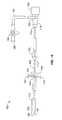
図1は、当該分野において存在することが公知であるような、管状ハブ14に結合された導入器シース12を備える、標準的な単一ポートのカテーテルアセンブリ10を図示する。側部ポート16は、ハブ14および導入器シース12と流体連絡しており、そして生理食塩水または他の流体をカテーテルアセンブリ10に導入するための、弁20および取付具22に接続された管18を有する。止血弁24は、ハブ14に結合され、そして導入器シース12の軸26上に配置され、そしてガイドワイヤ、カテーテルおよび他の介入デバイス(図示せず)の、ハブ14への密封可能な導入を可能にする。 FIG. 1 illustrates a standard single
図2〜図4は、本発明の実施形態である、近位結合器アセンブリ30を、平面図、断面図、および斜視図でそれぞれ図示する。示される実施形態において、Y字型のハブ本体32は、導入器シース取付具34を備えて構成され、この取付具は、Y字型ハブ本体32の遠位端36に外側り部35、およびハブ本体32の近位端40に主要アダプター取付具38を有する。例示的な実施形態において、主要アダプター取付具38は、止血弁(図8に示される)と嵌合する。主要分枝42は、軸46と整列して導入器シース取付具34および主要止血アダプター取付具38(これもまた、軸46上で整列する)を流体的に接続する、管状主要チャネル44を有する。例として、限定ではなく、主要チャネル44は、6フレンチのガイドカテーテル(図示せず)を収容しうる.側部ポート取付具48は、主要分枝42上に位置決めされ、そして主要チャネル44に流体的に接続される。第二の分枝50は、管状分枝チャネル52を有し、このチャネルは、予め決定された移行角βで、主要チャネル44と交差する。二次分枝50の近位端54は、二次取付具56を有する。有利な実施形態において、二次取付具56は、Touhy Borst弁(図8に示される)と嵌合するように適合される。本実施形態において、チャネル制限部58が、導入器シース取付具34に成形される。Y字型ハブ本体32は、一片に成形されても、複数の片から組み立てられてもよい。1つの実施形態において、(図示されない)側部ポート取付具48は、図1〜図3において主要分枝42上に示されるものと類似の様式で、二次分枝50上に配置される。 2-4 illustrate a
ここで図5〜図7を参照すると、減少した体積の近位結合器アセンブリ60の別の有利な実施形態が、平面図、断面図、および斜視図でそれぞれ示される。Y字型ハブ本体62は、減少したサイズの主要分枝64および減少した体積の主要チャネル66と適合される。二次分枝68および二次チャネル70もまた、減少した体積を提供する。遠位端36における導入器シース取付具34および側部ポート取付具48は、図2〜図5のものと同じである.主要分枝64の遠位端40における止血アダプター取付具72は、減少した体積の作動のために適合される。二次分枝68の近位端54における二次取り付け具74もまた、減少した体積での作動のために適合される。 5-7, another advantageous embodiment of a reduced volume
図8は、導入器シース76の近位端75がY字型ハブ本体32の導入器シース取付具34に結合された、図2〜図4に記載されるような近位結合器アセンブリ30を図示する。導入器シースは、導入器シース取付具34の上にフィットされ、そしてリブ35(図2〜7に示される)によって固定される。導入器シース76の遠位端77は、接頭円錐形状に適合され、導入器シースの挿入および前進を補助する。1つの様式において、導入器シースの遠位端77は、脈管拡張器を収容するようにさらに適合される。別の様式において、導入器シースの遠位端77は、放射線不透過性マーカー(図示せず)とさらに適合される。例として、限定ではなく、導入器シースは、約10フレンチまでの大きさにされ得、そして約8フレンチであり得る。有利な実施形態において、導入器シースは、長さ約30cmから長さ焼く45cmである。流体取付具78および流体弁80(例えば、コック弁)が、流体管82を用いて側部ポート48に接続される。1つの様式において、生理食塩水溶液が、流体弁80を通して流体取付具78に導入され、そしてY字型ハブアセンブリ32に入る。止血弁84は、主要アダプター取付具38に結合される。Touhy Borst弁86は、二次取付具56に結合される。止血弁84、Touhy Borst弁86および導入器シース76が取り付けられた、近位結合器アセンブリ30が、キットとして構成され得ることが、理解されるべきである。Touhy Borst弁86は、ハブ本体32の主要分枝に加えて、またはこの主要分枝の代わりに配置され得、そして同様に、止血弁84もまた、側部分枝50に加えて、またはこの側部分枝の代わりに配置され得ることもまた、理解される。同様に、側部ポート48ならびに付随する流体管82、流体弁80、および流体取付具78は、Y字型ハブ本体32の側部分枝50に加えて、またはこの側部分枝の代わりに配置され得ることが、当業者によって理解され得る。 FIG. 8 illustrates a
図9は、図8に示されるような近位結合器の別の実施形態を図示し、ここで、近位結合器アセンブリ90は、Yハブアセンブリ92上で、二次分枝94と導入器シース取付具96との間に位置決めされた、側部ポート48を有する。近位端75および遠位端77を有する導入器シース76は、導入器シース取付具96において、Y字型ハブアセンブリ92に結合されて示される。 FIG. 9 illustrates another embodiment of a proximal coupler as shown in FIG. 8, where the
図10は、挿入前の流体送達しステム100を図示する。流体薬剤注入デバイス102(創造で示される)が、合成管の遠位端104上に配置され、そして送達シース110の遠位端108内で圧縮される。例として、限定ではなく、送達シース110は、直径が約6フレンチ〜約8フレンチ、および長さが約15cmであり得る。別の実施形態において、合成管は、ニッケル−チタン合金から作製される。トルクハンドル112が、合成管106に、合成管106上の近位位置114において結合される.流体注入ポート116は、合成管106の近位端118に位置決めされる.流体注入ポート116は、流体注入のためのアダプター120に結合される。側部ポート取付具122は、管124に結合され、そしてさらに、流体弁126および流体取付具128に結合される。例示的な実施形態において、流体注入ポート116は、ルアー取付具のために適合される。別の例示的な実施形態において、側部ポート取付具122は、生理食塩水溶液を注入するために使用される。 FIG. 10 illustrates a
送達シースハンドル130は、送達シース110の近位端132において位置決めされ、そしてしっかりと取り付けられる。送達シースハンドル130は、送達ハンドルタブ132および送達ハンドルキャップ136をさらに備える。例示的な実施形態において、送達シースハンドル130は、送達ハンドルキャップ136が取り外され、そして送達ハンドルタブ134が引き離される場合に、2つの部品に対称的に分解するように構成される。例として、限定ではなく、剛性管106の遠位端104は、両側カテーテル、流れ偏向器、および流体を主要な血管または1つ以上の分枝血管に注入するように構成された他のデバイスに結合されるように、構成されうる。例として、限定ではなく、剛性管106の遠位端104は、放射線不透過性マーカーまたは他の診断デバイスと結合されて、位置決めを補助し得る。 Delivery sheath handle 130 is positioned and securely attached at
図11Aおよび図11Bは、図8に先に示されたようなY字型ハブアセンブリ30に挿入された、図10に示されるような流体送達システム100を図示する。Y字型ハブアセンブリ30は、明白にするために省略されている。図11Aにおいて、送達シース110は、Touhy Borst弁86を通し、分枝チャネル52(図3)を通して、送達カテーテル110(図10を参照のこと)がチャネル制限部58(図3を参照のこと)に対して止まるまで、挿入される。力140が、トルクハンドル112の遠位方向に付与されて、剛性管106を押し、送達管110に通す。流体薬剤注入デバイス102(図10を参照のこと)は、導入シース76内へと遠位に移動する。 11A and 11B illustrate a
図11Bにおいて、合成管106は、導入シース76を通して進められており、そして図10に示される流体薬剤注入デバイス102は、導入シース76内に展開される。1つの実施形態において、導入器シース76の遠位端77は、図10に示される流体薬剤注入デバイス102を展開する前に、腎臓動脈(図12に示される)の上に位置決めされる。別の実施形態において、導入器シース76の遠位端77は、近位方向に引き込まれ、一方で、図10に示される流体薬剤注入デバイス102は、腎臓動脈の近位に位置決めされたままである。送達シース110は、Y字型ハブアセンブリ32の主要チャネル44(図3を参照のこと)から引き込まれて、医療介入デバイス(図12を参照のこと)が、主要チャネル44(図3を参照のこと)を通り、導入器シース76を通り、そして側部剛性管106に沿ってさらに進むために、止血弁84に入ることを可能にする。1つの様式において、送達シース110は、流体薬剤デバイス102を導入器シース76内で位置決めした後に、Y字型ハブアセンブリ32から取り除かれる。1つの例示的な実施形態において、送達シース110は、分離を容易にするためにその周囲上で約180°離れて位置する2つの薄い壁を備えて押し出し成形される。1つの様式において、送達シースハンドル130は、送達ハンドルキャップ136(図10を参照のこと)を取り外し、そして送達ハンドルタブ134を内向きに押すことによって、2つに分離される。送達シースは、送達タブ134を引き離すことによって、分離され得る。例として、限定ではなく、送達シース110は、引き裂くことによって分離し、そして取り外す前に、Touhy Borst弁86を通して完全に取り外され得る。導入器シース76および流体送達システム100を一緒に備える近位結合器アセンブリ30は、キットとして構成され得ることが理解される。 In FIG. 11B, the
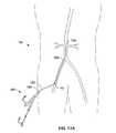
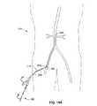
図12は、2つの局所流体送達システム152、154、および大動脈系158内の介入カテーテル156を備える二重Y字型近位カプラー150の様式化された図である。局所送達システム152、154の詳細は、図11Aおよび11Bに示され、明瞭さのためにここでは省略する。二重Y字型近位カプラー150は、図2〜図4に示される近位カプラー30と同様に構成されるが、別の分枝ポートが加えられる。第2の分枝160は、右腎動脈162での薬物注入のための局所流体送達システム152を収容する。第3の分枝164は、左腎動脈166における薬物注入のための局所流体送達システム154を収容する。介入カテーテル156は、止血弁168を介して二重Y字型近位カプラー150に入る。導入シース170は、局所流体送達システム152、154およびカテーテル156を同時に収容するような大きさである。図12は、二重Y字型近位カプラーの同じ側に第2の分枝160および第3の分枝164を示す;しかし、これらは、反対側または別の有利な構成で位置づけられ得る。限定ではなく例として、局所流体送達システム152、154の断面は、卵形形状であり得る。限定ではなく例として、二重Y字型近位カプラー150は、ガイドワイヤ、診断カテーテル、フローダイバーターおよび注入アセンブリのような医療デバイスの幅広い混合物を、導入器シース170を通して大動脈系158のような脈管系内に進めるために適合され得る。 FIG. 12 is a stylized view of a double Y-shaped
図13Aは、図11Aに示されるものと類似の、カプラーアセンブリ180として示される、流体送達システムが装着された近位カプラーを示す。カプラーアセンブリ180は、遠位端184および近位端186を備える導入器シース182に連結され、大腿または腸骨動脈アクセス点192を介して、患者190の大動脈系188に挿入される。図11Aおよび11Bにおいて先に記載されるように、近位カプラーアセンブリ180の詳細は、明瞭さのために省略されている。 FIG. 13A shows a proximal coupler fitted with a fluid delivery system, shown as a
図13Bにおいて、導入器シース182は、流体薬剤注入デバイス102(図10に示される)を展開し、そして移行ゾーン196を作り出すために、方向194へと引っ張られている。結果として、導入器シース182の近位端186は、移行ゾーン196の長さに対応する長さだけ、挿入点192から外側に引かれる。介入カテーテル198は、導入器シース182が引っ張られた位置にある場合に、流体薬剤注入デバイス102の遠位の標的医療位置(図示せず)に達するように、移行ゾーン196の長さを延ばさなければならない。 In FIG. 13B,
図14Aは、調節可能な導入器シース204が遠位端206、近位端208および調節可能な近位部分210を延長した状態で有する、図13Aに近位カプラー流体送達アセンブリ180を示す。調節可能な導入器シース204の調節可能な近位部分210は、「アコーディオン」様式で、全体の長さを圧縮し得る、波形をつけた可撓性材料から構成される。 FIG. 14A shows a proximal coupler
図14Bは、導入器シース204の遠位端206の方向194への引っ張りが、移行ゾーン196を作り出す流体薬剤注入デバイス102を展開した後のような、圧縮状態の調節可能な近位部分210を有する図14Aを示す、調節可能な導入器シース204を示す。調節可能な導入器シース204の近位端208は、移行ゾーン196の長さの調節可能な近位部分210の圧縮のため、挿入点192から離れるように引っ張られていない。介入カテーテル212は、適切な長さであり、流体薬剤注入デバイス102の標的医療位置(図示せず)に達する。 FIG. 14B shows the adjustable
図15Aは、図14Aに示されるように、調節可能な近位部分210が延長した状態で近位端208に接続された調節可能な導入器シース204を備える近位カプラーアセンブリ180のクローズアップを示す。低いプロフィールの外部保持チューブ220は、調節可能な近位部分210のプレート222の上にきちんと位置づけられ、プレート222が外側に折り畳まれることを妨げ、従って、調節可能な近位部分210が短縮することを妨げる。 FIG. 15A shows a close-up of a
図15Bは、外部保持チューブ220が調節可能な近位部分210から除かれた、図15Aに示される調節可能な導入器シース204を示す。プリーツ222は、外側に折り畳まれ得、調節可能な部分210が、方向194に短縮し得る。制限ではなく例示として、外部保持チューブ220は、導入器シース204の別の部分にスライドし得るかまたは引きはがす(tear−away)様式で取り除かれ得る。 FIG. 15B shows the
図16Aは、図14Aに示されるような拡張状態にある、近位端208にて調節可能な導入器シース204に結合しており、調節可能な近位セクション210を備える、近位結合体アセンブリの別の実施形態を示す。内部支持チューブ224が、調節可能な近位セクション210中に配置され、その結果、内部支持チューブ224の外径は、プリーツ222が内側に折畳むのを防ぐ。 16A is coupled to an
図16Bは、図16Aにおける調節可能な導入器シース204を示し、内部支持チューブ224が、調節可能な近位セクション210から取り外されている。プリーツ22が、内側に折畳み、調節可能なセクション210が接触するのを可能にする。あるいは、内部支持チューブ224は、調節可能な近位セクション210の外部操作を介して導入器シース204の別のセクション中に配置され得る(示さず)。 FIG. 16B shows the
図17Aは、調節可能な導入器シース204の近位端208に結合している近位結合器アセンブリ180の別の実施形態を示す。導入器シース204の調節可能なセクション210は、プリーツ222、遠位端226および近位端228を備える。複数の調節ワイヤ230が、調節可能なセクション210の遠位端226にて導入器シース204に結合している。明確にするために、ただ1つの調節ワイヤ230しか、示さない。ロッキングリング232が、調節可能なセクション210の近位端228と、調節可能な導入器シース204の近位端208との間に、かつ調節ワイヤ230の上に、配置される。ロッキングリング232は、半径方向内向きの力または他の手段により調節可能なワイヤ230がスライドすることから固定し、それにより、調節可能なセクション210を展開状態で保持するような構成である。 FIG. 17A illustrates another embodiment of a
図17Bは、図17Aに示される調節可能な導入器シース204の近位端208に結合している近位接続器アセンブリ180を示す。ロッキングリング232は、拡張されるか、または開放され、それにより、調節可能なワイヤ230が、調節可能なセクション210を圧縮させる方向194に近位にスライドすることを可能にする。ロッキングリング232はまた、止め金またはクランプ(示さず)を用いて適合されて、調節可能なワイヤ230を固定した後に開放し得る。 FIG. 17B shows the
図18は、局所流体送達システム252およびカテーテルアセンブリ254に結合された、近位結合器アセンブリ254を用いる本発明の別の局面の様式図である。図19Aおよび図19Bは、近位接続器アセンブリ250の長手方向断面をさらに示す。近位接続器アセンブリ250は、図2〜図5に示されるものと類似する、Tハブ本体256を備え、遠位ポート260、近位ポート262、および二次ポート264に、密封可能なアダプター258(例えば、Touhy Borst弁)を備える。Yハブ本体256は、遠位ポート260と近位ポート262とを接続する主チャネル266(図19Aに示される)と、二次ポート264と主チャネル266とを接続する二次チャネル268(図19Aに示される)とを備える。 FIG. 18 is a schematic diagram of another aspect of the present invention using a
局所流体送達システム252は、ハイポチューブ270の遠位端に、流体薬剤注入器デバイス102(図13Bに示される)。可撓性送達シース272は、近位ハンドル274を備える。可撓性送達シース272は、ハイポチューブ274の遠位端および中部セクションを囲む。ハイポチューブ270の近位端は、図10に以前に示されたように、流体送達用に構成される。 Local
カテーテルアセンブリ254は、図1に以前に示されたものと類似する。剛性チューブ276が、カテーテルマニホルド278(これは、カテーテル280を受容するように構成されている)に接続され、近位接続器アセンブリ250に近位ポート262を通って合成チューブ276を用いて接続される。カテーテル280は、近位ポート260および止血弁282を通って、カテーテルマニホルド278に入る。1つの有益な実施形態において、カテーテル280は、直径6Frおよび長さ約100cmである、ガイドカテーテルである。 The
図18において、可撓性送達シース272が、密封可能なアダプター258を通って二次ポート中に挿入され、遠位ポート260を通って前進されて、送達シースの遠位端が自動脈の近位にある位置へと到達する。局所流体送達システム252のハイポチューブ270は、流体薬剤注入器デバイス(図13Bに示される)が腎動脈付近に適所にあるまで、遠位に前進される。送達シース272は、ハンドル274を引くことにより、近位接続器アセンブリ250および二次ポート264を通って引き込まれて、図13Bに以前に示されたように、流体薬剤注入器デバイスの近位に開放移行帯を生成する。1つの有益な様式において、送達シースは、約10cm引き込まれる。二次ポート264にある密封可能なアダプター258は、送達シース272およびハイポチューブ270を適所に強固に保持するように締められる。 In FIG. 18, a
図19Aにおいて、カテーテルアセンブリ254の剛性チューブ276が、近位結合器アセンブリ250の近位ポート262に挿入される。封着可能なバルブ258が、明瞭にするために取り除かれている。剛性チューブ276は、遠位先端284に位置付けられ、遠位先端は、近位ポート262を通って、主要チャネル266内に進められる。 In FIG. 19A, the
図19Bにおいて、位置付けられた剛性チューブ276の遠位先端284は、さらに遠位に進められ、主要チャネル266と二次チャネル268の分枝において送達シース272を穿孔する。剛性チューブ276の遠位先端284は、ハイポチューブ270の隣の送達シース272の内側管腔内に位置付けられて示される。近位ポート262にある封着可能なアダプター258(図18に示される)は、剛性チューブ276を適所にしっかりと固定するように締められる。次いで、カテーテル280は、止血バルブ282、カテーテルマニホルド278および剛性チューブ276(図18に示される)によって遠位に進められ、次いで、送達シース272を通り、さらなる医療介入のために送達シース272の遠位端から外に出る。 In FIG. 19B, the
図20は、平面図であり、図21は、流体送達デバイスに隣接するカテーテルを挿入する別の様式の切断図であり、ここで、Yアセンブリ300は、導入器シース304に係合された遠位端302、止血バルブ308を備える近位ポート306、および分枝ポート上にTouhy Borstバルブ312を備える分枝ポート310を有する。ステンレス鋼のような堅固な材料から作製された、近位中間セクション316および近位端318を有する送達シース314の近位部分は、導入器シース304内に遠位端(示さず)を備える止血(heomostasis)バルブ308内に挿入される。送達シース314の近位端318は、図10において以前に記載されたように、局所流体送達システム320に係合される。局所流体送達システムのさらなる詳細は、明瞭にするために、ここでは省略される。ハイポチューブ322は、局所流体送達システム320上のTouhy Borstバルブ324を通って送達シース314内を遠位に延びる。送達シース314の近位中間セクション316は、分枝ポート310を通って導入されるガイドカテーテル328を適合するように構成された、所定の間隔で間を空けた、プレカット穴326を有する。好ましい実施形態において、ガイドカテーテル328は、長さ約100cmおよび直径約6Frである。導入器シース304は、図13Aにおいて以前に記載されたように、大動脈系内に挿入される。図13Bにおいて以前に示されるような、流体薬剤注入デバイスの展開は、送達シース314を所望の位置まで進め、送達シース314を通してハイポチューブ322を進めて流体薬剤注入デバイス102を位置付けすることによって達成される。図13Bにおいて以前に示されるように、流体薬剤注入デバイスは展開され、送達シース314が移行帯を形成し得るように引き戻され、そして、1つの実施形態において、送達シース314は、約10cmである。Yハブアセンブリ300は、好ましいプレカット穴326’(図21に示される)が、Yハブアセンブリ300の分枝ポート310と並ぶまで、送達シース314の近位部分上を、遠位に進めされる。ガイドカテーテル328が、分枝ポート310上のTouhy Borstバルブ312を通して導入され、送達シース320内の好ましい穴326’を通して挿入される。 FIG. 20 is a plan view and FIG. 21 is a cutaway view of another manner of inserting a catheter adjacent to a fluid delivery device, where the
ガイドカテーテル328は、側部ハイポチューブ322に沿って送達シース314を通して遠位に進められ、最終的に、図13Bにおいて以前に記載されたように、標的部位まで進めされる。Yハブアセンブリ300は、医療手順の間に、送達シース314内の全てのプレカット穴326を、Yハブアセンブリ300の内側および止血バルブ308の遠位に封着されたままにするように、近位にポート306を延ばすことによってさらに変更され得る。 The
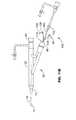
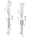
図22は、近位結合器アセンブリ、および図11Bに示すような流体送達アセンブリのさらなる実施形態を例示する。腎臓治療システム350は、シースシステム352、脈管拡張器354、および二股の腎臓カテーテル368を備える流体送達システム356を備える。図2〜図4において、以前に示されるような、チャネル、生理食塩水システムおよび取付具の詳細は、明瞭にするために省略される。導入器シースシステム352は、図3において以前に示されるような種々の内部構造体を備え付けられた、図2〜図4において以前に示されるようなYハブ本体360を有する。Yハブ本体360は、近位端366に止血バルブ362を、第二の端370にTouhy Borstバルブ368を有する。Yハブ本体360の遠位端372は、導入器シース376の近位端374に係合されている。導入器シース376は、先端を切り取った円錐形状を有する遠位先端378および放射線不透過性のマーカーバンド380を有する。1つの実施形態において、導入器シー376は、PTFE材料の内側ライナー、内側コイルワイヤ強化剤および外側ポリマージャケットで構成される。導入器シース376は、近位端374から遠位先端378まで測定した、所定の長さLを有する。 FIG. 22 illustrates a further embodiment of a proximal coupler assembly and a fluid delivery assembly as shown in FIG. 11B. The
遠位端380および近位端382を備える脈管拡張器354は、ガイドワイヤ(示さず)のための中央管腔を備える、ポリマー(例えば、押出し)チューブである。遠位端380は、テーパ型の円錐形状に適合されている。近位端382は、Luer取付器384に係合されている。
流体送達システム356は、堅固なチューブ386、トルクハンドル388および、図11Aおよび図11Bにおいて以前に記載されたような近位ハブ390を有し、遠位端392に二股カテーテル358が係合されている。二股カテーテル358は、形状記憶材料の2つの遠位拡張部393、394を有する。各遠位拡張部の393、394の遠位先端395、396は、それぞれ、複数の流体ポート(示さず)および放射線不透過性のマーカーバンド397を有する。ポリマーチューブ398は、遠位拡張部393および394の近位に位置付けられ、放射線不透過性のマーカーバンド400を有する。流体送達システム356の近位ハブ390は、堅固なチューブ386と流体係合されている、流体薬剤を注入するためのLuer取付器402を有する。 The
単一の管腔引き剥がし送達シース404は、遠位端406、近位端408を有し、スライドして、堅固なチューブ386を覆う。送達シース404は、トルクハンドル388と二股カテーテル358との間に位置付けられる。遠位端406は、図3において以前に示されるような、Yハブ本体の主要チャネルの遠位端内のチャネル制限と嵌合するように適合された形状および外径を有する。送達シース404の近位端408は、2つのハンドル412および引き剥がしキャップ414を備えるハンドルアセンブリ410に係合される。 The single lumen tear-off
拡張器354は、遠位端380が導入器シース376の遠位先端378から押出されて、滑らかな外側の円錐形状を形成するまで、第二のポート370上をTouhy Borstバルブ368を通って挿入される。導入器シース376の遠位先端378は、腎動脈(示さず)の近くの大動脈系内に位置付けられる。拡張器354が取り外され、二股カテーテル3358の遠位拡張部393および394が送達シース404内に入るまで、外側シース404を遠位にスライドさせることによって、流体送達デバイス356が調製される。送達シース404の遠位端406は、Touhy Borstバルブ368内に挿入され、図3に示されるYハブ本体の主要チャネル内の制限まで進められる。二股カテーテル358は、導入器シース376内を遠位に進められる。引き剥がし送達シース404は、図11Bにおいて以前に示されたように、Touhy Borstバルブ368を通して引き出され、取り除かれる。二股カテーテル358は、導入器シース376の遠位先端378の外側を遠位に進められ、そして、遠位拡張部393および394は、その予め形成された形状まで拡張して、腎動脈(示さず)にカニューレを挿入する。 The
上記の種々の実施形態により提供される特定の利点にも関わらず、多くの状況における治療薬剤の二側方局所腎臓送達に適していると考えられる、本発明の特定の局面をさらに例示するために、図22において以前に示されたような、腎臓治療システム全体の1つの特に高度に有利な実施形態が、以下のように提供される。 In order to further illustrate certain aspects of the present invention, which may be suitable for bilateral local renal delivery of therapeutic agents in many situations, despite the particular advantages provided by the various embodiments described above. In turn, one particularly highly advantageous embodiment of the entire kidney treatment system, as previously shown in FIG. 22, is provided as follows.
図2〜図4において以前に示されたようなYハブ本体は、透明な物質から作製され、主要チャネルおよび主要チャネルを横切る二次チャネルを備え付けられている。主要チャネルの遠位端は、図3に示すようなチャネル制限と適合している。Yハブ本体は、遠位端に導入器シース取付器を有し、かつ、Yハブ本体の主要チャネル内への生理食塩溶液の導入のためのポートを有する。止血バルブは、Yハブ本体の主要分枝上の近位取付器に取り付けられ、名目上6フレンチ直径のカテーテルを収容するように構成される。Touhy Borstバルブは、Yハブ本体の二次ポート上の二次取付器に取り付けられる。 The Y hub body as previously shown in FIGS. 2-4 is made of a transparent material and is equipped with a main channel and a secondary channel across the main channel. The distal end of the main channel is compatible with channel restrictions as shown in FIG. The Y hub body has an introducer sheath applier at the distal end and a port for introduction of saline solution into the main channel of the Y hub body. The hemostasis valve is attached to a proximal fitting on the main branch of the Y hub body and is configured to accommodate a nominally 6 French diameter catheter. The Touhy Borst valve is attached to a secondary fixture on the secondary port of the Y hub body.
導入器シースは、Yハブ本体の導入器シース取付器に係合され、TFE材料の内側ライナー;内側コイルワイヤ強化剤および外側ポリマージャケットで構成される。名目上8フレンチの導入器シースは、約0.116インチの内径と約0.138インチの外径を有する。遠位先端は、先を切り取った円錐のような形状であり、脈管拡張器の遠位先端と適合され、放射線不透過性のマーカーバンドを有する。導入器シースの近位端は、外側ポリマージャケットのみから構成され、Yハブ本体上の導入器シース取付器に係合するようにフレア型である。1つの高度に有利な実施形態において、複数の導入器シースが、腎臓治療システムに提供されて、異なる生体組織を収容する。図22に示すような、約30cm、約35cm、約40cm、および約45cmの名目上の使用可能な長さLを有する導入器シースが、代表的に含まれるが、他の適切な長さもまた提供され得る。本発明の例において、異なる長さの導入器シースが、各々、一体型の導入器シースシステムとしてY本体ハブに係合されるが、このシステムは、後の組立てのために、別々に梱包および販売され得る。 The introducer sheath is engaged with the introducer sheath applicator of the Y hub body and is comprised of an inner liner of TFE material; an inner coil wire reinforcement and an outer polymer jacket. A nominal 8 French introducer sheath has an inner diameter of about 0.116 inches and an outer diameter of about 0.138 inches. The distal tip is shaped like a truncated cone, is fitted with the distal tip of the vasodilator, and has a radiopaque marker band. The proximal end of the introducer sheath is composed solely of the outer polymer jacket and is flared to engage the introducer sheath applicator on the Y hub body. In one highly advantageous embodiment, multiple introducer sheaths are provided to the renal treatment system to accommodate different biological tissues. An introducer sheath having a nominal usable length L of about 30 cm, about 35 cm, about 40 cm, and about 45 cm, as shown in FIG. 22, is typically included, although other suitable lengths are also Can be provided. In the present example, different length introducer sheaths are each engaged to the Y-body hub as an integral introducer sheath system, which can be separately packaged and assembled for later assembly. Can be sold.
脈管拡張器は、導入器シースの遠位先端部を腎動脈の近位領域にガイドするために、この腎臓治療システムと共に使用される。脈管拡張器は、約0.040インチの内部管腔を備える遠位端でテーパ加工され、そして直径約0.035インチ〜約0.038インチのガイドワイヤの通路に適合されたポリマー押し出し成形物である。脈管拡張器の長さは、シースの遠位先端部から伸展し、また、適切なY字型ハブ本体の近位ポートの外側に伸展するために、対応する導入器シースの有効長よりも、名目上約11cm長い。脈管拡張器の近位端は、最初に生理食塩水を内部管腔にフラッシングするためのルアー取付具を備える。 Vasodilators are used with this renal treatment system to guide the distal tip of the introducer sheath to the proximal region of the renal artery. The vasodilator is a polymer extrusion tapered at the distal end with an internal lumen of about 0.040 inches and adapted to guidewire passages of about 0.035 inches to about 0.038 inches in diameter. It is a thing. The length of the vasodilator extends from the distal tip of the sheath and exceeds the effective length of the corresponding introducer sheath in order to extend outside the proximal port of a suitable Y-shaped hub body. , Nominally about 11 cm long. The proximal end of the vasodilator includes a luer fitting for initially flushing saline into the inner lumen.
経皮的入口点に対する腎動脈の位置が、診断カテーテルを備えるガイドワイヤおよび当該分野で公知の方法を使用して決められた後に、適切な長さの統合型導入器シースシステムが選択される。脈管拡張器は、Y字型ハブの二次分枝上でTouhy Borst弁を通して導入され、そして導入器シースの遠位先端から脈管拡張器の突出部の遠位先端まで進められて、外側に滑らかな円錐形を生じる。生理食塩水のフラッシングは、Y字型本体上のポート、および脈管拡張器の近位ポートを通して導入される。挿入された脈管拡張器を備える導入器シースは、経皮的アクセス点を通って腎動脈の大動脈へガイドワイヤ上を進められる。導入器シースの遠位先端上のマーカーバンドが、位置決めを補助するために蛍光透視と共に使用され得る。導入器シースの遠位先端が腎動脈に、または腎動脈の近くに位置される場合、脈管拡張器およびガイドワイヤが縮められ、そしてTouhy Borst弁を通してY字型本体から取り外され、一方で、導入器シースはその場にとどまる。 After the position of the renal artery relative to the percutaneous entry point is determined using a guidewire with a diagnostic catheter and methods known in the art, an appropriate length integrated introducer sheath system is selected. The vasodilator is introduced through the Touhy Borst valve on the secondary branch of the Y-shaped hub and advanced from the distal tip of the introducer sheath to the distal tip of the vasodilator protrusion, Produces a smooth cone. Saline flushing is introduced through a port on the Y-shaped body and the proximal port of the vasodilator. An introducer sheath with an inserted vasodilator is advanced over the guide wire through the percutaneous access point to the aorta of the renal artery. A marker band on the distal tip of the introducer sheath can be used with fluoroscopy to assist in positioning. When the distal tip of the introducer sheath is located at or near the renal artery, the vasodilator and guidewire are retracted and removed from the Y-shaped body through the Touhy Borst valve, The introducer sheath remains in place.
図11Aに既に示されるように、流体送達システムは、Y字型本体への挿入のために準備される。この実施形態において、流体送達システムは、好ましくはニチノールチュービング製の、遠位端、中央の近位部分および近位端を含めて有効長が約77cmの剛性管を備える。二股カテーテルは、その剛性管の遠位端に接続される。この二股カテーテルの遠位拡張部は、記憶形状を有し、リボンワイヤの内部核を備えるブレード補強したポリマーから作製される。この実施例における各々の遠位拡張部は、放射線不透過性のマーカーを有し、そして遠位先端部またはその近くに2つの注入ポートを備える。各々の遠位拡張部の外径は、名目上約3フレンチである。遠位拡張部の接続部の近位位置において、二股カテーテルが入るポリマー管が存在する。このポリマー管は、二股カテーテルと導入器シースとの相対的な位置決めを補助するために遠位拡張部の接続部の約1cm〜約1.5cm近位に配置される2つの放射線不透過性のマーカーを備える。 As already shown in FIG. 11A, the fluid delivery system is prepared for insertion into a Y-shaped body. In this embodiment, the fluid delivery system comprises a rigid tube having an effective length of about 77 cm including a distal end, a central proximal portion and a proximal end, preferably made of Nitinol tubing. A bifurcated catheter is connected to the distal end of the rigid tube. The distal extension of this bifurcated catheter is made from a blade reinforced polymer having a memory shape and having an inner core of ribbon wire. Each distal extension in this embodiment has a radiopaque marker and comprises two injection ports at or near the distal tip. The outer diameter of each distal extension is nominally about 3 French. At the proximal location of the distal extension connection, there is a polymer tube into which the bifurcated catheter enters. The polymer tube is comprised of two radiopaque radiopaques positioned about 1 cm to about 1.5 cm proximal to the distal extension connection to assist in relative positioning of the bifurcated catheter and introducer sheath. Provide a marker.
流体送達システムは、剛性管の中央の近位部分に接続されたトルクハンドルと、剛性管の近位端に接続された近位ハブとを備える。近位ハブは、流体薬剤を注入するためのルアー取付具と、剛性管に流体的に接続された生理食塩水フラッシングポートとを備える。 The fluid delivery system includes a torque handle connected to the central proximal portion of the rigid tube and a proximal hub connected to the proximal end of the rigid tube. The proximal hub includes a luer fitting for injecting a fluid medicament and a saline flushing port fluidly connected to the rigid tube.
単一の管腔の剥離送達シースは、剛性管をスライドするように入れており、トルクハンドルと二股カテーテルとの間に位置決めされる。送達シースは、遠位端および近位端を含めて、長さが名目上約15cmである。遠位端は、図3に既に示されるように、Y字型ハブ本体の主要チャネルの遠位端にチャネル制限部を備える接合部に適合した形状および外径を有する。送達シースの近位端は、2つのハンドルを備えるハンドルアセンブリに接続される。ハンドルアセンブリは、近位端上に剥離キャップを備え、そして剥離キャップが取り外されハンドルが引き離される場合に、ハンドルアセンブリが2つの部分に分離可能なように構成される。送達シースの周辺プロフィールは、ハンドルが引き離される場合に、縦方向に2つの部分に割れやすくなることに対抗する薄い壁の部分と共に構成される。 A single lumen exfoliation delivery sheath is placed to slide the rigid tube and is positioned between the torque handle and the bifurcated catheter. The delivery sheath is nominally about 15 cm in length, including the distal and proximal ends. The distal end, as already shown in FIG. 3, has a shape and outer diameter adapted to a joint comprising a channel restriction at the distal end of the main channel of the Y-shaped hub body. The proximal end of the delivery sheath is connected to a handle assembly that includes two handles. The handle assembly includes a peel cap on the proximal end and is configured such that the handle assembly is separable into two parts when the peel cap is removed and the handle is pulled apart. The peripheral profile of the delivery sheath is configured with a thin wall portion that counteracts being prone to breaking into two portions in the longitudinal direction when the handle is pulled apart.
流体送達システムは、剛性管近位ハブ中の生理食塩水ポートから二股カテーテルの遠位拡張先端における注入ポートへ生理食塩水溶液をフラッシングすることによって準備される。二股カテーテルは、二股カテーテルの遠位拡張部が送達シース内に完全に入るまで、送達シースハンドルに対してカテーテルを引くことによって送達シース中にロードされる。 The fluid delivery system is prepared by flushing saline solution from a saline port in the rigid tube proximal hub to an injection port at the distal dilation tip of the bifurcated catheter. The bifurcated catheter is loaded into the delivery sheath by pulling the catheter against the delivery sheath handle until the distal extension of the bifurcated catheter is fully within the delivery sheath.
ロードされた二股カテーテルを備える送達シースの遠位端は、Y字型本体の二次ポート上のTouhy Borst弁を通して、遠位端が主要チャネル中のチャネル制限部に収容されるまで挿入される。剛性管のトルクハンドルにおける遠位力は、二股カテーテルを導入器シース中に進め、好ましくは、遠位拡張部が剥離送達シースの完全に外側かつ導入器シース中にあることを確実にするために、導入器シース中に約15cm(剥離送達シースのおおよその長さ)進める。 The distal end of the delivery sheath with the loaded bifurcated catheter is inserted through the Touhy Borst valve on the secondary port of the Y-shaped body until the distal end is received in the channel restriction in the main channel. The distal force at the rigid tube torque handle advances the bifurcated catheter into the introducer sheath, preferably to ensure that the distal extension is completely outside the peel delivery sheath and in the introducer sheath. Advance about 15 cm (approximate length of release delivery sheath) into the introducer sheath.
図11Bで以前記載したように、引き裂き送達シースは、送達シースハンドルアセンブリ上の近位位置において引くことによってY字型ハブ本体から引き出される。送達シース引き出しの間、二股カテーテルは、導入シースに留まる。送達シースの遠位端がYハブ本体から取り除かれる場合、剛性な管にTouhy Borst弁が締められ、流体の損失を防ぐ。引き裂きキャップが、送達シースハンドルアセンブリから除去され、そしてこのハンドルは、送達シースを長手軸方向に引き裂いて分離されて二つになり、剛性の管から除去され、廃棄される。 As previously described in FIG. 11B, the tear delivery sheath is withdrawn from the Y-hub body by pulling in a proximal position on the delivery sheath handle assembly. During delivery sheath withdrawal, the bifurcated catheter remains in the introducer sheath. When the distal end of the delivery sheath is removed from the Y hub body, a Touhy Borst valve is tightened on the rigid tube to prevent fluid loss. The tear cap is removed from the delivery sheath handle assembly, and the handle is split into two by tearing the delivery sheath longitudinally and removed from the rigid tube and discarded.
二股カテーテルは、Y字型ハブ本体に対し、トルクハンドルでの剛性の管の遠位運動により導入シースの遠位チップに進められる。蛍光顕微鏡の手引きを使用して、二股カテーテルは、導入シースの遠位チップの外に進められる。二股カテーテルは、トルクハンドルを通じて操作され、導入シースは同時に引き出され、そして遠位伸長部は、大動脈内でその記憶形状に曲がり、腎動脈にカニューレ挿入される。一旦遠位伸長が導入シースの遠位チップの外に完全に伸長して腎動脈内に配置されると、導入シースの遠位チップは、二股カテーテルのポリマー管上のマーカーバンドの少なくともすぐ近位に引き出され、介入カテーテルの進行を可能にし、一方、二股カテーテルは、その場に留まる。導入シースが配置されるのに伴い、Touhy Borst弁が締められ、導入シース内の二股カテーテルのさらなる運動を防ぐ。 The bifurcated catheter is advanced to the distal tip of the introducer sheath by distal movement of the rigid tube with a torque handle relative to the Y-shaped hub body. Using the fluorescence microscope handbook, the bifurcated catheter is advanced out of the distal tip of the introducer sheath. The bifurcated catheter is manipulated through the torque handle, the introducer sheath is withdrawn simultaneously, and the distal extension is bent into its memory shape within the aorta and cannulated into the renal artery. Once the distal extension is fully extended out of the distal tip of the introducer sheath and placed in the renal artery, the distal tip of the introducer sheath is at least immediately proximal to the marker band on the polymer tube of the bifurcated catheter And the bifurcated catheter stays in place while allowing the interventional catheter to proceed. As the introducer sheath is deployed, the Touhy Borst valve is tightened to prevent further movement of the bifurcated catheter within the introducer sheath.
導入シースは、縫合されるか、またはそうでなければ経皮入り口部位もしくはその近くで制御され、その後の手順の間のシース運動を妨げる。液体薬剤は、ここで流体送達システムの近位ポートを通して、剛性の管および腎動脈内へ、図22で示す二股カテーテルと類似の二股カテーテルを通じて送達される。 The introducer sheath is sutured or otherwise controlled at or near the percutaneous entrance site to prevent sheath movement during subsequent procedures. The liquid drug is now delivered through a bifurcated catheter similar to the bifurcated catheter shown in FIG. 22 through the proximal port of the fluid delivery system and into the rigid tube and renal artery.
医療介入手順(冠状動脈手順)は、Y字型ハブ本体の近位取り付け具上の止血弁を介した、適切なガイドワイヤおよびカテーテルの挿入によって開始される。この例において、名目上6つのフレンチカテーテルは、導入シースを通り、剛性チューブの側に沿って、有意な抵抗無しに進められる。 The medical intervention procedure (coronary artery procedure) is initiated by the insertion of an appropriate guide wire and catheter through a hemostasis valve on the proximal fitting of the Y-shaped hub body. In this example, nominally six French catheters are advanced through the introducer sheath and along the side of the rigid tube without significant resistance.
医療介入が完了した場合、介入カテーテルおよびガイドワイヤを引き出し、そして止血弁を通ってY字型ハブ本体から除去される。液体薬剤送達は、しばしば停止される。Touhy Borst弁は、緩められ、そして剛性チューブのトルクハンドルは、Y字型ハブ本体に対して近位に引かれ、二股カテーテルの遠位伸長を腎動脈の外に引き出し、そして導入シースに引き入れる。導入シースは、経皮入口点から引き出され、そして入口点は、標準的医療手順により閉じられる。 When the medical intervention is complete, the interventional catheter and guidewire are withdrawn and removed from the Y-hub body through the hemostasis valve. Liquid drug delivery is often stopped. The Touhy Borst valve is relaxed, and the rigid tube torque handle is pulled proximally with respect to the Y-shaped hub body to pull the distal extension of the bifurcated catheter out of the renal artery and into the introducer sheath. The introducer sheath is withdrawn from the percutaneous entry point, and the entry point is closed by standard medical procedures.
本発明について、本明細書中の種々の実施形態は、腎臓を指向する処置および治療(例えば、ヨウ素標識した造影物質を用いる診断手順から生じるX線コントラスト腎症(RCN)の予防)において有用である。RCN発症の危険度が高いと同定されている介入手順を受ける患者についての予防処置方法として、腎臓への局所的な治療剤の送達に基づき、一連の処置スキームが、開発されている。薬剤の中で、生理食塩水(NS)および血管拡張剤パパベリン(PAP)およびフェノルドパム(fenoldopam)メシレート(FM)が、このような処置のために同定されている。 For the present invention, the various embodiments herein are useful in kidney-directed treatments and therapies (eg, prevention of X-ray contrast nephropathy (RCN) resulting from diagnostic procedures using iodine-labeled contrast material). is there. A series of treatment schemes has been developed as a prophylactic treatment method for patients undergoing interventional procedures that have been identified as at high risk of developing RCN, based on the delivery of local therapeutic agents to the kidney. Among the drugs, saline (NS) and the vasodilators papaverine (PAP) and fenoldopam mesylate (FM) have been identified for such treatment.
フェノルドパムについての認可された使用は、迅速であるが、急速に可逆的ではなく、血圧低下が必要である場合の、高血圧の入院介入処置のための使用である。フェノルドパムは、約0.01mcg/kg/分〜約0.5mcg/kg/分IVと同じ程度の低さの全身的投薬において、腎血管拡張を引き起こし、そして腎皮質と腎髄質との両方に対し血流を増加する。この生理学に起因して、フェノルドパムは、危険性の高い外科的手順およびコントラスト腎症のような虚血性発作からの腎臓の保護のために使用され得る。約0.01〜約3.2mcg/kg/分、または腎動脈(または腎臓)につき約.005〜約1.62mcg/kg/分の投薬は、本発明の実施形態の殆どの適用のために好適であると考えられる。上述のように、多くの場合、これは、開始用量を選択し、患者の最大耐用前進用量を決定するために上下に滴定することにおいて、有用であり得る。しかし、近年のデータは、コントラスト腎症の予防において約0.2mcg/kg/分のフェノルドパムは、約0.1mcg/kg/分よりも大きな効率を有することが示唆されており、この用量が好ましい。 Approved use for fenoldopam is for use in hospitalized interventions for hypertension when it is rapid but not rapidly reversible and blood pressure reduction is required. Fenoldopam causes renal vasodilation at systemic dosages as low as about 0.01 mcg / kg / min to about 0.5 mcg / kg / min IV and to both the renal cortex and renal medulla Increase blood flow. Due to this physiology, fenoldopam can be used for high-risk surgical procedures and protection of the kidney from ischemic attacks such as contrast nephropathy. About 0.01 to about 3.2 mcg / kg / min, or about .about. Per renal artery (or kidney). A dosage of 005 to about 1.62 mcg / kg / min is considered suitable for most applications of embodiments of the present invention. As mentioned above, in many cases this can be useful in selecting a starting dose and titrating up and down to determine the patient's maximum tolerated advance dose. However, recent data suggest that about 0.2 mcg / kg / min of fenoldopam has an efficiency greater than about 0.1 mcg / kg / min in the prevention of contrast nephropathy, this dose being preferred .
腎臓動脈に、両側に送達される通常の生理食塩水の用量レベルは、実験的に設定され得るか、または、滴定によって決定されるように、有利に変更され得る。カテーテルまたは注入ポンプ設計は、送達され得る液体の量に現実的な制限を与え得る;しかし、可能な限り多く与えることが望まれ、1時間あたり、約2Lもしくは1Lまでのレベル(平均約180lbの患者に、約25cc/kg/時間)、または腎臓当たり12.5cc/kgまでのレベルが有益であり得ることが企図される。 The normal saline dose level delivered bilaterally to the renal artery can be set experimentally or can be advantageously varied as determined by titration. Catheter or infusion pump designs can impose practical limits on the amount of liquid that can be delivered; however, it is desirable to provide as much as possible, and levels up to about 2 L or 1 L per hour (average of about 180 lbs) It is contemplated that patients may benefit from levels up to about 25 cc / kg / hour), or up to 12.5 cc / kg per kidney.
両側カテーテルを介した約4mg/分まで、または約2mg/分までのパパベリンの局所的投薬は、動物試験において安全であることが示されていて、カテーテルへの約2mg/分および約3mg/分の局所的腎臓投薬は、ヒト被験体において、腎臓血流速度を増加させること、または、動脈もしくは腎臓については、約1mg/分〜約1.5mg/分の投薬が、血流速度を増加させることが示されている。従って、パパベリンの局所的両側腎臓送達が、既に危険因子(例えば、高い血清クレアチニンのベースライン、糖尿病または他の損傷した腎機能の証拠)が存在する患者におけるRCNの危険性を減少させるのに役立つと考えられている。 Topical administration of papaverine up to about 4 mg / min, or up to about 2 mg / min via bilateral catheters has been shown to be safe in animal studies, with about 2 mg / min and about 3 mg / min into the catheter. Topical renal dosing increases renal blood flow velocity in human subjects, or for arteries or kidneys, dosing from about 1 mg / min to about 1.5 mg / min increases blood flow velocity It has been shown. Thus, local bilateral renal delivery of papaverine helps reduce the risk of RCN in patients who already have risk factors (eg, high serum creatinine baseline, diabetes or other evidence of impaired renal function) It is believed that.
さらなる実施形態に従うパパベリンの非常に低い、全身への用量が投与され得ることも企図され得、その投与は、単独で、または他の医学的対応(例えば、予測される、対照となる傷害の前の生理食塩水の負荷)と組み合わせるかのいずれかであり得る。このような用量は、例えば、約3〜約14mg/時(約3時間毎に、約10〜40mgのボーラス指標に基づいて−パパベリンは、一般的に体重当たりで投薬されない)の次数であり得る。代替的な実施形態においては、2〜3mg/分、または120〜180mg/時の投薬である。再度、局所的両側送達との関連で、これらは、各動脈自体に対する用量割合に関して、等分されていると考えられる。 It is also contemplated that very low systemic doses of papaverine according to further embodiments may be administered, which may be administered alone or in other medical response (e.g., before a predicted control injury) In combination with a normal saline load). Such a dose can be, for example, of the order of about 3 to about 14 mg / hour (about every 3 hours based on a bolus index of about 10 to 40 mg—papaverine is generally not dosed per body weight). . In alternative embodiments, the dosage is 2-3 mg / min, or 120-180 mg / hr. Again, in the context of local bilateral delivery, these are considered equally divided with respect to the dose ratio for each artery itself.
前述の化合物のそれぞれに対するこの用量範囲の特定の利益にも関わらず、局所的に送達されるより高い用量が安全であると考えられる。滴定は、より高い用量に対する耐性を試験するための性能を提供すると考えられるさらなる機構である。さらに、記載された治療用量は、単独で、または、全身性処置(例えば、静脈内生理食塩水)と組み合わせて、送達され得る。 Despite the specific benefits of this dose range for each of the aforementioned compounds, higher doses delivered locally are considered safe. Titration is an additional mechanism that is believed to provide the ability to test tolerance to higher doses. Furthermore, the described therapeutic doses can be delivered alone or in combination with systemic treatment (eg, intravenous saline).
本発明が、非常に有益であり得、そして特定の利益を提供し得る他の実施形態で実施され得ることが理解されるべきである。例えば、導入器シースおよび腎臓内部のカテーテルを操作し、配置するための、蛍光透視法とともに用いるための放射線不透過性のマーカーが、上に示され、記載される。必要とされる蛍光透視装置および補助装置デバイスは、代表的に、本発明の使用を、インビボでその位置へ限定する特定の位置に配置される。腎臓内カテーテルを配置する他の様式は、蛍光透視の制限を克服するのに、非常に有益である。例えば、非蛍光透視に導かれる技術は、手術室、集中治療施設および緊急治療室における使用に、非常に有益であって、ここでは、蛍光透視は容易に利用可能ではないか、またはその使用は、血管造影室などには通常存在する特定の放射線保護対策が欠如するために、使用者および他の人への過度の放射線曝露を引き起こし得る。非蛍光透視配置の使用は、腎臓内カテーテルシステムおよび方法が、他の疾患(例えば、血管造影室またはカテーテル研究室の外の臨床状況におけるATNおよびCHF)を処置するために使用されることを可能にする。 It is to be understood that the present invention can be implemented in other embodiments that can be very beneficial and provide specific benefits. For example, radiopaque markers for use with fluoroscopy for manipulating and positioning the introducer sheath and catheter inside the kidney are shown and described above. The required fluoroscope and auxiliary device are typically placed in a specific location that limits the use of the invention to that location in vivo. Other ways of placing intrarenal catheters are very beneficial in overcoming the limitations of fluoroscopy. For example, techniques that lead to non-fluoroscopy are very beneficial for use in operating rooms, intensive care facilities and emergency rooms, where fluoroscopy is not readily available or its use is The lack of certain radiation protection measures normally present in angiography rooms and the like can cause excessive radiation exposure to users and others. Use of non-fluoroscopic arrangements allows intrarenal catheter systems and methods to be used to treat other diseases such as ATN and CHF in clinical situations outside angiography or catheter laboratories To.
一実施形態において、腎臓内カテーテルは、超音波技術を用いて可視的である金属を含むマーカーバンドを組み込むように改変される。超音波センサーは、視野を得るために、身体の表面の外側に配置される。一つの改変では、携帯型の、非侵襲性の超音波器具が、身体の表面上に配置され、そして、両方の腎臓口の位置にデバイスを位置付けるために、周囲を移動する。この技術は、大動脈、両方の腎臓口および腎臓内カテーテルを観察するために使用される。 In one embodiment, the intrarenal catheter is modified to incorporate a marker band comprising a metal that is visible using ultrasound techniques. The ultrasonic sensor is placed outside the body surface to obtain a field of view. In one modification, a portable, non-invasive ultrasound instrument is placed on the surface of the body and moved around to position the device at both kidney port locations. This technique is used to observe the aorta, both the renal ostium and the intrarenal catheter.
別の有益な実施形態において、超音波センサーは、導入器シース上および腎臓内カテーテルそれ自体の上に配置され;特に、遠位伸長部の先端に、カテーテルの遠位伸長部に沿って、または遠位末端に配置される。導入された超音波センサーを備える腎臓内カテーテルは、医師に、両方の腎臓口を位置付けるために、大動脈の上および下にセンサーを移動させることを可能にする。 In another beneficial embodiment, the ultrasonic sensor is disposed on the introducer sheath and on the intrarenal catheter itself; in particular, at the distal extension tip, along the distal extension of the catheter, or Located at the distal end. An intrarenal catheter with an introduced ultrasonic sensor allows the physician to move the sensor above and below the aorta to position both kidney openings.
さらなる実施形態は、ドップラー超音波検査法を腎臓内カテーテルと組み合わせる。ドップラー超音波検査法は、血流の向き、速度および乱流を検出する。腎動脈は、大動脈に沿って単離されるので、生じる速度および乱流は、両方の腎臓口を位置付けるために使用される。ドップラー超音波検査法のさらなる利点は、それが、非侵襲性であって、X線を使用しないことである。 A further embodiment combines Doppler ultrasonography with an intrarenal catheter. Doppler ultrasonography detects blood flow direction, velocity and turbulence. As the renal arteries are isolated along the aorta, the resulting velocity and turbulence are used to position both kidney openings. A further advantage of Doppler ultrasonography is that it is non-invasive and does not use x-rays.
なおさらなる実施形態は、腎臓内カテーテルを用いた光学技術を含む。光学センサーは、導入器シースの先端に配置される。この導入器シースの光学センサーは、この導入器シースの先端周辺の領域を可視化させて、腎臓口を位置付ける。この実施形態のさらなる様式においては、透明なバルーンが、導入器シースの遠位先端周辺に位置決めされる。このバルーンは、膨張されて、腎臓口の光学的、視覚的確認を可能にする。バルーンは、大動脈血流を分ける一方で、導入器シースの先端と光学センサーとの間に距離をおくようにさせる。その距離は、大動脈内の画像を可視化させる能力を増強する。さらなる様式においては、このバルーンは、大動脈壁との接触を維持する一方で、このバルーンの壁を通した灌流(profusion)を可能にするように適合される。壁の接触を可能にする利点は、バルーンが腎臓口近くで膨張されて、光学センサーで視覚的に見られ得ることである。別の様式においては、光学センサーは、腎臓内カテーテルの遠位先端に配置される。一旦この腎臓内カテーテルが大動脈内に配置された場合、光学センサーは、大動脈壁の視覚的確認を可能にする。腎臓内カテーテルは、腎臓口の視覚的確認が得られるまで大動脈を行き来する。この様式によってもたらされた光学画像を用いて、医師は、腎臓内カテーテルを腎動脈内へ所定の深さまで進め得る。 Still further embodiments include optical techniques using intrarenal catheters. The optical sensor is placed at the tip of the introducer sheath. The introducer sheath optical sensor visualizes the area around the tip of the introducer sheath and positions the renal ostium. In a further mode of this embodiment, a transparent balloon is positioned around the distal tip of the introducer sheath. The balloon is inflated to allow optical and visual confirmation of the renal ostium. The balloon separates the aortic blood flow while keeping a distance between the tip of the introducer sheath and the optical sensor. That distance enhances the ability to visualize images in the aorta. In a further manner, the balloon is adapted to allow profusion through the wall of the balloon while maintaining contact with the aortic wall. The advantage of allowing wall contact is that the balloon can be inflated near the renal ostium and viewed visually with an optical sensor. In another mode, the optical sensor is placed at the distal tip of the intrarenal catheter. Once the intrarenal catheter is placed in the aorta, the optical sensor allows visual confirmation of the aortic wall. Intrarenal catheters traverse the aorta until visual confirmation of the renal ostium is obtained. Using the optical image produced by this manner, the physician can advance the intrarenal catheter into the renal artery to a predetermined depth.
別の実施形態は、圧力、速度、および/もしくは流速を測定するセンサーを使用して、蛍光透視装置の必要なしに、腎臓口を位置付ける。このセンサーは、腎臓内カテーテルの遠位延長部の先端に位置決めされる。このセンサーは、圧力、速度、および/もしくは流速についてのリアルタイムデータを表示する。提供されたリアルタイムデータを用いて、医師は、腎臓内カテーテルが腎臓口のおおよその位置の周辺にある場合、センサーのデータを観察することによって、両腎臓口を位置付ける。この実施形態のさらなる様式においては、腎臓内カテーテルは、このカテーテル上の中遠位位置および中近位位置に位置決めされた複数のセンサーを有して、中遠位センサーおよび中近位センサーのデータを得る。これらのリアルタイムデータから、医師は、腎動脈の上下での有意な流速差を観察し得、そしておおよその位置を位置付けし得る。腎動脈は、その領域内で唯一の有意に大きな管であるので、センサーは、このセンサーのパラメータのいずれかに優位な変化を検出する。 Another embodiment uses sensors that measure pressure, velocity, and / or flow rate to position the renal ostium without the need for a fluoroscope. This sensor is positioned at the tip of the distal extension of the intrarenal catheter. This sensor displays real-time data about pressure, velocity, and / or flow rate. Using the provided real-time data, the physician positions both kidney openings by observing sensor data when the intrarenal catheter is around the approximate location of the kidney opening. In a further mode of this embodiment, the intrarenal catheter has a plurality of sensors positioned at the mid-distal and mid-proximal positions on the catheter to obtain data for the mid-distal sensor and the mid-proximal sensor. . From these real-time data, the physician can observe significant flow velocity differences above and below the renal arteries and can locate approximate locations. Since the renal artery is the only significantly larger duct in that area, the sensor detects a dominant change in any of the parameters of this sensor.
なおさらなる実施形態においては、化学センサーが腎臓内カテーテル上に位置決めされて、血液の化学的性質の任意の変化を検出し、腎臓口の位置を医師に示す。化学センサーは、腎臓内カテーテル上の複数の位置に位置決めされて、一つのセンサー位置から他への化学変化を検出する。 In yet a further embodiment, a chemical sensor is positioned on the intrarenal catheter to detect any change in blood chemistry and indicate the location of the renal ostium to the physician. Chemical sensors are positioned at multiple locations on the intrarenal catheter to detect chemical changes from one sensor location to another.
本明細書中に示されそして記載された実施形態によって、記載された種々の独立の局面に従って広く利益を享受できるとみなされる本発明の意図された範囲から離れることなく、さらなる改変もしくは改良が行われ得る。例えば、本発明の実施形態に対する種々の改変もしくは本発明の実施形態との組み合わせは、この開示を改正して、および本発明の意図された範囲内のままで、当業者に利用可能な他の情報を考慮して行われ得る。 Further modifications or improvements may be made by the embodiments shown and described herein without departing from the intended scope of the invention, which is deemed to benefit widely in accordance with the various independent aspects described. Can be broken. For example, various modifications to the embodiments of the present invention or combinations with the embodiments of the present invention will revise this disclosure and others available to those skilled in the art while remaining within the intended scope of the present invention. This can be done with information in mind.
上記の記載は多くの詳細を含むが、これらは、本発明の範囲を限定するものとしてではなく、この発明の現在の好ましい実施形態の、いくつかの説明を提供するもののみとして解釈されるべきである。したがって、本発明の範囲が、当業者に明らかとなり得る他の実施形態を完全に含むこと、そして、ゆえに本発明の範囲が、添付の特許請求の範囲以外によって限定されるべきでないことが、予期される。ここで、単数形での要素への参照は、明らかにそのように述べられない限り、「一および一のみ」と意味することを意図されず
むしろ「一以上」と意味することを意図される。当業者に公知である、上記の好ましい実施形態の要素に対する全ての構造的、化学的、および機能的等価物は、明白に、本明細書中において参考として援用され、そして本発明の特許請求の範囲に含まれることが意図される。さらに、本発明によって解決されることが求められる各々および全ての問題に対処するためのデバイスもしくは方法は、必要ではない。なぜなら、それらは、本発明の特許請求の範囲によって包含されるはずだからである。さらに、本開示の要素、部品、もしくは方法工程は、この要素、部品、もしくは方法工程が、特許請求の範囲に明示されているかどうかに関わらず、公共に供することを意図されない。本明細書中の特許請求の範囲は、この要素が、用語「手段」を用いて明示されない限り、米国特許法112条6項の条項の下に解釈されるべきではない。Although the above description includes many details, these should not be construed as limiting the scope of the invention, but only as providing some explanation of the presently preferred embodiments of the invention. It is. Thus, it is expected that the scope of the present invention fully encompasses other embodiments that may be apparent to those skilled in the art, and therefore the scope of the invention should not be limited except by the appended claims. Is done. Here, references to elements in the singular are not intended to mean “one and only one”, but rather are meant to mean “one or more”, unless expressly stated otherwise. . All structural, chemical, and functional equivalents known to those skilled in the art for the elements of the preferred embodiments described above are expressly incorporated herein by reference and claimed herein. It is intended to be included in the range. Moreover, no device or method is needed to address each and every problem sought to be solved by the present invention. Because they should be covered by the claims of the present invention. Furthermore, no element, part, or method step of the present disclosure is intended to be publicly available, regardless of whether this element, part, or method step is explicitly recited in the claims. The claims in this specification should not be construed under the provisions of 35
Claims (43)
Translated fromJapanese経皮的脈管アクセス部位と腎臓口との間の距離に対応する、カテーテルに沿った長さに基づいて、導入器シースを選択する工程、
を包含し;
ここで、該導入器シースは、異なる長さを有する複数の導入器シースから選択される、方法。A method for providing within a patient a kidney surgery system for use in a local kidney treatment procedure, comprising:
Selecting an introducer sheath based on the length along the catheter corresponding to the distance between the percutaneous vascular access site and the renal ostium;
Including;
Wherein the introducer sheath is selected from a plurality of introducer sheaths having different lengths.
前記経皮的アクセス部位を介して、前記患者における腹部大動脈に接近する工程;
該経皮的脈管アクセス部位を通して、前記カテーテルを挿入する工程;
該カテーテルの遠位端を、腎臓動脈口に付随する腹部大動脈内の位置に位置決めする工程;
該カテーテル上の、該経皮的脈管アクセス部位の相対位置を指標する工程;および
該カテーテルを引き抜き、そして該経皮的アクセス点から該カテーテルの遠位端までの長さを測定する工程、
を包含する、請求項1に記載の方法。In addition:
Accessing the abdominal aorta in the patient via the percutaneous access site;
Inserting the catheter through the percutaneous vascular access site;
Positioning the distal end of the catheter at a location within the abdominal aorta associated with the renal artery ostium;
Indexing the relative position of the percutaneous vascular access site on the catheter; and withdrawing the catheter and measuring the length from the percutaneous access point to the distal end of the catheter;
The method of claim 1 comprising:
前記選択された導入器シースを、前記経皮的脈管アクセス部位に通して挿入する工程;
該導入器シースの遠位端を、前記位置で位置決めするように進める工程、
を包含する、請求項3に記載の方法。In addition:
Inserting the selected introducer sheath through the percutaneous vascular access site;
Advancing the distal end of the introducer sheath to position at the position;
4. The method of claim 3, comprising:
両側局所腎臓送達システムの局所注入アセンブリを、前記導入器シースの導入器管腔を通して進め、そして前記位置において、該導入器シースの遠位ポートから出す工程;および
流体薬剤を、該局所注入アセンブリを通して前記腎臓動脈内へと注入する工程、
を包含する、請求項4に記載の方法。In addition:
Advancing a local infusion assembly of the bilateral local kidney delivery system through the introducer lumen of the introducer sheath and exiting from the distal port of the introducer sheath at the location; and fluid medication through the local infusion assembly Injecting into the renal artery,
The method of claim 4 comprising:
腹部大動脈流の第一の領域を、前記位置において、該位置における腹部大動脈流の第二の領域から隔離する工程;および
ある体積の流体薬剤を該第一の領域に注入する工程、
を包含する、請求項5に記載の方法。In addition:
Isolating a first region of abdominal aortic flow at the location from a second region of abdominal aortic flow at the location; and injecting a volume of fluid medicament into the first region;
The method of claim 5 comprising:
それぞれが第一および第二の注入ポートを有する、第一および第二の注入部材を、それぞれ第一および第二の腎臓動脈に、前記位置において対応する第一および第二の腎臓口を介して送達する工程;ならびに
前記体積の流体薬剤を、該第一および第二の注入ポートを同時に通して、該第一および第二の腎臓動脈へと注入する工程、
を包含する、請求項5に記載の方法。In addition:
First and second injection members, each having first and second injection ports, are respectively connected to the first and second renal arteries via corresponding first and second renal ostiums in said position. Delivering; and injecting the volume of fluid medicament through the first and second infusion ports simultaneously into the first and second renal arteries;
The method of claim 5 comprising:
管状壁を有する導入器シースであって、該管状壁は、近位端部分、遠位端部分、および導入器管腔を有し、該遠位端部分は、第一および第二の腎臓動脈それぞれの第一および第二の腎臓口に付随する腹部大動脈内の位置に位置決めされるように適合されており、一方で、該近位端部分は、患者から外側に延び、そして該導入器管腔は、該近位端部分に沿った近位ポートと、該遠位端部分に沿った遠位ポートとの間で、長手方向軸に沿って延びる、導入器シース;
局所注入アセンブリを有する両側腎臓送達アセンブリであって、該局所注入アセンブリは、該導入器管腔を通して、第一の状態で、該位置に送達されるように適合されている、両側腎臓送達アセンブリ、
を備え;
該導入器シースは、第一の構成と第二の構成との間で、調節可能な長さを有し;
該第一の構成において、該導入器シースは、第一の長さを有し、該第一の長さは、第一の状態で該位置内へと該局所注入アセンブリを送達するように適合されており;
該第二の構成において、該導入器シースは、該第一の長さより短い第二の長さを有し、該第二の長さは、該位置において該遠位ポートから遠位に、第二の状態で延びる、該局所注入アセンブリに対応し;そして
該第二の状態において、該位置において、該局所注入アセンブリは、該患者の外側の流体薬剤の供給源に結合されるように、そしてある体積の流体を、該供給源から、2つの腎臓動脈の各々へと両方に送達するように適合されている、
システム。A local renal treatment system, which:
An introducer sheath having a tubular wall, the tubular wall having a proximal end portion, a distal end portion, and an introducer lumen, wherein the distal end portion includes first and second renal arteries. Adapted to be positioned at a location within the abdominal aorta associated with each first and second kidney ostium, while the proximal end portion extends outwardly from the patient and the introducer tube An introducer sheath, wherein the cavity extends along a longitudinal axis between a proximal port along the proximal end portion and a distal port along the distal end portion;
A bilateral renal delivery assembly having a local infusion assembly, the local infusion assembly being adapted to be delivered to the location in a first state through the introducer lumen;
Comprising:
The introducer sheath has an adjustable length between a first configuration and a second configuration;
In the first configuration, the introducer sheath has a first length, the first length adapted to deliver the local infusion assembly into the location in a first state. Has been;
In the second configuration, the introducer sheath has a second length that is less than the first length, the second length being distal from the distal port at the location, Corresponding to the local infusion assembly extending in two states; and in the second state, in the position, the local infusion assembly is coupled to a source of fluid medication outside the patient; and Adapted to deliver a volume of fluid from the source to both of the two renal arteries,
system.
前記第一の構成において、該アコーディオン形状は、第一の形状を有し、該第一の形状は、該起伏の第一の長さ、および前記長手方向軸を横断する第一の振幅を有し;
前記第二の構成において、該アコーディオン形状は、該第一の長さより短い第二の長さ、および該第一の振幅より大きい第二の振幅を有する、
請求項9に記載のシステム。The tubular wall has an adjustable section having an accordion shape with a series of undulations along its length;
In the first configuration, the accordion shape has a first shape, and the first shape has a first length of the undulation and a first amplitude across the longitudinal axis. And
In the second configuration, the accordion shape has a second length that is shorter than the first length and a second amplitude that is greater than the first amplitude.
The system according to claim 9.
前記管状壁に結合された調節可能な部材であって、該調節可能な部材は、該管状壁に沿った、前記調節可能なセクションに対する第一の位置と、該管状壁に沿った、該調節セクションに対する第二の位置との間で調節可能である、調節可能部材、
を備え;
該第一の位置は、前記導入器シースについての前記第一の構成に対応し、そして前記起伏を前記第一の振幅に制限し、これによって、該調節可能なセクションを前記第一の長さに伸長させるように、該調節可能なセクションと同時に配置され;
該第二の位置は、該導入器シースの前記第二の構成に対応し、そして該調節可能なセクションから長手軸方向に移動されており;そして
前記第二の形状は、該調節可能なセクションについての記憶形状である、
請求項10に記載のシステム。In addition:
An adjustable member coupled to the tubular wall, the adjustable member having a first position relative to the adjustable section along the tubular wall and the adjustment along the tubular wall An adjustable member, adjustable between a second position relative to the section;
Comprising:
The first position corresponds to the first configuration for the introducer sheath and limits the undulation to the first amplitude, thereby allowing the adjustable section to move to the first length. Arranged at the same time as the adjustable section so as to extend;
The second position corresponds to the second configuration of the introducer sheath and has been moved longitudinally from the adjustable section; and the second shape is the adjustable section Is a memory shape,
The system according to claim 10.
細長管状本体を有する導入器シースであって、該細長管状本体は、近位部分、遠位部分、および送達管腔を有し、該遠位部分は、該近位端部分が患者から外側に延びる場合に、脈管アクセス部位を横切って該患者内へと経皮的に配置されるように適合されており、そして該送達管腔は、該近位端部分に沿った近位ポートと、該遠位端部分に沿った遠位ポートとの間に延びる長手方向軸に沿って延びる、導入器シース;ならびに
近位部分および遠位部分を有する近位結合器アセンブリ、
を備え;
該遠位部分は、遠位管腔を備え、そして遠位管腔が該送達管腔の該長手方向軸と実質的に整列した状態で、該近位ポートに結合され;
該近位部分が、第一の分枝管腔および第二の分枝管腔を備え、該分枝管腔は、該遠位管腔から近位に延び、そしてそれぞれ、第一の入口ポートおよび第二の入口ポートの近位で終結し;
該第一の入口ポートは、該入口ポートを通して経皮経管腔介入デバイスを受容し、そして該第一の分枝管腔に入れるように適合されており;
該第二の入口ポートは、該第二の入口ポートを通して両側腎臓送達デバイスアセンブリを受容し、そして該第二の分枝管腔に入れるように適合されており;そして
該第一の分枝管腔および第二の分枝管腔は、該遠位管腔に対して充分な配向であり、そして該第一の分枝管腔および第二の分枝管腔、ならびに該遠位管腔および送達管腔は、充分な寸法であり、その結果、該経皮経管腔介入デバイスおよび該両側腎臓送達デバイスの各々は、該遠位管腔内で、そしてさらに、該送達管腔内で同時に、これらの間での実質的な互いの干渉なしでスライド可能に係合し得る、
システム。A system for delivering therapy locally to the renal system in a patient, comprising:
An introducer sheath having an elongated tubular body, the elongated tubular body having a proximal portion, a distal portion, and a delivery lumen, the distal portion having the proximal end portion outward from the patient. When extended, is adapted to be placed percutaneously into the patient across a vascular access site, and the delivery lumen includes a proximal port along the proximal end portion; An introducer sheath extending along a longitudinal axis extending between a distal port along the distal end portion; and a proximal coupler assembly having a proximal portion and a distal portion;
Comprising:
The distal portion includes a distal lumen and is coupled to the proximal port with the distal lumen substantially aligned with the longitudinal axis of the delivery lumen;
The proximal portion includes a first branch lumen and a second branch lumen, the branch lumen extending proximally from the distal lumen, and a first inlet port, respectively. And proximal to the second inlet port;
The first inlet port is adapted to receive a percutaneous transluminal interventional device through the inlet port and into the first branch lumen;
The second inlet port is adapted to receive a bilateral renal delivery device assembly through the second inlet port and into the second branch lumen; and the first branch pipe A cavity and a second branch lumen are sufficiently oriented with respect to the distal lumen, and the first and second branch lumens, and the distal lumen and The delivery lumen is sufficiently sized so that each of the percutaneous transluminal interventional device and the bilateral renal delivery device is simultaneously within the distal lumen and further within the delivery lumen. Slidably engage without substantial mutual interference between them,
system.
管状壁を有する挿入デバイスであって、該管状壁は、近位端および遠位端、ならびに該近位端に沿った近位挿入ポートと該遠位端に沿った遠位挿入ポートとの間で延びる挿入管腔を有し、そしてまた、外径を有する、挿入デバイス、
をさらに備え;
該遠位部分は、遠位セクションおよび近位セクションを備え;
該遠位セクションに沿った該遠位管腔は、遠位内径を有し;
該近位セクションに沿った該遠位管腔は、該遠位内径より大きい近位内径を有し;
内径の移行部が、該近位セクションと遠位セクションとの間に存在し;
該挿入デバイスの外径が、該遠位内径より大きいが、該近位内径より小さく;
該挿入デバイスが、前記第二の入口ポートを通し、前記第二の分枝管腔を通して、該近位セクションに沿った該遠位管腔に挿入されるように適合されるが、該移行部が、ある位置において止めを提供し、該位置において、該管状部材の該遠位端が、該遠位セクションに沿って該遠位管腔内に遠位に進められることを防止され;
該挿入デバイスの該管状壁の該外径が、該挿入デバイスの該遠位端が該位置に位置する状態で、前記経皮経管腔介入デバイスが、該遠位セクションに沿って該遠位管腔に入ることをブロックする、
請求項14に記載のシステム。In addition:
An insertion device having a tubular wall, the tubular wall between a proximal end and a distal end, and a proximal insertion port along the proximal end and a distal insertion port along the distal end An insertion device having an insertion lumen extending at and also having an outer diameter,
Further comprising:
The distal portion comprises a distal section and a proximal section;
The distal lumen along the distal section has a distal inner diameter;
The distal lumen along the proximal section has a proximal inner diameter greater than the distal inner diameter;
An inner diameter transition exists between the proximal and distal sections;
The outer diameter of the insertion device is larger than the distal inner diameter but smaller than the proximal inner diameter;
The insertion device is adapted to be inserted through the second inlet port, through the second branch lumen, and into the distal lumen along the proximal section; Provides a stop at a position where the distal end of the tubular member is prevented from being advanced distally along the distal section into the distal lumen;
When the outer diameter of the tubular wall of the insertion device is such that the distal end of the insertion device is located at the position, the percutaneous transluminal intervention device is moved along the distal section Block entry into the lumen,
The system according to claim 14.
該挿入デバイスが、前記位置において、前記両側腎臓送達デバイスを前記遠位管腔に挿入するように適合されており;そして
前記挿入デバイスが、該遠位管腔に導入された該両側腎臓送達デバイスを超えて引き抜かれ、そして該両側腎臓送達デバイスから剥離されるように適合されている、
請求項15に記載のシステム。The tubular wall of the insertion device is brittle and comprises a peel transducer;
The insertion device is adapted to insert the bilateral renal delivery device into the distal lumen at the location; and the bilateral renal delivery device introduced into the distal lumen Adapted to be pulled beyond and peeled from the bilateral renal delivery device;
The system according to claim 15.
該挿入直径が、前記両側腎臓送達デバイスと前記経費経管腔送達デバイスとの両方をスライド可能に係合するために十分であり、
前記挿入デバイスの前記遠位端が前記位置にある状態で、該挿入デバイスの前記管状壁は、該経皮経管腔介入デバイスが、前記第一の分枝管腔を介して前記遠位管腔に入ることを実質的にブロックし;そして
針をさらに備え、該針は、前記第一の入口ポートを介して該第一の分枝管腔に挿入されるように、そして該管状壁に開口部を穿孔するように適合されており;そして
該経皮経管腔介入デバイスは、該第一の管腔を介して、該開口部を通して該遠位管腔に挿入されるように適合されており、一方で、該両側腎臓送達デバイスは、該挿入管腔内に共存する、
請求項15に記載のシステム。The insertion lumen has an insertion diameter;
The insertion diameter is sufficient to slidably engage both the bilateral renal delivery device and the cost transluminal delivery device;
With the distal end of the insertion device in the position, the tubular wall of the insertion device is connected to the percutaneous transluminal interventional device via the first branch lumen. Substantially blocking entry into the cavity; and further comprising a needle that is inserted into the first branch lumen through the first inlet port and into the tubular wall Adapted to pierce an opening; and the percutaneous transluminal interventional device is adapted to be inserted through the opening and into the distal lumen through the first lumen. While the bilateral renal delivery device coexists in the insertion lumen,
The system according to claim 15.
前記第二の分枝管腔が、第二の長手方向軸を備え、該第二の長手方向軸は、該第一の長手方向軸から、約30°以下軸がずれている、
請求項14に記載のシステム。Said first branch lumen comprises a first longitudinal axis, said first longitudinal axis being substantially longitudinally aligned with said longitudinal axis of said delivery lumen;
The second branch lumen comprises a second longitudinal axis, the second longitudinal axis being offset from the first longitudinal axis by no more than about 30 °;
The system according to claim 14.
管状壁を有する挿入デバイスであって、該管状壁は、近位端および遠位端、および該近位端に沿った近位挿入ポートと該遠位端に沿った遠位挿入ポートとの間に延びる内径内の挿入管腔を有し、そしてまた、該近位端と遠位端との間の該管状壁を通る、少なくとも1つの側壁開口部を有する、挿入デバイス、
を備え、
該挿入デバイスの外径は、該第一の入口ポートおよび第一の分枝管腔を介して、該遠位管腔に挿入されるように適合されており、その結果、該側壁か移行部は、該第二の分枝管腔と位置合わせされ;そして
該内径は、前記経皮経管腔介入デバイスおよび該両側腎臓送達デバイスの各々を、該内径に通してスライド可能に係合するために十分に大きく;そして
該挿入デバイスは、該第二の入口ポートおよび第二の分枝管腔を介して、該第二の分枝管腔と位置合わせされた該側壁開口部を通して挿入された、該両側腎臓送達デバイスを受容するように適合されている、
請求項14に記載のシステム。In addition:
An insertion device having a tubular wall, the tubular wall between a proximal end and a distal end, and a proximal insertion port along the proximal end and a distal insertion port along the distal end An insertion device having an insertion lumen within an inner diameter extending to and also having at least one side wall opening through the tubular wall between the proximal and distal ends;
With
The outer diameter of the insertion device is adapted to be inserted into the distal lumen via the first inlet port and a first branch lumen, so that the sidewall or transition Is aligned with the second branch lumen; and the inner diameter is for slidably engaging each of the percutaneous transluminal interventional device and the bilateral renal delivery device through the inner diameter. And the insertion device is inserted through the second inlet port and the second branch lumen through the sidewall opening aligned with the second branch lumen. Adapted to receive the bilateral renal delivery device,
The system according to claim 14.
前記第一および第二の分枝管腔が、前記遠位管腔に対して充分な配向であり、そして該第一および第二の分枝管腔ならびに遠位管腔および送達管腔が、充分な寸法であり、その結果、焼く6フレンチまでの大きさの経皮経管腔介入デバイスと、約1フレンチと約3フレンチとの間の大きさの両側腎臓送達デバイスとの各々が、該遠位管腔内、およびさらに、該送達管腔内に同時に、これらの間での実質的な互いの干渉なしでスライド可能に係合し得る、
請求項14に記載のシステム。In addition:
The first and second branch lumens are sufficiently oriented with respect to the distal lumen, and the first and second branch lumens and the distal and delivery lumens are: Each of a percutaneous transluminal interventional device that is sufficiently sized so that it is baked up to 6 French and a bilateral renal delivery device that is sized between about 1 French and about 3 French Slidably engage within the distal lumen, and further within the delivery lumen simultaneously, without substantial mutual interference therebetween.
The system according to claim 14.
約6フレンチまでの大きさである送達カテーテル;および
細長本体を有する両側局所腎臓送達しステムであって、該細長本体は、約1フレンチと約3フレンチとの間の大きさである近位端部分、および遠位端部分に沿った局所注入アセンブリを有する遠位端部分を有する、両側局所腎臓送達システム、
を備え;
該局所注入アセンブリが、前記遠位管腔および第二の分枝管腔を介して、前記第二の入口ポートを通して、前記送達管腔内に挿入されるように適合されており;
該送達カテーテルが、前記第一の分枝管腔の前記遠位管腔および第一の入口ポートを介して、該送達管腔内に送達されるように適合されており;そして
該細長本体の該近位端部分および該送達カテーテルが、送達管腔内で、該第一および第二の分枝管腔をそれぞれを介して、これらの間での実質的な干渉なしで、同時にスライド可能に係合されるように適合されている、
請求項14に記載のシステム。In addition:
A delivery catheter that is sized up to about 6 French; and a bilateral local kidney delivery stem having an elongated body, the elongated body having a size between about 1 French and about 3 French A bilateral local renal delivery system having a distal end portion having a portion and a local infusion assembly along the distal end portion;
Comprising:
The local injection assembly is adapted to be inserted into the delivery lumen through the second inlet port through the distal lumen and a second branch lumen;
The delivery catheter is adapted to be delivered into the delivery lumen via the distal lumen and first inlet port of the first branch lumen; and The proximal end portion and the delivery catheter are slidable simultaneously within the delivery lumen through the first and second branch lumens, respectively, without substantial interference therebetween. Adapted to be engaged,
The system according to claim 14.
該第一および第二の送達部材が、第一の構成において、前記遠位管腔および第二の分枝管腔を介して、前記送達管腔に導入されるように適合されており、該第一の構成は、互いに対して前記長手方向軸に関して半径方向につぶれた配向で配置され;
該第一及び第二の送達部材は、第二の構成に対する位置において調節可能であり、該第二の構成は、前記遠位ポートから遠位に進められており、そして互いに対して、該長手方向軸に関して、半径方向に拡張した配向で配置されており;そして
該第一および第二のポートは、第一および第二の位置に送達されるように適合されており、該第一および第二の位置は、ある体液の流体薬剤を、それぞれ第一の腎臓動脈および第二の腎臓動脈の両側に注入するように適合されている、
請求項24に記載のシステム。The local delivery assembly comprises a first delivery member and a second delivery member, each having a first injection port and a second injection port;
The first and second delivery members are adapted to be introduced into the delivery lumen in the first configuration via the distal lumen and a second branch lumen; The first configuration is arranged in a radially collapsed orientation relative to each other with respect to the longitudinal axis;
The first and second delivery members are adjustable in position relative to a second configuration, the second configuration being advanced distally from the distal port and relative to each other in the longitudinal direction Disposed in a radially expanded orientation with respect to a directional axis; and the first and second ports are adapted to be delivered to first and second positions, the first and second The second position is adapted to inject a fluid drug of a body fluid into both sides of the first renal artery and the second renal artery, respectively.
25. The system according to claim 24.
前記局所送達アセンブリが、ある体積の流体薬剤を、該患者の外側の供給源から該第一の領域へと注入するように適合されている、
請求項24に記載のシステム。The bilateral renal delivery assembly further comprises a flow isolation assembly, the flow isolation assembly adapted to isolate a first region of abdominal aortic flow from a second region of abdominal aortic flow at the location. The local delivery assembly is adapted to inject a volume of fluid medication from a source outside the patient into the first region;
25. The system according to claim 24.
をさらに備える、請求項14に記載のシステム。A dilator, adapted to expand the percutaneous perforated wound to a diameter sufficient to receive the introducer sheath through the percutaneous perforated wound;
15. The system of claim 14, further comprising:
をさらに備える、請求項14に記載のシステム。First and second adjustable hemostasis valves respectively coupled to the first and second inlet ports;
15. The system of claim 14, further comprising:
細長管状本体を有する導入器シースであって、該細長管状本体は、近位端部分、遠位端部分、および送達管腔を有し、該遠位端部分は、該近位端部分が該患者から外側に延びている場合に、脈管アクセス部位を横切って、患者内に経皮的に配置されるように適合されており、そして該送達管腔は、該近位端部分に沿った近位ポートと、該遠位端部分に沿った遠位ポートとの間で、長手方向軸に沿って延びる、導入器シース;ならびに
近位部分および遠位部分を有する、近位結合器アセンブリ、
を備え;
該遠位部分は、遠位管腔アセンブリを備え、そして該遠位管腔が該送達管腔の該長手方向軸と実質的に整列した状態で、該近位ポートに結合され;
該近位部分は、第一の分枝管腔、第二の分枝管腔、および第三の分枝管腔を備え、該分枝管腔は、該遠位管腔アセンブリから近位に延び、そしてそれぞれ、第一の入口ポート、第二の入口ポート、および第三の入口ポートにおいて、近位で終結し;
該第一の入口ポートは、該第一の入口ポートを通して、経皮経管腔介入デバイスを受容し、該第一の分枝管腔に入れるように適合されており;
該第二の入口ポートは、該第二の入口ポートを通して、両側腎臓送達システムの第一の送達部材を受容し、そして該第二の分枝管腔に入れるように適合されており;
該第三の入口ポートは、該第三の入口ポートを通して、該両側腎臓送達システムの第二の送達部材を受容し、そして該第三の分枝管腔に入れるように適合されており、
該第一および第二の分枝管腔は、該遠位管腔アセンブリに対して充分な配向であり、そして該第一、第二、および第三の分枝管腔、遠位管腔アセンブリ、ならびに送達管腔は、充分な寸法であり、その結果、該両側腎臓送達システムの該第一および第二の送達部材、ならびに該経皮経管腔介入デバイスの各々が、該遠位管腔アセンブリ内、およびさらに、該送達管腔内で同時に、これらの間での実質的な互いの干渉なしでスライド可能に係合し得る、
システム。A system for locally delivering treatment to a patient's renal system, comprising:
An introducer sheath having an elongated tubular body, the elongated tubular body having a proximal end portion, a distal end portion, and a delivery lumen, the distal end portion having the proximal end portion Adapted to be placed percutaneously within the patient across the vascular access site when extending outwardly from the patient, and the delivery lumen extends along the proximal end portion An introducer sheath extending along the longitudinal axis between the proximal port and the distal port along the distal end portion; and a proximal coupler assembly having a proximal portion and a distal portion;
Comprising:
The distal portion comprises a distal lumen assembly and is coupled to the proximal port with the distal lumen substantially aligned with the longitudinal axis of the delivery lumen;
The proximal portion includes a first branch lumen, a second branch lumen, and a third branch lumen, the branch lumen proximally from the distal lumen assembly. Extending and terminating proximally at a first inlet port, a second inlet port, and a third inlet port, respectively;
The first inlet port is adapted to receive a percutaneous transluminal intervention device through the first inlet port and into the first branch lumen;
The second inlet port is adapted to receive a first delivery member of a bilateral renal delivery system through the second inlet port and into the second branch lumen;
The third inlet port is adapted to receive the second delivery member of the bilateral renal delivery system through the third inlet port and into the third branch lumen;
The first and second branch lumens are sufficiently oriented with respect to the distal lumen assembly, and the first, second, and third branch lumens, distal lumen assembly , And the delivery lumen are sufficiently dimensioned so that each of the first and second delivery members of the bilateral renal delivery system and the percutaneous transluminal interventional device is in the distal lumen Slidably engage within the assembly and further within the delivery lumen at the same time without substantial mutual interference between them;
system.
前記第二の分枝管腔が、約30°以下、該第一の長手方向軸に対して軸がずれている、第二の長手方向軸を有し;そして
前記第三の分枝管腔が、約30°以下、該第一の長手方向軸に対して軸がずれている、第三の長手方向軸を有する、
請求項33に記載のシステム。The first branch lumen has a first longitudinal axis substantially aligned with the longitudinal axis of the introducer sheath;
The second branch lumen has a second longitudinal axis that is about 30 degrees or less off-axis with respect to the first longitudinal axis; and the third branch lumen; Having a third longitudinal axis that is offset about 30 ° or less relative to the first longitudinal axis,
34. The system of claim 33.
第一の送達部材および第二の送達部材を有する両側局所腎臓送達システムであって、約1フレンチと約3フレンチとの間の大きさを有する、両側局所腎臓送達システム、
をさらに備え;
該第一および第二の送達部材が、第一の構成において、前記遠位管腔アセンブリ、ならびにそれぞれ、前記第二および第三の分枝管腔を介して前記送達管腔に導入されるように適合されており、該第一の構成は、互いに対して、該長手方向軸に関して、半径方向につぶれた配向で配置されており;
該第一および第二の送達部材は、第二の構成に対する位置において、調節可能であり、該第二の構成は、前記遠位ポートから遠位に進められており、そして互いに対して、該長手方向軸に関して、半径方向に拡張した配向で配置されており;そして
該第一および第二のポートは、第一の位置および第二の位置に送達されるように適合されており、該第一の位置および第二の位置は、ある体積の流体薬剤を、それぞれ、第一の腎臓動脈および第二の腎臓動脈内に療法に注入するように適合されている、
請求項33に記載のシステム。A delivery catheter sized up to about 6 French;
A bilateral local kidney delivery system having a first delivery member and a second delivery member, the bilateral local kidney delivery system having a size between about 1 French and about 3 French;
Further comprising:
The first and second delivery members are introduced into the delivery lumen via the distal lumen assembly and the second and third branch lumens, respectively, in a first configuration. The first configuration is arranged in a radially collapsed orientation with respect to the longitudinal axis relative to each other;
The first and second delivery members are adjustable in position relative to a second configuration, the second configuration being advanced distally from the distal port and with respect to each other, the Arranged in a radially expanded orientation with respect to the longitudinal axis; and the first and second ports are adapted to be delivered to a first position and a second position; The first location and the second location are adapted to inject a volume of fluid medicament into the therapy into the first renal artery and the second renal artery, respectively.
34. The system of claim 33.
をさらに備える、請求項33に記載のシステム。A dilator, wherein the dilator is adapted to expand the percutaneous perforation wound to a diameter sufficient to receive the introducer sheath through the percutaneous perforation wound;
34. The system of claim 33, further comprising:
をさらに備える、請求項33に記載のシステム。First, second and third adjustable hemostasis valves respectively coupled to the first, second and third inlet ports;
34. The system of claim 33, further comprising:
Applications Claiming Priority (4)
| Application Number | Priority Date | Filing Date | Title |
|---|---|---|---|
| US41247602P | 2002-09-20 | 2002-09-20 | |
| US48620603P | 2003-07-09 | 2003-07-09 | |
| US50239903P | 2003-09-13 | 2003-09-13 | |
| PCT/US2003/029585WO2004034767A2 (en) | 2002-09-20 | 2003-09-22 | Catheter system for renal therapy |
Publications (2)
| Publication Number | Publication Date |
|---|---|
| JP2006513809Atrue JP2006513809A (en) | 2006-04-27 |
| JP2006513809A5 JP2006513809A5 (en) | 2006-11-09 |
Family
ID=32110821
Family Applications (1)
| Application Number | Title | Priority Date | Filing Date |
|---|---|---|---|
| JP2005501384APendingJP2006513809A (en) | 2002-09-20 | 2003-09-22 | Apparatus and method for inserting an intra-aortic catheter through a delivery sheath |
Country Status (5)
| Country | Link |
|---|---|
| US (2) | US6994700B2 (en) |
| EP (1) | EP1624909A2 (en) |
| JP (1) | JP2006513809A (en) |
| AU (1) | AU2003300779A1 (en) |
| WO (1) | WO2004034767A2 (en) |
Cited By (5)
| Publication number | Priority date | Publication date | Assignee | Title |
|---|---|---|---|---|
| JP2007521233A (en)* | 2003-08-05 | 2007-08-02 | フロウメディカ, インコーポレイテッド | System and method for the prevention of radiocontrast-induced nephropathy |
| JP2018089441A (en)* | 2011-02-09 | 2018-06-14 | ベクトン・ディキンソン・アンド・カンパニーBecton, Dickinson And Company | Improvement of infusion system |
| JP2020528312A (en)* | 2017-07-19 | 2020-09-24 | ベクトン・ディキンソン・アンド・カンパニーBecton, Dickinson And Company | An extension that houses a probe or intravenous catheter |
| JP2022525109A (en)* | 2019-03-13 | 2022-05-11 | アビオメド インコーポレイテッド | Dual hub introducer sheath |
| US12409299B2 (en) | 2019-09-20 | 2025-09-09 | Abiomed, Inc. | Bifurcated hub |
Families Citing this family (201)
| Publication number | Priority date | Publication date | Assignee | Title |
|---|---|---|---|---|
| US6749598B1 (en)* | 1999-01-11 | 2004-06-15 | Flowmedica, Inc. | Apparatus and methods for treating congestive heart disease |
| US6616624B1 (en)* | 2000-10-30 | 2003-09-09 | Cvrx, Inc. | Systems and method for controlling renovascular perfusion |
| US7077829B2 (en)* | 2001-01-09 | 2006-07-18 | Rex Medical, L.P. | Dialysis catheter |
| US7097635B2 (en)* | 2001-01-09 | 2006-08-29 | Rex Medical, L.P. | Guidewire retrieval member for catheter insertion |
| US8323228B2 (en) | 2007-04-12 | 2012-12-04 | Rex Medical L.P. | Dialysis catheter |
| US20080213331A1 (en) | 2002-04-08 | 2008-09-04 | Ardian, Inc. | Methods and devices for renal nerve blocking |
| US8150519B2 (en) | 2002-04-08 | 2012-04-03 | Ardian, Inc. | Methods and apparatus for bilateral renal neuromodulation |
| US7756583B2 (en) | 2002-04-08 | 2010-07-13 | Ardian, Inc. | Methods and apparatus for intravascularly-induced neuromodulation |
| US8774922B2 (en) | 2002-04-08 | 2014-07-08 | Medtronic Ardian Luxembourg S.A.R.L. | Catheter apparatuses having expandable balloons for renal neuromodulation and associated systems and methods |
| US20110207758A1 (en)* | 2003-04-08 | 2011-08-25 | Medtronic Vascular, Inc. | Methods for Therapeutic Renal Denervation |
| US8347891B2 (en) | 2002-04-08 | 2013-01-08 | Medtronic Ardian Luxembourg S.A.R.L. | Methods and apparatus for performing a non-continuous circumferential treatment of a body lumen |
| US7162303B2 (en) | 2002-04-08 | 2007-01-09 | Ardian, Inc. | Renal nerve stimulation method and apparatus for treatment of patients |
| US8774913B2 (en) | 2002-04-08 | 2014-07-08 | Medtronic Ardian Luxembourg S.A.R.L. | Methods and apparatus for intravasculary-induced neuromodulation |
| US20070135875A1 (en) | 2002-04-08 | 2007-06-14 | Ardian, Inc. | Methods and apparatus for thermally-induced renal neuromodulation |
| US7853333B2 (en) | 2002-04-08 | 2010-12-14 | Ardian, Inc. | Methods and apparatus for multi-vessel renal neuromodulation |
| US20140018880A1 (en) | 2002-04-08 | 2014-01-16 | Medtronic Ardian Luxembourg S.A.R.L. | Methods for monopolar renal neuromodulation |
| US8131371B2 (en) | 2002-04-08 | 2012-03-06 | Ardian, Inc. | Methods and apparatus for monopolar renal neuromodulation |
| US9636174B2 (en) | 2002-04-08 | 2017-05-02 | Medtronic Ardian Luxembourg S.A.R.L. | Methods for therapeutic renal neuromodulation |
| US7617005B2 (en) | 2002-04-08 | 2009-11-10 | Ardian, Inc. | Methods and apparatus for thermally-induced renal neuromodulation |
| US7620451B2 (en) | 2005-12-29 | 2009-11-17 | Ardian, Inc. | Methods and apparatus for pulsed electric field neuromodulation via an intra-to-extravascular approach |
| US20070129761A1 (en) | 2002-04-08 | 2007-06-07 | Ardian, Inc. | Methods for treating heart arrhythmia |
| US6978174B2 (en) | 2002-04-08 | 2005-12-20 | Ardian, Inc. | Methods and devices for renal nerve blocking |
| US9308043B2 (en) | 2002-04-08 | 2016-04-12 | Medtronic Ardian Luxembourg S.A.R.L. | Methods for monopolar renal neuromodulation |
| US8175711B2 (en) | 2002-04-08 | 2012-05-08 | Ardian, Inc. | Methods for treating a condition or disease associated with cardio-renal function |
| US8145317B2 (en) | 2002-04-08 | 2012-03-27 | Ardian, Inc. | Methods for renal neuromodulation |
| US9308044B2 (en) | 2002-04-08 | 2016-04-12 | Medtronic Ardian Luxembourg S.A.R.L. | Methods for therapeutic renal neuromodulation |
| US7653438B2 (en) | 2002-04-08 | 2010-01-26 | Ardian, Inc. | Methods and apparatus for renal neuromodulation |
| US8145316B2 (en) | 2002-04-08 | 2012-03-27 | Ardian, Inc. | Methods and apparatus for renal neuromodulation |
| US20040082859A1 (en) | 2002-07-01 | 2004-04-29 | Alan Schaer | Method and apparatus employing ultrasound energy to treat body sphincters |
| US7993325B2 (en)* | 2002-09-20 | 2011-08-09 | Angio Dynamics, Inc. | Renal infusion systems and methods |
| EP1585572A4 (en)* | 2002-09-20 | 2010-02-24 | Flowmedica Inc | Method and apparatus for intra aortic substance delivery to a branch vessel |
| US9956377B2 (en)* | 2002-09-20 | 2018-05-01 | Angiodynamics, Inc. | Method and apparatus for intra-aortic substance delivery to a branch vessel |
| EP1539291A4 (en) | 2002-09-20 | 2010-03-10 | Flowmedica Inc | Method and apparatus for selective material delivery via an intra-renal catheter |
| WO2004034767A2 (en)* | 2002-09-20 | 2004-04-29 | Flowmedica, Inc. | Catheter system for renal therapy |
| EP1608295B1 (en) | 2003-03-28 | 2017-05-03 | Covidien LP | Double ended intravascular medical device |
| US7410483B2 (en)* | 2003-05-23 | 2008-08-12 | Novare Surgical Systems, Inc. | Hand-actuated device for remote manipulation of a grasping tool |
| US7090637B2 (en)* | 2003-05-23 | 2006-08-15 | Novare Surgical Systems, Inc. | Articulating mechanism for remote manipulation of a surgical or diagnostic tool |
| US8182417B2 (en)* | 2004-11-24 | 2012-05-22 | Intuitive Surgical Operations, Inc. | Articulating mechanism components and system for easy assembly and disassembly |
| US8100824B2 (en) | 2003-05-23 | 2012-01-24 | Intuitive Surgical Operations, Inc. | Tool with articulation lock |
| US8562640B2 (en)* | 2007-04-16 | 2013-10-22 | Intuitive Surgical Operations, Inc. | Tool with multi-state ratcheted end effector |
| EP1635736A2 (en) | 2003-06-05 | 2006-03-22 | FlowMedica, Inc. | Systems and methods for performing bi-lateral interventions or diagnosis in branched body lumens |
| US20050090785A1 (en)* | 2003-10-22 | 2005-04-28 | Tan Sharon M.L. | Catheter with a sidearm for delivery of antimicrobial agents to prevent infection |
| WO2005091910A2 (en)* | 2004-03-04 | 2005-10-06 | Flowmedica, Inc. | Sheath for use in peripheral interventions |
| EP1750506A4 (en)* | 2004-05-14 | 2010-03-17 | Flowmedica Inc | Bi-lateral local renal delivery for treating congestive heart failure and for bnp therapy |
| US7828808B2 (en)* | 2004-06-07 | 2010-11-09 | Novare Surgical Systems, Inc. | Link systems and articulation mechanisms for remote manipulation of surgical or diagnostic tools |
| US7678117B2 (en) | 2004-06-07 | 2010-03-16 | Novare Surgical Systems, Inc. | Articulating mechanism with flex-hinged links |
| US8202248B2 (en) | 2004-08-18 | 2012-06-19 | Sequana Medical Ag | Dialysis implant and methods of use |
| WO2006042157A1 (en)* | 2004-10-06 | 2006-04-20 | Cook Incorporated | A flexible tip |
| US7937143B2 (en)* | 2004-11-02 | 2011-05-03 | Ardian, Inc. | Methods and apparatus for inducing controlled renal neuromodulation |
| US20070083239A1 (en)* | 2005-09-23 | 2007-04-12 | Denise Demarais | Methods and apparatus for inducing, monitoring and controlling renal neuromodulation |
| US7785252B2 (en) | 2004-11-23 | 2010-08-31 | Novare Surgical Systems, Inc. | Articulating sheath for flexible instruments |
| US9700334B2 (en) | 2004-11-23 | 2017-07-11 | Intuitive Surgical Operations, Inc. | Articulating mechanisms and link systems with torque transmission in remote manipulation of instruments and tools |
| HUE034171T2 (en) | 2004-11-24 | 2018-02-28 | Bayer Healthcare Llc | Devices, systems and methods for fluid delivery |
| USD540468S1 (en)* | 2005-08-30 | 2007-04-10 | Nipro Corporation | Catheter |
| US20070167913A1 (en)* | 2005-10-11 | 2007-07-19 | Flowmedica, Inc. | Vascular sheath with variable lumen construction |
| WO2007049313A1 (en)* | 2005-10-28 | 2007-05-03 | Invatec S.R.L. | Auxiliary probes |
| WO2007081842A2 (en)* | 2006-01-09 | 2007-07-19 | University Of Virginia Patent Foundation | Multi-port catheter system with medium control and measurement systems for therapy and diagnosis delivery |
| US7771401B2 (en)* | 2006-06-08 | 2010-08-10 | Angiodynamics, Inc. | Selective renal cannulation and infusion systems and methods |
| US9561045B2 (en)* | 2006-06-13 | 2017-02-07 | Intuitive Surgical Operations, Inc. | Tool with rotation lock |
| US8409244B2 (en)* | 2007-04-16 | 2013-04-02 | Intuitive Surgical Operations, Inc. | Tool with end effector force limiter |
| US7862554B2 (en) | 2007-04-16 | 2011-01-04 | Intuitive Surgical Operations, Inc. | Articulating tool with improved tension member system |
| US11389232B2 (en) | 2006-06-28 | 2022-07-19 | Kardium Inc. | Apparatus and method for intra-cardiac mapping and ablation |
| US9119633B2 (en) | 2006-06-28 | 2015-09-01 | Kardium Inc. | Apparatus and method for intra-cardiac mapping and ablation |
| GB0617219D0 (en) | 2006-08-31 | 2006-10-11 | Barts & London Nhs Trust | Blood vessel prosthesis and delivery apparatus |
| WO2008080019A1 (en)* | 2006-12-22 | 2008-07-03 | Innerspace Medical, Inc. | An mri-compatible temperature-sensing catheter |
| EP3376504A1 (en) | 2006-12-29 | 2018-09-19 | Bayer Healthcare, LLC | Patient-based parameter generation systems for medical injection procedures |
| US20080221551A1 (en)* | 2007-03-09 | 2008-09-11 | Flowmedica, Inc. | Acute kidney injury treatment systems and methods |
| US8428694B2 (en) | 2007-07-17 | 2013-04-23 | Medrad, Inc. | Methods for determination of parameters for a procedure, for estimation of cardiopulmonary function and for fluid delivery |
| US20090093752A1 (en) | 2007-10-05 | 2009-04-09 | Tyco Healthcare Group Lp | Seal anchor for use in surgical procedures |
| US20090105799A1 (en)* | 2007-10-23 | 2009-04-23 | Flowmedica, Inc. | Renal assessment systems and methods |
| US8906011B2 (en) | 2007-11-16 | 2014-12-09 | Kardium Inc. | Medical device for use in bodily lumens, for example an atrium |
| US11589880B2 (en) | 2007-12-20 | 2023-02-28 | Angiodynamics, Inc. | System and methods for removing undesirable material within a circulatory system utilizing during a surgical procedure |
| US20170136158A1 (en) | 2015-10-16 | 2017-05-18 | Angiodynamics, Inc. | Systems and Methods for Removing Undesirable Material Within a Circulatory System |
| US10517617B2 (en) | 2007-12-20 | 2019-12-31 | Angiodynamics, Inc. | Systems and methods for removing undesirable material within a circulatory system utilizing a balloon catheter |
| US20110213290A1 (en)* | 2007-12-20 | 2011-09-01 | Vortex Medical | Systems and Methods for Removing Undesirable Material Within a Circulatory System |
| US8845712B2 (en)* | 2008-01-15 | 2014-09-30 | W. L. Gore & Associates, Inc. | Pleated deployment sheath |
| US8986253B2 (en) | 2008-01-25 | 2015-03-24 | Tandem Diabetes Care, Inc. | Two chamber pumps and related methods |
| GB0803302D0 (en)* | 2008-02-22 | 2008-04-02 | Barts & London Nhs Trust | Blood vessel prosthesis and delivery apparatus |
| WO2010014568A1 (en)* | 2008-07-28 | 2010-02-04 | William Beaumont Hospital | Multiple port introducer for thrombolysis |
| USD622376S1 (en)* | 2008-07-31 | 2010-08-24 | Mcfalls Richard | Flexible collapsible protective sleeve for medical tubing |
| US8465475B2 (en) | 2008-08-18 | 2013-06-18 | Intuitive Surgical Operations, Inc. | Instrument with multiple articulation locks |
| US20100049307A1 (en)* | 2008-08-25 | 2010-02-25 | Aga Medical Corporation | Stent graft having extended landing area and method for using the same |
| US8408421B2 (en) | 2008-09-16 | 2013-04-02 | Tandem Diabetes Care, Inc. | Flow regulating stopcocks and related methods |
| CA2737461A1 (en) | 2008-09-19 | 2010-03-25 | Tandem Diabetes Care, Inc. | Solute concentration measurement device and related methods |
| USD738500S1 (en) | 2008-10-02 | 2015-09-08 | Covidien Lp | Seal anchor for use in surgical procedures |
| US9421330B2 (en) | 2008-11-03 | 2016-08-23 | Bayer Healthcare Llc | Mitigation of contrast-induced nephropathy |
| US9795442B2 (en) | 2008-11-11 | 2017-10-24 | Shifamed Holdings, Llc | Ablation catheters |
| US8652129B2 (en) | 2008-12-31 | 2014-02-18 | Medtronic Ardian Luxembourg S.A.R.L. | Apparatus, systems, and methods for achieving intravascular, thermally-induced renal neuromodulation |
| WO2010080886A1 (en) | 2009-01-09 | 2010-07-15 | Recor Medical, Inc. | Methods and apparatus for treatment of mitral valve in insufficiency |
| US20100228232A1 (en)* | 2009-02-18 | 2010-09-09 | Loay Salman | Catheter flushing assembly |
| US20100274231A1 (en)* | 2009-04-24 | 2010-10-28 | Applied Medical Resources Corporation | Renal flushing catheter |
| US8137337B2 (en)* | 2009-06-24 | 2012-03-20 | Hakky Said I | Indwelling urinary catheter with self-retaining mechanism |
| US8920369B2 (en) | 2009-06-24 | 2014-12-30 | Shifamed Holdings, Llc | Steerable delivery sheaths |
| US8435282B2 (en) | 2009-07-15 | 2013-05-07 | W. L. Gore & Associates, Inc. | Tube with reverse necking properties |
| US8936634B2 (en) | 2009-07-15 | 2015-01-20 | W. L. Gore & Associates, Inc. | Self constraining radially expandable medical devices |
| US20110022078A1 (en) | 2009-07-23 | 2011-01-27 | Cameron Dale Hinman | Articulating mechanism |
| US20110021877A1 (en)* | 2009-07-24 | 2011-01-27 | Tyco Healthcare Group Lp | Surgical port and frangible introducer assembly |
| EP2724739B1 (en) | 2009-07-30 | 2015-07-01 | Tandem Diabetes Care, Inc. | Portable infusion pump system |
| US8740904B2 (en) | 2009-11-24 | 2014-06-03 | Covidien Lp | Seal anchor introducer including biasing member |
| US8480683B2 (en) | 2009-11-24 | 2013-07-09 | Covidien Lp | Foam introduction system including modified port geometry |
| CA2818960C (en) | 2009-12-15 | 2018-11-13 | The Board Of Regents Of The University Of Nebraska | Sheath |
| US8882673B2 (en)* | 2010-02-12 | 2014-11-11 | I-Flow Corporation | Continuous transversus abdominis plane block |
| EP2361651B1 (en) | 2010-02-25 | 2016-04-27 | Biotronik AG | System comprising a protective sleeve and a medical device, and method for the production thereof |
| AU2011232335A1 (en)* | 2010-03-24 | 2012-10-11 | Shifamed Holdings, Llc | Intravascular tissue disruption |
| US9655677B2 (en) | 2010-05-12 | 2017-05-23 | Shifamed Holdings, Llc | Ablation catheters including a balloon and electrodes |
| AU2011252976A1 (en) | 2010-05-12 | 2012-11-08 | Shifamed Holdings, Llc | Low profile electrode assembly |
| US20110282198A1 (en)* | 2010-05-17 | 2011-11-17 | Numed, Inc. | Rapid response angiographic catheter |
| SG176330A1 (en)* | 2010-05-21 | 2011-12-29 | Biobot Surgical Pte Ltd | An apparatus for guiding a surgical instrument |
| US8591450B2 (en) | 2010-06-07 | 2013-11-26 | Rex Medical L.P. | Dialysis catheter |
| AU2011270772C1 (en) | 2010-06-24 | 2017-04-20 | Bayer Healthcare Llc | Modeling of pharmaceutical propagation and parameter generation for injection protocols |
| TWI513451B (en) | 2010-10-25 | 2015-12-21 | Medtronic Ardian Luxembourg | Devices, systems and methods for evaluation and feedback of neuromodulation treatment |
| US9480525B2 (en) | 2011-01-21 | 2016-11-01 | Kardium, Inc. | High-density electrode-based medical device system |
| CA2764494A1 (en) | 2011-01-21 | 2012-07-21 | Kardium Inc. | Enhanced medical device for use in bodily cavities, for example an atrium |
| US9452016B2 (en)* | 2011-01-21 | 2016-09-27 | Kardium Inc. | Catheter system |
| US8753267B2 (en) | 2011-01-24 | 2014-06-17 | Covidien Lp | Access assembly insertion device |
| US9265897B2 (en) | 2011-01-26 | 2016-02-23 | Avent, Inc. | Method and corresponding kit for administering a paravertebral block |
| CA2827095C (en) | 2011-02-16 | 2018-11-20 | Sequana Medical Ag | Apparatus and methods for treating intracorporeal fluid accumulation |
| US12245788B2 (en) | 2011-03-15 | 2025-03-11 | Angiodynamics, Inc. | Device and method for removing material from a hollow anatomical structure |
| US9055964B2 (en) | 2011-03-15 | 2015-06-16 | Angio Dynamics, Inc. | Device and method for removing material from a hollow anatomical structure |
| US9161771B2 (en) | 2011-05-13 | 2015-10-20 | Intuitive Surgical Operations Inc. | Medical instrument with snake wrist structure |
| US10779855B2 (en) | 2011-08-05 | 2020-09-22 | Route 92 Medical, Inc. | Methods and systems for treatment of acute ischemic stroke |
| EP2606919A1 (en) | 2011-12-22 | 2013-06-26 | ECP Entwicklungsgesellschaft mbH | Sluice device for inserting a catheter |
| EP2606920A1 (en) | 2011-12-22 | 2013-06-26 | ECP Entwicklungsgesellschaft mbH | Sluice device for inserting a catheter |
| US8585635B2 (en) | 2012-02-15 | 2013-11-19 | Sequana Medical Ag | Systems and methods for treating chronic liver failure based on peritoneal dialysis |
| AU2013230781B2 (en) | 2012-03-08 | 2015-12-03 | Medtronic Af Luxembourg S.A.R.L. | Ovarian neuromodulation and associated systems and methods |
| US9597018B2 (en) | 2012-03-08 | 2017-03-21 | Medtronic Ardian Luxembourg S.A.R.L. | Biomarker sampling in the context of neuromodulation devices, systems, and methods |
| DK2850418T3 (en) | 2012-05-14 | 2019-05-20 | Bayer Healthcare Llc | SYSTEMS AND PROCEDURES FOR DETERMINING PROTOCOLS FOR PHARMACEUTICAL LIQUID INJECTION BASED ON X-ray tube tension |
| US9180242B2 (en) | 2012-05-17 | 2015-11-10 | Tandem Diabetes Care, Inc. | Methods and devices for multiple fluid transfer |
| US9555186B2 (en) | 2012-06-05 | 2017-01-31 | Tandem Diabetes Care, Inc. | Infusion pump system with disposable cartridge having pressure venting and pressure feedback |
| US20140110296A1 (en) | 2012-10-19 | 2014-04-24 | Medtronic Ardian Luxembourg S.A.R.L. | Packaging for Catheter Treatment Devices and Associated Devices, Systems, and Methods |
| EP2745869A1 (en) | 2012-12-21 | 2014-06-25 | ECP Entwicklungsgesellschaft mbH | Sluice assembly for the introduction of a cord-like body, in particular of a catheter, into a patient |
| US9827056B2 (en)* | 2013-03-08 | 2017-11-28 | St. Jude Medical, Atrial Fibrillation Division, Inc. | Medical device positioner for remote catheter guidance systems |
| US9173998B2 (en) | 2013-03-14 | 2015-11-03 | Tandem Diabetes Care, Inc. | System and method for detecting occlusions in an infusion pump |
| US10349824B2 (en) | 2013-04-08 | 2019-07-16 | Apama Medical, Inc. | Tissue mapping and visualization systems |
| KR20150140760A (en) | 2013-04-08 | 2015-12-16 | 아파마 메디칼, 인크. | Cardiac ablation catheters and methods of use thereof |
| US10098694B2 (en) | 2013-04-08 | 2018-10-16 | Apama Medical, Inc. | Tissue ablation and monitoring thereof |
| US9750921B2 (en)* | 2013-04-23 | 2017-09-05 | Subbarao V. Myla | Valve plane locator method and device |
| USD751704S1 (en)* | 2013-06-10 | 2016-03-15 | Coloplast A/S | Compact female urinary catheter |
| WO2015003159A1 (en)* | 2013-07-03 | 2015-01-08 | UVL Blood Labs, Inc. | Vascular access device with integrated light guide |
| EP3777956B1 (en) | 2013-10-15 | 2024-06-12 | Radux Devices, LLC | Securing a medical device to a valve instrument |
| US9265512B2 (en) | 2013-12-23 | 2016-02-23 | Silk Road Medical, Inc. | Transcarotid neurovascular catheter |
| US10194980B1 (en) | 2014-03-28 | 2019-02-05 | Medtronic Ardian Luxembourg S.A.R.L. | Methods for catheter-based renal neuromodulation |
| US9980766B1 (en) | 2014-03-28 | 2018-05-29 | Medtronic Ardian Luxembourg S.A.R.L. | Methods and systems for renal neuromodulation |
| US10194979B1 (en) | 2014-03-28 | 2019-02-05 | Medtronic Ardian Luxembourg S.A.R.L. | Methods for catheter-based renal neuromodulation |
| WO2015191985A2 (en)* | 2014-06-13 | 2015-12-17 | Boston Scientific Scimed, Inc. | Multifunctional occlusion crossover device |
| US10064649B2 (en) | 2014-07-07 | 2018-09-04 | Covidien Lp | Pleated seal for surgical hand or instrument access |
| US9707011B2 (en) | 2014-11-12 | 2017-07-18 | Covidien Lp | Attachments for use with a surgical access device |
| CN119949953A (en)* | 2015-02-04 | 2025-05-09 | 92号医疗公司 | Intravascular access system, dilator and system including dilator |
| US10426497B2 (en) | 2015-07-24 | 2019-10-01 | Route 92 Medical, Inc. | Anchoring delivery system and methods |
| US10420537B2 (en) | 2015-03-27 | 2019-09-24 | Shifamed Holdings, Llc | Steerable medical devices, systems, and methods of use |
| US10080874B2 (en) | 2015-04-09 | 2018-09-25 | Boston Scientific Scimed, Inc. | Trap balloon catheter with trap balloon retainer |
| WO2016168403A1 (en) | 2015-04-15 | 2016-10-20 | Sanford Health | Pulmonary embolism apparatus |
| JP6820864B2 (en) | 2015-04-24 | 2021-01-27 | カリラ メディカル インコーポレイテッド | Manipulable medical devices, systems and usage |
| ES2929709T3 (en)* | 2015-04-30 | 2022-12-01 | Silk Road Medical Inc | Systems for the treatment of transcatheter aortic valve |
| US10099037B2 (en) | 2015-09-15 | 2018-10-16 | Radux Devices, LLC | Sheath retainer devices, systems and methods |
| CN108366715A (en) | 2015-11-09 | 2018-08-03 | 施菲姆德控股有限责任公司 | Steering assembly and application method for medical treatment device |
| EP4302713A3 (en) | 2015-11-16 | 2024-03-13 | Boston Scientific Scimed, Inc. | Energy delivery devices |
| US10716922B2 (en) | 2016-08-26 | 2020-07-21 | Sequana Medical Nv | Implantable fluid management system having clog resistant catheters, and methods of using same |
| CA3034358A1 (en) | 2016-08-26 | 2018-03-01 | Sequana Medical Ag | Systems and methods for managing and analyzing data generated by an implantable device |
| CN110392591B (en) | 2017-01-10 | 2022-06-03 | 92号医疗公司 | Aspiration catheter system and method of use |
| US10258492B2 (en) | 2017-03-03 | 2019-04-16 | Cook Medical Technologies Llc | Prosthesis delivery system with axially collapsible sheath |
| US10556094B2 (en) | 2017-03-15 | 2020-02-11 | Radux Devices, LLC | Interventional tool delivery devices, systems and methods |
| EP3612246B1 (en) | 2017-05-24 | 2020-12-30 | Sequana Medical NV | Direct sodium removal method, solution and apparatus to reduce fluid overload in heart failure patients |
| US11559618B2 (en) | 2017-05-24 | 2023-01-24 | Sequana Medical Nv | Formulations and methods for direct sodium removal in patients having severe renal dysfunction |
| US11160682B2 (en) | 2017-06-19 | 2021-11-02 | Covidien Lp | Method and apparatus for accessing matter disposed within an internal body vessel |
| US10828065B2 (en) | 2017-08-28 | 2020-11-10 | Covidien Lp | Surgical access system |
| US10675056B2 (en) | 2017-09-07 | 2020-06-09 | Covidien Lp | Access apparatus with integrated fluid connector and control valve |
| JP7616642B2 (en) | 2018-05-17 | 2025-01-17 | ルート92メディカル・インコーポレイテッド | Suction catheter system and method of use |
| JP7295868B2 (en)* | 2018-08-24 | 2023-06-21 | 株式会社カネカ | Medical tubular body conveying device |
| EP3849653A4 (en)* | 2018-09-14 | 2022-05-18 | John Mansell | PROCEDURE FOR IMPLANTABLE NERVE BLOCK |
| CN118001551A (en)* | 2018-09-28 | 2024-05-10 | 威蓝诺血管股份有限公司 | Devices and methods for drawing blood through a closed system intravenous catheter |
| US11389193B2 (en) | 2018-10-02 | 2022-07-19 | Covidien Lp | Surgical access device with fascial closure system |
| US11457949B2 (en) | 2018-10-12 | 2022-10-04 | Covidien Lp | Surgical access device and seal guard for use therewith |
| US10792071B2 (en) | 2019-02-11 | 2020-10-06 | Covidien Lp | Seals for surgical access assemblies |
| US11166748B2 (en) | 2019-02-11 | 2021-11-09 | Covidien Lp | Seal assemblies for surgical access assemblies |
| US11000313B2 (en) | 2019-04-25 | 2021-05-11 | Covidien Lp | Seals for surgical access devices |
| US11413068B2 (en) | 2019-05-09 | 2022-08-16 | Covidien Lp | Seal assemblies for surgical access assemblies |
| US11259840B2 (en) | 2019-06-21 | 2022-03-01 | Covidien Lp | Valve assemblies for surgical access assemblies |
| US11259841B2 (en) | 2019-06-21 | 2022-03-01 | Covidien Lp | Seal assemblies for surgical access assemblies |
| US11357542B2 (en) | 2019-06-21 | 2022-06-14 | Covidien Lp | Valve assembly and retainer for surgical access assembly |
| US11413065B2 (en) | 2019-06-28 | 2022-08-16 | Covidien Lp | Seal assemblies for surgical access assemblies |
| US11399865B2 (en) | 2019-08-02 | 2022-08-02 | Covidien Lp | Seal assemblies for surgical access assemblies |
| US11432843B2 (en) | 2019-09-09 | 2022-09-06 | Covidien Lp | Centering mechanisms for a surgical access assembly |
| US11523842B2 (en) | 2019-09-09 | 2022-12-13 | Covidien Lp | Reusable surgical port with disposable seal assembly |
| US11812991B2 (en) | 2019-10-18 | 2023-11-14 | Covidien Lp | Seal assemblies for surgical access assemblies |
| US11464540B2 (en) | 2020-01-17 | 2022-10-11 | Covidien Lp | Surgical access device with fixation mechanism |
| US12324606B2 (en) | 2020-01-28 | 2025-06-10 | Covidien Lp | Seal assemblies for surgical access assemblies |
| US11648020B2 (en) | 2020-02-07 | 2023-05-16 | Angiodynamics, Inc. | Device and method for manual aspiration and removal of an undesirable material |
| US11576701B2 (en) | 2020-03-05 | 2023-02-14 | Covidien Lp | Surgical access assembly having a pump |
| US11642153B2 (en) | 2020-03-19 | 2023-05-09 | Covidien Lp | Instrument seal for surgical access assembly |
| US11541218B2 (en) | 2020-03-20 | 2023-01-03 | Covidien Lp | Seal assembly for a surgical access assembly and method of manufacturing the same |
| US11446058B2 (en) | 2020-03-27 | 2022-09-20 | Covidien Lp | Fixture device for folding a seal member |
| US11717321B2 (en) | 2020-04-24 | 2023-08-08 | Covidien Lp | Access assembly with retention mechanism |
| US11622790B2 (en) | 2020-05-21 | 2023-04-11 | Covidien Lp | Obturators for surgical access assemblies and methods of assembly thereof |
| US11660437B2 (en) | 2020-05-26 | 2023-05-30 | Penumbra, Inc. | Hemostasis valve |
| US11751908B2 (en) | 2020-06-19 | 2023-09-12 | Covidien Lp | Seal assembly for surgical access assemblies |
| WO2022076893A1 (en) | 2020-10-09 | 2022-04-14 | Route 92 Medical, Inc. | Aspiration catheter systems and methods of use |
| MX2023006170A (en) | 2020-11-26 | 2023-06-08 | Avia Vascular Llc | BLOOD COLLECTION DEVICES, SYSTEMS AND METHODS. |
| WO2023133246A1 (en)* | 2022-01-07 | 2023-07-13 | Abiomed, Inc. | Access device |
| CN115253022B (en)* | 2022-07-08 | 2024-04-09 | 上海神玑医疗科技有限公司 | Support guide structure, catheter conveying device and vascular intervention equipment |
| CN120513048A (en)* | 2022-11-17 | 2025-08-19 | 宁波大学附属第一医院 | Detachable ureteroscope and combined ureteroscope |
Citations (11)
| Publication number | Priority date | Publication date | Assignee | Title |
|---|---|---|---|---|
| US4323071A (en)* | 1978-04-24 | 1982-04-06 | Advanced Catheter Systems, Inc. | Vascular guiding catheter assembly and vascular dilating catheter assembly and a combination thereof and methods of making the same |
| JPS587264A (en)* | 1981-07-08 | 1983-01-17 | 水上 公宏 | Balloon cathetel introducing apparatus |
| JPS6092774A (en)* | 1983-09-30 | 1985-05-24 | シヤーウツド・メデイカル・カンパニー | Catheter mounting apparatus |
| US5505701A (en)* | 1993-11-22 | 1996-04-09 | Anaya Fernandez De Lomana; Eugenio F. | Intra-aortic balloon catheter |
| JPH08182765A (en)* | 1994-12-28 | 1996-07-16 | Nippon Zeon Co Ltd | Introducer |
| JPH09511159A (en)* | 1994-02-09 | 1997-11-11 | アドヴァンスト・カーディオヴァスキュラー・システムズ,インコーポレイテッド | Balloon dilatation catheter with hypotube |
| JPH10146391A (en)* | 1996-11-21 | 1998-06-02 | Terumo Corp | Apparatus for inserting catheter tube |
| JPH10201849A (en)* | 1997-01-27 | 1998-08-04 | Terumo Corp | Catheter introducing appliance |
| US6086557A (en)* | 1998-10-01 | 2000-07-11 | Cardiothoracic Systems, Inc. | Bifurcated venous cannula |
| WO2000074595A1 (en)* | 1999-06-04 | 2000-12-14 | Advanced Stent Technologies, Inc. | Catheter with side sheath |
| WO2001083016A2 (en)* | 2000-05-01 | 2001-11-08 | Flowmedica, Inc. | Apparatus and methods for treating congestive heart disease |
Family Cites Families (172)
| Publication number | Priority date | Publication date | Assignee | Title |
|---|---|---|---|---|
| US1696018A (en) | 1926-07-10 | 1928-12-18 | Schellberg Oscar Boto | Colonic theraphy apparatus |
| US2499045A (en)* | 1948-08-16 | 1950-02-28 | Walker Frank Ray | Rectal dilator and medicator |
| US3344791A (en)* | 1965-02-12 | 1967-10-03 | John W Foderick | Bulbous urinary catheter with axial extension means |
| US3455298A (en)* | 1967-04-10 | 1969-07-15 | George L Anstadt | Instrument for direct mechanical cardiac massage |
| US3516408A (en)* | 1967-09-21 | 1970-06-23 | Vincent L Montanti | Arterial bypass |
| US3667069A (en)* | 1970-03-27 | 1972-06-06 | Univ Minnesota | Jet pump cardiac replacement and assist device and method of at least partially replacing a disabled right heart |
| US3730186A (en)* | 1971-03-05 | 1973-05-01 | Univ California | Adjustable implantable artery-constricting device |
| US3791374A (en)* | 1971-08-09 | 1974-02-12 | Department Of Health Education | Programmer for segmented balloon pump |
| US3995623A (en) | 1974-12-23 | 1976-12-07 | American Hospital Supply Corporation | Multipurpose flow-directed catheter |
| US3970090A (en)* | 1975-02-03 | 1976-07-20 | Physio Medics, Inc. | Catheter |
| US4248224A (en)* | 1978-08-01 | 1981-02-03 | Jones James W | Double venous cannula |
| CA1153264A (en) | 1979-02-08 | 1983-09-06 | Hidenaga Yoshimura | Medical vascular guide wire and self-guiding type catheter |
| US4493697A (en)* | 1979-05-10 | 1985-01-15 | Krause Horst E | Method and apparatus for pumping blood within a vessel |
| US4309994A (en)* | 1980-02-25 | 1982-01-12 | Grunwald Ronald P | Cardiovascular cannula |
| DE3025785C2 (en)* | 1980-07-08 | 1984-08-16 | Storz, Karl, 7200 Tuttlingen | Dilator, method for its use and device for carrying out the method |
| US4407271A (en) | 1980-07-28 | 1983-10-04 | Peter Schiff | Apparatus for left heart assist |
| FR2502499B1 (en)* | 1981-03-27 | 1987-01-23 | Farcot Jean Christian | APPARATUS FOR BLOOD RETROPERFUSION, IN PARTICULAR FOR THE TREATMENT OF INFARCTUS BY INJECTION OF ARTERIAL BLOOD INTO THE CORONARY SINUS |
| IT1155105B (en) | 1982-03-03 | 1987-01-21 | Roberto Parravicini | PLANT DEVICE TO SUPPORT THE MYOCARDIUM ACTIVITY |
| US4423725A (en)* | 1982-03-31 | 1984-01-03 | Baran Ostap E | Multiple surgical cuff |
| US4490374A (en) | 1982-09-30 | 1984-12-25 | Ortho Pharmaceutical Corporation | 5,6-Dialkoxy-3,4-optionally substituted-2(1H)quinazolinones, composition and method of use |
| US4714460A (en) | 1983-07-29 | 1987-12-22 | Reynaldo Calderon | Methods and systems for retrograde perfusion in the body for curing it of the disease or immume deficiency |
| US4546759A (en) | 1983-07-29 | 1985-10-15 | Mladen Solar | Method and apparatus for assisting human heart function |
| US4685446A (en) | 1984-02-21 | 1987-08-11 | Choy Daniel S J | Method for using a ventricular assist device |
| US4705507A (en) | 1984-05-02 | 1987-11-10 | Boyles Paul W | Arterial catheter means |
| US4554284A (en) | 1984-09-12 | 1985-11-19 | Smithkline Beckman Corporation | 7-(2-Aminoethyl)-1,3-benzthia- or oxa-zol-2(3H)-ones |
| US4705502A (en) | 1985-11-06 | 1987-11-10 | The Kendall Company | Suprapubic catheter with dual balloons |
| SE455164B (en)* | 1985-12-05 | 1988-06-27 | Data Promeditech Inc Ab | PUMP FOR BIOLOGICAL SCIENCES |
| US5158540A (en) | 1985-12-19 | 1992-10-27 | Leocor, Inc. | Perfusion catheter |
| SE454942B (en) | 1986-05-22 | 1988-06-13 | Astra Tech Ab | HEART HELP DEVICE FOR INOPERATION IN BROSTHALAN |
| IT8629545V0 (en)* | 1986-06-12 | 1986-06-12 | Fina Ernesto | SET BALLOON URETERAL CATHETER BALLOON FOR EXTRACTION OF URETERAL STONES |
| DE3621350A1 (en)* | 1986-06-26 | 1988-01-14 | Bonzel Tassilo | DILATATION CATHETER WITH AN EXPANDABLE BALLOON |
| US4723939A (en)* | 1986-07-31 | 1988-02-09 | The Research Foundation Of State Univ. Of New York | Apparatus and method for multiple organ procurement |
| US4990139A (en)* | 1986-09-10 | 1991-02-05 | Jang G David | Tandem independently inflatable/deflatable multiple diameter balloon angioplasty catheter systems |
| US4712551A (en) | 1986-10-14 | 1987-12-15 | Rayhanabad Simon B | Vascular shunt |
| US4753221A (en)* | 1986-10-22 | 1988-06-28 | Intravascular Surgical Instruments, Inc. | Blood pumping catheter and method of use |
| US5002532A (en)* | 1987-01-06 | 1991-03-26 | Advanced Cardiovascular Systems, Inc. | Tandem balloon dilatation catheter |
| US4781716A (en) | 1987-02-13 | 1988-11-01 | Marc Richelsoph | Artificial heart |
| US4925443A (en)* | 1987-02-27 | 1990-05-15 | Heilman Marlin S | Biocompatible ventricular assist and arrhythmia control device |
| US4861330A (en) | 1987-03-12 | 1989-08-29 | Gene Voss | Cardiac assist device and method |
| US4902272A (en)* | 1987-06-17 | 1990-02-20 | Abiomed Cardiovascular, Inc. | Intra-arterial cardiac support system |
| US4784639A (en)* | 1987-07-06 | 1988-11-15 | Patel Piyush V | Catheter and method of inserting catheter |
| US4938766A (en)* | 1987-08-28 | 1990-07-03 | Jarvik Robert K | Prosthetic compliance devices |
| US4834707A (en)* | 1987-09-16 | 1989-05-30 | Evans Phillip H | Venting apparatus and method for cardiovascular pumping application |
| US5073094A (en) | 1987-11-17 | 1991-12-17 | Regents Of The University Of Minnesota | Zero net external displacement implantable pump and driver |
| US4817586A (en)* | 1987-11-24 | 1989-04-04 | Nimbus Medical, Inc. | Percutaneous bloom pump with mixed-flow output |
| IL85249A0 (en)* | 1988-01-29 | 1988-07-31 | Galram Technology Ind Ltd | Heart assist device |
| US4863461A (en) | 1988-03-21 | 1989-09-05 | Symbion, Inc. | Artificial ventricle |
| US4846831A (en)* | 1988-04-27 | 1989-07-11 | Skillin David E | Manual back-up drive for artificial heart |
| US4906229A (en)* | 1988-05-03 | 1990-03-06 | Nimbus Medical, Inc. | High-frequency transvalvular axisymmetric blood pump |
| US4909252A (en)* | 1988-05-26 | 1990-03-20 | The Regents Of The Univ. Of California | Perfusion balloon catheter |
| US4888011A (en) | 1988-07-07 | 1989-12-19 | Abiomed, Inc. | Artificial heart |
| JPH0255064A (en) | 1988-08-03 | 1990-02-23 | Toa O | Skin removal for throm bus in blood vessel using catheter and throm bus removing system in blood vessel using catheter |
| US4964864A (en) | 1988-09-27 | 1990-10-23 | American Biomed, Inc. | Heart assist pump |
| US4919647A (en)* | 1988-10-13 | 1990-04-24 | Kensey Nash Corporation | Aortically located blood pumping catheter and method of use |
| US5069662A (en)* | 1988-10-21 | 1991-12-03 | Delcath Systems, Inc. | Cancer treatment |
| US5053023A (en) | 1988-10-25 | 1991-10-01 | Vas-Cath Incorporated | Catheter for prolonged access |
| US4927412A (en)* | 1988-12-08 | 1990-05-22 | Retroperfusion Systems, Inc. | Coronary sinus catheter |
| US4976691A (en) | 1989-01-23 | 1990-12-11 | Harvinder Sahota | Topless catheters |
| US4902291A (en)* | 1989-01-31 | 1990-02-20 | University Of Utah Research Foundation | Collapsible artificial ventricle and pumping shell |
| US5328470A (en)* | 1989-03-31 | 1994-07-12 | The Regents Of The University Of Michigan | Treatment of diseases by site-specific instillation of cells or site-specific transformation of cells and kits therefor |
| US4927407A (en)* | 1989-06-19 | 1990-05-22 | Regents Of The University Of Minnesota | Cardiac assist pump with steady rate supply of fluid lubricant |
| US4995864A (en)* | 1989-08-15 | 1991-02-26 | Imed Corporation | Dual chamber pumping apparatus |
| US4950226A (en) | 1989-09-11 | 1990-08-21 | Bruce Barron | Surgical shunt for liver isolation |
| SE465017B (en)* | 1989-11-24 | 1991-07-15 | Lars Knutson | DEVICE FOR SEGMENTAL PERFUSION / ASPIRATION OF THE ENTREPRENEUR |
| GB2239675A (en) | 1989-12-05 | 1991-07-10 | Man Fai Shiu | Pump for pumping liquid |
| US5098442A (en)* | 1989-12-06 | 1992-03-24 | Medtronic, Inc. | Muscle contraction control by intramuscular pressure monitoring |
| US5358519A (en) | 1989-12-06 | 1994-10-25 | Medtronic, Inc. | Muscle control and monitoring system |
| US5067960A (en) | 1989-12-06 | 1991-11-26 | Medtronic, Inc. | Muscle fitness detection by colorimetry |
| US5089019A (en)* | 1989-12-06 | 1992-02-18 | Medtronic, Inc. | Muscle work output monitor by intramuscular temperature variation measurement |
| US5069680A (en) | 1989-12-06 | 1991-12-03 | Medtronic, Inc. | Muscle stimulator with variable duty cycle |
| US5308319A (en)* | 1989-12-28 | 1994-05-03 | Sumitmo Bakelite Company Limited | Cardio assist system and insertion device therefor |
| US5345927A (en) | 1990-03-02 | 1994-09-13 | Bonutti Peter M | Arthroscopic retractors |
| US5163910A (en) | 1990-04-10 | 1992-11-17 | Mayo Foundation For Medical Education And Research | Intracatheter perfusion pump apparatus and method |
| US5131905A (en)* | 1990-07-16 | 1992-07-21 | Grooters Ronald K | External cardiac assist device |
| CA2022019C (en)* | 1990-07-26 | 1992-12-29 | Michael Black | Catheter |
| US5135474A (en) | 1990-08-03 | 1992-08-04 | University Of Medicine And Dentistry Of New Jersey | Hepatic bypass catheter |
| US4976692A (en) | 1990-09-13 | 1990-12-11 | Travenol Laboratories (Israel) Ltd. | Catheter particularly useful for inducing labor and/or for the application of a pharmaceutical substance to the cervix of the uterus |
| US5205810A (en)* | 1990-10-15 | 1993-04-27 | Medtronic, Inc. | Muscle powered cardiac assist system |
| WO1992008500A1 (en)* | 1990-11-09 | 1992-05-29 | Mcgill University | Cardiac assist method and apparatus |
| US5119804A (en)* | 1990-11-19 | 1992-06-09 | Anstadt George L | Heart massage apparatus |
| US5308320A (en)* | 1990-12-28 | 1994-05-03 | University Of Pittsburgh Of The Commonwealth System Of Higher Education | Portable and modular cardiopulmonary bypass apparatus and associated aortic balloon catheter and associated method |
| JP2939893B2 (en)* | 1991-04-24 | 1999-08-25 | バクスター インターナショナル インコーポレーテッド | Interchangeable one piece-wire balloon catheter |
| US5167628A (en) | 1991-05-02 | 1992-12-01 | Boyles Paul W | Aortic balloon catheter assembly for indirect infusion of the coronary arteries |
| US5112301A (en)* | 1991-06-19 | 1992-05-12 | Strato Medical Corporation | Bidirectional check valve catheter |
| US5180364A (en)* | 1991-07-03 | 1993-01-19 | Robert Ginsburg | Valved self-perfusing catheter guide |
| US5766151A (en)* | 1991-07-16 | 1998-06-16 | Heartport, Inc. | Endovascular system for arresting the heart |
| US5282784A (en)* | 1991-10-09 | 1994-02-01 | Mentor Corporation | Injection stent system |
| US5226888A (en)* | 1991-10-25 | 1993-07-13 | Michelle Arney | Coiled, perfusion balloon catheter |
| US5368566A (en)* | 1992-04-29 | 1994-11-29 | Cardiovascular Dynamics, Inc. | Delivery and temporary stent catheter having a reinforced perfusion lumen |
| US5383840A (en) | 1992-07-28 | 1995-01-24 | Vascor, Inc. | Biocompatible ventricular assist and arrhythmia control device including cardiac compression band-stay-pad assembly |
| US5290227A (en)* | 1992-08-06 | 1994-03-01 | Pasque Michael K | Method of implanting blood pump in ascending aorta or main pulmonary artery |
| US5332403A (en)* | 1992-08-17 | 1994-07-26 | Jack Kolff | LVAD with t-shape and unidirectional valve |
| US5257974A (en) | 1992-08-19 | 1993-11-02 | Scimed Life Systems, Inc. | Performance enhancement adaptor for intravascular balloon catheter |
| US5376114A (en)* | 1992-10-30 | 1994-12-27 | Jarvik; Robert | Cannula pumps for temporary cardiac support and methods of their application and use |
| US5536250A (en)* | 1994-04-01 | 1996-07-16 | Localmed, Inc. | Perfusion shunt device and method |
| US5336178A (en)* | 1992-11-02 | 1994-08-09 | Localmed, Inc. | Intravascular catheter with infusion array |
| US5326374A (en)* | 1992-12-01 | 1994-07-05 | Michael N. Ilbawi | Body-implantable device for controlling the size of a fluid passageway |
| US5256141A (en) | 1992-12-22 | 1993-10-26 | Nelson Gencheff | Biological material deployment method and apparatus |
| US5358493A (en)* | 1993-02-18 | 1994-10-25 | Scimed Life Systems, Inc. | Vascular access catheter and methods for manufacture thereof |
| US6125852A (en) | 1993-02-22 | 2000-10-03 | Heartport, Inc. | Minimally-invasive devices and methods for treatment of congestive heart failure |
| US5643171A (en)* | 1993-05-04 | 1997-07-01 | Neocardia, Llc | Method and apparatus for uniform radiation treatment of vascular lumens |
| US5453084A (en) | 1993-05-19 | 1995-09-26 | Moses; John A. | Vascular graft with internal shunt |
| US5464449A (en) | 1993-07-08 | 1995-11-07 | Thomas J. Fogarty | Internal graft prosthesis and delivery system |
| DE4324637A1 (en) | 1993-07-22 | 1995-03-09 | Schreiber Hans | Method and set for organ transplant |
| US5370617A (en) | 1993-09-17 | 1994-12-06 | Sahota; Harvinder | Blood perfusion balloon catheter |
| US5397307A (en)* | 1993-12-07 | 1995-03-14 | Schneider (Usa) Inc. | Drug delivery PTCA catheter and method for drug delivery |
| US5613949A (en)* | 1994-04-01 | 1997-03-25 | Advanced Cardiovascular Systems, Inc. | Double balloon catheter assembly |
| US5599306A (en)* | 1994-04-01 | 1997-02-04 | Localmed, Inc. | Method and apparatus for providing external perfusion lumens on balloon catheters |
| US5935924A (en) | 1994-04-15 | 1999-08-10 | Genentech, Inc. | Treatment of congestive heart failure |
| US5484385A (en)* | 1994-04-21 | 1996-01-16 | C. R. Bard, Inc. | Intra-aortic balloon catheter |
| US5762599A (en)* | 1994-05-02 | 1998-06-09 | Influence Medical Technologies, Ltd. | Magnetically-coupled implantable medical devices |
| US5478331A (en) | 1994-05-11 | 1995-12-26 | Localmed, Inc. | Multi-function proximal end adapter for catheter |
| US5476453A (en) | 1994-05-20 | 1995-12-19 | Mehta; Sameer | Catheter for simultaneous right and left coronary cannulization |
| US5509428A (en)* | 1994-05-31 | 1996-04-23 | Dunlop; Richard W. | Method and apparatus for the creation of tricuspid regurgitation |
| US5807895A (en) | 1994-11-29 | 1998-09-15 | Schwarz Pharma, Inc. | Use of prostaglandin E1, E2 or analogs to prevent renal failure induced by medical tests that utilize contrast media agents |
| US5613980A (en)* | 1994-12-22 | 1997-03-25 | Chauhan; Tusharsindhu C. | Bifurcated catheter system and method |
| US5643215A (en)* | 1995-02-24 | 1997-07-01 | The Research Foundation Of State University Of New York | Gas exchange apparatus and method |
| US5609628A (en)* | 1995-04-20 | 1997-03-11 | Keranen; Victor J. | Intravascular graft and catheter |
| DE19515761A1 (en)* | 1995-04-28 | 1996-10-31 | Thomas Prof Dr Ischinger | Device for improved handling of guidewires, especially for catheter examinations |
| US5913852A (en)* | 1995-07-21 | 1999-06-22 | Nemours Foundation | Drain cannula |
| DE19535781C2 (en) | 1995-09-26 | 1999-11-11 | Fraunhofer Ges Forschung | Device for active flow support of body fluids |
| US5797876A (en) | 1995-11-27 | 1998-08-25 | Therox, Inc. | High pressure perfusion device |
| JP2750569B2 (en)* | 1995-12-07 | 1998-05-13 | 幸夫 堀口 | Intravascular blood flow regulator and artificial blood vessel for bypass |
| US5617878A (en)* | 1996-05-31 | 1997-04-08 | Taheri; Syde A. | Stent and method for treatment of aortic occlusive disease |
| EP0820784B1 (en)* | 1996-07-24 | 2003-06-11 | Cordis Corporation | Balloon catheter and methods of use |
| US5702343A (en) | 1996-10-02 | 1997-12-30 | Acorn Medical, Inc. | Cardiac reinforcement device |
| US5902336A (en)* | 1996-10-15 | 1999-05-11 | Mirimedical, Inc. | Implantable device and method for removing fluids from the blood of a patient method for implanting such a device and method for treating a patient experiencing renal failure |
| CA2268635A1 (en) | 1996-10-18 | 1998-04-30 | Joshua E. Tsitlik | Method and apparatus for assisting a heart |
| US6050936A (en) | 1997-01-02 | 2000-04-18 | Myocor, Inc. | Heart wall tension reduction apparatus |
| US5916213A (en)* | 1997-02-04 | 1999-06-29 | Medtronic, Inc. | Systems and methods for tissue mapping and ablation |
| US5720735A (en)* | 1997-02-12 | 1998-02-24 | Dorros; Gerald | Bifurcated endovascular catheter |
| US6217546B1 (en) | 1997-05-19 | 2001-04-17 | United States Surgical Corporation | Catheter system |
| US6129704A (en) | 1997-06-12 | 2000-10-10 | Schneider (Usa) Inc. | Perfusion balloon catheter having a magnetically driven impeller |
| US5817046A (en) | 1997-07-14 | 1998-10-06 | Delcath Systems, Inc. | Apparatus and method for isolated pelvic perfusion |
| US5968013A (en) | 1997-08-21 | 1999-10-19 | Scimed Life Systems, Inc. | Multi-function dilatation catheter |
| US5984955A (en) | 1997-09-11 | 1999-11-16 | Wisselink; Willem | System and method for endoluminal grafting of bifurcated or branched vessels |
| US6387037B1 (en)* | 1997-10-09 | 2002-05-14 | Orqis Medical Corporation | Implantable heart assist system and method of applying same |
| US6889082B2 (en)* | 1997-10-09 | 2005-05-03 | Orqis Medical Corporation | Implantable heart assist system and method of applying same |
| US6390969B1 (en)* | 1997-10-09 | 2002-05-21 | Orqis Medical Corporation | Implantable heart assist system and method of applying same |
| WO1999022784A1 (en) | 1997-11-03 | 1999-05-14 | Cardio Technologies, Inc. | Method and apparatus for assisting a heart to pump blood |
| WO1999033407A1 (en) | 1997-12-31 | 1999-07-08 | Heartport, Inc. | Methods and apparatus for perfusion of isolated tissue structure |
| US6699231B1 (en)* | 1997-12-31 | 2004-03-02 | Heartport, Inc. | Methods and apparatus for perfusion of isolated tissue structure |
| US5902229A (en)* | 1998-03-30 | 1999-05-11 | Cardio Technologies, Inc. | Drive system for controlling cardiac compression |
| US5928132A (en)* | 1998-03-31 | 1999-07-27 | Datascope Investment Corp. | Closed chest intra-aortic balloon based ventricular assist device |
| US6086527A (en)* | 1998-04-02 | 2000-07-11 | Scimed Life Systems, Inc. | System for treating congestive heart failure |
| US6508777B1 (en)* | 1998-05-08 | 2003-01-21 | Cardeon Corporation | Circulatory support system and method of use for isolated segmental perfusion |
| US6117117A (en) | 1998-08-24 | 2000-09-12 | Advanced Cardiovascular Systems, Inc. | Bifurcated catheter assembly |
| US6077256A (en)* | 1998-10-06 | 2000-06-20 | Mann; Michael J. | Delivery of a composition to the lung |
| US7481803B2 (en)* | 2000-11-28 | 2009-01-27 | Flowmedica, Inc. | Intra-aortic renal drug delivery catheter |
| US6595959B1 (en) | 1999-04-23 | 2003-07-22 | Alexander A. Stratienko | Cardiovascular sheath/catheter |
| US6190304B1 (en) | 1999-07-13 | 2001-02-20 | University Of North Texas Health Science Center At Fort Worth | Enhanced intra-aortic balloon assist device |
| US6544279B1 (en)* | 2000-08-09 | 2003-04-08 | Incept, Llc | Vascular device for emboli, thrombus and foreign body removal and methods of use |
| US6592567B1 (en)* | 1999-12-07 | 2003-07-15 | Chf Solutions, Inc. | Kidney perfusion catheter |
| US6547761B2 (en)* | 2000-01-07 | 2003-04-15 | Scimed Life Systems, Inc. | Drainage catheter |
| US6514226B1 (en)* | 2000-02-10 | 2003-02-04 | Chf Solutions, Inc. | Method and apparatus for treatment of congestive heart failure by improving perfusion of the kidney |
| US6287608B1 (en) | 2000-04-11 | 2001-09-11 | Intellicardia, Inc. | Method and apparatus for treatment of congestive heart failure by improving perfusion of the kidney by infusion of a vasodilator |
| US6533747B1 (en)* | 2000-05-23 | 2003-03-18 | Chf Solutions, Inc. | Extracorporeal circuit for peripheral vein fluid removal |
| US6695832B2 (en) | 2000-06-01 | 2004-02-24 | Twincath, Llc | Multilumen catheter and methods for making the catheter |
| AU2000257517A1 (en) | 2000-06-20 | 2002-01-02 | Intellicardia, Inc. | Split circulation apparatus and method |
| WO2001097687A1 (en) | 2000-06-20 | 2001-12-27 | Chf Solutions, Inc. | Instrumented stent |
| WO2001097879A1 (en) | 2000-06-20 | 2001-12-27 | Chf Solutions, Inc. | Apparatus and method for perfusing the kidney with venous blood |
| AU2000260531A1 (en) | 2000-06-20 | 2002-01-02 | Chf Solutions, Inc. | Implantable flow diversion device |
| US6468241B1 (en) | 2000-10-26 | 2002-10-22 | Chf Solutions, Inc. | Artificial kidney set with electronic key |
| US20020091355A1 (en)* | 2000-11-17 | 2002-07-11 | Ascend Medical, Inc. | Compliant delivery catheter |
| JP2005501573A (en)* | 2000-12-01 | 2005-01-20 | ネフロス セラピューティクス, インコーポレイテッド | Intravascular drug delivery device and use thereof |
| EP1469902A4 (en) | 2002-02-01 | 2006-08-23 | Robert J Goldman | Multi-function catheter and use thereof |
| US7163520B2 (en)* | 2002-06-26 | 2007-01-16 | Chf Solutions, Inc. | Method and device for removal of radiocontrast media from blood |
| US7063679B2 (en)* | 2002-09-20 | 2006-06-20 | Flowmedica, Inc. | Intra-aortic renal delivery catheter |
| WO2004034767A2 (en)* | 2002-09-20 | 2004-04-29 | Flowmedica, Inc. | Catheter system for renal therapy |
| WO2004026371A2 (en)* | 2002-09-20 | 2004-04-01 | Flowmedica, Inc. | Method and apparatus for selective drug infusion via an intraaortic flow diverter delivery catheter |
| EP1599240A4 (en)* | 2003-02-24 | 2007-06-06 | Plc Medical Systems Inc | A method and catheter system applicable to acute renal failure |
| EP1750506A4 (en)* | 2004-05-14 | 2010-03-17 | Flowmedica Inc | Bi-lateral local renal delivery for treating congestive heart failure and for bnp therapy |
- 2003
- 2003-09-22WOPCT/US2003/029585patent/WO2004034767A2/enactiveApplication Filing
- 2003-09-22EPEP03808974Apatent/EP1624909A2/ennot_activeWithdrawn
- 2003-09-22AUAU2003300779Apatent/AU2003300779A1/ennot_activeAbandoned
- 2003-09-22JPJP2005501384Apatent/JP2006513809A/enactivePending
- 2005
- 2005-03-18USUS11/084,295patent/US6994700B2/ennot_activeExpired - Lifetime
- 2005-10-25USUS11/259,187patent/US7104981B2/ennot_activeExpired - Lifetime
Patent Citations (13)
| Publication number | Priority date | Publication date | Assignee | Title |
|---|---|---|---|---|
| US4323071A (en)* | 1978-04-24 | 1982-04-06 | Advanced Catheter Systems, Inc. | Vascular guiding catheter assembly and vascular dilating catheter assembly and a combination thereof and methods of making the same |
| US4323071B1 (en)* | 1978-04-24 | 1990-05-29 | Advanced Cardiovascular System | |
| JPS587264A (en)* | 1981-07-08 | 1983-01-17 | 水上 公宏 | Balloon cathetel introducing apparatus |
| JPS6092774A (en)* | 1983-09-30 | 1985-05-24 | シヤーウツド・メデイカル・カンパニー | Catheter mounting apparatus |
| US5505701A (en)* | 1993-11-22 | 1996-04-09 | Anaya Fernandez De Lomana; Eugenio F. | Intra-aortic balloon catheter |
| JPH09511159A (en)* | 1994-02-09 | 1997-11-11 | アドヴァンスト・カーディオヴァスキュラー・システムズ,インコーポレイテッド | Balloon dilatation catheter with hypotube |
| JPH08182765A (en)* | 1994-12-28 | 1996-07-16 | Nippon Zeon Co Ltd | Introducer |
| JPH10146391A (en)* | 1996-11-21 | 1998-06-02 | Terumo Corp | Apparatus for inserting catheter tube |
| JPH10201849A (en)* | 1997-01-27 | 1998-08-04 | Terumo Corp | Catheter introducing appliance |
| US6086557A (en)* | 1998-10-01 | 2000-07-11 | Cardiothoracic Systems, Inc. | Bifurcated venous cannula |
| WO2000074595A1 (en)* | 1999-06-04 | 2000-12-14 | Advanced Stent Technologies, Inc. | Catheter with side sheath |
| WO2001083016A2 (en)* | 2000-05-01 | 2001-11-08 | Flowmedica, Inc. | Apparatus and methods for treating congestive heart disease |
| JP2005500862A (en)* | 2000-05-01 | 2005-01-13 | フローメディカ,インコーポレイテッド | Apparatus and method for treating congestive heart disease |
Cited By (8)
| Publication number | Priority date | Publication date | Assignee | Title |
|---|---|---|---|---|
| JP2007521233A (en)* | 2003-08-05 | 2007-08-02 | フロウメディカ, インコーポレイテッド | System and method for the prevention of radiocontrast-induced nephropathy |
| JP2018089441A (en)* | 2011-02-09 | 2018-06-14 | ベクトン・ディキンソン・アンド・カンパニーBecton, Dickinson And Company | Improvement of infusion system |
| JP2020528312A (en)* | 2017-07-19 | 2020-09-24 | ベクトン・ディキンソン・アンド・カンパニーBecton, Dickinson And Company | An extension that houses a probe or intravenous catheter |
| JP7231609B2 (en) | 2017-07-19 | 2023-03-01 | ベクトン・ディキンソン・アンド・カンパニー | An extension that accommodates a probe or intravenous catheter |
| US11969247B2 (en) | 2017-07-19 | 2024-04-30 | Becton, Dickinson And Company | Extension housing a probe or intravenous catheter |
| JP2022525109A (en)* | 2019-03-13 | 2022-05-11 | アビオメド インコーポレイテッド | Dual hub introducer sheath |
| US12350445B2 (en) | 2019-03-13 | 2025-07-08 | Abiomed, Inc. | Dual hub introducer sheath |
| US12409299B2 (en) | 2019-09-20 | 2025-09-09 | Abiomed, Inc. | Bifurcated hub |
Also Published As
| Publication number | Publication date |
|---|---|
| WO2004034767A3 (en) | 2005-12-29 |
| US7104981B2 (en) | 2006-09-12 |
| US20060047266A1 (en) | 2006-03-02 |
| AU2003300779A8 (en) | 2004-05-04 |
| WO2004034767A2 (en) | 2004-04-29 |
| WO2004034767A8 (en) | 2004-07-01 |
| US6994700B2 (en) | 2006-02-07 |
| AU2003300779A1 (en) | 2004-05-04 |
| EP1624909A2 (en) | 2006-02-15 |
| US20050245892A1 (en) | 2005-11-03 |
Similar Documents
| Publication | Publication Date | Title |
|---|---|---|
| JP2006513809A (en) | Apparatus and method for inserting an intra-aortic catheter through a delivery sheath | |
| JP2006513809A5 (en) | ||
| US8012121B2 (en) | Method and apparatus for selective material delivery via an intra-renal catheter | |
| US7364566B2 (en) | Method and apparatus for intra-aortic substance delivery to a branch vessel | |
| US7993325B2 (en) | Renal infusion systems and methods | |
| US20060167437A1 (en) | Method and apparatus for intra aortic substance delivery to a branch vessel | |
| US10751522B2 (en) | Bi-directional cannula | |
| JP2006508776A5 (en) | ||
| US7766961B2 (en) | Systems and methods for performing bi-lateral interventions or diagnosis in branched body lumens | |
| EP2598195B1 (en) | Capillary tube assembly | |
| US20060030814A1 (en) | Method and apparatus for selective drug infusion via an intra-aortic flow diverter delivery catheter | |
| US9956377B2 (en) | Method and apparatus for intra-aortic substance delivery to a branch vessel | |
| JP2009511199A (en) | Vascular sheath with variable lumen configuration | |
| WO2004107965A2 (en) | Systems and methods for performing bi-lateral interventions or diagnosis in branched body lumens | |
| JPH06504472A (en) | introduction balloon catheter | |
| CA2677349A1 (en) | Sheathless insertion stylet system for catheter placement | |
| JP2006527629A (en) | Method and apparatus for supplying intra-aortic material to branch vessels | |
| US20250177696A1 (en) | Caheters for loco-regional perfusion systems |
Legal Events
| Date | Code | Title | Description |
|---|---|---|---|
| A521 | Request for written amendment filed | Free format text:JAPANESE INTERMEDIATE CODE: A523 Effective date:20060919 | |
| A621 | Written request for application examination | Free format text:JAPANESE INTERMEDIATE CODE: A621 Effective date:20060919 | |
| A131 | Notification of reasons for refusal | Free format text:JAPANESE INTERMEDIATE CODE: A131 Effective date:20090717 | |
| A977 | Report on retrieval | Free format text:JAPANESE INTERMEDIATE CODE: A971007 Effective date:20090723 | |
| A601 | Written request for extension of time | Free format text:JAPANESE INTERMEDIATE CODE: A601 Effective date:20091016 | |
| A602 | Written permission of extension of time | Free format text:JAPANESE INTERMEDIATE CODE: A602 Effective date:20091023 | |
| A521 | Request for written amendment filed | Free format text:JAPANESE INTERMEDIATE CODE: A523 Effective date:20091026 | |
| A02 | Decision of refusal | Free format text:JAPANESE INTERMEDIATE CODE: A02 Effective date:20100401 |