JP2006507921A - Method and apparatus for fluid dispersion - Google Patents
Method and apparatus for fluid dispersionDownload PDFInfo
- Publication number
- JP2006507921A JP2006507921AJP2004549845AJP2004549845AJP2006507921AJP 2006507921 AJP2006507921 AJP 2006507921AJP 2004549845 AJP2004549845 AJP 2004549845AJP 2004549845 AJP2004549845 AJP 2004549845AJP 2006507921 AJP2006507921 AJP 2006507921A
- Authority
- JP
- Japan
- Prior art keywords
- fluid
- channel
- target fluid
- dispersed
- sectional dimension
- Prior art date
- Legal status (The legal status is an assumption and is not a legal conclusion. Google has not performed a legal analysis and makes no representation as to the accuracy of the status listed.)
- Pending
Links
Images


Classifications
- B—PERFORMING OPERATIONS; TRANSPORTING
- B01—PHYSICAL OR CHEMICAL PROCESSES OR APPARATUS IN GENERAL
- B01F—MIXING, e.g. DISSOLVING, EMULSIFYING OR DISPERSING
- B01F23/00—Mixing according to the phases to be mixed, e.g. dispersing or emulsifying
- B01F23/40—Mixing liquids with liquids; Emulsifying
- B01F23/41—Emulsifying
- B—PERFORMING OPERATIONS; TRANSPORTING
- B01—PHYSICAL OR CHEMICAL PROCESSES OR APPARATUS IN GENERAL
- B01F—MIXING, e.g. DISSOLVING, EMULSIFYING OR DISPERSING
- B01F25/00—Flow mixers; Mixers for falling materials, e.g. solid particles
- B01F25/40—Static mixers
- B01F25/45—Mixers in which the materials to be mixed are pressed together through orifices or interstitial spaces, e.g. between beads
- B01F25/452—Mixers in which the materials to be mixed are pressed together through orifices or interstitial spaces, e.g. between beads characterised by elements provided with orifices or interstitial spaces
- B01F25/4521—Mixers in which the materials to be mixed are pressed together through orifices or interstitial spaces, e.g. between beads characterised by elements provided with orifices or interstitial spaces the components being pressed through orifices in elements, e.g. flat plates or cylinders, which obstruct the whole diameter of the tube
- B—PERFORMING OPERATIONS; TRANSPORTING
- B01—PHYSICAL OR CHEMICAL PROCESSES OR APPARATUS IN GENERAL
- B01F—MIXING, e.g. DISSOLVING, EMULSIFYING OR DISPERSING
- B01F33/00—Other mixers; Mixing plants; Combinations of mixers
- B01F33/30—Micromixers
- B01F33/301—Micromixers using specific means for arranging the streams to be mixed, e.g. channel geometries or dispositions
- B01F33/3011—Micromixers using specific means for arranging the streams to be mixed, e.g. channel geometries or dispositions using a sheathing stream of a fluid surrounding a central stream of a different fluid, e.g. for reducing the cross-section of the central stream or to produce droplets from the central stream
- B—PERFORMING OPERATIONS; TRANSPORTING
- B01—PHYSICAL OR CHEMICAL PROCESSES OR APPARATUS IN GENERAL
- B01L—CHEMICAL OR PHYSICAL LABORATORY APPARATUS FOR GENERAL USE
- B01L3/00—Containers or dishes for laboratory use, e.g. laboratory glassware; Droppers
- B01L3/50—Containers for the purpose of retaining a material to be analysed, e.g. test tubes
- B01L3/502—Containers for the purpose of retaining a material to be analysed, e.g. test tubes with fluid transport, e.g. in multi-compartment structures
- B01L3/5027—Containers for the purpose of retaining a material to be analysed, e.g. test tubes with fluid transport, e.g. in multi-compartment structures by integrated microfluidic structures, i.e. dimensions of channels and chambers are such that surface tension forces are important, e.g. lab-on-a-chip
- B—PERFORMING OPERATIONS; TRANSPORTING
- B05—SPRAYING OR ATOMISING IN GENERAL; APPLYING FLUENT MATERIALS TO SURFACES, IN GENERAL
- B05B—SPRAYING APPARATUS; ATOMISING APPARATUS; NOZZLES
- B05B7/00—Spraying apparatus for discharge of liquids or other fluent materials from two or more sources, e.g. of liquid and air, of powder and gas
- B05B7/02—Spray pistols; Apparatus for discharge
- B05B7/04—Spray pistols; Apparatus for discharge with arrangements for mixing liquids or other fluent materials before discharge
- B05B7/0408—Spray pistols; Apparatus for discharge with arrangements for mixing liquids or other fluent materials before discharge with arrangements for mixing two or more liquids
- B—PERFORMING OPERATIONS; TRANSPORTING
- B05—SPRAYING OR ATOMISING IN GENERAL; APPLYING FLUENT MATERIALS TO SURFACES, IN GENERAL
- B05B—SPRAYING APPARATUS; ATOMISING APPARATUS; NOZZLES
- B05B7/00—Spraying apparatus for discharge of liquids or other fluent materials from two or more sources, e.g. of liquid and air, of powder and gas
- B05B7/02—Spray pistols; Apparatus for discharge
- B05B7/04—Spray pistols; Apparatus for discharge with arrangements for mixing liquids or other fluent materials before discharge
- B05B7/0416—Spray pistols; Apparatus for discharge with arrangements for mixing liquids or other fluent materials before discharge with arrangements for mixing one gas and one liquid
- B05B7/0441—Spray pistols; Apparatus for discharge with arrangements for mixing liquids or other fluent materials before discharge with arrangements for mixing one gas and one liquid with one inner conduit of liquid surrounded by an external conduit of gas upstream the mixing chamber
- B—PERFORMING OPERATIONS; TRANSPORTING
- B01—PHYSICAL OR CHEMICAL PROCESSES OR APPARATUS IN GENERAL
- B01F—MIXING, e.g. DISSOLVING, EMULSIFYING OR DISPERSING
- B01F2215/00—Auxiliary or complementary information in relation with mixing
- B01F2215/04—Technical information in relation with mixing
- B01F2215/0413—Numerical information
- B01F2215/0418—Geometrical information
- B01F2215/0431—Numerical size values, e.g. diameter of a hole or conduit, area, volume, length, width, or ratios thereof
- B—PERFORMING OPERATIONS; TRANSPORTING
- B01—PHYSICAL OR CHEMICAL PROCESSES OR APPARATUS IN GENERAL
- B01F—MIXING, e.g. DISSOLVING, EMULSIFYING OR DISPERSING
- B01F2215/00—Auxiliary or complementary information in relation with mixing
- B01F2215/04—Technical information in relation with mixing
- B01F2215/0413—Numerical information
- B01F2215/0436—Operational information
- B01F2215/045—Numerical flow-rate values
- Y—GENERAL TAGGING OF NEW TECHNOLOGICAL DEVELOPMENTS; GENERAL TAGGING OF CROSS-SECTIONAL TECHNOLOGIES SPANNING OVER SEVERAL SECTIONS OF THE IPC; TECHNICAL SUBJECTS COVERED BY FORMER USPC CROSS-REFERENCE ART COLLECTIONS [XRACs] AND DIGESTS
- Y10—TECHNICAL SUBJECTS COVERED BY FORMER USPC
- Y10S—TECHNICAL SUBJECTS COVERED BY FORMER USPC CROSS-REFERENCE ART COLLECTIONS [XRACs] AND DIGESTS
- Y10S516/00—Colloid systems and wetting agents; subcombinations thereof; processes of
- Y10S516/924—Significant dispersive or manipulative operation or step in making or stabilizing colloid system
- Y10S516/927—Significant dispersive or manipulative operation or step in making or stabilizing colloid system in situ formation of a colloid system making or stabilizing agent which chemical reaction
- Y—GENERAL TAGGING OF NEW TECHNOLOGICAL DEVELOPMENTS; GENERAL TAGGING OF CROSS-SECTIONAL TECHNOLOGIES SPANNING OVER SEVERAL SECTIONS OF THE IPC; TECHNICAL SUBJECTS COVERED BY FORMER USPC CROSS-REFERENCE ART COLLECTIONS [XRACs] AND DIGESTS
- Y10—TECHNICAL SUBJECTS COVERED BY FORMER USPC
- Y10T—TECHNICAL SUBJECTS COVERED BY FORMER US CLASSIFICATION
- Y10T137/00—Fluid handling
- Y10T137/0318—Processes
- Y10T137/0324—With control of flow by a condition or characteristic of a fluid
- Y10T137/0329—Mixing of plural fluids of diverse characteristics or conditions
- Y—GENERAL TAGGING OF NEW TECHNOLOGICAL DEVELOPMENTS; GENERAL TAGGING OF CROSS-SECTIONAL TECHNOLOGIES SPANNING OVER SEVERAL SECTIONS OF THE IPC; TECHNICAL SUBJECTS COVERED BY FORMER USPC CROSS-REFERENCE ART COLLECTIONS [XRACs] AND DIGESTS
- Y10—TECHNICAL SUBJECTS COVERED BY FORMER USPC
- Y10T—TECHNICAL SUBJECTS COVERED BY FORMER US CLASSIFICATION
- Y10T137/00—Fluid handling
- Y10T137/206—Flow affected by fluid contact, energy field or coanda effect [e.g., pure fluid device or system]
- Y—GENERAL TAGGING OF NEW TECHNOLOGICAL DEVELOPMENTS; GENERAL TAGGING OF CROSS-SECTIONAL TECHNOLOGIES SPANNING OVER SEVERAL SECTIONS OF THE IPC; TECHNICAL SUBJECTS COVERED BY FORMER USPC CROSS-REFERENCE ART COLLECTIONS [XRACs] AND DIGESTS
- Y10—TECHNICAL SUBJECTS COVERED BY FORMER USPC
- Y10T—TECHNICAL SUBJECTS COVERED BY FORMER US CLASSIFICATION
- Y10T137/00—Fluid handling
- Y10T137/8593—Systems
- Y10T137/87265—Dividing into parallel flow paths with recombining
- Y10T137/87338—Flow passage with bypass
- Y10T137/87346—Including mixing feature
- Y—GENERAL TAGGING OF NEW TECHNOLOGICAL DEVELOPMENTS; GENERAL TAGGING OF CROSS-SECTIONAL TECHNOLOGIES SPANNING OVER SEVERAL SECTIONS OF THE IPC; TECHNICAL SUBJECTS COVERED BY FORMER USPC CROSS-REFERENCE ART COLLECTIONS [XRACs] AND DIGESTS
- Y10—TECHNICAL SUBJECTS COVERED BY FORMER USPC
- Y10T—TECHNICAL SUBJECTS COVERED BY FORMER US CLASSIFICATION
- Y10T29/00—Metal working
- Y10T29/49—Method of mechanical manufacture
- Y10T29/49002—Electrical device making
- Y—GENERAL TAGGING OF NEW TECHNOLOGICAL DEVELOPMENTS; GENERAL TAGGING OF CROSS-SECTIONAL TECHNOLOGIES SPANNING OVER SEVERAL SECTIONS OF THE IPC; TECHNICAL SUBJECTS COVERED BY FORMER USPC CROSS-REFERENCE ART COLLECTIONS [XRACs] AND DIGESTS
- Y10—TECHNICAL SUBJECTS COVERED BY FORMER USPC
- Y10T—TECHNICAL SUBJECTS COVERED BY FORMER US CLASSIFICATION
- Y10T436/00—Chemistry: analytical and immunological testing
- Y10T436/25—Chemistry: analytical and immunological testing including sample preparation
- Y10T436/2575—Volumetric liquid transfer
Landscapes
- Chemical & Material Sciences (AREA)
- Chemical Kinetics & Catalysis (AREA)
- Dispersion Chemistry (AREA)
- Health & Medical Sciences (AREA)
- Analytical Chemistry (AREA)
- General Health & Medical Sciences (AREA)
- Hematology (AREA)
- Clinical Laboratory Science (AREA)
- Physical Or Chemical Processes And Apparatus (AREA)
- Micromachines (AREA)
Abstract
Translated fromJapaneseDescription
Translated fromJapanese (発明の分野)
本発明は全体としてフローフォーカシング型の技術に関し、またミクロ流体素子にも関する。より詳しくは、本発明は分散媒中の分散相、ならびに多相流体システム中の分散相のサイズおよびサイズ分布を制御するように構成されたミクロ流体システムに関する。(Field of Invention)
The present invention generally relates to flow focusing technology and also relates to microfluidic devices. More particularly, the present invention relates to a microfluidic system configured to control the size and size distribution of a dispersed phase in a dispersion medium and a dispersed phase in a multiphase fluid system.
(発明の背景)
流体送達、製品製造、分析などを目的とする所望の構成の流体流、不連続な流体流、粒子、分散などを製造する流体の取扱いは比較的よく研究された技術である。たとえば、直径100ミクロン未満の高度に単分散されている気泡はキャピラリーフローフォーカシングと呼ばれる技法を用いて製造されている。この技法では毛管を小さなオリフィスの上に配置して、毛管から液体浴中に気体を吹き込む。このオリフィスを通る外部の液体の縮流によって気体は細いジェットにフォーカシングされ、次いで、このジェットは毛管不安定性によって等しい大きさの泡に分解する。関連する技法では類似の構成を用いて空気中に小液滴を製造している。(Background of the Invention)
The handling of fluids to produce a desired configuration of fluid flow, discontinuous fluid flow, particles, dispersion, etc. for fluid delivery, product manufacturing, analysis, etc. is a relatively well-studied technique. For example, highly monodispersed bubbles less than 100 microns in diameter are manufactured using a technique called capillary flow focusing. In this technique, a capillary is placed over a small orifice and gas is blown into the liquid bath from the capillary. Due to the contraction of the external liquid through the orifice, the gas is focused into a thin jet, which then breaks down into equally sized bubbles due to capillary instability. A related technique uses a similar configuration to produce small droplets in air.
ミクロ流体素子工学は非常に小さな規模での流体流の制御が関与する技術分野である。一般に、ミクロ流体素子は流体が流れる非常に小さなチャンネルを含む。このチャンネルは、分岐またはその他の配置であり得、流体同士を合流させ、流体をさまざまな場所に送達し、流体間で層流を形成させ、流体を希釈することなどができる。「ラブオンアチップ(lab on a chip)」ミクロ流体素子技術に向けて非常な努力が払われており、研究者は「チップ」すなわちミクロ流体素子上で非常に小さなスケールで既知の化学物質または生体反応を実行しようと努めている。そればかりではなく、ミクロ流体素子工学を用いてマクロスケールで必ずしも知られていない新しい技法が開発されつつある。ミクロ流体スケールで研究中または開発中の技法の例には、ハイスループットのスクリーニング、薬物送達、化学反応速度の測定、コンビナトリアルケミストリー(化学反応、化学親和力、およびミクロ構造の作製の迅速な試験が望まれている)、ならびに物理学、化学および工学の諸分野の基本的な問題の研究が含まれる。 Microfluidic device engineering is a technical field involving the control of fluid flow on a very small scale. In general, microfluidic devices include very small channels through which fluid flows. The channel may be a branch or other arrangement, allowing fluids to merge, deliver fluid to various locations, form a laminar flow between the fluids, dilute the fluid, and the like. There has been a great deal of effort towards “lab on a chip” microfluidic device technology, and researchers have known chemicals or biologicals on a “chip” or microfluidic device on a very small scale. Trying to carry out the reaction. Not only that, but new techniques that are not necessarily known on a macro scale are being developed using microfluidic device engineering. Examples of techniques under study or development at the microfluidic scale include high-throughput screening, drug delivery, chemical kinetic measurement, combinatorial chemistry (chemical reactions, chemical affinity, and rapid testing of microstructure creation). Research on basic issues in the fields of physics, chemistry and engineering.
分散の分野は十分に研究されている。分散(またはエマルジョン)は二つの物質、一般的には流体の混合物であり、少なくとも二つの非適合性の(混ざらない)物質の一方が他方の中に分散した混合物として定義される。すなわち、一方の物質は別の相(分散媒すなわち固定相)によって囲まれた小さな孤立した領域すなわち小滴に分割され、第一の相は別の相中に保持される。分散の例は食品および化粧品業界を含む多数の産業界で見られる。たとえば、ローションは水性分散媒中に分散したオイルのことが多い。分散中では、分散相の小滴サイズの制御が製品の全体的な特性、たとえばローションの「触感」を決めることがある。 The field of dispersion is well studied. A dispersion (or emulsion) is a mixture of two substances, typically a fluid, and is defined as a mixture in which one of at least two incompatible (immiscible) substances is dispersed in the other. That is, one substance is divided into small isolated regions or droplets surrounded by another phase (dispersion medium or stationary phase) and the first phase is held in another phase. Examples of dispersion are found in many industries, including the food and cosmetics industry. For example, lotions are often oil dispersed in an aqueous dispersion medium. During dispersion, control of the droplet size of the dispersed phase may determine the overall properties of the product, such as the “feel” of the lotion.
一般に分散の製造は、可動部分(たとえばブレンダまたは物質を分割するために同様に設計された装置)を含む装置中で実行されるが、失敗することが多く、非常に小さな分散相の小滴の制御には多くの場合適さない。詳しくは、一般に従来の工業的な方法は、精密な小さい分散制御には一般に適さない大きさの規模で運転するために造られた製造装置を使用する。膜乳化はエマルジョンを製造するためにミクロンサイズの細孔を用いる一つの小規模の技法である。しかし、ある場合には膜の細孔径によって分散相の多分散度が限定されることがある。 Generally, the manufacture of dispersions is performed in an apparatus that includes moving parts (eg, a blender or an apparatus that is also designed to break up a substance), but often fails, with very small dispersed phase droplets. Not suitable for control in many cases. Specifically, conventional industrial methods generally use manufacturing equipment that is built to operate on a scale that is generally unsuitable for precise small dispersion control. Membrane emulsification is one small-scale technique that uses micron-sized pores to produce an emulsion. However, in some cases, the polydispersity of the dispersed phase may be limited by the pore size of the membrane.
多相系の制御に関連する多数の技法が存在するが、分散相のサイズ、サイズ範囲(多分散度)およびその他の因子の制御には改良の必要がある。 There are a number of techniques associated with the control of polyphase systems, but the control of the size, size range (polydispersity) and other factors of the dispersed phase needs improvement.
1998年1月12日のフィジカル・レビューズ・レターズ(Phys.Rev.Lett.)第80巻2号285〜288頁の「安定な液体のミクロ細線流れ、ミクロンサイズ単分散スプレーおよび気流の発生」と題する論文(ガナン−カルボ(Ganan−Calvo))には、層状の加速する気流による細いスプレーを発生させる微視的な液体細線の製造法が記載されている。 Phys. Rev. Lett., Vol. 80, No. 2, pp. 285-288, Jan. 12, 1998 "Stable liquid micro-wire flow, micron-size monodisperse spray and generation of air flow" The article entitled (Ganan-Calvo) describes a method for producing microscopic liquid wires that generate a fine spray with a layered accelerating air stream.
2000年9月19日発行の米国特許第6,120,666号明細書には、流体媒質中の微視的な粒子の分析、たとえば生物学的流体分析を目的として第一および第二の試料流体流を空間的に閉じ込める流体フォーカシングチャンバを有する微細加工装置が記載されている。 US Pat. No. 6,120,666, issued September 19, 2000, discloses first and second samples for the purpose of analyzing microscopic particles in a fluid medium, eg, biological fluid analysis. A microfabrication device having a fluid focusing chamber that spatially confines a fluid flow is described.
2000年9月12日発行の米国特許第6,116,516号明細書には、毛管ミクロジェットの作製およびミクロジェットの分割による単分散エーロゾルの製造が記載されている。 US Pat. No. 6,116,516, issued September 12, 2000, describes the production of monodisperse aerosols by making capillary microjets and by splitting the microjets.
2001年2月13日発行の米国特許第6,187,214号明細書には、二つの混ざらない流体の相互作用によって製造された約1ミクロンから約5ミクロンのサイズ範囲の噴霧粒子が記載されている。 US Pat. No. 6,187,214, issued February 13, 2001, describes atomized particles in the size range of about 1 micron to about 5 microns produced by the interaction of two immiscible fluids. ing.
2001年6月19日発行の米国特許第6,248,378号明細書には、食品中に使用する粒子のミクロジェットを用いた製造、およびミクロジェットが分離するときに生成する単分散エーロゾルが記載されている。 US Pat. No. 6,248,378, issued June 19, 2001, describes the production of particles for use in food with a microjet and the monodisperse aerosol produced when the microjet separates. Are listed.
2001年4月30日のフィジカル・レビューズ・レターズ第86巻18号の「小胞発生ミクロ流体素子中の動力学的パターン形成」と題する論文(ソーセン(Thorsen)ら)には、具体的には二つのミクロ流体チャンネルの間の「T」字接合部で流れるオイルの中に水を導入することによる、ミクロ流体クロスフローによる連続オイル相中の不連続水相の作製が記載されている。 The paper titled “Dynamic Pattern Formation in Vesicle-Generating Microfluidic Devices”, Physical Review Letters, Vol. 86, No. 18 of April 30, 2001, specifically mentions Thorsen et al. Describes the creation of a discontinuous aqueous phase in a continuous oil phase by microfluidic crossflow by introducing water into the oil flowing at the "T" junction between two microfluidic channels.
ミクロ流体素子システムはさまざまな分野と関連して、一般にミニチュア化実験室分析(たとえば臨床分析)の分野に関連して記載されている。その他の用途も同様に記載されている。たとえば、2001年11月29日に公開されたアンダーソン(Anderson)らによる国際特許公開WO01/89789号明細書には、生体物質および細胞などの物質のパターンを表面に提供するために用いることができる多層ミクロ流体素子システムが記載されている。他の出版物にはバルブ、スイッチおよびその他の構成要素を含むミクロ流体素子システムが記載されている。 Microfluidic device systems have been described in connection with various fields, generally in the field of miniaturized laboratory analysis (eg, clinical analysis). Other uses are described as well. For example, International Patent Publication No. WO 01/89789, published by Anderson et al. Published Nov. 29, 2001, can be used to provide a pattern of materials such as biological materials and cells on a surface. A multilayer microfluidic device system is described. Other publications describe microfluidic device systems including valves, switches, and other components.
不連続な流体、エーロゾルなどの製造は知られているが、ミクロ流体装置システム中の不連続な流体の製造、すなわち液−液および気−液分散およびエマルジョンの製造についてはほとんど知られていない。これはミクロ流体装置システム中の流体流の精密な制御が極めて困難であるという事実によると考えられる。 While the manufacture of discontinuous fluids, aerosols, etc. is known, little is known about the manufacture of discontinuous fluids in microfluidic device systems, ie, liquid-liquid and gas-liquid dispersions and emulsions. This is believed to be due to the fact that precise control of fluid flow in a microfluidic system is extremely difficult.
(発明の要約)
本発明は流体の取扱いのための一連の装置、システムおよび技法を含む。一つの局面では、本発明は一連の方法を提供する。本発明の一つの方法は上流部分および出口に接続した下流部分を有するミクロ流体相互連結領域を提供すること、ならびに出口の上流で相互連結領域内に目的の流体の不連続な部分を創出することを含み、不連続な部分の少なくとも一部は20ミクロン未満の最大寸法を有する。(Summary of the Invention)
The present invention includes a series of devices, systems and techniques for the handling of fluids. In one aspect, the present invention provides a series of methods. One method of the present invention provides a microfluidic interconnect region having an upstream portion and a downstream portion connected to the outlet, and creating a discontinuous portion of the target fluid in the interconnect region upstream of the outlet. And at least a portion of the discontinuous portion has a maximum dimension of less than 20 microns.
別の実施形態は、上流部分および出口に接続した下流部分を有する相互連結ミクロ流体領域を提供すること、相互連結領域の内部の一部分の中に目的の流体を導入すること、および相互連結領域内に目的の流体の不連続な部分を創出することを含む。 Another embodiment provides an interconnected microfluidic region having an upstream portion and a downstream portion connected to an outlet, introducing a fluid of interest into a portion of the interior of the interconnected region, and within the interconnected region Creating discontinuous portions of the target fluid.
別の実施形態では、一つの方法は目的の流体流を軸の方向で目的の流体流を完全には囲まない分散流体と合流させること、および分散流体の作用によって少なくとも部分的に目的の流体の不連続な部分を創出することを含む。 In another embodiment, a method merges a target fluid stream in an axial direction with a dispersed fluid that does not completely surround the target fluid stream, and the action of the dispersed fluid at least in part. Including creating discontinuous parts.
本発明の別の方法は、目的の流体を第二の流体の二つの別々な流れに曝露することによって目的の流体流をフォーカシングさせること、および二つの別々の流れが合流して目的の流体流を円周方向で完全に囲むことを可能にすることを含む。 Another method of the present invention is to focus a target fluid stream by exposing the target fluid to two separate streams of a second fluid, and the two separate streams merge to form a target fluid stream. Including fully encircling in the circumferential direction.
別の実施形態では、本発明は、目的の流体または分散流体の一方を寸法制限部分に送達するチャンネルに比べて寸法的に制限された平均断面寸法を有する寸法制限部分を通して目的の流体および分散流体を通過させること、ならびに寸法制限部分の平均断面寸法より小さくはない平均断面寸法または平均直径をそれぞれ有する目的の流体流または目的の流体流の不連続な部分を創出することを含む。 In another embodiment, the present invention provides for a target fluid and dispersion fluid through a dimensionally limited portion having an average cross-sectional dimension that is dimensionally limited compared to a channel that delivers one of the target fluid or the dispersed fluid to the dimensionally limited portion. And creating a target fluid stream or a discontinuous portion of the target fluid stream each having an average cross-sectional dimension or average diameter that is not less than the average cross-sectional dimension of the dimensionally limited portion.
別の実施形態では、本発明はフローフォーカシング素子の目的の流体チャンネルおよびフォーカシング流体チャンネルの少なくとも一部をともに単一の物質から作製することを含む。 In another embodiment, the present invention includes making the target fluid channel of the flow focusing element and at least a portion of the focusing fluid channel together from a single material.
別の実施形態では、本発明はフローフォーカシング装置の目的の流体チャンネルおよびフォーカシング流体チャンネルの少なくとも一部をともに単一の成形工程で作製することを含む。 In another embodiment, the present invention includes making the target fluid channel of the flow focusing device and at least a portion of the focusing fluid channel together in a single molding step.
別の局面では、本発明は一連のシステムを含む。本発明の一つのシステムはミクロ流体相互連結領域、および少なくとも一部がミクロ流体相互連結領域によって囲まれた目的の流体ミクロ流体チャンネルを含む。 In another aspect, the present invention includes a series of systems. One system of the present invention includes a microfluidic interconnect region and a fluid microfluidic channel of interest that is at least partially surrounded by the microfluidic interconnect region.
別の実施形態では、本発明のシステムは上流部分および出口に接続した下流部分を有するミクロ流体相互連結領域、ならびに出口の上流にバルブのない寸法制限部分を含む。 In another embodiment, the system of the present invention includes a microfluidic interconnect region having an upstream portion and a downstream portion connected to the outlet, and a dimension limited portion without a valve upstream of the outlet.
本発明の装置はフォーカシング流体を保持するための相互連結領域、およびフォーカシング流体によってフォーカシングされる流体を保持する目的の流体チャンネルであって少なくとも一部が相互連結領域によって囲まれている目的の流体チャンネルを含み、少なくとも相互連結領域の外壁の形状を定める部分および目的の流体チャンネルの外壁の形状を定める部分は単一の一体化ユニットの部分である。 An apparatus of the present invention includes an interconnected region for holding a focusing fluid, and a target fluid channel for holding fluid focused by the focusing fluid, the target fluid channel being at least partially surrounded by the interconnected region And at least the part defining the outer wall of the interconnect region and the part defining the outer wall of the target fluid channel are part of a single integrated unit.
別の実施形態によれば、フローフォーカシング装置は、装置によってフォーカシングされる流体を保持するための流体チャンネル、およびフォーカシング流体を目的の流体に送達して同時に目的の流体をフォーカシングする少なくとも二つの別個のフォーカシング流体チャンネルを含む。 According to another embodiment, the flow focusing device includes a fluid channel for holding the fluid focused by the device, and at least two separate fluids that deliver the focusing fluid to the target fluid and simultaneously focus the target fluid. Includes a focusing fluid channel.
別の局面では、本発明は分散した流体のさらに小さな部分への分割を含む装置および方法を提供する。本発明のほとんどの特定の実施形態では、一つの流体の別の非適合性の流体中の離散的な孤立した部分の分散が、閉じ込められたチャンネル中で障害物に対して圧迫されるか、またはチャンネル接合部で少なくとも二つの異なるチャンネル中に分けられるかのどちらかによってさらに分割される。 In another aspect, the present invention provides an apparatus and method that includes dividing a dispersed fluid into smaller portions. In most specific embodiments of the invention, the dispersion of discrete, isolated portions of one fluid in another incompatible fluid is squeezed against an obstacle in a confined channel, Or further divided by either being divided into at least two different channels at the channel junction.
一つの実施形態では、一つの方法は閉じ込められたチャンネル中で流体の不連続な部分を障害物に対して圧迫し、不連続な部分の少なくとも一部を障害物によってさらに分散した部分に分割することを含む。 In one embodiment, a method compresses a discontinuous portion of fluid against an obstacle in a confined channel and divides at least a portion of the discontinuous portion into portions further dispersed by the obstacle. Including that.
別の実施形態では、本発明の一つの方法は流体システムのチャンネル接合部で不連続な部分を少なくとも二つの別個のチャンネルに分離することによって、少なくとも一つの不連続な流体の部分をさらに分散した部分に分離することを含む。別の実施形態では、本発明の一つの方法はチャンネルの交差部内に分散相および分散媒を流すこと、ならびにチャンネルの交差部で分散相を少なくとも二つのそれぞれ平均サイズを有するさらに分散した相にさらに分散させることを含む方法であって、チャンネル交差部で分散相に加わる少なくとも二つの異なる背圧によって少なくとも二つのさらに分散した相の平均サイズが定められる方法を含む。 In another embodiment, one method of the present invention further disperses at least one discontinuous fluid portion by separating the discontinuous portion into at least two separate channels at the channel junction of the fluid system. Including separating into parts. In another embodiment, one method of the invention further comprises flowing a dispersed phase and a dispersion medium in the intersection of the channels, and further dividing the dispersed phase into at least two further dispersed phases each having an average size at the intersection of the channels. Including dispersing, wherein at least two different back pressures applied to the dispersed phase at the channel intersections determine the average size of at least two more dispersed phases.
別の局面では、本発明は一連の装置を提供する。本発明の一つの装置は、第一の流体および第一の流体と非適合性の第二の流体の送達源に接続可能な入口を有する閉じ込められたチャンネル、第二の流体中の第一の流体の分散相を受け取るための液溜めに接続可能な出口、ならびに入口と出口との間の閉じ込められたチャンネル内の障害物を含む。 In another aspect, the present invention provides a series of devices. One device of the present invention comprises a confined channel having an inlet connectable to a first fluid and a second fluid delivery source incompatible with the first fluid, the first fluid in the second fluid. It includes an outlet connectable to a reservoir for receiving a dispersed phase of fluid, as well as an obstruction in a confined channel between the inlet and outlet.
ある場合には、本出願の主題は相互に関連する製品、特定の課題に対する新たな解決法および/または単一のシステムもしくは品物の複数の異なる使用法を含むことがある。 In some cases, the subject matter of this application may include interrelated products, new solutions to specific issues, and / or multiple different uses of a single system or item.
本発明の非限定的な実施形態の以下の詳細な説明から、添付の図面も考慮すると、本発明のその他の利点、特徴、および使用法が明らかになろう。添付の図面は概略を示すものであり、一定の比率で描くことを意図したものではない。図では、さまざまな図に例示される同じ部品またはほとんど同じ部品は一般に単一の番号で表される。分かりやすくするため、本発明を当業者が理解することを可能にするために例示が必要でない場合には、すべての図ですべての部品に番号をつけたわけではないし、本発明の各実施形態のすべての部品を示したわけでもない。本明細書および参考として援用される文献が矛盾する開示を含む場合には、本明細書が優先する。 Other advantages, features and uses of the present invention will become apparent from the following detailed description of non-limiting embodiments of the present invention when considered in conjunction with the accompanying drawings. The accompanying drawings are schematic and are not intended to be drawn to scale. In the figures, identical or nearly identical components that are illustrated in various figures are generally represented by a single number. For the sake of clarity, not all parts have been numbered in all figures and are not numbered unless the illustrations are necessary to allow those skilled in the art to understand the invention. Not all parts are shown. In cases where the present specification and a document incorporated by reference include conflicting disclosure, the present specification shall control.
(発明の詳細な説明)
以下の文書は参考として本明細書中に全体として援用される。1996年4月30日発行のクマール(Kumar)らへの米国特許第5,512,131号明細書、1996年6月26日公開のホワイトサイズ(Whitesides)らによる国際公開WO96/29629号明細書、2002年3月12日発行のキム(Kim)らへの米国特許第6,355,198号明細書、および2001年11月29日公開のアンダーソン(Anderson)らの国際公開WO01/89787号明細書。(Detailed description of the invention)
The following documents are hereby incorporated by reference in their entirety: U.S. Pat. No. 5,512,131 to Kumar et al. Issued April 30, 1996, International publication WO 96/29629 by Whitedes et al. Published June 26, 1996 US Pat. No. 6,355,198 to Kim et al. Issued March 12, 2002, and Anderson et al. Published internationally WO 01/89787, published November 29, 2001. book.
本発明は流体の相互作用および流体間の相互作用を起こさせるミクロ流体技法、特に流体の不連続な部分の作製、たとえば分散およびエマルジョンの製造法を提供する。本発明はいくつかの点で分散流体の作製のための既知の大部分の技法と異なる。 The present invention provides microfluidic techniques for causing fluid interactions and fluid-to-fluid interactions, in particular the creation of discontinuous portions of fluid, such as dispersion and emulsion production. The present invention differs from most known techniques for the production of dispersed fluids in several respects.
本発明には、多数の技術分野での分散作製および/または制御の改良の必要性に対する適用、ならびに改良された分散の用途に対する適用が含まれている。本発明による分散作製法改良はさまざまな用途でたとえば少ない液量(ナノリットル、ピコリットル、およびフェムトリットル以下の量でさえも)の正確な送達に応用され得る。たとえば、少ない液量を系統的に送達するための一つの可能な方法は、特定の化学物質の簡便な輸送手段として機能し得るか、またはそれ自体小さな化学反応器であり得る制御されたサイズの滴を作製することである。1ピコリットルの体積を含む小滴は10ミクロン未満の半径を有するので、非常に小さな小滴を制御しつつ作製することが非常に重要となる。本発明によれば、たとえば種々の化学反応剤の化学量論を正確に制御するために、二つ以上のサイズの指定された体積が提供され得る。すなわち、このことはさまざまな場所へ指定量の反応剤を送達することが必要なラブオンアチップ素子の場合、流体反応剤の滴サイズを制御し、続いて素子中のその送達経路を制御することによって達成され得る。これは本発明によって達成され得る。分散中の滴サイズおよび滴サイズ範囲の制御はある程度は存在するが、本発明は小さな流体の滴サイズのさらに優れた制御を実現する技法および/または制御を実現する改良技法を提供する。本発明は容易にまた再現性よく流体の滴サイズおよびサイズ範囲を制御し、一つのサイズまたはサイズ範囲の流体の滴を一つの場所へ振り向け、別のサイズまたはサイズ範囲の滴を別の場所へ振り向ける能力を提供する。 The present invention includes applications to the need for improved dispersion creation and / or control in a number of technical fields, as well as applications for improved dispersion applications. Dispersion preparation improvements according to the present invention can be applied in various applications, for example, for accurate delivery of small liquid volumes (even nanoliters, picoliters, and even femtoliters and below). For example, one possible method for systematically delivering small volumes is a controlled size that can serve as a convenient means of transporting certain chemicals or can itself be a small chemical reactor. To make drops. Since droplets containing a volume of 1 picoliter have a radius of less than 10 microns, it is very important to make very small droplets in a controlled manner. In accordance with the present invention, specified volumes of two or more sizes can be provided, for example, to accurately control the stoichiometry of various chemical reactants. That is, for lab-on-a-chip devices that require delivery of a specified amount of reactant to various locations, this controls the droplet size of the fluid reactant and subsequently controls its delivery path in the device. Can be achieved. This can be achieved by the present invention. Although there is some control of drop size and drop size range during dispersion, the present invention provides techniques for achieving better control and / or improved techniques for achieving control of small fluid drop sizes. The present invention easily and reproducibly controls fluid drop size and size range, directs a drop of fluid of one size or size range to one location, and drops of another size or size range to another location Provides the ability to turn around.
詳しくは、本発明は多相物質の取扱いに関連する装置および技法を含む。さまざまな数の相を含む非常に多様な物質の任意のものが本発明によって操作され得ることは当業者には明らかであろうが、最も一般的には本発明は、非適合性の流体の二相システムに有用である。本明細書中で用いられる「流体」とは、下記で説明する装置を通して強制的に流され、本発明の利点を実現し得る任意の物質を意味する。どの流体が本発明による用途に適する粘度を有するか、すなわちどの物質が「流体」であるか当業者には明らかであろう。ある物質は本発明の目的で、一連の条件下では流体のこともあるが、別の条件下では本発明で流体として使用するためにはあまりにも高い粘性を有することもあることを認識すべきである。物質(単数または複数)が本発明に適合する少なくとも一連の条件下で流体として挙動する場合には、この物質は本発明による操作の適用可能な物質として含まれる。 Specifically, the present invention includes apparatus and techniques related to the handling of multiphase materials. It will be apparent to those skilled in the art that any of a wide variety of materials, including various numbers of phases, can be manipulated by the present invention, but most commonly the present invention is Useful for two-phase systems. As used herein, “fluid” means any material that can be forced through the apparatus described below to realize the benefits of the present invention. It will be clear to a person skilled in the art which fluid has a viscosity suitable for the application according to the invention, ie which substance is a “fluid”. It should be recognized that for the purposes of the present invention, some materials may be fluids under a series of conditions, but may be too viscous to be used as fluids in the present invention under other conditions. It is. If the substance (s) behave as a fluid under at least a set of conditions compatible with the present invention, this material is included as an applicable material for operation according to the present invention.
ある一連の実施形態では、本発明は、滴形成用の可動部品のないフローシステム(好ましくはミクロ流体システム)で、サイズおよびサイズ分布が制御された分散媒内に分散相の滴を作製することを含む。すなわち、装置には所望のサイズの滴が作製される場所(単数または複数)で、装置に対して全体が動いて滴の作製またはサイズに影響を及ぼすような構成部品がない。たとえば、サイズが制御された滴を作製する場合、内部を滴が流れるチャンネルの形状を定める装置の部品に対して動く別の部品はなく、滴が作製される。これは滴サイズの「受動制御」または「受動分割」と呼ぶことができ、最初の滴の集合はより小さな滴に分割される。 In one set of embodiments, the present invention creates a dispersed phase drop in a dispersion medium with a controlled size and size distribution in a flow system (preferably a microfluidic system) with no moving parts for drop formation. including. That is, the device is free of components that move relative to the device where the droplet of the desired size is produced (where it affects the production or size of the droplet). For example, when producing a controlled size drop, there is no separate part that moves relative to the part of the device that defines the shape of the channel through which the drop flows, and the drop is produced. This can be referred to as “passive control” or “passive splitting” of the drop size, where the initial drop set is split into smaller drops.
以下の定義は本発明のある種の局面を理解する上で助けとなろう。定義のリストの中に、本発明のある種の実施形態が分類されるパラメータの集合も含まれる。 The following definitions will assist in understanding certain aspects of the present invention. Also included in the list of definitions is a set of parameters into which certain embodiments of the invention are classified.
本明細書中で用いられる「チャンネル」は流体流を少なくとも部分的に閉じ込め誘導することができ、少なくとも2:1、より一般的には少なくとも3:1、5:1、または10:1のアスペクト比(長さ対平均断面寸法)を有する物品(基板)の表面または内部の微細構造を意味する。微細構造は任意の断面形状(曲線、正方形または長方形)の溝またはその他のくぼみであってよく、また被覆されていてもいなくてもよい。微細構造が完全に被覆されている実施形態では、チャンネルの少なくとも一部分が完全に囲まれた断面を有することがあり、あるいはチャンネル全体がその入口と出口とを除いて全長にわたり完全に囲まれていることがある。一般に、開口チャンネルは流体輸送の制御を容易にする特性、たとえば、流体に力(たとえば封入力)を及ぼすことができる構造上の特性(細長いくぼみ)および/または物理的もしくは化学的特性(疎水性対親水性)あるいはその他の特性を含む。チャンネル内の流体は部分的にチャンネルを満たしても完全にチャンネルを満たしてもよい。開口チャンネルが用いられる場合には、たとえば表面張力(すなわち凹面または凸面メニスカス)を用いて流体がチャンネル内に保持されることがある。チャンネルは任意のサイズでよく、たとえば約5または2ミリメートル未満、または約1ミリメートル未満、または約500ミクロン未満、約200ミクロン未満、約100ミクロン未満、または約50または25ミクロン未満の流体流に垂直な最大寸法を有する。ある場合には、流体が反応器中を自由に流れることができるようにチャンネルの寸法が選ばれることがある。チャンネルの寸法はまた、たとえばチャンネル内の流体の特定の体積速度または線速度が実現できるように選ばれることがある。もちろん、チャンネルの数およびチャンネルの形状は当業者には既知の任意の方法によって変更することができる。添付する図に例示する実施形態では、チャンネルはすべて完全に囲まれている。本明細書中で用いられる「チャンネル」はチャンネルの壁と障害物との間に造り出された空間を含まない。それどころか、本明細書中で定義される「障害物」はチャンネル内に含まれることが理解される。ミクロ流体装置中では種々の目的に合わせて、たとえば流体を大量に貯蔵するため、および本発明の構成要素に流体を送達するために、さらに大きなチャンネル、管などを用いてもよい。 As used herein, a “channel” is capable of at least partially confining and guiding a fluid flow and having an aspect of at least 2: 1, more typically at least 3: 1, 5: 1, or 10: 1. It means the surface or internal microstructure of an article (substrate) having a ratio (length vs. average cross-sectional dimension). The microstructure may be a groove or other indentation of any cross-sectional shape (curved, square or rectangular) and may or may not be coated. In embodiments in which the microstructure is completely covered, at least a portion of the channel may have a completely enclosed cross section, or the entire channel is completely enclosed over its entire length except for its inlet and outlet Sometimes. In general, open channels have properties that facilitate control of fluid transport, such as structural properties that can exert a force (eg, sealing input) on the fluid (elongated indents) and / or physical or chemical properties (hydrophobic) Hydrophilic) or other properties. The fluid in the channel may partially fill the channel or completely fill the channel. If an open channel is used, fluid may be retained in the channel using, for example, surface tension (ie concave or convex meniscus). The channels can be of any size, for example, less than about 5 or 2 millimeters, or less than about 1 millimeter, or perpendicular to fluid flow less than about 500 microns, less than about 200 microns, less than about 100 microns, or less than about 50 or 25 microns. Have the largest dimensions. In some cases, the channel dimensions may be chosen to allow fluid to flow freely through the reactor. The dimensions of the channel may also be chosen so that, for example, a specific volume velocity or linear velocity of the fluid in the channel can be achieved. Of course, the number of channels and the shape of the channels can be changed by any method known to those skilled in the art. In the embodiment illustrated in the accompanying figures, all the channels are completely enclosed. As used herein, “channel” does not include the space created between the channel walls and the obstacles. On the contrary, it is understood that “obstacles” as defined herein are contained within a channel. Larger channels, tubes, etc. may be used in the microfluidic device for various purposes, for example, for storing large quantities of fluid and for delivering fluid to the components of the present invention.
種々の物質で種々の構成部品を製作してよい。たとえば、ケイ素またはPDMSなどの不透明物質から底壁および側壁に適するミクロ流体素子のベース部分を製作してもよく、流体プロセスの観測および制御のためにガラスまたは透明ポリマーなどの透明物質から上部またはカバーを製作してよい。ベース支持体物質がちょうど所望の官能基を有しない場合には、構成部品に塗布して内部チャンネル壁と接触する流体に所望の化学官能基を露出させてもよい。たとえば、例示するように内部チャンネル壁を別の物質で塗布して構成部品を製作してもよい。 Different components may be made of different materials. For example, the base portion of the microfluidic device suitable for the bottom and side walls may be fabricated from opaque materials such as silicon or PDMS, and the top or cover from a transparent material such as glass or transparent polymer for fluid process observation and control May be produced. If the base support material does not have the desired functional group, it may be applied to the component to expose the desired chemical functional group to the fluid in contact with the inner channel wall. For example, as illustrated, the inner channel wall may be coated with another material to produce a component.
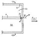
図1は流体流のサイズを小さくする、あるいは第二の流体によって分離された第一の流体の小滴を作製する一般的な先行技術の「フローフォーカシング」技法の部分的な概略断面図である。図1の構成では、管10は、管10が収容されている容器16の壁に造られた小さなオリフィス14の上流に配置されオリフィス14に方向を向けた出口12を有する。第一の流体18は管10の中を流れ、出口12で流体10から出る。第二の流体20はハウジング16の外部の圧力より高い圧力でハウジング16の内部22に閉じ込められている。この圧力差によって流体20はオリフィス14を通ってハウジング16から漏れ出し、流体18は流体20の作用によってオリフィス14の方向に引き伸ばされ、オリフィス14を通って引き出される。定常な流体18の細い液体ジェット24が生成し、不連続な部分に分割することができる。通常「フローフォーカシング」として知られているこの技法は燃料噴射、食品粒子製造、医薬品製造などを含むさまざまな用途で記載されている。 FIG. 1 is a partial schematic cross-sectional view of a typical prior art “flow focusing” technique that reduces the size of a fluid stream or creates droplets of a first fluid separated by a second fluid. . In the configuration of FIG. 1, the
図2は図1の線2−2での断面図であり、ハウジング16および管10を示す。ハウジング16は、流体18が管10の出口から出るときに流体20が流体18を完全に囲むよう、一般に管10を完全に囲むように構成される。図1および2の構成は複数の部品から製作され、一般に本発明の装置の構築に対して相対的に複雑な多段階の製造工程を必要とし、全体的な規模では一般にはるかに大きい。 FIG. 2 is a cross-sectional view taken along line 2-2 of FIG. The
次に図3を参照して、本発明の一つの実施形態の概略をミクロ流体素子システム26の形で断面図に例示する(図4の上部壁38がなければ、システム26の上面図は同じように見えると理解されるが)。本発明のシステムの特定の部分および全体を定義するために「上部」および「底部」が用いられるが、説明するものとは異なる向きでシステムを使用することもできることが理解される。参照の都合上、図3の向きで流体が最適には左から右に流れるようにシステムが設計されている点に注意する。 Referring now to FIG. 3, an outline of one embodiment of the present invention is illustrated in cross-section in the form of a microfluidic device system 26 (without the
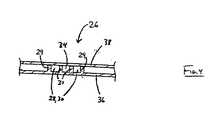
システム26はミクロ流体素子システムの領域の形状を定める一連の壁を含む。これらの壁によってシステムを説明する。ミクロ流体相互連結領域28はシステム内で壁29によって定められ、上流部分30、および図3に示していないもっと下流で出口に接続する下流部分32を含む。図3に例示する実施形態では、相互連結領域28の外部境界内に側壁31によって形状を定められる目的の流体チャンネル34が提供される。目的の流体チャンネル34は、相互連結領域28の上流部分30と下流部分32との間で出口37を有する。したがって、システムは上流部分と下流部分との間でチャンネル34から相互連結領域に目的の流体を送達するように構成されている。
図4は、図3の線4−4での断面図であり、壁29および31と共に連続領域28(その上流部分30で)および目的の流体チャンネル34の形状を定める底部壁36および上部壁38(図3に示す一部構成部品(壁29および31)の他に)を示す。相互連結領域28は、上流部分30では目的の流体チャンネル34によって分けられた二つの別個の部分を含むことが分かる。別個の部分はさらに下流で相互連結されている。 FIG. 4 is a cross-sectional view taken along line 4-4 of FIG. 3 and includes a
再び図3を参照して、相互連結領域28は側壁29から相互連結領域に伸びる延長部分42によって形成される寸法制限部分40を含む。例示した実施形態では、相互連結領域の上流部分30から下流部分32に流れる流体は寸法制限部分40の中を通過しなければならない。目的の流体チャンネル34の出口37は寸法制限部分の上流に配置される。例示した実施形態では、相互連結領域28の下流部分は中心軸44を有し、中心軸44は目的の流体チャンネル34の中心軸と同じである。すなわち、目的の流体チャンネルは寸法制限部分の上流で、寸法制限部分と同じ線上で目的の流体を放出するように配置されている。図3に示すように構成されると、目的の流体チャンネル34は相互連結領域28の内部の部分に目的の流体を放出する。すなわち、相互連結領域の外側の境界は目的の流体チャンネルの外側の境界の外側にある。相互連結領域中で下流に流れる流体が目的の流体チャンネルから放出される流体と合流する正確な地点で、目的の流体は相互連結領域内の流体によって少なくとも部分的に囲まれるが、相互連結領域内の流体によって完全には囲まれない。例示する実施形態では、代わりにほぼその外周の50%で囲まれる。目的の流体の外周の一部分は底壁36および上部壁38によって押さえられている。 Referring again to FIG. 3, the
例示する実施形態では、寸法制限部分は環状のオリフィスであるが、さまざまな形の任意の形状をとってよい。たとえば細長くても、卵形でも、正方形その他でもよい。好ましくは、分散流体に目的の流体の断面形状を囲ませて制限させる原因となるような任意の形状にされる。好ましい実施形態では、寸法制限部分は弁を使用しない。すなわち、それは開状態と閉状態との間で切り替えることができないオリフィスであり、一般に固定サイズである。 In the illustrated embodiment, the dimension limiting portion is an annular orifice, but may take any of a variety of shapes. For example, it may be elongated, oval, square or other. Preferably, the dispersion fluid has an arbitrary shape that causes the cross-sectional shape of the target fluid to be enclosed and limited. In a preferred embodiment, the dimension limiting portion does not use a valve. That is, it is an orifice that cannot be switched between an open state and a closed state, and is generally a fixed size.
図3および4には示さないが、目的の流体に対する分散流体の作用によって造り出された目的の流体の不連続な部分を囲む封入流体を提供するために、図3および4の構成中に一つ以上の中間流体チャンネルを提供してもよい。一つの実施形態では、目的の流体チャンネル34の両側に一つずつ、目的の流体チャンネルの出口の近くにそれぞれ出口を有する二つの中間流体チャンネルが提供されている。 Although not shown in FIGS. 3 and 4, in order to provide an encapsulating fluid that surrounds a discontinuous portion of the target fluid created by the action of the dispersion fluid on the target fluid, one may be included in the configuration of FIGS. More than one intermediate fluid channel may be provided. In one embodiment, two intermediate fluid channels are provided, one on each side of the
すべての実施形態ではないが、ある実施形態では、システム26の構成部品はすべてミクロ流体素子である。本明細書中で用いられる「ミクロ流体」とは、1ミリメートル(mm)未満の断面寸法および少なくとも3:1の長さ対最大断面寸法の比を有する少なくとも一つの流体チャンネルを含む素子、装置またはシステムを指し、「ミクロ流体チャンネル」はこれらの基準を満たすチャンネルである。断面寸法は流体流方向に対して垂直に測定される。本発明の構成部品内の大部分の流体チャンネルは2ミリメートル未満、好ましくは1ミリメートルの最大断面寸法を有する。ある一連の実施形態では、少なくとも、一つの流体が別の流体によって分散させられる領域では、流体チャンネルはすべてミクロ流体素子、または2ミリメートル以下の最大断面寸法である。別の実施形態では、単一構成部品(たとえばエッチング基板または成形ユニット)によって部分的に形成された、流体の分散に関連する流体チャンネルはすべてミクロ流体素子、または最大寸法2ミリメートルである。もちろん、これより大きなチャンネル、管などを用いて流体を大量に貯蔵し、本発明の構成部品に流体を送達してもよい。 In some, but not all embodiments, the components of
本明細書中で用いられる「ミクロ流体相互連結領域」とは、流体によって連絡する二つ以上のミクロ流体チャンネルを含む装置、装置またはシステムの一部分を指す。 As used herein, “microfluidic interconnect region” refers to a device, part of a device or system that includes two or more microfluidic channels that are in fluid communication.
ある一連の実施形態では、すべての能動流体チャンネル、すなわち流体の分散に関与するすべてのチャンネル、の最大断面寸法は、500ミクロンまたは200、100、50、または25ミクロン未満である。たとえば、相互連結領域28の断面50ならびに目的の流体チャンネル34の最大断面寸法52はこれらの寸法のどれよりも小さくてもよい。相互連結領域28の上流部分30はこれらの最大断面境界値のどれによって定められてもよい。装置およびシステムはミクロ流体素子的でない部分も有するチャンネルを含むことがある。 In one set of embodiments, the maximum cross-sectional dimension of all active fluid channels, i.e. all channels involved in fluid dispersion, is less than 500 microns or 200, 100, 50, or 25 microns. For example, the cross-section 50 of the
本明細書中で用いられる「チャンネル」とは、少なくとも部分的に流体流を誘導する物品(基板)の上部または内部の微細構造を意味する。微細構造は任意の断面形状(図に例示するように曲線、正方形または長方形など)の溝であってよく、被覆されていてもいなくてもよい。微細構造が完全に被覆されている実施形態では、チャンネルの少なくとも一部分が完全に囲まれた断面を有することがあり、あるいはチャンネル全体がその入口と出口とを除いて全長にわたって完全に囲まれていることがある。特に明記しない限り、添付する図に例示する実施形態では、チャンネルはすべて完全に囲まれている。 As used herein, “channel” means a microstructure on or within an article (substrate) that at least partially induces fluid flow. The microstructure may be a groove of any cross-sectional shape (such as a curve, square or rectangle as illustrated in the figure) and may or may not be covered. In embodiments where the microstructure is completely covered, at least a portion of the channel may have a completely enclosed cross section, or the entire channel may be completely enclosed over its entire length except for its inlet and outlet. Sometimes. Unless otherwise stated, in the embodiment illustrated in the accompanying figures, all channels are completely enclosed.
本発明の一つの局面はミクロ流体素子流体結合システムの単純化された製造方法、およびそれによる一般的な先行技術のシステムより少ない構成部品で定められるシステムを含む。たとえば、図3および4に例示する構成では、底壁36および壁29および31は互いに一体化されている。本明細書中で用いられる「一体化されている」とは、構成部品を互いに切断または破壊することなしには互いに分けられないように部分が結合していることを意味する。例示するように、底壁36ならびに壁31および29は物質の一個の品物から作製される。例示する実施形態では、相互連結領域28および目的の流体チャンネル34の上部壁を定める上部38は底壁36ならびに壁31および29と同じ物質で作製してもよいし、あるいは異なる物質で作製してもよい。一つの実施形態では、上記で説明した構成部品の少なくとも一部は、流体流を観測できるように透明である。たとえば、上部壁38はガラスのような透明物質であってもよい。 One aspect of the present invention includes a simplified method of manufacturing a microfluidic fluid coupling system and thereby a system defined with fewer components than a typical prior art system. For example, in the configuration illustrated in FIGS. 3 and 4, the
さまざまな物質および方法を用いてシステム26の構成部品を作製してもよい。ある場合には、選択したさまざまな物質がさまざまな方法で使用される。たとえば、固体物質から本発明の構成部品を作製してもよく、その場合にはミクロ機械加工、スピンコーティングおよび化学蒸着法などの膜作製方法、レーザー加工法、フォトリソグラフィー法、湿式化学物質またはプラズマプロセスを含むエッチング法などによってチャンネルを作製してもよい。たとえば、サイエンティフィックアメリカン(Scientific American)248巻44〜55頁(1983年)のエンジェル(Angell)らを参照すること。一つの実施形態では、システムの少なくとも一部(たとえば底壁36ならびに壁29および31)は、シリコンチップに微細構造をエッチングすることによってケイ素で作製される。ケイ素から本発明の装置を製造する精密で効率的な技術は既知である。別の実施形態では、部分(またはその他の部分)はポリマーで作製してもよく、エラストマーまたはポリテトラフルオロエチレン(PTFE,テフロン(登録商標))などでもよい。 Various materials and methods may be used to make the components of
種々の物質で種々の構成部品を製作することができる。たとえば、底壁36ならびに側壁29および34を含むベース部分はケイ素またはPDMSなどの不透明物質で製作してもよく、上部38は流体プロセスの観測および制御のためにガラスまたは透明なポリマーなどの透明物質で製作してもよい。ベース支持体物質がちょうど所望の官能基を有しない場合には、構成部品に塗布して内部チャンネル壁と接触する流体に所望の化学官能基を露出させてもよい。たとえば、例示するように内部チャンネル壁を別の物質で塗布して構成部品を製作してもよい。 Different components can be made with different materials. For example, the base portion including the
本発明の装置を製作するために用いられる物質、あるいは流体チャンネル内壁を被覆するために用いられる物質は、好ましくは装置内を流れる流体に悪影響を与えない、あるいは装置内を流れる流体によって悪影響を受けない物質、たとえば、装置内で用いられる作業温度および圧力で流体の存在下で化学的に不活性である物質(単数または複数)の中から選ばれ得る。 The material used to fabricate the device of the present invention, or the material used to coat the inner walls of the fluid channel, preferably does not adversely affect the fluid flowing in the device or is adversely affected by the fluid flowing in the device. There may be selected from non-substances, for example, one or more substances that are chemically inert in the presence of fluid at the working temperature and pressure used in the apparatus.
一つの実施形態では、本発明の構成部品は重合体および/または可撓性および/またはエラストマー物質で製作され、好都合には、硬化性流体で成形(たとえばレプリカ成形、射出成形、注型成形など)による製造を容易にして作製してもよい。硬化性流体は基本的に、ミクロ流体網目構造中およびミクロ流体網目構造との用途で考えられる流体を収容および輸送できる固体中への固体化を誘起すること、あるいは自発的に固まることができる任意の流体形であってもよい。一つの実施形態では、硬化性流体は重合体液体または液状の重合体前駆物質(すなわち「プレポリマー」)を含む。適当な重合体液体はたとえば熱可塑性ポリマー、熱硬化性ポリマー、または融点より高温に熱されたそのようなポリマーの混合物、あるいは溶媒の除去、たとえば蒸発によって溶液が固体重合物質を形成する適当な溶媒中の一つ以上のポリマーの溶液を含んでもよい。たとえば、溶融状態から、溶媒蒸発によって、または触媒反応によって固化できるような重合体物質は当業者には周知である。さまざまな重合物質(このうちの多数はエラストマーである)が適当であり、また鋳型マスターの一方または両方がエラストマー物質で構成される実施形態については、二次鋳型または鋳型マスターにも適当である。そのようなポリマーの非限定的な例のリストはシリコーンポリマー、エポキシポリマーおよびアクリレートポリマーの一般的な種類のポリマーを含む。エポキシポリマーは一般にエポキシ基、1,2−エポキシド、またはオキシランと呼ばれる三員環の環状エーテル基の存在によって特徴づけられる。たとえば、芳香族アミン、トリアジン、および脂環式骨格にもとづく化合物に加えて、ビスフェノールAのジグリシジルエーテルを用いてもよい。別の例は、周知のノボラックTM(NovolacTM)ポリマーを含む。本発明による用途に適するシリコーンエラストマーの例はメチルクロロシラン、エチルクロロシランおよびフェニルクロロシランなどのようなクロロシラン類を含む前駆物質から形成されるものを含む。In one embodiment, the components of the present invention are made of a polymer and / or flexible and / or elastomeric material, conveniently molded with a curable fluid (eg, replica molding, injection molding, cast molding, etc.) ) May be produced with ease. A curable fluid is basically any that can induce solidification into a solid that can contain and transport fluids in and with microfluidic networks, or that can spontaneously solidify It may be a fluid type. In one embodiment, the curable fluid comprises a polymer liquid or a liquid polymer precursor (ie, “prepolymer”). Suitable polymer liquids are, for example, thermoplastic polymers, thermosetting polymers, or mixtures of such polymers heated above the melting point, or suitable solvents in which the solution forms a solid polymer by removal of the solvent, for example evaporation. A solution of one or more polymers therein may be included. For example, polymeric materials that can be solidified from a molten state, by solvent evaporation, or by catalytic reaction are well known to those skilled in the art. Various polymeric materials (many of which are elastomers) are suitable, and for embodiments in which one or both of the mold masters is composed of an elastomeric material, it is also suitable for a secondary mold or mold master. A list of non-limiting examples of such polymers includes the general types of polymers: silicone polymers, epoxy polymers and acrylate polymers. Epoxy polymers are generally characterized by the presence of a three-membered cyclic ether group called an epoxy group, 1,2-epoxide, or oxirane. For example, diglycidyl ether of bisphenol A may be used in addition to compounds based on aromatic amines, triazines, and alicyclic skeletons. Another example includes the well-known novolacTM (NovolacTM) polymers. Examples of silicone elastomers suitable for use with the present invention include those formed from precursors containing chlorosilanes such as methylchlorosilane, ethylchlorosilane, phenylchlorosilane, and the like.
ある一連の実施形態ではシリコーンポリマー、たとえばシリコーンエラストマーポリジメチルシロキサン(PDMS)が好ましい。ポリジメチルシロキサンポリマーの例には、ミシガン州ミッドランドのダウケミカル社(Dow Chemical Co.,Midland,MI)によってシルガード(登録商標)(Sylgard(登録商標))、詳しくはシルガード182、シルガード184、およびシルガード186の商標名で販売されているものが含まれる。PDMSを含むシリコーンポリマーは本発明のミクロ流体構造体の製造を単純化するいくつかの有益な性質を有する。第一に、そのような物質は安価であり、容易に入手でき、熱で硬化することによってプレポリマー液から固体化することができる。たとえば、一般にPDMSは、たとえば約1時間の加熱時間の間、たとえば約65℃から約75℃の温度にプレポリマー液をさらすことによって硬化できる。第二に、PDMSなどのシリコーンポリマーはエラストマーであり、したがって本発明のある種の実施形態で必要な比較的アスペクト比の高い非常に小さな微細構造を形成するために有用である。柔軟な(たとえばエラストマー)鋳型またはマスターはこの点に関しては好都合であり得る。 In one set of embodiments, silicone polymers, such as silicone elastomer polydimethylsiloxane (PDMS), are preferred. Examples of polydimethylsiloxane polymers include Sylgard® (Sylgard®) by Dow Chemical Co., Midland, MI, specifically Sylgard 182, Sylgard 184, and Sylgard. Those sold under the trade name of 186 are included. Silicone polymers including PDMS have several beneficial properties that simplify the manufacture of the microfluidic structures of the present invention. First, such materials are inexpensive, readily available, and can be solidified from prepolymer liquids by curing with heat. For example, generally PDMS can be cured by exposing the prepolymer liquid to a temperature of, for example, about 65 ° C. to about 75 ° C., for example, for a heating time of about 1 hour. Second, silicone polymers such as PDMS are elastomers and are therefore useful for forming very small microstructures with relatively high aspect ratios required in certain embodiments of the invention. A flexible (eg elastomeric) mold or master may be advantageous in this regard.
PDMSなどのシリコーンポリマーから本発明のミクロ流体構造体を作製することの別の利点は、たとえば空気プラズマなどの酸素含有プラズマにさらすことによって酸化されるそのようなポリマーの能力である。その結果、酸化された構造体は、他の酸化されたシリコーンポリマー表面またはさまざまなその他の重合体および非重合体物質の酸化された表面に架橋できる化学基を表面に含む。したがって、構成部品が製作され得、次いで酸化され得、別個の接着剤またはその他の封着手段を必要とすることなく、他のシリコーンポリマー表面、または酸化されたシリコーンポリマー表面と反応する、その他の基板の表面に本質的に不可逆的に封着される。ほとんどの場合、酸化されたシリコーン表面を別の表面に単に接触させることによって、封着を形成するために補助的な圧力を加える必要もなく、封着を完了することができる。すなわち、あらかじめ酸化されたシリコーン表面は、適当な合わせ面に対してコンタクト型接着剤として作用する。特に、自身に不可逆的に封着可能であることに加えて、酸化されたPDMSなどの酸化されたシリコーンはさらに、たとえばPDMS表面と同じように(たとえば酸素含有プラズマに接触させることにより)酸化されたガラス、ケイ素、酸化ケイ素、石英、窒化ケイ素、ポリエチレン、ポリスチレン、ガラス状炭素およびエポキシポリマーを含む、自身を除く広い範囲の酸化された物質に不可逆的に封着することができる。本発明の分野に関連する有用な酸化および封着方法ならびに全体的な成形技術は、参考として本明細書中に援用されるアナリティカル・ケミストリー(Analytical Chemistry)第70巻474〜480頁(1998年)のダフィー(Duffy)らの「ミクロ流体素子システムおよびポリジメチルシロキサンの迅速なプロトタイプ作製(Rapid Prototyping of Microfluidic Systems and Polydimethylsiloxane)」中で説明されている。 Another advantage of making the microfluidic structures of the present invention from silicone polymers such as PDMS is the ability of such polymers to be oxidized by exposure to an oxygen-containing plasma such as an air plasma. As a result, the oxidized structure includes chemical groups on the surface that can crosslink to other oxidized silicone polymer surfaces or the oxidized surfaces of various other polymeric and non-polymeric materials. Thus, a component can be fabricated and then oxidized and reacted with other silicone polymer surfaces or oxidized silicone polymer surfaces without the need for a separate adhesive or other sealing means It is essentially irreversibly sealed to the surface of the substrate. In most cases, the sealing can be completed by simply contacting the oxidized silicone surface with another surface without the need to apply additional pressure to form the seal. That is, the pre-oxidized silicone surface acts as a contact adhesive for a suitable mating surface. In particular, in addition to being irreversibly sealable to itself, oxidized silicones such as oxidized PDMS are further oxidized, for example, in the same way as PDMS surfaces (eg by contact with an oxygen-containing plasma). It can be irreversibly sealed to a wide range of oxidized materials except itself including glass, silicon, silicon oxide, quartz, silicon nitride, polyethylene, polystyrene, glassy carbon and epoxy polymers. Useful oxidation and sealing methods and overall molding techniques related to the field of the invention are described in Analytical Chemistry 70: 474-480 (1998), which is incorporated herein by reference. Duffy et al., “Rapid Prototyping of Microfluidic Systems and Polydimethylsiloxane”.
酸化されたシリコーンポリマーから本発明のミクロ流体素子構造(または内部の流体接触表面)を作製することの別の利点は、これらの表面が一般的なエラストマーポリマーの表面よりずっと親水性になり得ること(親水性の内部表面が望ましい場合)である。そのような親水性のチャンネル表面は、したがって一般的な酸化されていないエラストマーまたはその他の疎水性物質で構成された構造体よりも、より簡単に水溶液で満たし濡らすことができる。したがって、酸化されていないエラストマーポリマーよりも親水性の大きい表面を有する本発明の素子を製作することができる。 Another advantage of making the microfluidic device structures (or internal fluid contact surfaces) of the present invention from oxidized silicone polymers is that these surfaces can be much more hydrophilic than typical elastomeric polymer surfaces. (When a hydrophilic internal surface is desired). Such hydrophilic channel surfaces can therefore be more easily filled and wetted with aqueous solutions than structures composed of common non-oxidized elastomers or other hydrophobic materials. Thus, it is possible to fabricate the device of the present invention having a surface that is more hydrophilic than the unoxidized elastomeric polymer.
一つの実施形態では、底壁36は壁29または31の一つ以上、あるいは上部壁38またはその他の構成部品とは異なる物質で作製される。たとえば、底壁36の内部表面はシリコンウエハまたはマイクロチップの表面あるいはその他の基板を含んでもよい。上記で説明したように、その他の構成要素はそのような代替基板に封着することができる。シリコーンポリマー(たとえばPDMS)を含む構成部品を異なる物質の基板(底部)に封着することが望まれる場合には、酸化されたシリコーンポリマーが不可逆的に封着することができる物質の群から基板を選ぶことが好ましい(たとえば酸化されたガラス、ケイ素、酸化ケイ素、石英、窒化ケイ素、ポリエチレン、ポリスチレン、エポキシポリマー、およびガラス状炭素表面)。あるいは、当業者にとって明らかである個別の接着剤、熱結合、溶剤結合、超音波溶接などの使用を含むが、これらに限定されないその他の封着技法を用いてもよい。 In one embodiment, the
本発明は、分散流体中の不連続なまたは孤立した目的の流体の領域の生成を提供するが、オプションとして目的の流体は一つ以上の中間流体によって隔てられていることがある。中間流体は流体間の関係を考慮することによって、当業者によって基本的に任意の流体(液体、気体など)の間で選ばれ得る。たとえば、目的の流体および分散流体は、分散した部分の生成の時間枠内では混ざらないように選ばれる。分散した部分がかなりの時間の間液体のままの場合には、流体は著しく混ざらないものである方がよい。分散した部分の生成の後で、分散した部分が重合などによって迅速に硬化する場合、流体は非混合性である必要はない。当業者は本発明の技法を実行するために接触角測定などを用いて適当な非混合流体を選ぶことができる。 The present invention provides for the generation of discrete or isolated regions of the target fluid in the dispersed fluid, but optionally the target fluid may be separated by one or more intermediate fluids. The intermediate fluid can be chosen between essentially any fluid (liquid, gas, etc.) by those skilled in the art by considering the relationship between the fluids. For example, the target fluid and the dispersion fluid are selected so that they do not mix within the time frame for generating the dispersed portion. If the dispersed portion remains liquid for a significant amount of time, the fluid should not mix significantly. The fluid need not be immiscible if the dispersed portion cures rapidly, such as by polymerization, after formation of the dispersed portion. One skilled in the art can select a suitable unmixed fluid using contact angle measurements or the like to perform the techniques of the present invention.
本明細書中の教示(ならびにフローフォーカシングの分野で利用可能な教示)にもとづいて、目的の流体の分散は当業者によって制御され得る。本発明の目的を実行する流体の選択のためには、たとえば1998年1月12日のフィジカル・レビューズ・レターズ80巻2号のガナン−カルボの「安定な液体微小流およびミクロンサイズの単分散スプレーおよびガス流体の生成」ならびに多数のその他の文献を参照することができる。下記の例からさらに完全に理解されるように、分散流体の流速の制御および分散流体と目的の流体との間の流速比を用いて、目的の流体流および/または分散サイズおよび分散液中の単分散度対多分散度を制御することができる。本発明のミクロ流体素子は、本明細書中に教示するように流速および比率の制御と結びついて、著しく改良された制御および範囲を可能にする。分散部分のサイズは直径一ミクロン未満にまで小さくすることができる。 Based on the teachings herein (as well as the teachings available in the field of flow focusing), the distribution of the target fluid can be controlled by those skilled in the art. For the selection of fluids that carry out the objectives of the present invention, see “Stable liquid microfluids and micron-sized monodispersions, eg, Gannan-Carbo, Physical Reviews Letters, Vol. 80, No. 2, Jan. 12, 1998. Reference can be made to "spray and gas fluid generation" and a number of other references. As will be more fully understood from the examples below, control of the flow rate of the dispersed fluid and the flow rate ratio between the dispersed fluid and the target fluid can be used to achieve the desired fluid flow and / or dispersion size and in the dispersion. Monodispersity versus polydispersity can be controlled. The microfluidic device of the present invention allows for significantly improved control and range in conjunction with flow rate and ratio control as taught herein. The size of the dispersed portion can be reduced to less than 1 micron in diameter.
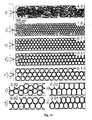
多くの分散はバルクの性質(たとえばレオロジー、分散(単数または複数)がどのように流れるか、およびオプションとして光学的性質、味、触感など分散粒子の大きさおよび分散粒子の粒度分布によって影響されるその他の特質を有する。一般的な先行技術技法、たとえば先行技術のフローフォーカシング技法は最も一般的に単分散系を含む。本発明はまた不連続な部分の分布結果を複分散および多分散させる条件の制御を含む。これは不連続な粒度分布などを変更することによってバルクの性質に影響を及ぼすとき有用であり得る。 Many dispersions are affected by the bulk properties (eg rheology, how the dispersion (s) flow, and optionally the optical properties, taste, feel etc. of the dispersed particles and the size distribution of the dispersed particles General prior art techniques, such as prior art flow focusing techniques, most commonly include monodisperse systems, and the present invention also provides conditions for disperse and polydisperse discontinuous distribution results. This can be useful when affecting the properties of the bulk, such as by changing the discontinuous particle size distribution.
本発明を用いて医療(たとえば医薬品)、スキンケア製品(たとえばローション、シャワーゲル)、食品(たとえばサラダドレッシング、アイスクリーム)、インクのカプセル化、塗料、マイクロエンジニアリング材料(たとえばフォトニック結晶、スマート材料など)のマイクロテンプレート化、泡などで使用するためのさまざまな分散した流体の部分または粒子を作製することができる。本発明によって製造された高度に単分散の濃縮された液晶小滴は二次元および三次元構造へ自己組織化することができ、これらはたとえば新規な光学装置中に使われ得る。 Medical (eg pharmaceuticals), skin care products (eg lotions, shower gels), foods (eg salad dressings, ice creams), ink encapsulations, paints, microengineering materials (eg photonic crystals, smart materials etc.) using the present invention ) Can be made into a variety of dispersed fluid parts or particles for use in microtemplates, foams, and the like. The highly monodispersed concentrated liquid crystal droplets produced according to the present invention can self-assemble into two-dimensional and three-dimensional structures, which can be used, for example, in novel optical devices.
本発明の一つの特長は目的の流体の不連続な部分の大きさに対する強められた制御である。これは多くの先行技術の技法と対照的である。一般に、先行技術では内部流体は流体が強制的に通らされるオリフィスより小さいサイズの流れまたは滴の集合中に引き込まれる。本発明では、ある実施形態には寸法制限部分の平均断面寸法以上の平均断面寸法または平均直径をそれぞれ有する目的の流体流および/または不連続な部分の作製が含まれる。本発明には、代わりにミクロ流体素子環境による分散流体、目的の流体のどちらかまたは両方の流速の制御および/またはこれらの流速の比の制御によるこれらの平均断面寸法または直径に対する制御が含まれる。他の実施形態では、目的の流体の流れおよび/または不連続な部分は寸法制限部分の平均断面寸法のそれぞれ90%以上の平均断面寸法または平均直径を有し、あるいはその他の実施形態では寸法制限部分の平均断面寸法の80%、70%、60%、50%、40%または30%以上の平均断面寸法または平均直径を有する。これは、本発明のシステムが広い流速の範囲にわたって機能し得、しきい値流速の点までは、変化する流速の下で基本的に同じ流れのサイズまたは不連続な部分のサイズを製造する(サイズはたとえば寸法制限部分の寸法によって定まる)ことができる点で有利であり得る。しきい値流速では、流速を増大すると対応する減少が目的の流体流および/または不連続な部分の平均断面寸法または平均直径にそれぞれ起きる。 One feature of the present invention is enhanced control over the size of the discontinuous portion of the target fluid. This is in contrast to many prior art techniques. In general, in the prior art, internal fluid is drawn into a stream or drop collection of smaller size than the orifice through which the fluid is forced. In the present invention, certain embodiments include the creation of a target fluid flow and / or a discontinuous portion each having an average cross-sectional dimension or average diameter that is greater than or equal to the average cross-sectional dimension of the dimensionally limited portion. The present invention includes control over these mean cross-sectional dimensions or diameters by controlling the flow rate of the dispersed fluid, the fluid of interest, or both, and / or the ratio of these flow rates, instead by the microfluidic device environment. . In other embodiments, the target fluid flow and / or discontinuous portion has an average cross-sectional dimension or average diameter that is 90% or more of the average cross-sectional dimension of the dimensionally limited portion, respectively, or in other embodiments, the size-limited It has an average cross-sectional dimension or average diameter of 80%, 70%, 60%, 50%, 40% or 30% or more of the average cross-sectional dimension of the part. This allows the system of the present invention to function over a wide range of flow rates, producing up to essentially the same flow size or discontinuous size under varying flow rates up to the threshold flow rate point ( It can be advantageous in that the size can be determined, for example, by the dimensions of the dimension limiting portion. At the threshold flow rate, increasing the flow rate causes a corresponding decrease in the target fluid flow and / or the average cross-sectional dimension or average diameter of the discontinuous portion, respectively.
ある実施形態では、気−液分散を用いて泡を製造することがある。気−液分散中の気体の体積パーセントが増大するにつれて、個々の気泡は互いに押し付けられ球状の形状を失うことがある。一つ以上の表面によって制約されると、これらの球体は円盤形に圧縮されることがあるが、一般に圧縮する面から見ると円形の形状パターンを維持する。一般に、より高い体積パーセントで気泡が非球体または多面体になると分散は泡と呼ばれる。泡が形成されるときには多くの因子、たとえば分散サイズ、粘度、および表面張力が影響を及ぼすことがあるが、ある実施形態では、気−液分散中の気体の体積パーセントがたとえば75、80、85、90または95を超えると泡(非球体の気泡)が生成する。 In some embodiments, gas-liquid dispersion may be used to produce the foam. As the volume percent of gas in the gas-liquid dispersion increases, the individual bubbles can be pressed together and lose their spherical shape. When constrained by one or more surfaces, these spheres may be compressed into a disk shape, but generally maintain a circular shape pattern when viewed from the compressing surface. In general, dispersion is referred to as bubbles when the bubbles become non-spherical or polyhedral at higher volume percentages. Although many factors can affect when bubbles are formed, such as dispersion size, viscosity, and surface tension, in certain embodiments, the volume percent of gas in the gas-liquid dispersion is, for example, 75, 80, 85 , 90 or 95, bubbles (non-spherical bubbles) are generated.
本発明のある局面によってより小さな小滴に分割され得る始めの目的の流体小滴(または分散相)の生成について説明する。基本的に本明細書中で説明するものを含む任意の技法が目的の流体小滴を作製するために使用できることが理解される。目的の流体小滴を作製する一つの技法は、図1に示すもののような装置を用いて実施できる。図1は流体流の大きさを減少させ、あるいは第二の流体によって分けられた第一の流体の小滴を作製する一般的な先行技術の「フローフォーカシング」技法の部分的な断面概略図である。構成は上記で説明した。 The production of an initial target fluid droplet (or dispersed phase) that can be divided into smaller droplets according to one aspect of the present invention is described. It will be appreciated that essentially any technique, including those described herein, can be used to make a fluid droplet of interest. One technique for producing a target fluid droplet can be performed using an apparatus such as that shown in FIG. FIG. 1 is a partial cross-sectional schematic diagram of a common prior art “flow focusing” technique that reduces the size of a fluid flow or creates a first fluid droplet separated by a second fluid. is there. The configuration has been described above.
目的の流体小滴作製のための別の技法は、本明細書中で説明した図3の装置を使用することによる。図3は断面概略図で例示したミクロ流体素子システム26を示す(上部壁がなければシステム26の上面図は同じように見えると理解されるが)。本発明のシステムの特定の部分および全体を定義するために「上部」および「底部」が用いられるが、説明するものとは異なる方向でシステムを使用してもよいことが理解されるべきである。参照の都合上、図3の方向で流体が最適には左から右に流れるようにシステムが設計されている点に注意する。システム26はミクロ流体素子システムの部分の形状を定める一連の壁を含む。これらの壁を用いてシステムを説明する。ミクロ流体相互連結部分28はシステム内で壁29によって定められ、上流部分30および下流部分32を含む。下流部分32は図3には示していないもっと下流で出口に連結する。図3に例示する実施形態では、相互連結領域28の外部境界の内側に側壁31によって定められた目的の流体チャンネル34が提供される。目的の流体チャンネル34は、相互連結領域28の上流部分と下流部分との間に出口37を有する。したがって、システムはチャンネル34から上流部分と下流部分との間の相互連結領域に目的の流体を送達するように構成されている。相互連結領域28は側壁29から相互連結領域に伸びる延長部分42によって形成される寸法制限部分40を含む。例示した実施形態では、相互連結領域の上流部分30から下流部分32に流れる流体は寸法制限部分40の中を通過しなければならない。目的の流体チャンネル34の出口37は寸法制限部分の上流に配置される。例示した実施形態では、相互連結領域28の下流部分は中心軸44を有し、中心軸44は目的の流体チャンネル34の中心軸と同じである。すなわち、目的の流体チャンネルは寸法制限部分の上流で、寸法制限部分と同じ線上に目的の流体を放出するように配置されている。図3に示すように構成されると、目的の流体チャンネル34は相互連結領域28の内部の部分に目的の流体を放出する。すなわち、相互連結領域の外側の境界は目的の流体チャンネルの外側の境界の外側にある。相互連結領域を通って下流に流れる流体が目的の流体チャンネルから放出される流体と合流する正確な地点で、目的の流体は少なくとも部分的に相互連結領域内の流体によって囲まれるが、相互連結領域の流体によって完全には囲まれない。例示する実施形態では、代わりにその外周のほぼ50%で囲まれる。 Another technique for producing targeted fluid droplets is by using the apparatus of FIG. 3 described herein. FIG. 3 shows the
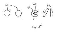
次に図5を参照して、本発明の小滴作製のための一つの一般原理の概略を図示する。図5では、複数の目的の小滴60が矢印62によって示される方向に流れる。小滴60は分散媒(小滴60を囲んでいるが図には特に示していない)中に閉じ込められた分散相小滴である。小滴60は障害物62に向かって流れ、衝突させられ、小滴60はそれによって障害物の下流でさらに小さな小滴64に分割される。本明細書中で説明したミクロ流体素子技法を含む任意の適当な技法を用いて、小滴60を障害物62に誘導し得、障害物62に衝突させ得、これによって小滴64に分割し得る。 Referring now to FIG. 5, a schematic of one general principle for making droplets of the present invention is illustrated. In FIG. 5,
ある一連の実施形態では、目的の流体小滴は、5ミリメートル、または1ミリメートル、500ミクロン、250ミクロン、100ミクロン、60ミクロン、40ミクロン、20ミクロン、または10ミクロン以下の最大断面寸法を有する。小滴が実質的に球形の場合には、最大断面寸法は球体の直径である。作製されたさらに分散した小滴64は上記に列挙したばかりのものと同じ最大断面寸法を有してもよいが、もちろん最大断面寸法は小滴60より小さい。一般に、さらに分散した小滴64の最大断面寸法は最初の目的の小滴60の最大断面寸法の80%以下、または60%以下、40%、または小滴60の最大断面寸法の20%以下である。 In one set of embodiments, the target fluid droplet has a maximum cross-sectional dimension of 5 millimeters, or 1 millimeter, 500 microns, 250 microns, 100 microns, 60 microns, 40 microns, 20 microns, or 10 microns or less. If the droplet is substantially spherical, the maximum cross-sectional dimension is the diameter of the sphere. The further dispersed droplets 64 produced may have the same maximum cross-sectional dimensions as those just listed above, but of course the maximum cross-sectional dimension is smaller than the
図6を参照して、さまざまなサイズの小滴の作製(滴のサイズ分布または範囲の制御)のための一つの構成を例示する。図6では、複数のミクロ流体素子チャンネル66、68、70、72および74がそれぞれ複数の目的の小滴60(簡単化のためそれぞれの場合を一つの小滴で表す)を運び、小滴を囲む分散媒中で矢印76の方向に流れるように小滴を圧迫する。チャンネル66〜74はそれぞれ異なる配置の障害物を含む。チャンネル66には障害物がなく、小滴60は下流に流れるとき影響を受けない。チャンネル68は図5の配置を表わし、障害物62の下流で基本的に均一なサイズの小滴64が生成する。チャンネル70は直列に配置された複数の障害物を含み、チャンネル70のほぼ中央に一つ、第一の障害物の下流に残りの二つを第一の障害物とチャンネルの壁との間のほぼ中間地点にそれぞれ置いた。その結果は基本的に小滴64より小さい均一なサイズの複数の小滴76であり得る。チャンネル72は一つの障害物を含むが、中心から外れている。その結果、障害物の下流で滴のサイズが異なる少なくとも二つの異なる滴78と80が生成し得る。チャンネル74はチャンネルを横断する複数の等間隔の障害物を含み、その下流で基本的に均一な小さな液滴82の分布を生じ得る。チャンネル66〜74はそれぞれ、種々のサイズまたはサイズ分布の分散した小滴の集合を個別に作製するための個別のシステムを表すことができる。あるいは、これらのまたはその他のチャンネルの一部またはすべての出口を組み合わせて、基本的に任意の組合せの小滴サイズを有する任意の製品を生み出し得ることが基本的に可能である。 With reference to FIG. 6, one configuration for the production of droplets of various sizes (control of droplet size distribution or range) is illustrated. In FIG. 6, a plurality of
図6の構成は極めて図式的であり、本発明によって創出できる分散の多様性を表すことだけを意図している。障害物の下流での小滴の特定の分布は分散媒中の分散相の非混合性(非相容性)(流体の接触角の測定または当分野で既知のその他の性質における差異によって特徴づけられることがある)、流速、障害物サイズおよび形状などのような因子によって変化することが理解されるべきである。図5では三角形の断面形状の障害物が例示され、図6では実質的に円形の断面形状の障害物として高度に図式的に再現されているが、基本的に任意のサイズおよび断面形状(たとえば正方形、長方形、三角形、楕円形、円形)の障害物でも使うことができることが理解される。当業者は基本的に任意の分散媒サイズおよび分布結果を実現するために障害物のサイズ、形状および配置を選ぶことができる。チャンネルの形状およびサイズもさまざまなもの、たとえば上記で図3に関して説明したものから選ぶこともできる。 The configuration of FIG. 6 is very schematic and is intended only to represent the diversity of dispersions that can be created by the present invention. The specific distribution of the droplets downstream of the obstacle is characterized by differences in the dispersibility of the dispersed phase in the dispersion medium (measurement of the contact angle of the fluid or other properties known in the art) It should be understood that it will vary with factors such as flow rate, obstacle size and shape. FIG. 5 illustrates an obstacle with a triangular cross-sectional shape, and FIG. 6 is highly graphically reproduced as an obstacle with a substantially circular cross-sectional shape, but essentially any size and cross-sectional shape (eg, It is understood that obstacles of square, rectangle, triangle, ellipse and circle can also be used. A person skilled in the art can basically choose the size, shape and arrangement of the obstacles in order to achieve any dispersion medium size and distribution result. The channel shape and size can also be selected from a variety of, such as those described above with respect to FIG.
次に図7を参照して、ミクロ流体システム90の概略を例示し、分散相の小滴60を作製し、本発明によって障害物(単数または複数)を用いてこれをさらに分散させ得る一つの技法を示す。システム90は第一のチャンネル92、および垂直に配置され、チャンネル92との「T」字接合部で終わる第二のチャンネル94を含む。分散媒はチャンネル92の中をT字接合部の上流で矢印96の方向に流れ、分散相はチャンネル94の中をT字接合部の上流で矢印98の方向に流れる。流体小滴96として表される、チャンネル94を経て送達される流体の、チャンネル92を経て送達される分散媒中の分散相が、T字接合部で作製される。例示するT字接合部での分散媒中の分散相の作製は当分野では既知である。流体チャンネル中の分散媒および分散相の相対圧力、流速、その他の選択はすべて当業者によって慣用的に選ばれ得る。本発明によって、障害物98(中央に置かれた四角い断面の障害物として図7に表す)によって障害物の下流で小滴96がより小さな小滴100に分割されるようにした。各側壁からの相対距離(a)および(b)で示される障害物98の横の配置によって、上記で図6に関して参照したように、生じる分散相のサイズおよびサイズ分布の範囲の制御が可能になる。チャンネル92および94は基本的に任意の幾何学的な形状をとることができる。例示した実施形態では、それらは基本的に約1ミリメートル未満の側壁間の距離を表す寸法(c)または上記でチャンネルについて述べたその他の寸法を有する四角い横断面であることを意図する。 Referring now to FIG. 7, a schematic of a
代わりの構成では、図7に示すようにT字接合部で小滴96によって表される分散相を作製するのではなく、一つ以上の障害物の上流で図3に例示した配置を用いてもよい。 In an alternative configuration, instead of creating a dispersed phase represented by
障害物は基本的に任意のサイズおよび断面形状でよい。障害物は望ましくはさらに分散した相に分割される分散相を保持するチャンネル内の任意の場所に配置してよい。製造の容易さを目的として、一般にチャンネルの底面からその上面(図5、6および7ではチャンネル中で「下を」見ているとして)まで障害物をつなぎ、一般にこの間で均一な断面幾何学形状を有する。 Obstacles may basically be of any size and cross-sectional shape. The obstacle may be placed anywhere in the channel that holds the dispersed phase, which is desirably further divided into dispersed phases. For ease of manufacture, obstacles are typically connected from the bottom surface of the channel to its top surface (assuming that it is “looking down” in the channel in FIGS. 5, 6 and 7), and generally a uniform cross-sectional geometry between them Have
次に図8を参照して、分散相をさらに分散させるシステム110の概略を例示する。システム110では、入口チャンネル112が矢印114の方向でT字接合部116に流れる流体を送達し、T字接合部116でチャンネル112はそれぞれT字接合部から反対の方向に伸びる部分118および120を含む背圧制御チャンネルに垂直に接する。チャンネル118および120はそれぞれ集合チャンネル122および124に送達し、集合チャンネル118および120は最終的には合流して出口チャンネル126に流体を送達する。 Next, referring to FIG. 8, an outline of a system 110 for further dispersing the dispersed phase is illustrated. In system 110,
チャンネル112は任意の都合のよい方法(本明細書中で図1および3を参照して説明したもののような)および条件(当業者に知られているように分散相の大きさ、流速、圧力など)で作製した分散媒流体相内の分散流体相を矢印114の方向に送達して、T字路116で分散相を分割させる。本発明によってチャンネル118および120のそれぞれの中の相対的な流れ抵抗がこれらのチャンネル中を流れる分散相小滴(チャンネル118によって送達される相対的に小さな小滴128およびチャンネル120によって送達される相対的に大きな小滴130として表される)の相対的なサイズ(体積)を決定することがわかった。これらの小滴は送達チャンネル126中で一緒になる。他の点では対称形の装置中では、逆流圧チャンネル118および120の相対的な長さによって比例する背圧が生じ、より高い背圧(より長いチャンネル)では比例して小さなサイズの滴が作製される。したがって一つの局面では、本発明は送達チャンネルと第一および第二の分散チャンネルとの交差部に送達チャンネルから第一および第二の流体を送達すること、第一の流体チャンネル中では第二の流体中の第一の流体の第一の分散サイズ、および第二の分散チャンネル中では第二の異なる分散サイズでの分散を起こさせることを含む。この構成はT字接合部での澱み点近くの伸長流を利用している。
T字接合部の幾何学的な形状を用いるときには、一般に小滴の生成には連続相中の高いせん断速度が必要とされ、従って小さな滴は分散相の小さな体積分率と関連する傾向がある。一方、より低いせん断速度では分散相はもっと長細い形状を形成し、それが今度は高い分散相体積分率を意味する。 When using a T-junction geometry, droplet formation generally requires a high shear rate in the continuous phase, so small droplets tend to be associated with a small volume fraction of the dispersed phase. . On the other hand, at lower shear rates, the dispersed phase forms a much narrower shape, which in turn means a higher dispersed phase volume fraction.
これらおよびその他の本発明の実施形態の機能および特長は下記の実施例からさらに完全に理解されよう。以下の実施例は本発明の利点を例示することを意図するが、本発明のすべての範囲を例示すものではない。 These and other features and advantages of embodiments of the present invention will be more fully understood from the following examples. The following examples are intended to illustrate the benefits of the present invention, but do not exemplify the full scope of the invention.
以下の実施例は、第二の混ざらない分散流体の連続相中で目的の流体の滴を形成するためのミクロ流体素子チャンネルの幾何学的な形状の使用法を例証する。ここで説明する実験用として、ソフトリソグラフィー製造方法を用いる平らなマイクロチャネル設計により、フローフォーカシング装置に類似の幾何学的な形状を製作した。すなわち、一体化されたマイクロチャネルプロトタイプを基本的に単一工程で迅速に製造する能力を実施例によって例証する。第一の群の実施例では二つの混ざらない流体としてオイルと水とを使った。連続相液体(分散流体)としてオイル、分散相(目的の流体)として水を用い、各液体入口の流れに加えられる流速に基づいて広範な滴(不連続な部分)生成パターンを実現した。生成する不連続な部分のサイズの変化を、オイルの流速Qoilおよび水の流速に対するオイルの流速の比R=Qoil/Qwaterの関数として決定した。観測された小滴は直径で三桁(decade)にまたがり、最小の小滴は数百ナノメートルの範囲にある。The following examples illustrate the use of the microfluidic device channel geometry to form droplets of a target fluid in a continuous phase of a second immiscible dispersed fluid. For the experiments described here, a geometric shape similar to a flow focusing device was produced by a flat microchannel design using a soft lithography manufacturing method. That is, the example illustrates the ability to rapidly manufacture an integrated microchannel prototype essentially in a single step. In the first group of examples, oil and water were used as the two immiscible fluids. Using oil as the continuous phase liquid (dispersed fluid) and water as the dispersed phase (target fluid), a wide range of droplet (discontinuous part) generation patterns was realized based on the flow velocity applied to the flow at each liquid inlet. The change in size of the resulting discontinuity was determined as a function of theoil flow rate Qoil and the ratio of the oil flow rate to the water flow rate R = Qoil / Qwater . The observed droplets span three decades in diameter, with the smallest droplets in the range of a few hundred nanometers.
図9は本発明によって製作した図3および4に概略を例示した装置の拡大写真(10×)のフォトコピーである。目的の流体チャンネル34中に目的の流体として水を流し、目的の流体チャンネルを囲む相互連結領域中の下流に混ざらない分散流体としてオイルを流した。次に二つの液相は目的の流体チャンネルの下流で、目的の流体チャンネルの出口と整列したオリフィスの形の寸法制限部分40中を流れるように強制された。分散流体(オイル)が圧力および粘性応力を及ぼし、目的の流体を強制的に細線に引き伸ばし、細線になった目的の流体は次に寸法制限部分の内部またはわずかに下流で分割された。界面活性剤スパン80をオイル相に溶かし、融着しないように液滴の安定性を維持した。図10〜12は目的の流体66と接触し、装置中の寸法制限部分40を通るように強制された、分散流体68の動作による目的の流体66中の不連続な部分62作製の拡大写真(20×拡大)のフォトコピーである。明らかに、広範なサイズの不連続な部分62を提供することができる。たとえば図11(e)では、この議論を目的として特に70および72と番号をつけた不連続な部分62は、不連続な部分のそれぞれの最大断面寸法の比約5:1を実証する。 FIG. 9 is a photocopy of an enlarged photograph (10 ×) of the apparatus schematically illustrated in FIGS. 3 and 4 made in accordance with the present invention. Water was flowed through the
上記で参照したダフィーらによって説明されているように、ソフトリソグラフィー技法を用いてPDMSから図9(および図10〜13)に示すミクロ流体装置を製作した。名目上は、相互連結領域の最大のチャンネル幅50は(図3の概略図を参照して)1mmであり、目的の流体チャンネル34の幅は200ミクロンであった。目的の流体チャンネルの出口36から寸法制限領域40までの距離(Hfocus)は200ミクロン、寸法制限部分の直径は二つの異なる実験で50ミクロンおよび100ミクロンであった。装置中の内壁の厚さは100ミクロンで、PDMS(壁の製作材料)およびガラスの上部壁38を維持するために適当だった。チャンネルの深さ(壁29および31の高さ)は100ミクロンであった。使用中の実際の寸法はシリコーンオイルがPDMSを膨潤させたので、若干変化した。顕微鏡観察によってこれらの値を決定した。The microfluidic device shown in FIG. 9 (and FIGS. 10-13) was fabricated from PDMS using soft lithography techniques as described by Duffy et al., Referenced above. Nominally, the maximum channel width 50 of the interconnect region was 1 mm (with reference to the schematic diagram of FIG. 3) and the
使用流体は蒸留水(目的の流体)およびシリコーンオイル(分散流体、フルーカ社(Fluka)、Silicone Oil AS 4)であった。製造業者によって報告されたシリコーンオイルの粘度は6mPa・秒であった。シリコーンオイルはスパン80界面活性剤(オールドリッチ(Aldrich)社のモノオレイン酸ソルビタン)0.67重量%を含有していた。界面活性剤溶液を、シリコーンオイルと界面活性剤とを約30分間機械的に混合し、それからマイクロチャンネルの目詰まりを防ぐために濾過して凝集体を除くことによって調製した。 The fluids used were distilled water (target fluid) and silicone oil (dispersion fluid, Fluka, Silicone Oil AS 4). The viscosity of the silicone oil reported by the manufacturer was 6 mPa · s. The silicone oil contained 0.67 wt% Span 80 surfactant (Aldrich sorbitan monooleate). A surfactant solution was prepared by mechanically mixing the silicone oil and surfactant for about 30 minutes and then filtering to remove aggregates to prevent clogging of the microchannels.
可撓性の管(クレイ・アダムズ(Clay Adams)イントラメディックPE60ポリエチレン配管)を通してマイクロチャンネル中に流体を導入し、各流体用に個別のシリンジポンプ(ブレイントリー・サイエンティフィック社(Braintree Scientific)BS8000シリンジポンプ)を用いて流速を制御した。ここで例証する本発明の実施形態では分散流体(オイル)の流速Qoは目的の流体(水)の流速Qiより常に大きかった。三つの異なる流速比Qo/Qi=4、40および400を選び、ここで、所定のオイル流速が両方のオイル入口の流れの全流速に対応した。各Qo/Qiについて、二桁を超える範囲のオイル流速を選んだ(4.2×10−5ml/秒≦Qo≦8.3×10−3ml/秒)。QoおよびQiの各々の値で、オリフィスの内部およびわずかに下流での滴生成を倒立顕微鏡(モデルDM IRB(ライカ・マイクロシステムズ(Leica Microsystems))および高速度カメラ(ファントム(Phantom)V5.0、フォト・ソニックス社(Photo−Sonics,Inc.最高6000フレーム/秒)を用いて可視化した。画像処理を用いて滴サイズを測定し、等価球の直径として報告する。Fluids are introduced into the microchannels through flexible tubing (Clay Adams Intramedic PE60 polyethylene tubing), and a separate syringe pump (Braintree Scientific BS8000) for each fluid. The flow rate was controlled using a syringe pump. In the embodiment of the present invention illustrated here, the flow rate Qo of the dispersion fluid (oil) was always greater than the flow rate Qi of the target fluid (water). Three different flow rate ratios Qo / Qi = 4, 40 and 400 were chosen, where a given oil flow rate corresponded to the total flow rate of both oil inlet streams. For each Qo / Qi , an oil flow rate in the range of more than two digits was chosen (4.2 × 10⁻⁵ ml / sec ≦ Qo ≦ 8.3 × 10⁻³ ml / sec). At each value of Qo and Qi , drop production inside and slightly downstream of the orifice was measured using an inverted microscope (model DM IRB (Leica Microsystems)) and a high-speed camera (Phantom V5. 0, visualized using Photo-Sonics, Inc. (Photo-Sonics, Inc. up to 6000 frames / second) Drop size measured using image processing and reported as equivalent sphere diameter.
図10(画像a〜e)は使用中の図9の装置の20×拡大写真のフォトコピーである。寸法制限部分(オリフィス)の内部で起こっている滴の解体のシーケンスの実験画像を示す。目に見えるサテライトなしで均一の大きさの滴が形成され、オリフィスの内部で分割が起こった。画像の間の時間間隔は1000マイクロ秒であった。Qo=8.3×10⁻⁵ml/秒およびQo/Qi=4であった。FIG. 10 (images ae) is a photocopy of a 20 × enlarged photograph of the apparatus of FIG. 9 in use. Figure 2 shows an experimental image of a sequence of drop disassembly occurring within a dimensionally limited portion (orifice). Uniformly sized drops were formed without visible satellites, and splitting occurred within the orifice. The time interval between images was 1000 microseconds. Qo = 8.3 × 10⁻⁵ ml / sec and Qo / Qi = 4.
図11(画像a〜e)は別の条件で使用中の図9の装置の20×拡大写真のフォトコピーである。小さなサテライト(不連続な部分)がそれぞれの大きな滴(不連続な部分)に随伴し、オリフィスの内部の二つの対応する場所で分割が起こった。画像の間の時間間隔は166マイクロ秒、Qo=4.2×10⁻⁴ml/秒およびQo/Qi=40であった。FIG. 11 (images ae) is a photocopy of a 20 × enlarged photo of the apparatus of FIG. 9 being used under different conditions. Small satellites (discontinuous parts) were associated with each large drop (discontinuous part) and splitting occurred at two corresponding locations inside the orifice. The time interval between images was 166 microseconds, Qo = 4.2 × 10⁻⁴ ml / sec and Qo / Qi = 40.
図12は、さまざまな流体流速および比で使用中の図9の構成の拡大写真のフォトコピーである。各画像は指定されたQo(行)およびQo/Qi(列)の値で作製される不連続な部分(滴)のサイズおよびパターンを表す。拡大は、20Xであった。FIG. 12 is a photocopy of a magnified photograph of the configuration of FIG. 9 in use at various fluid flow rates and ratios. Each image represents the size and pattern of discrete portions fabricated in the value of the specified Qo (row) and Qo / Q i(columns) (droplets). The magnification was 20X.
図13は液体中の気泡の生成を示す一連の顕微鏡写真を提供する。気体分散は図3に示したもののようなミクロ流体フォーカシング装置を用いて製造した。目的の流体は窒素であり分散流体は水であった。目的の流体チャンネルは200μmの幅を有し、二つの分散流体チャンネルのそれぞれは250μmの幅を有した。制限された部分は30μmの幅を有する環状オリフィスであった。出口チャンネルの幅は750μmであった。目的の流体チャンネルに送達される窒素の圧力は4psiであった。水性分散液相の流速は4mL/hから0.01mL/hまで段階的に下げて変化させた。図13(a)に示すように、分散流体の流速(4mL/h)が高い方では流出する流体中の気体の体積分率は小さく、泡には規則性がなかった。分散流体の流速が1.8mL/hまで下がると(図13(b))明確な泡が見えるがそれでもまだ規則性は低かった。分散流体の流速が0.7mL/hまで下がると(図13(c))、窒素のより大きな体積分率および増大した規則性が見えた。この傾向は、流速がそれぞれ0.5mL/hの図13(d)から0.1mL/hの(e)まで続いた。さらに低い流速では、図13(f)から(i)に示すように分散した流体部分(窒素)はそれらの丸い形状を失い始める。図13(h)および(i)に示すように、気泡が非円形の多角形形状を取り始めると分散が泡を形成すると考えられる。分散中で気体の体積分率が約90%を超えると、これらの非円形の形状が発生する傾向があると考えられる。これらの顕微鏡写真は、液体中で高い体積分率で規則度を有する相を形成する本発明の能力を例証する。 FIG. 13 provides a series of photomicrographs showing the formation of bubbles in the liquid. The gas dispersion was produced using a microfluidic focusing device such as that shown in FIG. The target fluid was nitrogen and the dispersion fluid was water. The target fluid channel had a width of 200 μm and each of the two dispersed fluid channels had a width of 250 μm. The restricted part was an annular orifice with a width of 30 μm. The width of the exit channel was 750 μm. The pressure of nitrogen delivered to the target fluid channel was 4 psi. The flow rate of the aqueous dispersion liquid phase was changed stepwise from 4 mL / h to 0.01 mL / h. As shown in FIG. 13A, when the flow rate (4 mL / h) of the dispersed fluid is higher, the volume fraction of the gas in the flowing out fluid is small, and the bubbles have no regularity. When the flow rate of the dispersion fluid was lowered to 1.8 mL / h (FIG. 13B), clear bubbles were visible, but the regularity was still low. As the flow rate of the dispersed fluid decreased to 0.7 mL / h (FIG. 13 (c)), a larger volume fraction of nitrogen and increased regularity were visible. This trend continued from FIG. 13 (d) where the flow rate was 0.5 mL / h to (e) where the flow rate was 0.1 mL / h. At even lower flow rates, the dispersed fluid portions (nitrogen) begin to lose their round shape as shown in FIGS. 13 (f) to (i). As shown in FIGS. 13 (h) and (i), it is considered that the dispersion forms bubbles when the bubbles begin to take a non-circular polygonal shape. It is believed that these non-circular shapes tend to occur when the gas volume fraction exceeds about 90% during dispersion. These micrographs illustrate the ability of the present invention to form ordered phases with high volume fractions in liquids.
非混和流体中で分散を形成した流体部分をさらに分散させるために別の装置を製作した。既知のソフトリソグラフィー製造技法を用いてポリジメチルシロキサン(PDMS)から一連のマイクロチャンネルを作製した(たとえば、参考として援用されるアンゲヴァンテ・ヘミー・インターナショナル・エディション・イン・イングリッシュ(Angew.Chem.,Int.Ed.Engl.)1998年第37巻550頁のシャ(Xia)らの論文、および上記で参照したWO96/29629号明細書を参照すること)。本明細書中で説明する各実施例では、最初の滴生成はT字接合部で起こり、流速はほとんど均一のサイズの滴を維持するように選ばれる。チャンネルの高さは30ミクロン、滴が最初に作製されるT字接合部ではチャンネルの幅も30ミクロンであった。障害物によって支援された分割の場合、障害物は対角線の長さ60ミクロンの正方形断面を有し、チャンネル幅はチャンネル内の障害物の場所によって120ミクロンから240ミクロンまで変化した(図7に例示する(b)対(a)の相対比)。分散相を作製するために蒸留水が選ばれ、連続相としてヘキサデカン(せん断粘度が0.08g/cm・秒に等しい)が使われた。2.0重量%のスパン80界面活性剤をオイル相に加えて液滴作製を支援した。個別のシリンジポンプを用いて二つの相の流速を制御した。 Another device was fabricated to further disperse the fluid portion that formed the dispersion in the immiscible fluid. A series of microchannels were made from polydimethylsiloxane (PDMS) using known soft lithography manufacturing techniques (see, eg, Angewante Chemie International Edition in English (Angew. Chem., Int. Ed. Engl.) 1998, 37, 550, Xia et al., And WO 96/29629 referenced above). In each of the embodiments described herein, initial drop generation occurs at the T junction and the flow rate is chosen to maintain a nearly uniform size drop. The channel height was 30 microns and the channel width was 30 microns at the T-junction where the drop was first made. In the case of segmentation assisted by obstacles, the obstacles have a square cross section with a diagonal length of 60 microns, and the channel width varied from 120 microns to 240 microns depending on the location of the obstacles in the channel (illustrated in FIG. 7). (B) to (a) relative ratio). Distilled water was chosen to make the dispersed phase, and hexadecane (shear viscosity equal to 0.08 g / cm · sec) was used as the continuous phase. 2.0% by weight of span 80 surfactant was added to the oil phase to aid in droplet formation. Two phase flow rates were controlled using separate syringe pumps.
図14(a)はチャンネルの中心に配置された障害物を通り過ぎて流れる、チャンネルと同程度のサイズを有する滴の単一の列を示す。滴は障害物を囲むギャップ中に流れ込むと変形し、障害物のわずかに下流でさらに分散した滴に分割される。図14(b)および(c)は非対称な障害物の位置を変えることによって、さらに分散した小滴の相対的なサイズの制御が可能になることを例示する。さらに、障害物の下流で分散した小滴の充填配置の変化が起こり得る。図14(d)は中心から外れて配置された障害物に小滴の二つの層配置が遭遇すると、一方の層の滴だけがさらに分散され、従って結果は三つの異なるサイズの滴の規則的な配列となるように装置を構成することができることを例示する。滴分割のこの受動経路が進むためには、滴が障害物のまわりで細い隙間を通って単に通過するのではなく、変形することを強制されるように、体積分率の分散相は比較的大きいべきである点に注意すること。 FIG. 14 (a) shows a single row of drops having a size similar to the channel flowing past an obstacle located in the center of the channel. The droplets deform as they flow into the gap surrounding the obstacle and break up into more dispersed droplets slightly downstream of the obstacle. FIGS. 14 (b) and (c) illustrate that changing the position of the asymmetrical obstruction allows further control of the relative size of the dispersed droplets. In addition, a change in the packing arrangement of the dispersed droplets downstream of the obstacle can occur. FIG. 14 (d) shows that when a two-layer arrangement of droplets encounters an off-centered obstacle, only one layer's drops are further dispersed, so the result is the regularity of three different sized drops. It is exemplified that the apparatus can be configured to have a simple arrangement. In order for this passive path of drop splitting to proceed, the dispersive phase of the volume fraction is relatively comparative so that the drop is forced to deform rather than simply passing through a narrow gap around the obstacle. Note that it should be large.
図14(a〜d)のそれぞれでは、障害物は60ミクロン断面寸法の正方形であった。(a)ではチャンネルの中央に障害物が配置され、従って比(a):(b)は1:1であった。(b)ではチャンネル幅は150ミクロン、比(a):(b)は1:2であった。(c)ではチャンネル幅は240ミクロン、(a):(b)の比は1:5であった。(d)では二層パターンが中心を外れた障害物に遭遇したとき、第二の滴はすべてさらに分散した。 In each of FIGS. 14 (a-d), the obstacle was a square with a cross-sectional dimension of 60 microns. In (a), an obstacle was placed in the center of the channel, so the ratio (a) :( b) was 1: 1. In (b) the channel width was 150 microns and the ratio (a) :( b) was 1: 2. In (c), the channel width was 240 microns and the ratio of (a) :( b) was 1: 5. In (d), when the bilayer pattern encountered an off-center obstacle, all the second drops were further dispersed.
図15は、T字型接合部の近傍の伸長流に曝露することによる分散系のさらなる分散を例示する。臨界値より下の流速では個々の滴は分割されず、むしろ側方チャンネルのそれぞれに交互に流れる。滴がすべて等しいサイズの二つのさらに分散した小滴に分割される図15(a)に示すように、チャンネル幅に対する滴直径の任意の所定の比に対して、それより上で滴が分割される臨界流速がある。さらに分散した小滴の相対サイズは側方チャンネルの流れ抵抗によって制御することができ、さらに横方向チャンネルの流れ抵抗は長さおよび断面積の関数である。図15(b)および(c)は二つの側方チャンネルが1:1から増大して偏って行く長さの比を有する設計を示す。層流チャンネル流の流れ抵抗はチャンネル長に比例する。流れ抵抗によって相対的な体積流速が決まるので、横方向チャンネル、滴の体積は長さ比によっても変化する。流れ抵抗はフローチャンネルの相対的な長さによって制御できるだけでなく、圧力駆動バルブを用いることもできる。 FIG. 15 illustrates further dispersion of the dispersion by exposure to an elongated flow near the T-junction. At flow rates below the critical value, the individual drops are not split but rather flow alternately in each of the side channels. Drops are split above any given ratio of drop diameter to channel width, as shown in Figure 15 (a) where the drops are all split into two more dispersed droplets of equal size. There is a critical flow velocity. Furthermore, the relative size of the dispersed droplets can be controlled by the lateral channel flow resistance, and the lateral channel flow resistance is a function of length and cross-sectional area. FIGS. 15 (b) and 15 (c) show a design in which the two side channels have a ratio of lengths increasing from 1: 1 and deviating. The flow resistance of the laminar channel flow is proportional to the channel length. Since the relative volume flow rate is determined by the flow resistance, the lateral channel, drop volume also varies with the length ratio. The flow resistance can be controlled not only by the relative length of the flow channels, but also pressure driven valves can be used.
図16は幾何学的に調節されたT字型接合部を用いて、大きなセグメントの分散相をチャンネル断面積と同等なサイズのより小さなさらに分散した小滴の生成に順次分割する利用法を示す。詳しくは、単一の入口(部分(a)の上部)で大きな体積の分散媒中の分散相が送達される。分散媒に対する分散相の比は大きく、少なくとも4:1である。最初のT字接合部で分散相は最初の入口を通って送達されたものの約半分の大きさの体積のセグメントに分割される。最初のT字接合部からの出口のそれぞれが別のT字型接合部分のための入口として使用され、さらに二代のT字接合部を通った後、その結果できた八つの出口が、分散媒中に高度に分散した小滴を含む単一の集合または製品チャンネルに再び結合される(図16(b))。 FIG. 16 illustrates the use of a geometrically adjusted T-junction to sequentially divide a large segment dispersed phase into smaller, more dispersed droplets of a size equivalent to the channel cross-sectional area. . Specifically, a dispersed phase in a large volume of dispersion medium is delivered at a single inlet (upper part (a)). The ratio of the dispersed phase to the dispersion medium is large, at least 4: 1. At the first T-junction, the dispersed phase is divided into segments of about half the volume delivered by the first inlet. Each outlet from the first T-junction is used as an inlet for another T-junction, and after passing through the two T-joints, the resulting eight outlets are distributed Recombined into a single collection or product channel containing droplets highly dispersed in the medium (FIG. 16 (b)).
本明細書中には示さず詳細に説明もしなかった補助構成要素が本発明を実体化する上で有用であることが当業者には明らかであろう。たとえばさまざまな流体の送達源、本明細書中に示すチャンネルに送達される際にこれらの流体の圧力および/または流速を制御する手段などである。当業者は本明細書中で説明した機能を実施し、および/または結果または特長を得るさまざまなその他の手段および構造を容易に想到し、そのような変化形または変更形はそれぞれ本発明の範囲内にあると思料される。さらに一般的には、本明細書中で説明したすべてのパラメータ、寸法、物質、および構成は例を示すためのものであり、実際のパラメータ、寸法、物質および構成が本発明の教示を使用する特定の用途に依存することは当業者には自明であろう。単なる慣用的な実験操作を用いて、当業者は本明細書中に説明した本発明の特定の実施形態に等価な多くのものを認識し、あるいは確かめることができよう。したがってこれまでに説明した実施形態は例を示すためにだけ提示したものであり、本発明は添付の請求項および請求項への等価物の範囲内で、具体的に説明したものとは異なった方法で実施されることがあることが理解される。本発明は本明細書中で説明した個々の機能、システム、物質および/または方法を目的とする。さらに、そのような機能、システム、物質および/または方法の二つの以上の任意の組合せはそのような機能、システム、物質および/または方法が相互に矛盾しないなら、本発明の範囲に含まれる。 It will be apparent to those skilled in the art that auxiliary components not shown or described in detail herein are useful in embodying the present invention. For example, various fluid delivery sources, means for controlling the pressure and / or flow rate of these fluids as they are delivered to the channels shown herein. Those skilled in the art will readily conceive of various other means and structures that perform the functions described herein and / or obtain results or features, each such variation or modification being within the scope of the present invention. It is thought that it is in. More generally, all parameters, dimensions, materials, and configurations described herein are for purposes of example, and actual parameters, dimensions, materials, and configurations use the teachings of the present invention. It will be apparent to those skilled in the art that it depends on the particular application. Using only routine experimentation, those skilled in the art will recognize or be able to ascertain many equivalents to the specific embodiments of the invention described herein. Accordingly, the embodiments described thus far have been presented by way of example only, and the present invention differs from those specifically described within the scope of the appended claims and their equivalents. It is understood that the method may be implemented. The present invention is directed to each individual function, system, material and / or method described herein. Further, any combination of two or more of such functions, systems, materials and / or methods is within the scope of the present invention if such functions, systems, materials and / or methods do not conflict with each other.
請求項(ならびに上記明細書)で「を備える(comprising)」、「を含む(including)」、「を保持する(carrying)」、「を有する(having)」、「を含有する(containing)」、「を包含する(involving)」、「で構成される(conposed of)」、「で製造される(made of)」および「で作製される(formed of)」などのようなすべての移行句は開放形すなわち、含むが限定されない、を意味すると理解される。米国特許庁特許審査基準の2111.03節に示されるように、移行句「からなる(comsisting of)」および「基本的にからなる(comsisting essentially of)」だけがそれぞれ閉鎖形または半閉鎖形の移行句である。 “Comprising”, “including”, “carrying”, “having”, “containing” in the claims (as well as the above specification) , All transition phrases such as “involved”, “composed of”, “made of”, “formed of”, etc. Is understood to mean open, ie including but not limited to. Only the transitional phrases “consisting of” and “consisting essentially of” are closed or semi-closed, respectively, as shown in US Patent Office Patent Examination Guidelines Section 2111.03. It is a transitional phrase.
Claims (116)
Translated fromJapanese該ミクロ流体の相互連結領域に目的の流体および分散流体を送達すること、および
該目的の流体の不連続な部分であって、基本的に均一なサイズを有する部分を創出すること
を含む方法。Providing a microfluidic interconnect region having an upstream portion and a downstream portion connected to the outlet;
Delivering a fluid of interest and a dispersion fluid to the interconnected region of the microfluid, and creating a discontinuous portion of the fluid of interest having an essentially uniform size.
該相互連結領域の内部の部分に気体を導入すること、および
該相互連結領域内で該気体の不連続な部分を創出すること
を含む方法。Providing an interconnected microfluidic region having an upstream portion and a downstream portion connected to the outlet;
Introducing a gas into an internal portion of the interconnect region and creating a discontinuous portion of the gas within the interconnect region.
を含む方法。Merging the target fluid stream with the dispersed fluid at a point where the dispersed fluid does not completely surround the target fluid stream in the axial direction, and discontinuity of the target fluid at least in part by the action of the dispersed fluid A method that includes creating a secure part.
を含む方法。Focusing the target fluid stream by exposing the target fluid to at least two separate streams of a second fluid; and the two separate streams merge to surround the target fluid stream. A method comprising allowing full enclosing.
前記相互連結ミクロ流体領域によって少なくとも部分的に囲まれた目的の流体ミクロ流体チャンネル
を含むシステム。A system comprising an integrally formed interconnected microfluidic region and a fluid microfluidic channel of interest at least partially surrounded by the interconnected microfluidic region.
該出口の上流の、バルブのない寸法制限部分
を含むシステム。A system comprising an interconnected microfluidic region having an upstream portion and a downstream portion connected to the outlet and having a constant inner diameter, and a non-valve dimension limiting portion upstream of the outlet.
目的の流体にフォーカシング流体を同時に送達して該目的の流体をフォーカシングするための少なくとも二つの別々なフォーカシング流体チャンネル
を含むフローフォーカシング装置。A flow focusing device comprising a fluid channel for holding a fluid to be focused by the device and at least two separate focusing fluid channels for simultaneously delivering the focusing fluid to the target fluid to focus the target fluid.
を含む方法。A method comprising making a target fluid channel and a focusing fluid channel of a flow focusing device integrally at least partially from a single material.
を含む方法。Making the target fluid channel and the focusing fluid channel of the flow focusing device at least partially in a single molding step.
限定的チャンネル内で該第一の流体の不連続な部分を障害物に対して押し付けて、該障害物によって該不連続な部分の少なくとも一部をさらに分散した部分に分割させること
を含む方法。Providing a discontinuous portion of the first fluid interspersed in a second fluid that is immiscible with the first fluid, and obstructing the discontinuous portion of the first fluid within a limited channel Pressing against an object and dividing at least a portion of the discontinuous portion into further dispersed portions by the obstacle.
該チャンネルの交差部で、該分散相をそれぞれ平均サイズを有する少なくとも二つのさらに分散した相にさらに分散することを含む方法であって、該少なくとも二つのさらに分散した相の該平均サイズが該チャンネルの交差部で該分散相に加わる少なくとも二つの異なる背圧によって定められる方法。Flowing a dispersed phase and dispersion medium in the intersection of channels,
Further comprising dispersing the dispersed phase into at least two further dispersed phases each having an average size at the intersection of the channels, wherein the average size of the at least two further dispersed phases is the channel. Defined by at least two different back pressures applied to the dispersed phase at the intersection of the two.
該入口と該出口との間の該限定的チャンネル内の障害物
を含む装置。An inlet connectable to a first fluid and a second fluid delivery source incompatible with the first fluid; to a reservoir for receiving a dispersed phase of the first fluid in the second fluid; A device comprising a restricted channel having a connectable outlet, and an obstruction in the restricted channel between the inlet and the outlet.
Applications Claiming Priority (3)
| Application Number | Priority Date | Filing Date | Title |
|---|---|---|---|
| US39219502P | 2002-06-28 | 2002-06-28 | |
| US42404202P | 2002-11-05 | 2002-11-05 | |
| PCT/US2003/020542WO2004002627A2 (en) | 2002-06-28 | 2003-06-30 | Method and apparatus for fluid dispersion |
Related Child Applications (1)
| Application Number | Title | Priority Date | Filing Date |
|---|---|---|---|
| JP2009265751ADivisionJP5624310B2 (en) | 2002-06-28 | 2009-11-20 | Method and apparatus for fluid dispersion |
Publications (2)
| Publication Number | Publication Date |
|---|---|
| JP2006507921Atrue JP2006507921A (en) | 2006-03-09 |
| JP2006507921A5 JP2006507921A5 (en) | 2006-09-14 |
Family
ID=30003231
Family Applications (2)
| Application Number | Title | Priority Date | Filing Date |
|---|---|---|---|
| JP2004549845APendingJP2006507921A (en) | 2002-06-28 | 2003-06-03 | Method and apparatus for fluid dispersion |
| JP2009265751AExpired - LifetimeJP5624310B2 (en) | 2002-06-28 | 2009-11-20 | Method and apparatus for fluid dispersion |
Family Applications After (1)
| Application Number | Title | Priority Date | Filing Date |
|---|---|---|---|
| JP2009265751AExpired - LifetimeJP5624310B2 (en) | 2002-06-28 | 2009-11-20 | Method and apparatus for fluid dispersion |
Country Status (7)
| Country | Link |
|---|---|
| US (3) | US7708949B2 (en) |
| EP (2) | EP1515803A2 (en) |
| JP (2) | JP2006507921A (en) |
| CN (2) | CN1678397B (en) |
| AU (1) | AU2003253751B2 (en) |
| CA (1) | CA2491564C (en) |
| WO (1) | WO2004002627A2 (en) |
Cited By (62)
| Publication number | Priority date | Publication date | Assignee | Title |
|---|---|---|---|---|
| JP2008538192A (en)* | 2005-01-17 | 2008-10-16 | ウニベルシダ デ セビリャ | Procedure and device for micromixing fluids through a reflux cell |
| JP2010025911A (en)* | 2008-06-16 | 2010-02-04 | Sony Corp | Microchip and flow sending method of microchip |
| JP4829240B2 (en)* | 2004-10-12 | 2011-12-07 | メディカル リサーチ カウンシル | Compartmental screening with microfluidic control |
| JP2012520174A (en)* | 2009-03-13 | 2012-09-06 | プレジデント アンド フェローズ オブ ハーバード カレッジ | Scale up microfluidic devices |
| JP2013503743A (en)* | 2009-09-02 | 2013-02-04 | プレジデント アンド フェロウズ オブ ハーバード カレッジ | Multiple emulsions produced using jetting and other techniques |
| JP2013508156A (en)* | 2009-10-27 | 2013-03-07 | プレジデント アンド フェロウズ オブ ハーバード カレッジ | Droplet generation technology |
| JP2013188654A (en)* | 2012-03-12 | 2013-09-26 | National Institute Of Advanced Industrial Science & Technology | Multi-stage split channel mixer |
| JP2013209373A (en)* | 2006-03-31 | 2013-10-10 | Massachusetts Inst Of Technology <Mit> | System for targeted delivery of therapeutic agent |
| JP2016514047A (en)* | 2013-03-06 | 2016-05-19 | プレジデント アンド フェローズ オブ ハーバード カレッジ | Device and method for forming relatively monodisperse droplets |
| US9388465B2 (en) | 2013-02-08 | 2016-07-12 | 10X Genomics, Inc. | Polynucleotide barcode generation |
| US9410201B2 (en) | 2012-12-14 | 2016-08-09 | 10X Genomics, Inc. | Methods and systems for processing polynucleotides |
| JP2016224057A (en)* | 2011-02-07 | 2016-12-28 | プレジデント アンド フェローズ オブ ハーバード カレッジ | Systems and methods for splitting droplets |
| US9573099B2 (en) | 2011-05-23 | 2017-02-21 | President And Fellows Of Harvard College | Control of emulsions, including multiple emulsions |
| US9689024B2 (en) | 2012-08-14 | 2017-06-27 | 10X Genomics, Inc. | Methods for droplet-based sample preparation |
| US9694361B2 (en) | 2014-04-10 | 2017-07-04 | 10X Genomics, Inc. | Fluidic devices, systems, and methods for encapsulating and partitioning reagents, and applications of same |
| US9701998B2 (en) | 2012-12-14 | 2017-07-11 | 10X Genomics, Inc. | Methods and systems for processing polynucleotides |
| US9797010B2 (en) | 2007-12-21 | 2017-10-24 | President And Fellows Of Harvard College | Systems and methods for nucleic acid sequencing |
| US9816121B2 (en) | 2007-03-07 | 2017-11-14 | President And Fellows Of Harvard College | Assays and other reactions involving droplets |
| US9824068B2 (en) | 2013-12-16 | 2017-11-21 | 10X Genomics, Inc. | Methods and apparatus for sorting data |
| US9951386B2 (en) | 2014-06-26 | 2018-04-24 | 10X Genomics, Inc. | Methods and systems for processing polynucleotides |
| US9975122B2 (en) | 2014-11-05 | 2018-05-22 | 10X Genomics, Inc. | Instrument systems for integrated sample processing |
| US10011872B1 (en) | 2016-12-22 | 2018-07-03 | 10X Genomics, Inc. | Methods and systems for processing polynucleotides |
| US10195571B2 (en) | 2011-07-06 | 2019-02-05 | President And Fellows Of Harvard College | Multiple emulsions and techniques for the formation of multiple emulsions |
| US10221436B2 (en) | 2015-01-12 | 2019-03-05 | 10X Genomics, Inc. | Processes and systems for preparation of nucleic acid sequencing libraries and libraries prepared using same |
| US10221442B2 (en) | 2012-08-14 | 2019-03-05 | 10X Genomics, Inc. | Compositions and methods for sample processing |
| US10273541B2 (en) | 2012-08-14 | 2019-04-30 | 10X Genomics, Inc. | Methods and systems for processing polynucleotides |
| US10287623B2 (en) | 2014-10-29 | 2019-05-14 | 10X Genomics, Inc. | Methods and compositions for targeted nucleic acid sequencing |
| US10316873B2 (en) | 2005-03-04 | 2019-06-11 | President And Fellows Of Harvard College | Method and apparatus for forming multiple emulsions |
| US10323279B2 (en) | 2012-08-14 | 2019-06-18 | 10X Genomics, Inc. | Methods and systems for processing polynucleotides |
| US10395758B2 (en) | 2013-08-30 | 2019-08-27 | 10X Genomics, Inc. | Sequencing methods |
| US10400280B2 (en) | 2012-08-14 | 2019-09-03 | 10X Genomics, Inc. | Methods and systems for processing polynucleotides |
| US10400235B2 (en) | 2017-05-26 | 2019-09-03 | 10X Genomics, Inc. | Single cell analysis of transposase accessible chromatin |
| US10428326B2 (en) | 2017-01-30 | 2019-10-01 | 10X Genomics, Inc. | Methods and systems for droplet-based single cell barcoding |
| US10457977B2 (en) | 2008-12-19 | 2019-10-29 | President And Fellows Of Harvard College | Particle-assisted nucleic acid sequencing |
| US10471016B2 (en) | 2013-11-08 | 2019-11-12 | President And Fellows Of Harvard College | Microparticles, methods for their preparation and use |
| US10533221B2 (en) | 2012-12-14 | 2020-01-14 | 10X Genomics, Inc. | Methods and systems for processing polynucleotides |
| US10550429B2 (en) | 2016-12-22 | 2020-02-04 | 10X Genomics, Inc. | Methods and systems for processing polynucleotides |
| US10650912B2 (en) | 2015-01-13 | 2020-05-12 | 10X Genomics, Inc. | Systems and methods for visualizing structural variation and phasing information |
| US10697000B2 (en) | 2015-02-24 | 2020-06-30 | 10X Genomics, Inc. | Partition processing methods and systems |
| US10745742B2 (en) | 2017-11-15 | 2020-08-18 | 10X Genomics, Inc. | Functionalized gel beads |
| US10752949B2 (en) | 2012-08-14 | 2020-08-25 | 10X Genomics, Inc. | Methods and systems for processing polynucleotides |
| US10774370B2 (en) | 2015-12-04 | 2020-09-15 | 10X Genomics, Inc. | Methods and compositions for nucleic acid analysis |
| US10815525B2 (en) | 2016-12-22 | 2020-10-27 | 10X Genomics, Inc. | Methods and systems for processing polynucleotides |
| US10829815B2 (en) | 2017-11-17 | 2020-11-10 | 10X Genomics, Inc. | Methods and systems for associating physical and genetic properties of biological particles |
| US10839939B2 (en) | 2014-06-26 | 2020-11-17 | 10X Genomics, Inc. | Processes and systems for nucleic acid sequence assembly |
| US10854315B2 (en) | 2015-02-09 | 2020-12-01 | 10X Genomics, Inc. | Systems and methods for determining structural variation and phasing using variant call data |
| US11081208B2 (en) | 2016-02-11 | 2021-08-03 | 10X Genomics, Inc. | Systems, methods, and media for de novo assembly of whole genome sequence data |
| US11084036B2 (en) | 2016-05-13 | 2021-08-10 | 10X Genomics, Inc. | Microfluidic systems and methods of use |
| US11123297B2 (en) | 2015-10-13 | 2021-09-21 | President And Fellows Of Harvard College | Systems and methods for making and using gel microspheres |
| US11155881B2 (en) | 2018-04-06 | 2021-10-26 | 10X Genomics, Inc. | Systems and methods for quality control in single cell processing |
| US11274343B2 (en) | 2015-02-24 | 2022-03-15 | 10X Genomics, Inc. | Methods and compositions for targeted nucleic acid sequence coverage |
| US11401550B2 (en) | 2008-09-19 | 2022-08-02 | President And Fellows Of Harvard College | Creation of libraries of droplets and related species |
| US11591637B2 (en) | 2012-08-14 | 2023-02-28 | 10X Genomics, Inc. | Compositions and methods for sample processing |
| US11629344B2 (en) | 2014-06-26 | 2023-04-18 | 10X Genomics, Inc. | Methods and systems for processing polynucleotides |
| US11773389B2 (en) | 2017-05-26 | 2023-10-03 | 10X Genomics, Inc. | Single cell analysis of transposase accessible chromatin |
| US11898206B2 (en) | 2017-05-19 | 2024-02-13 | 10X Genomics, Inc. | Systems and methods for clonotype screening |
| WO2024058036A1 (en)* | 2022-09-14 | 2024-03-21 | 国立大学法人 鹿児島大学 | Nozzle for bubble formation, bubble formation device, bubble formation method, and method for producing nozzle for bubble formation |
| US12163191B2 (en) | 2014-06-26 | 2024-12-10 | 10X Genomics, Inc. | Analysis of nucleic acid sequences |
| US12264411B2 (en) | 2017-01-30 | 2025-04-01 | 10X Genomics, Inc. | Methods and systems for analysis |
| US12312640B2 (en) | 2014-06-26 | 2025-05-27 | 10X Genomics, Inc. | Analysis of nucleic acid sequences |
| US12421558B2 (en) | 2020-02-13 | 2025-09-23 | 10X Genomics, Inc. | Systems and methods for joint interactive visualization of gene expression and DNA chromatin accessibility |
| US12427518B2 (en) | 2016-05-12 | 2025-09-30 | 10X Genomics, Inc. | Microfluidic on-chip filters |
Families Citing this family (406)
| Publication number | Priority date | Publication date | Assignee | Title |
|---|---|---|---|---|
| JP2006507921A (en) | 2002-06-28 | 2006-03-09 | プレジデント・アンド・フェロウズ・オブ・ハーバード・カレッジ | Method and apparatus for fluid dispersion |
| WO2004071638A2 (en) | 2003-02-11 | 2004-08-26 | Regents Of The University Of California, The | Microfluidic devices and method for controlled viscous shearing and formation of amphiphilic vesicles |
| US20100022414A1 (en) | 2008-07-18 | 2010-01-28 | Raindance Technologies, Inc. | Droplet Libraries |
| GB0307403D0 (en) | 2003-03-31 | 2003-05-07 | Medical Res Council | Selection by compartmentalised screening |
| GB0307428D0 (en) | 2003-03-31 | 2003-05-07 | Medical Res Council | Compartmentalised combinatorial chemistry |
| US20060078893A1 (en) | 2004-10-12 | 2006-04-13 | Medical Research Council | Compartmentalised combinatorial chemistry by microfluidic control |
| WO2004091763A2 (en) | 2003-04-10 | 2004-10-28 | President And Fellows Of Harvard College | Formation and control of fluidic species |
| BRPI0414004A (en) | 2003-08-27 | 2006-10-24 | Harvard College | electronic control of fluidic species |
| EP1742979A4 (en)* | 2004-04-23 | 2008-05-21 | Eugenia Kumacheva | Method of producing polymeric particles with selected size, shape, morphology and composition |
| NL1026261C2 (en) | 2004-05-25 | 2005-11-28 | Nanomi B V | Spraying device with a nozzle plate provided with structures for promoting self-breakup, a nozzle plate, and methods for manufacturing and using such a nozzle plate. |
| GB0502398D0 (en)* | 2005-02-04 | 2005-03-16 | Q Chip Ltd | Device and method for producing spherical segmented flow |
| US7655470B2 (en) | 2004-10-29 | 2010-02-02 | University Of Chicago | Method for manipulating a plurality of plugs and performing reactions therein in microfluidic systems |
| US9477233B2 (en) | 2004-07-02 | 2016-10-25 | The University Of Chicago | Microfluidic system with a plurality of sequential T-junctions for performing reactions in microdroplets |
| US7968287B2 (en) | 2004-10-08 | 2011-06-28 | Medical Research Council Harvard University | In vitro evolution in microfluidic systems |
| WO2006078841A1 (en)* | 2005-01-21 | 2006-07-27 | President And Fellows Of Harvard College | Systems and methods for forming fluidic droplets encapsulated in particles such as colloidal particles |
| KR101198038B1 (en) | 2005-01-28 | 2012-11-06 | 듀크 유니버서티 | Apparatuses and methods for manipulating droplets on a printed circuit board |
| US20070054119A1 (en)* | 2005-03-04 | 2007-03-08 | Piotr Garstecki | Systems and methods of forming particles |
| JP2006289250A (en)* | 2005-04-08 | 2006-10-26 | Kao Corp | Micromixer and fluid mixing method using the same |
| US20060280029A1 (en)* | 2005-06-13 | 2006-12-14 | President And Fellows Of Harvard College | Microfluidic mixer |
| US20070141593A1 (en)* | 2005-08-22 | 2007-06-21 | Lee Linda G | Apparatus, system, and method using immiscible-fluid-discrete-volumes |
| US7709544B2 (en)* | 2005-10-25 | 2010-05-04 | Massachusetts Institute Of Technology | Microstructure synthesis by flow lithography and polymerization |
| JP4954216B2 (en)* | 2005-10-25 | 2012-06-13 | マサチューセッツ インスティテュート オブ テクノロジー | Synthesis method of polymer microstructures by flow lithography and polymerization |
| GB2433448B (en) | 2005-12-20 | 2011-03-02 | Q Chip Ltd | Method for the control of chemical processes |
| US20100137163A1 (en) | 2006-01-11 | 2010-06-03 | Link Darren R | Microfluidic Devices and Methods of Use in The Formation and Control of Nanoreactors |
| JP4713397B2 (en) | 2006-01-18 | 2011-06-29 | 株式会社リコー | Microchannel structure and microdroplet generation system |
| WO2007089541A2 (en)* | 2006-01-27 | 2007-08-09 | President And Fellows Of Harvard College | Fluidic droplet coalescence |
| WO2007102785A1 (en)* | 2006-03-09 | 2007-09-13 | Agency For Science, Technology And Research | Apparatus for performing a reaction in a droplet and method of using the same |
| US20140193807A1 (en) | 2006-04-18 | 2014-07-10 | Advanced Liquid Logic, Inc. | Bead manipulation techniques |
| US9476856B2 (en) | 2006-04-13 | 2016-10-25 | Advanced Liquid Logic, Inc. | Droplet-based affinity assays |
| US7901947B2 (en) | 2006-04-18 | 2011-03-08 | Advanced Liquid Logic, Inc. | Droplet-based particle sorting |
| US7439014B2 (en) | 2006-04-18 | 2008-10-21 | Advanced Liquid Logic, Inc. | Droplet-based surface modification and washing |
| US10078078B2 (en) | 2006-04-18 | 2018-09-18 | Advanced Liquid Logic, Inc. | Bead incubation and washing on a droplet actuator |
| US8637324B2 (en) | 2006-04-18 | 2014-01-28 | Advanced Liquid Logic, Inc. | Bead incubation and washing on a droplet actuator |
| US8980198B2 (en)* | 2006-04-18 | 2015-03-17 | Advanced Liquid Logic, Inc. | Filler fluids for droplet operations |
| US8809068B2 (en) | 2006-04-18 | 2014-08-19 | Advanced Liquid Logic, Inc. | Manipulation of beads in droplets and methods for manipulating droplets |
| WO2007133590A2 (en)* | 2006-05-08 | 2007-11-22 | Auburn University | Systems for and methods of characterizing reactions |
| WO2009111769A2 (en) | 2008-03-07 | 2009-09-11 | Advanced Liquid Logic, Inc. | Reagent and sample preparation and loading on a fluidic device |
| US9562837B2 (en) | 2006-05-11 | 2017-02-07 | Raindance Technologies, Inc. | Systems for handling microfludic droplets |
| ATE540750T1 (en) | 2006-05-11 | 2012-01-15 | Raindance Technologies Inc | MICROFLUIDIC DEVICE AND METHOD |
| KR100848559B1 (en)* | 2006-06-29 | 2008-07-25 | 엘지디스플레이 주식회사 | Soft Mold Manufacturing Method and Pattern Forming Method Using the Same |
| WO2008017031A2 (en)* | 2006-08-02 | 2008-02-07 | The Regents Of The University Of California | Microfluidic production of monodispersed submicron emulsion through filtration and sorting of satellite drops |
| EP3536396B1 (en) | 2006-08-07 | 2022-03-30 | The President and Fellows of Harvard College | Fluorocarbon emulsion stabilizing surfactants |
| WO2008027558A2 (en) | 2006-08-31 | 2008-03-06 | Codon Devices, Inc. | Iterative nucleic acid assembly using activation of vector-encoded traits |
| KR101556798B1 (en) | 2006-10-05 | 2015-10-01 | 메사츄세츠 인스티튜트 어브 테크놀로지 | Multifunctional Encoded Particles for High-Throughput Analysis |
| US9874501B2 (en) | 2006-11-24 | 2018-01-23 | Curiox Biosystems Pte Ltd. | Use of chemically patterned substrate for liquid handling, chemical and biological reactions |
| WO2008063135A1 (en) | 2006-11-24 | 2008-05-29 | Agency For Science, Technology And Research | Apparatus for processing a sample in a liquid droplet and method of using the same |
| WO2008097559A2 (en) | 2007-02-06 | 2008-08-14 | Brandeis University | Manipulation of fluids and reactions in microfluidic systems |
| AU2008212808B2 (en) | 2007-02-09 | 2013-09-12 | Advanced Liquid Logic, Inc. | Droplet actuator devices and methods employing magnetic beads |
| WO2008121342A2 (en) | 2007-03-28 | 2008-10-09 | President And Fellows Of Harvard College | Emulsions and techniques for formation |
| WO2008130623A1 (en) | 2007-04-19 | 2008-10-30 | Brandeis University | Manipulation of fluids, fluid components and reactions in microfluidic systems |
| US8691164B2 (en)* | 2007-04-20 | 2014-04-08 | Celula, Inc. | Cell sorting system and methods |
| US8476382B2 (en) | 2007-06-05 | 2013-07-02 | Eugenia Kumacheva | Multiple continuous microfluidic reactors for the scaled up synthesis of gel or polymer particles |
| US20100255556A1 (en)* | 2007-06-29 | 2010-10-07 | President And Fellows Of Harvard College | Methods and apparatus for manipulation of fluidic species |
| GB0712861D0 (en)* | 2007-07-03 | 2007-08-08 | Eastman Kodak Co | Continuous ink jet printing of encapsulated droplets |
| GB0712863D0 (en) | 2007-07-03 | 2007-08-08 | Eastman Kodak Co | Monodisperse droplet generation |
| US20090068170A1 (en)* | 2007-07-13 | 2009-03-12 | President And Fellows Of Harvard College | Droplet-based selection |
| EP2183408A2 (en)* | 2007-08-07 | 2010-05-12 | President And Fellows Of Harvard College | Metal oxide coating on surfaces |
| EP2178641B1 (en)* | 2007-08-09 | 2018-04-11 | Progenity, Inc. | Methods and devices for correlated, multi-parameter single cell measurements and recovery of remnant biological material |
| US8702938B2 (en) | 2007-09-04 | 2014-04-22 | Advanced Liquid Logic, Inc. | Droplet actuator with improved top substrate |
| JP5023902B2 (en)* | 2007-09-06 | 2012-09-12 | 株式会社日立プラントテクノロジー | Emulsifying device |
| US8685323B2 (en)* | 2007-09-19 | 2014-04-01 | Massachusetts Institute Of Technology | Virus/nanowire encapsulation within polymer microgels for 2D and 3D devices for energy and electronics |
| WO2009037680A2 (en) | 2007-09-20 | 2009-03-26 | Jean-Louis Viovy | Encapsulation microfluidic device |
| US8408892B2 (en)* | 2007-10-05 | 2013-04-02 | Snu R&Db Foundation | Fluidic channel system and method for fabricating fine structure |
| US20090098168A1 (en)* | 2007-10-08 | 2009-04-16 | The Regents Of The University Of California | Multiple-layer microbubble liposphere drug delivery vehicle and system |
| US10725020B2 (en) | 2007-11-14 | 2020-07-28 | Curiox Biosystems Pte Ltd. | High throughput miniaturized assay system and methods |
| WO2013114217A1 (en) | 2012-02-05 | 2013-08-08 | Curiox Biosystems Pte Ltd. | Array plates and methods for making and using same |
| CN101945767B (en) | 2007-12-23 | 2013-10-30 | 先进液体逻辑公司 | Droplet actuator configuration and method for directing droplet manipulation |
| EP2271581A4 (en)* | 2008-03-28 | 2014-09-03 | Harvard College | SURFACES COMPRISING MICROFLUIDIC CHANNELS AND HAVING CONTROLLED OILING PROPERTIES |
| WO2009137415A2 (en) | 2008-05-03 | 2009-11-12 | Advanced Liquid Logic, Inc. | Reagent and sample preparation, loading, and storage |
| CN105344389B (en)* | 2008-05-16 | 2018-01-02 | 哈佛大学 | Microfluid system, method and apparatus |
| CN102439165A (en)* | 2008-06-27 | 2012-05-02 | 麻省理工学院 | Microfluidic droplets for metabolic engineering and other applications |
| US12038438B2 (en) | 2008-07-18 | 2024-07-16 | Bio-Rad Laboratories, Inc. | Enzyme quantification |
| JP2010038866A (en)* | 2008-08-08 | 2010-02-18 | Sony Corp | Microchip, particulate dispensing device, and feed flow method |
| DE102008039117B3 (en)* | 2008-08-21 | 2010-05-20 | Institut für Bioprozess- und Analysenmesstechnik e.V. | Arrangement and method for generating, manipulating and analyzing compartments |
| US11130128B2 (en) | 2008-09-23 | 2021-09-28 | Bio-Rad Laboratories, Inc. | Detection method for a target nucleic acid |
| US12090480B2 (en) | 2008-09-23 | 2024-09-17 | Bio-Rad Laboratories, Inc. | Partition-based method of analysis |
| GB2477053B (en) | 2008-09-23 | 2013-11-13 | Quantalife Inc | Droplet-based assay system |
| US9417190B2 (en) | 2008-09-23 | 2016-08-16 | Bio-Rad Laboratories, Inc. | Calibrations and controls for droplet-based assays |
| US9132394B2 (en) | 2008-09-23 | 2015-09-15 | Bio-Rad Laboratories, Inc. | System for detection of spaced droplets |
| US8633015B2 (en) | 2008-09-23 | 2014-01-21 | Bio-Rad Laboratories, Inc. | Flow-based thermocycling system with thermoelectric cooler |
| US9492797B2 (en) | 2008-09-23 | 2016-11-15 | Bio-Rad Laboratories, Inc. | System for detection of spaced droplets |
| US9764322B2 (en) | 2008-09-23 | 2017-09-19 | Bio-Rad Laboratories, Inc. | System for generating droplets with pressure monitoring |
| US9156010B2 (en) | 2008-09-23 | 2015-10-13 | Bio-Rad Laboratories, Inc. | Droplet-based assay system |
| US8951939B2 (en) | 2011-07-12 | 2015-02-10 | Bio-Rad Laboratories, Inc. | Digital assays with multiplexed detection of two or more targets in the same optical channel |
| US12162008B2 (en) | 2008-09-23 | 2024-12-10 | Bio-Rad Laboratories, Inc. | Partition-based method of analysis |
| US8709762B2 (en) | 2010-03-02 | 2014-04-29 | Bio-Rad Laboratories, Inc. | System for hot-start amplification via a multiple emulsion |
| US8663920B2 (en) | 2011-07-29 | 2014-03-04 | Bio-Rad Laboratories, Inc. | Library characterization by digital assay |
| US10512910B2 (en) | 2008-09-23 | 2019-12-24 | Bio-Rad Laboratories, Inc. | Droplet-based analysis method |
| WO2010104604A1 (en) | 2009-03-13 | 2010-09-16 | President And Fellows Of Harvard College | Method for the controlled creation of emulsions, including multiple emulsions |
| EP3415235A1 (en) | 2009-03-23 | 2018-12-19 | Raindance Technologies Inc. | Manipulation of microfluidic droplets |
| CN104722342B (en) | 2009-03-24 | 2017-01-11 | 芝加哥大学 | Slip chip device and method |
| US9464319B2 (en) | 2009-03-24 | 2016-10-11 | California Institute Of Technology | Multivolume devices, kits and related methods for quantification of nucleic acids and other analytes |
| US9447461B2 (en) | 2009-03-24 | 2016-09-20 | California Institute Of Technology | Analysis devices, kits, and related methods for digital quantification of nucleic acids and other analytes |
| US10196700B2 (en) | 2009-03-24 | 2019-02-05 | University Of Chicago | Multivolume devices, kits and related methods for quantification and detection of nucleic acids and other analytes |
| EP2411133B1 (en) | 2009-03-25 | 2013-12-18 | Eastman Kodak Company | Droplet generator |
| WO2010117458A1 (en) | 2009-04-10 | 2010-10-14 | President And Fellows Of Harvard College | Manipulation of particles in channels |
| US9757698B2 (en) | 2009-06-26 | 2017-09-12 | President And Fellows Of Harvard College | Fluid injection |
| US8926065B2 (en) | 2009-08-14 | 2015-01-06 | Advanced Liquid Logic, Inc. | Droplet actuator devices and methods |
| JP6155418B2 (en) | 2009-09-02 | 2017-07-05 | バイオ−ラッド・ラボラトリーズ・インコーポレーテッド | System for mixing fluids by combining multiple emulsions |
| US8746285B2 (en)* | 2009-09-04 | 2014-06-10 | Auburn University | Programmable fluidic droplet generation |
| WO2011042564A1 (en) | 2009-10-09 | 2011-04-14 | Universite De Strasbourg | Labelled silica-based nanomaterial with enhanced properties and uses thereof |
| TWI421339B (en)* | 2009-10-16 | 2014-01-01 | Academia Sinica | Method of fabricating three dimensional scaffolds and device thereof |
| US8513014B2 (en) | 2009-10-20 | 2013-08-20 | Academia Sinica | Method for fabricating foam scaffolds to culture cells |
| US10207240B2 (en) | 2009-11-03 | 2019-02-19 | Gen9, Inc. | Methods and microfluidic devices for the manipulation of droplets in high fidelity polynucleotide assembly |
| CN102712935B (en) | 2009-11-04 | 2017-04-26 | 不列颠哥伦比亚大学 | Nucleic acid-containing lipid particles and related methods |
| US9091649B2 (en) | 2009-11-06 | 2015-07-28 | Advanced Liquid Logic, Inc. | Integrated droplet actuator for gel; electrophoresis and molecular analysis |
| ES2574055T3 (en) | 2009-11-25 | 2016-06-14 | Gen9, Inc. | Methods and apparatus for error reduction in chip-based DNA |
| WO2011066185A1 (en) | 2009-11-25 | 2011-06-03 | Gen9, Inc. | Microfluidic devices and methods for gene synthesis |
| EP2516669B1 (en) | 2009-12-21 | 2016-10-12 | Advanced Liquid Logic, Inc. | Enzyme assays on a droplet actuator |
| EP2517025B1 (en) | 2009-12-23 | 2019-11-27 | Bio-Rad Laboratories, Inc. | Methods for reducing the exchange of molecules between droplets |
| WO2011085075A2 (en) | 2010-01-07 | 2011-07-14 | Gen9, Inc. | Assembly of high fidelity polynucleotides |
| US9366632B2 (en) | 2010-02-12 | 2016-06-14 | Raindance Technologies, Inc. | Digital analyte analysis |
| US10351905B2 (en) | 2010-02-12 | 2019-07-16 | Bio-Rad Laboratories, Inc. | Digital analyte analysis |
| US9399797B2 (en) | 2010-02-12 | 2016-07-26 | Raindance Technologies, Inc. | Digital analyte analysis |
| CA2789425C (en) | 2010-02-12 | 2020-04-28 | Raindance Technologies, Inc. | Digital analyte analysis with polymerase error correction |
| US8399198B2 (en) | 2010-03-02 | 2013-03-19 | Bio-Rad Laboratories, Inc. | Assays with droplets transformed into capsules |
| US8716467B2 (en) | 2010-03-03 | 2014-05-06 | Gen9, Inc. | Methods and devices for nucleic acid synthesis |
| CN102971069A (en) | 2010-03-17 | 2013-03-13 | 哈佛学院院长等 | Melt emulsification |
| EP2556170A4 (en) | 2010-03-25 | 2014-01-01 | Quantalife Inc | Droplet transport system for detection |
| CA2767182C (en) | 2010-03-25 | 2020-03-24 | Bio-Rad Laboratories, Inc. | Droplet generation for droplet-based assays |
| EP2550351A4 (en) | 2010-03-25 | 2014-07-09 | Quantalife Inc | Detection system for droplet-based assays |
| USD869308S1 (en) | 2010-04-29 | 2019-12-10 | Sony Corporation | Micro flow channel chip |
| USD673286S1 (en)* | 2010-04-29 | 2012-12-25 | Sony Corporation | Micro flow channel chip |
| USD673287S1 (en) | 2010-11-24 | 2012-12-25 | Sony Corporation | Micro flow channel chip |
| KR101947801B1 (en) | 2010-06-07 | 2019-02-13 | 파이어플라이 바이오웍스, 인코포레이티드 | Scanning multifunctional particles |
| US9499813B2 (en) | 2010-06-10 | 2016-11-22 | President And Fellows Of Harvard College | Systems and methods for amplification and phage display |
| WO2012011877A2 (en) | 2010-07-23 | 2012-01-26 | Curiox Biosystems Pte Ltd | Apparatus and method for multiple reactions in small volumes |
| JP2012024313A (en)* | 2010-07-23 | 2012-02-09 | Nitto Denko Corp | Device for forming droplets, and method for forming droplets |
| US9695390B2 (en) | 2010-08-23 | 2017-07-04 | President And Fellows Of Harvard College | Acoustic waves in microfluidics |
| EP2622103B2 (en) | 2010-09-30 | 2022-11-16 | Bio-Rad Laboratories, Inc. | Sandwich assays in droplets |
| CA3215088A1 (en) | 2010-11-01 | 2012-05-10 | Bio-Rad Laboratories, Inc. | System for forming emulsions |
| EP4039363A1 (en) | 2010-11-12 | 2022-08-10 | Gen9, Inc. | Protein arrays and methods of using and making the same |
| EP3360963B1 (en) | 2010-11-12 | 2019-11-06 | Gen9, Inc. | Methods and devices for nucleic acids synthesis |
| WO2012087350A2 (en) | 2010-12-21 | 2012-06-28 | President And Fellows Of Harvard College | Spray drying techniques |
| WO2012109604A1 (en) | 2011-02-11 | 2012-08-16 | Raindance Technologies, Inc. | Thermocycling device for nucleic acid amplification and methods of use |
| WO2012109600A2 (en) | 2011-02-11 | 2012-08-16 | Raindance Technologies, Inc. | Methods for forming mixed droplets |
| US12097495B2 (en) | 2011-02-18 | 2024-09-24 | Bio-Rad Laboratories, Inc. | Methods and compositions for detecting genetic material |
| EP2675819B1 (en) | 2011-02-18 | 2020-04-08 | Bio-Rad Laboratories, Inc. | Compositions and methods for molecular labeling |
| EP2686449B1 (en) | 2011-03-18 | 2020-11-18 | Bio-Rad Laboratories, Inc. | Multiplexed digital assays with combinatorial use of signals |
| ES2656557T3 (en) | 2011-03-31 | 2018-02-27 | Dana-Farber Cancer Institute, Inc. | Method to enrich single-stranded mutant sequences from a mixture of natural and mutant sequences |
| EP3056573B1 (en) | 2011-03-31 | 2018-09-26 | Bio-Rad Laboratories, Inc. | Managing variation in spectroscopic intensity measurements through the use of a reference component |
| EP3395957B1 (en) | 2011-04-25 | 2020-08-12 | Bio-Rad Laboratories, Inc. | Methods and compositions for nucleic acid analysis |
| WO2012154745A2 (en) | 2011-05-09 | 2012-11-15 | Advanced Liquid Logic, Inc. | Microfluidic feedback using impedance detection |
| US8841071B2 (en) | 2011-06-02 | 2014-09-23 | Raindance Technologies, Inc. | Sample multiplexing |
| EP2714970B1 (en) | 2011-06-02 | 2017-04-19 | Raindance Technologies, Inc. | Enzyme quantification |
| CA2840949A1 (en) | 2011-07-06 | 2013-01-10 | Advanced Liquid Logic Inc | Reagent storage on a droplet actuator |
| US9513253B2 (en) | 2011-07-11 | 2016-12-06 | Advanced Liquid Logic, Inc. | Droplet actuators and techniques for droplet-based enzymatic assays |
| US8658430B2 (en) | 2011-07-20 | 2014-02-25 | Raindance Technologies, Inc. | Manipulating droplet size |
| WO2013016413A2 (en) | 2011-07-25 | 2013-01-31 | Advanced Liquid Logic Inc | Droplet actuator apparatus and system |
| IL280334B2 (en) | 2011-08-26 | 2023-09-01 | Gen9 Inc | Compositions and methods for high fidelity assembly of nucleic acids |
| EP2750787A2 (en) | 2011-08-30 | 2014-07-09 | President and Fellows of Harvard College | Systems and methods for shell encapsulation |
| EP2760578B1 (en)* | 2011-09-28 | 2020-08-26 | President and Fellows of Harvard College | Systems and methods for droplet production and/or fluidic manipulation |
| CA2853316C (en) | 2011-10-25 | 2018-11-27 | The University Of British Columbia | Limit size lipid nanoparticles and related methods |
| CN102500489A (en)* | 2011-11-06 | 2012-06-20 | 中国科学技术大学 | Spray gun spray nozzle capable of realizing minuteness atomization |
| US10731199B2 (en) | 2011-11-21 | 2020-08-04 | Advanced Liquid Logic, Inc. | Glucose-6-phosphate dehydrogenase assays |
| US8771611B2 (en) | 2011-11-28 | 2014-07-08 | Auburn University | System and methods of log-scale concentration gradients |
| KR20140122751A (en) | 2012-02-08 | 2014-10-20 | 프레지던트 앤드 펠로우즈 오브 하바드 칼리지 | Droplet formation using fluid breakup |
| EP2823303A4 (en) | 2012-02-10 | 2015-09-30 | Raindance Technologies Inc | MOLECULAR DIAGNOSTIC SCREEN TYPE ASSAY |
| EP3309262B1 (en) | 2012-02-24 | 2019-09-25 | Bio-Rad Laboratories, Inc. | Labeling and sample preparation for sequencing |
| EP3305918B1 (en) | 2012-03-05 | 2020-06-03 | President and Fellows of Harvard College | Methods for epigenetic sequencing |
| US10080997B2 (en) | 2012-03-16 | 2018-09-25 | Versitech Limited | System and method for generation of emulsions with low interfacial tension and measuring frequency vibrations in the system |
| US9150853B2 (en) | 2012-03-21 | 2015-10-06 | Gen9, Inc. | Methods for screening proteins using DNA encoded chemical libraries as templates for enzyme catalysis |
| US9782733B2 (en)* | 2012-03-22 | 2017-10-10 | Universiteit Twente | Apparatus and method for mass producing a monodisperse microbubble agent |
| US8939551B2 (en) | 2012-03-28 | 2015-01-27 | Eastman Kodak Company | Digital drop patterning device and method |
| US8936354B2 (en) | 2012-03-28 | 2015-01-20 | Eastman Kodak Company | Digital drop patterning device and method |
| US8602535B2 (en) | 2012-03-28 | 2013-12-10 | Eastman Kodak Company | Digital drop patterning device and method |
| US8936353B2 (en) | 2012-03-28 | 2015-01-20 | Eastman Kodak Company | Digital drop patterning device and method |
| US20150177115A1 (en) | 2012-04-06 | 2015-06-25 | Slingshot Biosciences | Hydrogel particles with tunable optical properties |
| WO2013155531A2 (en) | 2012-04-13 | 2013-10-17 | Bio-Rad Laboratories, Inc. | Sample holder with a well having a wicking promoter |
| WO2013159116A1 (en) | 2012-04-20 | 2013-10-24 | University Of Chicago | Fluidic devices for biospecimen preservation |
| CN104428651B (en) | 2012-04-20 | 2019-01-11 | 达丽斯生物医学公司 | Fluidic devices and systems for sample preparation or autonomous analysis |
| AU2013251701A1 (en) | 2012-04-24 | 2014-10-30 | Gen9, Inc. | Methods for sorting nucleic acids and multiplexed preparative in vitro cloning |
| US9803237B2 (en) | 2012-04-24 | 2017-10-31 | California Institute Of Technology | Slip-induced compartmentalization |
| WO2013163246A2 (en) | 2012-04-25 | 2013-10-31 | President And Fellows Of Harvard College | Polymerization reactions within microfluidic devices |
| EP2844768B1 (en) | 2012-04-30 | 2019-03-13 | Raindance Technologies, Inc. | Digital analyte analysis |
| CA2877823A1 (en) | 2012-06-25 | 2014-01-03 | Gen9, Inc. | Methods for nucleic acid assembly and high throughput sequencing |
| JP6222671B2 (en) | 2012-06-27 | 2017-11-01 | アドバンスト リキッド ロジック インコーポレイテッドAdvanced Liquid Logic, Inc. | Technology and droplet actuator design to reduce bubble formation |
| CA2881783A1 (en) | 2012-08-13 | 2014-02-20 | The Regents Of The University Of California | Methods and systems for detecting biological components |
| US9328376B2 (en)* | 2012-09-05 | 2016-05-03 | Bio-Rad Laboratories, Inc. | Systems and methods for stabilizing droplets |
| WO2014043388A1 (en) | 2012-09-12 | 2014-03-20 | Gnubio, Inc. | Integrated microfluidic system, method and kit for performing assays |
| WO2014047236A2 (en) | 2012-09-21 | 2014-03-27 | President And Fellows Of Harvard College | Systems and methods for spray drying in microfluidic and other systems |
| WO2014085801A1 (en) | 2012-11-30 | 2014-06-05 | The Broad Institute, Inc. | Cryo-treatment in a microfluidic device |
| WO2014153071A1 (en) | 2013-03-14 | 2014-09-25 | The Broad Institute, Inc. | Methods for quantitating dna using digital multiple displacement amplification |
| WO2014144495A1 (en) | 2013-03-15 | 2014-09-18 | Abvitro, Inc. | Single cell bar-coding for antibody discovery |
| CA2906732C (en) | 2013-03-15 | 2023-08-08 | The University Of British Columbia | Lipid nanoparticles for transfection and related methods |
| GB201306445D0 (en) | 2013-04-09 | 2013-05-22 | Base4 Innovation Ltd | Single nucleotide detection method |
| GB201306444D0 (en) | 2013-04-09 | 2013-05-22 | Base4 Innovation Ltd | Single nucleotide detection method |
| WO2014172288A2 (en) | 2013-04-19 | 2014-10-23 | Raindance Technologies, Inc. | Digital analyte analysis |
| CN103285946A (en)* | 2013-05-27 | 2013-09-11 | 苏州扬清芯片科技有限公司 | Biochip and control method thereof |
| CN103285947A (en)* | 2013-05-27 | 2013-09-11 | 苏州扬清芯片科技有限公司 | Droplet micro-fluidic chip and operation method thereof |
| KR20140144408A (en)* | 2013-06-11 | 2014-12-19 | 삼성전기주식회사 | Droplet forming device and method for forming droplet using the same |
| WO2014201196A2 (en) | 2013-06-14 | 2014-12-18 | President And Fellows Of Harvard College | Coalescence of droplets |
| US9557318B2 (en) | 2013-07-09 | 2017-01-31 | Curiox Biosystems Pte Ltd. | Array plates for washing samples |
| US9233859B2 (en) | 2013-09-30 | 2016-01-12 | Uchicago Argonne, Llc. | Microfluidic process monitor for industrial solvent extraction system |
| US11901041B2 (en) | 2013-10-04 | 2024-02-13 | Bio-Rad Laboratories, Inc. | Digital analysis of nucleic acid modification |
| US10801070B2 (en) | 2013-11-25 | 2020-10-13 | The Broad Institute, Inc. | Compositions and methods for diagnosing, evaluating and treating cancer |
| WO2015085147A1 (en) | 2013-12-05 | 2015-06-11 | The Broad Institute Inc. | Polymorphic gene typing and somatic change detection using sequencing data |
| US9944977B2 (en) | 2013-12-12 | 2018-04-17 | Raindance Technologies, Inc. | Distinguishing rare variations in a nucleic acid sequence from a sample |
| EP3082853A2 (en) | 2013-12-20 | 2016-10-26 | The Broad Institute, Inc. | Combination therapy with neoantigen vaccine |
| EP3090063B1 (en) | 2013-12-31 | 2019-11-06 | Bio-Rad Laboratories, Inc. | Method for detection of latent retrovirus |
| EP3110971B1 (en) | 2014-02-27 | 2019-05-08 | The Broad Institute Inc. | T cell balance gene expression and methods of use thereof |
| EP3117897A4 (en)* | 2014-03-11 | 2017-10-18 | Toppan Printing Co., Ltd. | Droplet producing device, droplet producing method, liposome producing method, fixture, and droplet producing kit |
| WO2015160919A1 (en) | 2014-04-16 | 2015-10-22 | President And Fellows Of Harvard College | Systems and methods for producing droplet emulsions with relatively thin shells |
| US20150298091A1 (en) | 2014-04-21 | 2015-10-22 | President And Fellows Of Harvard College | Systems and methods for barcoding nucleic acids |
| JP6853667B2 (en) | 2014-04-21 | 2021-03-31 | プレジデント アンド フェローズ オブ ハーバード カレッジ | Systems and methods for barcoding nucleic acids |
| CA2948979A1 (en) | 2014-05-14 | 2015-11-19 | University Of Limerick | Microfluidic devices that include channels that are slidable relative to each other and methods of use thereof |
| EP3155086B1 (en) | 2014-06-16 | 2021-10-20 | Bio-Rad Laboratories, Inc. | Size alternating injection into drops to facilitate sorting |
| WO2015200616A1 (en) | 2014-06-26 | 2015-12-30 | President And Fellows Of Harvard College | Fluid injection using acoustic waves |
| EP3160654A4 (en) | 2014-06-27 | 2017-11-15 | The Regents of The University of California | Pcr-activated sorting (pas) |
| EP3177405B1 (en) | 2014-08-06 | 2020-05-06 | S.C. Johnson & Son, Inc. | Spray inserts |
| CN107873054B (en) | 2014-09-09 | 2022-07-12 | 博德研究所 | Droplet-based method and device for complex single-cell nucleic acid analysis |
| SG11201702060VA (en) | 2014-09-15 | 2017-04-27 | Abvitro Inc | High-throughput nucleotide library sequencing |
| WO2016065056A1 (en) | 2014-10-22 | 2016-04-28 | The Regents Of The University Of California | High definition microdroplet printer |
| US10000799B2 (en) | 2014-11-04 | 2018-06-19 | Boreal Genomics, Inc. | Methods of sequencing with linked fragments |
| JP6742311B2 (en) | 2014-11-14 | 2020-08-19 | アテナ ダイアグナスティクス,インコーポレイテッド | Method for detecting silent carrier genotype |
| WO2016085741A1 (en) | 2014-11-24 | 2016-06-02 | The Procter & Gamble Company | Systems for encapsulation of actives within droplets and other compartments |
| EP3234193B1 (en) | 2014-12-19 | 2020-07-15 | Massachusetts Institute of Technology | Molecular biomarkers for cancer immunotherapy |
| EP3234130B1 (en) | 2014-12-19 | 2020-11-25 | The Broad Institute, Inc. | Methods for profiling the t-cell- receptor repertoire |
| NL2014178B1 (en)* | 2015-01-22 | 2017-01-05 | Tide Microfluidics B V | System and method for controlled manufacturing of mono-disperse microbubbles. |
| US10875017B2 (en) | 2015-01-23 | 2020-12-29 | Neofluidics Llc | Microfluidic serial dilution platform based well-plate using an oil-free immiscible phase driven by manual or electronic pipettors |
| US12290811B2 (en) | 2015-01-23 | 2025-05-06 | Unchained Labs | Microfluidic serial dilution platform based well-plate using an oil-free immiscible phase driven by manual or electronic pipettors |
| US20160238506A1 (en)* | 2015-02-02 | 2016-08-18 | Derek Oberreit | Ice nucleii counter technology |
| CN107530654A (en) | 2015-02-04 | 2018-01-02 | 加利福尼亚大学董事会 | Sequence nucleic acids by barcoding in discrete entities |
| US20160358722A1 (en)* | 2015-02-05 | 2016-12-08 | Ramasamy Lakshmanan | Intelligent wireless and wired control of devices |
| CA2975301A1 (en) | 2015-02-09 | 2016-08-18 | Slingshot Biosciences, Inc. | Hydrogel particles with tunable optical properties and methods for using the same |
| WO2016138488A2 (en) | 2015-02-26 | 2016-09-01 | The Broad Institute Inc. | T cell balance gene expression, compositions of matters and methods of use thereof |
| EP3268462B1 (en) | 2015-03-11 | 2021-08-11 | The Broad Institute, Inc. | Genotype and phenotype coupling |
| US10876156B2 (en) | 2015-03-13 | 2020-12-29 | President And Fellows Of Harvard College | Determination of cells using amplification |
| AU2016248995B2 (en) | 2015-04-17 | 2022-04-28 | President And Fellows Of Harvard College | Barcoding systems and methods for gene sequencing and other applications |
| WO2016187508A2 (en) | 2015-05-20 | 2016-11-24 | The Broad Institute Inc. | Shared neoantigens |
| CN107405633A (en)* | 2015-05-22 | 2017-11-28 | 香港科技大学 | Drop generator for inducing generation of drops based on high aspect ratio |
| US10545139B2 (en) | 2015-06-16 | 2020-01-28 | Curiox Biosystems Pte Ltd. | Methods and devices for performing biological assays using magnetic components |
| WO2016205728A1 (en) | 2015-06-17 | 2016-12-22 | Massachusetts Institute Of Technology | Crispr mediated recording of cellular events |
| WO2016207721A1 (en) | 2015-06-25 | 2016-12-29 | University Of Limerick | Mechanical device for generating combinatorial library |
| WO2017015414A1 (en) | 2015-07-23 | 2017-01-26 | Zito Jr Arthur J | Responsive dispersion from compartment in aqueous solution |
| EP3341508A4 (en) | 2015-08-25 | 2019-05-15 | Bio-Rad Laboratories, Inc. | DIGITAL IMMUNOLOGICAL ASSAY |
| DK3341116T3 (en) | 2015-08-27 | 2022-05-02 | Harvard College | SORTING PROCEDURE USING ACOUSTIC WAVES |
| US10647981B1 (en) | 2015-09-08 | 2020-05-12 | Bio-Rad Laboratories, Inc. | Nucleic acid library generation methods and compositions |
| CA2999888C (en) | 2015-09-24 | 2024-04-09 | Abvitro Llc | Affinity-oligonucleotide conjugates and uses thereof |
| WO2018057051A1 (en) | 2016-09-24 | 2018-03-29 | Abvitro Llc | Affinity-oligonucleotide conjugates and uses thereof |
| EP3353325B1 (en) | 2015-09-24 | 2024-03-20 | AbVitro LLC | Single amplicon activated exclusion pcr |
| CN113774495A (en) | 2015-09-25 | 2021-12-10 | 阿布维特罗有限责任公司 | High throughput method for T cell receptor targeted identification of naturally paired T cell receptor sequences |
| KR102426825B1 (en) | 2015-10-27 | 2022-07-28 | 버클리 라잇츠, 인크. | Microfluidic Electrowetting Device Apparatus With Covalently Bound Hydrophobic Surfaces |
| US11092607B2 (en) | 2015-10-28 | 2021-08-17 | The Board Institute, Inc. | Multiplex analysis of single cell constituents |
| WO2017075294A1 (en) | 2015-10-28 | 2017-05-04 | The Board Institute Inc. | Assays for massively combinatorial perturbation profiling and cellular circuit reconstruction |
| WO2017075297A1 (en) | 2015-10-28 | 2017-05-04 | The Broad Institute Inc. | High-throughput dynamic reagent delivery system |
| CN105435869B (en)* | 2015-11-06 | 2017-05-10 | 常州工学院 | Device and method for splitting microdroplets in a microchannel |
| US11371094B2 (en) | 2015-11-19 | 2022-06-28 | 10X Genomics, Inc. | Systems and methods for nucleic acid processing using degenerate nucleotides |
| US10522243B2 (en) | 2015-11-20 | 2019-12-31 | Bio-Rad Laboratories, Inc. | Sparse identity spaces in droplet sequencing |
| US12071663B2 (en) | 2016-01-15 | 2024-08-27 | Massachusetts Institute Of Technology | Semi-permeable arrays for analyzing biological systems and methods of using same |
| WO2017136751A1 (en) | 2016-02-05 | 2017-08-10 | The Broad Institute Inc. | Multi-stage, multiplexed target isolation and processing from heterogeneous populations |
| EP3420102B1 (en) | 2016-02-22 | 2024-04-03 | Massachusetts Institute of Technology | Methods for identifying and modulating immune phenotypes |
| US11427861B2 (en) | 2016-03-17 | 2022-08-30 | Massachusetts Institute Of Technology | Methods for identifying and modulating co-occurant cellular phenotypes |
| WO2017164936A1 (en) | 2016-03-21 | 2017-09-28 | The Broad Institute, Inc. | Methods for determining spatial and temporal gene expression dynamics in single cells |
| WO2017165791A1 (en) | 2016-03-25 | 2017-09-28 | President And Fellows Of Harvard College | Microfluidic determination of immune and other cells |
| US10961573B2 (en) | 2016-03-28 | 2021-03-30 | Boreal Genomics, Inc. | Linked duplex target capture |
| WO2017168331A1 (en) | 2016-03-28 | 2017-10-05 | Boreal Genomics, Inc. | Linked duplex fragment sequencing |
| CN109311010B (en) | 2016-04-15 | 2022-05-17 | 哈佛学院院长及董事 | Systems and methods for collecting droplets or other entities |
| CN105712319B (en)* | 2016-04-29 | 2018-01-23 | 清华大学 | The preparation facilities of macroscopical aggregation of micro Nano material |
| WO2017192774A1 (en) | 2016-05-03 | 2017-11-09 | Pneuma Respiratory, Inc. | Methods for the systemic delivery of therapeutic agents to the pulmonary system using a droplet delivery device |
| US11285284B2 (en) | 2016-05-03 | 2022-03-29 | Pneuma Respiratory, Inc. | Methods for treatment of pulmonary lung diseases with improved therapeutic efficacy and improved dose efficiency |
| US11285283B2 (en) | 2016-05-03 | 2022-03-29 | Pneuma Respiratory, Inc. | Methods for generating and delivering droplets to the pulmonary system using a droplet delivery device |
| WO2017192782A1 (en) | 2016-05-03 | 2017-11-09 | Pneuma Respiratory, Inc. | Systems and methods comprising a droplet delivery device and a breathing assist device for therapeutic treatment |
| CN107414080B (en)* | 2016-05-23 | 2024-04-16 | 中国科学院理化技术研究所 | Liquid metal 3D prints shower nozzle device and is equipped with device's 3D printer |
| EP3686287A1 (en) | 2016-06-28 | 2020-07-29 | Hifibio | Method for transcriptome analysis of single cells |
| US20220008918A1 (en) | 2016-07-08 | 2022-01-13 | California Institute Of Technology | Methods and devices for performing flow-through capture of low-concentration analytes |
| EP3481540B1 (en) | 2016-07-08 | 2022-12-21 | President and Fellows of Harvard College | Formation of colloids or gels within droplets |
| US11142791B2 (en) | 2016-08-10 | 2021-10-12 | The Regents Of The University Of California | Combined multiple-displacement amplification and PCR in an emulsion microdroplet |
| US10654040B2 (en) | 2016-08-18 | 2020-05-19 | Northeastern University | Platform for liquid droplet formation and isolation |
| CA3048420A1 (en) | 2016-12-09 | 2018-06-14 | Boreal Genomics, Inc. | Linked ligation |
| CA3047328A1 (en) | 2016-12-21 | 2018-06-28 | The Regents Of The University Of California | Single cell genomic sequencing using hydrogel based droplets |
| EP3574116A1 (en) | 2017-01-24 | 2019-12-04 | The Broad Institute, Inc. | Compositions and methods for detecting a mutant variant of a polynucleotide |
| US10995333B2 (en) | 2017-02-06 | 2021-05-04 | 10X Genomics, Inc. | Systems and methods for nucleic acid preparation |
| US12180546B2 (en) | 2017-03-17 | 2024-12-31 | Massachusetts Institute Of Technology | Methods for identifying and modulating co-occurant cellular phenotypes |
| LT3375889T (en) | 2017-03-17 | 2020-06-25 | Hifibio Sas | SINGLE CELL ANALYSIS |
| CN110709979B (en) | 2017-04-05 | 2024-04-09 | 科睿思生物科技(私人)有限公司 | Method, device and apparatus for cleaning samples on an array plate |
| US20210293783A1 (en) | 2017-04-18 | 2021-09-23 | The General Hospital Corporation | Compositions for detecting secretion and methods of use |
| EP3615220A4 (en) | 2017-04-28 | 2020-12-30 | Neofluidics, LLC | Fluidic devices with reaction wells and uses thereof |
| US11072816B2 (en) | 2017-05-03 | 2021-07-27 | The Broad Institute, Inc. | Single-cell proteomic assay using aptamers |
| CN119570912A (en) | 2017-05-15 | 2025-03-07 | 贝斯4创新公司 | Single nucleotide detection methods and related probes |
| US10544413B2 (en) | 2017-05-18 | 2020-01-28 | 10X Genomics, Inc. | Methods and systems for sorting droplets and beads |
| EP4435113A1 (en) | 2017-05-18 | 2024-09-25 | 10x Genomics, Inc. | Methods and systems for sorting droplets and beads |
| CN110799231B (en) | 2017-05-19 | 2022-08-02 | 精呼吸股份有限公司 | Dry powder conveying device and using method thereof |
| WO2018217831A1 (en) | 2017-05-22 | 2018-11-29 | Arizona Board Of Regents On Behalf Of Arizona State University | Metal electrode based 3d printed device for tuning microfluidic droplet generation frequency and synchronizing phase for serial femtosecond crystallography |
| WO2018218222A1 (en) | 2017-05-26 | 2018-11-29 | Goldfless Stephen Jacob | High-throughput polynucleotide library sequencing and transcriptome analysis |
| US11745181B2 (en) | 2017-08-09 | 2023-09-05 | Unchained Labs | Devices and methods for bioassay |
| US10610865B2 (en) | 2017-08-22 | 2020-04-07 | 10X Genomics, Inc. | Droplet forming devices and system with differential surface properties |
| EP3679370A1 (en) | 2017-09-07 | 2020-07-15 | Juno Therapeutics, Inc. | Methods of identifying cellular attributes related to outcomes associated with cell therapy |
| US10837047B2 (en) | 2017-10-04 | 2020-11-17 | 10X Genomics, Inc. | Compositions, methods, and systems for bead formation using improved polymers |
| US10590244B2 (en) | 2017-10-04 | 2020-03-17 | 10X Genomics, Inc. | Compositions, methods, and systems for bead formation using improved polymers |
| CN111526914A (en) | 2017-10-04 | 2020-08-11 | 精呼吸股份有限公司 | Electronic respiration actuated linear liquid drop conveying device and using method thereof |
| CA3079189A1 (en) | 2017-10-17 | 2019-04-25 | Pneuma Respiratory, Inc. | Nasal drug delivery apparatus and methods of use |
| US10501739B2 (en) | 2017-10-18 | 2019-12-10 | Mission Bio, Inc. | Method, systems and apparatus for single cell analysis |
| EP3697537A4 (en) | 2017-10-18 | 2021-10-20 | Group K Diagnostics, Inc. | SINGLE LAYER MICROFLUIDIC DEVICE AND METHOD OF MANUFACTURING AND USING THEREOF |
| US11732257B2 (en) | 2017-10-23 | 2023-08-22 | Massachusetts Institute Of Technology | Single cell sequencing libraries of genomic transcript regions of interest in proximity to barcodes, and genotyping of said libraries |
| WO2019084043A1 (en) | 2017-10-26 | 2019-05-02 | 10X Genomics, Inc. | Methods and systems for nuclecic acid preparation and chromatin analysis |
| WO2019083852A1 (en) | 2017-10-26 | 2019-05-02 | 10X Genomics, Inc. | Microfluidic channel networks for partitioning |
| CN114525273B (en) | 2017-10-27 | 2025-01-28 | 10X基因组学有限公司 | Methods and systems for sample preparation and analysis |
| JP2021502178A (en) | 2017-11-08 | 2021-01-28 | ニューマ・リスパイラトリー・インコーポレイテッド | In-line droplet delivery device with a small volume ampoule and electrically actuated by breathing and how to use |
| EP3706905A4 (en) | 2017-11-10 | 2021-11-03 | Neofluidics, LLC | Integrated fluidic circuit and device for droplet manipulation and methods thereof |
| US12221720B2 (en) | 2017-11-13 | 2025-02-11 | The Broad Institute, Inc. | Methods for determining spatial and temporal gene expression dynamics during adult neurogenesis in single cells |
| CN107941659B (en)* | 2017-11-20 | 2020-05-19 | 武汉科技大学 | A device for measuring seepage velocity during the freezing process of fissure water |
| WO2019108851A1 (en) | 2017-11-30 | 2019-06-06 | 10X Genomics, Inc. | Systems and methods for nucleic acid preparation and analysis |
| WO2019113506A1 (en) | 2017-12-07 | 2019-06-13 | The Broad Institute, Inc. | Methods and compositions for multiplexing single cell and single nuclei sequencing |
| CN118818037A (en) | 2017-12-12 | 2024-10-22 | 10X基因组学有限公司 | Systems and methods for single cell processing |
| US11173487B2 (en) | 2017-12-19 | 2021-11-16 | Arizona Board Of Regents On Behalf Of Arizona State University | Deterministic ratchet for sub-micrometer bioparticle separation |
| WO2019126789A1 (en) | 2017-12-22 | 2019-06-27 | 10X Genomics, Inc. | Systems and methods for processing nucleic acid molecules from one or more cells |
| CN111787865B (en) | 2017-12-28 | 2024-12-03 | 爱惜康有限责任公司 | Surgical instrument including push button circuit |
| US12408638B2 (en) | 2018-01-19 | 2025-09-09 | Arthur J. Zito, Jr. | Responsive dispersion from compartment in aqueous solution |
| WO2019157529A1 (en) | 2018-02-12 | 2019-08-15 | 10X Genomics, Inc. | Methods characterizing multiple analytes from individual cells or cell populations |
| US11639928B2 (en) | 2018-02-22 | 2023-05-02 | 10X Genomics, Inc. | Methods and systems for characterizing analytes from individual cells or cell populations |
| WO2019169028A1 (en) | 2018-02-28 | 2019-09-06 | 10X Genomics, Inc. | Transcriptome sequencing through random ligation |
| US11841371B2 (en) | 2018-03-13 | 2023-12-12 | The Broad Institute, Inc. | Proteomics and spatial patterning using antenna networks |
| WO2019217758A1 (en) | 2018-05-10 | 2019-11-14 | 10X Genomics, Inc. | Methods and systems for molecular library generation |
| US11414701B2 (en) | 2018-05-24 | 2022-08-16 | The Broad Institute, Inc. | Multimodal readouts for quantifying and sequencing nucleic acids in single cells |
| US11932899B2 (en) | 2018-06-07 | 2024-03-19 | 10X Genomics, Inc. | Methods and systems for characterizing nucleic acid molecules |
| WO2019241488A1 (en)* | 2018-06-14 | 2019-12-19 | Regents Of The University Of Minnesota | Counterflow mixer and atomizer |
| US11703427B2 (en) | 2018-06-25 | 2023-07-18 | 10X Genomics, Inc. | Methods and systems for cell and bead processing |
| US12188014B1 (en) | 2018-07-25 | 2025-01-07 | 10X Genomics, Inc. | Compositions and methods for nucleic acid processing using blocking agents |
| US20200032335A1 (en) | 2018-07-27 | 2020-01-30 | 10X Genomics, Inc. | Systems and methods for metabolome analysis |
| SG11202101164TA (en) | 2018-08-03 | 2021-03-30 | 10X Genomics Inc | Methods and systems to minimize barcode exchange |
| WO2020041148A1 (en) | 2018-08-20 | 2020-02-27 | 10X Genomics, Inc. | Methods and systems for detection of protein-dna interactions using proximity ligation |
| US12065688B2 (en) | 2018-08-20 | 2024-08-20 | 10X Genomics, Inc. | Compositions and methods for cellular processing |
| WO2020039261A1 (en) | 2018-08-23 | 2020-02-27 | Boreal Genomics, Inc. | Linked target capture and ligation |
| AU2019352957A1 (en)* | 2018-10-01 | 2021-04-29 | Pneuma Respiratory, Inc. | Delivery of low surface tension compositions to the pulmonary system via electronic breath actuated droplet delivery device |
| LT6742B (en) | 2018-10-10 | 2020-07-10 | Vilnius University | Catalytic biomolecule activity recording into dna sequence |
| US20220411783A1 (en) | 2018-10-12 | 2022-12-29 | The Broad Institute, Inc. | Method for extracting nuclei or whole cells from formalin-fixed paraffin-embedded tissues |
| GB201817321D0 (en) | 2018-10-24 | 2018-12-05 | Nanna Therapeutics Ltd | Microbeads for tagless encoded chemical library screening |
| CA3158313A1 (en) | 2018-10-26 | 2020-04-30 | Unchained Labs | Fluidic devices with reaction wells and constriction channels and uses thereof |
| USD879999S1 (en) | 2018-11-02 | 2020-03-31 | Group K Diagnostics, Inc. | Microfluidic device |
| US12165743B2 (en) | 2018-11-09 | 2024-12-10 | The Broad Institute, Inc. | Compressed sensing for screening and tissue imaging |
| KR20210104698A (en) | 2018-11-14 | 2021-08-25 | 더 브로드 인스티튜트, 인코퍼레이티드 | Droplet diagnosis system and method based on CRISPR system |
| CA3119971A1 (en) | 2018-11-14 | 2020-05-22 | Pardis SABETI | Multiplexing highly evolving viral variants with sherlock |
| US11459607B1 (en) | 2018-12-10 | 2022-10-04 | 10X Genomics, Inc. | Systems and methods for processing-nucleic acid molecules from a single cell using sequential co-partitioning and composite barcodes |
| WO2020123657A2 (en) | 2018-12-11 | 2020-06-18 | 10X Genomics, Inc. | Methods and devices for detecting and sorting droplets or particles |
| US20250043366A1 (en) | 2018-12-13 | 2025-02-06 | The Broad Institute, Inc. | Tiled assays using crispr-cas based detection |
| US20220062394A1 (en) | 2018-12-17 | 2022-03-03 | The Broad Institute, Inc. | Methods for identifying neoantigens |
| EP3670667A1 (en) | 2018-12-19 | 2020-06-24 | Paris Sciences et Lettres - Quartier Latin | Identification of cognate pairs of ligands and receptors |
| WO2020139844A1 (en) | 2018-12-24 | 2020-07-02 | 10X Genomics, Inc. | Devices, systems, and methods for controlling liquid flow |
| WO2020141464A1 (en) | 2019-01-03 | 2020-07-09 | Boreal Genomics, Inc. | Linked target capture |
| US12169198B2 (en) | 2019-01-08 | 2024-12-17 | 10X Genomics, Inc. | Systems and methods for sample analysis |
| US11845983B1 (en) | 2019-01-09 | 2023-12-19 | 10X Genomics, Inc. | Methods and systems for multiplexing of droplet based assays |
| US20220119871A1 (en) | 2019-01-28 | 2022-04-21 | The Broad Institute, Inc. | In-situ spatial transcriptomics |
| US12305239B2 (en) | 2019-02-12 | 2025-05-20 | 10X Genomics, Inc. | Analysis of nucleic acid sequences |
| WO2020167866A1 (en) | 2019-02-12 | 2020-08-20 | 10X Genomics, Inc. | Systems and methods for transposon loading |
| US11851683B1 (en) | 2019-02-12 | 2023-12-26 | 10X Genomics, Inc. | Methods and systems for selective analysis of cellular samples |
| EP3924505A1 (en) | 2019-02-12 | 2021-12-22 | 10X Genomics, Inc. | Methods for processing nucleic acid molecules |
| US11467153B2 (en) | 2019-02-12 | 2022-10-11 | 10X Genomics, Inc. | Methods for processing nucleic acid molecules |
| WO2020167862A1 (en) | 2019-02-12 | 2020-08-20 | 10X Genomics, Inc. | Systems and methods for transfer of reagents between droplets |
| US12275993B2 (en) | 2019-02-12 | 2025-04-15 | 10X Genomics, Inc. | Analysis of nucleic acid sequences |
| EP3698871A1 (en) | 2019-02-19 | 2020-08-26 | Gottfried Wilhelm Leibniz Universität Hannover | Laser based sorting of droplets in microfluidic streams |
| US11655499B1 (en) | 2019-02-25 | 2023-05-23 | 10X Genomics, Inc. | Detection of sequence elements in nucleic acid molecules |
| WO2020176449A1 (en) | 2019-02-26 | 2020-09-03 | President And Fellows Of Harvard College | Systems and methods for high throughput selection |
| EP3930900A1 (en) | 2019-02-28 | 2022-01-05 | 10X Genomics, Inc. | Devices, systems, and methods for increasing droplet formation efficiency |
| EP3938537A1 (en) | 2019-03-11 | 2022-01-19 | 10X Genomics, Inc. | Systems and methods for processing optically tagged beads |
| US11624718B2 (en) | 2019-05-14 | 2023-04-11 | Arizona Board Of Regents On Behalf Of Arizona State University | Single piece droplet generation and injection device for serial crystallography |
| US11318487B2 (en)* | 2019-05-14 | 2022-05-03 | Arizona Board Of Regents On Behalf Of Arizona State University | Co-flow injection for serial crystallography |
| WO2020242929A1 (en) | 2019-05-24 | 2020-12-03 | President And Fellows Of Harvard College | Copolymers for stabilizing emulsions and/or forming interfacial films, and methods thereof |
| AU2020308104B2 (en)* | 2019-06-27 | 2025-06-19 | Pneuma Respiratory, Inc. | Delivery of small droplets to the respiratory system via electronic breath actuated droplet delivery device |
| EP3763439A1 (en)* | 2019-07-12 | 2021-01-13 | Curiosity Diagnostics sp. z o.o | Microfluidic chip and valve, production process and uses |
| CN110404701A (en)* | 2019-07-16 | 2019-11-05 | 清华大学 | A method and device for controlling jet crushing |
| US11701658B2 (en) | 2019-08-09 | 2023-07-18 | President And Fellows Of Harvard College | Systems and methods for microfluidic particle selection, encapsulation, and injection using surface acoustic waves |
| US11919002B2 (en) | 2019-08-20 | 2024-03-05 | 10X Genomics, Inc. | Devices and methods for generating and recovering droplets |
| EP4025320B1 (en)* | 2019-09-04 | 2024-02-21 | King Abdullah University of Science and Technology | System and method for determining demulsifier for separating water from water emulsion |
| US12235262B1 (en) | 2019-09-09 | 2025-02-25 | 10X Genomics, Inc. | Methods and systems for single cell protein analysis |
| US12297426B2 (en) | 2019-10-01 | 2025-05-13 | The Broad Institute, Inc. | DNA damage response signature guided rational design of CRISPR-based systems and therapies |
| GB201914537D0 (en) | 2019-10-08 | 2019-11-20 | Univ Southampton | Transcript analysis |
| EP4041310A4 (en) | 2019-10-10 | 2024-05-15 | 1859, Inc. | Methods and systems for microfluidic screening |
| CN110787846B (en)* | 2019-11-05 | 2021-04-16 | 华中科技大学 | One-step double-layer micro-droplet generation device and method |
| WO2021150838A1 (en) | 2020-01-24 | 2021-07-29 | Slingshot Biosciences, Inc. | Compositions and methods for cell-like calibration particles |
| GB202005615D0 (en) | 2020-04-17 | 2020-06-03 | Sphere Fluidics Ltd | Droplet spacing |
| CN115485556A (en) | 2020-05-04 | 2022-12-16 | 弹弓生物科学公司 | Compositions and methods for passive optical barcoding for multiplexed assays |
| US11701668B1 (en) | 2020-05-08 | 2023-07-18 | 10X Genomics, Inc. | Methods and devices for magnetic separation |
| US11594340B2 (en) | 2020-05-13 | 2023-02-28 | Battelle Savannah River Alliance, Llc | Manufacture of particulate reference materials |
| US11851700B1 (en) | 2020-05-13 | 2023-12-26 | 10X Genomics, Inc. | Methods, kits, and compositions for processing extracellular molecules |
| US11946038B1 (en) | 2020-05-29 | 2024-04-02 | 10X Genomics, Inc. | Methods and systems including flow and magnetic modules |
| US12263482B1 (en) | 2020-06-03 | 2025-04-01 | 10X Genomics, Inc. | Methods and devices for magnetic separation in a flow path |
| US20230349901A1 (en) | 2020-06-24 | 2023-11-02 | Hifibio (Hk) Limited | Methods For Identification of Cognate Pairs of Ligands and Receptors |
| EP3950772A1 (en) | 2020-08-05 | 2022-02-09 | Emulseo SAS | Novel fluorosurfactants and uses thereof in microfluidics |
| EP4208291A1 (en) | 2020-09-02 | 2023-07-12 | 10X Genomics, Inc. | Devices, systems, and methods for high throughput droplet formation |
| WO2022051522A1 (en) | 2020-09-02 | 2022-03-10 | 10X Genomics, Inc. | Flow focusing devices, systems, and methods for high throughput droplet formation |
| US11485632B2 (en) | 2020-10-09 | 2022-11-01 | Arizona Board Of Regents On Behalf Of Arizona State University | Modular 3-D printed devices for sample delivery and method |
| US12084715B1 (en) | 2020-11-05 | 2024-09-10 | 10X Genomics, Inc. | Methods and systems for reducing artifactual antisense products |
| WO2022146770A1 (en) | 2020-12-28 | 2022-07-07 | Neofluidics Llc | A microfluidic serial dilution platform based well-plate using an oil-free immiscible phase driven by manual or electronic pipettors and method of operation |
| US12398262B1 (en) | 2021-01-22 | 2025-08-26 | 10X Genomics, Inc. | Triblock copolymer-based cell stabilization and fixation system and methods of use thereof |
| US12390775B1 (en) | 2021-02-08 | 2025-08-19 | 10X Genomics, Inc. | Devices and methods for reducing the effects of settling of particles during droplet production |
| EP4298244A1 (en) | 2021-02-23 | 2024-01-03 | 10X Genomics, Inc. | Probe-based analysis of nucleic acids and proteins |
| CN117098607A (en) | 2021-02-24 | 2023-11-21 | 10X基因组学有限公司 | Method for concentrating droplets in an emulsion |
| EP4313412A1 (en) | 2021-03-26 | 2024-02-07 | 10X Genomics, Inc. | Devices, methods, and systems for improved droplet recovery |
| JP2024516637A (en) | 2021-04-26 | 2024-04-16 | ザ ブリガム アンド ウィメンズ ホスピタル インコーポレイテッド | Compositions and methods for characterizing alterations in polynucleotide sequences |
| KR20240037245A (en) | 2021-06-22 | 2024-03-21 | 뉴마 레스퍼러토리 인코포레이티드 | Droplet delivery device by push ejection |
| WO2023004068A2 (en) | 2021-07-21 | 2023-01-26 | 10X Genomics, Inc. | Methods, devices, and kits for purifying and lysing biological particles |
| US20240359181A1 (en) | 2021-08-18 | 2024-10-31 | Nuclera Ltd | Methods and compositions for improved biomolecule assays on digital microfluidic devices |
| KR20240116721A (en) | 2021-10-29 | 2024-07-30 | 슬링샷 바이오사이언시즈 인코포레이티드 | Hydrogel particles as feeder cells and synthetic antigen-presenting cells |
| WO2023099667A1 (en) | 2021-12-01 | 2023-06-08 | Vilnius University | Methods for processing and barcoding nucleic acids |
| EP4486817A1 (en) | 2022-03-04 | 2025-01-08 | 10x Genomics, Inc. | Droplet forming devices and methods having fluoropolymer silane coating agents |
| CN114643088B (en)* | 2022-03-14 | 2024-04-19 | 常熟理工学院 | A micro-droplet generation chip based on Karman vortex street |
| WO2023215886A1 (en) | 2022-05-05 | 2023-11-09 | Slingshot Biosciences, Inc. | Engineered particles as red blood cell mimics and compositions containing same for hematology |
| AU2023280490A1 (en) | 2022-06-02 | 2024-12-05 | Slingshot Biosciences, Inc. | Apoptotic cell mimic |
| IL295431B2 (en)* | 2022-08-07 | 2025-04-01 | Kando Env Services Ltd | Determining extent of obstruction in a wastewater transport infrastructure |
| EP4306651A3 (en) | 2022-07-10 | 2024-07-03 | Vilnius University | Composition and the use of cell lysis reagents |
| KR20250038748A (en) | 2022-07-18 | 2025-03-19 | 뉴마 레스퍼러토리 인코포레이티드 | Small step size and high resolution aerosol generation system and method |
| EP4402192B1 (en) | 2022-08-18 | 2025-07-02 | 10X Genomics, Inc. | Droplet forming devices and methods having flourous diol additives |
| EP4608872A2 (en) | 2022-10-26 | 2025-09-03 | Slingshot Biosciences, Inc. | Size-tunable synthetic particles with tunable optical properties and methods for using the same for immune cell activation |
| WO2024102720A2 (en) | 2022-11-07 | 2024-05-16 | Shennon Biotechnologies Inc. | Microfluidic devices for high throughput screening of cell-cell interactions |
| WO2025032352A1 (en) | 2023-08-04 | 2025-02-13 | Totalenergies Onetech | Method for monitoring gas bubbles |
Citations (6)
| Publication number | Priority date | Publication date | Assignee | Title |
|---|---|---|---|---|
| JPS5372016A (en)* | 1976-12-08 | 1978-06-27 | Toyo Tire & Rubber Co Ltd | Apparatus for preparation and supply of heavy oil w/o emulsion fuel |
| JPS5949832A (en)* | 1982-08-14 | 1984-03-22 | バイエル・アクチエンゲゼルシヤフト | Dispersion manufacturing method and device |
| JPS60232238A (en)* | 1984-04-05 | 1985-11-18 | モ−ビル オイル コ−ポレ−ション | Method and apparatus for producing uniform droplets |
| JP2939155B2 (en)* | 1994-06-13 | 1999-08-25 | プラクスエア・テクノロジー・インコーポレイテッド | Liquid fuel atomizer with small spray angle for combustion |
| WO2000054735A1 (en)* | 1999-03-17 | 2000-09-21 | Merck Patent Gmbh | Method for producing cosmetic or pharmaceutical formulations by means of a micromixture directly before use |
| WO2000076673A1 (en)* | 1999-06-11 | 2000-12-21 | Aradigm Corporation | Method for producing an aerosol |
Family Cites Families (157)
| Publication number | Priority date | Publication date | Assignee | Title |
|---|---|---|---|---|
| US2692800A (en)* | 1951-10-08 | 1954-10-26 | Gen Electric | Nozzle flow control |
| US3980541A (en) | 1967-06-05 | 1976-09-14 | Aine Harry E | Electrode structures for electric treatment of fluids and filters using same |
| US3816331A (en)* | 1972-07-05 | 1974-06-11 | Ncr | Continuous encapsulation and device therefor |
| CH563807A5 (en)* | 1973-02-14 | 1975-07-15 | Battelle Memorial Institute | Fine granules and microcapsules mfrd. from liquid droplets - partic. of high viscosity requiring forced sepn. of droplets |
| CH564966A5 (en)* | 1974-02-25 | 1975-08-15 | Sauter Fr Ag Fabrik Elektrisch | |
| US4059552A (en) | 1974-06-21 | 1977-11-22 | The Dow Chemical Company | Cross-linked water-swellable polymer particles |
| US3982541A (en) | 1974-07-29 | 1976-09-28 | Esperance Jr Francis A L | Eye surgical instrument |
| US4279345A (en) | 1979-08-03 | 1981-07-21 | Allred John C | High speed particle sorter using a field emission electrode |
| GB2097692B (en) | 1981-01-10 | 1985-05-22 | Shaw Stewart P D | Combining chemical reagents |
| JPS6057907B2 (en) | 1981-06-18 | 1985-12-17 | 工業技術院長 | Liquid mixing and atomization method |
| US4853336A (en) | 1982-11-15 | 1989-08-01 | Technicon Instruments Corporation | Single channel continuous flow system |
| US4618476A (en)* | 1984-02-10 | 1986-10-21 | Eastman Kodak Company | Capillary transport device having speed and meniscus control means |
| US4865444A (en)* | 1984-04-05 | 1989-09-12 | Mobil Oil Corporation | Apparatus and method for determining luminosity of hydrocarbon fuels |
| GB8604328D0 (en) | 1986-02-21 | 1986-03-26 | Ici Plc | Producing spray of droplets of liquid |
| US4916070A (en) | 1986-04-14 | 1990-04-10 | The General Hospital Corporation | Fibrin-specific antibodies and method of screening for the antibodies |
| US5204112A (en) | 1986-06-16 | 1993-04-20 | The Liposome Company, Inc. | Induction of asymmetry in vesicles |
| US5149625A (en) | 1987-08-11 | 1992-09-22 | President And Fellows Of Harvard College | Multiplex analysis of DNA |
| US4931225A (en)* | 1987-12-30 | 1990-06-05 | Union Carbide Industrial Gases Technology Corporation | Method and apparatus for dispersing a gas into a liquid |
| US5093602A (en)* | 1989-11-17 | 1992-03-03 | Charged Injection Corporation | Methods and apparatus for dispersing a fluent material utilizing an electron beam |
| JP3176607B2 (en) | 1990-02-07 | 2001-06-18 | 群馬大学長 | Method for forming uniform droplets |
| US6149789A (en) | 1990-10-31 | 2000-11-21 | Fraunhofer Gesellschaft Zur Forderung Der Angewandten Forschung E.V. | Process for manipulating microscopic, dielectric particles and a device therefor |
| DE4127405C2 (en) | 1991-08-19 | 1996-02-29 | Fraunhofer Ges Forschung | Process for the separation of mixtures of microscopic dielectric particles suspended in a liquid or a gel and device for carrying out the process |
| SE500071C2 (en) | 1992-06-25 | 1994-04-11 | Vattenfall Utveckling Ab | Device for mixing two fluids, in particular liquids of different temperature |
| DE4308839C2 (en)* | 1993-03-19 | 1997-04-30 | Jordanow & Co Gmbh | Device for mixing flow media |
| US5512131A (en) | 1993-10-04 | 1996-04-30 | President And Fellows Of Harvard College | Formation of microstamped patterns on surfaces and derivative articles |
| US5935331A (en) | 1994-09-09 | 1999-08-10 | Matsushita Electric Industrial Co., Ltd. | Apparatus and method for forming films |
| US5762775A (en) | 1994-09-21 | 1998-06-09 | Lockheed Martin Energy Systems, Inc. | Method for electrically producing dispersions of a nonconductive fluid in a conductive medium |
| JPH08153669A (en) | 1994-11-30 | 1996-06-11 | Hitachi Ltd | Thin film forming method and forming apparatus |
| WO1996029629A2 (en) | 1995-03-01 | 1996-09-26 | President And Fellows Of Harvard College | Microcontact printing on surfaces and derivative articles |
| JP3232525B2 (en) | 1995-08-22 | 2001-11-26 | 信越化学工業株式会社 | Water repellent agent |
| US6130098A (en)* | 1995-09-15 | 2000-10-10 | The Regents Of The University Of Michigan | Moving microdroplets |
| US5851769A (en) | 1995-09-27 | 1998-12-22 | The Regents Of The University Of California | Quantitative DNA fiber mapping |
| JP3759986B2 (en)* | 1995-12-07 | 2006-03-29 | フロイント産業株式会社 | Seamless capsule and manufacturing method thereof |
| US5681600A (en)* | 1995-12-18 | 1997-10-28 | Abbott Laboratories | Stabilization of liquid nutritional products and method of making |
| US5868322A (en) | 1996-01-31 | 1999-02-09 | Hewlett-Packard Company | Apparatus for forming liquid droplets having a mechanically fixed inner microtube |
| US6355198B1 (en) | 1996-03-15 | 2002-03-12 | President And Fellows Of Harvard College | Method of forming articles including waveguides via capillary micromolding and microtransfer molding |
| US5942443A (en) | 1996-06-28 | 1999-08-24 | Caliper Technologies Corporation | High throughput screening assay systems in microscale fluidic devices |
| US6405936B1 (en) | 1996-05-13 | 2002-06-18 | Universidad De Sevilla | Stabilized capillary microjet and devices and methods for producing same |
| US6386463B1 (en) | 1996-05-13 | 2002-05-14 | Universidad De Sevilla | Fuel injection nozzle and method of use |
| ES2140998B1 (en) | 1996-05-13 | 2000-10-16 | Univ Sevilla | LIQUID ATOMIZATION PROCEDURE. |
| US6299145B1 (en) | 1996-05-13 | 2001-10-09 | Universidad De Sevilla | Device and method for fluid aeration via gas forced through a liquid within an orifice of a pressure chamber |
| US6116516A (en) | 1996-05-13 | 2000-09-12 | Universidad De Sevilla | Stabilized capillary microjet and devices and methods for producing same |
| US6196525B1 (en) | 1996-05-13 | 2001-03-06 | Universidad De Sevilla | Device and method for fluid aeration via gas forced through a liquid within an orifice of a pressure chamber |
| US6189803B1 (en) | 1996-05-13 | 2001-02-20 | University Of Seville | Fuel injection nozzle and method of use |
| US6248378B1 (en) | 1998-12-16 | 2001-06-19 | Universidad De Sevilla | Enhanced food products |
| US6187214B1 (en) | 1996-05-13 | 2001-02-13 | Universidad De Seville | Method and device for production of components for microfabrication |
| NZ333346A (en) | 1996-06-28 | 2000-03-27 | Caliper Techn Corp | High-throughput screening assay systems in microscale fluidic devices |
| US6252129B1 (en)* | 1996-07-23 | 2001-06-26 | Electrosols, Ltd. | Dispensing device and method for forming material |
| US6143248A (en)* | 1996-08-12 | 2000-11-07 | Gamera Bioscience Corp. | Capillary microvalve |
| JP2002503334A (en) | 1996-09-04 | 2002-01-29 | テクニカル ユニバーシティ オブ デンマーク | Microflow system for particle separation and analysis |
| US6221654B1 (en) | 1996-09-25 | 2001-04-24 | California Institute Of Technology | Method and apparatus for analysis and sorting of polynucleotides based on size |
| US6120666A (en) | 1996-09-26 | 2000-09-19 | Ut-Battelle, Llc | Microfabricated device and method for multiplexed electrokinetic focusing of fluid streams and a transport cytometry method using same |
| JPH10217477A (en) | 1997-02-07 | 1998-08-18 | Fuji Xerox Co Ltd | Ink jet recording device |
| ATE374815T1 (en) | 1997-07-07 | 2007-10-15 | Medical Res Council | METHOD OF INCREASE THE CONCENTRATION OF NUCLIC ACID MOLECULES |
| US5980936A (en) | 1997-08-07 | 1999-11-09 | Alliance Pharmaceutical Corp. | Multiple emulsions comprising a hydrophobic continuous phase |
| US6540895B1 (en) | 1997-09-23 | 2003-04-01 | California Institute Of Technology | Microfabricated cell sorter for chemical and biological materials |
| ATE244057T1 (en)* | 1997-09-25 | 2003-07-15 | Ge Bayer Silicones Gmbh & Co | DEVICE AND METHOD FOR PRODUCING SILICONE EMULSIONS |
| JP3081880B2 (en)* | 1998-03-30 | 2000-08-28 | 農林水産省食品総合研究所長 | Microsphere continuous manufacturing equipment |
| JP2002528699A (en) | 1998-05-22 | 2002-09-03 | カリフォルニア インスティチュート オブ テクノロジー | Microfabricated cell sorter |
| US6003794A (en) | 1998-08-04 | 1999-12-21 | Progressive Grower Technologies, Inc. | Electrostatic spray module |
| US6614598B1 (en) | 1998-11-12 | 2003-09-02 | Institute Of Technology, California | Microlensing particles and applications |
| US6450189B1 (en) | 1998-11-13 | 2002-09-17 | Universidad De Sevilla | Method and device for production of components for microfabrication |
| GB9900298D0 (en) | 1999-01-07 | 1999-02-24 | Medical Res Council | Optical sorting method |
| US6565727B1 (en) | 1999-01-25 | 2003-05-20 | Nanolytics, Inc. | Actuators for microfluidics without moving parts |
| US6294063B1 (en) | 1999-02-12 | 2001-09-25 | Board Of Regents, The University Of Texas System | Method and apparatus for programmable fluidic processing |
| US6633031B1 (en) | 1999-03-02 | 2003-10-14 | Advion Biosciences, Inc. | Integrated monolithic microfabricated dispensing nozzle and liquid chromatography-electrospray system and method |
| US6592821B1 (en) | 1999-05-17 | 2003-07-15 | Caliper Technologies Corp. | Focusing of microparticles in microfluidic systems |
| WO2000070080A1 (en)* | 1999-05-17 | 2000-11-23 | Caliper Technologies Corp. | Focusing of microparticles in microfluidic systems |
| US20060169800A1 (en)* | 1999-06-11 | 2006-08-03 | Aradigm Corporation | Aerosol created by directed flow of fluids and devices and methods for producing same |
| DK1065378T3 (en) | 1999-06-28 | 2002-07-29 | California Inst Of Techn | Elastomeric micropump and micro valve systems |
| US6524456B1 (en) | 1999-08-12 | 2003-02-25 | Ut-Battelle, Llc | Microfluidic devices for the controlled manipulation of small volumes |
| US20010050881A1 (en) | 1999-09-20 | 2001-12-13 | Depaoli David W. | Continuous flow, electrohydrodynamic micromixing apparatus and methods |
| US6890487B1 (en)* | 1999-09-30 | 2005-05-10 | Science & Technology Corporation ©UNM | Flow cytometry for high throughput screening |
| DE19961257C2 (en) | 1999-12-18 | 2002-12-19 | Inst Mikrotechnik Mainz Gmbh | micromixer |
| WO2001051918A1 (en) | 2000-01-12 | 2001-07-19 | Ut-Battelle, Llc | A microfluidic device and method for focusing, segmenting, and dispensing of a fluid stream |
| KR20020087413A (en)* | 2000-03-10 | 2002-11-22 | 플로 포커싱 인코포레이티드 | Methods for producing optical fiber by focusing high viscosity liquid |
| US7485454B1 (en)* | 2000-03-10 | 2009-02-03 | Bioprocessors Corp. | Microreactor |
| DE10015109A1 (en)* | 2000-03-28 | 2001-10-04 | Peter Walzel | Processes and devices for producing drops of equal size |
| WO2001080283A1 (en) | 2000-04-18 | 2001-10-25 | Waters Investments Limited | Improved electrospray and other lc/ms interfaces |
| JP2001301154A (en) | 2000-04-20 | 2001-10-30 | Dainippon Printing Co Ltd | Method of attaching liquid with surface tension reduced by voltage application by electric field jet |
| DE10025290B4 (en) | 2000-05-22 | 2005-03-24 | Fico I.T.M. S.A. | Sun visor outer surfaces |
| US20010048637A1 (en)* | 2000-05-24 | 2001-12-06 | Weigl Bernhard H. | Microfluidic system and method |
| US6645432B1 (en) | 2000-05-25 | 2003-11-11 | President & Fellows Of Harvard College | Microfluidic systems including three-dimensionally arrayed channel networks |
| US6686184B1 (en) | 2000-05-25 | 2004-02-03 | President And Fellows Of Harvard College | Patterning of surfaces utilizing microfluidic stamps including three-dimensionally arrayed channel networks |
| US6777450B1 (en) | 2000-05-26 | 2004-08-17 | Color Access, Inc. | Water-thin emulsions with low emulsifier levels |
| US20060263888A1 (en) | 2000-06-02 | 2006-11-23 | Honeywell International Inc. | Differential white blood count on a disposable card |
| US7351376B1 (en) | 2000-06-05 | 2008-04-01 | California Institute Of Technology | Integrated active flux microfluidic devices and methods |
| US6301055B1 (en) | 2000-08-16 | 2001-10-09 | California Institute Of Technology | Solid immersion lens structures and methods for producing solid immersion lens structures |
| DE10041823C2 (en)* | 2000-08-25 | 2002-12-19 | Inst Mikrotechnik Mainz Gmbh | Method and static micromixer for mixing at least two fluids |
| US6610499B1 (en) | 2000-08-31 | 2003-08-26 | The Regents Of The University Of California | Capillary array and related methods |
| WO2002023163A1 (en)* | 2000-09-15 | 2002-03-21 | California Institute Of Technology | Microfabricated crossflow devices and methods |
| US6508988B1 (en) | 2000-10-03 | 2003-01-21 | California Institute Of Technology | Combinatorial synthesis system |
| US6778724B2 (en) | 2000-11-28 | 2004-08-17 | The Regents Of The University Of California | Optical switching and sorting of biological samples and microparticles transported in a micro-fluidic device, including integrated bio-chip devices |
| AU2002243277A1 (en) | 2000-12-07 | 2002-06-24 | President And Fellows Of Harvard College | Methods and compositions for encapsulating active agents |
| US20040096515A1 (en) | 2001-12-07 | 2004-05-20 | Bausch Andreas R. | Methods and compositions for encapsulating active agents |
| EP1355537A4 (en) | 2001-01-31 | 2010-04-07 | Kraft Foods Global Brands Llc | Production of capsules and particles for improvement of food products |
| ES2180405B1 (en) | 2001-01-31 | 2004-01-16 | Univ Sevilla | DEVICE AND PROCEDURE FOR PRODUCING MULTICOMPONENT COMPOSITE LIQUID JEANS AND MULTICOMPONENT AND / OR MULTI-PAPER MICRO AND NANOMETRIC SIZE CAPSULES. |
| EP1741482B1 (en) | 2001-02-23 | 2008-10-15 | Japan Science and Technology Agency | Process and apparatus for producing microcapsules |
| DE60221036T2 (en) | 2001-02-23 | 2007-10-11 | Japan Science And Technology Agency, Kawaguchi | Device for producing emulsions and microcapsules |
| US7037417B2 (en)* | 2001-03-19 | 2006-05-02 | Ecole Polytechnique Federale De Lausanne | Mechanical control of fluids in micro-analytical devices |
| US6752922B2 (en) | 2001-04-06 | 2004-06-22 | Fluidigm Corporation | Microfluidic chromatography |
| US7318642B2 (en) | 2001-04-10 | 2008-01-15 | Essilor International (Compagnie Générale d'Optique) | Progressive addition lenses with reduced unwanted astigmatism |
| DE60229246D1 (en) | 2001-05-26 | 2008-11-20 | One Cell Systems Inc | |
| GB0114854D0 (en) | 2001-06-18 | 2001-08-08 | Medical Res Council | Selective gene amplification |
| US20030015425A1 (en) | 2001-06-20 | 2003-01-23 | Coventor Inc. | Microfluidic system including a virtual wall fluid interface port for interfacing fluids with the microfluidic system |
| WO2003011443A2 (en) | 2001-07-27 | 2003-02-13 | President And Fellows Of Harvard College | Laminar mixing apparatus and methods |
| US6520425B1 (en)* | 2001-08-21 | 2003-02-18 | The University Of Akron | Process and apparatus for the production of nanofibers |
| JP4182195B2 (en)* | 2001-09-03 | 2008-11-19 | 独立行政法人農業・食品産業技術総合研究機構 | Monodispersed complex emulsion production equipment |
| US7147763B2 (en) | 2002-04-01 | 2006-12-12 | Palo Alto Research Center Incorporated | Apparatus and method for using electrostatic force to cause fluid movement |
| US6976590B2 (en) | 2002-06-24 | 2005-12-20 | Cytonome, Inc. | Method and apparatus for sorting particles |
| EP2282214B1 (en)* | 2002-05-09 | 2022-10-05 | The University of Chicago | Device and method for pressure-driven plug transport and reaction |
| JP2006507921A (en) | 2002-06-28 | 2006-03-09 | プレジデント・アンド・フェロウズ・オブ・ハーバード・カレッジ | Method and apparatus for fluid dispersion |
| US7329545B2 (en) | 2002-09-24 | 2008-02-12 | Duke University | Methods for sampling a liquid flow |
| US6911132B2 (en) | 2002-09-24 | 2005-06-28 | Duke University | Apparatus for manipulating droplets by electrowetting-based techniques |
| GB2395196B (en) | 2002-11-14 | 2006-12-27 | Univ Cardiff | Microfluidic device and methods for construction and application |
| WO2004071638A2 (en) | 2003-02-11 | 2004-08-26 | Regents Of The University Of California, The | Microfluidic devices and method for controlled viscous shearing and formation of amphiphilic vesicles |
| US20100022414A1 (en) | 2008-07-18 | 2010-01-28 | Raindance Technologies, Inc. | Droplet Libraries |
| US7041481B2 (en) | 2003-03-14 | 2006-05-09 | The Regents Of The University Of California | Chemical amplification based on fluid partitioning |
| US7045040B2 (en) | 2003-03-20 | 2006-05-16 | Asm Nutool, Inc. | Process and system for eliminating gas bubbles during electrochemical processing |
| US20060078893A1 (en) | 2004-10-12 | 2006-04-13 | Medical Research Council | Compartmentalised combinatorial chemistry by microfluidic control |
| WO2004091763A2 (en) | 2003-04-10 | 2004-10-28 | President And Fellows Of Harvard College | Formation and control of fluidic species |
| EP1629286A1 (en) | 2003-05-16 | 2006-03-01 | Global Technologies (NZ) Ltd. | Method and apparatus for mixing sample and reagent in a suspension fluid |
| WO2004103565A2 (en) | 2003-05-19 | 2004-12-02 | Hans-Knöll-Institut für Naturstoff-Forschung e.V. | Device and method for structuring liquids and for dosing reaction liquids into liquid compartments immersed in a separation medium |
| JP2005037346A (en) | 2003-06-25 | 2005-02-10 | Aisin Seiki Co Ltd | Micro fluid control system |
| US7115230B2 (en) | 2003-06-26 | 2006-10-03 | Intel Corporation | Hydrodynamic focusing devices |
| GB0315438D0 (en) | 2003-07-02 | 2003-08-06 | Univ Manchester | Analysis of mixed cell populations |
| US20050032238A1 (en) | 2003-08-07 | 2005-02-10 | Nanostream, Inc. | Vented microfluidic separation devices and methods |
| BRPI0414004A (en) | 2003-08-27 | 2006-10-24 | Harvard College | electronic control of fluidic species |
| CA2536360C (en) | 2003-08-28 | 2013-08-06 | Celula, Inc. | Methods and apparatus for sorting cells using an optical switch in a microfluidic channel network |
| US7204431B2 (en)* | 2003-10-31 | 2007-04-17 | Agilent Technologies, Inc. | Electrospray ion source for mass spectroscopy |
| EP1533605A3 (en) | 2003-11-19 | 2006-05-31 | Aisin Seiki Kabushiki Kaisha | Micro control system for transfer of liquids |
| EP1691792A4 (en) | 2003-11-24 | 2008-05-28 | Yeda Res & Dev | COMPOSITIONS AND METHODS FOR IN VITRO / I SORTING OF MOLECULAR AND CELLULAR BANKS |
| US20050221339A1 (en) | 2004-03-31 | 2005-10-06 | Medical Research Council Harvard University | Compartmentalised screening by microfluidic control |
| EP1742979A4 (en) | 2004-04-23 | 2008-05-21 | Eugenia Kumacheva | Method of producing polymeric particles with selected size, shape, morphology and composition |
| WO2006002641A1 (en) | 2004-07-02 | 2006-01-12 | Versamatrix A/S | Spherical radiofrequency-encoded beads |
| US9477233B2 (en) | 2004-07-02 | 2016-10-25 | The University Of Chicago | Microfluidic system with a plurality of sequential T-junctions for performing reactions in microdroplets |
| US7759111B2 (en) | 2004-08-27 | 2010-07-20 | The Regents Of The University Of California | Cell encapsulation microfluidic device |
| EP1802395B1 (en) | 2004-09-09 | 2020-01-22 | Institut Curie | Microfluidic device using a collinear electric field |
| US7968287B2 (en) | 2004-10-08 | 2011-06-28 | Medical Research Council Harvard University | In vitro evolution in microfluidic systems |
| US20080004436A1 (en) | 2004-11-15 | 2008-01-03 | Yeda Research And Development Co. Ltd. At The Weizmann Institute Of Science | Directed Evolution and Selection Using in Vitro Compartmentalization |
| WO2006078841A1 (en) | 2005-01-21 | 2006-07-27 | President And Fellows Of Harvard College | Systems and methods for forming fluidic droplets encapsulated in particles such as colloidal particles |
| US9039273B2 (en) | 2005-03-04 | 2015-05-26 | President And Fellows Of Harvard College | Method and apparatus for forming multiple emulsions |
| US20070054119A1 (en) | 2005-03-04 | 2007-03-08 | Piotr Garstecki | Systems and methods of forming particles |
| FR2882939B1 (en)* | 2005-03-11 | 2007-06-08 | Centre Nat Rech Scient | FLUIDIC SEPARATION DEVICE |
| US8734003B2 (en) | 2005-09-15 | 2014-05-27 | Alcatel Lucent | Micro-chemical mixing |
| US20100137163A1 (en) | 2006-01-11 | 2010-06-03 | Link Darren R | Microfluidic Devices and Methods of Use in The Formation and Control of Nanoreactors |
| WO2007087312A2 (en) | 2006-01-23 | 2007-08-02 | Population Genetics Technologies Ltd. | Molecular counting |
| WO2007089541A2 (en) | 2006-01-27 | 2007-08-09 | President And Fellows Of Harvard College | Fluidic droplet coalescence |
| US20090181864A1 (en) | 2006-03-31 | 2009-07-16 | Nam Trung Nguyen | Active control for droplet-based microfluidics |
| ATE540750T1 (en) | 2006-05-11 | 2012-01-15 | Raindance Technologies Inc | MICROFLUIDIC DEVICE AND METHOD |
| FR2901717A1 (en) | 2006-05-30 | 2007-12-07 | Centre Nat Rech Scient | METHOD FOR TREATING DROPS IN A MICROFLUIDIC CIRCUIT |
| WO2008121342A2 (en) | 2007-03-28 | 2008-10-09 | President And Fellows Of Harvard College | Emulsions and techniques for formation |
| WO2008134153A1 (en) | 2007-04-23 | 2008-11-06 | Advanced Liquid Logic, Inc. | Bead-based multiplexed analytical methods and instrumentation |
| US20090068170A1 (en) | 2007-07-13 | 2009-03-12 | President And Fellows Of Harvard College | Droplet-based selection |
| US9156010B2 (en) | 2008-09-23 | 2015-10-13 | Bio-Rad Laboratories, Inc. | Droplet-based assay system |
| JP2010198393A (en) | 2009-02-26 | 2010-09-09 | Alpine Electronics Inc | Map display device |
| WO2012048341A1 (en) | 2010-10-08 | 2012-04-12 | President And Fellows Of Harvard College | High-throughput single cell barcoding |
- 2003
- 2003-06-03JPJP2004549845Apatent/JP2006507921A/enactivePending
- 2003-06-30AUAU2003253751Apatent/AU2003253751B2/ennot_activeExpired
- 2003-06-30EPEP20030762228patent/EP1515803A2/ennot_activeWithdrawn
- 2003-06-30WOPCT/US2003/020542patent/WO2004002627A2/enactiveApplication Filing
- 2003-06-30EPEP20100184514patent/EP2275206A1/ennot_activeCeased
- 2003-06-30CNCN03820494.0Apatent/CN1678397B/ennot_activeExpired - Lifetime
- 2003-06-30CACA2491564Apatent/CA2491564C/ennot_activeExpired - Lifetime
- 2003-06-30CNCN2010105999339Apatent/CN102059162A/enactivePending
- 2004
- 2004-12-28USUS11/024,228patent/US7708949B2/enactiveActive
- 2009
- 2009-11-20JPJP2009265751Apatent/JP5624310B2/ennot_activeExpired - Lifetime
- 2010
- 2010-03-17USUS12/726,223patent/US8337778B2/ennot_activeExpired - Fee Related
- 2012
- 2012-11-16USUS13/679,190patent/US8986628B2/ennot_activeExpired - Lifetime
Patent Citations (6)
| Publication number | Priority date | Publication date | Assignee | Title |
|---|---|---|---|---|
| JPS5372016A (en)* | 1976-12-08 | 1978-06-27 | Toyo Tire & Rubber Co Ltd | Apparatus for preparation and supply of heavy oil w/o emulsion fuel |
| JPS5949832A (en)* | 1982-08-14 | 1984-03-22 | バイエル・アクチエンゲゼルシヤフト | Dispersion manufacturing method and device |
| JPS60232238A (en)* | 1984-04-05 | 1985-11-18 | モ−ビル オイル コ−ポレ−ション | Method and apparatus for producing uniform droplets |
| JP2939155B2 (en)* | 1994-06-13 | 1999-08-25 | プラクスエア・テクノロジー・インコーポレイテッド | Liquid fuel atomizer with small spray angle for combustion |
| WO2000054735A1 (en)* | 1999-03-17 | 2000-09-21 | Merck Patent Gmbh | Method for producing cosmetic or pharmaceutical formulations by means of a micromixture directly before use |
| WO2000076673A1 (en)* | 1999-06-11 | 2000-12-21 | Aradigm Corporation | Method for producing an aerosol |
Cited By (156)
| Publication number | Priority date | Publication date | Assignee | Title |
|---|---|---|---|---|
| JP4829240B2 (en)* | 2004-10-12 | 2011-12-07 | メディカル リサーチ カウンシル | Compartmental screening with microfluidic control |
| JP2008538192A (en)* | 2005-01-17 | 2008-10-16 | ウニベルシダ デ セビリャ | Procedure and device for micromixing fluids through a reflux cell |
| JP4875628B2 (en)* | 2005-01-17 | 2012-02-15 | ウニベルシダ デ セビリャ | Procedure and device for micromixing fluids through a reflux cell |
| US10316873B2 (en) | 2005-03-04 | 2019-06-11 | President And Fellows Of Harvard College | Method and apparatus for forming multiple emulsions |
| JP2017119707A (en)* | 2006-03-31 | 2017-07-06 | マサチューセッツ インスティテュート オブ テクノロジー | System for targeted delivery of therapeutic agents |
| JP2013209373A (en)* | 2006-03-31 | 2013-10-10 | Massachusetts Inst Of Technology <Mit> | System for targeted delivery of therapeutic agent |
| US9850526B2 (en) | 2007-03-07 | 2017-12-26 | President And Fellows Of Harvard College | Assays and other reactions involving droplets |
| US9816121B2 (en) | 2007-03-07 | 2017-11-14 | President And Fellows Of Harvard College | Assays and other reactions involving droplets |
| US10508294B2 (en) | 2007-03-07 | 2019-12-17 | President And Fellows Of Harvard College | Assays and other reactions involving droplets |
| US10221437B2 (en) | 2007-03-07 | 2019-03-05 | President And Fellows Of Harvard College | Assays and other reactions involving droplets |
| US10941430B2 (en) | 2007-03-07 | 2021-03-09 | President And Fellows Of Harvard College | Assays and other reactions involving droplets |
| US12416033B2 (en) | 2007-03-07 | 2025-09-16 | President And Fellows Of Harvard College | Assays and other reactions involving droplets |
| US12331287B1 (en) | 2007-03-07 | 2025-06-17 | President And Fellows Of Harvard College | Assays and other reactions involving droplets |
| US10683524B2 (en) | 2007-03-07 | 2020-06-16 | President And Fellows Of Harvard College | Assays and other reactions involving droplets |
| US10738337B2 (en) | 2007-03-07 | 2020-08-11 | President And Fellows Of Harvard College | Assays and other reactions involving droplets |
| US10633701B2 (en) | 2007-12-21 | 2020-04-28 | President And Fellows Of Harvard College | Systems and methods for nucleic acid sequencing |
| US9797010B2 (en) | 2007-12-21 | 2017-10-24 | President And Fellows Of Harvard College | Systems and methods for nucleic acid sequencing |
| US8246805B2 (en) | 2008-06-16 | 2012-08-21 | Sony Corporation | Micro-fluidic chip and flow sending method in micro-fluidic chip |
| JP2010025911A (en)* | 2008-06-16 | 2010-02-04 | Sony Corp | Microchip and flow sending method of microchip |
| US12116631B2 (en) | 2008-09-19 | 2024-10-15 | President And Fellows Of Harvard College | Creation of libraries of droplets and related species |
| US11401550B2 (en) | 2008-09-19 | 2022-08-02 | President And Fellows Of Harvard College | Creation of libraries of droplets and related species |
| US10457977B2 (en) | 2008-12-19 | 2019-10-29 | President And Fellows Of Harvard College | Particle-assisted nucleic acid sequencing |
| US11517864B2 (en) | 2009-03-13 | 2022-12-06 | President And Fellows Of Harvard College | Scale-up of microfluidic devices |
| JP2012520174A (en)* | 2009-03-13 | 2012-09-06 | プレジデント アンド フェローズ オブ ハーバード カレッジ | Scale up microfluidic devices |
| KR101793744B1 (en)* | 2009-03-13 | 2017-11-03 | 프레지던트 앤드 펠로우즈 오브 하바드 칼리지 | Scale-up of flow-focusing microfluidic devices |
| US9486757B2 (en) | 2009-03-13 | 2016-11-08 | President And Fellows Of Harvard College | Scale-up of microfluidic devices |
| US9056299B2 (en) | 2009-03-13 | 2015-06-16 | President And Fellows Of Harvard College | Scale-up of flow-focusing microfluidic devices |
| US10518230B2 (en) | 2009-03-13 | 2019-12-31 | President And Fellows Of Harvard College | Scale-up of microfluidic devices |
| JP2013503743A (en)* | 2009-09-02 | 2013-02-04 | プレジデント アンド フェロウズ オブ ハーバード カレッジ | Multiple emulsions produced using jetting and other techniques |
| US10874997B2 (en) | 2009-09-02 | 2020-12-29 | President And Fellows Of Harvard College | Multiple emulsions created using jetting and other techniques |
| JP2013508156A (en)* | 2009-10-27 | 2013-03-07 | プレジデント アンド フェロウズ オブ ハーバード カレッジ | Droplet generation technology |
| US9839911B2 (en) | 2009-10-27 | 2017-12-12 | President And Fellows Of Harvard College | Droplet creation techniques |
| US11000849B2 (en) | 2009-10-27 | 2021-05-11 | President And Fellows Of Harvard College | Droplet creation techniques |
| US12121898B2 (en) | 2009-10-27 | 2024-10-22 | President And Fellows Of Harvard College | Droplet creation techniques |
| JP2016224057A (en)* | 2011-02-07 | 2016-12-28 | プレジデント アンド フェローズ オブ ハーバード カレッジ | Systems and methods for splitting droplets |
| US9573099B2 (en) | 2011-05-23 | 2017-02-21 | President And Fellows Of Harvard College | Control of emulsions, including multiple emulsions |
| US10195571B2 (en) | 2011-07-06 | 2019-02-05 | President And Fellows Of Harvard College | Multiple emulsions and techniques for the formation of multiple emulsions |
| JP2013188654A (en)* | 2012-03-12 | 2013-09-26 | National Institute Of Advanced Industrial Science & Technology | Multi-stage split channel mixer |
| US11359239B2 (en) | 2012-08-14 | 2022-06-14 | 10X Genomics, Inc. | Methods and systems for processing polynucleotides |
| US11078522B2 (en) | 2012-08-14 | 2021-08-03 | 10X Genomics, Inc. | Capsule array devices and methods of use |
| US12098423B2 (en) | 2012-08-14 | 2024-09-24 | 10X Genomics, Inc. | Methods and systems for processing polynucleotides |
| US10752950B2 (en) | 2012-08-14 | 2020-08-25 | 10X Genomics, Inc. | Methods and systems for processing polynucleotides |
| US10752949B2 (en) | 2012-08-14 | 2020-08-25 | 10X Genomics, Inc. | Methods and systems for processing polynucleotides |
| US9689024B2 (en) | 2012-08-14 | 2017-06-27 | 10X Genomics, Inc. | Methods for droplet-based sample preparation |
| US10669583B2 (en) | 2012-08-14 | 2020-06-02 | 10X Genomics, Inc. | Method and systems for processing polynucleotides |
| US9695468B2 (en) | 2012-08-14 | 2017-07-04 | 10X Genomics, Inc. | Methods for droplet-based sample preparation |
| US10221442B2 (en) | 2012-08-14 | 2019-03-05 | 10X Genomics, Inc. | Compositions and methods for sample processing |
| US10626458B2 (en) | 2012-08-14 | 2020-04-21 | 10X Genomics, Inc. | Methods and systems for processing polynucleotides |
| US10597718B2 (en) | 2012-08-14 | 2020-03-24 | 10X Genomics, Inc. | Methods and systems for sample processing polynucleotides |
| US10584381B2 (en) | 2012-08-14 | 2020-03-10 | 10X Genomics, Inc. | Methods and systems for processing polynucleotides |
| US10273541B2 (en) | 2012-08-14 | 2019-04-30 | 10X Genomics, Inc. | Methods and systems for processing polynucleotides |
| US11441179B2 (en) | 2012-08-14 | 2022-09-13 | 10X Genomics, Inc. | Methods and systems for processing polynucleotides |
| US10053723B2 (en) | 2012-08-14 | 2018-08-21 | 10X Genomics, Inc. | Capsule array devices and methods of use |
| US11021749B2 (en) | 2012-08-14 | 2021-06-01 | 10X Genomics, Inc. | Methods and systems for processing polynucleotides |
| US10323279B2 (en) | 2012-08-14 | 2019-06-18 | 10X Genomics, Inc. | Methods and systems for processing polynucleotides |
| US11035002B2 (en) | 2012-08-14 | 2021-06-15 | 10X Genomics, Inc. | Methods and systems for processing polynucleotides |
| US12037634B2 (en) | 2012-08-14 | 2024-07-16 | 10X Genomics, Inc. | Capsule array devices and methods of use |
| US10450607B2 (en) | 2012-08-14 | 2019-10-22 | 10X Genomics, Inc. | Methods and systems for processing polynucleotides |
| US11591637B2 (en) | 2012-08-14 | 2023-02-28 | 10X Genomics, Inc. | Compositions and methods for sample processing |
| US10400280B2 (en) | 2012-08-14 | 2019-09-03 | 10X Genomics, Inc. | Methods and systems for processing polynucleotides |
| US10612090B2 (en) | 2012-12-14 | 2020-04-07 | 10X Genomics, Inc. | Methods and systems for processing polynucleotides |
| US9567631B2 (en) | 2012-12-14 | 2017-02-14 | 10X Genomics, Inc. | Methods and systems for processing polynucleotides |
| US10676789B2 (en) | 2012-12-14 | 2020-06-09 | 10X Genomics, Inc. | Methods and systems for processing polynucleotides |
| US9856530B2 (en) | 2012-12-14 | 2018-01-02 | 10X Genomics, Inc. | Methods and systems for processing polynucleotides |
| US9410201B2 (en) | 2012-12-14 | 2016-08-09 | 10X Genomics, Inc. | Methods and systems for processing polynucleotides |
| US10227648B2 (en) | 2012-12-14 | 2019-03-12 | 10X Genomics, Inc. | Methods and systems for processing polynucleotides |
| US11473138B2 (en) | 2012-12-14 | 2022-10-18 | 10X Genomics, Inc. | Methods and systems for processing polynucleotides |
| US11421274B2 (en) | 2012-12-14 | 2022-08-23 | 10X Genomics, Inc. | Methods and systems for processing polynucleotides |
| US10253364B2 (en) | 2012-12-14 | 2019-04-09 | 10X Genomics, Inc. | Method and systems for processing polynucleotides |
| US10533221B2 (en) | 2012-12-14 | 2020-01-14 | 10X Genomics, Inc. | Methods and systems for processing polynucleotides |
| US9701998B2 (en) | 2012-12-14 | 2017-07-11 | 10X Genomics, Inc. | Methods and systems for processing polynucleotides |
| US9388465B2 (en) | 2013-02-08 | 2016-07-12 | 10X Genomics, Inc. | Polynucleotide barcode generation |
| US11193121B2 (en) | 2013-02-08 | 2021-12-07 | 10X Genomics, Inc. | Partitioning and processing of analytes and other species |
| US9644204B2 (en) | 2013-02-08 | 2017-05-09 | 10X Genomics, Inc. | Partitioning and processing of analytes and other species |
| US10150963B2 (en) | 2013-02-08 | 2018-12-11 | 10X Genomics, Inc. | Partitioning and processing of analytes and other species |
| US10150964B2 (en) | 2013-02-08 | 2018-12-11 | 10X Genomics, Inc. | Partitioning and processing of analytes and other species |
| JP2016514047A (en)* | 2013-03-06 | 2016-05-19 | プレジデント アンド フェローズ オブ ハーバード カレッジ | Device and method for forming relatively monodisperse droplets |
| US12249402B2 (en) | 2013-08-30 | 2025-03-11 | 10X Genomics, Inc. | Sequencing methods |
| US10395758B2 (en) | 2013-08-30 | 2019-08-27 | 10X Genomics, Inc. | Sequencing methods |
| US12131805B2 (en) | 2013-08-30 | 2024-10-29 | 10X Genomics, Inc. | Sequencing methods |
| US10471016B2 (en) | 2013-11-08 | 2019-11-12 | President And Fellows Of Harvard College | Microparticles, methods for their preparation and use |
| US11030276B2 (en) | 2013-12-16 | 2021-06-08 | 10X Genomics, Inc. | Methods and apparatus for sorting data |
| US11853389B2 (en) | 2013-12-16 | 2023-12-26 | 10X Genomics, Inc. | Methods and apparatus for sorting data |
| US9824068B2 (en) | 2013-12-16 | 2017-11-21 | 10X Genomics, Inc. | Methods and apparatus for sorting data |
| US10071377B2 (en) | 2014-04-10 | 2018-09-11 | 10X Genomics, Inc. | Fluidic devices, systems, and methods for encapsulating and partitioning reagents, and applications of same |
| US10137449B2 (en) | 2014-04-10 | 2018-11-27 | 10X Genomics, Inc. | Fluidic devices, systems, and methods for encapsulating and partitioning reagents, and applications of same |
| US10150117B2 (en) | 2014-04-10 | 2018-12-11 | 10X Genomics, Inc. | Fluidic devices, systems, and methods for encapsulating and partitioning reagents, and applications of same |
| US12005454B2 (en) | 2014-04-10 | 2024-06-11 | 10X Genomics, Inc. | Fluidic devices, systems, and methods for encapsulating and partitioning reagents, and applications of same |
| US9694361B2 (en) | 2014-04-10 | 2017-07-04 | 10X Genomics, Inc. | Fluidic devices, systems, and methods for encapsulating and partitioning reagents, and applications of same |
| US10343166B2 (en) | 2014-04-10 | 2019-07-09 | 10X Genomics, Inc. | Fluidic devices, systems, and methods for encapsulating and partitioning reagents, and applications of same |
| US11713457B2 (en) | 2014-06-26 | 2023-08-01 | 10X Genomics, Inc. | Methods and systems for processing polynucleotides |
| US12312640B2 (en) | 2014-06-26 | 2025-05-27 | 10X Genomics, Inc. | Analysis of nucleic acid sequences |
| US10839939B2 (en) | 2014-06-26 | 2020-11-17 | 10X Genomics, Inc. | Processes and systems for nucleic acid sequence assembly |
| US9951386B2 (en) | 2014-06-26 | 2018-04-24 | 10X Genomics, Inc. | Methods and systems for processing polynucleotides |
| US10208343B2 (en) | 2014-06-26 | 2019-02-19 | 10X Genomics, Inc. | Methods and systems for processing polynucleotides |
| US11133084B2 (en) | 2014-06-26 | 2021-09-28 | 10X Genomics, Inc. | Systems and methods for nucleic acid sequence assembly |
| US10457986B2 (en) | 2014-06-26 | 2019-10-29 | 10X Genomics, Inc. | Methods and systems for processing polynucleotides |
| US10760124B2 (en) | 2014-06-26 | 2020-09-01 | 10X Genomics, Inc. | Methods and systems for processing polynucleotides |
| US11629344B2 (en) | 2014-06-26 | 2023-04-18 | 10X Genomics, Inc. | Methods and systems for processing polynucleotides |
| US10337061B2 (en) | 2014-06-26 | 2019-07-02 | 10X Genomics, Inc. | Methods and systems for processing polynucleotides |
| US12163191B2 (en) | 2014-06-26 | 2024-12-10 | 10X Genomics, Inc. | Analysis of nucleic acid sequences |
| US10030267B2 (en) | 2014-06-26 | 2018-07-24 | 10X Genomics, Inc. | Methods and systems for processing polynucleotides |
| US10480028B2 (en) | 2014-06-26 | 2019-11-19 | 10X Genomics, Inc. | Methods and systems for processing polynucleotides |
| US10344329B2 (en) | 2014-06-26 | 2019-07-09 | 10X Genomics, Inc. | Methods and systems for processing polynucleotides |
| US10041116B2 (en) | 2014-06-26 | 2018-08-07 | 10X Genomics, Inc. | Methods and systems for processing polynucleotides |
| US10287623B2 (en) | 2014-10-29 | 2019-05-14 | 10X Genomics, Inc. | Methods and compositions for targeted nucleic acid sequencing |
| US11739368B2 (en) | 2014-10-29 | 2023-08-29 | 10X Genomics, Inc. | Methods and compositions for targeted nucleic acid sequencing |
| US9975122B2 (en) | 2014-11-05 | 2018-05-22 | 10X Genomics, Inc. | Instrument systems for integrated sample processing |
| US11135584B2 (en) | 2014-11-05 | 2021-10-05 | 10X Genomics, Inc. | Instrument systems for integrated sample processing |
| US10245587B2 (en) | 2014-11-05 | 2019-04-02 | 10X Genomics, Inc. | Instrument systems for integrated sample processing |
| US10557158B2 (en) | 2015-01-12 | 2020-02-11 | 10X Genomics, Inc. | Processes and systems for preparation of nucleic acid sequencing libraries and libraries prepared using same |
| US11414688B2 (en) | 2015-01-12 | 2022-08-16 | 10X Genomics, Inc. | Processes and systems for preparation of nucleic acid sequencing libraries and libraries prepared using same |
| US10221436B2 (en) | 2015-01-12 | 2019-03-05 | 10X Genomics, Inc. | Processes and systems for preparation of nucleic acid sequencing libraries and libraries prepared using same |
| US12387821B2 (en) | 2015-01-13 | 2025-08-12 | 10X Genomics, Inc. | Systems and methods for visualizing structural variation and phasing information |
| US10650912B2 (en) | 2015-01-13 | 2020-05-12 | 10X Genomics, Inc. | Systems and methods for visualizing structural variation and phasing information |
| US10854315B2 (en) | 2015-02-09 | 2020-12-01 | 10X Genomics, Inc. | Systems and methods for determining structural variation and phasing using variant call data |
| US11603554B2 (en) | 2015-02-24 | 2023-03-14 | 10X Genomics, Inc. | Partition processing methods and systems |
| US11274343B2 (en) | 2015-02-24 | 2022-03-15 | 10X Genomics, Inc. | Methods and compositions for targeted nucleic acid sequence coverage |
| US10697000B2 (en) | 2015-02-24 | 2020-06-30 | 10X Genomics, Inc. | Partition processing methods and systems |
| US11123297B2 (en) | 2015-10-13 | 2021-09-21 | President And Fellows Of Harvard College | Systems and methods for making and using gel microspheres |
| US11624085B2 (en) | 2015-12-04 | 2023-04-11 | 10X Genomics, Inc. | Methods and compositions for nucleic acid analysis |
| US12421539B2 (en) | 2015-12-04 | 2025-09-23 | 10X Genomics, Inc. | Methods and compositions for nucleic acid analysis |
| US11473125B2 (en) | 2015-12-04 | 2022-10-18 | 10X Genomics, Inc. | Methods and compositions for nucleic acid analysis |
| US10774370B2 (en) | 2015-12-04 | 2020-09-15 | 10X Genomics, Inc. | Methods and compositions for nucleic acid analysis |
| US11873528B2 (en) | 2015-12-04 | 2024-01-16 | 10X Genomics, Inc. | Methods and compositions for nucleic acid analysis |
| US11081208B2 (en) | 2016-02-11 | 2021-08-03 | 10X Genomics, Inc. | Systems, methods, and media for de novo assembly of whole genome sequence data |
| US12427518B2 (en) | 2016-05-12 | 2025-09-30 | 10X Genomics, Inc. | Microfluidic on-chip filters |
| US12138628B2 (en) | 2016-05-13 | 2024-11-12 | 10X Genomics, Inc. | Microfluidic systems and methods of use |
| US11084036B2 (en) | 2016-05-13 | 2021-08-10 | 10X Genomics, Inc. | Microfluidic systems and methods of use |
| US10480029B2 (en) | 2016-12-22 | 2019-11-19 | 10X Genomics, Inc. | Methods and systems for processing polynucleotides |
| US10858702B2 (en) | 2016-12-22 | 2020-12-08 | 10X Genomics, Inc. | Methods and systems for processing polynucleotides |
| US10323278B2 (en) | 2016-12-22 | 2019-06-18 | 10X Genomics, Inc. | Methods and systems for processing polynucleotides |
| US11180805B2 (en) | 2016-12-22 | 2021-11-23 | 10X Genomics, Inc | Methods and systems for processing polynucleotides |
| US10011872B1 (en) | 2016-12-22 | 2018-07-03 | 10X Genomics, Inc. | Methods and systems for processing polynucleotides |
| US10815525B2 (en) | 2016-12-22 | 2020-10-27 | 10X Genomics, Inc. | Methods and systems for processing polynucleotides |
| US12084716B2 (en) | 2016-12-22 | 2024-09-10 | 10X Genomics, Inc. | Methods and systems for processing polynucleotides |
| US10793905B2 (en) | 2016-12-22 | 2020-10-06 | 10X Genomics, Inc. | Methods and systems for processing polynucleotides |
| US10550429B2 (en) | 2016-12-22 | 2020-02-04 | 10X Genomics, Inc. | Methods and systems for processing polynucleotides |
| US10428326B2 (en) | 2017-01-30 | 2019-10-01 | 10X Genomics, Inc. | Methods and systems for droplet-based single cell barcoding |
| US11193122B2 (en) | 2017-01-30 | 2021-12-07 | 10X Genomics, Inc. | Methods and systems for droplet-based single cell barcoding |
| US12264316B2 (en) | 2017-01-30 | 2025-04-01 | 10X Genomics, Inc. | Methods and systems for droplet-based single cell barcoding |
| US12264411B2 (en) | 2017-01-30 | 2025-04-01 | 10X Genomics, Inc. | Methods and systems for analysis |
| US11898206B2 (en) | 2017-05-19 | 2024-02-13 | 10X Genomics, Inc. | Systems and methods for clonotype screening |
| US10844372B2 (en) | 2017-05-26 | 2020-11-24 | 10X Genomics, Inc. | Single cell analysis of transposase accessible chromatin |
| US11198866B2 (en) | 2017-05-26 | 2021-12-14 | 10X Genomics, Inc. | Single cell analysis of transposase accessible chromatin |
| US11155810B2 (en) | 2017-05-26 | 2021-10-26 | 10X Genomics, Inc. | Single cell analysis of transposase accessible chromatin |
| US11773389B2 (en) | 2017-05-26 | 2023-10-03 | 10X Genomics, Inc. | Single cell analysis of transposase accessible chromatin |
| US10400235B2 (en) | 2017-05-26 | 2019-09-03 | 10X Genomics, Inc. | Single cell analysis of transposase accessible chromatin |
| US10927370B2 (en) | 2017-05-26 | 2021-02-23 | 10X Genomics, Inc. | Single cell analysis of transposase accessible chromatin |
| US11884962B2 (en) | 2017-11-15 | 2024-01-30 | 10X Genomics, Inc. | Functionalized gel beads |
| US10876147B2 (en) | 2017-11-15 | 2020-12-29 | 10X Genomics, Inc. | Functionalized gel beads |
| US10745742B2 (en) | 2017-11-15 | 2020-08-18 | 10X Genomics, Inc. | Functionalized gel beads |
| US10829815B2 (en) | 2017-11-17 | 2020-11-10 | 10X Genomics, Inc. | Methods and systems for associating physical and genetic properties of biological particles |
| US11155881B2 (en) | 2018-04-06 | 2021-10-26 | 10X Genomics, Inc. | Systems and methods for quality control in single cell processing |
| US12421558B2 (en) | 2020-02-13 | 2025-09-23 | 10X Genomics, Inc. | Systems and methods for joint interactive visualization of gene expression and DNA chromatin accessibility |
| WO2024058036A1 (en)* | 2022-09-14 | 2024-03-21 | 国立大学法人 鹿児島大学 | Nozzle for bubble formation, bubble formation device, bubble formation method, and method for producing nozzle for bubble formation |
Also Published As
| Publication number | Publication date |
|---|---|
| JP5624310B2 (en) | 2014-11-12 |
| AU2003253751B2 (en) | 2009-10-08 |
| WO2004002627A8 (en) | 2005-03-17 |
| EP1515803A2 (en) | 2005-03-23 |
| CN1678397B (en) | 2011-02-09 |
| CA2491564C (en) | 2013-03-19 |
| US7708949B2 (en) | 2010-05-04 |
| US20140037514A1 (en) | 2014-02-06 |
| AU2003253751A1 (en) | 2004-01-19 |
| US20050172476A1 (en) | 2005-08-11 |
| WO2004002627A2 (en) | 2004-01-08 |
| EP2275206A1 (en) | 2011-01-19 |
| WO2004002627B1 (en) | 2004-06-17 |
| US8337778B2 (en) | 2012-12-25 |
| US20100172803A1 (en) | 2010-07-08 |
| CA2491564A1 (en) | 2004-01-08 |
| CN1678397A (en) | 2005-10-05 |
| US8986628B2 (en) | 2015-03-24 |
| CN102059162A (en) | 2011-05-18 |
| WO2004002627A3 (en) | 2004-04-01 |
| JP2010075927A (en) | 2010-04-08 |
Similar Documents
| Publication | Publication Date | Title |
|---|---|---|
| JP5624310B2 (en) | Method and apparatus for fluid dispersion | |
| US20250033009A1 (en) | Scale-up of microfluidic devices | |
| US10876688B2 (en) | Rapid production of droplets | |
| EP2714254B1 (en) | Control of emulsions, including multiple emulsions | |
| Mastiani et al. | Flow regime mapping of aqueous two-phase system droplets in flow-focusing geometries | |
| WO2010104604A1 (en) | Method for the controlled creation of emulsions, including multiple emulsions | |
| Moritani et al. | Generation of uniform-size droplets by multistep hydrodynamic droplet division in microfluidic circuits | |
| HK1165359A (en) | Scale-up of flow-focusing microfluidic devices |
Legal Events
| Date | Code | Title | Description |
|---|---|---|---|
| A521 | Request for written amendment filed | Free format text:JAPANESE INTERMEDIATE CODE: A523 Effective date:20060628 | |
| A621 | Written request for application examination | Free format text:JAPANESE INTERMEDIATE CODE: A621 Effective date:20060628 | |
| A711 | Notification of change in applicant | Free format text:JAPANESE INTERMEDIATE CODE: A711 Effective date:20060628 | |
| A521 | Request for written amendment filed | Free format text:JAPANESE INTERMEDIATE CODE: A821 Effective date:20060628 | |
| A131 | Notification of reasons for refusal | Free format text:JAPANESE INTERMEDIATE CODE: A131 Effective date:20090722 | |
| A601 | Written request for extension of time | Free format text:JAPANESE INTERMEDIATE CODE: A601 Effective date:20091021 | |
| A602 | Written permission of extension of time | Free format text:JAPANESE INTERMEDIATE CODE: A602 Effective date:20091028 | |
| A521 | Request for written amendment filed | Free format text:JAPANESE INTERMEDIATE CODE: A523 Effective date:20091120 | |
| A131 | Notification of reasons for refusal | Free format text:JAPANESE INTERMEDIATE CODE: A131 Effective date:20110104 | |
| A601 | Written request for extension of time | Free format text:JAPANESE INTERMEDIATE CODE: A601 Effective date:20110401 | |
| A602 | Written permission of extension of time | Free format text:JAPANESE INTERMEDIATE CODE: A602 Effective date:20110408 | |
| A521 | Request for written amendment filed | Free format text:JAPANESE INTERMEDIATE CODE: A523 Effective date:20110427 | |
| A02 | Decision of refusal | Free format text:JAPANESE INTERMEDIATE CODE: A02 Effective date:20111102 |