JP2006506166A - Protection mechanism attached to a standard syringe to make it a disposable protective syringe - Google Patents
Protection mechanism attached to a standard syringe to make it a disposable protective syringeDownload PDFInfo
- Publication number
- JP2006506166A JP2006506166AJP2004553076AJP2004553076AJP2006506166AJP 2006506166 AJP2006506166 AJP 2006506166AJP 2004553076 AJP2004553076 AJP 2004553076AJP 2004553076 AJP2004553076 AJP 2004553076AJP 2006506166 AJP2006506166 AJP 2006506166A
- Authority
- JP
- Japan
- Prior art keywords
- sleeve
- syringe
- spring
- joining member
- syringe barrel
- Prior art date
- Legal status (The legal status is an assumption and is not a legal conclusion. Google has not performed a legal analysis and makes no representation as to the accuracy of the status listed.)
- Pending
Links
Images


Classifications
- A—HUMAN NECESSITIES
- A61—MEDICAL OR VETERINARY SCIENCE; HYGIENE
- A61M—DEVICES FOR INTRODUCING MEDIA INTO, OR ONTO, THE BODY; DEVICES FOR TRANSDUCING BODY MEDIA OR FOR TAKING MEDIA FROM THE BODY; DEVICES FOR PRODUCING OR ENDING SLEEP OR STUPOR
- A61M5/00—Devices for bringing media into the body in a subcutaneous, intra-vascular or intramuscular way; Accessories therefor, e.g. filling or cleaning devices, arm-rests
- A61M5/178—Syringes
- A61M5/31—Details
- A61M5/32—Needles; Details of needles pertaining to their connection with syringe or hub; Accessories for bringing the needle into, or holding the needle on, the body; Devices for protection of needles
- A61M5/3205—Apparatus for removing or disposing of used needles or syringes, e.g. containers; Means for protection against accidental injuries from used needles
- A61M5/321—Means for protection against accidental injuries by used needles
- A61M5/3243—Means for protection against accidental injuries by used needles being axially-extensible, e.g. protective sleeves coaxially slidable on the syringe barrel
- A61M5/326—Fully automatic sleeve extension, i.e. in which triggering of the sleeve does not require a deliberate action by the user
- A—HUMAN NECESSITIES
- A61—MEDICAL OR VETERINARY SCIENCE; HYGIENE
- A61M—DEVICES FOR INTRODUCING MEDIA INTO, OR ONTO, THE BODY; DEVICES FOR TRANSDUCING BODY MEDIA OR FOR TAKING MEDIA FROM THE BODY; DEVICES FOR PRODUCING OR ENDING SLEEP OR STUPOR
- A61M5/00—Devices for bringing media into the body in a subcutaneous, intra-vascular or intramuscular way; Accessories therefor, e.g. filling or cleaning devices, arm-rests
- A61M5/178—Syringes
- A61M5/31—Details
- A61M5/315—Pistons; Piston-rods; Guiding, blocking or restricting the movement of the rod or piston; Appliances on the rod for facilitating dosing ; Dosing mechanisms
- A61M5/31501—Means for blocking or restricting the movement of the rod or piston
- A61M2005/31508—Means for blocking or restricting the movement of the rod or piston provided on the piston-rod
- A—HUMAN NECESSITIES
- A61—MEDICAL OR VETERINARY SCIENCE; HYGIENE
- A61M—DEVICES FOR INTRODUCING MEDIA INTO, OR ONTO, THE BODY; DEVICES FOR TRANSDUCING BODY MEDIA OR FOR TAKING MEDIA FROM THE BODY; DEVICES FOR PRODUCING OR ENDING SLEEP OR STUPOR
- A61M5/00—Devices for bringing media into the body in a subcutaneous, intra-vascular or intramuscular way; Accessories therefor, e.g. filling or cleaning devices, arm-rests
- A61M5/178—Syringes
- A61M5/31—Details
- A61M5/32—Needles; Details of needles pertaining to their connection with syringe or hub; Accessories for bringing the needle into, or holding the needle on, the body; Devices for protection of needles
- A61M5/3205—Apparatus for removing or disposing of used needles or syringes, e.g. containers; Means for protection against accidental injuries from used needles
- A61M5/321—Means for protection against accidental injuries by used needles
- A61M5/3243—Means for protection against accidental injuries by used needles being axially-extensible, e.g. protective sleeves coaxially slidable on the syringe barrel
- A61M5/3245—Constructional features thereof, e.g. to improve manipulation or functioning
- A61M2005/3253—Constructional features thereof, e.g. to improve manipulation or functioning disconnecting the needle hub from the syringe barrel during removal of the sleeve from the syringe barrel
- A—HUMAN NECESSITIES
- A61—MEDICAL OR VETERINARY SCIENCE; HYGIENE
- A61M—DEVICES FOR INTRODUCING MEDIA INTO, OR ONTO, THE BODY; DEVICES FOR TRANSDUCING BODY MEDIA OR FOR TAKING MEDIA FROM THE BODY; DEVICES FOR PRODUCING OR ENDING SLEEP OR STUPOR
- A61M5/00—Devices for bringing media into the body in a subcutaneous, intra-vascular or intramuscular way; Accessories therefor, e.g. filling or cleaning devices, arm-rests
- A61M5/178—Syringes
- A61M5/31—Details
- A61M5/32—Needles; Details of needles pertaining to their connection with syringe or hub; Accessories for bringing the needle into, or holding the needle on, the body; Devices for protection of needles
- A61M5/3205—Apparatus for removing or disposing of used needles or syringes, e.g. containers; Means for protection against accidental injuries from used needles
- A61M5/321—Means for protection against accidental injuries by used needles
- A61M5/3243—Means for protection against accidental injuries by used needles being axially-extensible, e.g. protective sleeves coaxially slidable on the syringe barrel
- A61M5/326—Fully automatic sleeve extension, i.e. in which triggering of the sleeve does not require a deliberate action by the user
- A61M2005/3261—Fully automatic sleeve extension, i.e. in which triggering of the sleeve does not require a deliberate action by the user triggered by radial deflection of the anchoring parts between sleeve and syringe barrel, e.g. spreading of sleeve retaining hooks having slanted surfaces by engagement with conically shaped collet of the piston rod during the last portion of the injection stroke of the plunger
- A61M2005/3264—Trigger provided at the proximal end, i.e. syringe end opposite to needle mounting end
Landscapes
- Health & Medical Sciences (AREA)
- Engineering & Computer Science (AREA)
- Life Sciences & Earth Sciences (AREA)
- Animal Behavior & Ethology (AREA)
- Anesthesiology (AREA)
- Biomedical Technology (AREA)
- Heart & Thoracic Surgery (AREA)
- Hematology (AREA)
- Environmental & Geological Engineering (AREA)
- Vascular Medicine (AREA)
- General Health & Medical Sciences (AREA)
- Public Health (AREA)
- Veterinary Medicine (AREA)
- Infusion, Injection, And Reservoir Apparatuses (AREA)
- Sampling And Sample Adjustment (AREA)
- Accommodation For Nursing Or Treatment Tables (AREA)
Abstract
Translated fromJapaneseDescription
Translated fromJapanese本発明は、従来の注射器を使い捨て可能な保護自動注射器にするように、取り付け可能な保護機構に関する。また、本発明は、上記保護機構を有する使い捨て可能な保護自動注射器に関する。 The present invention relates to a protective mechanism that can be attached so that a conventional syringe is a disposable protective automatic injector. The present invention also relates to a disposable protective auto-injector having the protection mechanism.
注射器は、一般に、プランジャーを受け入れるために後部が開いた円筒部を備えていることが知られている。この注射器の先端部においては、その内側に針穴(needle hollow)が取り付けられている。プランジャーを引っ込めると、バイアルに入っている液体は、針を通して注射器胴部に流れ込む。プランジャーを押し込むと、注射器胴部に入っている液体は、針を通して患者の体内に注入される。 Syringes are generally known to have a cylindrical portion that is open at the rear for receiving a plunger. At the tip of the syringe, a needle hollow is attached inside. When the plunger is retracted, the liquid contained in the vial flows through the needle and into the syringe barrel. When the plunger is pushed, the liquid contained in the syringe barrel is injected into the patient's body through the needle.
保健条例(health regulations)から、また、感染症の感染を防止するために、一般に、注射器は一度だけ使用され、処分される必要がある。こうした理由から、再使用できない使い捨て注射器を求める市場が拡大している。 From health regulations and in order to prevent infections, in general, syringes need only be used and disposed of once. For these reasons, the market for disposable syringes that cannot be reused is expanding.
さらに、保護性の観点から、注射器には一般に欠点がある。事実、一度注射器が使用されてしまうと、針は注射器の先端から露出したままになり、けがや針刺し事故の危険性がある。 Furthermore, syringes generally have drawbacks from a protection standpoint. In fact, once a syringe has been used, the needle remains exposed from the tip of the syringe and there is a risk of injury and needle stick accidents.
PCT WO99/37345には、注射器胴部に軸方向に取り付けられ、かつ引っ込んだ位置から滑動可能な針覆い袖部を有する使い捨て保護注射器注射器であって、注射時には針が露出しており、針を完全に覆う前方位置では、針を完全に覆い、注射器の再使用を防止し、且つ針刺し事故に対する保護部として機能するようになっている注射器が記載されている。 PCT WO99 / 37345 is a disposable protective syringe syringe that is attached to the syringe barrel in the axial direction and has a needle-covered sleeve that can be slid from the retracted position. In the fully covered front position, a syringe is described that covers the needle completely, prevents reuse of the syringe and serves as a protection against needle stick accidents.
一度注射が行われてしまうと、袖部は使用者がまったく介在することなく自動装置によって自動的に、引き抜かれた(extracted)保護位置に戻る。しかしながら、この方法では、自動機構の動作のために、さまざまな付加的な構成要素があるため、複雑になる。 Once an injection has been made, the sleeve is automatically returned to the extracted protected position by an automatic device without any user intervention. However, this method is complicated because there are various additional components for the operation of the automatic mechanism.
本発明は、従来技術の欠点を排除することを目的としており、使い捨て可能な保護自動注射器にするために、従来の注射器に適用するのに適し、かつ非常に用途が広い保護機構を提供することである。 The present invention aims to eliminate the disadvantages of the prior art, and to provide a protective mechanism suitable for applying to conventional syringes and very versatile, to be a disposable protective auto-injector. It is.
また、本発明は、経済的で作りやすく組み立てやすい保護機構を提供することを他の目的としている。 Another object of the present invention is to provide a protection mechanism that is economical, easy to make, and easy to assemble.
さらに、本発明は、注射が完了したときに保護機構が制御されて注射器に介在できるそのような機構を提供することをもう一つの目的としている。 Furthermore, it is another object of the present invention to provide such a mechanism that allows the protection mechanism to be controlled and interposed in the syringe when the injection is complete.
また、本発明のもう一つの目的は、注射針の再使用と使用後の不慮のけがとの両方を防止できる使い捨て可能な保護自動注射器を提供することを目的としている。 Another object of the present invention is to provide a disposable protective auto-injector that can prevent both re-use of the needle and accidental injury after use.
これらの目的は付記された独立請求項1による保護機構と付記された独立請求項12による使い捨て可能な保護自動注射器とを有する本発明によって達成される。 These objects are achieved by the present invention with a protective mechanism according to the appended independent claim 1 and a disposable protective auto-injector according to the appended independent claim 12.
本発明の実施態様が有利な事項は、従属請求項から明らかである。 The advantages of the embodiments of the invention are apparent from the dependent claims.
本発明によれば、保護機構は、標準の注射器に取り付けられ、使い捨て可能な保護自動注射器注射器にする。 According to the present invention, the protection mechanism is attached to a standard syringe, making it a disposable protective auto-injector syringe.
この注射器は、その内部が空洞になっており、かつ前部と後部とに開口部を有する注射器胴体部と、注射器胴部の内壁における、注射器が充填された後退位置から注射器が空になった前方位置まで伸びた注入行程を滑動可能なプランジャーと、ヘッドと噛み合う針キャリアに取り入れられた注射針とを備え、プランジャーの後部には、手動操作可能であり、かつその後端により注射器胴部から出し可能な軸部が配されたものである。 This syringe is hollow from the inside, and the syringe body is empty from the retracted position where the syringe body is filled with the syringe body portion having openings at the front and rear portions and the inner wall of the syringe body portion. The plunger includes a plunger capable of sliding an injection stroke extending to a front position, and an injection needle incorporated in a needle carrier that meshes with the head. The shaft part which can be taken out is arranged.
保護機構は袖部、ばね手段、およびばね用の接合部材を備えている。 The protection mechanism includes a sleeve portion, a spring means, and a joining member for the spring.
ばね用の接合部材は注射器胴部の先端に取り付けるのに適しており、注射針の支持部材としてはたらくことができる。 The joining member for the spring is suitable for being attached to the tip of the syringe barrel, and can serve as a support member for the injection needle.
袖部は、ばね接合部材と注射器胴部とを滑動でき、注射器を使用する後退位置から保護する前方位置(針を覆う位置)へ移動するように取り付けられる。 The sleeve portion is slidable between the spring joint member and the syringe barrel, and is attached to move to a forward position (position covering the needle) that protects the retracted position from using the syringe.
ばね手段は、上記袖部の前部で圧縮された状態で、上記袖部と、上記注射器胴体部と一体化した接合部材との間に配置され、注射器胴部に対して袖部の軸方向の動きを促進する。 The spring means is disposed between the sleeve and the joint member integrated with the syringe barrel in a compressed state at the front portion of the sleeve, and is axial with respect to the syringe barrel. Promote movement.
袖部は袖部と注射器胴部との後部に取り付けられる係止手段により、相互に噛み合い、注射器の使用位置で係止される。 The sleeve portions are engaged with each other and locked at the use position of the syringe by locking means attached to the rear portion of the sleeve portion and the syringe barrel portion.
軸部の後部では、逆に注射器胴部に対し自動的に袖部を軸方向へ動かすばね手段を動かすためにプランジャーが注入行程の端に届くと、作動手段が係止手段を解放するために供給される。そのような作動手段を軸部と一体化することもできるし、または保護機構の一部となって軸部に取り付けることもできる。 In the rear of the shaft, the actuating means releases the locking means when the plunger reaches the end of the injection stroke to move the spring means which automatically moves the sleeve axially relative to the syringe barrel. To be supplied. Such actuating means can be integrated with the shaft or can be part of the protective mechanism and attached to the shaft.
本発明による保護機構のメリットは明らかである。 The advantages of the protection mechanism according to the invention are obvious.
事実そのような三つだけの付加的な構成要素すなわち袖部、ばね手段、およびばね接合手段を含む保護機構は安価で作りやすく、また簡単で便利な方法で従来の注射器を使い捨て可能な保護自動注射器にするために従来の注射器に自動的にまたは手動で適用しやすいと理解される。 In fact, such a protective mechanism including only three additional components, namely sleeve, spring means, and spring joint means, is inexpensive and easy to make, and protects conventional syringes in a simple and convenient way. It is understood that it is easy to apply automatically or manually to a conventional syringe to make a syringe.
本発明による保護機構を備えた使い捨て可能な保護自動注射器は使用者にとって実用的であり、本発明の目的を達成する。 A disposable protective auto-injector with a protection mechanism according to the invention is practical for the user and achieves the object of the invention.
事実、一度注射が完了してしまうと、袖部は針をカバーするために注射器胴部の上を使用者がまったく介在することなく自動的に伸縮自在に動く。このように針は保護な位置へと移動し、針刺し事故と袖部の中に残された針の再使用とを防止する。 In fact, once the injection is complete, the sleeve moves automatically and telescopically over the syringe barrel to cover the needle without any user intervention. In this way, the needle moves to a protected position, preventing needle stick accidents and reuse of the needle left in the sleeve.
完全に典型的で、またそれゆえ制限のない実施態様について、本発明の他の特徴は以下の詳細な説明によって明らかにされ、付加図面で図示されよう。 For fully exemplary and therefore non-limiting embodiments, other features of the present invention will become apparent from the following detailed description and illustrated in the accompanying drawings.
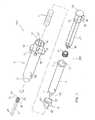
図1は本発明の保護機構と従来の注射器とを図示する軸側投影分解図である。 FIG. 1 is an axial projection exploded view illustrating a protection mechanism of the present invention and a conventional syringe.
図2は図1の保護機構の一部を形成する袖部の軸方向の断面図である。 FIG. 2 is a sectional view in the axial direction of a sleeve portion forming a part of the protection mechanism of FIG.
図3は図1の保護機構の一部を形成するばね接合部材の軸方向の断面図である。 FIG. 3 is a sectional view in the axial direction of a spring joining member forming a part of the protection mechanism of FIG.
図4は保護機構を備えた図1の注射器の特に軸方向の断面を示す図であり、プランジャーの軸部は切断されておらず、 保護タブを有し、針が部分的に分断されて見られる。 FIG. 4 is a view showing a particularly axial section of the syringe of FIG. 1 with a protection mechanism, in which the plunger shaft is not cut, has a protection tab, and the needle is partially cut off. It can be seen.
図5は図4と同様保護機構を備えた注射器の軸方向の断面図であり、プランジャーの軸部の保護タブは取り外され、プランジャーは前進したストロークの端の位置にある。 FIG. 5 is an axial cross-sectional view of a syringe with a protection mechanism, similar to FIG. 4, with the protective tab on the plunger shaft removed and the plunger in the advanced stroke end position.
図6は図4と同様保護機構を備えた注射器の軸方向の断面図であり、針は袖部に保護された保護位置にあり、注射器胴部とプランジャーの軸部とは部分的に分断されて見られる。 FIG. 6 is a sectional view in the axial direction of a syringe provided with a protective mechanism as in FIG. 4, the needle is in a protected position protected by a sleeve, and the syringe barrel and the plunger shaft are partially cut off. Seen to be.
図7は使用中の保護機構を備えた注射器の軸側投影図である。 FIG. 7 is an axial projection of a syringe with a protection mechanism in use.
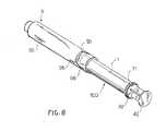
図8は保護位置にある保護機構を備えた注射器の軸側投影図である。 FIG. 8 is an axial projection of a syringe with a protection mechanism in the protected position.
本発明による注射器を使い捨て可能な保護自動注射器に変える取り付け可能な保護機構を、図面を参照して説明する。 An attachable protection mechanism for converting a syringe according to the invention into a disposable protective auto-injector will be described with reference to the drawings.
特に図1を参照すると、参照番号100で全体として示された従来の注射器と参照番号200で全体として示された一揃いの構成要素を含む保護機構とが図示されている。 With particular reference to FIG. 1, a conventional syringe generally indicated by
注射器100は、市場で一般的手に入る注射器であり、注射器胴部1、注射針2、プランジャー4、および軸部41を備えている。 The
注射器胴部1は、円筒形で内部が空洞になっており、円筒形の空間10を規定する(define)。胴部1の後部は外向きに開いており、外向きに放射状に突出した環状のつば11を有する。まったく正反対の位置に、外向きに放射状に突出した二つの舌状体とフランジ(図示せず)とが環状リム11の上に配置され、使用者の指の把持手段を規定する。 The syringe barrel 1 is cylindrical and hollow inside, and defines a cylindrical space 10 (define). The rear part of the trunk 1 is open outward and has an
ヘッド115の胴部1の前縁部は外向きに開き、該円筒形あるいは堆円錐状(frusto-conical)羽根の形をしており、胴部1前部の肩部15を規定するために直径は胴部1よりもはるかに小さい。 The front edge of the body 1 of the
注射針2は、円筒形または堆円錐状で、かつその内部が空洞である注射器胴部のヘッドの羽根を受け入れるための軸方向の空間23を有する針キャリア20の上に据え付けられるか、または中に作りつけられている。針キャリア20は自由端に正反対の位置に放射状に突出している舌状体22を有するつば21を有することが可能である。舌状体22は外ねじと置き換え可能である。針キャップ24は針キャリア20と噛み合い、針2をカバーする。 The
プランジャー4は、注射器胴部1の空間10を滑動できる。プランジャー4は軸部41のヘッド40に設けられる。軸部41は断面が十字になっており、注射中の使用者の指に接続面を提供するディスク状フランジ42の後部まで伸びている。 The plunger 4 can slide in the
後部フランジ42近傍には、作動クラウン(operating crown)またはディスク43が、軸部41の周りに設けられている。保護舌状体45は、軸部41から外向きに縦に放射状に突出しており、後部フランジ42と作動クラウン43との間に配置されている。保護タブ45は、軸部41と破断可能な接続片(connecting strip)46により連結している。この接続片は、弱める線として機能する(acting as a line of weakening )ミシン目の入った材質からなる。このような方法で、使用者は、保護舌状体45を手動ではずすことができる。 In the vicinity of the
作動クラウン43は、軸部41と、あるいは軸部41の後部フランジ42とともに単体につくられてもよい。従来の注射器100の軸部41が作動クラウン 43を有しない場合には上記作動クラウン 43は一揃いの構成要素200を形成する離間した構成要素としてつくられ、図示されているように軸部41に組み立てられてもよい。 The operating
一揃いの構成要素200は袖部5、ばね7、ばね用の接合部材8、および任意で作動クラウン43を備えている。 The
また図3に見られるように、接合部材8は、そこに圧力で取り付けられるように直径が注射器胴部前側の外側の直径とほぼ同じくらいの軸方向孔81を有する円筒形または堆円錐状の胴部を有し、その内部が空洞になっている。接合部材8は、前方の軸方向に円筒形あるいは堆円錐状の羽根82を有し、その直径は肩部84となるように胴部80よりも小さい。羽根82は内部が空洞になっており、内ねじ83を有する。 As can also be seen in FIG. 3, the joining member 8 has a cylindrical or conical shape with an
このように、接合部材8が注射器胴部のヘッドに適合されると、注射器胴部の羽根115は接合部材の羽根82の内部に軸方向に配置され、注射針2の針キャリア20を受け入れるために注射器胴部のヘッドのいわゆるルアー円錐(Luer cone)となるように注射器胴部の羽根115の外側面針支持と針支持部材の羽根82の内面との間に環状の空間を有する。この場合、接合部材8は針2の支持部材として働く。 Thus, when the joining member 8 is adapted to the head of the syringe barrel, the
図2に見られるように、本発明によると、一揃いの構成要素200は参照番号5で示され内部が空洞であり、かつ前部と後部に開いた軸方向孔を有する該円筒状の袖部の形をしている注射器用の保護機構を備えている。袖部5は、直径がより小さく、内側に放射状に突出している環状のつば52となる前部51を有する。袖部胴部の内側の直径は接合部材8の胴部80の外側の直径よりも少し大きいくなっており、接合部材8が注射器胴部1のヘッドに適用されたときに、袖部5が、接合部材8の胴部80の上を軸方向に滑動できるようになっている。 As can be seen in FIG. 2, according to the present invention, a set of
袖部胴部50後部近傍には、使用者の指を置く台となる正反対の外側に、放射状に突出した二つの強固な舌状体あるいはフランジ53がある。 In the vicinity of the rear portion of the
袖部胴部50の後部には、フランジ53に関連して前にも後ろにも二組の縦向きの柔軟性の舌状体56、66がある。 At the rear of the
一組目の舌状体56は、フランジ53の前部に配置され、正反対に配置された二つの舌状体56を有する。前部舌状体56のそれぞれは内側に向けて少し曲げられており、終わりが後部接続面58となる。前部舌状体56のそれぞれは袖部胴部に対し曲げられるように袖部の胴部に作られたほぼU字型をした切りこみによって限定される。 The first set of
二組目の舌状体66は、フランジ53の後部に配置され、正反対に配置された二つの舌状体66を有する。後部舌状体66のそれぞれは内側に向けて少し曲げられており、終わりが前部接続面68となる。後部舌状体66のそれぞれは袖部胴部に対し曲げられるように袖部の胴部に作られたほぼU字型をした切りこみによって限定される。 The second set of
最後に、一揃いの構成要素200は袖部胴部の前部52に格納できるように設計されたらせん状のばね7を含む。実際に、ばね7の外側の直径は袖部胴部5前部51の内側の直径よりも少し小さい。 Finally, the
注射器100の一揃いの構成要素200の組み立てについては、単に例として(purely by way of example)また図4を参照にして以下に述べる。 The assembly of the set of
保護機構200は、予め組み立てられた状態で供給される。つまり、ばね7は、袖部5に挿入されており、袖部5の後部から、ばねの端が袖部5の前部のつば52に当接できるようになっている。そして、ばね用の接合部材8が、袖部5に挿入されており、再び袖部5の後部から接合部材の肩部84がばねの反対側の端に当接できるようになっている。そして、接合部材8を袖部に軽く押し込むと、接合部材の胴部80は、一対の後部舌状体66を通過し、接合部材の後部が袖部の後部舌状体の前部接合面68によって塞がれ、接合部材が袖部から外れるのを防止する。 The
この時点では、予め組み立てられた保護機構200は機械ででも、手動でも従来の注射器100に取り付けることができる。実際に、注射器胴部1を袖部の後部から袖部5に押し込むだけで十分である。このように注射器胴部の羽根115は接合部材8に注射器胴部1の肩部15が接合部材の肩部84に当接するまで挿入される。このような状況において接合部材8は注射器胴部1の前部と一体であり、注射器胴部の内側羽根115と接合部材の外側羽根82とからなるルアー円錐は注射器胴部のヘッド内部に形成される。注射器胴部を前進させ舌状体56を少し外側に曲げさせると、注射器胴部は接合部材8を少し前に押しばねを袖部の前部51に圧縮する。 At this point, the
図4に見られるように、注射器胴部の後端11が袖部の一対の後部舌状体66を通過すると、後部舌状体66の前部接合面68注射器胴部の後端に当接し、注射器胴部がばね7の動きによって袖部5から外れるのを防止する。 As seen in FIG. 4, when the
このような状況においては軸部41に取り付けられた保護タブ45は袖部5の後端に当接し、作動クラウン43が袖部の後部舌状体と協同して保護機構200を駆動させないように軸部41がさらに前進することを防止することを付記しておくべきである。 In such a situation, the
本発明による保護機構付きの注射器100の操作について、図5から8を参照にして以下に述べる。 The operation of the
注射を行う前に使用者は弱める点線(perforated line of weakening)46に沿って保護タブ45を手で裂く。 Prior to making the injection, the user manually tears the
図5に見られるように、プランジャー4が注射器胴部の空間内部の注入行程の端まで到達すると、軸部41の 作動クラウン 43は袖部の柔軟性の後部舌状体66に接触し、上記舌状体66を外向きに曲げる。 As seen in FIG. 5, when the plunger 4 reaches the end of the injection stroke inside the syringe barrel space, the
その結果、注射器胴部の後端11は後部舌状体66の突起部68から解放されると、注射器胴部1に関する袖部5の軸方向の動きはもはや防止できない。このように、解放されたばね7の動きによって袖部5は注射器胴部1に対し軸方向に前進でき、および/または注射器胴部1は袖部5に対し軸方向に後退できる。袖部5の動きはばね7の動きにより自動的に起こり、使用者が手動で介入する必要はないということを付記しておく。 As a result, when the
図7に見られるように、上記袖部5と注射器100の伸縮自在の動きは使用者の手によって制御され調節される。実際に使用者は人差し指と中指とを袖部のフランジ53に、親指をプランジャー軸部の後部フランジ42に置き、袖部5と注射器100との保護位置へのストロークが同時に起こり、そしてこのように注射器1に関する袖部5それぞれの動きの速さを使用者の要求どおりに調節する。 As can be seen in FIG. 7, the telescopic movement of the
図6〜8に見られるように、袖部5のストロークの終わりに、接合部材8の胴部80は、二組の舌状体56と66との間に留まる。つまり、前部舌状体56の後部接合面58は、接合部材の肩部84と当接し、その前方への動きを防止する。一方、後部舌状体66の前部接合面68は、接合部材の胴部80と当接し、その後方への動きを防止する。袖部を強く牽引すると接合部材8は注射器胴部から外れるが、それにもかかわらず針2は、接合部材とともに袖部5の内部に残されたままとなる。 As seen in FIGS. 6-8, at the end of the stroke of the
本発明において袖部5が前進した保護位置にあっても、ばね7は、袖部5の中に保護されたままであるということを付記しておく。 It should be noted that the
さらに本発明において三つだけの付加的な構成要素、すなわち、袖部5、ばね7、および接合部材8を使用すると、胴部1、そこに軸部41を有するプランジャー4およびそこに支持部(support)20を有する針2を含む従来の注射器が保護注射器となるということを付記しておく。さらに、上記作動クラウン43が一体化されていないか、または軸部41とともに単体に作られていない場合には、一揃いの構成要素200は、任意選択でピストンの軸部41に適合される作動クラウン43を備えている。 Furthermore, if only three additional components are used in the present invention, namely the
付随した特許請求の範囲に記載された発明の範囲から外れることなく当業者の手の届く範囲で多くの変更または修正を本発明の当実施様態に与えることが可能である。 Many changes or modifications may be made to this embodiment of the invention without departing from the scope of the invention as set forth in the appended claims without departing from the scope of those skilled in the art.
Claims (18)
Translated fromJapanese注射器胴部(1)の内壁における、注射器が充填された後退位置から注射器が空になった前方位置まで伸びた注入行程を滑動可能なプランジャー(4)と、
ヘッド(115)と噛み合う針キャリア(20)に取り入れられた注射針(2)とを備え、
プランジャーの後部には、手動操作可能であり、かつその後端(42)により注射器胴部から出し可能な軸部(41)が配された注射器(100)に取り付け、使い捨て可能な保護自動注射器にする保護機構(200)であって、
予め組み立て可能であり、かつ、
上記注射器胴部(1)に、滑動可能に取り付けられた袖部(5)と、
上記袖部(5)に格納されたばね(7)と、
上記袖部(5)に格納され、上記注射器胴部(1)の前部と一体化可能な、上記ばね(7)用ばね接合部材(8)と、
を備えたことを特徴とする保護機構(200)。A syringe barrel (1) having a hollow interior and having openings at the front and rear; and
A plunger (4) slidable on the inner wall of the syringe barrel (1) extending from a retracted position filled with the syringe to a forward position where the syringe is empty;
A needle (2) incorporated in a needle carrier (20) that meshes with the head (115);
At the rear of the plunger, it is attached to a syringe (100) which is manually operable and has a shaft (41) which can be taken out from the syringe barrel by its rear end (42). Protection mechanism (200)
Can be assembled in advance, and
A sleeve (5) slidably attached to the syringe barrel (1);
A spring (7) stored in the sleeve (5);
A spring joining member (8) for the spring (7), which is stored in the sleeve (5) and can be integrated with the front part of the syringe barrel (1);
A protection mechanism (200) comprising:
上記係止手段(66、11)は、上記袖部(5)の後部及び上記注射器胴体部(1)に、相互に噛合した状態で配置され、上記袖部が上記ばね(7)の動きに対して注射器を使用する後退位置に係止された状態に維持されており、
プランジャー(4)が注入行程の端部に到達し、上記ばね(7)の動きにより、袖部が上記保護位置へ軸方向に移動可能になったときに、操作部(43)が、上記軸部(41)に配置され、上記係止手段(56)を解除することを特徴とする請求項1および2に記載の機構(200)。While the sleeve (5) is slidably placed on the syringe barrel (1) and moves from the retracted position to use the syringe to a forward position that protects the sleeve (5) the needle (2) The spring (7) is a joint member (8) integrated with the sleeve (5) and the syringe barrel (1) in a compressed state at the front of the sleeve (5). And promotes the axial movement of the sleeve (5) relative to the syringe barrel,
The locking means (66, 11) are arranged in mesh with the rear part of the sleeve part (5) and the syringe body part (1), and the sleeve part is in motion of the spring (7). It is kept locked in the retracted position using the syringe,
When the plunger (4) reaches the end of the injection stroke, and the sleeve (7) is movable in the axial direction to the protected position by the movement of the spring (7), the operating portion (43) 3. Mechanism (200) according to claim 1 and 2, characterized in that it is arranged on the shaft (41) and releases the locking means (56).
注射器胴部(1)の前方部に適合されるように、その内部が空洞になった円柱形または堆円錐状の胴部(80)と、
上記胴部(80)よりも直径が小さくなっている、円柱形または堆円錐状羽根(82)と、
上記胴部から前方に突出している肩部(84)とを備えたことを特徴とする請求項1〜3のいずれか1項に記載の機構(200)。The joining member (8)
A cylindrical or cone-shaped barrel (80) having a hollow interior so as to be fitted to the front of the syringe barrel (1);
A columnar or conical blade (82) having a smaller diameter than the body (80);
The mechanism (200) according to any one of claims 1 to 3, further comprising a shoulder (84) projecting forward from the body.
ばね(7)の一方の端部が、袖部の前部(51)の内側へ突出したつば(52)に当接しており、他方の端部が接合部材の肩部(84)に当接していることを特徴とする請求項4に記載の機構(200)。The spring is a spiral spring (7) disposed at the front (51) of the sleeve so as to surround the blade (82) of the joining member;
One end of the spring (7) is in contact with the collar (52) protruding inward of the front part (51) of the sleeve, and the other end is in contact with the shoulder (84) of the joining member. The mechanism (200) of claim 4, wherein the mechanism (200).
注射器胴部(1)の内壁における、注射器が充填された後退位置から注射器が空になった前方位置まで伸びた注入行程を滑動可能なプランジャー(4)と、
ヘッド(115)と噛合可能な針キャリア(20)に取り入れられた注射針(2)と、
と上記注射器胴部(1)に滑動可能に取り付けられ、注射器を使用する後退位置(針が前方へ突出する位置)から保護する前方位置(針を覆う位置)へ移動する袖部(5)と、
プランジャーの後部には、手動操作可能であり、かつその後端(42)により注射器胴部から出し可能な軸部(41)が配された保護自動注射器(100)であって、
上記注射器胴部(1)の前部と一体化可能な接合部材(8)と、
上記袖部(5)の前部で圧縮された状態で、上記袖部(5)と、上記注射器胴体部(1)と一体化した接合部材(8)との間に配置され、注射器胴部に対して袖部(5)の軸方向の動きを促進するばね手段(7)とを備え、
さらに、
上記袖部(5)の後部及び上記注射器胴体部(1)に、相互に噛合した状態で配置され、上記袖部が上記ばね(7)の動きに対して注射器を使用する後退位置に係止された状態に維持する係止手段(66、11)と、
上記軸部(41)に配置され、プランジャー(4)が注入行程の端部に到達し、上記ばね(7)の動きにより、袖部が上記保護位置へ軸方向に移動可能になったときに、上記係止手段(56)を解除する操作部(43)と、
を備えたことを特徴とする保護自動注射器。A syringe barrel (1) having a hollow interior and having openings at the front and rear; and
A plunger (4) capable of sliding an injection stroke extending from a retracted position filled with the syringe to a forward position where the syringe is empty, on the inner wall of the syringe barrel (1);
An injection needle (2) incorporated in a needle carrier (20) that can mesh with the head (115);
And a sleeve (5) that is slidably attached to the syringe barrel (1) and moves from a retracted position (position where the needle protrudes forward) using the syringe to a forward position (position covering the needle). ,
A protective auto-injector (100) provided at the rear part of the plunger with a shaft part (41) which can be manually operated and can be taken out of the syringe barrel by its rear end (42),
A joining member (8) that can be integrated with the front portion of the syringe barrel (1);
In a state of being compressed at the front part of the sleeve part (5), the sleeve part (5) is disposed between the sleeve part (5) and the joint member (8) integrated with the syringe body part (1). Spring means (7) for promoting the axial movement of the sleeve (5) against
further,
The sleeve (5) is disposed in mesh with the back of the sleeve (5) and the syringe barrel (1), and the sleeve is locked in a retracted position using the syringe against the movement of the spring (7). Locking means (66, 11) for maintaining the locked state;
When the plunger (4) reaches the end of the injection stroke when the sleeve (41) is moved to the protected position in the axial direction by the movement of the spring (7). And an operation portion (43) for releasing the locking means (56),
A protective automatic injector characterized by comprising:
注射器胴部(1)の前方部に適合されるように、その内部が空洞になった円柱形または堆円錐状の胴部(80)と、
上記胴部(80)よりも直径が小さくなっている、円柱形または堆円錐状羽根(82)と、
上記胴部から前方に突出している肩部(84)とを備えたことを特徴とする請求項12に記載の注射器(100)。The joining member (8)
A cylindrical or cone-shaped barrel (80) having a hollow interior so as to be fitted to the front of the syringe barrel (1);
A columnar or conical blade (82) having a smaller diameter than the body (80);
The syringe (100) according to claim 12, further comprising a shoulder (84) projecting forward from the barrel.
ばね(7)の一方の端部が、袖部の前部(51)の内側へ突出したつば(52)に当接しており、他方の端部が接合部材の肩部(84)に当接していることを特徴とする請求項13に記載の注射器。The spring means is a spiral spring (7) disposed on the front part (51) of the sleeve so as to surround the blade (82) of the joining member,
One end of the spring (7) is in contact with the collar (52) protruding inward of the front part (51) of the sleeve, and the other end is in contact with the shoulder (84) of the joining member. The syringe according to claim 13, wherein
上記係止手段(56、66)は、上記袖部(5)に形成された、一対の後部舌状体(66)とそれに対向した前部舌状体(56)とを備え、上記前部舌状体(56)は、接合部材(8)の肩部(84)に対して当接可能な後部接続面(58)を有し、上記後部舌状体(66)は接合部材の胴部の後端(80)に対して当接可能な前部接続面(68)を有することを特徴とする請求項12〜14のいずれか1項に記載の注射器。The sleeve (5) is formed with locking means (56, 66) for cooperating with the joining member (8) to lock the sleeve when in the forward protected position,
The locking means (56, 66) includes a pair of rear tongues (66) formed on the sleeve (5) and a front tongue (56) opposed thereto, and the front part. The tongue-like body (56) has a rear connection surface (58) that can come into contact with the shoulder (84) of the joining member (8), and the rear tongue-like body (66) is a trunk portion of the joining member. 15. Syringe according to any one of claims 12 to 14, characterized in that it has a front connection surface (68) which can abut against the rear end (80).
Applications Claiming Priority (1)
| Application Number | Priority Date | Filing Date | Title |
|---|---|---|---|
| PCT/IT2002/000730WO2004045685A1 (en) | 2002-11-18 | 2002-11-18 | Guard mechanism attachable to standard syringe to transform it into a safety syringe |
Publications (1)
| Publication Number | Publication Date |
|---|---|
| JP2006506166Atrue JP2006506166A (en) | 2006-02-23 |
Family
ID=32321390
Family Applications (1)
| Application Number | Title | Priority Date | Filing Date |
|---|---|---|---|
| JP2004553076APendingJP2006506166A (en) | 2002-11-18 | 2002-11-18 | Protection mechanism attached to a standard syringe to make it a disposable protective syringe |
Country Status (12)
| Country | Link |
|---|---|
| US (1) | US20060200077A1 (en) |
| EP (1) | EP1562661B1 (en) |
| JP (1) | JP2006506166A (en) |
| CN (1) | CN100482290C (en) |
| AT (1) | ATE434457T1 (en) |
| AU (1) | AU2002358977A1 (en) |
| CA (1) | CA2506465A1 (en) |
| DE (1) | DE60232750D1 (en) |
| EG (1) | EG23689A (en) |
| MX (1) | MXPA05005302A (en) |
| TW (1) | TW200502021A (en) |
| WO (1) | WO2004045685A1 (en) |
Cited By (5)
| Publication number | Priority date | Publication date | Assignee | Title |
|---|---|---|---|---|
| WO2008133305A1 (en)* | 2007-04-24 | 2008-11-06 | Arte Corporation | Injector doubling as container |
| JP2011036490A (en)* | 2009-08-13 | 2011-02-24 | Arte Corp | Syringe-cum-container |
| JP2020524019A (en)* | 2017-06-16 | 2020-08-13 | クリーデンス メドシステムズ, インコーポレイテッドCredence MedSystems, Inc. | Safety syringe system and method |
| US11419991B2 (en) | 2018-11-13 | 2022-08-23 | Credence Medsystems, Inc. | System and method for microdose injection |
| US11883635B2 (en) | 2020-06-17 | 2024-01-30 | Credence MedSystems | System and method for microdose injection |
Families Citing this family (50)
| Publication number | Priority date | Publication date | Assignee | Title |
|---|---|---|---|---|
| US7544188B2 (en) | 2001-07-19 | 2009-06-09 | Intelliject, Inc. | Medical injector |
| FR2852851B1 (en)* | 2003-03-25 | 2006-01-06 | Sedat | NEEDLE PROTECTION DEVICE FOR SYRINGE, AND INJECTION DEVICE COMPRISING SYRINGE AND PROTECTIVE DEVICE |
| FR2861310B1 (en)* | 2003-10-22 | 2006-09-22 | Plastef Investissements | SECURE INJECTION SYRINGE DEVICE |
| FR2865408B1 (en)* | 2004-01-22 | 2006-03-10 | P2A | SAFETY CONNECTOR NEEDLE |
| CN100553698C (en)* | 2004-03-16 | 2009-10-28 | 格兰诺德控股有限公司 | Single use retractable syringe |
| AU2005223869B8 (en)* | 2004-03-16 | 2011-09-01 | Q Stat Ip Pty Ltd | Single use retractable syringe |
| US7294119B2 (en) | 2004-06-10 | 2007-11-13 | Safety Syringes, Inc. | Passive delivery system diluents mixing and delivery |
| WO2006057636A1 (en) | 2004-11-22 | 2006-06-01 | Intelliject, Llc | Devices, systems, and methods for medicament delivery |
| US11590286B2 (en) | 2004-11-22 | 2023-02-28 | Kaleo, Inc. | Devices, systems and methods for medicament delivery |
| US7648483B2 (en) | 2004-11-22 | 2010-01-19 | Intelliject, Inc. | Devices, systems and methods for medicament delivery |
| US7947017B2 (en) | 2004-11-22 | 2011-05-24 | Intelliject, Inc. | Devices, systems and methods for medicament delivery |
| US7648482B2 (en) | 2004-11-22 | 2010-01-19 | Intelliject, Inc. | Devices, systems, and methods for medicament delivery |
| US10737028B2 (en) | 2004-11-22 | 2020-08-11 | Kaleo, Inc. | Devices, systems and methods for medicament delivery |
| US8361026B2 (en) | 2005-02-01 | 2013-01-29 | Intelliject, Inc. | Apparatus and methods for self-administration of vaccines and other medicaments |
| US7731686B2 (en) | 2005-02-01 | 2010-06-08 | Intelliject, Inc. | Devices, systems and methods for medicament delivery |
| US8231573B2 (en) | 2005-02-01 | 2012-07-31 | Intelliject, Inc. | Medicament delivery device having an electronic circuit system |
| US9022980B2 (en) | 2005-02-01 | 2015-05-05 | Kaleo, Inc. | Medical injector simulation device |
| AU2006210865B2 (en) | 2005-02-01 | 2008-12-04 | Kaleo, Inc. | Devices, systems, and methods for medicament delivery |
| US8206360B2 (en) | 2005-02-01 | 2012-06-26 | Intelliject, Inc. | Devices, systems and methods for medicament delivery |
| JP4767655B2 (en)* | 2005-10-28 | 2011-09-07 | テルモ株式会社 | Protector and needle set |
| US8225227B2 (en)* | 2007-01-19 | 2012-07-17 | Microsoft Corporation | Managing display of user interfaces |
| EP2125075A2 (en) | 2007-01-22 | 2009-12-02 | Intelliject, Inc. | Medical injector with compliance tracking and monitoring |
| ITMI20070500A1 (en)* | 2007-03-13 | 2008-09-14 | Sergio Restelli | SAFETY MECHANISM FOR SYRINGE ASSEMBLY METHOD AND RELATIVE SAFETY SYRINGE |
| DE202007005394U1 (en)* | 2007-04-13 | 2007-08-09 | B. Braun Melsungen Ag | safety syringe |
| US9044378B2 (en) | 2007-05-31 | 2015-06-02 | Safety Syringes, Inc. | Anti-needle stick safety device or system for use with drugs requiring reconstitution |
| FR2922455B1 (en)* | 2007-10-23 | 2010-10-29 | Plastef Investissements | SYRINGE DEVICE COMPRISING A SYRINGE BODY AND A SUPPORT SLEEVE. |
| US8105292B2 (en) | 2008-02-11 | 2012-01-31 | Safety Syringes, Inc. | Reconstitution means for safety device |
| USD994111S1 (en) | 2008-05-12 | 2023-08-01 | Kaleo, Inc. | Medicament delivery device cover |
| ATE518557T1 (en)* | 2008-07-08 | 2011-08-15 | Kunststofftechnik Waidhofen An Der Thaya Gmbh | CANNULA PROTECTION AND DISPOSABLE SYRINGE SYSTEM |
| US20100076370A1 (en) | 2008-09-23 | 2010-03-25 | Infusion Advancements, LLC. | Apparatus and methods for purging catheter systems |
| US8627816B2 (en) | 2011-02-28 | 2014-01-14 | Intelliject, Inc. | Medicament delivery device for administration of opioid antagonists including formulations for naloxone |
| US9173999B2 (en) | 2011-01-26 | 2015-11-03 | Kaleo, Inc. | Devices and methods for delivering medicaments from a multi-chamber container |
| US8939943B2 (en) | 2011-01-26 | 2015-01-27 | Kaleo, Inc. | Medicament delivery device for administration of opioid antagonists including formulations for naloxone |
| US9022990B2 (en) | 2011-04-04 | 2015-05-05 | Tech Group Europe Limited | Needle safety shield |
| US9522235B2 (en) | 2012-05-22 | 2016-12-20 | Kaleo, Inc. | Devices and methods for delivering medicaments from a multi-chamber container |
| US9050416B2 (en) | 2012-11-01 | 2015-06-09 | Tech Group Europe Limited | Needle Safety device with floating ring |
| GB2526948A (en) | 2012-12-27 | 2015-12-09 | Kaleo Inc | Systems for locating and interacting with medicament delivery devices |
| WO2014153599A1 (en)* | 2013-03-25 | 2014-10-02 | Adam Timothy John | Auto-retractible syringe |
| CN103736175B (en)* | 2014-02-12 | 2015-08-19 | 刘友红 | Disposable anti-stabbed syringe |
| US9517307B2 (en) | 2014-07-18 | 2016-12-13 | Kaleo, Inc. | Devices and methods for delivering opioid antagonists including formulations for naloxone |
| US10695495B2 (en) | 2015-03-24 | 2020-06-30 | Kaleo, Inc. | Devices and methods for delivering a lyophilized medicament |
| CA2990950A1 (en) | 2015-06-30 | 2017-01-05 | Kaleo, Inc. | Auto-injectors for administration of a medicament within a prefilled syringe |
| WO2018119218A1 (en) | 2016-12-23 | 2018-06-28 | Kaleo, Inc. | Medicament delivery device and methods for delivering drugs to infants and children |
| CA3046354A1 (en) | 2017-01-17 | 2018-07-26 | Kaleo, Inc. | Medicament delivery devices with wireless connectivity and event detection |
| US11929160B2 (en) | 2018-07-16 | 2024-03-12 | Kaleo, Inc. | Medicament delivery devices with wireless connectivity and compliance detection |
| CA3145580A1 (en) | 2019-08-09 | 2021-02-18 | Kaleo, Inc. | Devices and methods for delivery of substances within a prefilled syringe |
| KR102387319B1 (en)* | 2020-07-29 | 2022-04-22 | (주)픽스앤케어 | Medical syringe safety box and safety syringe equipped with the same |
| US12268847B1 (en) | 2021-02-10 | 2025-04-08 | Kaleo, Inc. | Devices and methods for delivery of substances within a medicament container |
| CN117281978A (en)* | 2023-07-28 | 2023-12-26 | 梵颖(上海)生物科技有限公司 | Syringe protection device and safety syringe |
| CN117281979A (en)* | 2023-07-28 | 2023-12-26 | 梵颖(上海)生物科技有限公司 | Syringe protection device and safety syringe |
Family Cites Families (13)
| Publication number | Priority date | Publication date | Assignee | Title |
|---|---|---|---|---|
| US4737144A (en)* | 1987-03-09 | 1988-04-12 | Choksi Pradip V | Syringe with selectively exposed and enveloped needle |
| US5843041A (en)* | 1989-03-02 | 1998-12-01 | Hake; Lawrence W. | Hypodermic needle guard and method to prevent needle stick injuries |
| ES2074168T3 (en)* | 1990-03-08 | 1995-09-01 | Blue Star Corp Sa | SELF-SWEEPING NEEDLE SYRINGE. |
| US5376080A (en)* | 1991-01-30 | 1994-12-27 | Petrussa; Gian L. | Single use retractable needle syringe |
| US5273541A (en)* | 1992-08-03 | 1993-12-28 | Robert Malenchek | Safety syringe |
| US5433712A (en)* | 1993-06-10 | 1995-07-18 | Donald E. Stiles | Self-sheathing hypodermic syringe |
| FR2764195B1 (en)* | 1997-06-10 | 1999-10-15 | Blue Star Corp | SELF-RETRACTING NEEDLE SYRINGE |
| IT1304761B1 (en)* | 1998-01-20 | 2001-03-29 | Nardino Righi | DISPOSABLE SAFETY SYRINGE. |
| US6616639B2 (en)* | 1998-04-17 | 2003-09-09 | Becton, Dickinson And Company | Safety shield system for syringes |
| GB0003790D0 (en)* | 2000-02-18 | 2000-04-05 | Astrazeneca Uk Ltd | Medical device |
| US6471677B2 (en)* | 2000-04-06 | 2002-10-29 | Gem Plastics, Inc. | Fluid collection device with protective shield |
| US6613022B1 (en)* | 2000-05-05 | 2003-09-02 | Safety Syringes, Inc. | Passive needle guard for syringes |
| EP1291029A1 (en)* | 2001-09-10 | 2003-03-12 | Sergio Restelli | Automatic safety syringe |
- 2002
- 2002-11-18JPJP2004553076Apatent/JP2006506166A/enactivePending
- 2002-11-18CACA002506465Apatent/CA2506465A1/ennot_activeAbandoned
- 2002-11-18WOPCT/IT2002/000730patent/WO2004045685A1/enactiveApplication Filing
- 2002-11-18CNCNB028299191Apatent/CN100482290C/ennot_activeExpired - Fee Related
- 2002-11-18ATAT02793322Tpatent/ATE434457T1/ennot_activeIP Right Cessation
- 2002-11-18MXMXPA05005302Apatent/MXPA05005302A/ennot_activeApplication Discontinuation
- 2002-11-18AUAU2002358977Apatent/AU2002358977A1/ennot_activeAbandoned
- 2002-11-18USUS10/535,198patent/US20060200077A1/ennot_activeAbandoned
- 2002-11-18DEDE60232750Tpatent/DE60232750D1/ennot_activeExpired - Fee Related
- 2002-11-18EPEP02793322Apatent/EP1562661B1/ennot_activeExpired - Lifetime
- 2003
- 2003-11-17TWTW092132127Apatent/TW200502021A/enunknown
- 2003-11-18EGEGNA2003000003patent/EG23689A/enactive
Cited By (8)
| Publication number | Priority date | Publication date | Assignee | Title |
|---|---|---|---|---|
| WO2008133305A1 (en)* | 2007-04-24 | 2008-11-06 | Arte Corporation | Injector doubling as container |
| JP2011036490A (en)* | 2009-08-13 | 2011-02-24 | Arte Corp | Syringe-cum-container |
| JP2020524019A (en)* | 2017-06-16 | 2020-08-13 | クリーデンス メドシステムズ, インコーポレイテッドCredence MedSystems, Inc. | Safety syringe system and method |
| JP7098171B2 (en) | 2017-06-16 | 2022-07-11 | クリーデンス メドシステムズ,インコーポレイテッド | Safety syringe system and method |
| US11964141B2 (en) | 2017-06-16 | 2024-04-23 | Credence Medsystems, Inc. | System and method for safety syringe |
| US11419991B2 (en) | 2018-11-13 | 2022-08-23 | Credence Medsystems, Inc. | System and method for microdose injection |
| US12329953B2 (en) | 2018-11-13 | 2025-06-17 | Credence Medsystems, Inc. | System and method for multiple site injection |
| US11883635B2 (en) | 2020-06-17 | 2024-01-30 | Credence MedSystems | System and method for microdose injection |
Also Published As
| Publication number | Publication date |
|---|---|
| CA2506465A1 (en) | 2004-06-03 |
| EG23689A (en) | 2007-05-13 |
| WO2004045685A1 (en) | 2004-06-03 |
| ATE434457T1 (en) | 2009-07-15 |
| TW200502021A (en) | 2005-01-16 |
| AU2002358977A1 (en) | 2004-06-15 |
| EP1562661A1 (en) | 2005-08-17 |
| US20060200077A1 (en) | 2006-09-07 |
| EP1562661B1 (en) | 2009-06-24 |
| DE60232750D1 (en) | 2009-08-06 |
| CN1694740A (en) | 2005-11-09 |
| CN100482290C (en) | 2009-04-29 |
| MXPA05005302A (en) | 2005-08-16 |
Similar Documents
| Publication | Publication Date | Title |
|---|---|---|
| JP2006506166A (en) | Protection mechanism attached to a standard syringe to make it a disposable protective syringe | |
| US12263328B2 (en) | Medicament delivery device | |
| US20240058535A1 (en) | Safety mechanism for an autoinjector | |
| US4966593A (en) | Disposable hypodermic syringe with retractable needle | |
| US5433712A (en) | Self-sheathing hypodermic syringe | |
| US6926697B2 (en) | Adaptor for converting a non-safety syringe into a safety syringe | |
| US6494863B1 (en) | One-use retracting syringe with positive needle retention | |
| US5562624A (en) | Non-reusable safety syringe | |
| JP5275031B2 (en) | Automatic injection device with a needle protection cap having an inner sleeve and an outer sleeve | |
| JP4068192B2 (en) | Non-reusable telescopic safety syringe and its usage | |
| US5910131A (en) | Non-reusable retractable safety syringe | |
| US8617105B2 (en) | Safety assembly for a syringe | |
| EP1397172B1 (en) | Safety shield system for prefilled syringes | |
| IL186371A (en) | Injection device | |
| JPH05500621A (en) | Syringe | |
| US5211630A (en) | Hypodermic syringe | |
| US6692470B2 (en) | Single-use hypodermic syringe having a removable needle assembly | |
| JP6752960B2 (en) | How to assemble a drug container holder and a drug delivery device for a drug delivery device | |
| EP1362609A1 (en) | Disposable safety syringe with automatically guided outer sleeve | |
| WO2003009891A1 (en) | Single-use syringe | |
| US12121703B2 (en) | Fluid injection device | |
| EP1371382A1 (en) | Safety syringe having a protective sleeve | |
| RU2320374C2 (en) | Protection device attached to ordinary syringe to transform it to safe syringe | |
| WO2012004804A1 (en) | Retractable syringe | |
| WO2001072363A1 (en) | Retractable syringe |
Legal Events
| Date | Code | Title | Description |
|---|---|---|---|
| A521 | Request for written amendment filed | Free format text:JAPANESE INTERMEDIATE CODE: A821 Effective date:20051019 |