JP2006505014A - Multiple obliquely oriented plate compensators for multiple projection display systems - Google Patents
Multiple obliquely oriented plate compensators for multiple projection display systemsDownload PDFInfo
- Publication number
- JP2006505014A JP2006505014AJP2004550302AJP2004550302AJP2006505014AJP 2006505014 AJP2006505014 AJP 2006505014AJP 2004550302 AJP2004550302 AJP 2004550302AJP 2004550302 AJP2004550302 AJP 2004550302AJP 2006505014 AJP2006505014 AJP 2006505014A
- Authority
- JP
- Japan
- Prior art keywords
- projection system
- panel
- anisotropy
- oblique
- oblique orientation
- Prior art date
- Legal status (The legal status is an assumption and is not a legal conclusion. Google has not performed a legal analysis and makes no representation as to the accuracy of the status listed.)
- Pending
Links
Images


Classifications
- G—PHYSICS
- G02—OPTICS
- G02F—OPTICAL DEVICES OR ARRANGEMENTS FOR THE CONTROL OF LIGHT BY MODIFICATION OF THE OPTICAL PROPERTIES OF THE MEDIA OF THE ELEMENTS INVOLVED THEREIN; NON-LINEAR OPTICS; FREQUENCY-CHANGING OF LIGHT; OPTICAL LOGIC ELEMENTS; OPTICAL ANALOGUE/DIGITAL CONVERTERS
- G02F1/00—Devices or arrangements for the control of the intensity, colour, phase, polarisation or direction of light arriving from an independent light source, e.g. switching, gating or modulating; Non-linear optics
- G02F1/01—Devices or arrangements for the control of the intensity, colour, phase, polarisation or direction of light arriving from an independent light source, e.g. switching, gating or modulating; Non-linear optics for the control of the intensity, phase, polarisation or colour
- G02F1/13—Devices or arrangements for the control of the intensity, colour, phase, polarisation or direction of light arriving from an independent light source, e.g. switching, gating or modulating; Non-linear optics for the control of the intensity, phase, polarisation or colour based on liquid crystals, e.g. single liquid crystal display cells
- G02F1/133—Constructional arrangements; Operation of liquid crystal cells; Circuit arrangements
- G02F1/1333—Constructional arrangements; Manufacturing methods
- G02F1/1335—Structural association of cells with optical devices, e.g. polarisers or reflectors
- G02F1/13363—Birefringent elements, e.g. for optical compensation
- G02F1/133632—Birefringent elements, e.g. for optical compensation with refractive index ellipsoid inclined relative to the LC-layer surface
- G—PHYSICS
- G02—OPTICS
- G02B—OPTICAL ELEMENTS, SYSTEMS OR APPARATUS
- G02B5/00—Optical elements other than lenses
- G02B5/30—Polarising elements
- G02B5/3083—Birefringent or phase retarding elements
- H—ELECTRICITY
- H04—ELECTRIC COMMUNICATION TECHNIQUE
- H04N—PICTORIAL COMMUNICATION, e.g. TELEVISION
- H04N9/00—Details of colour television systems
- H04N9/12—Picture reproducers
- H04N9/31—Projection devices for colour picture display, e.g. using electronic spatial light modulators [ESLM]
- H04N9/3102—Projection devices for colour picture display, e.g. using electronic spatial light modulators [ESLM] using two-dimensional electronic spatial light modulators
- H04N9/3105—Projection devices for colour picture display, e.g. using electronic spatial light modulators [ESLM] using two-dimensional electronic spatial light modulators for displaying all colours simultaneously, e.g. by using two or more electronic spatial light modulators
- H—ELECTRICITY
- H04—ELECTRIC COMMUNICATION TECHNIQUE
- H04N—PICTORIAL COMMUNICATION, e.g. TELEVISION
- H04N9/00—Details of colour television systems
- H04N9/12—Picture reproducers
- H04N9/31—Projection devices for colour picture display, e.g. using electronic spatial light modulators [ESLM]
- H04N9/3141—Constructional details thereof
- H04N9/315—Modulator illumination systems
- G—PHYSICS
- G02—OPTICS
- G02F—OPTICAL DEVICES OR ARRANGEMENTS FOR THE CONTROL OF LIGHT BY MODIFICATION OF THE OPTICAL PROPERTIES OF THE MEDIA OF THE ELEMENTS INVOLVED THEREIN; NON-LINEAR OPTICS; FREQUENCY-CHANGING OF LIGHT; OPTICAL LOGIC ELEMENTS; OPTICAL ANALOGUE/DIGITAL CONVERTERS
- G02F2413/00—Indexing scheme related to G02F1/13363, i.e. to birefringent elements, e.g. for optical compensation, characterised by the number, position, orientation or value of the compensation plates
- G02F2413/08—Indexing scheme related to G02F1/13363, i.e. to birefringent elements, e.g. for optical compensation, characterised by the number, position, orientation or value of the compensation plates with a particular optical axis orientation
- H—ELECTRICITY
- H04—ELECTRIC COMMUNICATION TECHNIQUE
- H04N—PICTORIAL COMMUNICATION, e.g. TELEVISION
- H04N5/00—Details of television systems
- H04N5/74—Projection arrangements for image reproduction, e.g. using eidophor
- H04N5/7416—Projection arrangements for image reproduction, e.g. using eidophor involving the use of a spatial light modulator, e.g. a light valve, controlled by a video signal
- H04N5/7441—Projection arrangements for image reproduction, e.g. using eidophor involving the use of a spatial light modulator, e.g. a light valve, controlled by a video signal the modulator being an array of liquid crystal cells
Landscapes
- Physics & Mathematics (AREA)
- General Physics & Mathematics (AREA)
- Optics & Photonics (AREA)
- Engineering & Computer Science (AREA)
- Multimedia (AREA)
- Signal Processing (AREA)
- Nonlinear Science (AREA)
- Mathematical Physics (AREA)
- Chemical & Material Sciences (AREA)
- Crystallography & Structural Chemistry (AREA)
- Liquid Crystal (AREA)
- Polarising Elements (AREA)
Abstract
Translated fromJapaneseDescription
Translated fromJapanese本発明は、全般的には複数の補償器に関し、より具体的には複数の液晶投写型ディスプレイシステムのための複数の斜め配向プレート補償器に関する。また、本願は、ジャンミン・チェン、マイケル・G・ロビンソン、およびゲリー・D・シャープを複数の発明者とし、本願の譲受人であるカラーリンク社を譲渡人とする「複数の補償器および複数の方法」と題する2002年10月30日提出の米国特許第60/422,437号仮出願からの優先権を主張する。あらゆる目的のために、この仮出願の内容全体を本願明細書に引用したものとする。The present invention relates generally to a plurality of compensators, and more specifically to a plurality of oblique alignment plate compensators for a plurality of liquid crystal projection display systems. In addition, the present application is a “multiple compensator and a plurality of multi-inventors” with Jeanmin Chen, Michael G. Robinson, and Gerry D. Sharp as inventors, and the assignee of the present application as Colorlink. Claims priority from US Provisional Application No. 60 / 422,437, filed Oct. 30, 2002, entitled "Method". For all purposes, the entire content of this provisional application is incorporated herein by reference.
複数の投写型システムに対してコントラストの継続的向上が求められている一方で、投写型システム市場ではより費用効率の高い複数の構成要素および複数のシステム構成が望まれている。これら複数の投写型システムは、赤色、緑色、および青色の光(すなわち、複数の原色)または他の複数の光スペクトルを変調するために複数の液晶パネルを使用し、これら複数の液晶パネルを補償するためにパネル1枚につき1枚または2枚のリターダ膜を使用する。While continuous improvement in contrast is desired for multiple projection systems, multiple cost components and multiple system configurations are desired in the projection system market. These multiple projection systems use multiple liquid crystal panels to modulate red, green, and blue light (ie, multiple primary colors) or other multiple light spectra and compensate for these multiple liquid crystal panels To do this, one or two retarder films are used per panel.
より安価で低コントラストの複数の投写型システムでは、パネル1枚につき単一のリターダ膜を使用して補償を行うが、より高価で高コントラストの複数の投写型システムでは、1枚のパネルの各側に1枚ずつリターダ膜を使用して補償を行う。ただし、既存の複数の補償手法では、市場が複数の投写型システムに求めているコントラストの向上およびコストの制限に対応できない。Multiple projection systems with lower cost and lower contrast use a single retarder film for compensation per panel, while more expensive and higher contrast projection systems use a single panel for each panel. Compensate using one retarder film on each side. However, the existing compensation methods cannot cope with the improvement in contrast and cost restrictions that the market demands for a plurality of projection systems.
本願明細書では、複数の液晶ディスプレイ投写型システム向けの1つの補償方式のための複数の補償器の製造方法、および複数の補償器について説明する。一実施態様によると、この補償方式は、方位平均コントラストを向上し、また複数の非投写型システムに共通する特定の方位依存コントラスト要件による制約をほぼ受けることがない。開示されている複数の補償方式は、法線入射光の偏光状態を維持しながら、複数の法線外入射光の偏光状態を調整する。特定の複数の実施態様においては、複数の法線外入射光線の偏光状態を補正するために、正の異方性多層液晶ポリマー層を複数使用する。In the present specification, a method of manufacturing a plurality of compensators for a single compensation method for a plurality of liquid crystal display projection type systems and a plurality of compensators will be described. According to one embodiment, this compensation scheme improves azimuth average contrast and is substantially unconstrained by specific azimuth dependent contrast requirements common to multiple non-projection systems. The disclosed plurality of compensation methods adjust the polarization state of the plurality of off-normal incidence light while maintaining the polarization state of the normal incidence light. In certain embodiments, a plurality of positive anisotropic multilayer liquid crystal polymer layers are used to correct the polarization state of a plurality of off-normal incidence rays.
開示されている複数の実施態様においては、投写型システムの製造工程を簡略化し、複数の製造コストを削減するために、複数のディスプレイパネルの一方の側に複数のスプレイ配向補償器を配置する1つの補償方式も提供される。この実施態様は、平均コントラストを維持し、かつ方位平均コントラストを向上させる。複数のマイクロレンズアレイを有する複数のシステムの性能を向上するために、複数のスプレイ配向補償器をパネルの低F値側(画像側)に配置しうる。別の実施態様においては、複数のディスプレイパネルの両側にそれぞれ補償器を配置することができる。 In the disclosed embodiments, a plurality of splay alignment compensators are arranged on one side of a plurality of display panels in order to simplify the manufacturing process of the projection system and reduce the manufacturing costs. Two compensation schemes are also provided. This embodiment maintains the average contrast and improves the azimuth average contrast. In order to improve the performance of a plurality of systems having a plurality of microlens arrays, a plurality of splay alignment compensators can be arranged on the low F value side (image side) of the panel. In another embodiment, compensators can be placed on each side of the plurality of display panels.
さらに複数の実施態様においては、スプレイ配向させた正の異方性多層構造を複数有する複数の補償器を開示する。複数の多層構造を単一の基板上に製造することも、1つまたは複数の層の面同士をさまざまな接着剤を用いて接合してそれぞれ別の基板上に製造することもできる。複数の多層構造をそれぞれ別の基板上に製造する場合は、ほぼ完成した複数の構成要素を対にすることによって、複数の反射防止被膜を複数の液晶ポリマー層に直接施す必要がなくなるので、総合的な歩留まりが向上する。 Further, in embodiments, a plurality of compensators having a plurality of splay-oriented positive anisotropic multilayer structures are disclosed. Multiple multilayer structures can be fabricated on a single substrate, or the surfaces of one or more layers can be fabricated on different substrates by bonding with various adhesives. When manufacturing multiple multilayer structures on different substrates, it is not necessary to apply multiple anti-reflective coatings directly to multiple liquid crystal polymer layers by pairing nearly completed multiple components. Yield is improved.
開示されている複数の実施態様は、1つのZ成分を含む1つの光学軸を有する1つの補償器を用いた1つの補償方式をさらに提供する。この特性を有する複数の補償プレートは、複数の斜め配向プレート(「Oプレート」)補償器を含む。このような複数のOプレート補償器は、ホモジニアス配向またはスプレイ配向にしてもよく、また正、負、または二軸異方性を有しうる。複数のスプレイ配向Oプレートは、各界面に1つの異なるプレチルト角を設けることによって得られる。あるいは、複数のOプレートは、ツイストなど、ホモジニアス以外の1つの配向を有してもよい。たとえば、1つのツイスト配向の液晶Oプレート補償器にしてもよい。 The disclosed embodiments further provide one compensation scheme using one compensator having one optical axis that includes one Z component. A plurality of compensation plates having this characteristic includes a plurality of obliquely oriented plate ("O-plate") compensators. A plurality of such O-plate compensators may be homogeneous or splayed and may have positive, negative, or biaxial anisotropy. Multiple splay alignment O-plates are obtained by providing one different pretilt angle at each interface. Alternatively, the plurality of O plates may have one orientation other than homogeneous, such as twist. For example, a single twist alignment liquid crystal O-plate compensator may be used.
複数の投写型システムのシーケンシャルコントラストの継続的向上が求められている理由の一部は、デジタル光処理技術による複数の投写型システムの高性能化による。複数の高温多結晶シリコン(HTPS)ツイストネマチック液晶ディスプレイなどの複数の液晶パネルは、本質的に透過性であり、1つの小さな対角寸法(1.2インチ未満、つまり3.1cm未満)を有する。これら複数のパネルは、1つのツイストネマチック液晶配向を使用し、1つのノーマリホワイトモードで動作し、偏光された光はラビング方向に並行に導入される、つまりeモードで動作する。ただし、本補償方式はeモードおよびoモードの両方に有効である。eモードの場合はLCのラビング方向は偏光子の方向に並行であり、一方oモードの場合はLCのラビング方向は偏光子の方向に直角である。複数の投写型システムは、ランプの発光を効率的に利用するために、入力側のF値を2.5にして動作するのが一般的である。これら複数の投写型システムが複数のマイクロレンズアレイを含む場合、画像光ははるかに低いF値で透過される。このような複数のシステムのコントラストは、マイクロレンズアレイの有無に拘わらず、法線入射の場合は極めて高い。ただし、複数の法線外入射光線では、入射角と方位角とに応じて1つのダイレクタ分布が決まる。この分布は、小さな幾何学的ゆがみと相まって、1つの検光偏光子を透過する光の角度を決める。コントラストをランプの有効角スペクトルにわたって平均化すると、コントラストが大幅に劣化しうる。したがって、法線入射光に対しては零補正を行う一方で、法線外入射光線に対しては偏光状態を補正する複数の補償プレートを導入すると都合がよい。Part of the reason for the continuous improvement of the sequential contrast of a plurality of projection systems is due to the high performance of the plurality of projection systems by digital light processing technology. Multiple liquid crystal panels, such as multiple high temperature polycrystalline silicon (HTPS) twisted nematic liquid crystal displays, are inherently transmissive and have one small diagonal dimension (less than 1.2 inches or 3.1 cm). . These multiple panels use one twisted nematic liquid crystal alignment, operate in one normally white mode, and polarized light is introduced in parallel to the rubbing direction, ie, operates in e mode. However, this compensation method is effective for both the e mode and the o mode. In the e mode, the LC rubbing direction is parallel to the polarizer direction, while in the o mode, the LC rubbing direction is perpendicular to the polarizer direction. In order to efficiently use the light emitted from the lamp, the plurality of projection systems generally operate with an input F value of 2.5. If these multiple projection systems include multiple microlens arrays, the image light is transmitted at a much lower F value. The contrast of such a plurality of systems is extremely high in the case of normal incidence regardless of the presence or absence of the microlens array. However, for a plurality of off-normal incidence rays, one director distribution is determined according to the incident angle and the azimuth angle. This distribution, coupled with small geometric distortions, determines the angle of light transmitted through one analyzing polarizer. If the contrast is averaged over the effective angle spectrum of the lamp, the contrast can be significantly degraded. Therefore, it is convenient to introduce a plurality of compensation plates that perform zero correction for normal incident light while correcting the polarization state for off-normal incident light.
直視型フラットスクリーンディスプレイ用の場合は、補償器の最適化は極めて方位固有である。たとえば、このような用途における左右の視野角は広くかつ対称的にする必要があるが、上下の視野角はかなり狭く、かつ/またはより非対称的であってもかまわない。ただし、複数の投写型システムは、方位平均コントラストの向上への依存性がより高い。このように、複数の直視型フラットスクリーンディスプレイ用の場合と投写型用の場合との違いが認識されていることから、複数の投写型システムにおける平均コントラストの向上、または製造コストの削減、あるいはこの両方を実現するために1つの新しい自由度を開発しうる。 For direct-view flat screen displays, compensator optimization is very orientation specific. For example, the left and right viewing angles in such applications need to be wide and symmetrical, but the upper and lower viewing angles can be fairly narrow and / or more asymmetric. However, multiple projection systems are more dependent on improving the azimuth average contrast. As described above, since the difference between the case of a plurality of direct-view type flat screen displays and the case of a projection type is recognized, an improvement in average contrast in a plurality of projection type systems, a reduction in manufacturing cost, or this One new degree of freedom can be developed to achieve both.
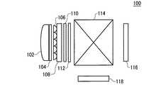
図1は、1つの典型的な高温多結晶シリコン投写型システム100を示す。システム100は、赤色画像、青色画像、および緑色画像、つまり複数の原色画像の生成、または他の複数の光スペクトルに対応する複数の画像を生成する3つの画像生成部を含む。第1の画像生成部は、1つの光源102と、1つの直線偏光子104と、1つのマイクロレンズアレイ106と、1つの液晶パネル108と、1つの補償器110と、1つの検光子112とを含み、1つのカラー画像を生成してこれを1つのXキューブ114に入力する。第2の画像生成部116と第3の画像生成部118とは、詳細には図示されていないが、第1の画像生成部と同様の1つの構造を有し、それぞれ異なる色の複数の画像を生成してXキューブ114に入力する。これら複数の画像生成部によって生成された3色の光はXキューブ114によって組み合わされ、1つの画像生成部が存在しないXキューブ114のポートに配置されている1つの投写レンズ(図示せず)に出力される。 FIG. 1 shows one exemplary high temperature polycrystalline
補償器110はマイクロレンズアレイ106の低F値側にあるが、パネル108の光入力側または光出力側のどちらにでも配置しうる。1つの典型的実施形態においては、投写型システム100は、複数の偏光子104および112としての複数のシート偏光子と、1つのパネル108と、1つの補償器110とを含み、この補償器は、たとえば単一の補償プレートまたは一対の補償プレートにすることができる。マイクロレンズアレイ106は、パネル108の一部にすることができる。マイクロレンズアレイ106をパネル108の一部にする場合、複数の従来型補償プレートを用いてマイクロレンズアレイ106とパネル108との間に1つまたは複数の補償プレートを含めることは難しい。ただし、液晶ポリマー層であれば、薄く、環境堅牢性が高く、製造適合性もあることから、複数の層を容易に組み込みうる。あるいは、一対の補償器110を使用してもよい。一対の補償器110は、パネル108の光入力側と光出力側とに配置することも、パネル108の一方の側だけに配置することも可能である。あるいは、パネル108を形成する複数の基板のうちの1枚を補償器110にすることもできる。このように、パネル108の液晶とマイクロレンズアレイ106との間に補償器を配置しうる。このような一実施形態は、1つの適切な液晶高分子材料から実現しうる。 The
一例として、第1の最小条件が550nmである1つの90°ねじれたネマチック(TN)セルを有する1つのシステムの方位平均コントラストは、所与の1つのF値に対してホメオトロピック加重した緑色光の透過のオンからオフ状態の方位平均比率から計算しうる。赤色光および青色光についても、同様の計算を行いうる。このシステムはZLI4792などの1つの液晶材料を含むが、ZLI4792はメルク社から入手可能であり、表1に示す複数のパラメータを有する1つのネマチック液晶である。この材料の黒色状態の電圧は6Vであり、白色状態の電圧は0Vである。光源は、1つの円錐角が約10度である1つの超高圧(UHP)ランプでもよい。
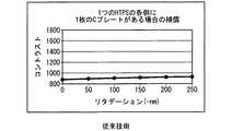
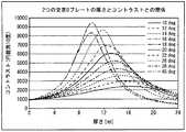
図2は、1つの典型的な光強度分布を示す。光強度の分布は、図2に示す方位対称分布でも、他の適切な分布でもよい。コントラストを計算するには、加重した強度プロファイルによって光錐からの寄与を平均化する。 FIG. 2 shows one typical light intensity distribution. The light intensity distribution may be an azimuthally symmetric distribution shown in FIG. 2 or another appropriate distribution. To calculate contrast, the contribution from the light cone is averaged by a weighted intensity profile.
従来技術のいくつかの補償方式は、黒状態におけるパネル108のダイレクタ分布の方位対称性に依存する。方位対称性への依存は光学軸が1つの垂直成分を有するからであり、これは1つの負のCプレートを使用して補償を行う従来技術の複数の投写型システムにおいて観察されうる。このような一対の負のCプレートを1枚のパネルの各側に直接隣接させて補償を行うと、水平面におけるコントラストが向上する代わりに、±45°の面におけるコントラストが犠牲になる。この結果、漏れが円錐角にわたって平均化されるので、負のCプレートを複数使用して1つの投写型システムの大幅な総合的向上を達成することはできない。 Some prior art compensation schemes rely on azimuthal symmetry of the director distribution of the
図3は、一対の負のCプレートを有する従来技術の1つの投写型システムのコントラストとリタデーションとの関係を示す。この図は、パネルの法線外コントラストは、液晶の複数の残留スプレイ配向側領域近傍では損われるが、ほぼ垂直配向された中心近傍では損われないことを実証している。したがって、1つの奇対称成分を1つの補償器に設けた1つの補償方式を使用すれば、1つのプロジェクタシステムにおけるコントラストの大幅向上を達成しうる。 FIG. 3 shows the relationship between contrast and retardation of one prior art projection system having a pair of negative C plates. This figure demonstrates that the out-of-normal contrast of the panel is impaired in the vicinity of the plurality of residual splay alignment side regions of the liquid crystal, but not in the vicinity of the substantially vertically aligned center. Therefore, if one compensation scheme in which one odd symmetrical component is provided in one compensator is used, a significant improvement in contrast in one projector system can be achieved.
複数のチルト軸を有する複数の補償プレートは、Oプレート補償器と呼ばれる。この特性を有する複数の補償プレートは、複数の「Oプレート」補償器を含む。このような複数のOプレート補償器は、ホモジニアス配向またはスプレイ配向にしてもよく、また正、負、または二軸異方性を有しうる。複数のスプレイ配向Oプレートは、各界面に1つの異なるプレチルト角を設けることによって得られる。あるいは、ツイストなどホモジニアス以外の1つの配向をOプレートに設けてもよい。たとえば、1つのツイスト液晶Oプレート補償器にしてもよい。 A plurality of compensation plates having a plurality of tilt axes are called O-plate compensators. A plurality of compensation plates having this characteristic includes a plurality of “O-plate” compensators. A plurality of such O-plate compensators may be homogeneous or splayed and may have positive, negative, or biaxial anisotropy. Multiple splay alignment O-plates are obtained by providing one different pretilt angle at each interface. Alternatively, one orientation other than homogeneous such as twist may be provided on the O plate. For example, one twist liquid crystal O-plate compensator may be used.
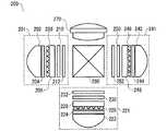
図4は、複数のOプレート補償器を有する、高温多結晶シリコン技術による1つの典型的なツイストネマチック液晶投写型ディスプレイシステム200を示す。システム200は、3つの画像生成部201、221、および241を含む。これらの画像生成部201、221、および241は、赤色画像、青色画像、および緑色画像を生成するように構成されている。画像生成部201は、1つの光源202と1つの直線偏光子204とを含む。光源202は、約10度の1つの円錐角を有する1つの超高圧(UHP)ランプでもよい。画像生成部201は、1つのマイクロレンズアレイ206とこれに隣接する1つの液晶パネル208とをさらに含む。マイクロレンズアレイ206は、液晶パネル208の一部にすることができる。 FIG. 4 shows one exemplary twisted nematic liquid crystal
Oプレート補償器210は液晶パネル208を補償し、液晶パネル208から出力された光は1つの出力検光子212によって検光される。本例においては、Oプレート補償器210はマイクロレンズアレイ206の低F値側にあるが、液晶パネル208の光入力側または光出力側のどちらにでも配置しうる。典型的な一実施形態においては、画像生成部201は、複数の偏光子204および212として複数のシート偏光子を含む。いくつかの実施形態においては、補償器210を単一の補償プレートにすることも、一対の補償プレートにすることもできる。一対の補償プレートを使用して液晶パネル208を補償する場合は、これら複数の補償プレートを液晶パネル208の光入力側と光出力側とに分けて配置することも、液晶パネル208の一方の側だけに配置することもできる。あるいは、パネル208を形成する複数の基板のうちの1枚を補償器210にすることもできる。このように、補償器は、パネル208の液晶とマイクロレンズアレイ206との間に配置しうる。このような1つの実施形態は、1つの適切な液晶高分子材料から実現しうる。 The O-
いくつかの実施形態においては、複数の補償器210、230、および250をそれぞれ正または負の異方性補償器とすることができ、これらの補償器は1つのスプレイ配向を有する複数のネマチック液晶、複数のディスコティック液晶、または他の複数の適切な液晶材料など、1つまたは複数の適切な材料から製造することができる。一般に、1つの液晶パネルの一方の側に直接隣接する補償層は、同じ側にある液晶を補償する。スプレイの面は、一般に、補償器のスプレイと共面をなす。液晶のスプレイと近接補償プレートのスプレイとが共面をなすと、液晶とこれに隣接する1つの補償器とが補償上よく調和するので、パネルの各側に補償器を含む1つの投写型システムを容易に製造できるので都合がよい。この理由は、液晶と補償器とが1つのスプレイ配向構造を有することによる。ただし、いくつかの実施形態においては、複数の正の補償器など、1つの補償器を使用してパネルの反対側のスプレイを補償すると好都合な場合があるが、これは近傍スプレイのリターダンスが1つの偏光要素として機能するからである。 In some embodiments, each of the plurality of
1つのツイスト液晶駆動モードに対して複数の正の一軸プレートを使用する1つの具体的な補償方式を図6に示す。図6の補償方式は、このアプローチの一般的方法論を示すために使用しうる。先ず、このツイスト液晶駆動モードは、1つの上部チルト層と、法線配向された1つの中心層と、1つの第3の下部チルト層とからなる3層の1つの正の複屈折構造として概念的に表すことができる。図6の液晶404の直下に1つの正の二層補償器が示されている。本例においては、この補償器のこれらの層は正の一軸であり、複数の光学軸の各チルト角は一様である。これら複数の正の複屈折補償器層は、1つの三変換方式によって複数の液晶チルト層を補償するために機能する。この補償器の上層および下層は、それぞれ上部および下部の液晶チルト層によって補償される。各液晶チルト層の補償は、チルト層および以降の複数の複屈折層のそれぞれの消偏効果を補正することによって行われる。この方式は、補償を上部および下部の液晶チルト層に分け、光を特定の2つの平面に伝搬させるので都合がよい。これら複数の平面は、液晶セル基板に対して法線をなし、複数のチルト液晶層の複数の光学軸を含む。図6に示す典型的実施形態においては、これら複数の平面は直交する。 FIG. 6 shows one specific compensation method using a plurality of positive uniaxial plates for one twist liquid crystal driving mode. The compensation scheme of FIG. 6 can be used to illustrate the general methodology of this approach. First, this twisted liquid crystal driving mode is conceptually represented as one positive birefringent structure of three layers including one upper tilt layer, one normal-oriented central layer, and one third lower tilt layer. Can be expressed. One positive two-layer compensator is shown directly below the
表2は、1つの光線が1つの平面に法線外の角度で伝搬し、その平面を伝搬する光が下部チルト液晶層の光学軸を含む場合の各層の投影光学軸を示す。
下部補償層の光学軸は、下部偏光子の軸に並行しているので透過強度を損わないため、無視できる。中心および下部の液晶層はそれぞれ同じ光学軸を有するので、単一の正のリターダと見なすことができる。 Since the optical axis of the lower compensation layer is parallel to the axis of the lower polarizer, the transmission intensity is not impaired and can be ignored. Since the central and lower liquid crystal layers each have the same optical axis, they can be regarded as a single positive retarder.
したがって、上部補償層は、第1のチルトリターダの消偏と、その光学軸が伝搬方向によって規定される次の第2のリターダの消偏とを1つの第3の偏光変換によって補正するように機能する。上層の光学軸の角度と中心層のリターダンス値とは、どちらもこの平面における伝搬角度にほぼ比例する。所望の補償の角度依存性に応じたチルト角を有する1つの補償器が必要とされる。誘発された正味偏光を解消するには、この補償器のチルト角は、補償される上部液晶チルト層の角度の逆にする必要がある。チルト角およびリターダンスのそれぞれの精確な値は駆動される液晶の複数のパラメータに応じて異なるが、配向角の符号はこの正味三変換方式によって決まる。 Therefore, the upper compensation layer corrects the depolarization of the first tilt retarder and the depolarization of the next second retarder whose optical axis is defined by the propagation direction by one third polarization conversion. Function. Both the angle of the optical axis of the upper layer and the retardance value of the central layer are approximately proportional to the propagation angle in this plane. One compensator is needed with a tilt angle that depends on the desired angular dependence of compensation. To eliminate the induced net polarization, the tilt angle of this compensator needs to be the inverse of the angle of the upper liquid crystal tilt layer to be compensated. The exact values of the tilt angle and the retardance differ depending on a plurality of parameters of the liquid crystal to be driven, but the sign of the orientation angle is determined by this net three conversion method.
表3は、1つの光線が1つの平面に法線外角度で伝搬し、その平面を伝搬する光が上部チルト液晶層の光学軸を含む場合の各層の投影光学軸を示す。
上部および中心の補償層の光学軸は、上部偏光子の軸に並行であるので透過強度を損わないため、無視できる。The optical axes of the upper and central compensation layers are negligible because they are parallel to the axis of the upper polarizer and do not impair the transmission intensity.
したがって、下部補償層は、上部液晶層に対応付けられた1つのチルトリターダの消偏と、伝搬方向によってその光学軸が規定される上部補償層に対応付けられた1つのリターダの消偏とを補正するように機能する。この場合もまた、上層の光学軸の角度は伝搬角度に依存するので、1つのチルト補償器のチルト角は、補償対象の下部液晶チルト層のチルト角とは逆にする必要がある。伝搬面ごとに最適化を行うことによって、複数のツイストネマチックモードに対して有効な正の複屈折斜め配向プレートによる1つの補償方式を実現することができる。この補償方式は、回転角度が90度の複数の偏光軸に対しても有効である。このアプローチのさらなる改良版では、上記2つのシナリオにおいて複数の偏光軸に投影されるリタデーションを加減するために、負または正の複数のCプレート(すなわち、複数の光学軸が液晶基板に対して法線をなす複数の複屈折層)を用いることができるであろう。 Therefore, the lower compensation layer has the depolarization of one tilt retarder associated with the upper liquid crystal layer and the depolarization of one retarder associated with the upper compensation layer whose optical axis is defined by the propagation direction. Function to correct. Also in this case, since the angle of the optical axis of the upper layer depends on the propagation angle, the tilt angle of one tilt compensator needs to be opposite to the tilt angle of the lower liquid crystal tilt layer to be compensated. By performing optimization for each propagation plane, it is possible to realize one compensation method using a positive birefringent oblique alignment plate effective for a plurality of twisted nematic modes. This compensation method is also effective for a plurality of polarization axes with a rotation angle of 90 degrees. In a further refinement of this approach, multiple negative or positive C plates (ie, multiple optical axes are modulo relative to the liquid crystal substrate) to moderate the retardation projected onto multiple polarization axes in the above two scenarios. A plurality of birefringent layers forming a line) could be used.
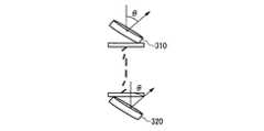
図5Aは、図4のシステム400など、1つの高温多結晶シリコンのツイストネマチック液晶投写型ディスプレイシステムの補償に2つの負のOプレート310および320を使用した1つの典型的構成を示す。複数の負のOプレート310および320は1つのチルト角θを有し、この2つの負のOプレートのチルト軸は互に直交する。液晶は90°ねじれた1つのネマチック構造を有し、基板・液晶境界に隣接する液晶の平均光学軸は、隣接するOプレートの平均光学軸にほぼ並行である。 FIG. 5A shows one exemplary configuration using two negative O-
図5Bは、2つの負のOプレートを有する1つの投写型システムのコントラストとチルト角との間の関係を示す。これらのOプレートの厚さ値は、それぞれ18、20、22、および24ミクロンである。図5は、さまざまな厚さとチルト角に対して超ハイコントラストを達成できることを実証している。 FIG. 5B shows the relationship between contrast and tilt angle for one projection system with two negative O-plates. The thickness values of these O plates are 18, 20, 22, and 24 microns, respectively. FIG. 5 demonstrates that ultra-high contrast can be achieved for various thicknesses and tilt angles.
図6は、一対の正のOプレートを含む、1つのプロジェクタシステムのための1つの典型的な補償方式である。システム400は、1つのツイストネマチック液晶パネル404と、これに隣接する45°に配向された1つの偏光子402とを含む。1つの第1の正のOプレート406は1つの配向θ=45°を有し、1つの第2の正のOプレート408は1つの配向θ=135°を有し、1つの偏光子410は135°に配向されている。ツイストネマチック液晶パネル404は、1つの左旋回ツイストを有する。あるいは、2つの正のOプレートのチルト角をそれぞれ違えることもできる。 FIG. 6 is one exemplary compensation scheme for a projector system that includes a pair of positive O-plates.
2つのOプレートのチルト角がそれぞれ異なるこの典型的実施形態の一例は、1つの左旋回ツイストを有する市販のツイストネマチックセルから作成した1つのツイストネマチック液晶パネルを含み、1つの第1の正のOプレート406は1つの配向30°と、1つのΔn=0.008と、1つのd=11.5μmとを有し、1つの第2の正のOプレート408は1つの配向24°と、1つのΔn=0.008と、1つのd=14μmとを有する。偏光子402は45°に配向されており、偏光子410は135°に配向されている。このシステムの1つのコントラストは、液晶および補償器のそれぞれの複屈折プロファイルによる消偏効果がない状態で、11,000:1を超える。 An example of this exemplary embodiment in which the tilt angles of the two O-plates are different includes one twisted nematic liquid crystal panel made from a commercially available twisted nematic cell with one left turn twist, one first positive The
2つのスプレイOプレートのチルト角がそれぞれ異なるこの典型的実施形態の一例は、1つの左旋回ツイストを有する市販のツイストネマチックセルから作成した1つのツイストネマチック液晶パネルを含み、1つの第1の正のスプレイOプレート406は1つの配向0°,45°と、1つのon軸リタデーションΓ(on軸)=55nmとを有し、1つの第2の正のOプレート408は1つの配向0°,−32°と、1つのon軸リタデーションΓ(on軸)=72nmとを有する。偏光子402は45°に配向されており、偏光子410は135°に配向されている。このシステムの1つのコントラストは、液晶および補償器のそれぞれの複屈折プロファイルによる消偏効果がない状態で60,000:1を超えるが、その理由は、1つのスプレイセルの可変構造が、チルト角が固定された1つのホモジニアス補償器の構造より、ツイストネマチック液晶の構造に近いからである。さらに、スプレイ構造によってコントラストが十分に向上するので、この補償方式は、複数の投写型システム以外の装置、たとえば複数のフラットパネル液晶ディスプレイなどにも適用することができる。 An example of this exemplary embodiment in which the two spray O-plates have different tilt angles includes one twisted nematic liquid crystal panel made from a commercially available twisted nematic cell with one left-turning twist. The spray O-
本発明の別の典型的実施形態によると、1つの第1の補償器を使用して第1の液晶スプレイを補償し、側面の1つの第2の補償器によって第2の液晶スプレイを補償することによって、1つの二面補償方式の対称性が破られる。スプレイ用に単一層モデルを使用する場合は、ツイストネマチック液晶ディスプレイの入力スプレイに直角な平面における入力光線を考慮する。ツイストネマチックのスプレイは、1つの反時計回りのリターダとして現れる。これに続くのが固有方向に沿った1つのリターダであり、これはセルのZリターダンスとツイストネマチック液晶ディスプレイの出力スプレイとの組み合わせによって形成される。偏光の補正は、1つの時計回りのリターダを表す第1の補償器によって行われる。第2の補償器は、固有方向に沿った1つのリタデーションを与えるが、これは偏光状態には影響しない。この平面については、補償は上記と同程度である。 According to another exemplary embodiment of the present invention, one first compensator is used to compensate the first liquid crystal spray, and one lateral compensator is used to compensate the second liquid crystal spray. This breaks the symmetry of one two-plane compensation scheme. When using a single layer model for spraying, consider input rays in a plane perpendicular to the input spray of the twisted nematic liquid crystal display. A twisted nematic spray appears as one counterclockwise retarder. Following this is a retarder along the eigen direction, which is formed by a combination of the Z retardance of the cell and the output spray of the twisted nematic liquid crystal display. Polarization correction is performed by a first compensator representing one clockwise retarder. The second compensator gives one retardation along the natural direction, but this does not affect the polarization state. For this plane, the compensation is similar to the above.
1つの光線がツイストネマチック入力スプレイの平面に入射する場合は、この状況が変化する。ここで、セルのZリターダンスとツイストスプレイとからなる固有配向リターダに最初に遭遇するが、このリターダは偏光状態に何も影響を及ぼさない。次に、1つの反時計回りのリターダを表す、液晶ディスプレイの第2の表面でのスプレイアップが続く。このとき、第1の補償器は、固有方向に沿った1つのリターダを表す。この次に、時計回りのリターダを表す第2の補償器によるスプレイダウンが続く。この平面において、両方の補償器が3つの偏光変換に関与する。 This situation changes if a ray is incident on the plane of the twisted nematic input spray. Here we first encounter an intrinsic orientation retarder consisting of the cell's Z retardance and twist spray, but this retarder has no effect on the polarization state. This is followed by a spray-up on the second surface of the liquid crystal display, representing one counterclockwise retarder. At this time, the first compensator represents one retarder along the eigen direction. This is followed by spraydown with a second compensator representing a clockwise retarder. In this plane, both compensators are responsible for the three polarization conversions.
本発明による補償器によって総合的なコントラストを最適化するには、液晶ディスプレイの具体的な複数のパラメータを考慮して、複数の補償器のリタデーションおよび複数のスプレイパラメータ(各表面のプレチルト)をそれぞれ独立に選択する必要がある。入力ツイストネマチックスプレイに直交する平面においては、第1の補償器(液晶に隣接する補償器)の複数のパラメータだけが関係する。したがって、この平面は、第1の補償器に対する複数の基準を確立するために使用しうる。次に、コントラスト輪郭を最大化し、ハイコントラストの角度カバレージを法線入射角方向に沿って広げるために、第2の補償器に対する調整を中心近くで使用してもよい。この方法は、補償器パラメータの選択によってハイコントラストを生み出す効率的な方法の1つである。このように、1つまたは複数の層を追加挿入することによって、性能をさらに最適化することができる。たとえば、第1の補償器と第2の補償器との間に、1つの特定量のZリタデーションを挿入することができる。 In order to optimize the overall contrast with the compensator according to the present invention, considering the specific parameters of the liquid crystal display, the retardation of the compensators and the splay parameters (pretilt of each surface) respectively. Must be selected independently. In the plane orthogonal to the input twist nematics spray, only the parameters of the first compensator (compensator adjacent to the liquid crystal) are relevant. This plane can therefore be used to establish multiple criteria for the first compensator. Adjustments to the second compensator may then be used near the center to maximize the contrast profile and broaden the high contrast angular coverage along the normal incidence angle direction. This method is one of the efficient ways to produce high contrast by selecting compensator parameters. In this way, performance can be further optimized by additional insertion of one or more layers. For example, one specific amount of Z retardation can be inserted between the first compensator and the second compensator.
図7は、2つの正のOプレートを使用して補償した場合のコントラストと厚さとの関係を示す。記載の複数の実施形態においては、これらのOプレートの厚さは、約8umから約15umであり、最適設計での厚さは通常10umから12umである。これらのOプレートのチルト角を10°から50°の1つの範囲にしてもよく、最適設計における1つのチルト角範囲は通常20°から40°であり、複屈折はΔn=0.008である。 FIG. 7 shows the relationship between contrast and thickness when compensated using two positive O-plates. In the described embodiments, the thickness of these O-plates is from about 8 um to about 15 um, and the optimum design thickness is typically 10 um to 12 um. The tilt angle of these O-plates may be in a range of 10 ° to 50 °, one tilt angle range in the optimum design is usually 20 ° to 40 °, and birefringence is Δn = 0.008. .
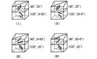
図8は、チルト角が一様な1つの補償プレートとスプレイ配向の1つの補償プレートとを含む4つの可能な構成を示す。コントラストは、構成Iでは5600:1、構成IIでは8200:1、構成IIIでは8800:1、構成IVでは6500:1である。最上部のプレートは45°に配向されており、最下部のプレートは135°に配向されている。チルト配向プレートのチルト角は25°であり、スプレイ配向プレートは0°から50°または50°から0°の1つのチルト範囲を有する。これらのプレートの厚さは12umであり、デルタ(n)=0.008である。これらのプレートのそれぞれの配向を45°および135°以外にしてもよい。たとえば、これらのプレートのそれぞれの配向を直交する2つの任意の配向角度にしてもよい。これらのスプレイプレートのチルト角は0°または50°のどちらにしてもよく、また50°以外の角度にしてもよい。 FIG. 8 shows four possible configurations including one compensation plate with uniform tilt angle and one compensation plate with splay orientation. Contrast is 5600: 1 for Configuration I, 8200: 1 for Configuration II, 8800: 1 for Configuration III, and 6500: 1 for Configuration IV. The top plate is oriented at 45 ° and the bottom plate is oriented at 135 °. The tilt angle of the tilt alignment plate is 25 °, and the spray alignment plate has one tilt range of 0 ° to 50 ° or 50 ° to 0 °. The thickness of these plates is 12 um and delta (n) = 0.008. The orientation of each of these plates may be other than 45 ° and 135 °. For example, the orientation of each of these plates may be two arbitrary orientation angles orthogonal to each other. The tilt angle of these spray plates may be 0 ° or 50 °, or may be an angle other than 50 °.
図9は、1つの第1の補償プレート(45°,0〜50°)と1つの第2の補償プレート(135°,50〜0°)とを備え、9000:1を超える1つのコントラストを有する1つの二重スプレイ配向補償方式を示す。これらのプレートのそれぞれの配向は、45°および135°以外でもよい。たとえば、これらのプレートのそれぞれの配向を直交する2つの任意の配向角度にしてもよい。これらのスプレイプレートのチルト角を0°または50°のどちらにしてもよく、また50°以外の1つの角度差を持たせてもよい。さらに、これら2つのスプレイプレートのスプレイを同様または同一にすることも、非対称スプレイまたはそれぞれ異なるスプレイにしてもよい。 FIG. 9 comprises one first compensation plate (45 °, 0-50 °) and one second compensation plate (135 °, 50-0 °), with one contrast exceeding 9000: 1. 1 shows one double splay alignment compensation scheme. The orientation of each of these plates may be other than 45 ° and 135 °. For example, the orientation of each of these plates may be two arbitrary orientation angles orthogonal to each other. The tilt angle of these spray plates may be either 0 ° or 50 °, and may have one angle difference other than 50 °. Furthermore, the sprays of these two spray plates may be the same or the same, or may be asymmetric sprays or different sprays.
図10は、2つのスプレイ配向Oプレートによる補償がある場合とない場合の、1つのHTPSの視野を示す。 FIG. 10 shows the field of view of one HTPS with and without compensation by two splay orientation O-plates.
複数のリターダ膜を生成するための複数の技術として、複数の延伸高分子膜、複数の研磨無機結晶、複数の斜方蒸着またはパターン化膜、複数の液晶、および複数の高分子液晶などが挙げられる。いくつかの方法は、他の複数の方法より、いくつかの用途に適していることもある。たとえば、複数の延伸リターダは、最良ケースの標準偏差が±2nmである複数の100nm超のリターダンスに適している。ただし、複数の延伸リターダは複数の超低リタデーション値での制御が難しく、またキャスティング工程の故に複数の審美的要件を満たしにくい場合がある。実際に、機械的に信頼性が高く、熱負荷の存在下で光学的によく機能し、総合的な透過波面ひずみの発生が低い1つの方法で、複数の延伸リターダ膜を搭載することは難しい場合がある。さらに、複数の延伸方法は光学軸の斜め配向を複数生成しないこともあり、結果として低歩留まりおよびコスト増をもたらしうる。 Multiple techniques for generating multiple retarder films include multiple stretched polymer films, multiple polished inorganic crystals, multiple oblique deposition or patterned films, multiple liquid crystals, and multiple polymer liquid crystals. It is done. Some methods may be more suitable for some applications than other methods. For example, a plurality of stretched retarders are suitable for a plurality of retardances greater than 100 nm with a best case standard deviation of ± 2 nm. However, it is difficult to control a plurality of stretched retarders with a plurality of ultra-low retardation values, and it may be difficult to satisfy a plurality of aesthetic requirements due to the casting process. In fact, it is difficult to mount multiple stretched retarder films in one way that is mechanically reliable, functions optically in the presence of thermal loads, and has low overall transmitted wavefront distortion. There is a case. Furthermore, multiple stretching methods may not produce multiple oblique orientations of the optic axis, which can result in low yields and increased costs.
別の例は、複数の無機リターダである。原材料の適切な鋸引きとその後の1回の研磨処理とによって斜め光学軸配向を有する無機リターダを製造しうる。水晶など、複数の材料については、研磨による複数のゼロオーダの半波長リターダンスは実証されている。複数の無機リターダは、その光学的品質および光強度の処理能力の高さ故に、好都合である。 Another example is a plurality of inorganic retarders. An inorganic retarder having an oblique optical axis orientation can be produced by appropriate sawing of the raw material followed by a single polishing process. For multiple materials, such as quartz, multiple zero-order half-wave retardances due to polishing have been demonstrated. Multiple inorganic retarders are advantageous because of their high optical quality and high light intensity throughput.
複数の液晶高分子膜は、上記の複数の基準をすべて満たす可能性を有する。各界面のプレチルト角を制御することによって、スプレイ配向膜およびホモジニアス配向膜の両方を製造することができる。多層膜の場合は、可能な複数の補償構造の種類が限定されない。たとえば、正の誘電異方性を有する複数のネマチック高分子液晶は入手しやすく、1つの流体状態にあるときに、非高分子液晶と同様の物理学を用いて配向しうる。別の例は、1つのマイクロアレイと液晶パネルとの間に1つの補償構造を配置する方式である。この高分子補償構造は、薄く、堅牢で(たとえば、複数の高輝度ランプで使用しうる)、既存の複数の製造技術に対応するものでなければならない。赤外線(UV)光または別の適切な手法を用いてこれら複数の高分子液晶を架橋することによって、1つの固体薄膜を形成する。これら複数の手法を用いて、大小のプレチルト角を基板界面および空気界面の両方または一方に複数作成しうる。従来の複数の被覆方法を使用してこのような複数の薄い補償膜を単一の基板に蒸着してもよく、または従来の製造方法で積層ガラスセルを製造してから、UV架橋によって複数の補償プレートを製造してもよい。 The plurality of liquid crystal polymer films have a possibility of satisfying all of the above plurality of criteria. By controlling the pretilt angle of each interface, both the splay alignment film and the homogeneous alignment film can be manufactured. In the case of a multilayer film, the types of possible compensation structures are not limited. For example, a plurality of nematic polymer liquid crystals having positive dielectric anisotropy are readily available and can be aligned using the same physics as non-polymer liquid crystals when in one fluid state. Another example is a system in which one compensation structure is arranged between one microarray and a liquid crystal panel. The polymer compensation structure must be thin, robust (e.g., usable with multiple high intensity lamps) and compatible with existing manufacturing technologies. One solid thin film is formed by crosslinking the plurality of polymeric liquid crystals using infrared (UV) light or another suitable technique. Using these plural methods, a plurality of large and small pretilt angles can be created at both or one of the substrate interface and the air interface. A plurality of such thin compensation films may be deposited on a single substrate using conventional coating methods, or a laminated glass cell is manufactured by conventional manufacturing methods, and then a plurality of by UV crosslinking. Compensation plates may be manufactured.
複数のダイレクタ分布が十分に制御され、高精度のリタデーションを有する複数の補償膜が製造されれば、複数の補償方式を容易に再現でき、性能の信頼性が高まる。たとえば、複数の液晶高分子層を使用すれば、他の複数の材料では容易に作成できなかった複数の低リターダンス膜を作成しうる。 If a plurality of compensation films having sufficiently controlled retardation distribution and high-precision retardation are manufactured, a plurality of compensation methods can be easily reproduced, and reliability of performance is improved. For example, if a plurality of liquid crystal polymer layers are used, a plurality of low retardance films that could not be easily formed using other materials can be formed.
好都合な複数のリターダ膜材料は、以下の複数の特性の多くを含むことが多い。
リタデーションの正確な再現性および一様性、
面内光学軸の再現性および一様性の超高精度制御、
再現可能で一様な1つの適切な面外光学軸プロファイルの生成可能性、
低リターダンス値(たとえば、25〜200nm)の複数の膜の製造の実行可能性、
低消偏度(たとえば、ヘイズ)、
高輝度下での耐久性(および、場合によっては、いくらかの耐紫外線性)、
温度変動時の性能信頼性、
審美的欠陥が少ない仕様(特にLCD平面において)、
光学性能に対する実装工程の不感性、および
実装工程の信頼性(層間はく離)。
どの材料が最適であるかは、投写型システムの意図する用途または複数の要件に応じて異なることもある。Convenient retarder membrane materials often include many of the following properties:
Accurate reproducibility and uniformity of retardation,
Ultra-high precision control of reproducibility and uniformity of in-plane optical axes,
The possibility of generating one suitable out-of-plane optical axis profile that is reproducible and uniform,
Feasibility of manufacturing multiple films with low retardance values (eg, 25-200 nm),
Low bias (for example, haze),
Durability under high brightness (and possibly some UV resistance),
Performance reliability during temperature fluctuations,
Specifications with few aesthetic defects (especially on LCD planes),
Mounting process insensitivity to optical performance, and mounting process reliability (delamination).
Which material is optimal may depend on the intended use or requirements of the projection system.
別の代替補償方式として、1つの補償器を光源偏光子とマイクロレンズアレイとの間に配置する方式が挙げられる。このような1つの補償器のチルト角およびリターダンスは、マイクロレンズアレイのパワーに応じて調整されることになる。 Another alternative compensation method is a method in which one compensator is disposed between the light source polarizer and the microlens array. The tilt angle and retardance of such a compensator are adjusted according to the power of the microlens array.
本発明の複数の実施形態および複数の利点を詳述してきたが、本発明の教示内容および複数の添付請求項によって規定される本発明の精神および範囲から逸脱することなく複数の変更、複数の置換、複数の変形、複数の修正、複数の変体、複数の並べ換え、および複数の改造を行いうることを理解されるべきである。 Although embodiments and advantages of the present invention have been described in detail, modifications, changes and modifications may be made without departing from the spirit and scope of the invention as defined by the teachings of the invention and the appended claims. It should be understood that substitutions, multiple variations, multiple modifications, multiple variations, multiple permutations, and multiple modifications may be made.
本発明による複数の実現方法を複数の具体的実施形態のコンテキストにおいて説明した。これら複数の実施形態は説明を目的としたものであり、制限を目的としたものではない。多くの変体、修正、追加、および改良が可能である。したがって、本願明細書では単一の具体例で説明されている複数の構成要素に対して複数の具体例がありうる。さまざまな構成要素、さまざまな操作、およびさまざまなデータストアのそれぞれの間の複数の境界はある程度自由に決められるものであり、複数の特定の操作は特定の説明のための複数の構成の下で示されている。他の複数の機能割り当てが想定され、これらは以下の特許請求の範囲に含まれうる。最後に、これら複数の典型的構成において複数の個別構成要素として提示されている複数の構造および機能は、1つの組み合わされた構造または構成要素としても実装しうる。上記および他の複数の変体、複数の修正、複数の追加、および複数の改良は、以下の特許請求の範囲に定義されている本発明の範囲に含まれうる。 Several implementations according to the invention have been described in the context of several specific embodiments. These embodiments are for illustrative purposes and are not intended to be limiting. Many variations, modifications, additions, and improvements are possible. Accordingly, there may be a plurality of specific examples for a plurality of components described in the present specification as a single specific example. The various components, the various operations, and the multiple boundaries between each of the various data stores can be freely determined to some extent, and the multiple specific operations are under multiple configurations for a specific description. It is shown. Other multiple function assignments are envisioned and can be included in the scope of the following claims. Finally, the structures and functions presented as the individual components in these exemplary configurations may also be implemented as a combined structure or component. These and other variations, modifications, additions, and improvements may be included within the scope of the invention as defined in the following claims.
本願明細書の各節の見出しは、37CFR1.77に示唆されている1つの出願を構成する複数の部分との一貫性を保つために、あるいは構成上の複数の手掛かりを与えるために設けられているものである。これら複数の見出しは、本願から生じうるあらゆる特許申請に示される1つまたは複数の発明を制限するものでも特徴付けるものでもない。具体的に一例を挙げれば、これら複数の見出しは1つの「発明の分野」に言及しているが、この見出しの下でいわゆる発明の分野を説明するために選択された言語によって特許請求の範囲が制限されてはならない。さらに、「関連技術の説明」における1つの技術の1つの説明は、その技術が本願の先行技術であることを認めているものと解釈されてはならない。「発明の概要」もまた、本願の特許請求の範囲に示されている1つまたは複数の発明の1つの特徴付けと見なされるべきではない。さらに、これら複数の見出しにおいて「発明」が単数形で言及されていても、本願に主張されている新規点が1つだけであるとの主張に使われるべきではない。この特許明細書に対応付けられている複数の請求項の複数の制限に従って複数の発明を規定しうるので、したがって1つまたは複数の発明はこれら複数の請求項によって定義され、かつ保護される。あらゆる場合において、複数の請求項の範囲は、本明細書に照らしてそれ自体の価値によって考慮されるべきであり、本願明細書に含まれている複数の見出しによって制約されるべきではない。 The section headings in this specification are provided to maintain consistency with the parts that make up one application suggested in 37CFR 1.77, or to provide structural clues. It is what. These headings are not intended to limit or characterize the invention or inventions presented in any patent application that may arise from this application. Specifically, by way of example, these headings refer to one “field of invention”, but under this heading the claims in the language chosen to describe the so-called field of invention Should not be restricted. Further, one description of one technique in the “Description of Related Techniques” should not be construed as an admission that the technique is prior art to the present application. Neither is the "Summary" to be considered as a characterization of one or more inventions set forth in the claims hereof. Furthermore, even though “invention” is referred to in the singular form in these multiple headings, it should not be used to claim that there is only one novelty point claimed in this application. Since multiple inventions may be defined in accordance with the limitations of the multiple claims associated with this patent specification, one or more inventions are thus defined and protected by these multiple claims. In all cases, the scope of the claims should be considered according to their own values in light of the specification and should not be limited by the headings contained herein.
100 高温多結晶シリコン投写型システム
102 光源
104 直線偏光子
106 マイクロレンズアレイ
108 液晶パネル
110 補償器
112 検光子
114 Xキューブ
116 第2の画像生成部
118 画像生成部100 high-temperature polycrystalline
Claims (84)
Translated fromJapanese1つの第1のパネルと、
前記第1のパネルに隣接する1つの第1の光源と、
前記第1のパネルに結合された1つの導光要素と、
前記第1のパネルに隣接する1つの第1の斜め配向異方性補償要素と、を含み、前記第1の斜め配向異方性補償要素が法線外入射光の1つの偏光状態を変えるように構成されている投写型システム。A projection system,
One first panel;
A first light source adjacent to the first panel;
One light guide element coupled to the first panel;
A first oblique orientation anisotropy compensation element adjacent to the first panel, wherein the first oblique orientation anisotropy compensation element changes one polarization state of off-normal incident light. Projection type system configured in
1つの第1のパネルと、
前記第1のパネルに結合された1つの第1の光源と、
前記第1のパネルに結合された1つの導光要素と、
前記第1のパネルに隣接し、法線外入射光の1つの偏光状態を変えるように構成されている1つの第1の斜め配向補償要素と、
1つの第2の斜め配向補償要素と、
前記第2の斜め配向補償要素に隣接する1つの第2のパネルと、
前記第2のパネルに結合された1つの第2の光源と、
1つの第3の斜め配向補償要素と、
前記第3の斜め配向補償要素に隣接する1つの第3のパネルと、
前記第3のパネルに結合された1つの第3の光源と、を含み、前記第1、第2、および第3の斜め配向補償要素が法線外入射光の1つの偏光状態を変えるように構成され、前記導光要素が前記第1、第2、および第3のパネルによって変調された光を組み合わせて1つの画像を形成するように構成されている投写型システム。A projection system,
One first panel;
A first light source coupled to the first panel;
One light guide element coupled to the first panel;
A first oblique alignment compensation element adjacent to the first panel and configured to change one polarization state of off-normal incident light;
One second oblique alignment compensation element;
A second panel adjacent to the second oblique orientation compensation element;
A second light source coupled to the second panel;
One third oblique alignment compensation element;
A third panel adjacent to the third oblique orientation compensation element;
A third light source coupled to the third panel, wherein the first, second, and third oblique orientation compensation elements change one polarization state of off-normal incident light A projection system configured, wherein the light guide element is configured to combine the light modulated by the first, second, and third panels to form an image.
前記第1のパネルに隣接する1つの第4の斜め配向補償要素と、
前記第2のパネルに隣接する1つの第5の斜め配向補償要素と、
前記第3のパネルに隣接する1つの第6の斜め配向補償要素と、をさらに含む投写型システム。28. A projection system according to claim 27, comprising:
A fourth oblique alignment compensation element adjacent to the first panel;
One fifth oblique alignment compensation element adjacent to the second panel;
A projection system further comprising a sixth oblique alignment compensation element adjacent to the third panel;
1つの第1のスプレイチルトプロファイルを有する1つの第1の斜めスプレイ配向補償要素と、
1つの第2のスプレイチルトプロファイルを有する1つの第2の斜めスプレイ配向補償要素と、
前記第1および第2の斜めスプレイ配向補償要素に隣接する1つの液晶パネルと、を含み、前記第1のスプレイチルトプロファイルが前記第2のスプレイチルトプロファイルとは異なり、前記複数の斜めスプレイ配向補償要素が法線外入射光の1つの偏光状態を変えるように構成されている液晶投写デバイス。A liquid crystal projection device,
One first oblique splay orientation compensation element having one first splay tilt profile;
One second oblique splay orientation compensation element having one second splay tilt profile;
A liquid crystal panel adjacent to the first and second oblique splay alignment compensation elements, wherein the first splay tilt profile is different from the second splay tilt profile, and the plurality of oblique splay alignment compensations A liquid crystal projection device in which the element is configured to change one polarization state of off-normal incident light.
1つの第1の斜め配向異方性補償要素によって少なくとも1つのパネルを補償するステップと、
前記少なくとも1つのパネルを1つの第2の斜め配向異方性補償要素によって補償するステップと、
前記少なくとも1つのパネルによって変調された光を用いて少なくとも1つの導光要素によって1つの画像を形成するステップと、を含み、前記第1および第2の斜め配向異方性補償要素が法線外入射光の1つの偏光状態を変えるように構成されており、前記第1および第2の斜め配向異方性補償要素が最大方位平均コントラストにほぼ最適化されている方法。A method for compensating a projection system,
Compensating at least one panel with one first oblique orientation anisotropy compensation element;
Compensating the at least one panel with one second oblique orientation anisotropy compensation element;
Forming an image with at least one light guide element using light modulated by the at least one panel, wherein the first and second oblique orientation anisotropy compensation elements are out of normal A method configured to change one polarization state of incident light, wherein the first and second oblique orientation anisotropy compensation elements are substantially optimized for maximum azimuth average contrast.
1つのパネルと、
前記パネルの1つの第1の側に光学的に配置された1つの第1の斜め配向異方性補償要素と、
前記第1の斜め配向異方性補償要素と前記パネルの前記第1の側との間に配置された1つの第2の斜め配向異方性補償要素と、を含み、前記第1の斜め配向異方性補償要素が、前記パネルの前記第1の側に隣接する、前記パネルの1つの第1の平面部分の前記平均チルト角に対して1つの平均チルト角を有し、また前記第2の斜め配向異方性補償要素が、前記パネルの前記第2の側に隣接する、前記パネルの1つの第2の平面部分の平均チルト角に対して1つの平均チルト角を有する投写型システム。A projection system,
One panel,
One first oblique orientation anisotropy compensation element optically disposed on one first side of the panel;
A first oblique orientation anisotropy compensation element disposed between the first oblique orientation anisotropy compensation element and the first side of the panel, wherein the first oblique orientation The anisotropy compensation element has an average tilt angle relative to the average tilt angle of one first planar portion of the panel adjacent to the first side of the panel, and the second Wherein the oblique orientation anisotropy compensation element has an average tilt angle relative to an average tilt angle of one second planar portion of the panel adjacent to the second side of the panel.
1つの第1のパネルと、
前記第1のパネルに隣接する1つの第1の光源と、
前記第1のパネルに結合された1つの導光要素と、
前記第1のパネルに隣接する1つの第1の斜め配向異方性補償要素と、を含み、前記第1の斜め配向異方性補償要素が法線外入射光の1つの偏光状態を変えるように構成され、前記第1の斜め配向補償要素の前記異方性が正の異方性である投写型システム。A projection system,
One first panel;
A first light source adjacent to the first panel;
One light guide element coupled to the first panel;
A first oblique orientation anisotropy compensation element adjacent to the first panel, wherein the first oblique orientation anisotropy compensation element changes one polarization state of off-normal incident light. A projection type system, wherein the anisotropy of the first oblique alignment compensation element is positive anisotropy.
Applications Claiming Priority (2)
| Application Number | Priority Date | Filing Date | Title |
|---|---|---|---|
| US42243702P | 2002-10-30 | 2002-10-30 | |
| PCT/US2003/034615WO2004042469A2 (en) | 2002-10-30 | 2003-10-30 | Oblique plate compensators for projection display systems |
Publications (2)
| Publication Number | Publication Date |
|---|---|
| JP2006505014Atrue JP2006505014A (en) | 2006-02-09 |
| JP2006505014A5 JP2006505014A5 (en) | 2009-12-03 |
Family
ID=32312505
Family Applications (1)
| Application Number | Title | Priority Date | Filing Date |
|---|---|---|---|
| JP2004550302APendingJP2006505014A (en) | 2002-10-30 | 2003-10-30 | Multiple obliquely oriented plate compensators for multiple projection display systems |
Country Status (5)
| Country | Link |
|---|---|
| US (1) | US7126649B2 (en) |
| EP (1) | EP1556732A4 (en) |
| JP (1) | JP2006505014A (en) |
| AU (1) | AU2003290555A1 (en) |
| WO (1) | WO2004042469A2 (en) |
Cited By (5)
| Publication number | Priority date | Publication date | Assignee | Title |
|---|---|---|---|---|
| JP2008077075A (en)* | 2006-08-23 | 2008-04-03 | Jds Uniphase Corp | Cartesian polarizer using photo-aligned liquid crystal |
| JP2009075459A (en)* | 2007-09-21 | 2009-04-09 | Fujifilm Corp | Biaxial birefringent manufacturing method, biaxial birefringent body, and liquid crystal projector |
| JPWO2008078764A1 (en)* | 2006-12-27 | 2010-04-30 | 富士フイルム株式会社 | Phase difference compensation element, VAN liquid crystal display element, and liquid crystal projector |
| US8294836B2 (en) | 2007-12-06 | 2012-10-23 | Seiko Epson Corporation | Liquid crystal display device and projector |
| JP2018533040A (en)* | 2015-10-05 | 2018-11-08 | エルジー・ケム・リミテッド | Optical film |
Families Citing this family (18)
| Publication number | Priority date | Publication date | Assignee | Title |
|---|---|---|---|---|
| DE60336184D1 (en)* | 2002-02-06 | 2011-04-14 | Merck Patent Gmbh | Birefringent film and its use |
| JP2006011298A (en)* | 2004-06-29 | 2006-01-12 | Sony Corp | Liquid crystal projector system |
| JP2006078637A (en)* | 2004-09-08 | 2006-03-23 | Seiko Epson Corp | Liquid crystal device and projection display device |
| JP4192878B2 (en)* | 2004-09-29 | 2008-12-10 | セイコーエプソン株式会社 | Projection display |
| JP2006145566A (en)* | 2004-11-16 | 2006-06-08 | Nec Lcd Technologies Ltd | Liquid crystal display |
| JP2007017485A (en)* | 2005-07-05 | 2007-01-25 | Fujifilm Holdings Corp | Liquid crystal display device and liquid crystal projector |
| JP2008176168A (en)* | 2007-01-22 | 2008-07-31 | Seiko Epson Corp | Liquid crystal device and projector provided with the same |
| EP1956425A3 (en)* | 2007-02-09 | 2009-04-29 | JDS Uniphase Corporation | Single-layer birefringent crystal optical retarders |
| TWI364564B (en)* | 2007-05-04 | 2012-05-21 | Ind Tech Res Inst | Low color shift polarizer film assembly, lcd, low color shift polarized light source and method for polarization translation and color shift compensation |
| JP4479846B2 (en)* | 2007-12-06 | 2010-06-09 | セイコーエプソン株式会社 | Liquid crystal display device and projector |
| DK2141533T3 (en)* | 2008-07-02 | 2011-05-02 | Jds Uniphase Corp | Contrast compensation of micro-screen panels containing a higher order corrugated board |
| JP5803114B2 (en)* | 2011-01-25 | 2015-11-04 | セイコーエプソン株式会社 | projector |
| US8988564B2 (en)* | 2011-09-09 | 2015-03-24 | Apple Inc. | Digital camera with light splitter |
| JP7263643B2 (en) | 2017-03-08 | 2023-04-25 | メタ プラットフォームズ テクノロジーズ, リミテッド ライアビリティ カンパニー | Wide angle variable neutral density filter |
| CN111108428A (en) | 2017-07-17 | 2020-05-05 | 加里夏普创新有限责任公司 | Wide angle compensation of uniaxial retarder stacks |
| US11249355B2 (en) | 2018-01-29 | 2022-02-15 | Gary Sharp Innovations, Llc | Color switch for reduced color cross-talk |
| EP3746822A4 (en) | 2018-01-29 | 2022-01-12 | Gary Sharp Innovations, LLC | Hollow triple-pass optical elements |
| US11320665B2 (en) | 2018-03-02 | 2022-05-03 | Gary Sharp Innovatnons, Llc | Retarder stack pairs for polarization basis vector transformations |
Citations (1)
| Publication number | Priority date | Publication date | Assignee | Title |
|---|---|---|---|---|
| JP2002014345A (en)* | 2000-06-28 | 2002-01-18 | Sony Corp | Projection liquid crystal display device |
Family Cites Families (7)
| Publication number | Priority date | Publication date | Assignee | Title |
|---|---|---|---|---|
| WO1990000756A1 (en)* | 1988-07-14 | 1990-01-25 | Seiko Epson Corporation | Reflection-type liquid crystal electro-optical device and projection-type display device using the same |
| JPH07261125A (en)* | 1994-03-24 | 1995-10-13 | Olympus Optical Co Ltd | Projection type image display device |
| JPH11509650A (en) | 1996-05-17 | 1999-08-24 | フィリップス エレクトロニクス ネムローゼ フェンノートシャップ | Compensation layer, liquid crystal display and retardation foil |
| TW472081B (en) | 1996-09-17 | 2002-01-11 | Merck Patent Gmbh | Optical retardation film |
| GB2330422A (en)* | 1997-10-17 | 1999-04-21 | Sharp Kk | Reflective liquid crystal device |
| JP2000199883A (en)* | 1998-10-29 | 2000-07-18 | Fujitsu Ltd | Reflective projector |
| DE60106327T2 (en)* | 2000-05-31 | 2006-02-23 | Sony Corp. | Liquid crystal projector with improved contrast |
- 2003
- 2003-10-30JPJP2004550302Apatent/JP2006505014A/enactivePending
- 2003-10-30AUAU2003290555Apatent/AU2003290555A1/ennot_activeAbandoned
- 2003-10-30USUS10/696,853patent/US7126649B2/ennot_activeExpired - Lifetime
- 2003-10-30WOPCT/US2003/034615patent/WO2004042469A2/ennot_activeApplication Discontinuation
- 2003-10-30EPEP03783090Apatent/EP1556732A4/ennot_activeWithdrawn
Patent Citations (1)
| Publication number | Priority date | Publication date | Assignee | Title |
|---|---|---|---|---|
| JP2002014345A (en)* | 2000-06-28 | 2002-01-18 | Sony Corp | Projection liquid crystal display device |
Cited By (8)
| Publication number | Priority date | Publication date | Assignee | Title |
|---|---|---|---|---|
| JP2008077075A (en)* | 2006-08-23 | 2008-04-03 | Jds Uniphase Corp | Cartesian polarizer using photo-aligned liquid crystal |
| JPWO2008078764A1 (en)* | 2006-12-27 | 2010-04-30 | 富士フイルム株式会社 | Phase difference compensation element, VAN liquid crystal display element, and liquid crystal projector |
| JP4744606B2 (en)* | 2006-12-27 | 2011-08-10 | 富士フイルム株式会社 | Phase difference compensation element, VAN liquid crystal display element, and liquid crystal projector |
| JP2009075459A (en)* | 2007-09-21 | 2009-04-09 | Fujifilm Corp | Biaxial birefringent manufacturing method, biaxial birefringent body, and liquid crystal projector |
| US8605241B2 (en) | 2007-09-21 | 2013-12-10 | Fujifilm Corporation | Biaxial birefringent component, liquid crystal projector, and method for manufacturing biaxial birefringent component |
| US8294836B2 (en) | 2007-12-06 | 2012-10-23 | Seiko Epson Corporation | Liquid crystal display device and projector |
| JP2018533040A (en)* | 2015-10-05 | 2018-11-08 | エルジー・ケム・リミテッド | Optical film |
| US10564337B2 (en) | 2015-10-05 | 2020-02-18 | Lg Chem, Ltd. | Optical film |
Also Published As
| Publication number | Publication date |
|---|---|
| AU2003290555A1 (en) | 2004-06-07 |
| US20040085487A1 (en) | 2004-05-06 |
| WO2004042469A3 (en) | 2005-03-31 |
| AU2003290555A8 (en) | 2004-06-07 |
| WO2004042469B1 (en) | 2005-05-19 |
| EP1556732A2 (en) | 2005-07-27 |
| WO2004042469A2 (en) | 2004-05-21 |
| EP1556732A4 (en) | 2006-01-11 |
| US7126649B2 (en) | 2006-10-24 |
Similar Documents
| Publication | Publication Date | Title |
|---|---|---|
| JP2006505014A (en) | Multiple obliquely oriented plate compensators for multiple projection display systems | |
| JP4586781B2 (en) | Phase difference compensation plate, phase difference compensator, liquid crystal display device and projection type image display device | |
| CN1869762B (en) | Tilted C-plate retarder compensator and display systems incorporating the same | |
| JP4744606B2 (en) | Phase difference compensation element, VAN liquid crystal display element, and liquid crystal projector | |
| TWI409571B (en) | Housing for mounting beam splitter and spatial light modulator and housing device for an optical component | |
| US7518662B2 (en) | Contrast enhancement for liquid crystal based projection systems | |
| JP4309177B2 (en) | Projection display using wire grid polarization beam splitter with compensator | |
| JP4884380B2 (en) | LC panel compensator | |
| KR101153025B1 (en) | Compensation films for lcds | |
| CN1952736B (en) | Electronically compensated LCD assembly | |
| JP4466693B2 (en) | Projector, optical compensation method thereof, and liquid crystal device | |
| JP2007011280A (en) | Retardation compensating plate, retardation compensator, liquid crystal display device, and projection image display apparatus | |
| WO2015074339A1 (en) | Optical compensating film for liquid crystal display and liquid crystal display comprising same | |
| US8072561B2 (en) | Twisted nematic xLCD contrast compensation with tilted-plate retarders | |
| JP5193135B2 (en) | Contrast compensation for microdisplay panels containing higher-order wave plates | |
| KR20110105351A (en) | Liquid Crystal Display and Projection Display | |
| TWI392934B (en) | Image display apparatus and optical compensation device | |
| WO2015074338A1 (en) | Optical compensating film for liquid crystal display and liquid crystal display comprising same | |
| WO2007021981A2 (en) | Contrast enhancement for liquid crystal based projection systems | |
| JP2009075460A (en) | Phase difference compensation element, liquid crystal display element, and projector | |
| US11256140B2 (en) | Liquid crystal display apparatus and display method | |
| JP2008026538A (en) | Optical device and projector including the same | |
| JP2006163070A (en) | Retardation plate, liquid crystal panel, and projection-type display device |
Legal Events
| Date | Code | Title | Description |
|---|---|---|---|
| A621 | Written request for application examination | Free format text:JAPANESE INTERMEDIATE CODE: A621 Effective date:20060728 | |
| A131 | Notification of reasons for refusal | Free format text:JAPANESE INTERMEDIATE CODE: A131 Effective date:20090519 | |
| A711 | Notification of change in applicant | Free format text:JAPANESE INTERMEDIATE CODE: A711 Effective date:20090519 | |
| A601 | Written request for extension of time | Free format text:JAPANESE INTERMEDIATE CODE: A601 Effective date:20090812 | |
| A602 | Written permission of extension of time | Free format text:JAPANESE INTERMEDIATE CODE: A602 Effective date:20090819 | |
| A601 | Written request for extension of time | Free format text:JAPANESE INTERMEDIATE CODE: A601 Effective date:20090918 | |
| A602 | Written permission of extension of time | Free format text:JAPANESE INTERMEDIATE CODE: A602 Effective date:20090930 | |
| A524 | Written submission of copy of amendment under article 19 pct | Free format text:JAPANESE INTERMEDIATE CODE: A524 Effective date:20091019 | |
| A02 | Decision of refusal | Free format text:JAPANESE INTERMEDIATE CODE: A02 Effective date:20100202 | |
| A521 | Request for written amendment filed | Free format text:JAPANESE INTERMEDIATE CODE: A523 Effective date:20100524 | |
| A911 | Transfer to examiner for re-examination before appeal (zenchi) | Free format text:JAPANESE INTERMEDIATE CODE: A911 Effective date:20100611 | |
| A912 | Re-examination (zenchi) completed and case transferred to appeal board | Free format text:JAPANESE INTERMEDIATE CODE: A912 Effective date:20100813 |