JP2006503713A - Laser drilling apparatus and method using continuously optimized depth of focus - Google Patents
Laser drilling apparatus and method using continuously optimized depth of focusDownload PDFInfo
- Publication number
- JP2006503713A JP2006503713AJP2005505592AJP2005505592AJP2006503713AJP 2006503713 AJP2006503713 AJP 2006503713AJP 2005505592 AJP2005505592 AJP 2005505592AJP 2005505592 AJP2005505592 AJP 2005505592AJP 2006503713 AJP2006503713 AJP 2006503713A
- Authority
- JP
- Japan
- Prior art keywords
- workpiece
- drilling
- shape
- focal plane
- function
- Prior art date
- Legal status (The legal status is an assumption and is not a legal conclusion. Google has not performed a legal analysis and makes no representation as to the accuracy of the status listed.)
- Pending
Links
Images


Classifications
- B—PERFORMING OPERATIONS; TRANSPORTING
- B23—MACHINE TOOLS; METAL-WORKING NOT OTHERWISE PROVIDED FOR
- B23K—SOLDERING OR UNSOLDERING; WELDING; CLADDING OR PLATING BY SOLDERING OR WELDING; CUTTING BY APPLYING HEAT LOCALLY, e.g. FLAME CUTTING; WORKING BY LASER BEAM
- B23K26/00—Working by laser beam, e.g. welding, cutting or boring
- B23K26/02—Positioning or observing the workpiece, e.g. with respect to the point of impact; Aligning, aiming or focusing the laser beam
- B23K26/035—Aligning the laser beam
- B—PERFORMING OPERATIONS; TRANSPORTING
- B23—MACHINE TOOLS; METAL-WORKING NOT OTHERWISE PROVIDED FOR
- B23K—SOLDERING OR UNSOLDERING; WELDING; CLADDING OR PLATING BY SOLDERING OR WELDING; CUTTING BY APPLYING HEAT LOCALLY, e.g. FLAME CUTTING; WORKING BY LASER BEAM
- B23K26/00—Working by laser beam, e.g. welding, cutting or boring
- B23K26/02—Positioning or observing the workpiece, e.g. with respect to the point of impact; Aligning, aiming or focusing the laser beam
- B23K26/06—Shaping the laser beam, e.g. by masks or multi-focusing
- B23K26/062—Shaping the laser beam, e.g. by masks or multi-focusing by direct control of the laser beam
- B23K26/0622—Shaping the laser beam, e.g. by masks or multi-focusing by direct control of the laser beam by shaping pulses
- B23K26/0624—Shaping the laser beam, e.g. by masks or multi-focusing by direct control of the laser beam by shaping pulses using ultrashort pulses, i.e. pulses of 1ns or less
- B—PERFORMING OPERATIONS; TRANSPORTING
- B23—MACHINE TOOLS; METAL-WORKING NOT OTHERWISE PROVIDED FOR
- B23K—SOLDERING OR UNSOLDERING; WELDING; CLADDING OR PLATING BY SOLDERING OR WELDING; CUTTING BY APPLYING HEAT LOCALLY, e.g. FLAME CUTTING; WORKING BY LASER BEAM
- B23K26/00—Working by laser beam, e.g. welding, cutting or boring
- B23K26/08—Devices involving relative movement between laser beam and workpiece
- B23K26/083—Devices involving movement of the workpiece in at least one axial direction
- B23K26/0853—Devices involving movement of the workpiece in at least in two axial directions, e.g. in a plane
- B23K26/0861—Devices involving movement of the workpiece in at least in two axial directions, e.g. in a plane in at least in three axial directions
- B—PERFORMING OPERATIONS; TRANSPORTING
- B23—MACHINE TOOLS; METAL-WORKING NOT OTHERWISE PROVIDED FOR
- B23K—SOLDERING OR UNSOLDERING; WELDING; CLADDING OR PLATING BY SOLDERING OR WELDING; CUTTING BY APPLYING HEAT LOCALLY, e.g. FLAME CUTTING; WORKING BY LASER BEAM
- B23K26/00—Working by laser beam, e.g. welding, cutting or boring
- B23K26/36—Removing material
- B23K26/38—Removing material by boring or cutting
- B23K26/382—Removing material by boring or cutting by boring
- B23K26/389—Removing material by boring or cutting by boring of fluid openings, e.g. nozzles, jets
- B—PERFORMING OPERATIONS; TRANSPORTING
- B23—MACHINE TOOLS; METAL-WORKING NOT OTHERWISE PROVIDED FOR
- B23K—SOLDERING OR UNSOLDERING; WELDING; CLADDING OR PLATING BY SOLDERING OR WELDING; CUTTING BY APPLYING HEAT LOCALLY, e.g. FLAME CUTTING; WORKING BY LASER BEAM
- B23K2103/00—Materials to be soldered, welded or cut
- B23K2103/50—Inorganic material, e.g. metals, not provided for in B23K2103/02 – B23K2103/26
- H—ELECTRICITY
- H05—ELECTRIC TECHNIQUES NOT OTHERWISE PROVIDED FOR
- H05K—PRINTED CIRCUITS; CASINGS OR CONSTRUCTIONAL DETAILS OF ELECTRIC APPARATUS; MANUFACTURE OF ASSEMBLAGES OF ELECTRICAL COMPONENTS
- H05K3/00—Apparatus or processes for manufacturing printed circuits
- H05K3/0011—Working of insulating substrates or insulating layers
- H05K3/0017—Etching of the substrate by chemical or physical means
- H05K3/0026—Etching of the substrate by chemical or physical means by laser ablation
Landscapes
- Physics & Mathematics (AREA)
- Optics & Photonics (AREA)
- Engineering & Computer Science (AREA)
- Plasma & Fusion (AREA)
- Mechanical Engineering (AREA)
- Laser Beam Processing (AREA)
- Lasers (AREA)
Abstract
Translated fromJapaneseDescription
Translated fromJapanese本発明は概して、パルス光源を用いた材料のアブレーションに関し、特にレーザ切削装置の焦点深度の制御に関する。 The present invention relates generally to material ablation using a pulsed light source, and more particularly to controlling the depth of focus of a laser cutting apparatus.
パルス光源による材料のアブレーションは、レーザの発明以来研究されてきた。紫外線(UV)エキシマレーザの照射によりポリマーがエッチングされたという1982年の報告に刺激され、微細加工プロセスの広範囲に及ぶ研究が行われるようになった。それ以来、この分野の科学的かつ産業的な研究が急増しており、その大部分はレーザを使用することで孔開け、切削、再現が可能な非常に小さい形状によって拍車がかけられている。
超高速レーザ装置は、持続時間がおよそ10-11秒(10ピコ秒)から10-14秒(10フェムト秒)の強いレーザパルスを生成する。短パルスレーザ装置は、持続時間がおよそ10-10秒(100ピコ秒)から10-11秒(10ピコ秒)の強いレーザパルスを生成する。医療、化学および通信分野において超高速および短パルスレーザ装置の多種多様な応用例が開発、実現されている。これらのレーザ装置はまた、広範囲にわたる材料を切削または孔開け加工するのに有用な道具である。数ミクロンやサブミクロンもの小さな孔径でも容易に開けることが可能である。タービンブレードの冷却水路、インクジェットプリンタのノズル、プリント回路基板のビアホール等の硬質材料に、高アスペクト比の孔を開けることが可能である。Ablation of materials with pulsed light sources has been studied since the invention of the laser. Stimulated by the 1982 report that the polymer was etched by ultraviolet (UV) excimer laser irradiation, extensive studies of microfabrication processes began. Since then, scientific and industrial research in this area has grown rapidly, largely driven by very small shapes that can be drilled, cut and reproduced using lasers.
Ultrafast laser devices produce intense laser pulses with durations of approximately10-11 seconds (10 picoseconds) to10-14 seconds (10 femtoseconds). Short pulse laser devices produce intense laser pulses with a duration of approximately 10−10 seconds (100 picoseconds) to 10−11 seconds (10 picoseconds). A wide variety of applications of ultrafast and short pulse laser devices have been developed and realized in the medical, chemical and communications fields. These laser devices are also useful tools for cutting or drilling a wide range of materials. It is possible to open easily even with a small hole diameter of several microns or submicrons. High aspect ratio holes can be drilled in hard materials such as turbine blade cooling water channels, inkjet printer nozzles, and printed circuit board via holes.
超高速および短パルスレーザ装置は、薄い材料(50から100ミクロン)の孔開けおよび切削に適合するよう設計されることが可能である。しかしながら、レーザ微細加工の分野では広範囲の材料厚みを孔開けまたは切削する必要がある。より厚みのある材料をアブレーションするには、材料の厚み全体を通してレーザの制御を維持することや顧客の仕様と設定された品質基準との両方を満たす最終製品を提供することなどいくつかの技術的課題がある。 Ultrafast and short pulse laser devices can be designed to accommodate drilling and cutting of thin materials (50 to 100 microns). However, it is necessary to drill or cut a wide range of material thicknesses in the field of laser micromachining. To ablate thicker materials, several technical issues such as maintaining laser control throughout the thickness of the material and providing a final product that meets both customer specifications and established quality standards. There are challenges.
パルス光源を用いた材料のアブレーション分野では、いくつかの問題が依然として存在する。1つの問題は、レーザ孔開けした最終製品の品質仕様を管理することに関する。レーザ孔開けの分野における最近の発展は、顧客の要求に応じて最終製品の品質(すなわち、形状および外形、再現性)を高めるのに効果的であった。しかし、顧客の数が増えると、製品設計の形状は複雑さを要求される。従来の工業技術を用いては、増えつづける品質に関する市場の要求を満たすことは難しい。したがって、レーザ孔開けされた最終製品の品質の仕様を管理する方法が必要とされる。 Several problems still exist in the field of material ablation using pulsed light sources. One problem relates to managing the quality specifications of the final product that has been laser drilled. Recent developments in the field of laser drilling have been effective in enhancing the quality (ie, shape and profile, reproducibility) of the final product according to customer requirements. However, as the number of customers increases, the shape of the product design requires complexity. It is difficult to meet market demands for ever-increasing quality using conventional industrial technology. Therefore, a method is needed to manage the quality specifications of the final product that has been laser drilled.
パルス光源を用いた材料のアブレーション分野に存続する別の問題は、厚い加工物上でレーザ孔開けを制御することに関する。薄い材料を扱う典型的なレーザ孔開け用途では、アブレーションは薄い加工物の範囲(例えば50から100ミクロン)でさえ制御されればよい。しかしながら、材料が厚くなるにつれて、アブレーションはより広範囲の厚み全体および多数のアブレーション層全体を通して制御されなければならなくなる。より厚い材料の表面で孔開けされるにつれて、レーザパラメータを維持することがますます困難になる。したがって、その加工の間中、アブレーション速度および孔の形状寸法を支配するレーザパラメータをより充分に制御することが必要となる。ゆえに、厚い加工物上でレーザ孔開けを制御する方法が必要とされる。 Another problem that persists in the field of material ablation using pulsed light sources relates to controlling laser drilling on thick workpieces. In typical laser drilling applications that handle thin materials, ablation need only be controlled in the thin workpiece range (eg, 50 to 100 microns). However, as the material becomes thicker, ablation must be controlled throughout a wider range of thicknesses and across multiple ablation layers. As holes are drilled in thicker material surfaces, it becomes increasingly difficult to maintain laser parameters. Therefore, it is necessary to better control the laser parameters governing the ablation rate and hole geometry throughout the process. Therefore, there is a need for a method for controlling laser drilling on thick workpieces.
パルス光源を用いた材料のアブレーションの分野に存続するさらに別の問題は、孔開け加工の間中、厚い加工物の表面上で一定のアブレーション速度を維持することに関する。レーザ孔開けで層をアブレーションする間、加工物表面上の接触点、すなわちレーザスポットサイズが材料表面と交差する点で材料空隙が形成される。材料に空隙が形成されると、材料が除去されるため、予想される接触点はもはや加工物のその位置と同じではない。接触点でのレーザビームの強度およびスポットサイズが変動するので、アブレーション速度は変化する。したがって、孔開け加工の間中、厚い加工物の表面で一定のアブレーション速度を維持する方法が必要とされる。 Yet another problem persisting in the field of material ablation using pulsed light sources relates to maintaining a constant ablation rate on the surface of a thick workpiece throughout the drilling process. During ablation of the layer with laser drilling, a material void is formed at the point of contact on the workpiece surface, i.e., where the laser spot size intersects the material surface. As voids are formed in the material, the expected contact point is no longer the same as its location on the workpiece because the material is removed. Since the intensity and spot size of the laser beam at the contact point vary, the ablation rate changes. Therefore, a method is needed to maintain a constant ablation rate on the surface of a thick workpiece throughout the drilling process.
パルス光源を用いた材料のアブレーションの分野に存続するさらに別の問題は、孔開け加工の間中、厚い加工物の表面で一定のレーザビーム強度と一定のスポットサイズを維持することに関する。レーザビームのスポットサイズは、集光されたレーザビームと加工物の材料表面が交差する点で測定される。レーザビーム強度およびスポットサイズが既知のときは、顧客の仕様に合うようにアブレーション速度を算出することができ、ゆえに予測することができる。しかしながら、厚い加工物では、材料層が除去されるので、加工物の表面はもはやレーザ孔開け装置の焦点面内にない。このことは、レーザビーム強度およびスポットサイズがもはや(アブレーションの時点で)もともと意図されたものと同じではなく、ゆえにアブレーションの制御が低下することを意味する。アブレーションの制御がないことによって孔の形状が歪んだり、形状に一貫性がなくなるのを防ぐよう一定のスポットサイズが要求される。孔開け加工の間中、厚い加工物の表面上で一定のレーザビーム強度と一定のスポットサイズを維持する方法が必要とされる。 Yet another problem persisting in the field of material ablation using pulsed light sources relates to maintaining a constant laser beam intensity and a constant spot size on the surface of a thick workpiece throughout the drilling process. The spot size of the laser beam is measured at the point where the focused laser beam intersects the material surface of the workpiece. When the laser beam intensity and spot size are known, the ablation rate can be calculated to meet customer specifications and can therefore be predicted. However, in thick workpieces, the material layer is removed so that the workpiece surface is no longer in the focal plane of the laser drilling device. This means that the laser beam intensity and spot size are no longer the same as originally intended (at the time of ablation) and therefore the control of ablation is reduced. A constant spot size is required to prevent distortion of the hole shape and inconsistent shape due to lack of ablation control. What is needed is a way to maintain a constant laser beam intensity and a constant spot size on the surface of a thick workpiece throughout the drilling process.
本発明によると、レーザ切削装置の焦点深度を調節する方法は、焦点面を有するレーザビームを生成する工程と、表面が焦点面と交差する点でレーザビームに晒される加工物を焦点面に位置付けする工程と、加工物と焦点面のうち少なくとも一方の位置を調節することにより、孔開け加工の間中、加工物の露出面で一定のアブレーション速度を維持する工程とを含む。 According to the present invention, a method for adjusting the depth of focus of a laser cutting apparatus includes generating a laser beam having a focal plane and positioning a workpiece exposed to the laser beam at a point where the surface intersects the focal plane at the focal plane. And maintaining a constant ablation rate on the exposed surface of the workpiece during drilling by adjusting the position of at least one of the workpiece and the focal plane.
本発明を適用できるさらなる領域は、以下の詳細な説明から明らかとなろう。詳細な説明と具体例は、本発明の好ましい実施形態を示すものであるが、単に例示のためであって本発明の範囲を限定するものではないことが理解されなければならない。 Further areas where the present invention is applicable will become apparent from the detailed description below. It should be understood that the detailed description and specific examples, while indicating the preferred embodiment of the invention, are intended for purposes of illustration only and are not intended to limit the scope of the invention.
本発明は詳細な説明および添付の図面から十分に理解されよう。 The invention will be more fully understood from the detailed description and the accompanying drawings.
以下の好ましい実施形態の記載は本質的に例示に過ぎず、本発明、その適用物または用途を制限することは何ら意図されていない。 The following description of preferred embodiments is merely exemplary in nature and is not intended to limit the invention, its applicability or application in any way.
本発明は、切削加工の間中、むらのない制御されたアブレーションを提供するよう、可動加工物ステージを用いてレーザ孔開け装置の焦点深度を連続して最適化する装置および方法を提供する。 The present invention provides an apparatus and method for continuously optimizing the depth of focus of a laser drilling device using a movable workpiece stage to provide consistent and controlled ablation throughout the cutting process.
図1を参照すると、レーザ孔開け装置内のスポットサイズ位置合わせ100の透視図は、加工物112とビーム107と焦点深度領域110と光軸150とを含んでいる。焦点深度領域110はビーム107の光軸150に沿った領域であって、そこではビーム107のスポットサイズが量的に測定可能な比較的一定の半径を維持している。 Referring to FIG. 1, a perspective view of
ビーム107の光軸150に沿って、ビーム107の光路または加工物112を調節することで、焦点深度領域110を最適点に調節することができる。ビーム107のスポットサイズを焦点深度領域110内の中央にくるように算出することにより、ビーム107を加工物112上の指定された表面接触点に位置合わせする。 By adjusting the optical path of the beam 107 or the workpiece 112 along the optical axis 150 of the beam 107, the depth of
図2は図示のように配置されたレーザ装置205と、シャッタ210と、減衰器215と、ビーム拡大器220と、回転式半波長板225と、第1のミラー208と、第2のミラー217と、第3のミラー221と、第4のミラー222と、圧電変換器(PZT)走査ミラー230と、走査レンズ240と、可動ステージ257とを含むレーザ孔開け装置200の概略図を示す。本発明はピコ秒レーザ装置を用いているが、エキシマーレーザ装置、CO2レーザ装置、銅蒸気レーザ装置等の他のレーザ装置と共に使用されるように一般化されてもよい。 2 shows a
レーザ孔開け装置200の全構成要素は従来のものであるが、レーザ孔開け装置200の動作を以下に簡潔に記載する。別の実施形態では、レーザ孔開け装置200の構成要素を変更する必要がある。本発明はレーザ孔開け装置200の構成要素の現在の選択および配置に限定されない。 Although all the components of the laser drilling device 200 are conventional, the operation of the laser drilling device 200 is briefly described below. In another embodiment, the components of the laser drilling device 200 need to be changed. The present invention is not limited to the current selection and placement of components of the laser drilling device 200.
動作時には、ピコ秒レーザ装置205は、上述の図2で特定された光路に沿ってビーム107を放出する。ビーム107は、光路に沿って伝搬し、第1のミラー208に入射する。第1のミラー208は、光路に沿ってビーム107の向きを変更し、ビームはシャッタ210に入射する。シャッタ210は、加工物材料を選択的に照射するよう開閉する。ビーム107はシャッタ210を出て、光路に沿って減衰器215まで伝搬する。減衰器215は、アブレーションパラメータを精密に制御するために、ピコ秒レーザ装置205のエネルギーを減衰させる。ビーム107は減衰器215を出て、光路に沿って伝搬し、第2のミラー217に入射する。第2のミラー217は、光路に沿ってビーム107の向きを変更し、ビームはビーム拡大器220に入射する。 In operation, the
ビーム拡大器220はビーム107の大きさを拡大して、走査レンズ240の瞳径と合致させる。ビーム107は、ビーム拡大器220を出て光路に沿って伝搬し、第3のミラー221に入射する。第3のミラー221は、光路に沿ってビーム107の向きを変更し、ビーム107は、第4のミラー222に入射する。第4のミラー222は、光路に沿ってビーム107の向きを変更し、ビーム107は、回転式半波長板225に入射する。回転式半波長板225はビーム107の偏向状態を変える。回転式半波長板225を出ると、ビーム107は光路に沿って伝搬し、PZT走査ミラー230に入射する。PZT走査ミラー230は、加工物112に孔を開けるために孔開けアルゴリズム(図示せず)を用いて、所定のパターンで動く。PZT走査ミラー230は、光路に沿ってビーム107の向きを変更し、ビーム107は走査レンズ240に入射する。走査レンズ240は、加工物112上のビーム107のスポットサイズを決定する。ビーム107は走査レンズ240を出て、光路に沿って伝搬し、加工物112に入射する。ビーム107は、所定の孔開けアルゴリズムに従うパターンに加工物112をアブレーションする。可動ステージ257は、アブレーション中に加工物112の接触面上でビーム107の正確な焦点深度およびスポットサイズを維持するよう垂直軸上で調節される。正確な焦点深度を維持するために、加工物112が定位置で残るように走査レンズ240を垂直軸に沿って調節できることは容易に理解されよう。 The beam expander 220 expands the size of the beam 107 to match the pupil diameter of the scanning lens 240. The beam 107 exits the beam expander 220, propagates along the optical path, and enters the third mirror 221. The third mirror 221 changes the direction of the beam 107 along the optical path, and the beam 107 is incident on the
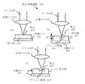
図3(a)乃至図3(c)は可動ステージ257を用いてなされる焦点深度調節300の拡大図を示し、焦点310およびアブレーション領域312を含んでいる。明確にするため、レーザ孔開け装置200の追加構成要素が図3(a)乃至図3(c)で示されている。 FIGS. 3 (a) to 3 (c) show enlarged views of the depth of focus adjustment 300 made using the
図3(a)に図示するとおり、走査レンズ240は、材料のアブレーションのためにビーム107を加工物112の表面上の焦点310に向ける。図3(b)はアブレーション領域312がビーム107によって形成され、それによって焦点310がアブレーション層の深さと等しい距離だけ位置ずれした状態になる様子を図示している。可動ステージ257の送り距離と方向は本発明ではΔZとして表されている。 As shown in FIG. 3 (a), the scanning lens 240 directs the beam 107 to a
図3(c)は、加工物112の接触面上でビーム107の焦点を合わせ直すためになされる調節(ΔZで示される)を示している。可動ステージ257が移動する距離(ΔZ)は算出されたアブレーション速度に基づいてあらかじめ決定されている。
動作時には、加工物112の接触面上のビーム107の焦点310に対して焦点深度の初期設定が決められる。アブレーション領域312が形成されると、制御ユニット(図示せず)が可動ステージ257の送り距離(ΔZ)を機械的に調節して、ビーム107の焦点310をアブレーションされる次の層の深さに位置合わせし直す。この技術によって、選択された焦点深度領域110内の焦点310に対して一定のレーザ強度を提供しながら加工物112内で材料が連続的にアブレーションされる。FIG. 3 (c) shows the adjustment (indicated by ΔZ) made to refocus the beam 107 on the contact surface of the workpiece 112. The distance (ΔZ) that the
In operation, an initial depth of focus is determined for the
図4はレーザ孔開け装置200の焦点深度を調節する方法400を示す。ここで図1乃至図3を参照して各ステップを説明する。 FIG. 4 shows a method 400 for adjusting the depth of focus of the laser drilling device 200. Each step will now be described with reference to FIGS.
ステップ410において、目標の孔形状寸法が決定される。このステップでは、操作者または技術者が、CADファイルや技術注記等の顧客指定の情報を用いてテーパ角度、出口孔の直径、入口孔の直径などの所望の孔形状寸法を決定する。本発明では、所望の形状および寸法は円形の孔である。しかしながら、この発明は指定された形状に限定されるものではなく、直線、曲線、方形等の一般的なパターンの形状寸法の孔開けにも適用できる。 In
ステップ420において、レーザアブレーション速度が実験的に求められる。このステップでは、操作者または技術者は、一組の所定のレーザ孔開けパラメータを用いてアブレーション速度(または材料除去速度)を求める。アブレーション速度の制御パラメータには、繰り返し数、スポットサイズおよびレーザ出力が含まれる。加工物112を切削する前に、試し切削を複数回行ってアブレーション速度を計測し、アブレーション速度に影響を与えるようなレーザ孔開け装置200の調節を行う。 In
ステップ430で、加工物孔の最終仕上げ深さが設定される。このステップでは、操作者または技術者が、加工物112の材料厚みとステップ410で得られた所望の孔形状を用いて加工物112の最終仕上げの所望の孔深さを決定する。 At step 430, the final finish depth of the workpiece hole is set. In this step, an operator or technician uses the material thickness of the workpiece 112 and the desired hole shape obtained in
ステップ440で、送り速度が求められる。このステップでは、操作者、技術者または自動化されたツールが、ステップ410,420,430で得られた計算値を用いて、可動ステージ257の送り速度を求める。送り速度は、如何なる孔開け用途の場合でも、単位時間あたりのアブレーション深さで表された、上記求められたアブレーション速度と等しい。例えば、アブレーション速度が、所定のレーザパラメータ群について特定の材料、大きさおよび形状で1μm/秒と求められる場合、送り速度は1μm/秒となるであろう。 At
ステップ450で、データが制御ユニットに入力される。このステップでは、操作者、技術者または自動化されたツールが、可動ステージ257を調節できるように、ステップ420,430および440で得られたデータを制御ユニットに入力する。 At
ステップ460で、加工物がアブレーションされる。このステップで、レーザ孔開け装置200は焦点深度パラメータを加工物112の表面に合わせて調節する。その後、レーザ孔開け装置200は切削アルゴリズムを実行して加工物112内の材料をアブレーションする。あらかじめ設定されたアブレーション深さでの全アブレーション領域312内の加工物112のアブレーションは、ステップ420で求められたアブレーション速度に基づく。 At
ステップ470では、所望の孔深さが達成されたかどうかが判定される。この判定ステップで、切削アルゴリズムは所望の切削形状が達成されたかどうかを判定する。切削アルゴリズムが所定数のアブレーション層を完成し、可動ステージ257がステップ430で求められた所望の孔深さに対する所定の設定点を達成した時に、切削形状が達成されたと見なされる。「Yes」の場合、方法400は終了する。「No」の場合、方法400はステップ420に戻る。 In
本発明はいくつかの利点を有する。本発明の第1の利点は、レーザ孔開けされた最終製品の品質仕様を管理する方法を提供することである。本発明の第2の利点は、厚い加工物上でレーザ孔開けを制御する方法を提供することである。本発明の第3の利点は、孔開け加工の間中、厚い加工物の表面で一定のアブレーション速度を維持する方法を提供することである。本発明の第4の利点は、孔開け加工の間中、厚い加工物の表面上で一定のレーザビーム強度と一定のスポットサイズを維持する方法を提供することである。本発明の第5の利点は、わずか1つの可動要素を用いて焦点深度を調節する方法を提供することである。本発明の第6の利点は、材料の厚みを考慮することなく簡略化されたパターンを作成できることである。 The present invention has several advantages. A first advantage of the present invention is that it provides a method for managing the quality specifications of the laser drilled final product. A second advantage of the present invention is to provide a method for controlling laser drilling on thick workpieces. A third advantage of the present invention is to provide a method that maintains a constant ablation rate on the surface of a thick workpiece throughout the drilling process. A fourth advantage of the present invention is to provide a method for maintaining a constant laser beam intensity and a constant spot size on the surface of a thick workpiece throughout the drilling process. A fifth advantage of the present invention is to provide a method for adjusting the depth of focus using as few as one movable element. A sixth advantage of the present invention is that a simplified pattern can be created without considering the thickness of the material.
本発明にはいくつかの不具合もある。本発明の不具合の1つは、可動ステージの送り速度が遅すぎると、本発明でむらのない孔形状を維持することが難しいことである。しかしながら、微細加工の分野における工作機械設備のハードウェアおよびソフトウェア並びにマイクロ制御装置のさらなる発展によってこの懸念領域はまもまく改善されるであろう。
本発明が取り組んだものと同一の1つまたは複数の課題を解決する別の方法も存在する。同一の課題を解決するある別の方法とは、個々のレーザ装置構成要素(例えば走査レンズ)を手動で調節することによってレーザ孔開け装置の焦点深度を調節することである。しかしながら、この技術は時間がかかり、煩わしく、レーザ孔開け装置に光学的な位置合わせの問題を持ち込む可能性がある。The present invention also has several drawbacks. One of the problems of the present invention is that it is difficult to maintain a uniform hole shape in the present invention when the feed rate of the movable stage is too slow. However, further development of machine tool hardware and software and microcontrollers in the field of microfabrication will improve this area of concern.
There are other ways to solve the same problem or problems addressed by the present invention. Another way to solve the same problem is to adjust the depth of focus of the laser drilling device by manually adjusting individual laser device components (eg, scanning lenses). However, this technique is time consuming and cumbersome and can introduce optical alignment problems into the laser drilling device.
本発明の説明は本質的に例示に過ぎず、ゆえに本発明の主旨から逸脱しない種々の変形は本発明の範囲内にあることが意図されている。そのような変形は本発明の精神および範囲から逸脱しないものと見なされるべきである。 The description of the invention is merely exemplary in nature and, thus, various modifications that do not depart from the gist of the invention are intended to be within the scope of the invention. Such variations are to be considered as not departing from the spirit and scope of the present invention.
Claims (24)
Translated fromJapanese焦点面を有するレーザビームと、
表面が前記焦点面と交差する点で前記レーザビームに晒される加工物と、
前記加工物と前記焦点面のうちの少なくとも一方の位置を調節することにより、孔開け加工の間中、前記加工物の前記露出面上で一定のアブレーション速度を維持するよう動作可能な制御モジュールとを備える装置。A depth of focus control device used with a laser drilling device,
A laser beam having a focal plane;
A workpiece exposed to the laser beam at a point where a surface intersects the focal plane;
A control module operable to maintain a constant ablation rate on the exposed surface of the workpiece during drilling by adjusting a position of at least one of the workpiece and the focal plane; A device comprising:
前記制御モジュールは前記可動ステージの位置を調節するよう動作可能である請求項1記載の装置。Comprising a movable stage operable to support the workpiece;
The apparatus of claim 1, wherein the control module is operable to adjust a position of the movable stage.
前記レーザビームに対する前記加工物の材料のアブレーション速度と、
前記孔開け加工の結果前記加工物に形成された形状と、
前記孔開け加工の間、前記加工物に前記形状を形成するよう採用された工具経路と、
前記孔開け加工の間、前記工具経路を用いて前記加工物に前記形状を形成するアルゴリズムとの関数として、
前記可動ステージの位置を調節するよう動作可能な請求項2記載の装置。The control module is
Ablation rate of the workpiece material relative to the laser beam;
The shape formed in the workpiece as a result of the drilling process;
A tool path adapted to form the shape on the workpiece during the drilling; and
During the drilling process, as a function of an algorithm that forms the shape on the workpiece using the tool path,
The apparatus of claim 2, wherein the apparatus is operable to adjust a position of the movable stage.
前記レーザビームに対する前記加工物の材料のアブレーション速度と、
前記孔開け加工の結果前記加工物に形成された形状との関数として、
前記加工物と前記焦点面のうちの少なくとも一方の位置を調節するよう動作可能な請求項1記載の装置。The control module is
Ablation rate of the workpiece material relative to the laser beam;
As a function of the shape formed in the workpiece as a result of the drilling process,
The apparatus of claim 1, wherein the apparatus is operable to adjust a position of at least one of the workpiece and the focal plane.
前記孔開け加工の間、前記加工物に前記形状を形成する工具経路と、
前記孔開け加工の間、前記工具経路を用いて前記加工物に前記形状を形成するアルゴリズムとの関数として、
前記加工物と前記焦点面のうちの少なくとも一方の位置を調節するよう動作可能な請求項9記載の装置。The control module is
A tool path that forms the shape in the workpiece during the drilling;
During the drilling process, as a function of an algorithm that forms the shape on the workpiece using the tool path,
The apparatus of claim 9, wherein the apparatus is operable to adjust a position of at least one of the workpiece and the focal plane.
前記制御モジュールは前記走査レンズの位置を調節するよう動作可能な請求項1記載の装置。A movable scanning lens adapted to focus the laser beam on a surface of the workpiece;
The apparatus of claim 1, wherein the control module is operable to adjust the position of the scanning lens.
焦点面を有するレーザビームを生成する工程と、
前記焦点面上に、該焦点面と交差する点で表面が前記レーザビームに晒される加工物を位置付けする工程と、
前記加工物と前記焦点面のうちの少なくとも一方の位置を調節することにより、孔開け加工の間中、前記加工物の前記露出面上で一定のアブレーション速度を維持する工程とを含む方法。A method of adjusting the depth of focus of a laser cutting device,
Generating a laser beam having a focal plane;
Positioning on the focal plane a workpiece whose surface is exposed to the laser beam at a point intersecting the focal plane;
Maintaining a constant ablation rate on the exposed surface of the workpiece during drilling by adjusting a position of at least one of the workpiece and the focal plane.
前記レーザビームに対する前記加工物の材料のアブレーション速度と、
前記孔開け加工の結果前記加工物に形成された形状と、
前記孔開け加工の間、前記加工物に前記形状を形成するよう採用された工具経路と、
前記孔開け加工の間、前記工具経路を用いて前記加工物に前記形状を形成するアルゴリズムとの関数として、
前記可動ステージの位置を調節するよう動作可能な請求項13記載の方法。The control module is
Ablation rate of the workpiece material relative to the laser beam;
The shape formed in the workpiece as a result of the drilling process;
A tool path adapted to form the shape on the workpiece during the drilling; and
During the drilling process, as a function of an algorithm that forms the shape on the workpiece using the tool path,
The method of claim 13, wherein the method is operable to adjust a position of the movable stage.
前記孔開け加工の結果前記加工物に形成された形状との関数として、
前記加工物と前記焦点面のうちの少なくとも一方の位置を調節する工程を含む請求項12記載の方法。Ablation rate of the workpiece material relative to the laser beam;
As a function of the shape formed in the workpiece as a result of the drilling process,
The method of claim 12, comprising adjusting a position of at least one of the workpiece and the focal plane.
前記孔開け加工の間、前記工具経路を用いて前記加工物に前記形状を形成するアルゴリズムとの関数として、
前記加工物と前記焦点面のうちの少なくとも一方の位置を調節する工程を含む請求項20記載の方法。A tool path that forms the shape in the workpiece during the drilling; and
During the drilling process, as a function of an algorithm that forms the shape on the workpiece using the tool path,
21. The method of claim 20, comprising adjusting a position of at least one of the workpiece and the focal plane.
Applications Claiming Priority (5)
| Application Number | Priority Date | Filing Date | Title |
|---|---|---|---|
| US39846902P | 2002-07-25 | 2002-07-25 | |
| US60/398,469 | 2002-07-25 | ||
| US10/266,999US6787734B2 (en) | 2002-07-25 | 2002-10-08 | System and method of laser drilling using a continuously optimized depth of focus |
| US10/266,999 | 2002-10-08 | ||
| PCT/US2003/005909WO2004011187A1 (en) | 2002-07-25 | 2003-02-26 | System and method of laser drilling using a continuously optimized depth of focus |
Publications (1)
| Publication Number | Publication Date |
|---|---|
| JP2006503713Atrue JP2006503713A (en) | 2006-02-02 |
Family
ID=30772609
Family Applications (1)
| Application Number | Title | Priority Date | Filing Date |
|---|---|---|---|
| JP2005505592APendingJP2006503713A (en) | 2002-07-25 | 2003-02-26 | Laser drilling apparatus and method using continuously optimized depth of focus |
Country Status (6)
| Country | Link |
|---|---|
| EP (1) | EP1525069B1 (en) |
| JP (1) | JP2006503713A (en) |
| CN (1) | CN1313239C (en) |
| AT (1) | ATE428531T1 (en) |
| AU (1) | AU2003212424A1 (en) |
| DE (1) | DE60327206D1 (en) |
Cited By (4)
| Publication number | Priority date | Publication date | Assignee | Title |
|---|---|---|---|---|
| JP2011079300A (en)* | 2009-08-26 | 2011-04-21 | Hueck Rheinische Gmbh | Method for producing surface structure for metallic press plate, endless belt or embossing roller |
| JP2013169559A (en)* | 2012-02-20 | 2013-09-02 | Sumitomo Heavy Ind Ltd | Laser beam machining apparatus and laser beam machining method |
| CN113305448A (en)* | 2021-05-28 | 2021-08-27 | 苏州科韵激光科技有限公司 | Focal depth automatic compensation method, device and system |
| WO2022162768A1 (en)* | 2021-01-27 | 2022-08-04 | ギガフォトン株式会社 | Laser processing method and laser processing system |
Families Citing this family (4)
| Publication number | Priority date | Publication date | Assignee | Title |
|---|---|---|---|---|
| CN101832759B (en)* | 2010-04-06 | 2012-06-27 | 清华大学 | Method for making micro-nano-scale speckle |
| WO2015113302A1 (en)* | 2014-01-30 | 2015-08-06 | 西门子公司 | Simulation system and method for laser drilling process |
| CN115716171B (en)* | 2022-12-01 | 2024-07-23 | 温州大学平阳智能制造研究院 | Self-adaptive laser drilling method based on coaxial monitoring |
| CN118070563B (en)* | 2024-04-17 | 2024-06-21 | 季华实验室 | Deformed geometry laser ablation simulation method, device, electronic device and storage medium |
Family Cites Families (13)
| Publication number | Priority date | Publication date | Assignee | Title |
|---|---|---|---|---|
| US4689467A (en)* | 1982-12-17 | 1987-08-25 | Inoue-Japax Research Incorporated | Laser machining apparatus |
| FR2547519B1 (en)* | 1983-06-15 | 1987-07-03 | Snecma | LASER DRILLING METHOD AND DEVICE |
| JPH0798274B2 (en)* | 1986-12-22 | 1995-10-25 | 大成建設株式会社 | Method and apparatus for cutting solid material by laser irradiation |
| US5063280A (en)* | 1989-07-24 | 1991-11-05 | Canon Kabushiki Kaisha | Method and apparatus for forming holes into printed circuit board |
| JPH0366488A (en)* | 1989-08-02 | 1991-03-22 | Mitsubishi Electric Corp | Laser drilling method |
| JPH05208288A (en)* | 1992-01-16 | 1993-08-20 | Hitachi Ltd | Laser processing method and apparatus |
| JP3185580B2 (en)* | 1995-01-31 | 2001-07-11 | 三菱電機株式会社 | Laser processing apparatus and processing method |
| WO1997019217A2 (en)* | 1995-11-21 | 1997-05-29 | Loughborough University Innovations Limited | Control methods and apparatus |
| JPH09253877A (en)* | 1996-03-25 | 1997-09-30 | Sumitomo Electric Ind Ltd | Excimer laser processing method and processed substrate |
| JP3474774B2 (en)* | 1998-05-29 | 2003-12-08 | リコーマイクロエレクトロニクス株式会社 | Method for manufacturing nozzle plate of inkjet head |
| JP3407715B2 (en)* | 2000-06-06 | 2003-05-19 | 松下電器産業株式会社 | Laser processing equipment |
| JP2002001563A (en)* | 2000-06-27 | 2002-01-08 | Toshiba Tec Corp | Laser processing apparatus and method |
| BR0211321A (en)* | 2001-07-02 | 2004-07-13 | Virtek Laser Systems Inc | Method and apparatus for ablating an opening on a hard, non-metallic substrate and hard, clear, non-metallic workpiece |
- 2003
- 2003-02-26ATAT03709364Tpatent/ATE428531T1/ennot_activeIP Right Cessation
- 2003-02-26JPJP2005505592Apatent/JP2006503713A/enactivePending
- 2003-02-26DEDE60327206Tpatent/DE60327206D1/ennot_activeExpired - Lifetime
- 2003-02-26EPEP03709364Apatent/EP1525069B1/ennot_activeExpired - Lifetime
- 2003-02-26AUAU2003212424Apatent/AU2003212424A1/ennot_activeAbandoned
- 2003-02-26CNCNB038126907Apatent/CN1313239C/ennot_activeExpired - Fee Related
Cited By (5)
| Publication number | Priority date | Publication date | Assignee | Title |
|---|---|---|---|---|
| JP2011079300A (en)* | 2009-08-26 | 2011-04-21 | Hueck Rheinische Gmbh | Method for producing surface structure for metallic press plate, endless belt or embossing roller |
| JP2013169559A (en)* | 2012-02-20 | 2013-09-02 | Sumitomo Heavy Ind Ltd | Laser beam machining apparatus and laser beam machining method |
| WO2022162768A1 (en)* | 2021-01-27 | 2022-08-04 | ギガフォトン株式会社 | Laser processing method and laser processing system |
| CN113305448A (en)* | 2021-05-28 | 2021-08-27 | 苏州科韵激光科技有限公司 | Focal depth automatic compensation method, device and system |
| CN113305448B (en)* | 2021-05-28 | 2022-05-27 | 苏州科韵激光科技有限公司 | Focal depth automatic compensation method, device and system |
Also Published As
| Publication number | Publication date |
|---|---|
| EP1525069B1 (en) | 2009-04-15 |
| EP1525069A4 (en) | 2006-05-24 |
| CN1658997A (en) | 2005-08-24 |
| EP1525069A1 (en) | 2005-04-27 |
| CN1313239C (en) | 2007-05-02 |
| ATE428531T1 (en) | 2009-05-15 |
| AU2003212424A1 (en) | 2004-02-16 |
| DE60327206D1 (en) | 2009-05-28 |
Similar Documents
| Publication | Publication Date | Title |
|---|---|---|
| US6787734B2 (en) | System and method of laser drilling using a continuously optimized depth of focus | |
| US20210316400A1 (en) | Laser processing apparatus, methods of laser-processing workpieces and related arrangements | |
| US6627844B2 (en) | Method of laser milling | |
| JP4551086B2 (en) | Partial machining with laser | |
| JP4284057B2 (en) | Laser fine processing equipment | |
| US6897405B2 (en) | Method of laser milling using constant tool path algorithm | |
| JP3901716B2 (en) | Method for calculating minimum pulse width of short pulse laser device, method for forming a plurality of holes using short pulse laser device, and short pulse laser device | |
| JP2797684B2 (en) | Nozzle manufacturing method and manufacturing apparatus | |
| TWI460043B (en) | Method and apparatus for laser drilling holes with gaussian pulses | |
| US6710288B2 (en) | Method and apparatus for aligning a work piece in a laser drilling system | |
| RU2750313C2 (en) | Method for laser processing of metal material with a high level of dynamic control of the axes of movement of the laser beam along a pre-selected processing path, as well as a machine and a computer program for implementing this method | |
| JP2004528991A5 (en) | ||
| TWI535516B (en) | Minimizing thermal effect during material removal using a laser | |
| JPH0810970A (en) | Method and equipment of laser beam machining | |
| JP2002018585A (en) | Method and apparatus for drilling holes with a sub-wavelength pitch using a laser | |
| JP2008503355A (en) | Substrate material cutting, dividing or dividing apparatus, system and method | |
| JP5873978B2 (en) | Laser processing method and nozzle manufacturing method | |
| JPH1034365A (en) | Laser micro-perforation method and laser micro-perforation device | |
| KR100953185B1 (en) | Method and apparatus for irradiating laser using non-spinning optical system, method and apparatus for trimming film register using same, and method for manufacturing printed circuit board | |
| JP2006503713A (en) | Laser drilling apparatus and method using continuously optimized depth of focus | |
| Breitling et al. | Drilling of metals | |
| JPH10286683A (en) | Excimer laser processing apparatus and processing method | |
| EP2963743A1 (en) | Laser processing apparatus | |
| KR102830817B1 (en) | Laser processing method for printed circuit board and laser processing machine for printed circuit board | |
| JPWO2020251782A5 (en) |
Legal Events
| Date | Code | Title | Description |
|---|---|---|---|
| A621 | Written request for application examination | Free format text:JAPANESE INTERMEDIATE CODE: A621 Effective date:20060111 | |
| A131 | Notification of reasons for refusal | Free format text:JAPANESE INTERMEDIATE CODE: A131 Effective date:20090224 | |
| A521 | Request for written amendment filed | Free format text:JAPANESE INTERMEDIATE CODE: A523 Effective date:20090413 | |
| A131 | Notification of reasons for refusal | Free format text:JAPANESE INTERMEDIATE CODE: A131 Effective date:20090707 | |
| A521 | Request for written amendment filed | Free format text:JAPANESE INTERMEDIATE CODE: A523 Effective date:20090825 | |
| A02 | Decision of refusal | Free format text:JAPANESE INTERMEDIATE CODE: A02 Effective date:20091124 | |
| A521 | Request for written amendment filed | Free format text:JAPANESE INTERMEDIATE CODE: A523 Effective date:20100311 | |
| A521 | Request for written amendment filed | Free format text:JAPANESE INTERMEDIATE CODE: A523 Effective date:20101101 | |
| RD04 | Notification of resignation of power of attorney | Free format text:JAPANESE INTERMEDIATE CODE: A7424 Effective date:20110705 |