JP2006501947A - Orthopedic graft insertion devices and techniques - Google Patents
Orthopedic graft insertion devices and techniquesDownload PDFInfo
- Publication number
- JP2006501947A JP2006501947AJP2004543371AJP2004543371AJP2006501947AJP 2006501947 AJP2006501947 AJP 2006501947AJP 2004543371 AJP2004543371 AJP 2004543371AJP 2004543371 AJP2004543371 AJP 2004543371AJP 2006501947 AJP2006501947 AJP 2006501947A
- Authority
- JP
- Japan
- Prior art keywords
- guide
- instrument
- guide members
- members
- fixed arm
- Prior art date
- Legal status (The legal status is an assumption and is not a legal conclusion. Google has not performed a legal analysis and makes no representation as to the accuracy of the status listed.)
- Pending
Links
Images


Classifications
- A—HUMAN NECESSITIES
- A61—MEDICAL OR VETERINARY SCIENCE; HYGIENE
- A61F—FILTERS IMPLANTABLE INTO BLOOD VESSELS; PROSTHESES; DEVICES PROVIDING PATENCY TO, OR PREVENTING COLLAPSING OF, TUBULAR STRUCTURES OF THE BODY, e.g. STENTS; ORTHOPAEDIC, NURSING OR CONTRACEPTIVE DEVICES; FOMENTATION; TREATMENT OR PROTECTION OF EYES OR EARS; BANDAGES, DRESSINGS OR ABSORBENT PADS; FIRST-AID KITS
- A61F2/00—Filters implantable into blood vessels; Prostheses, i.e. artificial substitutes or replacements for parts of the body; Appliances for connecting them with the body; Devices providing patency to, or preventing collapsing of, tubular structures of the body, e.g. stents
- A61F2/02—Prostheses implantable into the body
- A61F2/30—Joints
- A61F2/46—Special tools for implanting artificial joints
- A61F2/4603—Special tools for implanting artificial joints for insertion or extraction of endoprosthetic joints or of accessories thereof
- A61F2/4611—Special tools for implanting artificial joints for insertion or extraction of endoprosthetic joints or of accessories thereof of spinal prostheses
- A—HUMAN NECESSITIES
- A61—MEDICAL OR VETERINARY SCIENCE; HYGIENE
- A61B—DIAGNOSIS; SURGERY; IDENTIFICATION
- A61B17/00—Surgical instruments, devices or methods
- A61B17/02—Surgical instruments, devices or methods for holding wounds open, e.g. retractors; Tractors
- A61B17/0206—Surgical instruments, devices or methods for holding wounds open, e.g. retractors; Tractors with antagonistic arms as supports for retractor elements
- A—HUMAN NECESSITIES
- A61—MEDICAL OR VETERINARY SCIENCE; HYGIENE
- A61B—DIAGNOSIS; SURGERY; IDENTIFICATION
- A61B17/00—Surgical instruments, devices or methods
- A61B17/02—Surgical instruments, devices or methods for holding wounds open, e.g. retractors; Tractors
- A61B17/025—Joint distractors
- A—HUMAN NECESSITIES
- A61—MEDICAL OR VETERINARY SCIENCE; HYGIENE
- A61B—DIAGNOSIS; SURGERY; IDENTIFICATION
- A61B17/00—Surgical instruments, devices or methods
- A61B17/02—Surgical instruments, devices or methods for holding wounds open, e.g. retractors; Tractors
- A61B17/025—Joint distractors
- A61B2017/0256—Joint distractors for the spine
- A—HUMAN NECESSITIES
- A61—MEDICAL OR VETERINARY SCIENCE; HYGIENE
- A61F—FILTERS IMPLANTABLE INTO BLOOD VESSELS; PROSTHESES; DEVICES PROVIDING PATENCY TO, OR PREVENTING COLLAPSING OF, TUBULAR STRUCTURES OF THE BODY, e.g. STENTS; ORTHOPAEDIC, NURSING OR CONTRACEPTIVE DEVICES; FOMENTATION; TREATMENT OR PROTECTION OF EYES OR EARS; BANDAGES, DRESSINGS OR ABSORBENT PADS; FIRST-AID KITS
- A61F2/00—Filters implantable into blood vessels; Prostheses, i.e. artificial substitutes or replacements for parts of the body; Appliances for connecting them with the body; Devices providing patency to, or preventing collapsing of, tubular structures of the body, e.g. stents
- A61F2/02—Prostheses implantable into the body
- A61F2/30—Joints
- A61F2/44—Joints for the spine, e.g. vertebrae, spinal discs
- A61F2/442—Intervertebral or spinal discs, e.g. resilient
- A—HUMAN NECESSITIES
- A61—MEDICAL OR VETERINARY SCIENCE; HYGIENE
- A61F—FILTERS IMPLANTABLE INTO BLOOD VESSELS; PROSTHESES; DEVICES PROVIDING PATENCY TO, OR PREVENTING COLLAPSING OF, TUBULAR STRUCTURES OF THE BODY, e.g. STENTS; ORTHOPAEDIC, NURSING OR CONTRACEPTIVE DEVICES; FOMENTATION; TREATMENT OR PROTECTION OF EYES OR EARS; BANDAGES, DRESSINGS OR ABSORBENT PADS; FIRST-AID KITS
- A61F2/00—Filters implantable into blood vessels; Prostheses, i.e. artificial substitutes or replacements for parts of the body; Appliances for connecting them with the body; Devices providing patency to, or preventing collapsing of, tubular structures of the body, e.g. stents
- A61F2/02—Prostheses implantable into the body
- A61F2/30—Joints
- A61F2/46—Special tools for implanting artificial joints
- A61F2/4603—Special tools for implanting artificial joints for insertion or extraction of endoprosthetic joints or of accessories thereof
- A—HUMAN NECESSITIES
- A61—MEDICAL OR VETERINARY SCIENCE; HYGIENE
- A61F—FILTERS IMPLANTABLE INTO BLOOD VESSELS; PROSTHESES; DEVICES PROVIDING PATENCY TO, OR PREVENTING COLLAPSING OF, TUBULAR STRUCTURES OF THE BODY, e.g. STENTS; ORTHOPAEDIC, NURSING OR CONTRACEPTIVE DEVICES; FOMENTATION; TREATMENT OR PROTECTION OF EYES OR EARS; BANDAGES, DRESSINGS OR ABSORBENT PADS; FIRST-AID KITS
- A61F2/00—Filters implantable into blood vessels; Prostheses, i.e. artificial substitutes or replacements for parts of the body; Appliances for connecting them with the body; Devices providing patency to, or preventing collapsing of, tubular structures of the body, e.g. stents
- A61F2/02—Prostheses implantable into the body
- A61F2/28—Bones
- A61F2002/2835—Bone graft implants for filling a bony defect or an endoprosthesis cavity, e.g. by synthetic material or biological material
- A—HUMAN NECESSITIES
- A61—MEDICAL OR VETERINARY SCIENCE; HYGIENE
- A61F—FILTERS IMPLANTABLE INTO BLOOD VESSELS; PROSTHESES; DEVICES PROVIDING PATENCY TO, OR PREVENTING COLLAPSING OF, TUBULAR STRUCTURES OF THE BODY, e.g. STENTS; ORTHOPAEDIC, NURSING OR CONTRACEPTIVE DEVICES; FOMENTATION; TREATMENT OR PROTECTION OF EYES OR EARS; BANDAGES, DRESSINGS OR ABSORBENT PADS; FIRST-AID KITS
- A61F2/00—Filters implantable into blood vessels; Prostheses, i.e. artificial substitutes or replacements for parts of the body; Appliances for connecting them with the body; Devices providing patency to, or preventing collapsing of, tubular structures of the body, e.g. stents
- A61F2/02—Prostheses implantable into the body
- A61F2/30—Joints
- A61F2002/30001—Additional features of subject-matter classified in A61F2/28, A61F2/30 and subgroups thereof
- A61F2002/30621—Features concerning the anatomical functioning or articulation of the prosthetic joint
- A61F2002/30622—Implant for fusing a joint or bone material
- A—HUMAN NECESSITIES
- A61—MEDICAL OR VETERINARY SCIENCE; HYGIENE
- A61F—FILTERS IMPLANTABLE INTO BLOOD VESSELS; PROSTHESES; DEVICES PROVIDING PATENCY TO, OR PREVENTING COLLAPSING OF, TUBULAR STRUCTURES OF THE BODY, e.g. STENTS; ORTHOPAEDIC, NURSING OR CONTRACEPTIVE DEVICES; FOMENTATION; TREATMENT OR PROTECTION OF EYES OR EARS; BANDAGES, DRESSINGS OR ABSORBENT PADS; FIRST-AID KITS
- A61F2/00—Filters implantable into blood vessels; Prostheses, i.e. artificial substitutes or replacements for parts of the body; Appliances for connecting them with the body; Devices providing patency to, or preventing collapsing of, tubular structures of the body, e.g. stents
- A61F2/02—Prostheses implantable into the body
- A61F2/30—Joints
- A61F2002/30001—Additional features of subject-matter classified in A61F2/28, A61F2/30 and subgroups thereof
- A61F2002/30667—Features concerning an interaction with the environment or a particular use of the prosthesis
- A61F2002/30677—Means for introducing or releasing pharmaceutical products, e.g. antibiotics, into the body
- A—HUMAN NECESSITIES
- A61—MEDICAL OR VETERINARY SCIENCE; HYGIENE
- A61F—FILTERS IMPLANTABLE INTO BLOOD VESSELS; PROSTHESES; DEVICES PROVIDING PATENCY TO, OR PREVENTING COLLAPSING OF, TUBULAR STRUCTURES OF THE BODY, e.g. STENTS; ORTHOPAEDIC, NURSING OR CONTRACEPTIVE DEVICES; FOMENTATION; TREATMENT OR PROTECTION OF EYES OR EARS; BANDAGES, DRESSINGS OR ABSORBENT PADS; FIRST-AID KITS
- A61F2/00—Filters implantable into blood vessels; Prostheses, i.e. artificial substitutes or replacements for parts of the body; Appliances for connecting them with the body; Devices providing patency to, or preventing collapsing of, tubular structures of the body, e.g. stents
- A61F2/02—Prostheses implantable into the body
- A61F2/30—Joints
- A61F2/46—Special tools for implanting artificial joints
- A61F2/4603—Special tools for implanting artificial joints for insertion or extraction of endoprosthetic joints or of accessories thereof
- A61F2002/4622—Special tools for implanting artificial joints for insertion or extraction of endoprosthetic joints or of accessories thereof having the shape of a forceps or a clamp
- A—HUMAN NECESSITIES
- A61—MEDICAL OR VETERINARY SCIENCE; HYGIENE
- A61F—FILTERS IMPLANTABLE INTO BLOOD VESSELS; PROSTHESES; DEVICES PROVIDING PATENCY TO, OR PREVENTING COLLAPSING OF, TUBULAR STRUCTURES OF THE BODY, e.g. STENTS; ORTHOPAEDIC, NURSING OR CONTRACEPTIVE DEVICES; FOMENTATION; TREATMENT OR PROTECTION OF EYES OR EARS; BANDAGES, DRESSINGS OR ABSORBENT PADS; FIRST-AID KITS
- A61F2/00—Filters implantable into blood vessels; Prostheses, i.e. artificial substitutes or replacements for parts of the body; Appliances for connecting them with the body; Devices providing patency to, or preventing collapsing of, tubular structures of the body, e.g. stents
- A61F2/02—Prostheses implantable into the body
- A61F2/30—Joints
- A61F2/46—Special tools for implanting artificial joints
- A61F2/4603—Special tools for implanting artificial joints for insertion or extraction of endoprosthetic joints or of accessories thereof
- A61F2002/4625—Special tools for implanting artificial joints for insertion or extraction of endoprosthetic joints or of accessories thereof with relative movement between parts of the instrument during use
- A61F2002/4627—Special tools for implanting artificial joints for insertion or extraction of endoprosthetic joints or of accessories thereof with relative movement between parts of the instrument during use with linear motion along or rotating motion about the instrument axis or the implantation direction, e.g. telescopic, along a guiding rod, screwing inside the instrument
- A—HUMAN NECESSITIES
- A61—MEDICAL OR VETERINARY SCIENCE; HYGIENE
- A61F—FILTERS IMPLANTABLE INTO BLOOD VESSELS; PROSTHESES; DEVICES PROVIDING PATENCY TO, OR PREVENTING COLLAPSING OF, TUBULAR STRUCTURES OF THE BODY, e.g. STENTS; ORTHOPAEDIC, NURSING OR CONTRACEPTIVE DEVICES; FOMENTATION; TREATMENT OR PROTECTION OF EYES OR EARS; BANDAGES, DRESSINGS OR ABSORBENT PADS; FIRST-AID KITS
- A61F2/00—Filters implantable into blood vessels; Prostheses, i.e. artificial substitutes or replacements for parts of the body; Appliances for connecting them with the body; Devices providing patency to, or preventing collapsing of, tubular structures of the body, e.g. stents
- A61F2/02—Prostheses implantable into the body
- A61F2/30—Joints
- A61F2/46—Special tools for implanting artificial joints
- A61F2/4603—Special tools for implanting artificial joints for insertion or extraction of endoprosthetic joints or of accessories thereof
- A61F2002/4625—Special tools for implanting artificial joints for insertion or extraction of endoprosthetic joints or of accessories thereof with relative movement between parts of the instrument during use
- A61F2002/4628—Special tools for implanting artificial joints for insertion or extraction of endoprosthetic joints or of accessories thereof with relative movement between parts of the instrument during use with linear motion along or rotating motion about an axis transverse to the instrument axis or to the implantation direction, e.g. clamping
- A—HUMAN NECESSITIES
- A61—MEDICAL OR VETERINARY SCIENCE; HYGIENE
- A61F—FILTERS IMPLANTABLE INTO BLOOD VESSELS; PROSTHESES; DEVICES PROVIDING PATENCY TO, OR PREVENTING COLLAPSING OF, TUBULAR STRUCTURES OF THE BODY, e.g. STENTS; ORTHOPAEDIC, NURSING OR CONTRACEPTIVE DEVICES; FOMENTATION; TREATMENT OR PROTECTION OF EYES OR EARS; BANDAGES, DRESSINGS OR ABSORBENT PADS; FIRST-AID KITS
- A61F2/00—Filters implantable into blood vessels; Prostheses, i.e. artificial substitutes or replacements for parts of the body; Appliances for connecting them with the body; Devices providing patency to, or preventing collapsing of, tubular structures of the body, e.g. stents
- A61F2/02—Prostheses implantable into the body
- A61F2/30—Joints
- A61F2/46—Special tools for implanting artificial joints
- A61F2002/4681—Special tools for implanting artificial joints by applying mechanical shocks, e.g. by hammering
Landscapes
- Health & Medical Sciences (AREA)
- Life Sciences & Earth Sciences (AREA)
- Engineering & Computer Science (AREA)
- Biomedical Technology (AREA)
- Surgery (AREA)
- Veterinary Medicine (AREA)
- Public Health (AREA)
- General Health & Medical Sciences (AREA)
- Animal Behavior & Ethology (AREA)
- Heart & Thoracic Surgery (AREA)
- Molecular Biology (AREA)
- Nuclear Medicine, Radiotherapy & Molecular Imaging (AREA)
- Medical Informatics (AREA)
- Transplantation (AREA)
- Orthopedic Medicine & Surgery (AREA)
- Physical Education & Sports Medicine (AREA)
- Vascular Medicine (AREA)
- Oral & Maxillofacial Surgery (AREA)
- Cardiology (AREA)
- Neurology (AREA)
- Prostheses (AREA)
Abstract
Translated fromJapaneseDescription
Translated fromJapanese本発明は、隣接する骨部分の間への移植片の配置をやり易くする器具に関する。 The present invention relates to an instrument that facilitates placement of an implant between adjacent bone portions.
本出願は、2002年10月8日出願の米国仮特許出願第60/416,908号の出願日の恩典を請求し、同仮特許出願の内容を参考文献として本願に援用する。
骨構造の修復と再構成は、隣接する骨部分をプレートなどで互いに直接固定することによって行われる場合もある。また、骨の成長を誘発する材料を隣接する骨部分の間に導入し、時間が経過すると骨接合部が固まってくるというようにする場合もある。場合によっては、骨成長誘発材料によって隣接する構造の間で骨が治癒し又は骨が成長したときに、隣接する骨部分に開通性を保てるだけの強度がないこともある。そのような場合には、安定性を増すため、メッシュ構造、ケージ、又は他の移植片を使って隣接する骨構造に係合させるようにしている。This application claims the benefit of the filing date of US Provisional Patent Application No. 60 / 416,908, filed Oct. 8, 2002, the contents of which are incorporated herein by reference.
Bone structure repair and reconstruction may be performed by directly fixing adjacent bone parts together with a plate or the like. In some cases, a material that induces bone growth is introduced between adjacent bone parts so that the bone joint becomes solidified over time. In some cases, the bone growth-inducing material may not be strong enough to maintain patency in adjacent bone portions when the bone heals or grows between adjacent structures. In such cases, mesh structures, cages, or other implants are used to engage adjacent bone structures to increase stability.
このような移植片の問題点の1つとして、隣接する骨部分の間に移植片を配置することに付帯する問題がある。骨部分が接近しすぎている場合、又は隣接する組織、神経、又は血管が、骨部分と骨部分の間の空間へのアクセス又はその空間への移植片の配置を妨げている場合には、挿入が困難か又は時間がかかることになる。
本発明は、隣接する骨部分の間へ移植片を配置し易くする器具に関する。
或る態様によれば、移植片を挿入するための器具は、フレームを備えた近位部と、フレームから遠位方向に伸張する第1及び第2ガイド部材を備えた遠位部を含んでいる。第1及び第2ガイド部材は、それぞれ、近位端と遠位端の間に伸張している互いに反対側の第1側部及び第2側部と、この第1及び第2側部の間を近位端から遠位端まで伸張しているガイド面と、第1及び第2側部の一方だけに沿って伸張し、第1及び第2ガイド部材の内の対応する一方のガイド部材のガイド面から他方のガイド部材のガイド面に向けて突き出しているガイドフランジと、を含んでいる。The present invention relates to an instrument that facilitates placement of an implant between adjacent bone portions.
According to an aspect, an instrument for inserting an implant includes a proximal portion with a frame and a distal portion with first and second guide members extending distally from the frame. Yes. The first and second guide members are respectively between opposite first and second sides extending between the proximal and distal ends and the first and second sides. A guide surface extending from the proximal end to the distal end, and extending along only one of the first and second sides, and corresponding one of the first and second guide members. And a guide flange protruding from the guide surface toward the guide surface of the other guide member.
別の態様によれば、器具を挿入するための器具は、固定アームと、固定アームに連結された可動アームとを有するフレームを備えた近位部を含んでいる。この器具は、可動アームから遠位方向に伸張している第1ガイド部材と、固定アームから遠位方向に伸張している第2ガイド部材を含んでいる。第1及び第2ガイド部材は、それぞれ、相手側ガイド部材のガイド面に向いたガイド面を含んでいる。第1及び第2ガイド部材は、可動アームを固定アームに対して動かすことにより、お互いに接近したり離れたりする。 According to another aspect, an instrument for inserting an instrument includes a proximal portion with a frame having a fixed arm and a movable arm coupled to the fixed arm. The instrument includes a first guide member extending distally from the movable arm and a second guide member extending distally from the fixed arm. The first and second guide members each include a guide surface facing the guide surface of the counterpart guide member. The first and second guide members move toward and away from each other by moving the movable arm relative to the fixed arm.
別の態様によれば、移植片を挿入するための器具は、第1ガイド部材と、第1ガイド部材に沿って伸張している第2ガイド部材とを備えた、遠位部を含んでいる。第1及び第2ガイド部材は、それぞれ、互いにとって相手方の第1及び第2ガイド部材のガイド面に面し且つそれと略平行に配置されたガイド面を含んでいる。器具の近位部は、第1及び第2ガイド部材に連結されたフレームを含んでいる。フレームは、ガイド面を略平行に保ちつつ、第1及び第2ガイド部材を互いに対して接近させたり離したりできるように構成されている。 According to another aspect, an instrument for inserting an implant includes a distal portion with a first guide member and a second guide member extending along the first guide member. . The first and second guide members each include a guide surface that faces the guide surfaces of the counterpart first and second guide members and is disposed substantially parallel thereto. The proximal portion of the instrument includes a frame coupled to the first and second guide members. The frame is configured to allow the first and second guide members to approach and separate from each other while keeping the guide surfaces substantially parallel.
別の態様によれば、隣接する骨部分の間の空間に移植片を挿入するための器具は、それぞれ遠位端と近位端の間に伸張している第1部材と第2部材を含んでいる。第2部材は、第1部材に連結さており、第1及び第2部材の遠位端同士の間に移植片を解放可能に把持するため、第1部材に対して可動になっている。第1及び第2部材の一方の近位端は、第1及び第2部材の他方の近位端よりも更に近位方向に、隣接する骨部分の間の空間へ移植片を挿入し易くするための、嵌入力を受けるための嵌入ヘッドまで伸張している。 According to another aspect, an instrument for inserting a graft into a space between adjacent bone portions includes a first member and a second member that extend between a distal end and a proximal end, respectively. It is out. The second member is coupled to the first member and is movable relative to the first member to releasably grasp the graft between the distal ends of the first and second members. One proximal end of the first and second members facilitates insertion of the implant into the space between adjacent bone portions more proximally than the other proximal end of the first and second members. For this reason, it extends to the insertion head for receiving the fitting input.
更に別の態様によれば、隣接する骨部分の間の空間にテーパー付移植片を詰めるための器具は、軸を備えた近位部と、頭部を備えた遠位部とを含んでいる。頭部は、本体と楔部材を含んでいる。本体は、本体に押し付けて配置されたテーパー付移植片に充填力を加えるための遠位端面を含んでいる。楔部材は、本体の端面から遠位方向に伸張しており、遠位端面がテーパー付移植片に隣接して配置されると、テーパー付移植片の隣接するテーパー付端面に沿って配置することができる。楔部材は、テーパー付端面に沿って、テーパー付移植片のテーパー付面とは反対側の第2面に略平行な一時的な面を形成する。 According to yet another aspect, an instrument for packing a tapered implant in a space between adjacent bone portions includes a proximal portion with a shaft and a distal portion with a head. . The head includes a main body and a wedge member. The body includes a distal end surface for applying a filling force to the tapered graft disposed against the body. The wedge member extends distally from the end surface of the body and, when the distal end surface is disposed adjacent to the tapered graft, is disposed along the adjacent tapered end surface of the tapered graft. Can do. The wedge member forms a temporary surface along the tapered end surface that is substantially parallel to the second surface opposite the tapered surface of the tapered graft.
上記及びこの他の態様は、以下の説明及び添付図面から認識頂けるであろう。 These and other aspects will be appreciated from the following description and accompanying drawings.
本発明の原理の理解を深めるために、これより図面に示す実施形態を参照してゆくが、その際、特別な用語を使いながら説明する。しかしながら、これによって本発明の範囲を限定するものではない。本発明が関係する技術分野における当業者であれば、ここに例として示す装置に対する様々な変更及び修正、並びに本願に示す発明原理の別の用途を、当然のこととして想起するであろう。 For a better understanding of the principles of the present invention, reference will now be made to the embodiments illustrated in the drawings, in which specific language is used for explanation. However, this does not limit the scope of the present invention. Those skilled in the art to which the present invention pertains will naturally envision various changes and modifications to the apparatus illustrated by way of example, as well as other uses of the inventive principles described herein.
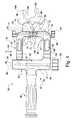
隣接する骨部分を支えるために隣接する骨部分の間の空間に、移植片及び他の装置を挿入するための器具が提供されている。挿入機器具は、隣接する骨部分に係合させるための現在のメッシュ又はケージ型装置に使用することができるが、他の型式の骨支持装置に使用することも考えられる。挿入機器具は、隣接する椎骨の間の円板空間に移植片を挿入するための脊椎外科処置に利用することができる。図1から図4の図示の実施形態では、隣接する骨部分は、第1椎骨140と第2椎骨142を含んでいる。椎骨140、142は、両者の間に円板空間144を有しており、この空間は、隣接する骨部分の間に移植片を挿入するための空間を提供している。挿入機器具は、隣接する椎骨の間の、1つ又はそれ以上の除去された又は部分的に除去された椎体の何れかの側に移植片を配置する手根骨切除術に使用することもできる。挿入機器具は、後方、後側方、経孔式、側方、前側方、前方進入を含む、脊椎への各種進入法に使用することができる。挿入機器具は、脊椎外科処置以外の外科処置でも、隣接する骨部分の間に移植片を挿入し易くするために利用することができると考えている。 An instrument is provided for inserting implants and other devices into the space between adjacent bone portions to support the adjacent bone portions. The insertion device can be used with current mesh or cage type devices for engaging adjacent bone portions, but it is also contemplated for use with other types of bone support devices. The insertion instrument can be utilized in spinal surgery procedures for inserting a graft into the disc space between adjacent vertebrae. In the illustrated embodiment of FIGS. 1-4, the adjacent bone portion includes a
図1から図4は、挿入機器具20を示している。挿入機器具20は、近位フレーム部22と遠位部24を含んでいる。遠位部24には、隣接する骨部分の間の空間への移植片の配置を案内するための一対のガイド部材70、90が設けられている。ガイド部材70、90は、近位フレーム部22を介して動かして、隣接する骨部分及び/又はガイド部材70、90の間に所望の空間を作り出すことができる。近位フレーム部22は、遠位部24を遠隔操作で動かし再配置して、ガイド部材70、90を隣接する骨部分の間の空間に整列させて配置することができる。近位フレーム部22は、更に、遠位部24を所望位置に解除可能に維持することもできる。送入機器具20は、切開又は侵襲性最小限の処置で、隣接する骨部分の間の空間にアクセスするために使用することができる。更に、近位フレーム部22には、遠位部24のガイド部材70、90の間の空間の調整を行う調整機構38を設けてもよい。 1 to 4 show an
近位フレーム部22は、遠位部24の位置又は間隔を調整することのできるどの様な装置又は機構を含んでいてもよい。近位フレーム部22は、例えば、リンクシステム、ワイヤシステム、ギヤシステム、及び可撓性を有する調整システムを含んでいてもよい。近位フレーム部22は、直線式及び/又は回転式移動要素を含んでいてもよい。近位フレーム部22は、遠位部24に永久的に固定されていてもよいし、遠位部24に取り外し可能に固定されていてもよいし、永久固定と取り外し可能固定の組み合わせであってもよい。近位フレーム部22の構成要素の適した例には、例えば、中実軸様要素、棒材、管状要素、ロッド様要素、リンケージ、弾性変形可能部材、及び連接コネクタなどが含まれる。近位フレーム部22の調整機構38は、ガイド部材70、90の間の数多くの相対位置の何れの位置にでも遠位部24を配置及び/又は維持することができ、遠位部24の1つ又はそれ以上の構成要素を特定の位置に固定するための手段が設けられている。
遠位部24は、調整機構38によって互いに可動的に離したり接近させたりして、隣接する骨構造を拡張又は接触させる、一対のガイド部材70、90を含んでいる。ガイド部材70、90は、互いに対して平行な関係で動かすため近位フレーム部22に結合されているが、平行でない運動も考えられる。遠位部24は、ガイド部材70、90を隣接する骨部分の間の空間に挿入するための低輪郭の配置状態を有している。ガイド部材70、90は、骨構造に対する拡張部材の運動に抗するために、骨構造に係合するための手段を含んでいる。このような係合手段には、例えば、ピット、ローレット、セレーション、歯、リッジ、逆棘、スパイク、山と谷、溝などが含まれる。 The
ガイド部材70、90は、近位フレーム部22から遠位方向に伸張し、椎骨140、142の様な隣接する骨部分の間に移植片を挿入するための経路を画定している。ガイド部材70は、近位端72から遠位端74まで伸張する本体76を含んでいる。本体76には、その一方の側に沿ってガイドフランジ78が設けられている。本体76に沿って近位端72と遠位端74の間にガイド面80が伸張している。同様に、ガイド部材90は、近位端92から遠位端94まで伸張する本体96を含んでいる。本体96には、その一方の側に沿って、ガイドフランジ78の反対側に配置されたガイドフランジ98が設けられている。ガイド面100は、本体96に沿って伸張し、ガイド面80の方を向いており、両者の間に移植片120の様な移植片を受け入れるための案内経路を形成している。ガイド面100は、近位端92と遠位端94の間に伸張している。
ガイド部材70の遠位端74には、隣接する骨構造に接して隣接する骨部分の間の空間へのガイド部材70の挿入深度を制限するための、遠位端74からガイド面80と反対方向に伸張する当接部材82が設けられている。支持部材84は、当接部材82から遠位方向に、隣接する骨部分の間の空間へと伸張して、ガイド面80の伸張部を形成している。ガイド部材90の遠位端94には、隣接する骨構造に接して隣接する骨部分の間の空間へのガイド部材90の挿入深度を制限するための、遠位端94から伸張する当接部材102が設けられている。支持部材104は、当接部材102から遠位方向に、隣接する骨部分の間の空間へと伸張して、ガイド面100の伸張部を形成している。 The
支持部材84、104は、隣接する骨部分の間の空間へ移植片120を挿入し易くするために、隣接する骨部分の隣接する面に沿って伸張している。支持部材84、104も、隣接する骨部分に接して、これに対する拡張力又は牽引力を伝達する。近位フレーム部22を操作してガイド部材70、90を離すことによって、拡張又は牽引力が、隣接する骨部分に加えられることになる。支持部材84、104は、更に、隣接する骨部分の間の空間に移植片120が配置される際に、隣接する椎骨終板を保護する。支持部材84、104は、移植片120が、骨構造の間の空間への入口で骨構造に食い込んだり、又はこれに係合するのを防いで、移植片120を隣接する骨部分の間の空間内の所望の位置に挿入し易くする。
移植片120が、ガイド部材70、90の間を隣接する骨部分の間へと案内される際、移植片120の、矢印122(図3)で示す頭/尾方向の位置は、ガイド面80、100が移植片120と接触することによって制御される。ガイド面80、100は、移植片120を隣接する骨部分の間の空間に整列させる。移植片120のガイド部材70、90に沿う横方向の位置は、ガイドフランジ79、98によって制御されるので、移植片120は、骨部分の間の空間へ接近する際に、ガイド部材70、90の間から滑り出て、骨部分に隣接する組織、神経、血管、又は他の組織構造に接触し又は損傷を与える恐れはない。更に、フレーム部22は、ガイド部材70、90が、図3に示すように、近位端において実質的に遮られないようにして、ガイド部材70、90の遠位部が円板空間内にあるときでも、移植片120がガイド部材70、90の間に容易に配置できるように構成されている。 When the
ガイドフランジ78は、ガイド部材90に向かって伸張し、ガイド面80を超えて突き出し、これに沿って壁を形成している。同様に、ガイドフランジ98は、ガイド部材70に向けて伸張し、ガイド面100を超えて突き出し、これに沿って壁を形成している。ガイドフランジ98は、ガイド部材90の、ガイドフランジ78とは反対の側にある。ガイドフランジ78、98をガイド部材70、90の互いに反対の側に沿ってのみ配置することにより、ガイド部材70、90の間に追加的な空間が設けられ、移植片120をガイド部材70、90に沿って前進させる際に、外科医が工具などで移植片120にアクセスすることができるようになる。例えば、移植片120がガイド部材70、90の間に配置されたとき、移植片の上下面を視認できるようになる。ガイドフランジ78、98は、移植片120のガイド部材70、90に対する横方向の動きをその間で制御する。ガイドフランジ78、98は、ガイドフランジ78、98が支持部材84、104に沿って伸張しないように、ガイド部材70、90の遠位端74、94で終端している。従って、移植片120は、隣接する骨部分の間の空間内で支持部材84、104に沿ってガイド部材70、90に対して横方向に動かすことができ、空間内の所望の位置に移植片を配置することができる。 The
図示の挿入機器具20の実施形態では、近位フレーム部22は、フレーム25に連結されたハンドル26を含んでいる。フレーム25は、概ねJ字型の固定アーム30を含んでいる。固定アーム30は、ハンドル26から伸張している第1部分31を含んでいる。固定アームは、第1部分31の端から、ハンドル26から遠ざかる方向に伸張している第1側方伸張部50を含んでいる。第1側方伸張部50は、その第1部分31とは反対側の端から、第1部分31に概ね平行に伸張している第1垂直伸張部52を含んでいる。第1側方伸張部50を貫通して第1手掛け穴56が設けられている。固定アーム30は、ハンドル26から第1部分31とは反対の方向に伸張している第2部分28を更に含んでいる。第2部分28はレセプタクル29を画定している。 In the illustrated embodiment of the
フレーム25は、更に、第1端部34がレセプタクル29内に配置されている可動アーム32を含んでいる。第1端部34は、レセプタクル29内に捕捉され、可動アーム32が第2部分28に沿って矢印56の示す方向に動くよう拘束されている。可動アーム32は、第1端部34から、第1側方伸張部50と略平行な方向に伸張する第2側方伸張部37を含んでいる。可動アーム32は、更に、第1部分28に略平行に伸張する第2垂直伸張部36を含んでいる。第2側方伸張部37を貫通して第2手掛け穴42が形成されている。 The
フレーム25は、更に、図4に示すように、固定アーム30を通って伸張し、可動アーム34の第1端部34に係合する調整機構38を含んでいる。調整機構38をハンドノブ又は他の手又は工具係合構造で操作すれば、可動アーム32を固定アーム30に対してレセプタクル29内で矢印56で示す方向に動かすことができる。調整機構38は、第1部分31内を伸張しレセプタクル29と連通している通路33内に捕捉されている軸39を含んでいる。軸39は、可動アーム32の第1端部34と螺合する遠位端部35を含んでいる。軸39を通路33内で回転させると、可動アーム32は、固定アーム30に対して矢印56で示す方向の内の対応する一方の方向に動き、ガイド部材90に対してガイド部材70を動かす。これによって、ガイド面80、100の間の間隔を調節して、その間に案内される移植片の高さに合わせ、及び/又は隣接する骨部分の間の間隔を調整することができる。可動アーム32は、可動アーム32が固定アーム30から遠ざかる方向に平行移動して第1部34が軸39の遠位部35から外れるほど、軸39を回転させることにより、固定アーム30から係合解除することができる。 The
器具20は、近位フレーム部22から遠位方向に伸張するガイド部材70、90を含んでいる。図示の実施形態では、ガイド部材70は、可動アーム32の第2垂直部36に連結された近位端72を有し、ガイド部材90は、固定アーム30の第1垂直部52に連結された近位端92を有している。ガイド部材70及び90をそれぞれの垂直部32、52に連結するには、様々な手段が考えられる。 The
例示している実施形態では、図4に示すように、ガイド部材70の近位端72は蟻ほぞの構成(dovetail configuration)を有しており、その蟻ほぞの構成は第2垂直部36の端部58に対応する形状を有するレセプタクル内に滑動可能に受け入れられている。蟻継ぎされるレセプタクルは、図4に示すように、垂直部36の、ガイド部材70、90が伸張している方向とは反対の方向に開いており、図1に示すように、垂直アーム部36の、ガイド部材70、90が伸張している側が閉じている。連結機構40は、第2垂直部36の通路37を通って伸張する図示のハンドノブから伸張している軸41を含んでいる。軸41の遠位端43は、ガイド部材70の近位端72のレセプタクル又は窪み73に止まり嵌め係合し、ガイド部材70が、第2垂直部36に対して、蟻継ぎされるレセプタクルの開放側に向けて動かないようにしている。或る実施形態では、連結機構40の軸41は、第2垂直部36を通って伸張する通路37と螺合し、これに対して平行移動してガイド部材70と係合及び係合解除できるようになっている。別の実施形態では、連結機構40の軸41が、ガイド部材70の近位端72のねじ付レセプタクル73と係合するねじ付遠位端43を有している構成を考えている。 In the illustrated embodiment, the
第2ガイド部材90は、同様に、第1ガイド部材70と連結機構40に関して上で論じた様に、連結機構54で固定アーム30に連結されている。連結機構54には、第1垂直部52の通路53に軸55が設けられている。軸55は、第2ガイド部材90の近位端92に形成されたレセプタクル又は窪み93に受け入れられる遠位端57を有している。 The
近位部22を遠位部24に対して横向きに配置することによって、挿入器具20の遠位端が視認し易くなる。この視認性能は、固定アーム30と可動アーム32の垂直部分によって更に強化され、これら垂直部分は、側方伸張部と共にその間に開口部59を画定し、外科医がフレーム25を通して外科処置空間を視認し、これにアクセスし易いようにしている。開口部59はC字型でもよい。ガイド部材70、90に形成された開いた側部を含め、丸形、楕円形、非円形を含む他の形状も考えられる。外科医は、手掛け穴42、56及びハンドル26を把持することができ、挿入機器具20を隣接する骨部分に対して手動で配置し直し又は取り出すのが、やり易くなっている。この操作は、ハンドル26をガイド部材70、90の間に伸張する平面内に設け、更に手掛け穴42、56を側方伸張部37、50に沿って配置することにより、やり易くなっている。 By disposing the
図5は、ガイド部材170、190として示すガイド部材の別の実施形態を示している。ガイド部材170、190の遠位部分だけを示している。ガイド部材170は、側方ガイドフランジ178とガイド面180を有する本体176を含んでいる。複数のガイドレール182が、ガイド面180に沿って設けられている。図示していないが、当接部材も設けることができる。ガイド部材190は、側方ガイドフランジ198とガイド面200を有する本体196を含んでいる。複数のガイドレール202が、ガイド面200に沿って設けられている。図示していないが、当接部材も設けることができる。ガイドレール182、202は、移植片又は移植片挿入器具の上下面に沿って設けられた歯、窪み、又は他の表面造形と嵌り合って、移植片がガイド面180、200に沿って前進する際に回転するのを防いでいる。図示の実施形態では、ガイドレール182、202には、V字型の窪みが形成されているが、ガイドレール182、202については他の形態及び形状も考えられる。 FIG. 5 shows another embodiment of guide members shown as
或る使用法では、ここに記載の移植片は、ドルーリー(Drewry)他に対する米国特許第5,897,556号に記載されている様なメッシュ型ケージでもよく、同特許の内容全体を本願に参考文献として援用する。ガイドレール182、202は、556号特許に記載のケージの上下端部に設けられた窪みに入るように離間させ構成してもよい。他の実施形態では、ガイドレールが移植片の上下面に沿って形成された溝と互いに噛み合う構造も考えている。 For some applications, the implant described herein may be a mesh cage as described in US Pat. No. 5,897,556 to Drewry et al., The entire contents of which are incorporated herein by reference. Incorporated as a reference. The guide rails 182 and 202 may be separated from each other so as to enter recesses provided in the upper and lower ends of the cage described in the 556 patent. In another embodiment, a structure in which the guide rail meshes with grooves formed along the upper and lower surfaces of the graft is also considered.
図6は、別の実施形態のガイドレール290を示しており、これはガイド部材190によく似ているが、ガイド面300から遠位方向に伸張する支持部材304を含んでいる。ガイド面300は、支持部材304の近位端で終端する複数のガイドレール302を含んでいる。ガイド部材290は、これに沿って伸張する側方ガイドフランジ298を含んでいる。なお、同様のガイド部材がガイド部材290に沿って伸張して、ガイド部材70、90に関して上に示した様な上側ガイド面を設けるようにしてもよい。 FIG. 6 shows another embodiment of a
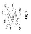
次に図7は、移植片130を送入機器具の一対のガイド部材の間に押し込んで、脊柱の隣接する椎骨の様な隣接する骨部分の間の位置に押し込むように構成された充填器具400を示している。充填器具400は、近位軸及びハンドル402と、遠位頭部404とを含んでいる。頭部404は、充填力又は押圧力を伝えるために移植片130の側壁に押し付けて配置可能な本体406を含んでいる。 Next, FIG. 7 illustrates a filling device configured to push the
頭部404は、更に、上面132の様な、移植片130のテーパー付の又は斜めに向いた上面又は下面に沿って配置可能な楔部材408を含んでいる。楔部材408は、移植片130の下面134と平行な一時的な上面を提供するが、移植片130の下面134が楔部材408の上面と平行であると言うこともできる。これにより、テーパー付の移植片130を、挿入機器具20のガイド部材70、90の様な一対の略平行なガイド部材によって、隣接する骨部分の間の空間に案内することができるようになる。楔部材408は、本体406の対応する第1側部に沿う第1側部410から、本体406の対応する第2側部に沿う第2側部に向けて傾斜した厚さを有している。楔部材408は、移植片が隣接する骨部分の間の空間に挿入される方向の軸に対して横断方向に傾斜している。楔部材408は、テーパー付移植片を、側方進入から、椎骨終板の間の角度形成が望ましい脊柱体節へ挿入することができるようになっている。 The
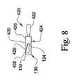
楔部材408には、斜め方向からの進入、後側方進入、前側方進入、前方進入を含め、他の進入法によるテーパー付移植片の挿入に対応できる厚さの傾斜を付けることもできる。例えば、図8は、別の実施形態の充填器具420を示しているが、これは、例えば、テーパー付移植片130を、後方進入によってガイド部材70、90の間に挿入して、隣接する椎骨の終板の間に脊椎湾曲を作り出すようになっている。充填器具420は、軸及びハンドル422と、頭部424を含んでいる。頭部424は、本体426と、本体426から遠位方向に伸張する楔部材428とを含んでいる。楔部材428は、本体426の近位端430から遠位端432まで傾斜している。楔部材428は、移植片130に、下面134と平行な一時的な上面を提供するが、逆に言うこともできる。 The
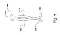
次に図9と図10は、移植片を、例えばガイド部材70、90の間へ挿入し、更に隣接する骨部分の間の空間に挿入する際に、移植片を保持するための移植片ホルダ500を示している。移植片ホルダ500は、第2アーム504に回転可能に連結された第1アーム502を有している。第2アーム504は、移植片150の様な移植片の一部を受け入れるように作られた遠位端部分506を含んでいる。同様に、第1アーム502は、移植片150の一部を受け入れるように作られた遠位端部508を含んでいる。図示の実施形態では、移植片150は、円形の外面輪郭を有し、遠位端部分506、508は、これに沿って移植片150を受け入れるように作られた凹状面輪郭を有している。移植片150をガイド部材70、90の間で前進させ易くするため、第2アーム504は、手、ハンマー又は他の器具からの嵌入力を受けるように作られた、近位伸張部510を含んでいてもよい。近位伸張部510は、第1アーム502よりも近位方向に伸張し、嵌入力をより広い面積に亘って分散させるように拡大されている。なお、アーム502、504は、どの様な形状の移植片を把持できるように作ってもよい。 Next, FIGS. 9 and 10 illustrate a graft holder for holding a graft as the graft is inserted, for example, between
ここに論じる移植片は、隣接する骨部分の融合を許容するように作られた融合移植片でもよい。この様な融合移植片には、移植片150内の骨成長材152の様な骨成長促進材及び/又は治療薬を充填してもよい。ここで論じる移植片は、椎間スペーサ、人工円板構成要素又は装置、又は隣接する骨部分の間に配置するのが望まれる他の移植片でもよい。 The grafts discussed herein may be fusion grafts made to allow fusion of adjacent bone parts. Such a fusion graft may be filled with a bone growth promoter and / or therapeutic agent, such as
ここに論じる器具は、移植片が挿入時に捩れて案内経路の外側に出るのを防ぐことによって、隣接する組織及び血管を移植片から挿入時に保護することができる。この器具は、移植片を隣接する骨部分の間の所望の位置へ挿入する時、隣接する骨部分を横切って移植片を案内する際に、骨部分を保護することもできる。実施形態では視認し易くするように作られた近位フレームを備えているので、移植片挿入の視認性が強化されている。更に、この器具は、ガイド面を略平行に維持しながら、様々な高さとテーパー角度の移植片を案内挿入し、且つ隣接する骨部分の間に様々な間隔を作り出すことができる。この器具では、ガイド部材の間の近位端開口部を通して、平行なガイド部材の間に移植片を充填することもできるようになっている。 The devices discussed herein can protect adjacent tissue and blood vessels from the graft during insertion by preventing the graft from twisting out of the guide path during insertion. The instrument can also protect the bone portion as it is guided across the adjacent bone portion when the implant is inserted into a desired location between adjacent bone portions. The embodiment includes a proximal frame made to facilitate viewing, thereby enhancing visibility of graft insertion. In addition, the instrument can guide and insert implants of various heights and taper angles while maintaining guide surfaces substantially parallel and create various spacings between adjacent bone portions. The device also allows the implant to be filled between parallel guide members through a proximal end opening between the guide members.
以上、本発明を、図面及び上記記述によって詳細に示し説明してきたが、それらは説明することを目的としており、本発明の特性に限定を加えるものではない。本発明の趣旨の範囲に入る全ての変更及び修正は、保護の対象とされるものとする。 The present invention has been shown and described in detail with reference to the drawings and the above description, but these are for the purpose of illustration and do not limit the characteristics of the present invention. All changes and modifications that fall within the spirit of the invention are intended to be protected.
Claims (48)
Translated fromJapaneseフレームを含む近位部と、
前記フレームから遠位方向に伸張する第1及び第2ガイド部材を含む遠位部と、を備えており、前記第1及び第2ガイド部材は、それぞれ、
近位端と遠位端の間に伸張している互いに反対側の第1及び第2側部と、
前記近位端から前記遠位端まで、前記第1及び第2側部の間を伸張しているガイド面と、
前記第1及び第2側部の一方だけに沿って伸張し、前記1及び第2ガイド部材の内の対応する一方のガイド部材の前記ガイド面から他方のガイド部材のガイド面に向けて突き出しているガイドフランジと、を備えている、器具。In an instrument for inserting a graft,
A proximal portion including a frame;
A distal portion including first and second guide members extending distally from the frame, wherein the first and second guide members are respectively
Opposite first and second sides extending between a proximal end and a distal end;
A guide surface extending between the first and second sides from the proximal end to the distal end;
It extends along only one of the first and second side portions, and protrudes from the guide surface of the corresponding one of the first and second guide members toward the guide surface of the other guide member. And a guide flange.
固定アームと前記固定アームに連結された可動アームとを含んでいるフレームを備えている近位部と、
前記可動アームから遠位方向に伸張している第1ガイド部材と、前記固定アームから遠位方向に伸張している第2ガイド部材とを含んでいる遠位部と、を備えており、前記第1及び第2ガイド部材は、それぞれ、前記第1及び第2ガイド部材の他方のガイド部材のガイド面の方を向いたガイド面を含んでおり、前記第1及び第2ガイド部材は、前記可動アームを前記固定アームに対して動かすことにより、互いに近づくように、及び互いに遠ざかるように動かすことができる、器具。In the instrument for inserting the instrument,
A proximal portion comprising a frame including a fixed arm and a movable arm coupled to the fixed arm;
A distal portion including a first guide member extending distally from the movable arm and a second guide member extending distally from the fixed arm; and Each of the first and second guide members includes a guide surface facing the guide surface of the other guide member of the first and second guide members, and the first and second guide members are An instrument that can be moved toward and away from each other by moving a movable arm relative to the fixed arm.
近位端と遠位端の間に伸張している互いに反対側の第1及び第2側部と、
前記近位端から前記遠位端まで、前記第1及び第2側部の間を伸張している前記ガイド面と、
前記第1及び第2側部の一方だけに沿って伸張し、前記1及び第2ガイド部材の内の対応する一方のガイド部材の前記ガイド面から他方のガイド部材のガイド面に向けて突き出しているガイドフランジと、を含んでいる、請求項19に記載の器具。The first and second guide members are respectively
Opposite first and second sides extending between a proximal end and a distal end;
The guide surface extending between the first and second sides from the proximal end to the distal end;
It extends along only one of the first and second side portions, and protrudes from the guide surface of the corresponding one of the first and second guide members toward the guide surface of the other guide member. The instrument of claim 19 including a guide flange.
第1ガイド部材と、前記第1ガイド部材に沿って伸張している第2ガイド部材とを含んでいる遠位部であって、前記第1及び第2ガイド部材は、それぞれ、前記第1及び第2ガイド部材の他方のガイド面に向いているガイド面を含んでおり、前記両ガイド面は、互いに略平行である、前記遠位部と、
前記第1及び第2ガイド部材に連結されたフレームを含んでいる近位部であって、前記フレームは、前記両ガイド面を互いに略平行に保った状態で、前記第1及び第2ガイド部材を互いに近づくように、及び互いから遠ざかるように動かせるように作られている、前記近位部と、を備えている器具。In an instrument for inserting a graft,
A distal portion including a first guide member and a second guide member extending along the first guide member, wherein the first and second guide members are the first and second guide members, respectively. The distal portion including a guide surface facing the other guide surface of the second guide member, the guide surfaces being substantially parallel to each other;
A proximal portion including a frame coupled to the first and second guide members, the frame having the guide surfaces maintained substantially parallel to each other, the first and second guide members; The proximal portion, wherein the proximal portions are configured to be movable toward and away from each other.
遠位部と近位部の間に伸張している第1部材と、
遠位部と近位部の間に伸張している第2部材とを備えており、前記第2部材は、前記第1部材に連結され、前記第1及び第2部材の前記遠位端の間に移植片を取り外し可能に把持するために前記第1部材に対して可動になっており、前記第1及び第2部材の一方の前記近位端は、前記第1及び第2部材の他方の前記近位端よりも更に近位方向に、隣接する骨部分の間の空間へ移植片を挿入し易くするための、嵌入力を受けるための嵌入ヘッドまで伸張している、器具。In an instrument for inserting a graft into the space between adjacent bone parts,
A first member extending between the distal and proximal portions;
A second member extending between the distal portion and the proximal portion, wherein the second member is coupled to the first member, and the distal ends of the first and second members are Movable relative to the first member for removably grasping the graft therebetween, wherein the proximal end of one of the first and second members is the other of the first and second members An instrument extending further into the insertion head for receiving a fitting input to facilitate insertion of the graft into a space between adjacent bone portions in a more proximal direction than the proximal end of the bone.
軸を含む近位部と、頭部を含む遠位部と、を備えており、前記頭部は、本体と楔部材とを含んでおり、前記本体は、前記本体に押し付けて配置されたテーパー付移植片に充填力を加えるための遠位端面を含んでおり、前記楔部材は、前記本体の前記端面から遠位方向に伸張しており、前記遠位端面が前記テーパー付移植片に隣接して配置されると、前記テーパー付移植片のテーパー付端面に沿って配置することができ、前記楔部材は、前記テーパー付端面に沿って、前記テーパー付移植片の前記テーパー付面とは反対側の第2面に略平行な一時的な面を形成する、器具。In an instrument for packing a tapered implant in the space between adjacent bone parts,
A proximal portion including a shaft; and a distal portion including a head portion, the head portion including a main body and a wedge member, wherein the main body is arranged to be pressed against the main body. A distal end surface for applying a filling force to the grafted graft, wherein the wedge member extends distally from the end surface of the body, the distal end surface being adjacent to the tapered graft. Arranged along the tapered end surface of the tapered graft, and the wedge member extends along the tapered end surface from the tapered surface of the tapered graft. An instrument that forms a temporary surface substantially parallel to the second surface on the opposite side.
Applications Claiming Priority (2)
| Application Number | Priority Date | Filing Date | Title |
|---|---|---|---|
| US41690802P | 2002-10-08 | 2002-10-08 | |
| PCT/US2003/031564WO2004032807A2 (en) | 2002-10-08 | 2003-10-07 | Insertion device and techniques for orthopaedic implants |
Publications (1)
| Publication Number | Publication Date |
|---|---|
| JP2006501947Atrue JP2006501947A (en) | 2006-01-19 |
Family
ID=32093920
Family Applications (1)
| Application Number | Title | Priority Date | Filing Date |
|---|---|---|---|
| JP2004543371APendingJP2006501947A (en) | 2002-10-08 | 2003-10-07 | Orthopedic graft insertion devices and techniques |
Country Status (6)
| Country | Link |
|---|---|
| US (2) | US7771432B2 (en) |
| EP (1) | EP1558184A2 (en) |
| JP (1) | JP2006501947A (en) |
| AU (1) | AU2003277287A1 (en) |
| CA (1) | CA2501437A1 (en) |
| WO (1) | WO2004032807A2 (en) |
Cited By (1)
| Publication number | Priority date | Publication date | Assignee | Title |
|---|---|---|---|---|
| JP2011519673A (en)* | 2008-05-07 | 2011-07-14 | フレイ、ジョージ、エイ. | Method and apparatus for inserting an intervertebral implant and apparatus therefor |
Families Citing this family (69)
| Publication number | Priority date | Publication date | Assignee | Title |
|---|---|---|---|---|
| EP1558184A2 (en)* | 2002-10-08 | 2005-08-03 | SDGI Holdings, Inc. | Insertion device and techniques for orthopaedic implants |
| US7625379B2 (en)* | 2004-01-26 | 2009-12-01 | Warsaw Orthopedic, Inc. | Methods and instrumentation for inserting intervertebral grafts and devices |
| US7909843B2 (en)* | 2004-06-30 | 2011-03-22 | Thompson Surgical Instruments, Inc. | Elongateable surgical port and dilator |
| US20060036261A1 (en)* | 2004-08-13 | 2006-02-16 | Stryker Spine | Insertion guide for a spinal implant |
| US20060074431A1 (en)* | 2004-09-28 | 2006-04-06 | Depuy Spine, Inc. | Disc distraction instrument and measuring device |
| WO2006058221A2 (en) | 2004-11-24 | 2006-06-01 | Abdou Samy M | Devices and methods for inter-vertebral orthopedic device placement |
| US20060241641A1 (en)* | 2005-04-22 | 2006-10-26 | Sdgi Holdings, Inc. | Methods and instrumentation for distraction and insertion of implants in a spinal disc space |
| SE528709C8 (en)* | 2005-06-01 | 2007-03-13 | Ortoviva Ab | Positioning device for a prosthetic device and system therefor |
| US8361116B2 (en)* | 2006-03-24 | 2013-01-29 | U.S. Spine, Inc. | Non-pedicle based interspinous spacer |
| US8303601B2 (en)* | 2006-06-07 | 2012-11-06 | Stryker Spine | Collet-activated distraction wedge inserter |
| US8088163B1 (en) | 2008-02-06 | 2012-01-03 | Kleiner Jeffrey B | Tools and methods for spinal fusion |
| US9060757B2 (en)* | 2008-05-05 | 2015-06-23 | Ranier Limited | Distractor |
| US20210378834A1 (en) | 2008-05-22 | 2021-12-09 | Spinal Surgical Strategies, Inc., A Nevada Corporation D/B/A Kleiner Device Labs | Spinal fusion cage system with inserter |
| USD853560S1 (en) | 2008-10-09 | 2019-07-09 | Nuvasive, Inc. | Spinal implant insertion device |
| US8864654B2 (en) | 2010-04-20 | 2014-10-21 | Jeffrey B. Kleiner | Method and apparatus for performing retro peritoneal dissection |
| US9717403B2 (en) | 2008-12-05 | 2017-08-01 | Jeffrey B. Kleiner | Method and apparatus for performing retro peritoneal dissection |
| US8366748B2 (en) | 2008-12-05 | 2013-02-05 | Kleiner Jeffrey | Apparatus and method of spinal implant and fusion |
| USD656610S1 (en) | 2009-02-06 | 2012-03-27 | Kleiner Jeffrey B | Spinal distraction instrument |
| US9247943B1 (en) | 2009-02-06 | 2016-02-02 | Kleiner Intellectual Property, Llc | Devices and methods for preparing an intervertebral workspace |
| US9351845B1 (en)* | 2009-04-16 | 2016-05-31 | Nuvasive, Inc. | Method and apparatus for performing spine surgery |
| US9173694B2 (en) | 2009-09-18 | 2015-11-03 | Spinal Surgical Strategies, Llc | Fusion cage with combined biological delivery system |
| US10973656B2 (en) | 2009-09-18 | 2021-04-13 | Spinal Surgical Strategies, Inc. | Bone graft delivery system and method for using same |
| US8685031B2 (en) | 2009-09-18 | 2014-04-01 | Spinal Surgical Strategies, Llc | Bone graft delivery system |
| US10245159B1 (en) | 2009-09-18 | 2019-04-02 | Spinal Surgical Strategies, Llc | Bone graft delivery system and method for using same |
| US8906028B2 (en) | 2009-09-18 | 2014-12-09 | Spinal Surgical Strategies, Llc | Bone graft delivery device and method of using the same |
| US9186193B2 (en) | 2009-09-18 | 2015-11-17 | Spinal Surgical Strategies, Llc | Fusion cage with combined biological delivery system |
| US20170238984A1 (en) | 2009-09-18 | 2017-08-24 | Spinal Surgical Strategies, Llc | Bone graft delivery device with positioning handle |
| US9060877B2 (en) | 2009-09-18 | 2015-06-23 | Spinal Surgical Strategies, Llc | Fusion cage with combined biological delivery system |
| USD750249S1 (en) | 2014-10-20 | 2016-02-23 | Spinal Surgical Strategies, Llc | Expandable fusion cage |
| USD723682S1 (en) | 2013-05-03 | 2015-03-03 | Spinal Surgical Strategies, Llc | Bone graft delivery tool |
| US9629729B2 (en) | 2009-09-18 | 2017-04-25 | Spinal Surgical Strategies, Llc | Biological delivery system with adaptable fusion cage interface |
| US8764806B2 (en) | 2009-12-07 | 2014-07-01 | Samy Abdou | Devices and methods for minimally invasive spinal stabilization and instrumentation |
| DE102010060101A1 (en)* | 2010-09-20 | 2012-03-22 | Aesculap Ag | Spinal stabilization system and surgical device for temporarily stiffening a flexible intermediate portion of a spinal stabilization system connector |
| US8449463B2 (en)* | 2010-10-08 | 2013-05-28 | K2M, Inc. | Lateral access system and method of use |
| WO2012083101A1 (en) | 2010-12-17 | 2012-06-21 | Synthes Usa, Llc | Methods and systems for minimally invasive posterior arch expansion |
| WO2012139022A2 (en)* | 2011-04-07 | 2012-10-11 | Kube Richard A | Interbody cage for spinal fusion and method of implanting interbody cages into spines |
| US8500749B2 (en)* | 2011-04-19 | 2013-08-06 | Prescient Surgical Designs, Llc | Apparatus and method for inserting intervertebral implants |
| US8845728B1 (en) | 2011-09-23 | 2014-09-30 | Samy Abdou | Spinal fixation devices and methods of use |
| US20130226240A1 (en) | 2012-02-22 | 2013-08-29 | Samy Abdou | Spinous process fixation devices and methods of use |
| US9198767B2 (en) | 2012-08-28 | 2015-12-01 | Samy Abdou | Devices and methods for spinal stabilization and instrumentation |
| EP2722021B1 (en)* | 2012-10-20 | 2017-12-13 | K2M, Inc. | Lateral distractor |
| AU2013245567B2 (en)* | 2012-10-22 | 2017-08-31 | K2M, Inc. | Insertion Device for Use with an Expandable Cage |
| US9320617B2 (en) | 2012-10-22 | 2016-04-26 | Cogent Spine, LLC | Devices and methods for spinal stabilization and instrumentation |
| US9351851B2 (en)* | 2012-11-09 | 2016-05-31 | Bevenue Medical, Inc. | Disc space sizing devices and methods for using the same |
| US9974588B2 (en) | 2012-12-27 | 2018-05-22 | Wright Medical Technology, Inc. | Ankle replacement system and method |
| US9480571B2 (en) | 2012-12-27 | 2016-11-01 | Wright Medical Technology, Inc. | Ankle replacement system and method |
| CA2836651C (en) | 2012-12-27 | 2016-03-22 | Wright Medical Technology, Inc. | Ankle replacement system and method |
| US9480574B2 (en) | 2013-03-14 | 2016-11-01 | Benvenue Medical, Inc. | Spinal fusion implants and devices and methods for deploying such implants |
| BR112015022274A2 (en) | 2013-03-14 | 2017-07-18 | Wright Medical Tech Inc | ankle replacement system and method |
| US10314605B2 (en) | 2014-07-08 | 2019-06-11 | Benvenue Medical, Inc. | Apparatus and methods for disrupting intervertebral disc tissue |
| US9743921B2 (en)* | 2014-09-25 | 2017-08-29 | Warsaw Orthopedic, Inc. | Spinal implant system and method |
| US10022243B2 (en) | 2015-02-06 | 2018-07-17 | Benvenue Medical, Inc. | Graft material injector system and method |
| EP3352683B1 (en)* | 2015-09-24 | 2024-02-07 | Swiss Medical Instruments AG | Distractor device |
| US10857003B1 (en) | 2015-10-14 | 2020-12-08 | Samy Abdou | Devices and methods for vertebral stabilization |
| USD797290S1 (en) | 2015-10-19 | 2017-09-12 | Spinal Surgical Strategies, Llc | Bone graft delivery tool |
| US10744000B1 (en) | 2016-10-25 | 2020-08-18 | Samy Abdou | Devices and methods for vertebral bone realignment |
| US10973648B1 (en) | 2016-10-25 | 2021-04-13 | Samy Abdou | Devices and methods for vertebral bone realignment |
| US10758286B2 (en) | 2017-03-22 | 2020-09-01 | Benvenue Medical, Inc. | Minimal impact access system to disc space |
| WO2019148083A1 (en) | 2018-01-29 | 2019-08-01 | Benvenue Medical, Inc. | Minimally invasive interbody fusion |
| US10905566B2 (en)* | 2018-02-05 | 2021-02-02 | Spineology Inc. | Percutaneous posterior implant slide |
| WO2019178575A1 (en) | 2018-03-16 | 2019-09-19 | Benvenue Medical, Inc. | Articulated instrumentation and methods of using the same |
| US11179248B2 (en) | 2018-10-02 | 2021-11-23 | Samy Abdou | Devices and methods for spinal implantation |
| USD956223S1 (en) | 2020-05-12 | 2022-06-28 | Innovasis, Inc. | Surgical retractor |
| USD956225S1 (en) | 2020-05-12 | 2022-06-28 | Innovasis, Inc. | Surgical retractor |
| USD956224S1 (en) | 2020-05-12 | 2022-06-28 | Innovasis, Inc. | Surgical retractor |
| US11432810B2 (en) | 2020-05-12 | 2022-09-06 | Innovasis, Inc. | Systems and methods for surgical retraction |
| WO2022250665A1 (en)* | 2021-05-26 | 2022-12-01 | James Carr | Spinal retractor blade and related retractor device |
| US20240350130A1 (en)* | 2023-04-19 | 2024-10-24 | Life Spine, Inc. | Micro Retractor |
| WO2025137288A1 (en)* | 2023-12-19 | 2025-06-26 | Amplify Surgical, Inc. | Spinal implant delivery device for protecting tissue |
Family Cites Families (79)
| Publication number | Priority date | Publication date | Assignee | Title |
|---|---|---|---|---|
| US424140A (en)* | 1890-03-25 | Anal speculum | ||
| US663638A (en)* | 1899-02-28 | 1900-12-11 | Heinrich Poetter | Coke-oven. |
| US3486505A (en)* | 1967-05-22 | 1969-12-30 | Gordon M Morrison | Orthopedic surgical instrument |
| BE757681A (en)* | 1970-01-22 | 1971-04-01 | Sampson Arnold | IMPROVEMENTS TO DENTAL PROSTHESIS DEVICES |
| US3848601A (en) | 1972-06-14 | 1974-11-19 | G Ma | Method for interbody fusion of the spine |
| US4165746A (en)* | 1977-06-30 | 1979-08-28 | Burgin Kermit H | Plastic forceps |
| US4386603A (en) | 1981-03-23 | 1983-06-07 | Mayfield Jack K | Distraction device for spinal distraction systems |
| US4736738A (en) | 1984-07-09 | 1988-04-12 | Matej Lipovsek | Instrument kit and procedure for performing posterior lumbar interbody fusion |
| US4677798A (en)* | 1986-04-14 | 1987-07-07 | Phillips Edward H | Steel shell modules for prisoner detention facilities |
| US4747588A (en)* | 1986-08-15 | 1988-05-31 | Dillhoff George A | Universal clamping tool |
| US4758159A (en)* | 1986-10-06 | 1988-07-19 | Ipco Corporation | Adjustable mandrel |
| DE3707097A1 (en) | 1986-12-05 | 1988-06-09 | S & G Implants Gmbh | PLIERS FOR SPREADING SPINE BODIES |
| DE3809793A1 (en) | 1988-03-23 | 1989-10-05 | Link Waldemar Gmbh Co | SURGICAL INSTRUMENT SET |
| EP0703757B1 (en) | 1988-06-13 | 2003-08-27 | Karlin Technology, Inc. | Apparatus for inserting spinal implants |
| US5484437A (en) | 1988-06-13 | 1996-01-16 | Michelson; Gary K. | Apparatus and method of inserting spinal implants |
| CA1333209C (en) | 1988-06-28 | 1994-11-29 | Gary Karlin Michelson | Artificial spinal fusion implants |
| US5052373A (en)* | 1988-07-29 | 1991-10-01 | Michelson Gary K | Spinal retractor |
| US4955885A (en) | 1988-12-21 | 1990-09-11 | Zimmer, Inc. | Surgical slider instrument and method of using instrument |
| US5088472A (en)* | 1990-04-04 | 1992-02-18 | Mehdi Fakhrai | Retractor |
| US5192327A (en) | 1991-03-22 | 1993-03-09 | Brantigan John W | Surgical prosthetic implant for vertebrae |
| US5199419A (en) | 1991-08-05 | 1993-04-06 | United States Surgical Corporation | Surgical retractor |
| US5235966A (en) | 1991-10-17 | 1993-08-17 | Jay Jamner | Endoscopic retractor |
| DE4328690B4 (en)* | 1993-08-26 | 2006-08-17 | SDGI Holdings, Inc., Wilmington | Intervertebral implant for vertebral body blocking and implantation instrument for positioning the intervertebral implant |
| WO1995010238A1 (en)* | 1993-10-08 | 1995-04-20 | Chaim Rogozinski | Spinal treatment apparatus and method including multi-directional attachment member |
| US5431658A (en) | 1994-02-14 | 1995-07-11 | Moskovich; Ronald | Facilitator for vertebrae grafts and prostheses |
| CA2144211C (en) | 1994-03-16 | 2005-05-24 | David T. Green | Surgical instruments useful for endoscopic spinal procedures |
| US6245072B1 (en) | 1995-03-27 | 2001-06-12 | Sdgi Holdings, Inc. | Methods and instruments for interbody fusion |
| US5616117A (en)* | 1995-08-03 | 1997-04-01 | Ohio Medical Instrument Company, Inc. | Self locking surgical retractor |
| DE19529605C2 (en) | 1995-08-11 | 1997-10-09 | Bernhard Zientek | Intervertebral implant |
| US5722977A (en) | 1996-01-24 | 1998-03-03 | Danek Medical, Inc. | Method and means for anterior lumbar exact cut with quadrilateral osteotome and precision guide/spacer |
| CA2199462C (en) | 1996-03-14 | 2006-01-03 | Charles J. Winslow | Method and instrumentation for implant insertion |
| JP3258615B2 (en)* | 1996-11-15 | 2002-02-18 | キヤノン株式会社 | Communication system and control method thereof |
| DE29703850U1 (en)* | 1997-03-03 | 1997-04-24 | Aesculap Ag, 78532 Tuttlingen | Detachable holder for a sheet on the arm of a surgical retractor |
| US5897556A (en) | 1997-06-02 | 1999-04-27 | Sdgi Holdings, Inc. | Device for supporting weak bony structures |
| US6004326A (en) | 1997-09-10 | 1999-12-21 | United States Surgical | Method and instrumentation for implant insertion |
| US5944658A (en) | 1997-09-23 | 1999-08-31 | Koros; Tibor B. | Lumbar spinal fusion retractor and distractor system |
| US6159215A (en) | 1997-12-19 | 2000-12-12 | Depuy Acromed, Inc. | Insertion instruments and method for delivering a vertebral body spacer |
| US6083228A (en) | 1998-06-09 | 2000-07-04 | Michelson; Gary K. | Device and method for preparing a space between adjacent vertebrae to receive an insert |
| US6139493A (en)* | 1998-07-08 | 2000-10-31 | Koros; Tibor B. | Retractor with adjustable length blades and light pipe guides |
| AU760821B2 (en) | 1998-10-02 | 2003-05-22 | Synthes Gmbh | Spinal disc space distractor |
| US6174311B1 (en) | 1998-10-28 | 2001-01-16 | Sdgi Holdings, Inc. | Interbody fusion grafts and instrumentation |
| ATE464847T1 (en) | 1999-01-25 | 2010-05-15 | Warsaw Orthopedic Inc | INSTRUMENT FOR CREATION OF AN INTERVERBEL SPACE FOR ACCOMMODATION OF AN IMPLANT |
| DE19903762C1 (en)* | 1999-01-30 | 2000-11-16 | Aesculap Ag & Co Kg | Surgical instrument for inserting intervertebral implants |
| AU761818C (en) | 1999-02-04 | 2004-05-27 | Warsaw Orthopedic, Inc. | Methods and instrumentation for vertebral interbody fusion |
| US6332887B1 (en) | 1999-04-06 | 2001-12-25 | Benjamin D. Knox | Spinal fusion instrumentation system |
| US6224599B1 (en) | 1999-05-19 | 2001-05-01 | Matthew G. Baynham | Viewable wedge distractor device |
| EP1792586B1 (en) | 1999-09-14 | 2012-12-26 | Spine Solutions Inc. | Insert instrument for an implant between vertebrae |
| US6436101B1 (en) | 1999-10-13 | 2002-08-20 | James S. Hamada | Rasp for use in spine surgery |
| US6830570B1 (en)* | 1999-10-21 | 2004-12-14 | Sdgi Holdings, Inc. | Devices and techniques for a posterior lateral disc space approach |
| US6395034B1 (en) | 1999-11-24 | 2002-05-28 | Loubert Suddaby | Intervertebral disc prosthesis |
| WO2001041681A1 (en)* | 1999-12-10 | 2001-06-14 | Nuvasive, Inc. | Facet screw and bone allograft intervertebral support and fusion system |
| US6558390B2 (en)* | 2000-02-16 | 2003-05-06 | Axiamed, Inc. | Methods and apparatus for performing therapeutic procedures in the spine |
| ATE390100T1 (en) | 2000-02-22 | 2008-04-15 | Warsaw Orthopedic Inc | SPINAL IMPLANT AND INTRODUCTION DEVICE |
| US6514260B1 (en) | 2000-03-15 | 2003-02-04 | Sdgi Holdings, Inc. | Methods and instruments for laparoscopic spinal surgery |
| AU2001259593A1 (en) | 2000-05-05 | 2001-11-20 | Osteotech, Inc. | Intervertebral distractor and implant insertion instrument |
| US6478800B1 (en) | 2000-05-08 | 2002-11-12 | Depuy Acromed, Inc. | Medical installation tool |
| US7018416B2 (en) | 2000-07-06 | 2006-03-28 | Zimmer Spine, Inc. | Bone implants and methods |
| US6641582B1 (en) | 2000-07-06 | 2003-11-04 | Sulzer Spine-Tech Inc. | Bone preparation instruments and methods |
| DE10065232C2 (en) | 2000-12-27 | 2002-11-14 | Ulrich Gmbh & Co Kg | Implant for insertion between the vertebral body and surgical instrument for handling the implant |
| AU2002235351A1 (en)* | 2001-01-26 | 2002-08-06 | Osteotech, Inc. | Implant insertion tool |
| DE60224850T2 (en) | 2001-02-04 | 2009-01-22 | Warsaw Orthopedic, Inc., Warsaw | Instrumentation for introducing and positioning an expandable intervertebral fusion implant |
| US7115132B2 (en) | 2001-07-16 | 2006-10-03 | Spinecore, Inc. | Static trials and related instruments and methods for use in implanting an artificial intervertebral disc |
| US7169182B2 (en) | 2001-07-16 | 2007-01-30 | Spinecore, Inc. | Implanting an artificial intervertebral disc |
| US7575576B2 (en) | 2001-07-16 | 2009-08-18 | Spinecore, Inc. | Wedge ramp distractor and related methods for use in implanting artificial intervertebral discs |
| US7235081B2 (en) | 2001-07-16 | 2007-06-26 | Spinecore, Inc. | Wedge plate inserter/impactor and related methods for use in implanting an artificial intervertebral disc |
| US20020138078A1 (en) | 2001-03-21 | 2002-09-26 | Chappuis James L. | System and method for cutting grafts |
| US6440142B1 (en) | 2001-04-27 | 2002-08-27 | Third Millennium Engineering, Llc | Femoral ring loader |
| US20030149438A1 (en) | 2001-04-30 | 2003-08-07 | Howmedica Osteonics Corp. | Insertion instrument |
| US6585749B2 (en) | 2001-08-01 | 2003-07-01 | Sulzer Spine-Tech Inc. | Surgical implant instrument and method |
| US20030045884A1 (en) | 2001-09-04 | 2003-03-06 | Bruce Robie | Instrument and system for preparing the disc space between two vertebral bodies |
| WO2003024344A1 (en) | 2001-09-14 | 2003-03-27 | The Regents Of The University Of California | System and method for fusing spinal vertebrae |
| US6652533B2 (en) | 2001-09-20 | 2003-11-25 | Depuy Acromed, Inc. | Medical inserter tool with slaphammer |
| US6840941B2 (en) | 2001-10-31 | 2005-01-11 | Depuy Acromed, Inc. | Vertebral endplate chisel |
| EP1482877B1 (en) | 2002-03-11 | 2007-05-30 | Spinal Concepts Inc. | Instrumentation for implanting spinal implant devices |
| US7169153B2 (en) | 2002-06-10 | 2007-01-30 | Depuy Spine | Surgical instrument for inserting intervertebral prosthesis |
| US20040024291A1 (en) | 2002-08-01 | 2004-02-05 | Zinkel John L. | Method and apparatus for spinal surgery |
| EP1558184A2 (en) | 2002-10-08 | 2005-08-03 | SDGI Holdings, Inc. | Insertion device and techniques for orthopaedic implants |
| AU2003295934B2 (en)* | 2002-11-23 | 2009-02-26 | Frey, George A. | Distraction and retraction system for spinal surgery |
| US20050021040A1 (en) | 2003-07-21 | 2005-01-27 | Rudolf Bertagnoli | Vertebral retainer-distracter and method of using same |
- 2003
- 2003-10-07EPEP03808146Apatent/EP1558184A2/ennot_activeWithdrawn
- 2003-10-07WOPCT/US2003/031564patent/WO2004032807A2/enactiveApplication Filing
- 2003-10-07JPJP2004543371Apatent/JP2006501947A/enactivePending
- 2003-10-07USUS10/680,358patent/US7771432B2/enactiveActive
- 2003-10-07CACA002501437Apatent/CA2501437A1/ennot_activeAbandoned
- 2003-10-07AUAU2003277287Apatent/AU2003277287A1/ennot_activeAbandoned
- 2010
- 2010-05-07USUS12/800,065patent/US7951154B2/ennot_activeExpired - Fee Related
Cited By (1)
| Publication number | Priority date | Publication date | Assignee | Title |
|---|---|---|---|---|
| JP2011519673A (en)* | 2008-05-07 | 2011-07-14 | フレイ、ジョージ、エイ. | Method and apparatus for inserting an intervertebral implant and apparatus therefor |
Also Published As
| Publication number | Publication date |
|---|---|
| US20050075643A1 (en) | 2005-04-07 |
| US7771432B2 (en) | 2010-08-10 |
| WO2004032807A2 (en) | 2004-04-22 |
| CA2501437A1 (en) | 2004-04-22 |
| WO2004032807A3 (en) | 2004-09-23 |
| AU2003277287A1 (en) | 2004-05-04 |
| EP1558184A2 (en) | 2005-08-03 |
| US20100222784A1 (en) | 2010-09-02 |
| US7951154B2 (en) | 2011-05-31 |
Similar Documents
| Publication | Publication Date | Title |
|---|---|---|
| JP2006501947A (en) | Orthopedic graft insertion devices and techniques | |
| US11857438B2 (en) | Methods and apparatus for intervertebral disc prosthesis insertion | |
| US6652533B2 (en) | Medical inserter tool with slaphammer | |
| US8002837B2 (en) | Spinal stabilization device and methods | |
| TWI422352B (en) | Interlaminar-interspinous vertebral stabilization system | |
| KR101358560B1 (en) | Transforaminal intersomatic cage and an instrument for implanting the cage | |
| US8267997B2 (en) | Vertebral interbody compression implant | |
| US6558424B2 (en) | Modular anatomic fusion device | |
| US20080306598A1 (en) | Spinal implant with biologic sponge | |
| US20080065082A1 (en) | Steerable rasp/trial inserter | |
| US20070233153A1 (en) | Instrumentation for distraction and insertion of implants in a spinal disc space | |
| CA2553534A1 (en) | Methods and instrumentation for inserting intervertebral grafts and devices | |
| AU2005314224A1 (en) | Method for replacing a spinal disc | |
| JP2009534130A (en) | Monorail system | |
| US11497615B2 (en) | Cervical disc and instrumentation |
Legal Events
| Date | Code | Title | Description |
|---|---|---|---|
| A621 | Written request for application examination | Free format text:JAPANESE INTERMEDIATE CODE: A621 Effective date:20060510 | |
| A711 | Notification of change in applicant | Free format text:JAPANESE INTERMEDIATE CODE: A712 Effective date:20061011 | |
| A131 | Notification of reasons for refusal | Free format text:JAPANESE INTERMEDIATE CODE: A131 Effective date:20090410 | |
| A02 | Decision of refusal | Free format text:JAPANESE INTERMEDIATE CODE: A02 Effective date:20091005 |