JP2006501056A - Micro fluid large scale integration - Google Patents
Micro fluid large scale integrationDownload PDFInfo
- Publication number
- JP2006501056A JP2006501056AJP2004539937AJP2004539937AJP2006501056AJP 2006501056 AJP2006501056 AJP 2006501056AJP 2004539937 AJP2004539937 AJP 2004539937AJP 2004539937 AJP2004539937 AJP 2004539937AJP 2006501056 AJP2006501056 AJP 2006501056A
- Authority
- JP
- Japan
- Prior art keywords
- flow
- control channel
- microfluidic
- flow channel
- network
- Prior art date
- Legal status (The legal status is an assumption and is not a legal conclusion. Google has not performed a legal analysis and makes no representation as to the accuracy of the status listed.)
- Pending
Links
- 239000012530fluidSubstances0.000titleclaimsabstractdescription106
- 230000010354integrationEffects0.000titleabstractdescription6
- 238000000034methodMethods0.000claimsabstractdescription94
- 229920001971elastomerPolymers0.000claimsdescription157
- 239000000806elastomerSubstances0.000claimsdescription157
- 239000012528membraneSubstances0.000claimsdescription95
- 238000003860storageMethods0.000claimsdescription45
- 239000000463materialSubstances0.000claimsdescription32
- 239000013536elastomeric materialSubstances0.000claimsdescription20
- 230000006870functionEffects0.000claimsdescription20
- 238000004891communicationMethods0.000claimsdescription17
- 239000000126substanceSubstances0.000claimsdescription15
- 238000003825pressingMethods0.000claimsdescription13
- 230000033001locomotionEffects0.000claimsdescription4
- 239000000376reactantSubstances0.000claimsdescription3
- 230000003213activating effectEffects0.000claimsdescription2
- 239000003795chemical substances by applicationSubstances0.000claims2
- 238000007865dilutingMethods0.000claims1
- 230000001131transforming effectEffects0.000claims1
- 230000015654memoryEffects0.000abstractdescription10
- 230000005055memory storageEffects0.000abstractdescription8
- 238000003491arrayMethods0.000abstractdescription5
- 210000004027cellAnatomy0.000description33
- 239000000758substrateSubstances0.000description33
- 238000003556assayMethods0.000description28
- 239000000203mixtureSubstances0.000description27
- 238000004519manufacturing processMethods0.000description23
- 230000004888barrier functionEffects0.000description21
- 229920000642polymerPolymers0.000description20
- 239000000523sampleSubstances0.000description20
- 230000008901benefitEffects0.000description18
- 238000010926purgeMethods0.000description18
- 238000011068loading methodMethods0.000description16
- 238000002156mixingMethods0.000description15
- 108090000623proteins and genesProteins0.000description15
- 239000008241heterogeneous mixtureSubstances0.000description14
- 230000004044responseEffects0.000description14
- 108060006006Cytochrome-c peroxidaseProteins0.000description13
- 238000013461designMethods0.000description13
- 239000007788liquidSubstances0.000description13
- 230000002572peristaltic effectEffects0.000description13
- 238000006243chemical reactionMethods0.000description12
- 239000000243solutionSubstances0.000description12
- 239000010408filmSubstances0.000description11
- 229920002120photoresistant polymerPolymers0.000description11
- 229920001296polysiloxanePolymers0.000description11
- 108020004414DNAProteins0.000description10
- 230000000694effectsEffects0.000description10
- 239000007789gasSubstances0.000description10
- 230000008569processEffects0.000description10
- 102000004169proteins and genesHuman genes0.000description10
- WYTGDNHDOZPMIW-RCBQFDQVSA-NalstonineNatural productsC1=CC2=C3C=CC=CC3=NC2=C2N1C[C@H]1[C@H](C)OC=C(C(=O)OC)[C@H]1C2WYTGDNHDOZPMIW-RCBQFDQVSA-N0.000description9
- 239000011521glassSubstances0.000description9
- 229920000435poly(dimethylsiloxane)Polymers0.000description9
- 239000000047productSubstances0.000description9
- 108090000790EnzymesProteins0.000description8
- 102000004190EnzymesHuman genes0.000description8
- 238000012864cross contaminationMethods0.000description8
- 238000010586diagramMethods0.000description8
- 239000002245particleSubstances0.000description8
- 241000894006BacteriaSpecies0.000description7
- 230000008859changeEffects0.000description7
- 239000004205dimethyl polysiloxaneSubstances0.000description7
- 238000002474experimental methodMethods0.000description7
- 238000001080multi-layer soft lithographyMethods0.000description7
- 230000002829reductive effectEffects0.000description7
- 241000588724Escherichia coliSpecies0.000description6
- 238000013459approachMethods0.000description6
- 230000001276controlling effectEffects0.000description6
- 108010048367enhanced green fluorescent proteinProteins0.000description6
- 230000007246mechanismEffects0.000description6
- XLYOFNOQVPJJNP-UHFFFAOYSA-NwaterSubstancesOXLYOFNOQVPJJNP-UHFFFAOYSA-N0.000description6
- 239000000872bufferSubstances0.000description5
- 239000000975dyeSubstances0.000description5
- 238000005516engineering processMethods0.000description5
- 239000007850fluorescent dyeSubstances0.000description5
- 238000000879optical micrographMethods0.000description5
- 238000000926separation methodMethods0.000description5
- 229920002379silicone rubberPolymers0.000description5
- 229920000468styrene butadiene styrene block copolymerPolymers0.000description5
- PKYCWFICOKSIHZ-UHFFFAOYSA-N1-(3,7-dihydroxyphenoxazin-10-yl)ethanoneChemical compoundOC1=CC=C2N(C(=O)C)C3=CC=C(O)C=C3OC2=C1PKYCWFICOKSIHZ-UHFFFAOYSA-N0.000description4
- KAKZBPTYRLMSJV-UHFFFAOYSA-NButadieneChemical compoundC=CC=CKAKZBPTYRLMSJV-UHFFFAOYSA-N0.000description4
- RRHGJUQNOFWUDK-UHFFFAOYSA-NIsopreneChemical compoundCC(=C)C=CRRHGJUQNOFWUDK-UHFFFAOYSA-N0.000description4
- 229920002367PolyisobutenePolymers0.000description4
- BLRPTPMANUNPDV-UHFFFAOYSA-NSilaneChemical compound[SiH4]BLRPTPMANUNPDV-UHFFFAOYSA-N0.000description4
- 239000011324beadSubstances0.000description4
- 150000005829chemical entitiesChemical class0.000description4
- IJOOHPMOJXWVHK-UHFFFAOYSA-NchlorotrimethylsilaneChemical compoundC[Si](C)(C)ClIJOOHPMOJXWVHK-UHFFFAOYSA-N0.000description4
- 239000006059cover glassSubstances0.000description4
- 238000005538encapsulationMethods0.000description4
- 239000005090green fluorescent proteinSubstances0.000description4
- 239000000178monomerSubstances0.000description4
- 230000003287optical effectEffects0.000description4
- 238000005192partitionMethods0.000description4
- 238000003752polymerase chain reactionMethods0.000description4
- 229920002635polyurethanePolymers0.000description4
- 239000004814polyurethaneSubstances0.000description4
- 108090000765processed proteins & peptidesProteins0.000description4
- HSSLDCABUXLXKM-UHFFFAOYSA-NresorufinChemical compoundC1=CC(=O)C=C2OC3=CC(O)=CC=C3N=C21HSSLDCABUXLXKM-UHFFFAOYSA-N0.000description4
- 230000002441reversible effectEffects0.000description4
- 150000003384small moleculesChemical class0.000description4
- 230000007306turnoverEffects0.000description4
- KFZMGEQAYNKOFK-UHFFFAOYSA-NIsopropanolChemical compoundCC(C)OKFZMGEQAYNKOFK-UHFFFAOYSA-N0.000description3
- 108091028043Nucleic acid sequenceProteins0.000description3
- 239000005062PolybutadieneSubstances0.000description3
- XUIMIQQOPSSXEZ-UHFFFAOYSA-NSiliconChemical compound[Si]XUIMIQQOPSSXEZ-UHFFFAOYSA-N0.000description3
- FACXGONDLDSNOE-UHFFFAOYSA-Nbuta-1,3-diene;styreneChemical compoundC=CC=C.C=CC1=CC=CC=C1.C=CC1=CC=CC=C1FACXGONDLDSNOE-UHFFFAOYSA-N0.000description3
- 239000003054catalystSubstances0.000description3
- 239000002299complementary DNASubstances0.000description3
- 238000001723curingMethods0.000description3
- LOKCTEFSRHRXRJ-UHFFFAOYSA-Idipotassium trisodium dihydrogen phosphate hydrogen phosphate dichlorideChemical compoundP(=O)(O)(O)[O-].[K+].P(=O)(O)([O-])[O-].[Na+].[Na+].[Cl-].[K+].[Cl-].[Na+]LOKCTEFSRHRXRJ-UHFFFAOYSA-I0.000description3
- 210000003527eukaryotic cellAnatomy0.000description3
- 238000009472formulationMethods0.000description3
- 238000010438heat treatmentMethods0.000description3
- 238000007689inspectionMethods0.000description3
- 238000002955isolationMethods0.000description3
- 239000011159matrix materialSubstances0.000description3
- 238000005259measurementMethods0.000description3
- 238000012986modificationMethods0.000description3
- 230000004048modificationEffects0.000description3
- UPSFMJHZUCSEHU-JYGUBCOQSA-Nn-[(2s,3r,4r,5s,6r)-2-[(2r,3s,4r,5r,6s)-5-acetamido-4-hydroxy-2-(hydroxymethyl)-6-(4-methyl-2-oxochromen-7-yl)oxyoxan-3-yl]oxy-4,5-dihydroxy-6-(hydroxymethyl)oxan-3-yl]acetamideChemical compoundCC(=O)N[C@@H]1[C@@H](O)[C@H](O)[C@@H](CO)O[C@H]1O[C@H]1[C@H](O)[C@@H](NC(C)=O)[C@H](OC=2C=C3OC(=O)C=C(C)C3=CC=2)O[C@@H]1COUPSFMJHZUCSEHU-JYGUBCOQSA-N0.000description3
- 239000002953phosphate buffered salineSubstances0.000description3
- 229920001084poly(chloroprene)Polymers0.000description3
- 229920002857polybutadienePolymers0.000description3
- -1polydimethylsiloxanePolymers0.000description3
- 229920001195polyisoprenePolymers0.000description3
- 238000011084recoveryMethods0.000description3
- 230000011218segmentationEffects0.000description3
- 229910052710siliconInorganic materials0.000description3
- 239000010703siliconSubstances0.000description3
- 239000004945silicone rubberSubstances0.000description3
- 238000004528spin coatingMethods0.000description3
- 229920001187thermosetting polymerPolymers0.000description3
- JOYRKODLDBILNP-UHFFFAOYSA-NEthyl urethaneChemical compoundCCOC(N)=OJOYRKODLDBILNP-UHFFFAOYSA-N0.000description2
- 239000004696Poly ether ether ketoneSubstances0.000description2
- FAPWRFPIFSIZLT-UHFFFAOYSA-MSodium chlorideChemical compound[Na+].[Cl-]FAPWRFPIFSIZLT-UHFFFAOYSA-M0.000description2
- 241000700605VirusesSpecies0.000description2
- 230000009471actionEffects0.000description2
- 239000000853adhesiveSubstances0.000description2
- 230000001070adhesive effectEffects0.000description2
- 230000003321amplificationEffects0.000description2
- 238000004458analytical methodMethods0.000description2
- 238000000376autoradiographyMethods0.000description2
- 210000003050axonAnatomy0.000description2
- 230000000903blocking effectEffects0.000description2
- 239000003153chemical reaction reagentSubstances0.000description2
- 239000003593chromogenic compoundSubstances0.000description2
- 238000004132cross linkingMethods0.000description2
- 230000007423decreaseEffects0.000description2
- 230000001419dependent effectEffects0.000description2
- 238000011161developmentMethods0.000description2
- 230000018109developmental processEffects0.000description2
- 150000004985diaminesChemical class0.000description2
- 125000005442diisocyanate groupChemical group0.000description2
- 239000002019doping agentSubstances0.000description2
- 238000001704evaporationMethods0.000description2
- 230000008020evaporationEffects0.000description2
- 230000005284excitationEffects0.000description2
- MHMNJMPURVTYEJ-UHFFFAOYSA-Nfluorescein-5-isothiocyanateChemical compoundO1C(=O)C2=CC(N=C=S)=CC=C2C21C1=CC=C(O)C=C1OC1=CC(O)=CC=C21MHMNJMPURVTYEJ-UHFFFAOYSA-N0.000description2
- 238000002073fluorescence micrographMethods0.000description2
- 125000000524functional groupChemical group0.000description2
- 238000013537high throughput screeningMethods0.000description2
- 239000012456homogeneous solutionSubstances0.000description2
- 238000000338in vitroMethods0.000description2
- 238000010348incorporationMethods0.000description2
- 238000001746injection mouldingMethods0.000description2
- 108020004999messenger RNAProteins0.000description2
- 229910052751metalInorganic materials0.000description2
- 239000002184metalSubstances0.000description2
- 239000012299nitrogen atmosphereSubstances0.000description2
- 238000003199nucleic acid amplification methodMethods0.000description2
- 108020004707nucleic acidsProteins0.000description2
- 102000039446nucleic acidsHuman genes0.000description2
- 150000007523nucleic acidsChemical class0.000description2
- 230000002093peripheral effectEffects0.000description2
- 230000035699permeabilityEffects0.000description2
- 238000000206photolithographyMethods0.000description2
- 230000000704physical effectEffects0.000description2
- 239000004033plasticSubstances0.000description2
- 229920003023plasticPolymers0.000description2
- 229920002530polyetherether ketonePolymers0.000description2
- 210000001236prokaryotic cellAnatomy0.000description2
- 238000000159protein binding assayMethods0.000description2
- 230000001105regulatory effectEffects0.000description2
- 238000011160researchMethods0.000description2
- 239000012266salt solutionSubstances0.000description2
- 238000012216screeningMethods0.000description2
- 229910052990silicon hydrideInorganic materials0.000description2
- 229920005573silicon-containing polymerPolymers0.000description2
- 238000000638solvent extractionMethods0.000description2
- 241000894007speciesSpecies0.000description2
- 230000004083survival effectEffects0.000description2
- 238000013518transcriptionMethods0.000description2
- 230000035897transcriptionEffects0.000description2
- 238000013519translationMethods0.000description2
- 239000005051trimethylchlorosilaneSubstances0.000description2
- 125000000391vinyl groupChemical group[H]C([*])=C([H])[H]0.000description2
- 238000004073vulcanizationMethods0.000description2
- 108091093088AmpliconProteins0.000description1
- 239000004971Cross linkerSubstances0.000description1
- 238000000018DNA microarrayMethods0.000description1
- 239000003298DNA probeSubstances0.000description1
- 241000408659DarpaSpecies0.000description1
- 238000002965ELISAMethods0.000description1
- 206010061217InfestationDiseases0.000description1
- 239000007836KH2PO4Substances0.000description1
- 108010067902Peptide LibraryProteins0.000description1
- 102000007056Recombinant Fusion ProteinsHuman genes0.000description1
- 108010008281Recombinant Fusion ProteinsProteins0.000description1
- 229910000831SteelInorganic materials0.000description1
- NINIDFKCEFEMDL-UHFFFAOYSA-NSulfurChemical compound[S]NINIDFKCEFEMDL-UHFFFAOYSA-N0.000description1
- 230000004913activationEffects0.000description1
- 239000008186active pharmaceutical agentSubstances0.000description1
- 238000013006addition curingMethods0.000description1
- 239000000654additiveSubstances0.000description1
- 125000001931aliphatic groupChemical group0.000description1
- 239000007864aqueous solutionSubstances0.000description1
- QVGXLLKOCUKJST-UHFFFAOYSA-Natomic oxygenChemical compound[O]QVGXLLKOCUKJST-UHFFFAOYSA-N0.000description1
- 229910002056binary alloyInorganic materials0.000description1
- 238000004166bioassayMethods0.000description1
- 239000012620biological materialSubstances0.000description1
- 230000005540biological transmissionEffects0.000description1
- 230000015572biosynthetic processEffects0.000description1
- 230000036772blood pressureEffects0.000description1
- UDSAIICHUKSCKT-UHFFFAOYSA-Nbromophenol blueChemical compoundC1=C(Br)C(O)=C(Br)C=C1C1(C=2C=C(Br)C(O)=C(Br)C=2)C2=CC=CC=C2S(=O)(=O)O1UDSAIICHUKSCKT-UHFFFAOYSA-N0.000description1
- 239000003990capacitorSubstances0.000description1
- 230000021164cell adhesionEffects0.000description1
- 210000001175cerebrospinal fluidAnatomy0.000description1
- 238000003486chemical etchingMethods0.000description1
- 238000007385chemical modificationMethods0.000description1
- 239000013626chemical specieSubstances0.000description1
- 210000000349chromosomeAnatomy0.000description1
- 230000003750conditioning effectEffects0.000description1
- 238000011109contaminationMethods0.000description1
- 229920001577copolymerPolymers0.000description1
- 239000007822coupling agentSubstances0.000description1
- 238000002425crystallisationMethods0.000description1
- 230000008025crystallizationEffects0.000description1
- 230000003247decreasing effectEffects0.000description1
- 230000007812deficiencyEffects0.000description1
- 238000002405diagnostic procedureMethods0.000description1
- 150000001993dienesChemical class0.000description1
- 238000009792diffusion processMethods0.000description1
- 238000010790dilutionMethods0.000description1
- 239000012895dilutionSubstances0.000description1
- 229910000397disodium phosphateInorganic materials0.000description1
- 238000006073displacement reactionMethods0.000description1
- 238000009826distributionMethods0.000description1
- 238000000609electron-beam lithographyMethods0.000description1
- 230000009088enzymatic functionEffects0.000description1
- 238000006911enzymatic reactionMethods0.000description1
- 238000001952enzyme assayMethods0.000description1
- JZMPIUODFXBXSC-UHFFFAOYSA-Nethyl carbamate;prop-2-enoic acidChemical compoundOC(=O)C=C.OC(=O)C=C.CCOC(N)=OJZMPIUODFXBXSC-UHFFFAOYSA-N0.000description1
- 238000011049fillingMethods0.000description1
- 239000012467final productSubstances0.000description1
- 238000000799fluorescence microscopyMethods0.000description1
- 238000002866fluorescence resonance energy transferMethods0.000description1
- 239000000989food dyeSubstances0.000description1
- 230000004927fusionEffects0.000description1
- 230000002496gastric effectEffects0.000description1
- 229910052732germaniumInorganic materials0.000description1
- GNPVGFCGXDBREM-UHFFFAOYSA-Ngermanium atomChemical compound[Ge]GNPVGFCGXDBREM-UHFFFAOYSA-N0.000description1
- 230000009477glass transitionEffects0.000description1
- PCHJSUWPFVWCPO-UHFFFAOYSA-NgoldChemical compound[Au]PCHJSUWPFVWCPO-UHFFFAOYSA-N0.000description1
- 239000010931goldSubstances0.000description1
- 229910052737goldInorganic materials0.000description1
- 230000012010growthEffects0.000description1
- 239000008240homogeneous mixtureSubstances0.000description1
- 210000004408hybridomaAnatomy0.000description1
- 238000007654immersionMethods0.000description1
- 238000011065in-situ storageMethods0.000description1
- 238000011534incubationMethods0.000description1
- 230000002427irreversible effectEffects0.000description1
- 238000011005laboratory methodMethods0.000description1
- 238000003698laser cuttingMethods0.000description1
- 230000000670limiting effectEffects0.000description1
- 238000010551living anionic polymerization reactionMethods0.000description1
- 238000013178mathematical modelMethods0.000description1
- 239000000155meltSubstances0.000description1
- QSHDDOUJBYECFT-UHFFFAOYSA-NmercuryChemical compound[Hg]QSHDDOUJBYECFT-UHFFFAOYSA-N0.000description1
- 229910052753mercuryInorganic materials0.000description1
- 150000002739metalsChemical class0.000description1
- 238000002493microarrayMethods0.000description1
- 238000000386microscopyMethods0.000description1
- 229910000402monopotassium phosphateInorganic materials0.000description1
- 235000019796monopotassium phosphateNutrition0.000description1
- 210000003205muscleAnatomy0.000description1
- 239000013642negative controlSubstances0.000description1
- 239000012454non-polar solventSubstances0.000description1
- 239000003921oilSubstances0.000description1
- 238000005457optimizationMethods0.000description1
- 239000003960organic solventSubstances0.000description1
- 239000001301oxygenSubstances0.000description1
- 229910052760oxygenInorganic materials0.000description1
- 238000000059patterningMethods0.000description1
- 230000008855peristalsisEffects0.000description1
- 230000002186photoactivationEffects0.000description1
- 208000017983photosensitivity diseaseDiseases0.000description1
- 231100000434photosensitizationToxicity0.000description1
- 239000013612plasmidSubstances0.000description1
- 238000006116polymerization reactionMethods0.000description1
- GNSKLFRGEWLPPA-UHFFFAOYSA-Mpotassium dihydrogen phosphateChemical compound[K+].OP(O)([O-])=OGNSKLFRGEWLPPA-UHFFFAOYSA-M0.000description1
- 239000002243precursorSubstances0.000description1
- 102000004196processed proteins & peptidesHuman genes0.000description1
- 238000012545processingMethods0.000description1
- 238000003672processing methodMethods0.000description1
- 238000005086pumpingMethods0.000description1
- 239000001044red dyeSubstances0.000description1
- 230000009467reductionEffects0.000description1
- 238000000820replica mouldingMethods0.000description1
- 230000000717retained effectEffects0.000description1
- 229910052594sapphireInorganic materials0.000description1
- 239000010980sapphireSubstances0.000description1
- 238000007789sealingMethods0.000description1
- 239000004065semiconductorSubstances0.000description1
- 239000011780sodium chlorideSubstances0.000description1
- NLJMYIDDQXHKNR-UHFFFAOYSA-Ksodium citrateChemical compoundO.O.[Na+].[Na+].[Na+].[O-]C(=O)CC(O)(CC([O-])=O)C([O-])=ONLJMYIDDQXHKNR-UHFFFAOYSA-K0.000description1
- 239000001509sodium citrateSubstances0.000description1
- 238000002174soft lithographyMethods0.000description1
- 229910000679solderInorganic materials0.000description1
- 239000007787solidSubstances0.000description1
- 239000002904solventSubstances0.000description1
- 125000006850spacer groupChemical group0.000description1
- 238000000992sputter etchingMethods0.000description1
- 229910001220stainless steelInorganic materials0.000description1
- 239000010935stainless steelSubstances0.000description1
- 239000010959steelSubstances0.000description1
- 238000006467substitution reactionMethods0.000description1
- 229910052717sulfurInorganic materials0.000description1
- 239000011593sulfurSubstances0.000description1
- 238000010301surface-oxidation reactionMethods0.000description1
- 239000000725suspensionSubstances0.000description1
- 238000001308synthesis methodMethods0.000description1
- 238000003786synthesis reactionMethods0.000description1
- 238000012360testing methodMethods0.000description1
- 239000010409thin filmSubstances0.000description1
- 108700026220vif GenesProteins0.000description1
- UKRDPEFKFJNXQM-UHFFFAOYSA-NvinylsilaneChemical compound[SiH3]C=CUKRDPEFKFJNXQM-UHFFFAOYSA-N0.000description1
- 238000012800visualizationMethods0.000description1
- 235000005282vitamin D3Nutrition0.000description1
- 239000011647vitamin D3Substances0.000description1
- 239000011534wash bufferSubstances0.000description1
Images


Classifications
- B—PERFORMING OPERATIONS; TRANSPORTING
- B01—PHYSICAL OR CHEMICAL PROCESSES OR APPARATUS IN GENERAL
- B01L—CHEMICAL OR PHYSICAL LABORATORY APPARATUS FOR GENERAL USE
- B01L3/00—Containers or dishes for laboratory use, e.g. laboratory glassware; Droppers
- B01L3/50—Containers for the purpose of retaining a material to be analysed, e.g. test tubes
- B01L3/502—Containers for the purpose of retaining a material to be analysed, e.g. test tubes with fluid transport, e.g. in multi-compartment structures
- B01L3/5027—Containers for the purpose of retaining a material to be analysed, e.g. test tubes with fluid transport, e.g. in multi-compartment structures by integrated microfluidic structures, i.e. dimensions of channels and chambers are such that surface tension forces are important, e.g. lab-on-a-chip
- B01L3/502738—Containers for the purpose of retaining a material to be analysed, e.g. test tubes with fluid transport, e.g. in multi-compartment structures by integrated microfluidic structures, i.e. dimensions of channels and chambers are such that surface tension forces are important, e.g. lab-on-a-chip characterised by integrated valves
- C—CHEMISTRY; METALLURGY
- C12—BIOCHEMISTRY; BEER; SPIRITS; WINE; VINEGAR; MICROBIOLOGY; ENZYMOLOGY; MUTATION OR GENETIC ENGINEERING
- C12Q—MEASURING OR TESTING PROCESSES INVOLVING ENZYMES, NUCLEIC ACIDS OR MICROORGANISMS; COMPOSITIONS OR TEST PAPERS THEREFOR; PROCESSES OF PREPARING SUCH COMPOSITIONS; CONDITION-RESPONSIVE CONTROL IN MICROBIOLOGICAL OR ENZYMOLOGICAL PROCESSES
- C12Q1/00—Measuring or testing processes involving enzymes, nucleic acids or microorganisms; Compositions therefor; Processes of preparing such compositions
- C12Q1/26—Measuring or testing processes involving enzymes, nucleic acids or microorganisms; Compositions therefor; Processes of preparing such compositions involving oxidoreductase
- C12Q1/28—Measuring or testing processes involving enzymes, nucleic acids or microorganisms; Compositions therefor; Processes of preparing such compositions involving oxidoreductase involving peroxidase
- B—PERFORMING OPERATIONS; TRANSPORTING
- B81—MICROSTRUCTURAL TECHNOLOGY
- B81C—PROCESSES OR APPARATUS SPECIALLY ADAPTED FOR THE MANUFACTURE OR TREATMENT OF MICROSTRUCTURAL DEVICES OR SYSTEMS
- B81C1/00—Manufacture or treatment of devices or systems in or on a substrate
- B81C1/00015—Manufacture or treatment of devices or systems in or on a substrate for manufacturing microsystems
- B81C1/00023—Manufacture or treatment of devices or systems in or on a substrate for manufacturing microsystems without movable or flexible elements
- B81C1/00119—Arrangement of basic structures like cavities or channels, e.g. suitable for microfluidic systems
- F—MECHANICAL ENGINEERING; LIGHTING; HEATING; WEAPONS; BLASTING
- F15—FLUID-PRESSURE ACTUATORS; HYDRAULICS OR PNEUMATICS IN GENERAL
- F15C—FLUID-CIRCUIT ELEMENTS PREDOMINANTLY USED FOR COMPUTING OR CONTROL PURPOSES
- F15C5/00—Manufacture of fluid circuit elements; Manufacture of assemblages of such elements integrated circuits
- F—MECHANICAL ENGINEERING; LIGHTING; HEATING; WEAPONS; BLASTING
- F16—ENGINEERING ELEMENTS AND UNITS; GENERAL MEASURES FOR PRODUCING AND MAINTAINING EFFECTIVE FUNCTIONING OF MACHINES OR INSTALLATIONS; THERMAL INSULATION IN GENERAL
- F16K—VALVES; TAPS; COCKS; ACTUATING-FLOATS; DEVICES FOR VENTING OR AERATING
- F16K11/00—Multiple-way valves, e.g. mixing valves; Pipe fittings incorporating such valves
- F16K11/10—Multiple-way valves, e.g. mixing valves; Pipe fittings incorporating such valves with two or more closure members not moving as a unit
- F16K11/20—Multiple-way valves, e.g. mixing valves; Pipe fittings incorporating such valves with two or more closure members not moving as a unit operated by separate actuating members
- F—MECHANICAL ENGINEERING; LIGHTING; HEATING; WEAPONS; BLASTING
- F16—ENGINEERING ELEMENTS AND UNITS; GENERAL MEASURES FOR PRODUCING AND MAINTAINING EFFECTIVE FUNCTIONING OF MACHINES OR INSTALLATIONS; THERMAL INSULATION IN GENERAL
- F16K—VALVES; TAPS; COCKS; ACTUATING-FLOATS; DEVICES FOR VENTING OR AERATING
- F16K99/00—Subject matter not provided for in other groups of this subclass
- F16K99/0001—Microvalves
- F16K99/0003—Constructional types of microvalves; Details of the cutting-off member
- F16K99/0015—Diaphragm or membrane valves
- F—MECHANICAL ENGINEERING; LIGHTING; HEATING; WEAPONS; BLASTING
- F16—ENGINEERING ELEMENTS AND UNITS; GENERAL MEASURES FOR PRODUCING AND MAINTAINING EFFECTIVE FUNCTIONING OF MACHINES OR INSTALLATIONS; THERMAL INSULATION IN GENERAL
- F16K—VALVES; TAPS; COCKS; ACTUATING-FLOATS; DEVICES FOR VENTING OR AERATING
- F16K99/00—Subject matter not provided for in other groups of this subclass
- F16K99/0001—Microvalves
- F16K99/0034—Operating means specially adapted for microvalves
- F16K99/0055—Operating means specially adapted for microvalves actuated by fluids
- F16K99/0059—Operating means specially adapted for microvalves actuated by fluids actuated by a pilot fluid
- B—PERFORMING OPERATIONS; TRANSPORTING
- B01—PHYSICAL OR CHEMICAL PROCESSES OR APPARATUS IN GENERAL
- B01L—CHEMICAL OR PHYSICAL LABORATORY APPARATUS FOR GENERAL USE
- B01L2300/00—Additional constructional details
- B01L2300/08—Geometry, shape and general structure
- B01L2300/0861—Configuration of multiple channels and/or chambers in a single devices
- B—PERFORMING OPERATIONS; TRANSPORTING
- B01—PHYSICAL OR CHEMICAL PROCESSES OR APPARATUS IN GENERAL
- B01L—CHEMICAL OR PHYSICAL LABORATORY APPARATUS FOR GENERAL USE
- B01L2300/00—Additional constructional details
- B01L2300/08—Geometry, shape and general structure
- B01L2300/0887—Laminated structure
- B—PERFORMING OPERATIONS; TRANSPORTING
- B01—PHYSICAL OR CHEMICAL PROCESSES OR APPARATUS IN GENERAL
- B01L—CHEMICAL OR PHYSICAL LABORATORY APPARATUS FOR GENERAL USE
- B01L2400/00—Moving or stopping fluids
- B01L2400/04—Moving fluids with specific forces or mechanical means
- B01L2400/0475—Moving fluids with specific forces or mechanical means specific mechanical means and fluid pressure
- B01L2400/0481—Moving fluids with specific forces or mechanical means specific mechanical means and fluid pressure squeezing of channels or chambers
- B—PERFORMING OPERATIONS; TRANSPORTING
- B01—PHYSICAL OR CHEMICAL PROCESSES OR APPARATUS IN GENERAL
- B01L—CHEMICAL OR PHYSICAL LABORATORY APPARATUS FOR GENERAL USE
- B01L2400/00—Moving or stopping fluids
- B01L2400/06—Valves, specific forms thereof
- B01L2400/0633—Valves, specific forms thereof with moving parts
- B01L2400/0655—Valves, specific forms thereof with moving parts pinch valves
- B—PERFORMING OPERATIONS; TRANSPORTING
- B01—PHYSICAL OR CHEMICAL PROCESSES OR APPARATUS IN GENERAL
- B01L—CHEMICAL OR PHYSICAL LABORATORY APPARATUS FOR GENERAL USE
- B01L3/00—Containers or dishes for laboratory use, e.g. laboratory glassware; Droppers
- B01L3/50—Containers for the purpose of retaining a material to be analysed, e.g. test tubes
- B01L3/502—Containers for the purpose of retaining a material to be analysed, e.g. test tubes with fluid transport, e.g. in multi-compartment structures
- B01L3/5025—Containers for the purpose of retaining a material to be analysed, e.g. test tubes with fluid transport, e.g. in multi-compartment structures for parallel transport of multiple samples
- B—PERFORMING OPERATIONS; TRANSPORTING
- B01—PHYSICAL OR CHEMICAL PROCESSES OR APPARATUS IN GENERAL
- B01L—CHEMICAL OR PHYSICAL LABORATORY APPARATUS FOR GENERAL USE
- B01L3/00—Containers or dishes for laboratory use, e.g. laboratory glassware; Droppers
- B01L3/50—Containers for the purpose of retaining a material to be analysed, e.g. test tubes
- B01L3/502—Containers for the purpose of retaining a material to be analysed, e.g. test tubes with fluid transport, e.g. in multi-compartment structures
- B01L3/5027—Containers for the purpose of retaining a material to be analysed, e.g. test tubes with fluid transport, e.g. in multi-compartment structures by integrated microfluidic structures, i.e. dimensions of channels and chambers are such that surface tension forces are important, e.g. lab-on-a-chip
- B01L3/50273—Containers for the purpose of retaining a material to be analysed, e.g. test tubes with fluid transport, e.g. in multi-compartment structures by integrated microfluidic structures, i.e. dimensions of channels and chambers are such that surface tension forces are important, e.g. lab-on-a-chip characterised by the means or forces applied to move the fluids
- B—PERFORMING OPERATIONS; TRANSPORTING
- B81—MICROSTRUCTURAL TECHNOLOGY
- B81B—MICROSTRUCTURAL DEVICES OR SYSTEMS, e.g. MICROMECHANICAL DEVICES
- B81B2201/00—Specific applications of microelectromechanical systems
- B81B2201/02—Sensors
- B81B2201/0214—Biosensors; Chemical sensors
- B—PERFORMING OPERATIONS; TRANSPORTING
- B81—MICROSTRUCTURAL TECHNOLOGY
- B81B—MICROSTRUCTURAL DEVICES OR SYSTEMS, e.g. MICROMECHANICAL DEVICES
- B81B2201/00—Specific applications of microelectromechanical systems
- B81B2201/05—Microfluidics
- B81B2201/054—Microvalves
- B—PERFORMING OPERATIONS; TRANSPORTING
- B81—MICROSTRUCTURAL TECHNOLOGY
- B81B—MICROSTRUCTURAL DEVICES OR SYSTEMS, e.g. MICROMECHANICAL DEVICES
- B81B2201/00—Specific applications of microelectromechanical systems
- B81B2201/07—Data storage devices, static or dynamic memories
- F—MECHANICAL ENGINEERING; LIGHTING; HEATING; WEAPONS; BLASTING
- F16—ENGINEERING ELEMENTS AND UNITS; GENERAL MEASURES FOR PRODUCING AND MAINTAINING EFFECTIVE FUNCTIONING OF MACHINES OR INSTALLATIONS; THERMAL INSULATION IN GENERAL
- F16K—VALVES; TAPS; COCKS; ACTUATING-FLOATS; DEVICES FOR VENTING OR AERATING
- F16K99/00—Subject matter not provided for in other groups of this subclass
- F16K2099/0073—Fabrication methods specifically adapted for microvalves
- F16K2099/0074—Fabrication methods specifically adapted for microvalves using photolithography, e.g. etching
- F—MECHANICAL ENGINEERING; LIGHTING; HEATING; WEAPONS; BLASTING
- F16—ENGINEERING ELEMENTS AND UNITS; GENERAL MEASURES FOR PRODUCING AND MAINTAINING EFFECTIVE FUNCTIONING OF MACHINES OR INSTALLATIONS; THERMAL INSULATION IN GENERAL
- F16K—VALVES; TAPS; COCKS; ACTUATING-FLOATS; DEVICES FOR VENTING OR AERATING
- F16K99/00—Subject matter not provided for in other groups of this subclass
- F16K2099/0073—Fabrication methods specifically adapted for microvalves
- F16K2099/0076—Fabrication methods specifically adapted for microvalves using electrical discharge machining [EDM], milling or drilling
- F—MECHANICAL ENGINEERING; LIGHTING; HEATING; WEAPONS; BLASTING
- F16—ENGINEERING ELEMENTS AND UNITS; GENERAL MEASURES FOR PRODUCING AND MAINTAINING EFFECTIVE FUNCTIONING OF MACHINES OR INSTALLATIONS; THERMAL INSULATION IN GENERAL
- F16K—VALVES; TAPS; COCKS; ACTUATING-FLOATS; DEVICES FOR VENTING OR AERATING
- F16K99/00—Subject matter not provided for in other groups of this subclass
- F16K2099/0073—Fabrication methods specifically adapted for microvalves
- F16K2099/0078—Fabrication methods specifically adapted for microvalves using moulding or stamping
- F—MECHANICAL ENGINEERING; LIGHTING; HEATING; WEAPONS; BLASTING
- F16—ENGINEERING ELEMENTS AND UNITS; GENERAL MEASURES FOR PRODUCING AND MAINTAINING EFFECTIVE FUNCTIONING OF MACHINES OR INSTALLATIONS; THERMAL INSULATION IN GENERAL
- F16K—VALVES; TAPS; COCKS; ACTUATING-FLOATS; DEVICES FOR VENTING OR AERATING
- F16K99/00—Subject matter not provided for in other groups of this subclass
- F16K2099/0073—Fabrication methods specifically adapted for microvalves
- F16K2099/008—Multi-layer fabrications
- F—MECHANICAL ENGINEERING; LIGHTING; HEATING; WEAPONS; BLASTING
- F16—ENGINEERING ELEMENTS AND UNITS; GENERAL MEASURES FOR PRODUCING AND MAINTAINING EFFECTIVE FUNCTIONING OF MACHINES OR INSTALLATIONS; THERMAL INSULATION IN GENERAL
- F16K—VALVES; TAPS; COCKS; ACTUATING-FLOATS; DEVICES FOR VENTING OR AERATING
- F16K99/00—Subject matter not provided for in other groups of this subclass
- F16K2099/0082—Microvalves adapted for a particular use
- F16K2099/0084—Chemistry or biology, e.g. "lab-on-a-chip" technology
- F—MECHANICAL ENGINEERING; LIGHTING; HEATING; WEAPONS; BLASTING
- F16—ENGINEERING ELEMENTS AND UNITS; GENERAL MEASURES FOR PRODUCING AND MAINTAINING EFFECTIVE FUNCTIONING OF MACHINES OR INSTALLATIONS; THERMAL INSULATION IN GENERAL
- F16K—VALVES; TAPS; COCKS; ACTUATING-FLOATS; DEVICES FOR VENTING OR AERATING
- F16K99/00—Subject matter not provided for in other groups of this subclass
- F16K2099/0082—Microvalves adapted for a particular use
- F16K2099/0094—Micropumps
- Y—GENERAL TAGGING OF NEW TECHNOLOGICAL DEVELOPMENTS; GENERAL TAGGING OF CROSS-SECTIONAL TECHNOLOGIES SPANNING OVER SEVERAL SECTIONS OF THE IPC; TECHNICAL SUBJECTS COVERED BY FORMER USPC CROSS-REFERENCE ART COLLECTIONS [XRACs] AND DIGESTS
- Y10—TECHNICAL SUBJECTS COVERED BY FORMER USPC
- Y10T—TECHNICAL SUBJECTS COVERED BY FORMER US CLASSIFICATION
- Y10T137/00—Fluid handling
- Y10T137/0318—Processes
- Y10T137/0324—With control of flow by a condition or characteristic of a fluid
- Y10T137/0329—Mixing of plural fluids of diverse characteristics or conditions
- Y—GENERAL TAGGING OF NEW TECHNOLOGICAL DEVELOPMENTS; GENERAL TAGGING OF CROSS-SECTIONAL TECHNOLOGIES SPANNING OVER SEVERAL SECTIONS OF THE IPC; TECHNICAL SUBJECTS COVERED BY FORMER USPC CROSS-REFERENCE ART COLLECTIONS [XRACs] AND DIGESTS
- Y10—TECHNICAL SUBJECTS COVERED BY FORMER USPC
- Y10T—TECHNICAL SUBJECTS COVERED BY FORMER US CLASSIFICATION
- Y10T137/00—Fluid handling
- Y10T137/206—Flow affected by fluid contact, energy field or coanda effect [e.g., pure fluid device or system]
- Y10T137/2224—Structure of body of device
- Y—GENERAL TAGGING OF NEW TECHNOLOGICAL DEVELOPMENTS; GENERAL TAGGING OF CROSS-SECTIONAL TECHNOLOGIES SPANNING OVER SEVERAL SECTIONS OF THE IPC; TECHNICAL SUBJECTS COVERED BY FORMER USPC CROSS-REFERENCE ART COLLECTIONS [XRACs] AND DIGESTS
- Y10—TECHNICAL SUBJECTS COVERED BY FORMER USPC
- Y10T—TECHNICAL SUBJECTS COVERED BY FORMER US CLASSIFICATION
- Y10T137/00—Fluid handling
- Y10T137/8593—Systems
- Y10T137/85938—Non-valved flow dividers
- Y—GENERAL TAGGING OF NEW TECHNOLOGICAL DEVELOPMENTS; GENERAL TAGGING OF CROSS-SECTIONAL TECHNOLOGIES SPANNING OVER SEVERAL SECTIONS OF THE IPC; TECHNICAL SUBJECTS COVERED BY FORMER USPC CROSS-REFERENCE ART COLLECTIONS [XRACs] AND DIGESTS
- Y10—TECHNICAL SUBJECTS COVERED BY FORMER USPC
- Y10T—TECHNICAL SUBJECTS COVERED BY FORMER US CLASSIFICATION
- Y10T137/00—Fluid handling
- Y10T137/8593—Systems
- Y10T137/87249—Multiple inlet with multiple outlet
Landscapes
- Engineering & Computer Science (AREA)
- Chemical & Material Sciences (AREA)
- General Engineering & Computer Science (AREA)
- Dispersion Chemistry (AREA)
- Mechanical Engineering (AREA)
- Health & Medical Sciences (AREA)
- Analytical Chemistry (AREA)
- Manufacturing & Machinery (AREA)
- Microelectronics & Electronic Packaging (AREA)
- Organic Chemistry (AREA)
- Life Sciences & Earth Sciences (AREA)
- Physics & Mathematics (AREA)
- General Health & Medical Sciences (AREA)
- Wood Science & Technology (AREA)
- Proteomics, Peptides & Aminoacids (AREA)
- Zoology (AREA)
- Clinical Laboratory Science (AREA)
- Computer Hardware Design (AREA)
- Fluid Mechanics (AREA)
- Hematology (AREA)
- Theoretical Computer Science (AREA)
- Chemical Kinetics & Catalysis (AREA)
- Biophysics (AREA)
- Molecular Biology (AREA)
- Microbiology (AREA)
- Immunology (AREA)
- Biotechnology (AREA)
- Biochemistry (AREA)
- Bioinformatics & Cheminformatics (AREA)
- Genetics & Genomics (AREA)
- Automatic Analysis And Handling Materials Therefor (AREA)
- Physical Or Chemical Processes And Apparatus (AREA)
- Micromachines (AREA)
Abstract
Translated fromJapaneseDescription
Translated fromJapanese (関連出願の相互参照)
本願はあらゆる目的の参照によって本明細書中に組み込まれる2002年9月25日出願の米国特許仮出願第60/413,860号明細書からの優先権を主張する。(Cross-reference of related applications)
This application claims priority from US Provisional Application No. 60 / 413,860, filed Sep. 25, 2002, which is incorporated herein by reference for all purposes.
(連邦からの資金援助を受けた研究開発の下でなされた発明に対する権利に関する声明)
本明細書中に記載されている研究は米国科学財団(NSF)、陸軍研究局からの研究費(DAAD19‐00‐1‐0392号)およびDARPAバイオフリップス(Bioflips)プログラムによる援助を部分的に受けた。従って、合衆国政府は本発明中に一定の権利を有することがある。(Statement on rights to inventions made under federal-funded R & D)
The studies described herein are partially supported by the National Science Foundation (NSF), research funding from the Army Research Department (DAAD 19-00-1-0392) and the DARPA Bioflips program. It was. Accordingly, the United States government may have certain rights in the invention.
(発明の背景)
20世紀前半、技術者たちは一般に「数の暴威」と呼ばれる問題に直面した。すなわち、巨視的に組み立てられたシステムの複雑さには現実的な限界があるということである。真空管などの個別構成部品を使用すると、複雑な回路は製作するにも動作させるにも急速に非常に高価なものになった。1946年にペンシルバニア大学(the University of Pennsylvania)で創り出されたエニアック(ENIAC)Iは19,000本の真空管からなり、重さ30トン、200キロワットの電力を使用した。1947年にベル研究所(Bell Laboratories)でトランジスタが発明され、回路内の場所を取る真空管を置き換えたが、配線の問題が残った。(Background of the Invention)
In the first half of the twentieth century, engineers faced a problem commonly referred to as the “number rampage”. In other words, the complexity of a macro-assembled system has practical limitations. Using discrete components such as vacuum tubes, complex circuits quickly became very expensive to make and operate. ENIAC I, created in 1946 at the University of Pennsylvania, consisted of 19,000 vacuum tubes and used 30 tons and 200 kilowatts of power. A transistor was invented in 1947 at Bell Laboratories, replacing a vacuum tube that took up space in the circuit, but wiring problems remained.
原理的には、技術者たちは何十万個ものトランジスタからなるますます複雑な回路を設計することはできたが、回路内の各構成部品を高価な労働集約型プロセスである手動はんだ付けしなければならなかった。たった一つの不良はんだ付けによって回路が役に立たなくなってしまうので、より多くの構成部品を回路に付け加えると回路の信頼性が低下した。 In principle, engineers were able to design increasingly complex circuits with hundreds of thousands of transistors, but each component in the circuit was manually soldered, an expensive labor intensive process. I had to. Since only one bad solder would make the circuit useless, adding more components to the circuit reduced the reliability of the circuit.
1950年代後期、キルビー(Kilby)およびノイス(Noyce)は集積回路を発明することによって電子機器の「数の暴威」問題を解決した。すべての構成部品を単一の半導体−初めはゲルマニウム、次にシリコン−から製作することによって、キルビーおよびノイスはトランジスタ、コンデンサ、抵抗器およびそれら各構成部品間の相互配線からなる回路をインサイチュに創り出し、手動組み立ての必要をなくした。1970年代半ばまでには、改良された技術によって大規模集積回路(LSI)、すなわち数百から数千の個別構成部品を含む複雑な集積回路が開発されるに至った。 In the late 1950s, Kilby and Noyce solved the “number infestation” problem of electronic devices by inventing integrated circuits. By making all the components from a single semiconductor-first germanium and then silicon-Kilby and Neuss create a circuit in situ that consists of transistors, capacitors, resistors, and interconnects between them. Eliminates the need for manual assembly. By the mid 1970s, improved technology led to the development of large scale integrated circuits (LSIs), ie complex integrated circuits containing hundreds to thousands of individual components.
ミクロ流体技術によって、類似のシステム集積問題を解決する可能性が生物学および化学に提供される。例えば、アンガー(Unger)ら、サイエンス(Science)、288巻(5463号)、113頁(2000年)によって、シリコーンエラストマーのポリジメチルシロキサン(PDMS)から作られたモノリスバルブを有するチップの作製を可能にする配管技術の提案が既に報告されている。 Microfluidic technology offers the potential for biology and chemistry to solve similar system integration problems. For example, Unger et al., Science, 288 (5463), 113 (2000), allows fabrication of chips with monolithic valves made from silicone elastomer polydimethylsiloxane (PDMS). Proposal of piping technology has been reported.
しかし、現在に至るも単純な反復は別として装置には高度な集積化が欠けている。ミクロ流体システムを用いて、生体分子分離、酵素アッセイ、ポリメラーゼ連鎖反応(PCR)およびイムノハイブリダイゼーション反応を含む多様な生物用途の利用方法が実証されてはきた。 However, to date, apart from simple iterations, the device lacks a high degree of integration. Microfluidic systems have been used to demonstrate a variety of biological applications, including biomolecule separation, enzyme assays, polymerase chain reaction (PCR) and immunohybridization reactions.
これらは実験室技法をスケールダウンしたプロセスの優れた個別例ではあるが、同時に集積回路内の単一構成部品と同じレベルのスタンドアローン機能でもある。真正な生物学的集積化を実現しようとする現在の工業的な手法から巨大なロボット流体ワークステーションの形が登場するに至った。このシステムは20世紀初期の巨大な真空管アレイからなる回路に至る巨視的な手法を思い出させ、実験室全体を占有し、多くの出費、空間および労力を必要とする。 While these are excellent individual examples of processes that have scaled down laboratory techniques, they are also stand-alone functions at the same level as a single component in an integrated circuit. A huge robotic fluid workstation form has emerged from the current industrial approach to achieving genuine biological integration. This system reminds us of the macroscopic approach to circuits made up of huge tube arrays in the early 20th century, occupies the entire laboratory, and requires a lot of expense, space and effort.
従って、当分野では高密度、大規模集積化ミクロ流体装置、および同装置を製作する方法に対する要求がある。 Accordingly, there is a need in the art for high density, large scale integrated microfluidic devices and methods for making the devices.
(発明の要旨)
高密度ミクロ流体チップは、数千個のミクロメカニカルバルブおよび数百個の個別アドレス可能なチャンバを有する配管ネットワークを含む。これらの流体装置は大規模集積法を用いて作製される電子集積回路に類似している。これらのネットワークの一つの構成部品は流体マルチプレクサである。流体マルチプレクサは、最小限の入力数を用いて複雑な流体操作を可能にすることによってネットワークの処理能力を指数関数的に増大する二進式バルブパターンのコンビナトリアルなアレイである。これらの集積ミクロ流体ネットワークを用いて、コンパレータアレイのミクロ流体類似物、および電子ランダムアクセスメモリに類似するミクロ流体メモリ貯蔵素子を構築することができる。(Summary of the Invention)
A high density microfluidic chip includes a piping network having thousands of micromechanical valves and hundreds of individually addressable chambers. These fluidic devices are similar to electronic integrated circuits fabricated using large scale integration methods. One component of these networks is a fluid multiplexer. A fluid multiplexer is a combinatorial array of binary valve patterns that exponentially increase the throughput of a network by allowing complex fluid operations with a minimum number of inputs. These integrated microfluidic networks can be used to construct microfluidic analogs of comparator arrays and microfluidic memory storage elements similar to electronic random access memories.
本発明によるミクロ流体装置の実施態様は、第一の層の中に作製されたミクロ流体流れチャンネル、および第一の層に隣接する第二の層の中に作製された第一のミクロ流体制御チャンネルを含み、第一のミクロ流体制御チャンネルはミクロ流体流れチャンネルから第一の変形可能な膜によって隔てられている。第二のミクロ流体制御チャンネルが第一のミクロ流体制御チャンネルに隣接し、第一のミクロ流体制御チャンネルから第二の変形可能な膜によって隔てられている。 An embodiment of a microfluidic device according to the present invention comprises a microfluidic flow channel made in a first layer and a first microfluidic control made in a second layer adjacent to the first layer. The channel includes a first microfluidic control channel separated from the microfluidic flow channel by a first deformable membrane. A second microfluidic control channel is adjacent to the first microfluidic control channel and separated from the first microfluidic control channel by a second deformable membrane.
本発明によるミクロ流体構造体の中の流れを制御する方法の実施態様は、隣接する流れチャンネルから第一の膜によって隔てられている第一の制御チャンネルネットワークの制御チャンネルに圧力を加え、これによって第一の膜を流れチャンネルの中に変形させることを含む。第一の制御チャンネルネットワークの中の圧力を維持したまま、第一の流れチャンネルネットワークから第二の膜によって隔てられている第二の制御チャンネルネットワークの制御チャンネルに圧力を加え、これによって第二の膜を第一の制御チャンネルネットワークの制御チャンネルの中に変形させてこの制御チャンネルを密閉する。第二の制御チャンネルネットワークの制御チャンネルの中の圧力を維持したまま、第一の制御チャンネルネットワークの中の圧力を解放し、これによって第一の膜を流れチャンネルの中に変形されたまま残す。 An embodiment of a method for controlling flow in a microfluidic structure according to the present invention applies pressure to a control channel of a first control channel network that is separated from an adjacent flow channel by a first membrane, thereby Deforming the first membrane into the flow channel. While maintaining the pressure in the first control channel network, pressure is applied to the control channel of the second control channel network that is separated from the first flow channel network by the second membrane, thereby The membrane is deformed into the control channel of the first control channel network to seal this control channel. While maintaining the pressure in the control channel of the second control channel network, the pressure in the first control channel network is released, thereby leaving the first membrane deformed in the flow channel.
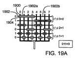
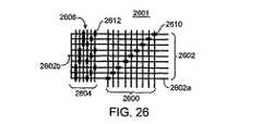
本発明によるミクロ加工された構造体の実施態様は、第二の複数の平行な流れチャンネルに直交する第一の複数の平行な流れチャンネルによって定められる貯蔵場所のアレイを含む。制御ラインのネットワークが貯蔵場所に隣接し、貯蔵場所を孤立させる変形可能なバルブを定める。第一の複数の平行な流れチャンネルの中の流れを制御するために第一のマルチプレクサ構造を構成する。第二の複数の平行な流れチャンネルの中の流れを制御するために第二のマルチプレクサ構造を構成する。 Embodiments of the microfabricated structure according to the present invention include an array of storage locations defined by a first plurality of parallel flow channels orthogonal to the second plurality of parallel flow channels. A network of control lines is adjacent to the storage location and defines a deformable valve that isolates the storage location. A first multiplexer structure is configured to control flow in the first plurality of parallel flow channels. A second multiplexer structure is configured to control the flow in the second plurality of parallel flow channels.
本発明によるミクロ加工された片方向バルブの実施態様は、垂直バイア部分およびシート部分を備える第一のエラストマー層、および可撓性の膜を備える第二のエラストマー層を含む。可撓性の膜は一体化された末端部および一体化されていない末端部を有し、一体化されていない末端部はシート部分と接触し、第二の垂直バイア部分の中に変形するように構成される。 An embodiment of a microfabricated unidirectional valve according to the present invention includes a first elastomer layer comprising a vertical via portion and a seat portion, and a second elastomer layer comprising a flexible membrane. The flexible membrane has an integrated end and a non-integrated end so that the non-integrated end contacts the sheet portion and deforms into the second vertical via portion. Configured.
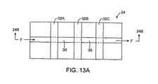
本発明によるミクロ流体装置の別の実施態様は、細長い第一の流れチャンネル、および細長い第一の流れチャンネルに重なり合って第一のバルブ構造体を定める制御チャンネルを含む。バルブ構造体は、細長い第一の流れチャンネルの中に変形して第一の流れチャンネルの第一のセグメントおよび第二のセグメントを定めるように構成される。第二の流れチャンネルが第一のセグメントと流体連通し、第三の流れチャンネルが第二のセグメントと流体連通する。 Another embodiment of a microfluidic device according to the present invention includes an elongated first flow channel and a control channel overlapping the elongated first flow channel and defining a first valve structure. The valve structure is configured to deform into an elongated first flow channel to define a first segment and a second segment of the first flow channel. A second flow channel is in fluid communication with the first segment and a third flow channel is in fluid communication with the second segment.
本発明による不均一な試料の要素を単離する方法の実施態様は、第一の細長いミクロ流体流れチャンネルに沿って不均一な要素を含む試料を流すことを含む。第一の細長い流れチャンネルの上に配置された第一のバルブを作動させて第一および第二のセグメントを定め、これによって第一のセグメントは不均一な試料の第一の要素を含み、第二セグメントは不均一な試料の第二の要素を含む。 An embodiment of a method for isolating a heterogeneous sample element according to the present invention comprises flowing a sample containing the heterogeneous element along a first elongated microfluidic flow channel. A first valve disposed on the first elongate flow channel is actuated to define first and second segments, whereby the first segment includes a first element of non-uniform sample, The two segments contain a second element of the non-uniform sample.
本発明によるミクロ流体装置の別の実施態様は、エラストマー物質の中に定められた選択的にアドレス可能な貯蔵場所を含む。第一の流れチャンネルはバルブを通して貯蔵場所と選択的に流体連通する。第二の流れチャンネルは第二のバルブを通して貯蔵場所と選択的に流体連通する。 Another embodiment of the microfluidic device according to the present invention includes a selectively addressable storage area defined in the elastomeric material. The first flow channel is in selective fluid communication with the storage location through a valve. The second flow channel is in selective fluid communication with the storage location through a second valve.
本発明によるミクロ流体装置の中に物質を選択的に貯蔵および回収する方法の実施態様は、エラストマー物質の中に定められたチャンバを提供することを含む。第一の流れチャンネルの中の第一のバルブを通して物質をチャンバの中に選択的に流し、第二の流れチャンネルの中の第二のバルブを通して物質をチャンバから選択的に流す。 An embodiment of a method for selectively storing and retrieving a material in a microfluidic device according to the present invention includes providing a chamber defined in the elastomeric material. Material is selectively flowed into the chamber through a first valve in the first flow channel and material is selectively flowed out of the chamber through a second valve in the second flow channel.
以上の実施態様およびその他の本発明の実施態様ならびに本発明の利点および特徴を下記の文章および添付の図面によってさらに詳細に説明する。 These and other embodiments of the present invention, as well as the advantages and features of the present invention, will be described in further detail in the following text and accompanying drawings.
(発明の詳細な説明)
(I.ミクロ加工概要)
以下の議論は仮出願ではない2002年4月5日出願の米国特許第10/118,466号、2001年11月28日出願の第09/997,205号、2001年4月6日出願の第09/826,585号、2000年11月28日出願の第09/724,784号および2000年6月27日出願の第09/605,520号明細書に全体として記載されているエラストマー物質を利用するミクロ加工流体装置の作製に関する。これらの特許出願はあらゆる目的の参照によって本明細書中に組み込まれる。(Detailed description of the invention)
(I. Outline of micro processing)
The following discussion is a non-provisional application of US patent application Ser. No. 10 / 118,466 filed on Apr. 5, 2002, No. 09 / 997,205 filed Nov. 28, 2001, filed Apr. 6, 2001. No. 09 / 826,585, 09 / 724,784, filed Nov. 28, 2000, and 09 / 605,520, filed Jun. 27, 2000, the elastomeric material as a whole. The present invention relates to the fabrication of a microfabricated fluid device that utilizes the above. These patent applications are incorporated herein by reference for all purposes.
(1.作製の方法)
本発明を作製する方法の例を本明細書中に提供する。本発明はこれらの方法のいずれか一つによる作製法に限定されないものとする。むしろ、本方法を変更することを含め、本ミクロ構造体を作製するその他の適当な方法もまた本発明の範囲内にある。(1. Manufacturing method)
Examples of methods of making the present invention are provided herein. The present invention is not limited to the manufacturing method by any one of these methods. Rather, other suitable methods of making the microstructure are also within the scope of the invention, including modifying the method.
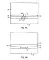
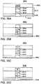
図1から7Bは本ミクロ構造体を作製する第一の好ましい方法(ポンプまたはバルブとして使用することができる)の連続する工程の例を示す。図8から18は本ミクロ構造体を作製する第二の好ましい方法(同じくポンプまたはバルブとして使用することができる)の連続する工程の例を示す。 Figures 1 to 7B show examples of successive steps of the first preferred method of making the microstructures (which can be used as pumps or valves). Figures 8 to 18 show examples of successive steps of a second preferred method of making the present microstructure (which can also be used as a pump or valve).
説明してゆくように、図1から7Bの好ましい方法は、事前に硬化したエラストマー層を用いて組立て、ボンディングすることを含む。別の方法では、エラストマーの各層を「あるべき場所」で硬化してもよい。以下の説明では、「チャンネル」とは流体または気体の流れを束縛することができるエラストマー構造体中の凹部を意味する。 As will be described, the preferred method of FIGS. 1-7B includes assembling and bonding with a pre-cured elastomeric layer. Alternatively, each layer of elastomer may be cured “in place”. In the following description, “channel” means a recess in an elastomeric structure that can constrain fluid or gas flow.
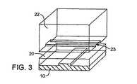
図1を参照して、第一のミクロ機械加工された型10が提供される。ミクロ機械加工された型10は、フォトリソグラフィー、イオンミリングおよび電子線リソグラフィーを含むがこれらに限定されない多数の通常のシリコン加工方法によって作製することができる。 With reference to FIG. 1, a first
図で分かるように、ミクロ機械加工された型10はそれに沿って伸びる張り出したラインまたは凸部11を有する。図に示すように、型10の上に第一のエラストマー層20をキャストし、これによってエラストマー層20の底面に第一の凹部21(凹部22は寸法的に凸部11に対応する)を作製する。 As can be seen, the
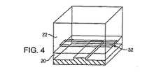
図2で分かるように、それに沿って伸びる張り出した凸部13を有する第二のミクロ機械加工された型12もまた提供される。図に示すように、型12の上に第二のエラストマー層22をキャストし、これによってその底面に凸部13の寸法に対応する凹部23を作製する。 As can be seen in FIG. 2, a second
図3および4に例を示す連続する工程で分かるように、次に第二のエラストマー層22を型12から取り外し、第一のエラストマー層20の上に置く。図で分かるように、第二のエラストマー層22の底面に沿って伸びる凹部23は流れチャンネル32を形成する。 3 and 4, the
図5を参照して、別個のものであった第一および第二のエラストマー層20および22(図4)を次にボンディングして一体化し、一体化された(すなわちモノリス)エラストマー構造体24を作製する。 Referring to FIG. 5, the separate first and second elastomer layers 20 and 22 (FIG. 4) are then bonded together to form an integrated (ie, monolithic) elastomeric structure 24. Make it.
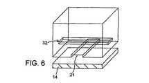
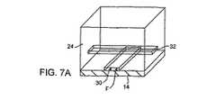
図6および7Aの連続する工程で分かるように、次にエラストマー構造体24を型10から取り外し、平面基板14の上に配置する。図7Aおよび7Bで分かるように、エラストマー構造体24をその底面で平面基板14に密着させると、凹部21は流れチャンネル30を形成することになる。 The
本エラストマー構造体はほぼ任意の滑らかな平面基板と可逆的な密着状態を形成する。このように密着状態を形成することの利点は、エラストマー構造体を剥がして洗浄し、再使用できることである。好ましい様相では平面基板14はガラスである。ガラスを用いるまた別の利点は、ガラスが透明でありエラストマーチャンネルおよび貯蔵室の光学的な検査が可能なことである。あるいは、上記で説明したと同じ方法によって平らなエラストマー層の上にエラストマー構造体をボンディングし、永久的で高強度の結合を形成してもよい。高い背圧を用いるときには、この方法は有利である。 The elastomeric structure forms a reversible adhesion with almost any smooth planar substrate. The advantage of forming a close contact in this way is that the elastomeric structure can be peeled off, washed and reused. In a preferred aspect, the
図7Aおよび7Bで分かるように、好ましくは流れチャンネル30および32は互いにある角度で配置され、基質24の小さな膜25が流れチャンネル30の上部を流れチャンネル32の底部から隔てる。 As can be seen in FIGS. 7A and 7B,
好ましい様相では、平面基板14はガラスである。ガラスを用いる利点は、本エラストマー構造体を剥がして洗浄し、再使用できることである。ガラスを使用するまた別の利点は光感作を使用できることである。あるいは、平面基板14はエラストマー自体であってもよく、高い背圧を用いるときには有利であると分かる。 In a preferred aspect, the
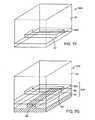
今説明した作製方法を変化させて、装置のチャンネルの壁を形成するエラストマーと異なるエラストマー物質で構成された膜を有する構造を作製してもよい。この変化形の作製方法の例を図7Cから7Gに示す。 The fabrication method just described may be varied to produce a structure having a membrane composed of an elastomeric material different from the elastomer that forms the walls of the device channel. An example of a manufacturing method of this variation is shown in FIGS. 7C to 7G.
図7Cを参照して、第一のミクロ機械加工された型10が提供される。ミクロ機械加工された型10はそれに沿って伸びる張り出したラインまたは凸部11を有する。図7Dでは、第一のエラストマー層20の上部が張り出したラインまたは凸部11の上部と同じ高さになるように、第一のミクロ機械加工された型10の上に第一のエラストマー層20をキャストする。これは、張り出したライン11の既知の高さに対して型10の上にスピンコーティングするエラストマー物質の体積を注意深く制御することによって実現できる。あるいは、射出成形によって所望の形状を作製することができよう。 With reference to FIG. 7C, a first
図7Eでは、それに沿って伸びる張り出した凸部13を有する第二のミクロ機械加工された型12も提供される。図に示すように、型12の上に第二のエラストマー層22をキャストし、これによってその底面に凸部13の寸法に対応する凹部23を作製する。 In FIG. 7E, a second
図7Fでは、第二のエラストマー層22を型12から取り外し、第三のエラストマー層222の上に置く。下記に詳細に説明する技法を用いて、第二のエラストマー層22を第三のエラストマー層20にボンディングし、一体化されたエラストマーブロック224を作製する。プロセス中のこの時点で、以前には張り出したライン13によって占められていた凹部23は流れチャンネル23を形成する。 In FIG. 7F, the
図7Gでは、第一のミクロ機械加工された型10および第一のエラストマー層20の上にエラストマーブロック224を置く。次に、エラストマーブロックと第一のエラストマー層20とをボンディングして一体化し、別個のエラストマー層222で構成された膜を有する一体化された(すなわちモノリス)エラストマー構造体24を作製する。 In FIG. 7G, an
図7Aに関連して上記で説明した方法でエラストマー構造体24をその底面で平面基板に密着させると、以前に張り出したライン11によって占められていた凹部は流れチャンネル30を形成する。 When the
図7C〜7Gに関連して上記で例を示した変化形の作製法は、構造の残りのエラストマー物質とは別の物質で膜部分を構成することが可能になる利点を提供する。装置の動作では膜の厚さおよび弾性は重要な役割を果たすのでこれは重要である。さらに、この方法はエラストマー構造体に組み込む前に別個のエラストマー層の条件を容易に条件付けすることを可能にする。下記で詳しく考察するように、潜在的に望ましい条件の例は、膜の作動を可能にする磁性化学種または電気伝導性化学種の導入および/または膜の弾性を変化させる膜中へのドーパントの導入を含む。 The variant fabrication method illustrated above in connection with FIGS. 7C-7G provides the advantage that it is possible to construct the membrane portion with a material other than the remaining elastomeric material of the structure. This is important because the thickness and elasticity of the membrane play an important role in the operation of the device. In addition, this method allows for easy conditioning of the conditions of a separate elastomer layer prior to incorporation into the elastomer structure. As discussed in detail below, examples of potentially desirable conditions include the introduction of magnetic or electrically conductive species that enable the operation of the film and / or the incorporation of dopants into the film that change the elasticity of the film. Includes introduction.
ミクロ機械加工された型の上で複製成形法によって作製されるさまざまな形状のエラストマー層の作製に関連して上記の方法を示したが、本発明はこの技法に限定されない。他の技法を使用して、ボンディングして一体化する形状を有するエラストマー物質の個々の層を作製してもよい。例えば、第二の方法の例に関連して以下で考察するように、レーザカット法または射出成形、あるいは化学エッチングおよび/または犠牲材料を利用する方法によって形状を有するエラストマー物質の層を作製してもよい。 Although the above method has been illustrated in connection with the production of various shaped elastomeric layers made by a replica molding method on a micromachined mold, the present invention is not limited to this technique. Other techniques may be used to create individual layers of elastomeric material having a shape that bonds together. For example, as discussed below in connection with the second method example, a layer of elastomeric material having a shape may be produced by laser cutting or injection molding, or a method that utilizes chemical etching and / or sacrificial materials. Also good.
別の方法では、エラストマー物質の中にカプセル封じされたフォトレジストの現像を利用してパターン化されたエラストマー構造体を作製する。しかし、本発明による方法はフォトレジストを利用することに限定されない。周囲のエラストマー物質に対して選択的に除去される犠牲物質として金属などその他の物質も使用してよく、このような方法は本発明の範囲内にあろう。例えば、適切な化学薬品混合物を利用してRTV615エラストマーに対して金属の金を選択的にエッチングすることができる。 Another method utilizes patterned development of photoresist encapsulated in an elastomeric material to create a patterned elastomeric structure. However, the method according to the present invention is not limited to utilizing a photoresist. Other materials such as metals may also be used as sacrificial materials that are selectively removed relative to the surrounding elastomeric material, and such methods would be within the scope of the present invention. For example, metal gold can be selectively etched with respect to the RTV615 elastomer using a suitable chemical mixture.
(2.層およびチャンネルの寸法)
ミクロ加工されたとは、本発明の実施態様によって作製されたエラストマー構造体の構造単位のサイズを指す。一般に、ミクロ加工された構造体の少なくとも一つの寸法の変化はミクロンレベルに制御され、少なくとも一つの寸法は微視的(すなわち1000μm未満)である。一般に、ミクロ加工は構造単位の寸法を微視的レベルで製造するために設計されたフォトリソグラフィーおよびスピンコーティングなど半導体またはMEMS作製技法を含み、ミクロ加工された構造体の寸法の少なくともあるものは構造体を適度に解像/画像化するために顕微鏡を必要とする。(2. Layer and channel dimensions)
Microfabricated refers to the size of the structural unit of an elastomeric structure made according to an embodiment of the present invention. In general, the change in at least one dimension of the micromachined structure is controlled to the micron level, and at least one dimension is microscopic (ie, less than 1000 μm). In general, microfabrication involves semiconductor or MEMS fabrication techniques such as photolithography and spin coating designed to produce structural unit dimensions at the microscopic level, with at least some of the dimensions of the micromachined structure being structural. A microscope is required to adequately resolve / image the body.
好ましい様相では、好ましくは流れチャンネル30、32、60および62は約10:1の幅対深さ比を有する。本発明の実施態様による幅対深さ比のその他の範囲を非限定的に列挙すると、0.1:1から100:1、より好ましくは1:1から50;1、より好ましくは2:1から20:1、最も好ましくは3:1から15:1である。例となる様相では、流れチャンネル30、32、60および62は約1から1000ミクロンの幅を有する。本発明の実施態様による流れチャンネルの幅のその他の範囲を非排他的に列挙すると、0.01から1000ミクロン、より好ましくは0.05から1000ミクロン、より好ましくは0.2から500ミクロン、より好ましくは1から250ミクロン、最も好ましくは10から200ミクロンである。チャンネル幅の例は0.1μm、1μm、2μm 、5μm、10μm、20μm、30μm、40μm、50μm、60μm、70μm、80μm、90μm、100μm、110μm、120μm、130μm、140μm、150μm、160μm、170μm、180μm、190μm、200μm、210μm、220μm、230μm、240μmおよび250μmを含む。 In a preferred aspect, preferably the
流れチャンネル30、32、60および62は約1から100ミクロンの深さを有する。本発明の実施態様による流れチャンネルの深さのその他の範囲を非排他的に列挙すると、0.01から1000ミクロン、より好ましくは0.05から500ミクロン、より好ましくは0.2から250ミクロン、より好ましくは1から100ミクロン、より好ましくは2から20ミクロン、最も好ましくは5から10ミクロンである。チャンネル深さの例は0.01μm、0.02μm、0.05μm、0.1μm、0.2μm、0.5μm、1μm、2μm、3μm、4μm、5μm、7.5μm、10μm、12.5μm、15μm、17.5μm、20μm、22.5μm、25μm、30μm、40μm、50μm、75μm、100μm、150μm、200μmおよび250μmを含む。 The
フローチャンネルは上記で示したこれらの特定の寸法範囲および例に限定されず、図27に関連して下記で詳細に考察するように、膜を変形するために必要な力の大きさに影響を及ぼすために幅を変化させてよい。例えば、下記で詳しく考察するように0.01μmのオーダーの幅を有する極めて幅の狭い流れチャンネルは光学およびその他の用途で有用なことがある。上記で説明したよりさらに大きな幅のチャンネルを有する部分を含むエラストマー構造体もまた本発明の範囲にあり、そのような幅の広い流れチャンネルを利用する用途の例には流体貯槽および混合チャンネル構造体が含まれる。 The flow channel is not limited to these specific dimensional ranges and examples given above, and will affect the amount of force required to deform the membrane, as discussed in detail below in connection with FIG. The width may be varied to effect. For example, as discussed in detail below, a very narrow flow channel having a width on the order of 0.01 μm may be useful in optics and other applications. Elastomeric structures that include portions having channels with a larger width than those described above are also within the scope of the present invention, and examples of applications utilizing such wide flow channels include fluid reservoirs and mixing channel structures. Is included.
機械的安定性のためにエラストマー層を厚くキャストしてもよい。実施態様の例では、図1のエラストマー層22は厚さ50ミクロンから数センチメートル、より好ましくは厚さ約4mmである。本発明のその他の実施態様によるエラストマー層の厚さの範囲を非排他的に列挙すると、約0.1ミクロンから10cm、1ミクロンから5cm、10ミクロンから2cm、100ミクロンから10mmの間である。 The elastomer layer may be cast thick for mechanical stability. In an example embodiment, the
従って、流れチャンネル30と32とを隔てる図7Bの膜25は約0.01と1000ミクロンとの間、より好ましくは0.05から500ミクロン、より好ましくは0.2から250、より好ましくは1から100ミクロン、より好ましくは2から50ミクロン、最も好ましくは5から40ミクロンの一般的厚さを有する。従って、エラストマー層22の厚さはエラストマー層20の厚さの約100倍である。例となる膜の厚さは0.01μm、0.02μm、0.03μm、0.05μm、0.1μm、0.2μm、0.3μm、0.5μm、1μm、2μm、3μm、5μm、7.5μm、10μm、12.5μm、15μm、17.5μm、20μm、22.5μm、25μm、30μm、40μm、50μm、75μm、100μm、150μm、200μm、250μm、300μm、400μm、500μm、750μmおよび1000μmを含む。 Thus, the
(3.ソフトリソグラフィーボンディング)
好ましくは、パターン化されたエラストマー層を構成するポリマーに固有の化学的性質を用いてエラストマー層を化学的にボンディングして一体化する。より好ましくは、ボンディングは二つの構成成分の「付加硬化」ボンディングを含む。(3. Soft lithography bonding)
Preferably, the elastomeric layer is chemically bonded and integrated using the chemical properties inherent in the polymer comprising the patterned elastomeric layer. More preferably, the bonding includes two component “addition cure” bonding.
好ましい様相では、層が異なる化学的性質を有する不均一ボンディングでエラストマーのさまざまな層をボンディングして一体化する。あるいは、すべての層が同じ化学的性質である均一ボンディングを使用することがある。第三に、オプションとして各エラストマー層を代わりに接着剤で接着してもよい。第四の様相では、エラストマー層は加熱によってボンディングされる熱硬化性エラストマーであってもよい。 In a preferred aspect, the various layers of elastomer are bonded together by non-uniform bonding where the layers have different chemistries. Alternatively, uniform bonding may be used where all layers have the same chemistry. Third, as an option, each elastomer layer may instead be glued with an adhesive. In a fourth aspect, the elastomer layer may be a thermosetting elastomer that is bonded by heating.
均一ボンディングの一つの様相では、エラストマー層は同じエラストマー物質で構成され、一方の層の同じ化学的実体がもう一方の層の同じ化学的実体と反応して層をボンディングして一体化する。一つの実施態様では、光、熱、または別の化学種との化学反応による架橋剤の活性化から同種のエラストマー層のポリマー鎖の間のボンディングが生じてもよい。 In one aspect of uniform bonding, the elastomeric layers are composed of the same elastomeric material, and the same chemical entity in one layer reacts with the same chemical entity in the other layer to bond the layers together. In one embodiment, bonding between the polymer chains of the same elastomeric layer may result from activation of the crosslinker by light, heat, or a chemical reaction with another chemical species.
あるいは、不均一の様相では、エラストマー層は異なるエラストマー物質で構成され、一方の層の第一の化学的実体が別の層の第二の化学的実体と反応する。一つの不均一の様相の例では、それぞれのエラストマー層をボンディングして一体化するために用いられるボンディングプロセスは、RTV615シリコーンの二つの層をボンディングして一体化することを含んでもよい。RTV615シリコーンは、二部付加硬化シリコーンゴムである。A部はビニル基および触媒を含み、B部は水素化ケイ素(Si‐H)基を含む。RTV615の通常の比は10A:1Bである。ボンディング用に一方の層を30A:1B(すなわちビニル基過剰)で、他層を3A:1B(すなわちSi‐H基過剰)で作製してもよい。各層を別々に硬化する。二つの層を接触させて高温に加熱すると、二つの層は不可逆的にボンディングしてモノリスエラストマー基質を形成する。 Alternatively, in a heterogeneous aspect, the elastomeric layer is composed of a different elastomeric material, and a first chemical entity in one layer reacts with a second chemical entity in another layer. In one example of a non-uniform aspect, the bonding process used to bond and integrate the respective elastomer layers may include bonding and integrating the two layers of RTV615 silicone. RTV 615 silicone is a two-part addition cured silicone rubber. Part A contains vinyl groups and catalyst, and part B contains silicon hydride (Si-H) groups. The normal ratio for RTV 615 is 10A: 1B. For bonding, one layer may be made of 30A: 1B (ie, excess vinyl group) and the other layer may be made of 3A: 1B (ie, Si—H group excess). Each layer is cured separately. When the two layers are brought into contact and heated to a high temperature, the two layers are irreversibly bonded to form a monolith elastomeric substrate.
本発明の様相の例では、シルガード(Sylgard)182、184または186、あるいは脂肪族ウレタンジアクリレート例えば(しかし限定はされない)ユー・シー・ビー・ケミカル(UCB Chemical)からのイベクリル(Ebecryl)270またはイール(Irr)245を利用してエラストマー構造体を作製する。 Examples of aspects of the invention include Sylgard 182, 184 or 186, or aliphatic urethane diacrylate such as (but not limited to) Ebecryl 270 from UCB Chemical, or An elastomer structure is produced using Irr 245.
本発明による一つの実施態様では、純粋なアクリル化ウレタンであるイーベ(Ebe)270から二層エラストマー構造体を作製した。薄い底層を170℃、15秒間、8000rpmでスピンコートした。エレクトロライト社(Electrolite corporation)によって製造されたELC500型装置を利用して、まず上層および底層を窒素雰囲気下で10分間紫外線硬化した。次に組み立てた層をさらに30分間硬化した。反応の触媒としてチバ‐ガイギー・ケミカルズ(Ciba‐Geigy Chemicals)によって製造されたイルガキュア(Irgacure)500の0.5%体積/体積混合物を使用した。生成したエラストマー物質は中程度の弾性およびガラスへの接着強さを示した。 In one embodiment according to the present invention, a bilayer elastomeric structure was made from Ebe 270, a pure acrylated urethane. The thin bottom layer was spin coated at 8000 rpm at 170 ° C. for 15 seconds. Using an ELC500 type apparatus manufactured by Electrolite Corporation, the top and bottom layers were first UV cured for 10 minutes under a nitrogen atmosphere. The assembled layer was then cured for an additional 30 minutes. A 0.5% volume / volume mixture of
本発明による別の実施態様では、薄い底層には25%イーベ270/50%イール245/25%イソプロピルアルコール、および上層としては純粋なアクリレート化ウレタンであるイーベ270を用いる組合せから二層エラストマー構造体を作製した。エレクトロライト社によって製造されたELC500型装置を利用して、窒素雰囲気下紫外線で薄い底層を5分間初期硬化し、上層を10分間初期硬化した。次に、組み立てた層をさらに30分間硬化した。反応用の触媒としてチバ‐ガイギー・ケミカルズによって製造されたイルガキュア500の0.5%体積/体積混合物を使用した。その結果得られたエラストマー物質は中程度の弾性を示し、ガラスに接着した。 In another embodiment according to the present invention, a two-layer elastomeric structure from a combination using 25% ebe 270/50% eel 245/25% isopropyl alcohol as the thin bottom layer and ebe 270 as the pure acrylated urethane as the top layer. Was made. Using an ELC500 type device manufactured by Electrolite, a thin bottom layer was initially cured with ultraviolet light in a nitrogen atmosphere for 5 minutes, and a top layer was initially cured for 10 minutes. The assembled layer was then cured for an additional 30 minutes. A 0.5% volume / volume mixture of
あるいは、例えば、エラストマー層/基質が接触して配置されたときボンディングするようにプラズマ照射によってエラストマー表面を活性化することを含む他のボンディング方法を使用することがある。例えば、同じ物質で構成されているエラストマー層をボンディングさせて一体化させることへの一つの考えられる手法が、参照によって本明細書中に組み込まれるダフィー(Duffy)ら著「ポリ(ジメチルシロキサン)中におけるミクロ流体システムの迅速なプロトタイプ作製法(Rapid Prototyping of Microfluidic Systems in Poly(dimethylsiloxane)」、アナリティカル・ケミストリー(Analytical Chemistry)(1998年)、第70巻、4974〜4984頁によって示されている。この論文は、ポリジメチルシロキサン(PDMS)層を酸素プラズマに暴露すると表面の酸化が引き起こされ、二つの酸化された層を接触して配置すると不可逆なボンディングが起こることを論じている。 Alternatively, other bonding methods may be used including, for example, activating the elastomeric surface by plasma exposure to bond when the elastomeric layer / substrate is placed in contact. For example, one possible approach to bonding and integrating elastomer layers composed of the same material is described in Duffy et al., “Poly (dimethylsiloxane)”, incorporated herein by reference. Rapid Prototyping of Microfluidic Systems in Poly (dimethylsiloxane), Analytical Chemistry (1998), pages 70, 4974, 49-49. This paper shows that exposure of a polydimethylsiloxane (PDMS) layer to oxygen plasma causes surface oxidation and places the two oxidized layers in contact. It argues that the irreversible bonding occurs.
エラストマーの連続する層をボンディングして一体化させるさらに別の手法は、未硬化エラストマーの接着性を利用することである。詳しくは、第一の硬化エラストマー層の上にRTV615などの未硬化エラストマーの薄い層を塗布する。次に、未硬化エラストマー層の上に第二の硬化エラストマー層を配置する。次に、薄い未硬化エラストマー中間層を硬化してモノリスエラストマー構造体を製作する。あるいは、第一の硬化エラストマー層の底に未硬化エラストマーを塗布して、第二の硬化エラストマー層の上に第一の硬化エラストマー層を置いてもよい。中間の薄いエラストマー層を硬化させると、同様にモノリスエラストマー構造体が作製される。 Yet another approach to bonding and integrating successive layers of elastomers is to take advantage of the adhesion of the uncured elastomer. Specifically, a thin layer of uncured elastomer such as RTV 615 is applied over the first cured elastomer layer. Next, a second cured elastomer layer is disposed on the uncured elastomer layer. The thin uncured elastomer intermediate layer is then cured to produce a monolith elastomer structure. Alternatively, an uncured elastomer may be applied to the bottom of the first cured elastomer layer and the first cured elastomer layer may be placed on the second cured elastomer layer. When the intermediate thin elastomer layer is cured, a monolith elastomeric structure is produced as well.
エラストマー構造体を作製するために犠牲層のカプセル封じを使用する場合、既に硬化したエラストマー層およびその上にパターン化された任意の犠牲材料の上に未硬化エラストマーを注ぐことによって連続するエラストマー層のボンディングを実現してもよい。未硬化エラストマー層のポリマー鎖と硬化エラストマー層のポリマー鎖との相互浸透および反応に起因してエラストマー層間のボンディングが起こる。続いてエラストマーを硬化させるとエラストマー層間の結合が創り出され、モノリスエラストマー構造体が創り出される。 When using sacrificial layer encapsulation to make an elastomeric structure, a continuous elastomeric layer is poured by pouring uncured elastomer over the already cured elastomeric layer and any sacrificial material patterned thereon. Bonding may be realized. Bonding between the elastomer layers occurs due to interpenetration and reaction between the polymer chains of the uncured elastomer layer and the polymer chains of the cured elastomer layer. Subsequent curing of the elastomer creates a bond between the elastomer layers and creates a monolith elastomeric structure.
図1から7Bの第一の方法を参照して、ミクロ加工された型12の上にRTV混合物を2000rpmで30秒間スピンコーティングし、約40ミクロンの厚さを作ることによって第一のエラストマー層20を創り出してよい。ミクロ加工された型11の上にRTV混合物をスピンコーティングすることによって、第二のエラストマー層22を創り出してもよい。層20および22の両方を80℃で1.5時間別々に熱処理または硬化してもよい。第一のエラストマー層20の上に第二のエラストマー層22を約80℃で約1.5時間ボンディングしてもよい。 Referring to the first method of FIGS. 1-7B, the
ミクロ機械加工された型10および12はシリコンウエハー上にパターン化されたフォトレジストであってもよい。例となる様相では、シプレー(Shipley)SJR5740フォトレジストを2000rpmでスピンコートし、高分解能透明フィルムをマスクとしてパターン化し、次に現像して高さ約10ミクロンの逆チャンネルを作製した。約200℃で約30分間熱処理すると、フォトレジストはリフローして逆チャンネルは丸みを帯びる。好ましい様相では、シリコーンゴムの接着を防ぐために、型をそれぞれ使用する前に約1分間トリメチルクロロシラン(TMCS)気体で処理してもよい。
(4.適当なエラストマー物質)
オールコック(Allcock)らの「現代ポリマー化学(Contemporory Polymer Chemistry)」、第二版は、一般にエラストマーをガラス転移点と液化温度との間の温度に存在するポリマーとして説明している。ポリマー鎖は力に応答して容易にねじれ運動を行い主鎖のコイル構造がほどけ、力がなくなれば主鎖を巻き戻して以前の形状をとることができるので、エラストマー物質は弾性を示す。一般に、エラストマーは力が加わると変形するが、力が取り除かれるともとの形状に戻る。エラストマー物質によって示される弾性をヤング率によって特性化することができる。本発明によれば、約1Pa〜1TPaの間、より好ましくは約10Pa〜100GPaの間、より好ましくは約20Pa〜1GPaの間、より好ましくは約50Pa〜10MPaの間、より好ましくは約100Pa〜1MPaの間のヤング率を有するエラストマー物質が有用であるが、特定の用途の求めによってこれらの範囲外のヤング率を有するエラストマー物質を利用してもよい。(4. Suitable elastomer material)
Allcock et al., “Contemporary Polymer Chemistry”, second edition, describes elastomers as polymers that generally exist at temperatures between the glass transition temperature and the liquefaction temperature. The elastomeric material exhibits elasticity because the polymer chain easily twists in response to force and unwinds the main chain coil structure, and when the force is lost, the main chain can be rewound to assume the previous shape. Generally, an elastomer deforms when a force is applied, but returns to its original shape when the force is removed. The elasticity exhibited by the elastomeric material can be characterized by Young's modulus. According to the present invention, between about 1 Pa and 1 TPa, more preferably between about 10 Pa and 100 GPa, more preferably between about 20 Pa and 1 GPa, more preferably between about 50 Pa and 10 MPa, more preferably between about 100 Pa and 1 MPa. Elastomeric materials having a Young's modulus of between are useful, but elastomeric materials having a Young's modulus outside these ranges may be utilized depending on the particular application requirements.
非常に多様なエラストマーから本発明のシステムを作製してよい。例となる様相では、好ましくはシリコーンゴムからエラストマー層を調製してよい。しかし、その他の適当なエラストマーを使用してもよい。 The system of the present invention may be made from a wide variety of elastomers. In an exemplary aspect, an elastomer layer may be prepared, preferably from silicone rubber. However, other suitable elastomers may be used.
本発明の例となる様相では、ビニルシラン架橋(種類)シリコーンエラストマー(ファミリー)であるGE RTV615(調合物)などエラストマーポリマーから本システムを作製する。しかし、本システムはポリマーのこの一つの調合物、種類またはこの重合体のファミリーにさえ限定されず、むしろほとんどすべての弾性重合体が適する。本ミクロバルブの好ましい作製方法にとって重要な要件は、複数のエラストマーの層をボンディングして一体化する能力である。多層ソフトリソグラフィーの場合、エラストマーの層を別々に硬化してからボンディングして一体化する。この方式では、硬化した層はボンディングして一体化するために十分な反応性を有することが必要である。層同士が同じ種類で自身にボンディングすることができるか、あるいは層同士は二つの異なる種類で互いにボンディングすることができるかのどちらかであればよい。他の可能性として、層の間の接着剤の使用および熱硬化性エラストマーの使用が含まれる。 In an exemplary aspect of the present invention, the system is made from an elastomeric polymer such as GE RTV615 (formulation), which is a vinylsilane cross-linked (type) silicone elastomer (family). However, the system is not limited to this one formulation of polymer, type or even this family of polymers, but rather almost all elastomeric polymers are suitable. An important requirement for the preferred fabrication method of the microvalve is the ability to bond and integrate multiple layers of elastomer. In the case of multilayer soft lithography, the elastomer layers are cured separately and then bonded together. In this scheme, the cured layer must be sufficiently reactive to bond and integrate. It is only necessary that the layers can be bonded to themselves of the same type, or the layers can be bonded to each other in two different types. Other possibilities include the use of adhesives between layers and the use of thermoset elastomers.
重合体の化学的性質、前駆体、合成方法、反応条件、および潜在的な添加剤の非常な多様さを考慮すると、モノリスエラストマーミクロバルブおよびポンプを作るために使用できる膨大な数の可能なエラストマーシステムがある。用いられる物質の変化は、特定の物性、すなわち耐溶剤性、剛性、気体透過性、または温度安定性の求めによって最も強く推進されよう。 Given the great variety of polymer chemistry, precursors, synthesis methods, reaction conditions, and potential additives, the vast number of possible elastomers that can be used to make monolithic elastomer microvalves and pumps There is a system. Changes in the materials used will be most strongly driven by the demands of specific physical properties, ie solvent resistance, stiffness, gas permeability, or temperature stability.
実に多くの種類のエラストマー重合体がある。比較的「標準的な」ポリマーを用いてもなおボンディングには多数の可能性が存在することを示すことを意図して、本明細書中にはエラストマーの最も一般的なクラスの簡単な説明を示す。通常のエラストマー重合体はポリイソプレン、ポリブタジエン、ポリクロロプレン、ポリイソブチレン、ポリ(スチレン‐ブタジエン‐スチレン)、ポリウレタンおよびシリコーンを含む。 There are indeed many types of elastomeric polymers. A brief description of the most common class of elastomers is provided herein, with the intention of showing that there are still many possibilities for bonding using relatively “standard” polymers. Show. Typical elastomeric polymers include polyisoprene, polybutadiene, polychloroprene, polyisobutylene, poly (styrene-butadiene-styrene), polyurethane and silicone.
(ポリイソプレン、ポリブタジエン、ポリクロロプレン)
ポリイソプレン、ポリブタジエンおよびポリクロロプレンはすべてジエンモノマーから重合され、従って重合されるとモノマーあたり一個の二重結合を有する。この二重結合によって加硫(基本的には硫黄を用いて加熱によって二重結合間に架橋を作製する)によって重合体をエラストマーに変換することができる。これを用いると、ボンディングされる層の不十分な加硫によって均一多層ソフトリソグラフィーが容易に可能になり、類似の機構によってフォトレジストカプセル封じが可能である。(Polyisoprene, polybutadiene, polychloroprene)
Polyisoprene, polybutadiene and polychloroprene are all polymerized from diene monomers and thus have one double bond per monomer when polymerized. This double bond allows the polymer to be converted to an elastomer by vulcanization (basically using sulfur to create crosslinks between the double bonds by heating). With this, uniform multi-layer soft lithography is readily possible due to insufficient vulcanization of the layers to be bonded, and photoresist encapsulation is possible by a similar mechanism.
(ポリイソブチレン)
純粋なポリイソブチレンには二重結合はないが、エラストマーとして使用するために重合中に少量(〜1%)のイソプレンを含有させることによって架橋させる。イソプレンモノマーはポリイソブチレン主鎖にペンダント二重結合を付与し、上記と同様に加硫することができる。(Polyisobutylene)
Pure polyisobutylene has no double bonds, but is crosslinked by the inclusion of a small amount (˜1%) of isoprene during polymerization for use as an elastomer. The isoprene monomer imparts a pendant double bond to the polyisobutylene main chain and can be vulcanized in the same manner as described above.
(ポリ(スチレン‐ブタジエン‐スチレン))
ポリ(スチレン‐ブタジエン‐スチレン)はリビングアニオン重合(すなわち反応中に自然な連鎖停止段階がない)によって製造され、従って硬化した重合体中には「生きている」重合体末端が存在し得る。これによって当然この共重合体は本フォトレジストカプセル封じシステム(硬化した層の上に注いだ液体層中に多量の未反応モノマーがある)の候補になる。不十分な硬化を用いると均一多層ソフトリソグラフィー(AとAとのボンディング)が可能になろう。この化学的性質によってブタジエン過剰量およびカップリング剤を有する一つの層(「A」)と、ブタジエン不足量を有するもう一方の層(「B」)(不均一多層ソフトリソグラフィー用)を作ることも可能になる。SBSは「熱硬化性エラストマー」である。これはある温度より上ではSBSは融解して可塑性(弾性に対して)になり、温度を低下させると再びエラストマーになることを意味する。従って、加熱によって層をボンディングして一体化することができる。(Poly (styrene-butadiene-styrene))
Poly (styrene-butadiene-styrene) is produced by living anionic polymerization (ie, there is no natural chain termination step in the reaction), so there can be “live” polymer ends in the cured polymer. This naturally makes this copolymer a candidate for the present photoresist encapsulation system (there is a large amount of unreacted monomer in the liquid layer poured over the cured layer). With insufficient curing, uniform multilayer soft lithography (A to A bonding) would be possible. This chemistry can also make one layer (“A”) with butadiene excess and coupling agent and another layer (“B”) with butadiene deficiency (for heterogeneous multilayer soft lithography). It becomes possible. SBS is a “thermoset elastomer”. This means that SBS melts and becomes plastic (relative to elasticity) above a certain temperature, and becomes elastomer again when the temperature is lowered. Therefore, the layers can be bonded and integrated by heating.
(ポリウレタン)
ポリウレタンはジイソシアネート(A‐A)とジアルコールまたはジアミン(B‐B)とから製造される。非常に多様なジイソシアネートおよびジアルコール/ジアミンがあるので、異なる種類のポリウレタンの数は膨大である。しかし、このポリマーのA対Bの性質から、一つの層中に過剰のA‐A、もう一方の層中に過剰のB‐Bを使用することにより、このポリマーはちょうどRTV615と同じように不均一多層ソフトリソグラフィー用に有用になる。(Polyurethane)
Polyurethanes are made from diisocyanates (AA) and dialcohols or diamines (BB). Since there are a great variety of diisocyanates and dialcohols / diamines, the number of different types of polyurethanes is enormous. However, due to the A-to-B nature of this polymer, by using excess AA in one layer and excess BB in the other layer, this polymer is just as devoid of RTV615. Useful for uniform multilayer soft lithography.
(シリコーン)
シリコーン重合体にはおそらく最大の構造多様性があり、ほとんど確実に最大数の市販調合物がある。RTV615のビニル‐(Si‐H)間架橋(不均一多層ソフトリソグラフィーおよびフォトレジストカプセル封じを両方とも可能にする)についてはすでに考察したが、これはシリコーンポリマー化学で使用されるいくつかの架橋方法のほんの一つでしかない。(silicone)
Silicone polymers probably have the greatest structural diversity, almost certainly the largest number of commercial formulations. Although RTV615's vinyl- (Si-H) cross-linking (allowing both non-uniform multi-layer soft lithography and photoresist encapsulation) has already been discussed, this is some cross-linking method used in silicone polymer chemistry. It ’s just one of them.
(5.装置の動作)
図7Bおよび7Hは一緒になって、第二の流れチャンネルに圧力を加えることによる第一の流れチャンネルの閉鎖を示す。図7B(対応する図7Aの流れチャンネル32で切った正面断面図)は開いている第一の流れチャンネル30を示し、図7Hは第二の流れチャンネル32の加圧によって閉められた第一の流れチャンネル30を示す。(5. Operation of the device)
7B and 7H together show the closure of the first flow channel by applying pressure to the second flow channel. FIG. 7B (front sectional view taken along the
図7Bを参照して、第一の流れチャンネル30および第二の流れチャンネル32を示す。膜25は第一の流れチャンネル30の上部および第二の流れチャンネル32の底部を形成して流れチャンネルを隔てている。図から分かるように流れチャンネル30は「開いて」いる。 Referring to FIG. 7B, a
図7Hで分かるように、流れチャンネル32に圧力を加える(中に導入された気体または液体による)ことによって膜25を下向きに変形させ、それによって流れチャンネル30中を通る流れFを締めつけて遮断する。従ってチャンネル32の中の圧力を変化させることによって線形作動可能なバルブ調節システムが提供され、これによって膜25を望むように動かすことにより流れチャンネル30を開閉できる(図7Gのチャンネル30は例を示す目的のためにだけ「完全に閉まった」位置ではなく「ほとんど閉まった」位置で示してある)。 As can be seen in FIG. 7H, pressure is applied to the flow channel 32 (due to gas or liquid introduced therein) to deform the
そのようなバルブはチャンネルの屋根自体を動かすこと(すなわち膜25を動かすこと)によって作動するので、この技法によって製造されたバルブおよびポンプは真にゼロのデッドボリュームを有し、この技法によって作製された切り替えバルブはバルブの能動体積、例えば約100×100×10μm=100pLにほぼ等しいデッドボリュームを有する。移動膜によって無駄に使われるそのようなデッドボリュームおよび面積は、既知の通常のミクロバルブより約2桁小さい。本発明は大小のバルブおよび切り替えバルブを包含し、デッドボリュームの範囲を非排他的に列挙すると、1aL(アトリットル)から1uL、100aLから100nL、1fL(フェムトリットル)から10nL、100fLから1nL、および1pLから100pLを含む。 Since such valves operate by moving the channel roof itself (ie, moving the membrane 25), valves and pumps manufactured by this technique have a truly zero dead volume and are made by this technique. The switching valve has a dead volume approximately equal to the active volume of the valve, for example about 100 × 100 × 10 μm = 100 pL. Such dead volume and area wasted by moving membranes is about two orders of magnitude smaller than known normal microvalves. The present invention includes large and small valves and switching valves, non-exclusively enumerating dead volume ranges: 1 aL (attoliter) to 1 uL, 100 aL to 100 nL, 1 fL (femtoliter) to 10 nL, 100 fL to 1 nL, and Contains 1 pL to 100 pL.
本発明によるポンプおよびバルブによって吐出することができる極めて小さな体積は重要な利点を表す。詳しくは、手動で計量することができる流体の既知の最少体積は約0.1μlである。自動化システムによって計量することができる既知の最少体積は約10倍大きい(1μl)。本発明によるポンプおよびバルブを利用することによって、10nl以下の液体の体積を普通に計量し、小分けすることができる。本発明によって可能になる極小体積の流体の正確な計量は診断試験およびアッセイを含む非常に多数の生物用途で極めて価値の高いものであろう。 The very small volume that can be dispensed by the pump and valve according to the invention represents an important advantage. Specifically, the known minimum volume of fluid that can be manually metered is about 0.1 μl. The known minimum volume that can be metered by an automated system is about 10 times larger (1 μl). By utilizing the pumps and valves according to the present invention, the volume of liquid below 10 nl can be normally metered and subdivided. The precise metering of very small volumes of fluids enabled by the present invention will be extremely valuable in a large number of biological applications, including diagnostic tests and assays.
式1は均一な厚さの長方形、線形、弾性、等方性平板の加えられた力による変形の非常に簡略化された数学モデルを表す。すなわち、
(1) w=(BPb4)/(Eh3)
式中、w=平板の変形、
B=形状係数(長さ対幅および平板の辺の支持体に依存する)、
P=加えられた圧力、
b=平板の幅
E=ヤング率、および
h=プレート厚さ
である。
(1) w = (BPb4 ) / (Eh3 )
Where w = deformation of the flat plate,
B = shape factor (depends on length vs. width and support of the sides of the plate),
P = applied pressure,
b = plate width E = Young's modulus, and h = plate thickness.
従ってこの極めて簡略化された式においてさえ、圧力に応答するエラストマー膜の変形は膜の長さ、幅、および厚さ、膜の柔軟性(ヤング率)および加えられた作動力の関数である。これらのパラメータは本発明による特定のエラストマー装置の実際の寸法および物理的組成に依存してそれぞれ幅広く変化するので、本発明は広い範囲の膜厚および弾性率、チャンネル幅、および作動力を包含する。 Thus, even in this very simplified formula, the deformation of the elastomeric membrane in response to pressure is a function of the membrane length, width and thickness, membrane flexibility (Young's modulus) and applied actuation force. Since these parameters vary widely depending on the actual dimensions and physical composition of a particular elastomeric device according to the present invention, the present invention encompasses a wide range of film thickness and elastic modulus, channel width, and actuation force. .
一般に膜は一様な厚さを有さず、膜厚は長さおよび幅と比較して必ずしも小さくなく、変形は膜の長さ、幅、または厚さと比較して必ずしも小さくないので、先に示したばかりの式は近似式でしかないことを理解すべきである。それでも、この式は加えられた力に対する変形の所望の応答を実現するための可変パラメータの調節の有用なガイドとして役に立つ。 In general, the membrane does not have a uniform thickness, the thickness is not necessarily small compared to the length and width, and the deformation is not necessarily small compared to the length, width, or thickness of the membrane. It should be understood that the equation just shown is only an approximation. Nevertheless, this equation serves as a useful guide for adjusting the variable parameters to achieve the desired response of the deformation to the applied force.
図8Aおよび8Bは、幅100μmの第一の流れチャンネル30および幅50μmの第二の流れチャンネル32について、バルブ開口率対加えられた圧力の例を示す。約30μmの厚さおよび約750kPaのヤング率を有するジェネラル・エレクトリック・シリコーン(General Electric Silicones)のRTV 615の層によってこの装置の膜を作製した。図21aおよび21bは加えられた圧力の大部分の範囲でバルブの開口の度合いが実質的に線形であることを示している。 8A and 8B show examples of valve opening ratio versus applied pressure for a
0.025インチの外径および0.013インチの内径を有する25mmのステンレス鋼の皮下注射管に接続した0.025インチの外径を有する長さ10cmのプラスチック配管用の管を通して空気圧を加え、この装置の膜を作動させた。制御チャンネルに垂直な方向でこの配管をエラストマーブロック中に挿入することによって制御チャンネルと接触する位置に置いた。皮下注射管には、リー社(Lee Co.)によって製造された外部LHDAミニチュア電磁弁から空気圧を加えた。 Apply air pressure through a 10 cm long plastic tubing tube having a 0.025 inch outer diameter connected to a 25 mm stainless steel hypodermic tube having an outer diameter of 0.025 inch and an inner diameter of 0.013 inch; The device membrane was activated. The tubing was placed in contact with the control channel by inserting it into the elastomer block in a direction perpendicular to the control channel. Air pressure was applied to the hypodermic tube from an external LHDA miniature solenoid valve manufactured by Lee Co.
この装置の中の物質の流れの制御について、ここまでは加えた気体の圧力を利用して説明してきたが、その他の流体を使用してもよい。 Although the control of the substance flow in this apparatus has been described so far by using the pressure of the applied gas, other fluids may be used.
例えば、空気は圧縮性であり、従って外部電磁弁によって圧力を加える時点とこの圧力が膜によって感じられる時点との間に有限の遅延が存在する。本発明の別の実施形態においては、外部供給源から水または油圧作動油などの非圧縮性流体に圧力を加え、加えられた圧力がほとんど瞬間的に膜に伝達されるようにしてもよい。しかし、バルブの変位体積が大きいか、または制御チャンネルの幅が狭いとき、制御流体の粘度が高いと作動を遅延させるもとになることがある。従って、圧力を伝達するための最適媒体は特定の用途および装置構成に依存し、本発明は気体媒体および液体媒体の両方を包含する。 For example, air is compressible, so there is a finite delay between when pressure is applied by an external solenoid valve and when this pressure is felt by the membrane. In another embodiment of the invention, pressure may be applied to an incompressible fluid such as water or hydraulic fluid from an external source so that the applied pressure is transmitted to the membrane almost instantaneously. However, when the displacement volume of the valve is large or the width of the control channel is narrow, the viscosity of the control fluid can be a cause of delaying operation. Thus, the optimal medium for transmitting pressure depends on the particular application and equipment configuration, and the present invention encompasses both gaseous and liquid media.
上記で説明した外部から加えられ圧力は圧力調節器および外部ミニチュアバルブを通してポンプ/タンクシステムによって加えられたが、ガスタンク、コンプレッサ、ピストンシステムおよび液体のカラムを含む外部圧力を加えるその他の方法もまた本発明中に包含される。また、例えば血圧、胃圧、髄液中に存在する圧力、眼内空間中に存在する圧力、および通常の屈曲時に筋肉によって及ぼされる圧力など生体系で見出だされることがある天然に発生する圧力源の使用も包含される。ミニチュアバルブ、ポンプ、巨視的蠕動ポンプ、ピンチバルブ、および当分野において知られているその他の種類の流体調節装置など、外部圧力を調節するその他の方法もまた包含される。 Although the externally applied pressure described above was applied by a pump / tank system through a pressure regulator and an external miniature valve, other methods of applying external pressure including gas tanks, compressors, piston systems, and liquid columns are also available. Included in the invention. Also, naturally occurring that may be found in biological systems such as blood pressure, gastric pressure, pressure in cerebrospinal fluid, pressure in the intraocular space, and pressure exerted by muscles during normal flexion Also included is the use of a pressure source. Other methods of regulating external pressure are also included, such as miniature valves, pumps, macroscopic peristaltic pumps, pinch valves, and other types of fluid regulating devices known in the art.
図で分かるように、本発明の実施態様によるバルブの応答はその動作範囲の大部分でほとんど完全に線形であり、最小限のヒステリシスしかないことが実験的に示された。従って、本バルブはミクロ流体計量および流体制御に理想的に適している。バルブ応答の直線性は個々のバルブがフックの法則のばねとして十分にモデル化できることを示している。さらにまた、単に作動圧を高めることによって流れチャンネルの中の高い圧力(すなわち背圧)に対抗できる。実験的に、本発明者らは70kPaの背圧でバルブ閉鎖を実現したが、さらに高い圧力もまた包含される。以下に本発明によって包含される圧力範囲を非排他的に列挙する。すなわち10Pa〜25MPa、100Pa〜10MPa、1kPa〜1MPa、1kPa〜300kPa、5kPa〜200kPa、および15kPa〜100kPa。 As can be seen, it has been experimentally shown that the valve response according to an embodiment of the present invention is almost perfectly linear over most of its operating range, with minimal hysteresis. The valve is therefore ideally suited for microfluidic metering and fluid control. The linearity of the valve response indicates that individual valves can be well modeled as hook-law springs. Furthermore, the high pressure in the flow channel (ie back pressure) can be countered simply by increasing the operating pressure. Experimentally, we realized valve closure with a back pressure of 70 kPa, but higher pressures are also included. The following is a non-exclusive list of pressure ranges encompassed by the present invention. That is, 10 Pa to 25 MPa, 100 Pa to 10 MPa, 1 kPa to 1 MPa, 1 kPa to 300 kPa, 5 kPa to 200 kPa, and 15 kPa to 100 kPa.
バルブおよびポンプを開閉するために線形作動を必要とはしないが、線形応答であればバルブを計量装置としてより簡単に使用することが可能になる。本発明の一つの実施態様では、バルブの開口率を用いて既知の閉度に部分的に作動させることによって流速を制御する。線形のバルブ作動によって、バルブを所望の閉度で閉めるために必要とされる作動力の量を決定することがより簡単になる。線形作動の別の利点は、流れチャンネルの中の圧力からバルブ作動のために必要とされる力を簡単に決定できることである。作動が線形なら、流れチャンネルの中の圧力が増大しても同じ圧力(単位面積あたりの力)をバルブの作動部分に加えることによって対抗できる。 Although linear actuation is not required to open and close the valve and pump, a linear response allows the valve to be used more easily as a metering device. In one embodiment of the present invention, the flow rate is controlled by partially actuating to a known degree of closure using the valve aperture. Linear valve actuation makes it easier to determine the amount of actuation force required to close the valve with the desired degree of closure. Another advantage of linear actuation is that the force required for valve actuation can be easily determined from the pressure in the flow channel. If the actuation is linear, it can be countered by applying the same pressure (force per unit area) to the working part of the valve as the pressure in the flow channel increases.
バルブの直線性はバルブ構造体物の構造、組成および作動方法に依存する。さらにまた、直線性がバルブの望ましい特性であるかどうかは用途に依存する。従って、線形および非線形作動可能なバルブが本発明に包含され、バルブが線形に作動可能である圧力範囲は特定の実施態様によって変化する。 The linearity of the valve depends on the structure, composition and method of operation of the valve structure. Furthermore, whether linearity is a desirable characteristic of a valve depends on the application. Thus, linear and non-linearly actuatable valves are encompassed by the present invention, and the pressure range over which the valve is linearly actuable varies depending on the particular implementation.
図9は上記で説明したようにチップから空気圧バルブに接続された長さ10cmの空気配管を有する100μm×100μm×10μmのRTVマイクロバルブの時間応答(すなわち、時間の関数として加えられた圧力の変化に応答するバルブの閉度)の例を示す。 FIG. 9 shows the time response of a 100 μm × 100 μm × 10 μm RTV microvalve with a 10 cm long air line connected from the tip to the pneumatic valve as described above (ie, the change in pressure applied as a function of time). An example of the valve closing degree responding to the above.
図9には、デジタル制御信号の二区間、配管末端の実際の空気圧およびバルブ開口率を示す。制御ラインに加えられた圧力は100kPaであり、バルブを閉めるために必要とされる〜40kPaより十分に高い。従って、閉めるときにはバルブは必要な圧力よりも60kPa大きな圧力で押されて閉まる。しかし、開くときにはバルブは自身のばね力(≦40kPa)だけによってその休止位置へ引き戻される。従って、τ閉はτ開より小さいと予測される。圧力を制御するために用いられるミニチュアバルブの制約によって、制御信号と制御圧力応答との間にもまた遅れがある。そのような遅れをtと呼び1/e時定数をτと呼ぶと、それらの値は以下のようである。すなわち、t開=3.63ms(ミリ秒)、τ開=1.88ms、t閉=2.15ms、τ閉=0.51ms。開閉動作にそれぞれ3τを当てることが可能なら、バルブは水溶液で満たされたとき75Hzで円滑に動作する。 FIG. 9 shows the two sections of the digital control signal, the actual air pressure at the end of the pipe, and the valve opening ratio. The pressure applied to the control line is 100 kPa, well above the ~ 40 kPa required to close the valve. Therefore, when closing, the valve is pushed and closed with a
開閉遅れの問題がまったくない別の作動方法を使用したら、このバルブは〜375Hzで動作するであろう。また、膜厚を変えることによって、ばね定数を調節してもよいことに注意すること。これによって迅速な開放動作または迅速な閉鎖動作のどちらかの最適化が可能になる。膜の中へのドーパントの導入または膜として機能する(図7C〜7Hに関連して上記で説明した)別のエラストマー物質の利用によって可能であるように、膜の弾性(ヤング率)を変えることによってばね定数を調節することもできよう。 If another method of operation with no open / close delay problems is used, this valve will operate at ~ 375 Hz. Also note that the spring constant may be adjusted by changing the film thickness. This allows optimization of either a quick opening action or a quick closing action. Changing the elasticity (Young's modulus) of the film, as possible by introducing dopants into the film or by using another elastomeric material (described above in connection with FIGS. 7C-7H) that functions as a film. The spring constant could be adjusted by
図9に例を示すようにバルブの性質を実験的に測定するとき、蛍光によってバルブ開口率を測定した。これらの実験では、緩衝液(pH≧8)中のフルオレセインイソチオシアネート(FITC)溶液で流れチャンネルを満たし、10kHzバンド幅を有する光電子増倍管を備えた落射蛍光顕微鏡でチャンネルの中央の〜1/3を占める正方形の区域の蛍光をモニターした。ほとんど同一の空気配管を通して制御ラインと同時に圧力を加えたホイートストンブリッジ圧力センサ(センシム(SenSym)SCC15GD2)で圧力をモニターした。 When the characteristics of the bulb were experimentally measured as shown in FIG. 9, the bulb aperture ratio was measured by fluorescence. In these experiments, the flow channel was filled with a solution of fluorescein isothiocyanate (FITC) in a buffer (pH ≧ 8), and an epifluorescence microscope equipped with a photomultiplier tube having a 10 kHz bandwidth had a ˜1 / The fluorescence of the square area occupying 3 was monitored. Pressure was monitored with a Wheatstone bridge pressure sensor (SenSym SCC15GD2) that applied pressure through almost the same air line at the same time as the control line.
(6.流れチャンネル断面)
オプションとして、所望の用途によって、種々の断面サイズおよび形状を有する本発明の流れチャンネルを設計して種々の利点を提供してよい。例えば、下段の流れチャンネルの断面形状は全長にわたって、または交差する上段の流れチャンネル)の下に配置された部分で、湾曲した上面を有してもよい。そのような湾曲した上面は以下のようにバルブ密閉を容易にする。(6. Flow channel cross section)
Optionally, depending on the desired application, the flow channel of the present invention having various cross-sectional sizes and shapes may be designed to provide various advantages. For example, the cross-sectional shape of the lower flow channel may have a curved upper surface at a portion disposed under the entire length or intersecting the upper flow channel). Such a curved top surface facilitates valve sealing as follows.
図10を参照して、流れチャンネル30および32を通る断面図(図7Bのそれと類似の)を示す。図で分かるように、流れチャンネル30の断面形状は長方形である。図10に示すように、本発明の別の好ましい様相では、流れチャンネル30の断面は長方形に代わって上部湾曲面を有する。 Referring to FIG. 10, a cross-sectional view (similar to that of FIG. 7B) through
まず図10を参照して、流れチャンネル32に圧力が加えられると流れチャンネル30と32とを隔てているエラストマーブロック24の膜部分25は点線で示す連続する位置25A、25B、25C、25Dおよび25Eへ下向きに動く。図で分かるように、平面基板14に隣接する流れチャンネル30の辺で不完全な密閉を生じることがある。 Referring first to FIG. 10, when pressure is applied to the
図10に代わる図11の好ましい実施態様では、流れチャンネル30aは湾曲した上部壁25Aを有する。流れチャンネル32に圧力が加えられると膜部分25は点線で示す連続位置25A2、25A3、25A4および25A5へ下向きに動く。このとき、膜の辺部分がまず流れチャンネルの中に動き、続いて上部膜部分が動く。膜25Aにそのような湾曲した上面を有する利点は、流れチャンネル32に圧力が加えられるとき、より完全な密着が提供されることである。詳しくは、流れチャンネル30の上部壁は平面基板14に対して連続的な接触辺を提供し、それによって図10で壁25と流れチャンネル30の底部との間で見られた「島」接触を回避する。 In the preferred embodiment of FIG. 11 instead of FIG. 10, the flow channel 30a has a curved
膜25Aで湾曲した流れチャンネル上部面を有する別の利点は、膜が作動に応答して流れチャンネルの形状および体積により容易に変形できることである。詳しくは、長方形の流れチャンネルを使用する場合、全周辺(流れチャンネルの高さと流れチャンネルの幅の和の2倍)を流れチャンネルの中に押し込まれなければならない。しかしアーチ型の流れチャンネルを使用する場合、より小さな周辺の物質(半円形アーチ型の部分だけ)を流れチャンネルの中に押し込めばよい。このように、膜が作動するために周辺で必要な変化はより少なく、従って流れチャンネルを遮断するために加えられた作動力に対する応答性がより高い。 Another advantage of having a curved flow channel top surface with
別の様相(図示していない)では、湾曲した面が上記で説明した図20に見られる湾曲した上部壁25Aと対になるように流れチャンネル30の底部に丸みを帯びさせる。 In another aspect (not shown), the bottom of the
要約すると、作動によって膜に起こる実際の配置変化は特定のエラストマー構造体の構成に依存する。詳しくは、配置変化は膜の長さ、幅および厚さプロフィル、構造の残りの部分へのその取り付け方、および流れチャンネルおよび制御チャンネルの高さ、幅および形状ならびに用いられたエラストマーの物性に依存する。加えられた圧力に応答する膜の作動は磁力または静電気力に応答する作動とは若干異なると考えられるので、配置変化は作動の方法にも依存する。 In summary, the actual configuration change that occurs in the membrane upon actuation depends on the configuration of the particular elastomeric structure. Specifically, the placement changes depend on the length, width and thickness profile of the membrane, its attachment to the rest of the structure, and the height, width and shape of the flow and control channels and the physical properties of the elastomer used. To do. Since the operation of the membrane in response to applied pressure is considered to be slightly different from the operation in response to magnetic or electrostatic forces, the change in configuration also depends on the method of operation.
さらに、膜の望ましい配置変化はエラストマー構造体の特定の用途によっても変わる。上記で説明した最も簡単な実施態様では、バルブは開いているか閉まっているかであり、計量してバルブの閉度を制御する。しかし他の実施態様では、膜および/または流れチャンネルの形状を変えてもっと複雑な流れ制御を実現することが望ましいことがある。例えば、膜部分の下で張り出した凸部を有する流れチャンネルを提供し、これによって膜は作動すると流れチャンネル中の流れのある百分率だけを遮断し、遮断された流れの百分率を加えられた作動力には依らないようにできよう。 Furthermore, the desired placement changes of the membrane will also depend on the particular application of the elastomeric structure. In the simplest embodiment described above, the valve is open or closed and is metered to control the degree of valve closure. However, in other embodiments it may be desirable to change the shape of the membrane and / or flow channel to achieve more complex flow control. For example, providing a flow channel with protrusions that protrude below the membrane portion, whereby the membrane will only block a certain percentage of the flow in the flow channel when activated, and an actuating force applied with a percentage of the blocked flow You can avoid depending on.
多くの膜厚プロフィル、および長方形、台形、円形、楕円形、放物線形、双曲線形、および多角形、ならびに上記形状の一部分を含む流れチャンネル断面は本発明によって包含される。考察したばかりの凸部を有する実施態様または流れチャンネルの中に凹部を有する実施態様など、もっと複雑な断面形状も本発明によって包含される。 Many film thickness profiles and flow channel cross sections including rectangular, trapezoidal, circular, elliptical, parabolic, hyperbolic, and polygonal, and portions of the above shapes are encompassed by the present invention. More complex cross-sectional shapes are also encompassed by the present invention, such as those embodiments having convex portions just discussed or embodiments having concave portions in the flow channel.
さらに、上記では主としてエラストマーから流れチャンネルの壁および天井を作製し、下層の基板からチャンネルの床を作製する実施態様によって本発明を説明したが、本発明はこの特定の配向に限定されない。下層の基板中に流れチャンネルの壁および床を作製し、流れチャンネルの天井だけをエラストマーから構築することもできよう。このエラストマー流れチャンネルの天井は加えられた作動力に応答してチャンネルの中に下向きに突出し、それによって流れチャンネル中の物質の流れを制御する。一般に、本出願中の他の箇所に記載されているモノリスエラストマー構造体の方がミクロ流体用途には好ましい。しかし、基板中に作製したチャンネルが利点を提供する場合には、そのような配置を使用することが有用なことがある。例えば、光導波管を含む基板を構築して、光導波管によってミクロ流体チャンネルの側に光を特に誘導することができよう。 Furthermore, although the invention has been described above by embodiments in which flow channel walls and ceilings are made primarily from elastomers and channel floors are made from underlying substrates, the invention is not limited to this particular orientation. It would also be possible to create flow channel walls and floors in the underlying substrate and to build only the flow channel ceiling from elastomer. The ceiling of the elastomeric flow channel protrudes downward into the channel in response to an applied actuation force, thereby controlling the flow of material in the flow channel. In general, monolithic elastomer structures described elsewhere in this application are preferred for microfluidic applications. However, it may be useful to use such an arrangement if the channels made in the substrate provide advantages. For example, a substrate including an optical waveguide could be constructed, and light could be specifically directed to the microfluidic channel side by the optical waveguide.
(7.ネットワーク化システム)
図12Aおよび12Bは上記(例えば図7A)で示したシステムと同一の単一のオン/オフバルブの図を示す。図13Aおよび13Bは図12に示したものと同じであるが一緒にネットワーク化されている単一のアドレス可能なオン/オフバルブの集まりで構成されている蠕動ポンプシステムを示す。図14は、図13の蠕動ポンプシステムについて、実験的に実現したポンプ速度対周波数を示すグラフである。図15Aおよび15Bは、単一の制御ラインによって制御可能な複数の流れチャンネルの概略図を示す。このシステムも図12の単一のアドレス可能なオン/オフバルブの集まりで構成され、マルチプレクス化されているが、図12のものとは配置が異なる。図16は、選ばれたチャンネル中の流体の流れを可能にするのに適する多重化システムの概略の例であり、図12の単一のオン/オフ動作バルブの集まりで構成され、接続または一緒にネットワーク化されている。(7. Networked system)
12A and 12B show a diagram of a single on / off valve identical to the system shown above (eg, FIG. 7A). FIGS. 13A and 13B show a peristaltic pump system that consists of a collection of single addressable on / off valves similar to that shown in FIG. 12, but networked together. FIG. 14 is a graph showing pump speed versus frequency experimentally realized for the peristaltic pump system of FIG. 15A and 15B show a schematic diagram of multiple flow channels that can be controlled by a single control line. This system is also composed of a collection of single addressable on / off valves of FIG. 12 and is multiplexed, but the arrangement is different from that of FIG. FIG. 16 is a schematic example of a multiplexing system suitable for allowing fluid flow in a selected channel, which consists of a collection of single on / off valves of FIG. Is networked.
まず図12Aおよび12Bを参照して、流れチャンネル30および32の概略を示す。好ましくは、流れチャンネル30は中を通る流体(または気体)の流れFを有する。流れチャンネル32(本明細書中で既に説明したたように流れチャンネル30の上で交差している)に圧力を加え、これによって流れチャンネルを隔てている膜25を流れチャンネル30の通路の中に押し下げ、中を通る流れFの通過を説明したように遮断させる。従って、「流れチャンネル」32を流れチャンネル30の中の単一のバルブを作動させる「制御ライン」と呼んでもよい。図12から15では、複数のそのようなアドレス可能なバルブをさまざまな配置で接続または一緒にネットワーク化して、蠕動ポンプ能力を有するポンプおよびその他の流体論理利用物を造る。 Referring first to FIGS. 12A and 12B, a schematic of
図13Aおよび13Bを参照して、以下のように蠕動ポンプを提供する。流れチャンネル30は、その上を通る複数の一般に平行な流れチャンネル(すなわち制御ライン)32A、32Bおよび32Cを備えている。制御ライン32Aに圧力を加えることによって、制御ライン32Aと流れチャンネル30との交差点で膜25Aの下の流れチャンネル30中の流れFが遮断される。同様に(ただし示していない)、制御ライン32Bに圧力を加えることによって、制御ライン32Bと流れチャンネル30との交差点で膜25Aの下の流れチャンネル30中の流れFが遮断される、等である。 With reference to FIGS. 13A and 13B, a peristaltic pump is provided as follows. The
制御ライン32A、32Bおよび32Cはそれぞれ個別アドレス可能である。従って、32Aと32Cとを一緒に作動させ、次に32Aを作動させ、次に32Aと32Bとを一緒に作動させ、次に32Bを作動させ、次に32BとCとを一緒に作動させる等のパターンによって蠕動を作動させることができる。「0」は「バルブ開」を示し、「1」は「バルブ閉」を示すとすると、これは「101、100、110、010、011、001」連続パターンに対応する。この蠕動パターンは120°パターン(三つのバルブの間の作動位相角を指す)としても知られている。60°および90°パターンを含むその他の蠕動運動パターンも同様に可能である。
本発明者が行なった実験では、40kPaの作動圧下で100×100×10μmのバルブを用いて細い(内径0.5mm)配管の中の水柱が移動する距離を測定することによって2.35nL/秒のポンプ速度を測定した。ポンプ速度は作動周波数とともに約75Hzまで増大し、それから200Hzを超えるまでほとんど一定であった。バルブおよびポンプは耐久性も極めて高く、エラストマー膜、制御チャンネルあるいはボンディングの不具合は一度も観測されなかった。本発明者が行なった実験では、本明細書中で説明する蠕動ポンプの中のバルブのどれ一つとして、400万回を超える作動の後で摩損または疲労のいかなる兆候をも示していない。耐久性に加えて、本発明の蠕動ポンプは穏やかでもある。流れチャンネル中をポンプ送液して生存試験に付した大腸菌の溶液は94%の生存率を示した。 In an experiment conducted by the present inventor, 2.35 nL / second was measured by measuring the distance traveled by a water column in a thin (0.5 mm inner diameter) pipe using a 100 × 100 × 10 μm valve under an operating pressure of 40 kPa. The pump speed was measured. The pump speed increased to about 75 Hz with the operating frequency and then remained almost constant until it exceeded 200 Hz. Valves and pumps were extremely durable and no elastomeric membrane, control channel or bonding failure was observed. Experiments conducted by the inventor have not shown any signs of wear or fatigue after more than 4 million operations as any one of the valves in the peristaltic pump described herein. In addition to durability, the peristaltic pump of the present invention is also gentle. The E. coli solution pumped through the flow channel and subjected to a survival test showed a 94% survival rate.
図14は、実験的に実現した図13の蠕動ポンプシステムのポンプ速度対周波数を示すグラフである。 FIG. 14 is a graph showing pump speed versus frequency for the peristaltic pump system of FIG. 13 realized experimentally.
図15Aおよび15Bは、図12のアドレス可能なバルブの集まりの別の組み立て方の例を示す。詳しくは、複数の平行な流れチャンネル30A、30Bおよび30Cが提供される。流れチャンネル(すなわち制御ライン)32は流れチャンネル30A、30Bおよび30Cの上を交差して通る。制御ライン32に圧力を加えると、制御ライン32と流れチャンネル30A、30Bおよび30Cとの交差点に配置された膜25A、25Bおよび25Cは押し下げられ、流れF1、F2およびF3は同時に遮断される。 15A and 15B show an example of another way of assembling the collection of addressable valves of FIG. Specifically, a plurality of
図16は、選ばれた流れチャンネル中に流体が流れることを以下のように選択的に可能にするのに適するマルチプレクス化システムの概略を示す例である。上を通る制御ラインから流れチャンネルをそれぞれ隔てている膜(例えば図15Aおよび15Bの膜25A、25Bおよび25C)の下方への変形は膜の寸法に強く依存する。従って、図15Aおよび15Bの流れチャンネル制御ライン32の幅を変えることによって、流れチャンネルの上を通る複数の制御ラインを有するが、しかし所望の流れチャンネルだけを作動させる(すなわち密閉する)ことが可能である。図16は、以下のようにそのようなシステムの概略の例を示す。 FIG. 16 is an example showing an overview of a multiplexing system suitable for selectively allowing fluid to flow through selected flow channels as follows. The downward deformation of the membranes (eg membranes 25A, 25B and 25C in FIGS. 15A and 15B) respectively separating the flow channels from the control line passing over is strongly dependent on the size of the membrane. Thus, by varying the width of the flow
複数の平行な制御ライン32A、32B、32C、32D、32Eおよび32Fの下に複数の平行な流れチャンネル30A、30B、30C、30D、30Eおよび30Fを配置する。上記で説明した任意のバルブ開閉システムに以下の変更を加えて用いることにより、制御チャンネル32A、32B、32C、32D、32Eおよび32Fは、平行な流れチャンネル30A、30B、30C、30D、30Eおよび30F中を通る流体の流れF1、F2、F3、F4、F5およびF6を遮断するのに適する。 A plurality of
制御ライン32A、32B、32C、32D、32Eおよび32Fはそれぞれ幅の広い部分および幅の狭い部分の両方を有する。例えば、制御ライン32Aは流れチャンネル30A、30Cおよび30Eの上に配置された場所で幅が広い。同様に、制御ライン32Bは流れチャンネル30B、30Dおよび30Fの上に配置された場所で幅が広く、制御ライン32Cは流れチャンネル30A、30B、30Eおよび30Fの上に配置された場所で幅が広い。
それぞれの制御ラインの幅が広い場所では、そのラインに圧力を加えると流れチャンネルと制御ラインとを隔てている膜(25)は流れチャンネルの中に著しく押し下げられ、それによって流れチャンネル中の流体の流れを妨げる。反対に、それぞれの制御ラインの幅が狭い場所では、膜(25)の幅もまた狭い。従って、同じ程度に圧力を加えても膜(25)は流れチャンネル(30)の中に押し下げられない。従って、膜の下の流体の流れは妨げられない。 In areas where the width of each control line is wide, when pressure is applied to that line, the membrane (25) separating the flow channel and the control line is significantly pushed down into the flow channel, thereby causing fluid in the flow channel to flow. Block the flow. Conversely, where the width of each control line is narrow, the width of the membrane (25) is also narrow. Thus, the membrane (25) is not pushed down into the flow channel (30) with the same pressure applied. Thus, fluid flow under the membrane is not hindered.
例えば、制御ライン32Aに圧力を加えると、流れチャンネル30A、30Cおよび30Eの中の流れF1、F3およびF5を妨げる。同様に、制御ライン32Cに圧力を加えると、流れチャンネル30A、30B、30Eおよび30Fの中の流れF1、F2、F5およびF6を妨げる。理解されるように、二つ以上の制御ラインを同時に作動することができる。例えば、制御ライン32Aおよび32Cに同時に圧力を加えてF4を除くすべての流体の流れを妨げる(32AはF1、F3およびF5を妨げ、32CはF1、F2、F5およびF6を妨げる)ことができる。 For example, applying pressure to the
種々の制御ライン(32)に一緒に圧力を加えたり、さまざまな順序で選択的に圧力を加えたりの両方によって、非常に多様な流体の流れの制御を実現することができる。さらに、6本を超える平行な流れチャンネル(30)および4本を超える平行な制御ライン(32)に本システムを拡張すること、および制御ラインの幅の広い区域および幅の狭い区域の配置を変化させることによって、非常に複雑な流体の流れの制御システムを作製することができる。そのようなシステムの一つの性質は、2(log2n)本の制御ラインだけを用いてn本の流れチャンネルの中から任意の1本の流れチャンネルをオンにすることが可能なことである。 A great variety of fluid flow control can be achieved by both applying pressure to the various control lines (32) together and selectively applying pressure in various orders. In addition, the system is extended to more than 6 parallel flow channels (30) and more than 4 parallel control lines (32), and the arrangement of the wide and narrow areas of the control lines is changed. By doing so, a very complex fluid flow control system can be created. One property of such a system is that it is possible to turn on any one of the n flow channels using only 2 (log 2n) control lines.
(8.切り替え可能な流れアレイ)
さらに別の新規な実施態様では、直交する二つの方向の一つに流体の流れが進むように選択的に誘導することができる。そのような「切り替え可能な流れアレイ」システムの例を図17Aから17Dに提供する。図17Aは、固体ポスト92のアレイによって定められた流れチャンネルのグリッドを形成する凹部のパターンを有し、各ポストの周囲には流れチャンネルが通っている底面を有するエラストマー90の第一の層(あるいはその他の任意の適当な基質)の底面図を示す。(8. Switchable flow array)
In yet another novel embodiment, fluid flow can be selectively directed to travel in one of two orthogonal directions. An example of such a “switchable flow array” system is provided in FIGS. 17A-17D. FIG. 17A shows a first layer of
好ましい様相では、層90の上面にエラストマーの新たな層をボンディングし、これによって流体の流れを方向F1または直交する方向F2の一方に流れるように選択的に誘導することができる。図17Bは第二のエラストマー層95の底面の下面図であり、一つおきの「垂直」制御ライン96および「水平」制御ライン94の形に作製された凹部を示している。図に示すように、「垂直」制御ライン96はラインに沿って同じ幅を有し、一方「水平」制御ライン94は一つおきに幅の広い部分と幅の狭い部分とを有する。 In a preferred aspect, a new layer of elastomer can be bonded to the top surface of
図17Cに示すようにポスト92の上に「垂直」制御ライン96が配置され、図17Dに示すようにポスト92の間に幅の広い部分を置いて「水平」制御ライン94が配置されるように、エラストマー層90の上面の上にエラストマー層95を位置合わせする。 As shown in FIG. 17C, a “vertical”
図17Cで分かるように、「垂直」制御ライン96に圧力を加えると、初めに区域98で層90と95との間に配置されていたエラストマー層によって作製された一体構造の膜は、流れチャンネルのアレイ上に下向きに変形し、これによって流れは、図のように流れ方向F2(すなわち垂直)にしか流れることができない。 As can be seen in FIG. 17C, when pressure is applied to the “vertical”
図17Dで分かるように、「水平」制御ライン94に圧力を加えると、初めに区域99で層90と95との間に配置されていたエラストマー層によって作製された一体構造の膜は、流れチャンネルのアレイ上に(ただし幅の広い区域でだけ)下向きに変形し、これによって流れは、図のように流れ方向F1(すなわち水平)にしか流れることができない。 As can be seen in FIG. 17D, when pressure is applied to the “horizontal”
図17A〜Dに例を示した設計によって、二つのエラストマー層だけから切り替え可能な流れアレイを構築することが可能になり、異なるエラストマー層の中の制御ラインの間を通る垂直バイアの必要はまったくない。すべての垂直流れ制御ライン94を接続すると、一つの入力によって全制御ラインに圧力を加えることができる。すべての水平流れ制御ライン96についても同じことが成立する。 The design illustrated in FIGS. 17A-D makes it possible to build a switchable flow array from only two elastomer layers, eliminating the need for vertical vias passing between control lines in different elastomer layers. Absent. With all vertical
(9.細胞囲い)
本発明のさらに別の用途では、エラストマー構造体を利用して生物またはその他の生体物質を操作することができる。図18A〜18Dは本発明による細胞囲い構造の一つの実施態様の平面図を示す。(9. Cell enclosure)
In yet another application of the present invention, an elastomeric structure can be utilized to manipulate a living organism or other biological material. 18A-18D show plan views of one embodiment of a cell enclosure according to the present invention.
細胞囲いアレイ4400は直交配向された流れチャンネル4402のアレイを特徴とし、一つおきの流れチャンネルの交差点に拡大された「囲い」構造4404を有する。各囲い構造4404の入口および出口にバルブ4406を配置する。水平流れチャンネルのそれぞれおよび細胞囲い構造のない垂直流れチャンネルに蠕動ポンプ構造4408を配置する。
図18Aの細胞囲いアレイ4400には事前に振り分けられた細胞A〜Hが貯蔵されている。図18B〜18Cは、1)隣接する囲い4404aおよび4404bの一方の側のバルブ4406を開き、2)水平流れチャンネル4402aにポンプ送液して細胞CおよびGを移動させ、次に3)垂直流れチャンネル4402bにポンプ送液して細胞Cを取り出す、ことによる個別に貯蔵された細胞Cのアクセスおよび取り出しを示す。図18Dは、水平流れチャンネル4402a中の液の流れの方向を逆にすることによって、第二の細胞Gを細胞囲いアレイ4400の中の以前の位置に戻すことを示す。上記で説明した細胞囲いアレイ4404は選ばれたアドレス可能な位置に物質を貯蔵し、手早くアクセスできるようにすることができる。 The
図18A〜18Dに関連して上記で示して説明した実施態様は流れチャンネルの交差点に相対して接続されたバルブの対を利用しているが、これは本発明の必要条件ではない。望ましい流れ特性を提供するために、交差点の隣りにあるバルブの接続、あるいは交差点の周囲の各バルブの独立な作動を含むその他の構成が可能である。しかし、独立なバルブ作動の手法の場合、各バルブに対して個別の制御機構を利用することになり、装置レイアウトが複雑になることを認識すべきである。 Although the embodiment shown and described above in connection with FIGS. 18A-18D utilizes a pair of valves connected relative to the intersection of the flow channels, this is not a requirement of the present invention. Other configurations are possible, including the connection of valves next to the intersection, or the independent operation of each valve around the intersection to provide the desired flow characteristics. However, it should be recognized that in the case of independent valve actuation techniques, a separate control mechanism is utilized for each valve, complicating the equipment layout.
(II.ミクロ流体大規模集積回路)
前節で実質的に漏れがなく拡大縮小可能なモノリスマイクロバルブを説明し、これらのマイクロバルブを作製する方法も説明した。既に説明した比較的単純なミクロ流体バルブアレイの場合、各流体の流れチャンネルをそれ自身の個別のバルブ制御チャンネルによって制御してもよい。しかし、数千または数万にも及ぶ個別アドレス可能なバルブを含むより複雑なアレイに対してそのような非集積的な制御法を実用可能に実体化することはできない。従って、本発明の実施態様は単独または組み合わせて利用して、個別アドレス可能なバルブを有する大規模集積ミクロ流体装置の作製を可能にするさまざまな技法を提供する。(II. Microfluidic large-scale integrated circuit)
The previous section described monolithic microvalves that are substantially leak-free and scalable, and also described how to make these microvalves. In the case of the relatively simple microfluidic valve array already described, each fluid flow channel may be controlled by its own individual valve control channel. However, such non-integrated control methods cannot be practically materialized for more complex arrays containing thousands or tens of thousands of individually addressable valves. Accordingly, embodiments of the present invention may be utilized alone or in combination to provide various techniques that allow the fabrication of large scale integrated microfluidic devices having individually addressable valves.
(1.マルチプレクサによる流れラインの制御)
流れチャンネルの単一の組の上にある制御ラインの単一の組に関連して、マルチプレクサ構造の使用を既に説明した。図19Aは、ミクロ流体2進ツリーマルチプレクサ動作ダイヤグラムの例を表す簡略化された平面図を示す。エラストマー下層の中に定められた流れチャンネル1900は対象となる流体を含み、一方、エラストマー上層の中に定められた制御チャンネル1902は空気または水などの作動流体を含む制御ラインを表す。制御チャンネル1902の幅の広い部分1902aと流れチャンネル1900との交差点に作製された膜によってバルブ1904を定める。幅の広い膜だけが流れチャンネル1900の中に十分に変形するように作動圧を選ぶ。詳しくは、マルチプレクサ構造は制御チャンネル幅:流れチャンネル幅の比が減少するにつれてバルブを作動させるために必要な圧力が急激に増加することを利用している。(1. Flow line control by multiplexer)
The use of the multiplexer structure has already been described in connection with a single set of control lines over a single set of flow channels. FIG. 19A shows a simplified plan view representing an example of a microfluidic binary tree multiplexer operation diagram. A
図19Aに示したマルチプレクサ構造はバルブの2進ツリーの形であり、各段では流れチャンネル全体を二つの群に分けそこから一方の群を選んでいる。図19Aに示すマルチプレクサ実施態様では、1本のチャネルごとにマルチプレクサの中の開いたバルブ/閉じたバルブの各組み合わせが選択され、それによって2log2n本の制御チャンネルだけを用いてn本の流れチャンネルにアドレスすることができる。The multiplexer structure shown in FIG. 19A is in the form of a binary tree of valves, with each stage dividing the entire flow channel into two groups, from which one group is selected. In the multiplexer embodiment shown in FIG. 19A, each open channel / closed valve combination in the multiplexer is selected for each channel, so that only2 log2 n control channels are used and n flows. You can address the channel.
マルチプレクス化されたバルブシステムを用いることによって、2進システムの威力が明らかになる。すなわち、1024本の流れチャンネルを個別にアドレスするために約20本の制御チャンネルだけしか必要としない。これによって、装置と外部環境との間のインターフェースの高信頼性を維持したまま、これらの装置中で非常に多数のエラストマーミクロバルブを用いて複雑な流体操作を実行することが可能になる。 By using a multiplexed valve system, the power of a binary system is revealed. That is, only about 20 control channels are required to individually address 1024 flow channels. This allows complex fluid manipulations to be performed using a large number of elastomeric microvalves in these devices while maintaining high reliability of the interface between the devices and the external environment.
図19Bは、本発明によるマルチプレクサ構造の別の実施態様の簡略化された平面図を示す。マルチプレクサ構造1950はエラストマー下層の流れチャンネル1954の上にあるエラストマー層の中に作製された制御チャンネル1952を含む。図19Aのマルチプレクサと同じ物理的原理の下で動作することによって、マルチプレクサ1950はバルブの3進ツリーを含む。各段は3ビット(「トリット(trit)」)を構成し、流れチャンネル全体を三つの群に分け、その中から一つの群を選んでいる。1本のチャネルごとにマルチプレクサ1950中の開いたバルブ/閉じたバルブの各組合せが選択され、それによって3log3n本の制御チャンネルだけを用いてn本の流れチャンネルにアドレスすることができる。FIG. 19B shows a simplified plan view of another embodiment of a multiplexer structure according to the present invention.
図19A〜Bに示す基本マルチプレクサ装置の両方の一般的なミクロ流体流れ構造を、図20の簡略化された断面図に一般化して表すことができる。図20では、流れチャンネルネットワークFを定める第一のエラストマー層E1の上に制御チャンネルネットワークCを定める第二のエラストマー層E2を配置する。 The general microfluidic flow structure of both of the basic multiplexer devices shown in FIGS. 19A-B can be generalized to the simplified cross-sectional view of FIG. In FIG. 20, the second elastomer layer E2 defining the control channel network C is arranged on the first elastomer layer E1 defining the flow channel network F.
図19Bの底3マルチプレクサは非常に多数の『流れ』チャンネルにアドレスするために用いることができる最も効率的な設計である。これは、xlogxnバルブがeをlogの底として用いるときに最小となるからである。実際のマルチプレクサの底には小数を用いないので、e(〜2.71828)に最も近い整数x=3の場合に最も効率的なマルチプレクサ構造が実現される。The bottom 3 multiplexer of FIG. 19B is the most efficient design that can be used to address a large number of “flow” channels. This is because xlogx n valve is minimized when using e as the bottom of the log. Since no decimals are used at the bottom of the actual multiplexer, the most efficient multiplexer structure is realized when the integer x = 3 closest to e (˜2.771828).
この点を強調するために、表1で底3マルチプレクサと底2マルチプレクサの効率を比較する。 To highlight this point, Table 1 compares the efficiency of the bottom 3 multiplexer and the bottom 2 multiplexer.

マルチプレクサはおそらく任意の底を使うことができる。例えば、必要なら底5を用いてもよい。しかし、制御ラインの数が値eから離れて行くにつれて制御ラインの利用効率は低下する。さまざまな底を有するマルチプレクサ構造について、制御される流れラインの数に対して制御ラインの数をプロットした図33にこれを示す。 The multiplexer can probably use any base. For example, the
さきに図を示して説明した標準的なマルチプレクサ構造は多くの用途に適する。しかし、ある種の状況では、マルチプレクサ構造の別の実施態様によって改善された性能を提供することができる。 The standard multiplexer structure shown and described above is suitable for many applications. However, in certain situations, improved performance may be provided by alternative implementations of the multiplexer structure.
例えば、いくつかの流体入力を選んでチップの他の領域中に順次導入する場合、バルブ間のデッドボリュームに起因する望ましくない相互汚染が起こり得る。従って、図28に最小のデッドボリューを特徴とする本発明のマルチプレクサ構造の別の実施態様の簡略化された平面図を示す。 For example, when several fluid inputs are selected and introduced sequentially into other areas of the chip, undesirable cross-contamination can occur due to dead volume between valves. Accordingly, FIG. 28 shows a simplified plan view of another embodiment of the inventive multiplexer structure featuring minimal dead volume.
詳しくは、マルチプレクサ2800は流体入力ツリーの形に配置された試料入力2804を有する流れチャンネルネットワーク2802を備える。制御ライン2806は3つの段に配置され、第一および第二の3進法の段2806aおよび2806bならびに2進法の段2806cの制御ラインが流れチャンネルネットワークの出口2808に流れる流体のアクセスを制御する。デッドボリュームを最小限にするために、制御バルブ2810が各流れチャンネルの接続部にできるだけ近く配置されるよう制御ライン2806の位置を決める。さらに、すべてのマルチプレクサの最終入力ライン2814を割り当てて緩衝液を受け入れさせ、それによって流れチャンネルおよび流れチャンネル接続部の内容物の洗浄を可能にする。 Specifically,
(2.別の制御ラインによる制御ラインの制御)
大規模集積(LSI)ミクロ流体装置の作製を可能にする一つの技法は制御ラインの複数の層の使用である。図21〜21Bにこの手法の例を示す。図21は、第二の制御ラインによって制御される第一の制御ラインを有するミクロ流体装置の一つの実施態様の平面図を示す。図21Aは、線21A‐21A′に沿って描いた図21の構造の簡略化された断面図を示す。図21Bは、線21B−21B′に沿って描いた図21のミクロ流体装置の断面図を示す。(2. Control line control by another control line)
One technique that enables the fabrication of large scale integrated (LSI) microfluidic devices is the use of multiple layers of control lines. An example of this technique is shown in FIGS. FIG. 21 shows a plan view of one embodiment of a microfluidic device having a first control line controlled by a second control line. FIG. 21A shows a simplified cross-sectional view of the structure of FIG. 21 taken along line 21A-21A ′. FIG. 21B shows a cross-sectional view of the microfluidic device of FIG. 21 taken along line 21B-21B ′.
ミクロ流体構造2100はエラストマー最下層2104の中に作製された二つの流れチャンネル2102a〜bを備える。第一のエラストマー層2104の上に配置された第二のエラストマー層2108の中に、第一および第二の分岐2106bおよび2106cと流体連通する第一の入口2106aを含む第一の制御チャンネルネットワーク2106を作製する。第一の制御チャンネルネットワーク2106の第一の分岐2106bは第一の流れチャンネル2102aの上に配置され、第一のバルブ2112を定める幅の広い部分2110を含む。第一の制御チャンネルネットワーク2106の第二の分岐2106cは第二の流れチャンネル2102bの上に配置され、第二のバルブ2116を定める幅の広い部分2114を含む。
第二のエラストマー層2108の上に配置された第三のエラストマー層2120の中に、第三の制御チャンネル2118aを含む第二の制御チャンネルネットワーク2118を作製する。第三の制御チャンネル2118aは、第一の制御チャンネルネットワーク2106の第一の分岐2106bの上に配置され、バルブ2122を形成する幅の広い部分2118bを含む。 A second control channel network 2118 is created that includes a
図21〜21Bに例を示したミクロ流体装置は以下のように動作する。流れチャンネル2102aおよび2102bの中に操作される流体が存在する。第一の制御チャンネルネットワーク2106に圧力を加えると、バルブ2112および2116の膜はそれぞれの流れチャンネル2102aおよび2102bの中に下向きに変形し、それによって流れチャンネル中の流れをバルブ操作する。 The microfluidic device shown as an example in FIGS. 21 to 21B operates as follows. There is a fluid to be manipulated in the
第二の制御チャンネルネットワーク2118に圧力を加えると、バルブ2122の膜は下に配置された第一の制御チャンネルネットワーク2106の第一の分岐2106cの中にだけ下向きに変形する。これによってバルブ2112はその変形した状態に固定され、今度はバルブ2112の状態に影響を及ぼすことなく、第一の制御チャンネルネットワーク2106の中の圧力を変化させることが可能になる。 When pressure is applied to the second control channel network 2118, the membrane of the
図21〜21Bに示したミクロ流体装置の一般的な構造を、図22の簡略化された断面図に要約する。詳しくは、エラストマー装置2200は流れチャンネルネットワークFを定め、第一の制御チャンネルネットワークC1を定める第二のエラストマー層E2の下に配置されたエラストマー最下層E1を含む。今度は、第一の制御チャンネルネットワークC1が第三のエラストマー層E3の中に定められた第二の制御チャンネルネットワークC2の下に配置される。 The general structure of the microfluidic device shown in FIGS. 21-21B is summarized in the simplified cross-sectional view of FIG. Specifically, the
図21〜21Bのミクロ流体装置の実施態様を3つの別々のエラストマー層から作製されるとして説明してきたが、これは本発明の必要条件ではない。2つのエラストマー層だけを利用して、マルチプレクス化制御ラインを特徴とする本発明の実施態様による大規模集積ミクロ流体構造を作製してもよい。図23〜23Bに関連してこの手法を図に示して説明する。 Although the microfluidic device embodiment of FIGS. 21-21B has been described as being made from three separate elastomeric layers, this is not a requirement of the present invention. Only two elastomer layers may be utilized to create large scale integrated microfluidic structures according to embodiments of the invention featuring multiplexed control lines. This technique is illustrated and described in connection with FIGS.
図23は、第一および第二の流れチャンネル2300aおよび2300b、ならびに流れチャンネル2300aおよび2300bの上に配置され、バルブ2304および2306をそれぞれ定める第一の分岐した制御チャンネルネットワーク2302を含むミクロ加工エラストマー装置の簡略化された平面図を示す。図23Aは線23A−23A′に沿って描いた図23のミクロ加工されたエラストマー装置の断面図であり、下に配置されたエラストマー層2306の中に流れチャンネル2300aが定められ、上に配置されたエラストマー層2310の中に第一の制御チャンネル2302が定められる。 FIG. 23 shows a microfabricated elastomeric device including first and
エラストマー下層2308は、第一の制御チャンネル2302の下を通ってバルブ2314を定める第二の制御チャンネルネットワーク2312をさらに含む。従って、図23Bは図23のミクロ加工されたエラストマー装置の線23B−23B′に沿って描かれた断面図を示している。流れチャンネルネットワーク2300と第二の制御チャンネルネットワーク2312とは、同じ(下層)エラストマー層2308の中にあるが、別個であり互いに交差しない。 The elastomeric lower layer 2308 further includes a second
従って、図24の簡略化された断面図で表すように、別個の流れチャンネルネットワークFと制御流れチャンネルネットワークC2とが単一の(下層の)エラストマー層E1上に存在し、制御チャンネルネットワークC1だけを定める別のエラストマー層E2をその上に配置してもよい。 Accordingly, as represented in the simplified cross-sectional view of FIG. 24, a separate flow channel network F and a control flow channel network C2 exist on a single (underlying) elastomeric layer E1, and only the control channel network C1. Another elastomer layer E2 may be placed thereon.
図23〜23Bに例を示したミクロ流体装置は以下のように操作できる。流れチャンネル2300aおよび2300bの中に操作される流体が存在する。第一の制御チャンネルネットワーク2302に圧力を加えると、バルブ2304の膜がそれぞれの流れチャンネル2300aおよび2300bの中に下向きに変形し、それによって流れチャンネル中の流れをバルブ操作する。 The microfluidic device illustrated in FIGS. 23-23B can be operated as follows. There is a fluid to be manipulated in the
第二の制御チャンネルネットワーク2312に圧力を加えると、バルブ2314の膜は上に配置されている第一の制御チャンネルネットワーク2302の分岐2302aの中に上向きに変形する。これによってバルブ2314はその変形状態に固定され、今度はバルブ2314の状態に影響を及ぼすことなく、第一の制御ネットワーク2302の中の圧力を変化させることが可能になる。 When pressure is applied to the second
図21に示した実施態様とは対照的に、図23〜23Bのミクロ流体装置は高められた圧力に応答して隣接する制御チャンネルの中に上向きに変形することによって動作するバルブを特徴とする。そのような上向きに変形するバルブを組み込む大規模集積ミクロ流体構造は、図11に関連して上記で説明したと同様に、バルブ閉鎖を容易にする丸型あるいはアーチ型断面を有する流れチャンネルを含んでもよい。従って、上のレベルおよび下のレベルの両方に流れチャンネルを含む二層ミクロ流体構造では、好ましくは上のチャンネルおよび下のチャンネルの両方がアーチ型断面を示す。 In contrast to the embodiment shown in FIG. 21, the microfluidic device of FIGS. 23-23B features a valve that operates by deforming upward into an adjacent control channel in response to increased pressure. . A large scale integrated microfluidic structure incorporating such an upwardly deforming valve includes a flow channel having a round or arched cross-section that facilitates valve closure, similar to that described above in connection with FIG. But you can. Thus, in a two-layer microfluidic structure that includes flow channels at both the upper and lower levels, preferably both the upper and lower channels exhibit an arched cross section.
図23〜23Bおよび24の手法を利用して、複雑な流れ機能に対して3層以上に頼ることなくほとんど無制限の制御を導入することができる。このことを図25によって説明する。図25は、ミクロ流体構造2500の簡略化された断面図を表す。2500は、内部に定められた流れチャンネルネットワークFおよび第二の制御チャンネルネットワークC2を有するエラストマー下層E1を備え、内部に定められた別個の第一および第三の制御チャンネルネットワークC1およびC3を有するエラストマー上層E2の下に配置されている。 Using the approach of FIGS. 23-23B and 24, almost unlimited control can be introduced for complex flow functions without resorting to more than two layers. This will be described with reference to FIG. FIG. 25 represents a simplified cross-sectional view of the
図21〜25に関連して図を示して説明した制御チャンネルを利用して他の制御チャンネルを制御するミクロ流体装置は、単一の制御チャンネルネットワークを使用する従来のミクロ流体装置に対して多数の利点を提供する。一つの考えられる利点は強化された機能である。 Microfluidic devices that control other control channels using the control channels shown and described with respect to FIGS. 21-25 are many more than conventional microfluidic devices that use a single control channel network. Provide the benefits of. One possible advantage is enhanced functionality.
詳しくは、図19A〜Bの単純なマルチプレクサ構造によって、xlogxn本の制御流れチャンネルだけでn本の流れチャンネルのうち一本を除いてすべてのバルブ操作が可能になり、それによって1本の流れチャンネル中の流れが可能になる。しかし、図19A〜Bの単純なマルチプレクサによっては、同じ数(xlogxn)の制御ラインを有するマルチプレクサを利用してバルブのうちの一つだけを同時に作動することができる逆の機能は可能にはならない。Specifically, by a simple multiplexer structure of FIG 19A~B, enables all valves operations except for one of the n number of flow channels only in the control flow channel xlog xn present, whereby one Allows flow in the flow channel. However, a simple multiplexer of FIG 19A~B the inverse of function only can be activated at the same time one of using a multiplexer having a control line valve of the same number (xlog xn) is capable Must not.
しかし、既に説明したようにそのような機能は制御ラインを用いて他の制御ラインを制御することによって利用可能である。図26は本発明の実施態様による逆マルチプレクサ構造2601の一つの実施態様の例を示し、制御ラインの複数の層を利用している。 However, as already described, such a function can be used by controlling other control lines using the control line. FIG. 26 shows an example of one embodiment of an inverse multiplexer structure 2601 according to an embodiment of the present invention that utilizes multiple layers of control lines.
第一のエラストマー層の中に作製された平行な流れチャンネル2600の上に、第二のエラストマー層の中に作製され、共通の入口2602bを共有する平行な制御チャンネル2602aの組を含む制御チャンネルネットワーク2602を配置する。流れチャンネル2600と同じ数の制御チャンネル2602aがあり、各制御チャンネルは対応する流れチャンネル2600の一つの上にあってバルブ2610を定める幅の広い部分2602bを有する。 A control channel network comprising a set of
共通の入口2602bと第一の流れチャンネルとの間の点で、制御チャンネルの第二のネットワーク2604が第一の制御チャンネルネットワーク2602のすぐ近くを通り、複数の作動可能な膜の形のバルブ2612を含むマルチプレクサ構造2606を定める。ある実施態様では、第一の制御チャンネルネットワークを含む第二のエラストマー層の上に配置された第三のエラストマー層の中に、マルチプレクサを定める制御ラインのこの第二のネットワークを作製してもよい。あるいは、マルチプレクサを定める制御ラインの第二のネットワークを流れチャンネルネットワークと平行に、しかし交差しないように第一のエラストマー層の中に作製してもよい。 At a point between the common inlet 2602b and the first flow channel, a second network 2604 of control channels passes immediately adjacent to the first
図26に示した逆マルチプレクサ構造を動作させるときには、最初に第一の制御チャンネルネットワーク2602の共通の入口2602bの圧力を下げる。それから、マルチプレクサ2604を作動させて一つを除いて第一の制御チャンネルネットワーク2602のチャンネルをすべて選択する。次に、入口2602bに圧力を加えてネットワーク2602の唯一の非選択制御チャンネルの中の圧力を増大させ、それによって非選択制御チャンネルだけのバルブを作動させる。このようにして逆マルチプレクシング機能が実現した。 When operating the inverse multiplexer structure shown in FIG. 26, the pressure at the common inlet 2602b of the first
制御ラインを用いて他の制御ラインを制御することによって提供される別の潜在的な利点は、複雑なミクロ流体構造を制御するために必要とされる外部からアクセス可能な制御ラインの数の減少である。詳しくは、複数の層の制御ラインの使用を今説明したマルチプレクサ概念と組み合わせて、2,3の外部アクセス可能な制御ラインによって非常に多数の内部バルブ構造体の操作に当たる非常に多数の制御チャンネルに制御を及ぼすことが可能になる。 Another potential advantage offered by controlling other control lines using a control line is a reduction in the number of externally accessible control lines needed to control complex microfluidic structures. It is. Specifically, combining the use of multiple layers of control lines with the multiplexer concept just described allows a very large number of control channels to operate a very large number of internal valve structures with a few externally accessible control lines. It becomes possible to exert control.
図27は、本発明によるカスケード化されたマルチプレクサを利用するミクロ流体装置2700の一つの実施態様の簡略化された平面図を示す。詳しくは、一つのエラストマー層の中に定められた平行な流れチャンネル2701を、第一の制御チャンネルネットワーク2702の下に配置する。2702はマルチプレクサ2703を定める幅の広い制御チャンネル部分および幅の狭い制御チャンネル部分を特徴とする。今度は、第二の流れチャンネルネットワーク2704の上または下のどちらかに、第一の制御チャンネルネットワーク2702を配置する。2704は同様に第二のマルチプレクサ2706を定める幅の広い制御チャンネル部分および幅の狭い制御チャンネル部分を特徴とする。 FIG. 27 shows a simplified plan view of one embodiment of a
図27は、6本の制御ラインだけを含むマルチプレクサによってどのようにして合計27本の流れラインを制御できるかを示す。第二のマルチプレクサを用いてカスケード化すると、1本の入力だけでよいので、制御ラインは合計7本となる。第一のマルチプレクサを用いてラインにそれぞれアドレスし、次に追加の入力を用いて状態を設定することによって第二のマルチプレクサの論理状態を順次設定することができる。PDMSの固有の気体透過性のため、作動流体の蒸発または気体漏れによって時間が経過すると第二のマルチプレクサの中の圧力が低下するので、高圧(オン)状態は通常は限られた時間しか保持できない。一定期間ごとに第二マルチプレクサの状態をリフレッシュするか、または作動流体の損失速度を実験の合計時間に比して無視できるレベルに低下させるかの二つの方法のどちらかによってこの圧力低下に対処できる。 FIG. 27 shows how a total of 27 flow lines can be controlled by a multiplexer containing only 6 control lines. When cascaded using the second multiplexer, only one input is required, so there are a total of seven control lines. The logical state of the second multiplexer can be set sequentially by addressing each line using the first multiplexer and then setting the state using additional inputs. Due to the inherent gas permeability of PDMS, the high pressure (on) state can usually only be held for a limited time because the pressure in the second multiplexer drops over time due to evaporation of the working fluid or gas leakage. . This pressure drop can be addressed either by refreshing the state of the second multiplexer at regular intervals or by reducing the rate of fluid loss to a negligible level relative to the total time of the experiment. .
今説明したように、2進法または他のバルブパターンのコンビナトリアルアレイを用いると、最小限の数の制御された入力を用いる複雑な流体操作が可能になり、それによってネットワークの処理能力を増大させることができる。そのようなマルチプレクス化制御ラインを用いて、数千個のバルブおよび数百個の個別アドレス可能な反応チャンバを有するシリコーン装置を作製し、個々のバルブ構造体にアドレスするために必要な制御入力の数を著しく減らすことができる。 As just described, binary or other valve pattern combinatorial arrays allow complex fluid manipulations with a minimal number of controlled inputs, thereby increasing network throughput. be able to. Using such multiplexed control lines, the control inputs required to create a silicone device with thousands of valves and hundreds of individually addressable reaction chambers and address the individual valve structures. Can be significantly reduced.
(3.ミクロ流体メモリアレイ構造)
本発明の実施態様によるミクロ流体技法を利用して、1000個の個別アドレス可能なピコリットルスケールチャンバの高密度アレイを含み、ミクロ流体メモリ貯蔵装置として機能し得るチップを作製することができる。流体設計素子として二つのマルチプレクサを用いて、アドレス可能な25×40チャンバミクロアレイとして組織化された1000個の独立区画および3574個のミクロバルブを有するミクロ流体メモリ貯蔵装置を設計した。(3. Microfluidic memory array structure)
Microfluidic techniques according to embodiments of the present invention can be utilized to create a chip that includes a high density array of 1000 individually addressable picoliter scale chambers that can function as a microfluidic memory storage device. A microfluidic memory storage device having 1000 independent compartments and 3574 microvalves organized as an addressable 25 × 40 chamber microarray was designed using two multiplexers as fluid design elements.
図29Aは、ミクロ流体メモリ貯蔵装置用のマスク設計を示す簡略化された平面図である。図29Bは図29Aのアレイの一つの貯蔵場所の簡略化された拡大図を示し、パージ機構の例を示す。 FIG. 29A is a simplified plan view illustrating a mask design for a microfluidic memory storage device. FIG. 29B shows a simplified enlarged view of one storage location of the array of FIG. 29A and shows an example of a purge mechanism.
アレイ2900は、相互配線用の垂直な分岐流れチャンネル2902dを有する平行な三本組流れチャンネル2902a〜cからなる行2902を定める第一のエラストマー層を含む。本用途を目的とする場合、各行の中央の流れチャンネル2902bを両側から挟む流れチャンネル2902aおよび2902cを「バスライン」と呼ぶ。垂直な分岐2902dと中央の流れチャンネル2902bとの間の交差点によって、それぞれその行の中の貯蔵場所および貯蔵装置用の個別の貯蔵場所を定める。流れチャンネルはそれぞれ共通の試料入力2904aまたは2904bおよび共通の試料出口2906を共有する。行流れチャンネル2902a〜cはそれぞれ共通のパージ用入口2908を共有する。 The
流れチャンネルを含む第一のエラストマー層の上には、制御チャンネルのネットワークを含む第二のエラストマー層がある。第二のエラストマー層の中に、共通の入口2910aを有する水平区画化制御チャンネルネットワーク2910を作製する。第二のエラストマー層の中に、行マルチプレクサ2912を定める制御ラインC1〜C10も作製する。 Above the first elastomer layer containing the flow channel is a second elastomer layer containing a network of control channels. A horizontally partitioned
第二のエラストマー層の中に、行アクセス制御ラインD1〜D4も作製する。行アクセス制御ラインD1〜D4は、アレイの行の任意の一つについて中央の流れチャンネルまたは両側のバスラインの一方の中の流体の流れを制御するために選択的に作動可能である。 Row access control lines D1-D4 are also created in the second elastomer layer. Row access control lines D1-D4 are selectively operable to control fluid flow in one of the central flow channel or the bus lines on either side for any one of the rows of the array.
第二のエラストマー層は、共通の入口2914bを有する垂直区画化制御流れチャンネルネットワーク2914も定める。共通の入口2914bとアレイ2900の第一行との間の点で、第一のエラストマー層の中に作製された別個の制御チャンネルネットワーク2916が垂直区画化制御流れチャンネルネットワーク2914の下に交差し、列マルチプレクサ2918を定める。従って、図29の実施態様は、二つの別個の制御チャンネルネットワークマルチプレクサ構造2914および2916を利用して垂直区画化制御チャンネルに対する制御を可能にする二層装置を表す。詳しくは、貯蔵装置の動作中に列マルチプレクサの選ばれた制御チャンネルを作動させることによって、他のすべての貯蔵場所を密閉して汚染されない状態に保ちながら、アレイの中の特定の一つの貯蔵場所だけへのアクセスを可能にする。次に、貯蔵装置2900の動作を詳しく説明する。 The second elastomer layer also defines a vertical compartmentalized control
アレイの一つの貯蔵場所の拡大された平面図を図29C〜Fに示す。図29Cに示すように、初期時間に垂直区画化制御チャンネル2914に圧力を加えて垂直区画化バルブ2924を閉める。次に列マルチプレクサ2918に圧力を加えてバルブ2930a〜bを起動し、垂直区画化バルブ2924を加圧された状態で密閉する。 Enlarged plan views of one storage location of the array are shown in FIGS. As shown in FIG. 29C, pressure is applied to the vertical
図29Dは、特定の中央の流れラインに沿って配置されたすべての貯蔵場所を、制御ラインD1〜4の選択的な操作によって流体で装填することを示す。垂直区画化バルブ2924が閉じられた状態にあるため、装填された流体の垂直方向の移動は制限されている。図29Eは、水平区画化制御チャンネル2910に圧力を加えて水平区画化バルブ2922を閉め、それによって隣り合う貯蔵場所を孤立させることを示す。 FIG. 29D shows that all storage locations located along a particular central flow line are loaded with fluid by selective manipulation of control lines D1-4. Due to the closed state of the
図29Fは装填された流体の特定の貯蔵場所からのパージを示す。詳しくは、列マルチプレクサ2918の圧力を下げてバルブ2930bを非作動状態にすることによって、制御流れチャンネルの流体を排出することならびに貯蔵場所2950の上および下に配置されている垂直区画化バルブ2924を非作動状態にすることが可能になる。列マルチプレクサ2918を加圧状態に保ってバルブ2930aを作動状態に維持し、それによって隣り合う貯蔵場所の垂直区画化バルブ2924を閉じた状態に保つ。 FIG. 29F shows the purge of the loaded fluid from a particular storage location. Specifically, draining the flow of the control flow channel by lowering the pressure in the
最後に、制御ラインD1〜4を操作して上部バスライン2902aだけの中の流れを可能にする。パージ入口2908に圧力を加え、貯蔵場所2950の内容物を上部バスライン2902aの中に移動させ、バスライン2902に沿って移動させ、最終的には出口2906から外へ移動させる。 Finally, control lines D1-4 are manipulated to allow flow in only the
要約すると、貯蔵アレイチップは25×40個のチャンバのアレイを備え、各チャンバは体積〜250pLを有する。列マルチプレクサおよび行マルチプレクサを用いて各チャンバに個別アドレス可能である。各メモリ/貯蔵場所の内容物を色素(試料入力)または水(洗浄緩衝液入力)のどちらかであるように選択的にプログラムすることができる。 In summary, the storage array chip comprises an array of 25 × 40 chambers, each chamber having a volume of ˜250 pL. Each chamber can be individually addressed using a column multiplexer and a row multiplexer. The contents of each memory / storage location can be selectively programmed to be either dye (sample input) or water (wash buffer input).
本発明の実施態様による大規模集積マルチプレクサバルブシステムによって、マトリックスの各チャンバに個別アドレスし、孤立させることが可能になり、外部制御相互配線の数は22に低下する。単一の入口ポートを通して装置の中に流体を充填し、そのあと制御層バルブをゲートとして機能させ、アレイを250pLチャンバに区分化することができる。試料チャンバと平行に配置され、行および列マルチプレクサによって制御される加圧液体を使用し、チャンバ内容物を出口に排出する流れチャンネルによって個別にチャンバにアドレスすることを実現する。 Large scale integrated multiplexer valve systems according to embodiments of the present invention allow each chamber of the matrix to be individually addressed and isolated, reducing the number of external control interconnects to 22. The device can be filled with fluid through a single inlet port, after which the control layer valve functions as a gate and the array can be partitioned into 250 pL chambers. It is possible to use pressurized liquids arranged parallel to the sample chamber and controlled by row and column multiplexers and address the chambers individually by flow channels that discharge the chamber contents to the outlet.
図29Bは、図29Aに示したチップの選ばれた行の中の単一のチャンバについて、パージ機構をもう一度示す簡略化され拡大された平面図である。各行は三本の平行なミクロチャネルを含む。特定のチャンバをパージするために、まずパージ緩衝液入口に加圧流体を導入する。次に、行マルチプレクサによって、選ばれた行の最も下にあるチャンネルに流体を誘導する。列マルチプレクサによってチャンバの垂直バルブを開放し、加圧された流体がチャンバを通って流れ、内容物をパージすることを可能にする。 FIG. 29B is a simplified and enlarged plan view again illustrating the purge mechanism for a single chamber in a selected row of the chip shown in FIG. 29A. Each row contains three parallel microchannels. In order to purge a particular chamber, a pressurized fluid is first introduced into the purge buffer inlet. The row multiplexer then directs fluid to the lowest channel in the selected row. A column multiplexer opens the chamber's vertical valve, allowing pressurized fluid to flow through the chamber and purge the contents.
本装置は、二つの連続する制御レベルがあるという点で、従来のミクロ流体配管に顕著なレベルの複雑さを加える。すなわち、列マルチプレクサがバルブ制御ラインを作動させ、バルブ制御ラインが今度はバルブ自体を作動させる。ミクロ流体アレイの設計および機構はランダムアクセスメモリ(RAM)に類似している。マルチプレクサの各組は、マトリックス中の特定の行または列にマッピングするメモリアドレスレジスターに類似している。 The device adds a significant level of complexity to conventional microfluidic piping in that there are two successive control levels. That is, the column multiplexer activates the valve control line, which in turn activates the valve itself. The design and mechanism of the microfluidic array is similar to random access memory (RAM). Each set of multiplexers is similar to a memory address register that maps to a particular row or column in the matrix.
ダイナミックRAMと同じく、行および列マルチプレクサは独自の機能を有する。流体輸送用には行マルチプレクサが用いられる。すなわち、行マルチプレクサは行の中の個別の区画をパージする役割を果たす流体を誘導し、RAMワードラインに類似する行の中の中央区画(メモリ素子)をリフレッシュする。列マルチプレクサは基本的に異なる方式で働き、各行の特定の中央区画のために垂直入出力バルブを制御する。 As with dynamic RAM, the row and column multiplexers have unique functions. Row multiplexers are used for fluid transport. That is, the row multiplexer induces a fluid that serves to purge the individual partitions in the row and refreshes the central partition (memory element) in the row similar to the RAM wordline. The column multiplexer works in a fundamentally different manner and controls the vertical input / output valves for a particular central section of each row.
列マルチプレクサを操作するために、制御層の垂直封じ込めバルブに圧力を加えて全アレイを閉め切る。流れ層に配置された列マルチプレクサを起動してそのバルブを上方の制御層の中に変形させ、垂直封じ込めバルブアレイ全体の中に加圧液体を閉じ込める。次に、マルチプレクサによって単一の列を選び、垂直封じ込めバルブの上の圧力を解放して特定の列を開き、選ばれた行の中の加圧液体によって迅速にパージすることを可能にする。 To operate the column multiplexer, pressure is applied to the control layer vertical containment valve to close the entire array. A column multiplexer located in the flow layer is activated to deform its valve into the upper control layer, confining pressurized liquid within the entire vertical containment valve array. The multiplexer then selects a single column and releases the pressure above the vertical containment valve to open that particular column, allowing it to be quickly purged with pressurized liquid in the selected row.
ミクロ流体メモリ記憶貯蔵装置の機能を実証するために、各行の中央メモリ貯蔵チャンバに染料(クエン酸ナトリウム緩衝液中の2.4mMブロムフェノールブルー、pH7.2)を装填し、操作を続けて個別のチャンバを水でパージし、「CIT」という文字を表記した。読み出しは光学的なので、本メモリ装置は本質的に流体ディスプレイモニタとしても機能する。図29Gはミクロ流体メモリディスプレイの実証例を示す。個別のチャンバを選択的にパージして「CIT」を表記する。この配管ディスプレイの重要な利点は、一度画像を設定するとこの装置は非常にわずかな電力しか消費しないことである。 To demonstrate the functionality of the microfluidic memory storage storage, each row of central memory storage chambers was loaded with dye (2.4 mM bromphenol blue, pH 7.2 in sodium citrate buffer) and continued to operate individually The chamber was purged with water and labeled “CIT”. Since the readout is optical, the memory device essentially also functions as a fluid display monitor. FIG. 29G shows a demonstration example of a microfluidic memory display. Individual chambers are selectively purged and labeled “CIT”. An important advantage of this piping display is that once the image is set, the device consumes very little power.
(4.片方向バルブ/流体ディスプレイ)
図29Aに示した記憶装置は、中央の流れチャンネルの両側に配置された共平面バスラインの中の流体の水平な移動によって内容物が個別アクセス可能であるチャンバのアレイを含む。しかし、本発明の実施態様による大規模集積ミクロ流体構造を作製する技法は、この特定の装置の作製に限定されない。(4. One-way valve / fluid display)
The storage device shown in FIG. 29A includes an array of chambers whose contents are individually accessible by horizontal movement of fluid in coplanar bus lines located on either side of a central flow channel. However, the techniques for making large scale integrated microfluidic structures according to embodiments of the present invention are not limited to making this particular device.
図34A〜Cは、流体の一方向だけの垂直な流れを可能にする本発明によるバルブ構造体の実施態様の構造および動作の例を示す簡略化された断面図を示す。下記で詳細に説明するように、今度はこれらの片方向バルブを利用して、垂直ならびに水平な方向の流体の移動を利用する大規模集積ミクロ流体貯蔵装置のまた別の実施態様を創り出すことができる。 34A-C show simplified cross-sectional views illustrating examples of the structure and operation of an embodiment of a valve structure according to the present invention that allows vertical flow in only one direction of fluid. As described in detail below, these one-way valves can now be used to create yet another embodiment of a large scale integrated microfluidic storage device that utilizes fluid movement in both vertical and horizontal directions. it can.
図34Aに示すように、エラストマー下層3404、その上に配置されたエラストマー中間層3402、さらにエラストマー中間層自体の上に配置されたエラストマー上層3401から片方向バルブ3400を作製する。エラストマー下層3404の中に第一のバイア開口部3406を定める。エラストマー中間層3402は、3402bの側でだけ中間層3402の周囲のエラストマー物質と一体の可撓性の膜部分3402aを備える。エラストマー中間層3402の膜部分3402aは第一のバイア開口部3406全体の上に配置され、膜部分3402の辺3402cはエラストマー下層3404のシート部分3404aの上に静止する。エラストマー上層3401の中に、第一のバイア開口部3406の位置から水平にずらした第二のバイア開口部3408を定める。 As shown in FIG. 34A, a one-
図34Bに示すように、流体は片方向バルブ3400を通って上向きの方向に自由に流れることができる。詳しくは、加圧流体は第一のバイア開口部3406を通って移動し、可撓性の膜部分3402aをシート部分から外れさせ、上に配置された第二のバイア開口部3408の中に変形させ、加圧流体が第二のバイア開口部3408およびエラストマー上層3401の中に入ることを可能にする。 As shown in FIG. 34B, fluid can freely flow through the one-
対照的に、図34Cで示すように、流体は片方向バルブ3400を通って下向きの方向に流れることはできない。詳しくは、第二のバイア開口部3408を通って移動しようとする加圧流体は、シート上に静止する膜部分3402aに遭遇する。膜部分3402aはシート上に静止し、下に配置された第一のバイア開口部3406の中の流体の圧力が第二のバイア開口部3408の中の圧力を超えるときまで、バルブ3400は閉まったまま保持される。 In contrast, as shown in FIG. 34C, fluid cannot flow through the one-
三つの別個のエラストマー層を利用して図34A〜Cに示した片方向バルブの特定の実施態様を作製したが、これは必要条件ではない。単一の型を利用して膜部分および上層を作製し、二つのエラストマー層だけからこの構造を作製することは可能である。 Although three separate elastomer layers were utilized to make the specific embodiment of the one-way valve shown in FIGS. 34A-C, this is not a requirement. It is possible to make a membrane part and an upper layer using a single mold and make this structure from only two elastomer layers.
図34A〜Cに示した片方向バルブの特定の実施態様によって、上向きの方向の流体の通過が可能になるが、別の実施態様によって下向きの方向だけの流体の通過が可能になる。片方向バルブの配向を逆にすることによって、そのようなバルブ構造体を作製することができる。 The particular embodiment of the one-way valve shown in FIGS. 34A-C allows passage of fluid in an upward direction, while another embodiment allows passage of fluid only in a downward direction. By reversing the orientation of the unidirectional valve, such a valve structure can be made.
本発明の実施態様による片方向バルブを利用して表示装置を作製することができる。図35A〜Dはそのような画素構造の一つの実施態様の例を示す簡略化された断面図である。 A display device can be manufactured using a one-way valve according to an embodiment of the present invention. 35A-D are simplified cross-sectional views illustrating examples of one embodiment of such a pixel structure.
図35Aに示すように、画素3500はエラストマー最下層3504の中に作製された第一の流れチャンネル3502を含む。エラストマー最上層3508の中に第一の流れチャンネル3502に直交する第二の流れチャンネル3506を作製する。層3504と3508との中間にあるエラストマー層3516の中に第一の片方向バルブ3510、チャンバ3512、および第二の片方向バルブ3514を作製する。 As shown in FIG. 35A, the
ディスプレイ画素3500の動作を図35B〜Dに要約する。図35Bでは、第一の流れチャンネル3502からの着色流体3518を圧力下に第一の片方向バルブ3510を通してチャンバ3512の中に導入する。これで画素3500には着色染料が装填された。 The operation of
第二の流れチャンネルのいかなる場所にあるよりも高い圧力を第一の流れチャンネル3502に加えることによって、この画素装填を非選択的に実行することができる。あるいは、第二の流れチャンネルと流体連通するマルチプレクサも利用して、第一の流れチャンネルと選択された第二の流れチャンネルだけとの間に必要な差圧を創り出すことによって、この画素装填を選択的に実行することができる。 This pixel loading can be performed non-selectively by applying a higher pressure to the
図35Cでは、第二の流れチャンネル3506をより高い圧力に維持し、それによって第一の片方向バルブ3510を閉状態に維持しながら、第一の流れチャンネル3502から着色流体をパージする。 In FIG. 35C, the colored fluid is purged from the
図35Dに示すように、第二の流れチャンネル3506の中の圧力を減らし、第一の流れチャンネル3502、第一の片方向バルブ3510、チャンバ3512、第二の片方向バルブ3514、最後に第二の流れチャンネル3506を通して無色の流体を流すことによって画素3500の色を変えることができる。 As shown in FIG. 35D, the pressure in the
図35A〜Dで説明した画素のアレイ全体を含む表示装置の平面図を図36に示す。詳しくは、入口3550から最も下に配置された平行な流れチャンネル3502を通る流体の流れを第一のマルチプレクサ3600によって制御する。入口3551から最も上に配置された平行な流れチャンネルの中の最も上に配置された平行な流れチャンネル3506を通る流体の圧力および流れを、第二および第三のマルチプレクサ3602および3604によって制御する。 FIG. 36 is a plan view of a display device including the entire array of pixels described in FIGS. Specifically, fluid flow through the
(5.大規模集積コンパレータ構造)
上記で既に説明したメモリアレイ構造は既存のミクロ流体構造に対する重要な進歩を表すが、二つの異なる物質を特定のチャンバの中に別々に導入して混合することはできない。しかし、この機能は大規模集積回路技術によってミクロ加工された256個のコンパレータのアレイに類似する第二のチップの中で提供される。詳しくは、2056個のマイクロバルブを含み、より複雑な流体操作を実行することができる第二の装置を設計した。(5. Large-scale integrated comparator structure)
Although the memory array structure already described above represents an important advance over existing microfluidic structures, two different materials cannot be introduced and mixed separately in a particular chamber. However, this functionality is provided in a second chip similar to an array of 256 comparators micromachined by large scale integrated circuit technology. Specifically, a second device was designed that includes 2056 microvalves and can perform more complex fluid manipulations.
図30Aは、ミクロ流体コンパレータチップ3000の光学顕微鏡写真を示す。着色食用色素を有するさまざまな入力を装填して流体論理回路のチャンネルおよびサブ素子を可視化した。図30Bは、図30Aのチップの一部分の簡略化された平面概略図を示す。 FIG. 30A shows an optical micrograph of the
それぞれ入口3002aおよび3004aを有し、それぞれ出口3002bおよび3004bを有し、分岐された水平な行の流れチャンネル3006とさまざまな点で交差する平行な蛇行流れチャンネル3002および3004の対からコンパレータチップ3000を作製する。蛇行流れチャンネルの間に配置された水平な流れチャンネルの部分によって、混合場所3010を定める。
接続するチャンネルの中央の上に配置された第一のバリヤー制御ライン3012を作動させて隣り合うチャンバを創り出し、非作動状態にして隣り合うチャンバの内容物を混合することができる。第二のバリヤー制御ライン3014は隣り合うチャンバの両側の端を折り返し、これらのチャンバを水平な流れチャンネルの残りの部分から孤立させる。 A first
接続する水平な流れチャンネル3006の一端3006aは圧力源3016と流体連通し、接続する水平な流れチャンネル3006の他端3006bはマルチプレクサ3020を通して試料回収出口3018と流体連通する。 One end 3006a of the connecting
図30C〜Hは、図30A〜Bの構造の一つの混合素子の動作の拡大された平面図を示す。図30Cは装填する前の混合素子を示し、混合素子バリヤー制御ラインおよび外周バリヤー制御ラインは非加圧状態である。図30Dは、外周バリヤー制御ラインおよびバリヤー混合素子ラインに圧力を加え、隔離バルブおよび分離バルブを起動して隣り合うチャンバ3050および3052を定めることを示す。図30Eは、第一の成分および第二の成分をそれぞれの流れチャンネルに沿って流すことによって、チャンバにこれらの物質を装填することを示す。図30Fは、垂直区画化制御ライン3025に圧力を加えて孤立させ、隣り合うチャンバを定めることを示す。 30C-H show enlarged plan views of the operation of one mixing element of the structure of FIGS. FIG. 30C shows the mixing element before loading, with the mixing element barrier control line and the peripheral barrier control line being unpressurized. FIG. 30D illustrates applying pressure to the peripheral barrier control line and the barrier mixing element line to activate the isolation and isolation valves to define adjacent chambers 3050 and 3052. FIG. 30E shows loading the chamber with these materials by flowing a first component and a second component along their respective flow channels. FIG. 30F illustrates applying pressure to the vertical
図30Gは、混合バリヤー制御チャンネルの圧力を減らして分離バリヤーバルブを非作動状態にし、それによって隣り合うチャンバの中にある異なる成分が自由に混合することを可能にすることを示す。 FIG. 30G shows that the pressure in the mixing barrier control channel is reduced to deactivate the separation barrier valve, thereby allowing the different components in the adjacent chambers to mix freely.
図30Hは、バリヤー分離制御ラインを非作動状態にして分離バルブを非作動状態にし、続いて制御ラインに圧力を加えてマルチプレクサを非作動状態にし、一緒になった混合物を回収することを可能にすることを示す。 FIG. 30H allows the barrier separation control line to be deactivated and the separation valve to be deactivated, followed by applying pressure to the control line to deactivate the multiplexer and recovering the combined mixture Indicates to do.
図30A〜Hに示した装置の場合、二つの異なる試薬を別々に装填し、一対一に混合し、選択的に回収することができる。これによって、256個のサブナノリットル反応チャンバの中で個別のアッセイを実行し、特に興味ある試薬を回収することが可能になる。このミクロチャンネルレイアウトは列あたり64チャンバからなる流れ層の中の中央列4本からなり、各チャンバは区画化および混合後に〜750pLの液体を含む。液体は低い外部圧力(〜20kPa)下で二つの別個の入口を通してこれらの列の中に装填され、蛇行方式でアレイを満たす。制御層のバリヤーバルブは、試料流体を互いから、および個々のチャンバのそれぞれの内容物を回収するために用いられる流れ層のチャンネルネットワークから孤立させるために機能する。これらのネットワークはマルチプレクサおよびその他のいくつかの制御バルブの制御下で機能する。 In the case of the apparatus shown in FIGS. 30A-H, two different reagents can be loaded separately, mixed one-on-one and selectively recovered. This makes it possible to perform individual assays in 256 sub-nanoliter reaction chambers and recover reagents of particular interest. This microchannel layout consists of 4 central rows in a flow layer of 64 chambers per row, each chamber containing ˜750 pL of liquid after compartmentalization and mixing. Liquid is loaded into these rows through two separate inlets under low external pressure (~ 20 kPa), filling the array in a serpentine fashion. The control layer barrier valves function to isolate the sample fluids from each other and from the flow bed channel network used to recover the respective contents of the individual chambers. These networks function under the control of multiplexers and several other control valves.
制御チャンネルは、空気圧で作動する前に、まず水で行き止まり充填する。流れチャンネルの末端の圧縮空気はバルクの多孔性シリコーンの中に浸透させられる。この手順によってバルブを作動したときの流れ層の中への気体の浸透、ならびに流れ層の中に含まれている液体の蒸発の可能性を除く。エラストマーバルブは電子スイッチに類似し、流体輸送に対して高インピーダンスバリヤーとして働く。 The control channel is first dead-ended and filled with water before being operated pneumatically. The compressed air at the end of the flow channel is permeated into the bulk porous silicone. This procedure eliminates the possibility of gas permeation into the fluidized bed when the valve is actuated, as well as the evaporation of the liquid contained in the fluidized bed. Elastomeric valves are similar to electronic switches and act as a high impedance barrier for fluid transport.
装置配管を実証するために、流体入口ラインを二つの色素で満たし、列の中の単一のチャンバの内容物の装填、区画化、混合およびパージのプロセスの例を示す。 To demonstrate the equipment piping, the fluid inlet line is filled with two dyes and an example of the process of loading, compartmentalizing, mixing and purging the contents of a single chamber in a row is shown.
図31A〜Dは、動作中のコンパレータの一部を示す光学顕微鏡写真の組を示す。単一の列の中のチャンバのサブセットを画像化した。エラストマーミクロバルブによって、青色および黄色の溶液を用いて、チップ上の256個のチャンバのそれぞれを独立に区画化し、一対一に混合し、選択的にパージすることが可能になる。18本の外界への配線だけを用いて、チップ上の256個のチャンバのそれぞれを独立にアドレスし、そのそれぞれの内容物を将来の分析用に回収することができ、ミクロ流体回路の集積的な性質の例を示している。 31A-D show a set of optical micrographs showing some of the comparators in operation. A subset of chambers in a single row was imaged. The elastomeric microvalve allows each of the 256 chambers on the chip to be independently compartmentalized, mixed one-on-one, and selectively purged using blue and yellow solutions. Using only 18 external connections, each of the 256 chambers on the chip can be independently addressed and their respective contents can be recovered for future analysis, providing an integrated microfluidic circuit. An example of a natural property is shown.
図30の中の図30Aの大規模集積ミクロ流体装置をミクロ流体コンパレータとして用いて、特定の酵素の発現を検査した。ある個体数のバクテリアを装置中に装填し、蛍光発色性基質システムによって、蛍光性の産物の形で増幅された出力信号を提供する。入力信号が標準しきい値を越えると大きな出力信号を提供するように電子コンパレータ回路を設計する。オペアンプによって入力信号を標準に対して増幅し、強制的に高状態または低状態にする。図30Aに例を示したミクロ流体コンパレータ構造では、非蛍光性のレゾルフィン誘導体アンプレックスレッド(Amplex Red)が標準信号として機能する。入力信号は組換えチトクロームcペルオキシダーゼ(CCP)を発現する大腸菌の懸濁液からなる。この酵素は回路中で化学増幅器として機能する。 The large scale integrated microfluidic device of FIG. 30A in FIG. 30 was used as a microfluidic comparator to examine the expression of specific enzymes. A population of bacteria is loaded into the device and provides an output signal amplified in the form of a fluorescent product by a fluorogenic substrate system. The electronic comparator circuit is designed to provide a large output signal when the input signal exceeds a standard threshold. An operational amplifier amplifies the input signal relative to the standard and forces it to a high or low state. In the microfluidic comparator structure shown as an example in FIG. 30A, the non-fluorescent resorufin derivative Amplex Red functions as a standard signal. The input signal consists of a suspension of E. coli expressing recombinant cytochrome c peroxidase (CCP). This enzyme functions as a chemical amplifier in the circuit.
図32Aは、酵素および蛍光発色性基質を用いるミクロ流体コンパレータ論理回路の概略図を示す。入力信号チャンバが酵素CCPを発現する細胞を含むと、非蛍光性のアンプレックスレッドは蛍光性の産物(レゾルフィン)に変換される。CCPがなければ出力信号は低状態のままである。 FIG. 32A shows a schematic diagram of a microfluidic comparator logic circuit using an enzyme and a fluorogenic substrate. When the input signal chamber contains cells that express the enzyme CCP, non-fluorescent Amplex Red is converted to a fluorescent product (resorufin). Without CCP, the output signal remains low.
各列の中央混合バリヤーを閉めて細胞および基質を別個の入力チャンネルの中に装填し、青色および橙赤色の色素の場合に例を示した手順とまったく同じように区分化した。細胞希釈(融合培養物の1:1000)によって〜0.2細胞/区画の中点分布を創り出し、蛍光顕微鏡によって確認した。 The central mixing barrier in each row was closed and the cells and substrate were loaded into separate input channels and partitioned exactly as in the procedure shown for the blue and orange-red dyes. A midpoint distribution of ~ 0.2 cells / compartment was created by cell dilution (1: 1000 of the fusion culture) and confirmed by fluorescence microscopy.
基質サブ区画と細胞サブ区画との間のバリヤーを2、3分間開き、基質が細胞混合物を含む区画中に拡散することを可能にする。それからバリヤーを閉め、反応体積を小さくして反応の信号/雑音を改善する。 The barrier between the substrate sub-compartment and the cell sub-compartment is opened for a few minutes to allow the substrate to diffuse into the compartment containing the cell mixture. The barrier is then closed and the reaction volume is reduced to improve the reaction signal / noise.
室温で1時間培養した後、改造型DNAミクロアレイスキャナー(アクソン・インダストリーズ(Axon Industries)のジーンピックス(GenePix)4000B)を用いて(λ励起=532nm、λ発光=590 DS 40)チップを走査する。細胞のない区画の中の信号は低状態のままであるが、個別チャンバの中にCCP発現細胞が一つ以上存在すると、アンプレックスレッドが蛍光性の化合物レゾルフィンに変換されるにつれて、強い増幅された出力信号が発生する。 After incubation at room temperature for 1 hour, scan the chip using a modified DNA microarray scanner (Axon Industries GenePix 4000B) (λ excitation = 532 nm, λ emission = 590 DS 40) . The signal in the cell-free compartment remains low, but the presence of one or more CCP-expressing cells in a separate chamber is strongly amplified as the plex red is converted to the fluorescent compound resorufin. Output signal is generated.
本発明によるLSIミクロ流体構造からの信号の検出に用いられるスキャナーの一つの例は、カリフォルニア州(California)ユニオン・シティー(Union City)のアクソン・インスツルメント社(Axon Instruments, Inc.)によって製造されたジーンピックス4000Bスキャナーである。ジーンピックス4000Bは、当初DNAアレイチップ走査用に設計され、それそれぞれCy3/Cy5蛍光色素用に最適化された二つのレーザー(532/635mm)を有する。通常、ジーンピックスは3個の較正されたサファイヤマウント上に置かれたCy3/Cy5標識化DNAプローブで被覆されたスライドの底面を走査することによって機能する。しかし、このスキャナーにはいくつかの制約があり、ミクロ流体チップのスクリーニング装置として最適とは言えない。まず、我々の実験で用いられている現行のミクロ流体装置は、25×25mmのナンバー1カバーガラス(厚さ130〜170um)にボンディングされている。レーザー焦点面はソフトウェアインターフェースによって調節することができるが、カバーガラスの50umの深さまで透過することができるだけであり、チャンネルは若干焦点から外れてしまう。しかし、得られる解像度はそれでもチャンネルの中の蛍光測定には十分である。 One example of a scanner used to detect signals from an LSI microfluidic structure according to the present invention is manufactured by Axon Instruments, Inc., Union City, California. GenePix 4000B scanner. GenePix 4000B has two lasers (532 / 635mm) originally designed for DNA array chip scanning, each optimized for Cy3 / Cy5 fluorescent dyes. Typically, GenePix works by scanning the bottom of a slide coated with Cy3 / Cy5 labeled DNA probes placed on three calibrated sapphire mounts. However, this scanner has some limitations and is not optimal as a microfluidic chip screening device. First, the current microfluidic device used in our experiments is bonded to a 25 × 25
探索されている第二のオプションは、較正されたマウントのミクロ流体チップを取り外し、スライドホルダーの背面に取り付けることである。この位置にすると、チップはレンズのより近くに配置され、前記のソフトウェア制御された焦点面範囲の範囲内に入る。この方法の不利な点はチップがレーザー光線に対して若干垂直から外れ、チップ上に人為的な強度勾配が生じることである。この勾配は分析中に補償することができる。ジーンピックススキャナーが最適状態で使用できない別の特性は、ミクロ流体チップをいくつかの配管ラインに接続するとき、ミクロ流体チップを安定させるハードウェアが欠けていることである。この点については、チップの上面に重りを加えることよって補償すれば解決できる。重りは、走査プロセスの間に人為的なノイズを創り出すレーザー光線の散乱を防ぐために、非反射性のものにした方がよい。 The second option being explored is to remove the calibrated mount microfluidic chip and attach it to the back of the slide holder. In this position, the chip is positioned closer to the lens and falls within the aforementioned software controlled focal plane range. The disadvantage of this method is that the tip is slightly off-perpendicular to the laser beam, creating an artificial intensity gradient on the tip. This gradient can be compensated for during the analysis. Another property that GenePix scanners cannot use optimally is the lack of hardware to stabilize the microfluidic chip when connecting the microfluidic chip to several piping lines. This can be solved by compensating by adding a weight to the upper surface of the chip. The weight should be non-reflective to prevent scattering of the laser beam that creates artificial noise during the scanning process.
ナンバー1カバーガラスをスペーサとして、スライドホルダーの背面にアンプレックスレッド溶液(ネガ制御、〜100μMを満たした図30Aのチップを置くことによって、ハードウェアによる焦点設定の効果を測定した。重りでチップを押さえ付け、同一のスポットで焦点設定を変化させて蛍光を連続的に測定した。基質の光透過率低下または光活性化によって生じる可能性のあるなんらかの効果を評価するため、読み取りは二度行なった。測定の結果によると、蛍光測定値は最適焦点から±15μmの範囲ではある程度一定であったが、そこから外れると急速に低下した。 Using the
図32Bは、コンパレータモードのチップの走査蛍光画像を示す。列の左半分は、アンプレックスレッドとの混合反応後の無菌PBS(137mM NaCl、2.68mM KCl、10.1mM Na2HP04、1.76mM KH2PO4、pH7.4)中のCCP発現大腸菌の希薄溶液である。矢印は単一の細胞を含むチャンバを示す。細胞が入っていないチャンバは低い蛍光を示す。変換された産物(レゾルフィン)は緑色の信号としてはっきりと眼に見える。列の右の半分は触媒されていないアンプレックスレッド基質である。出力信号がCCP活性の関数であることを検証するために、CCPまたは強化緑色蛍光蛋白質(eGFP)のどちらかを発現する大腸菌の不均一混合物を用いて類似の実験を実施した。増幅された出力信号は個別のチャンバの中のCCPを発現する細胞の数にだけ依存していた。 FIG. 32B shows a scanning fluorescence image of the chip in the comparator mode. The left half of the column is a dilute solution of CCP-expressing E. coli in sterile PBS (137 mM NaCl, 2.68 mM KCl, 10.1 mM Na2HP04, 1.76 mM KH2PO4, pH 7.4) after mixing with Amplex Red. . The arrow indicates a chamber containing a single cell. Chambers without cells show low fluorescence. The converted product (resorufin) is clearly visible as a green signal. The right half of the row is uncatalyzed Amplex Red substrate. To verify that the output signal is a function of CCP activity, a similar experiment was performed using a heterogeneous mixture of E. coli expressing either CCP or enhanced green fluorescent protein (eGFP). The amplified output signal was dependent only on the number of cells expressing CCP in the individual chambers.
図32CはμHTSコンパレータ、および出力信号に対する対照用eGFP発現細胞とCCP発現細胞との不均一混合物の影響を示す。eGFPまたはCCPのどちらかを発現する大腸菌細胞を含む個別のコンパレータチャンバで、レゾルフィン蛍光測定(λ励起=532nm、λ発光=590nm)を行なった。CCP発現細胞が存在するときだけ信号の強い増加があり、eGFP発現細胞からは信号に対する効果はほとんどなかった。縦軸は相対蛍光単位(RFU)、誤差バーは中点RFUから1標準偏差を表す。 FIG. 32C shows the effect of a heterogeneous mixture of control eGFP expressing cells and CCP expressing cells on the μHTS comparator and output signal. Resorufin fluorescence measurements (λ excitation = 532 nm, λ emission = 590 nm) were performed in separate comparator chambers containing E. coli cells expressing either eGFP or CCP. There was a strong increase in signal only when CCP-expressing cells were present, and there was little effect on the signal from eGFP-expressing cells. The vertical axis represents relative fluorescence units (RFU), and error bars represent one standard deviation from the midpoint RFU.
一つのチャンバを選び、次にチャンバの内容物を収集出口にパージすることによって、チップからの回収を実現することができる。チップの中の各列は別個の出口を有し、各列からのチャンバを相互汚染なしで収集することを可能にする。 By picking one chamber and then purging the contents of the chamber to the collection outlet, recovery from the chip can be achieved. Each row in the chip has a separate outlet, allowing the chambers from each row to be collected without cross contamination.
収集プロセスの有効性の例を示すために、GFPを発現する大腸菌の希薄なリン酸塩緩衝食塩水(PBS)溶液をチップの中に注入した。区画化した後、ほぼ一つおきのチャンバがバクテリアを含んでいた。水銀ランプおよびGFPフィルタセットを装備した倒立光学顕微鏡(オリンパス(Olympus)IX50)を用いて、20×対物レンズで単一のGFP細胞を特定し、それぞれのチャンバをパージした。 To demonstrate an example of the effectiveness of the collection process, a dilute phosphate buffered saline (PBS) solution of E. coli expressing GFP was injected into the chip. After compartmentalization, almost every other chamber contained bacteria. Using an inverted light microscope (Olympus IX50) equipped with a mercury lamp and a GFP filter set, single GFP cells were identified with a 20 × objective and each chamber was purged.
パージした細胞を、細胞接着性の低いポリエーテルエーテルケトン(PEEK)配管を用いて出口から収集した。蛍光フィルタセットを用いる40×オイル液浸レンズの下での収集した液体試料の可視化、および回収したバクテリアを接種したルリア‐ベルターニ(Luria‐Bertani、LB)培地プレート上での単一コロニー成長の観測によって、単一のGFP発現バクテリアの単離を確認した。エラストマーミクロ流体装置中でDNAの単一分子を効果的に操作することができることが示されているので、将来の用途ではこのやり方で個別分子または分子クラスターを選び、または操作することが可能である。 Purged cells were collected from the outlet using polyetheretherketone (PEEK) tubing with low cell adhesion. Visualization of collected liquid samples under a 40 × oil immersion lens using a fluorescent filter set and observation of single colony growth on Luria-Bertani (LB) media plates inoculated with recovered bacteria Confirmed the isolation of a single GFP-expressing bacterium. Since it has been shown that single molecules of DNA can be effectively manipulated in an elastomeric microfluidic device, it is possible to select or manipulate individual molecules or molecular clusters in this way in future applications. .
電子コンパレータの性能は理想的ではない。例えば、有限のノイズレベルがあり、絶対的な電圧および電流の限界があり、入力での漏れ電流がある等々である。これらの制約のあるものは装置用に用いられている物質の固有の性質から生じるが、他のあるものは製造上の許容度または設計上の制限のどちらかによる。集積流体回路の性能にも類似の不完全さの問題がある。 The performance of electronic comparators is not ideal. For example, there is a finite noise level, there are absolute voltage and current limits, there is a leakage current at the input, and so on. Some of these constraints arise from the inherent nature of the materials used for the device, while others are due to either manufacturing tolerances or design limitations. There are similar imperfection problems in the performance of integrated fluid circuits.
(6.作製技法)
図29Aおよび30Aにそれぞれ示した貯蔵アレイおよびコンパレータミクロ流体装置は、二つの別個の層を用いる多層ソフトリソグラフィー技法によって作製した。制御されるチャンネルのネットワークを含む「流れ層」の上に、バルブを作動させるために必要なすべてのチャンネルを収容する「制御」層を配置する。制御チャンネルが流れチャンネルと交差するところにバルブを創り出す。その結果二つのチャンネルの間の接合部に造られた薄膜は、流体または空気作動によって変形することができる。すべての生物アッセイおよび流体操作は「流れ」層で実施される。(6. Production technique)
The storage array and comparator microfluidic devices shown in FIGS. 29A and 30A, respectively, were made by multilayer soft lithography techniques using two separate layers. On top of the “flow layer” containing the network of channels to be controlled is a “control” layer that houses all the channels needed to operate the valve. A valve is created where the control channel intersects the flow channel. As a result, the thin film created at the junction between the two channels can be deformed by fluid or air actuation. All biological assays and fluid manipulations are performed in a “flow” layer.
ポジ型フォトレジスト(シプレーSJR5740)をシリコン上に9μmの高さにスピンコーティングし、高分解能(3386dpi(ドット/インチ))透明マスクを用いてパターニングすることによってミクロ流体チャンネル用の母型を作った。フォトレジストの型のチャンネルを120℃で20分間処理して丸みをつけ、完全なバルブ閉鎖を可能にする幾何学的形状を創り出した。 A matrix for microfluidic channels was made by spin coating a positive photoresist (Shipley SJR5740) on silicon to a height of 9 μm and patterning with a high resolution (3386 dpi (dot / inch)) transparent mask. . The photoresist mold channel was treated at 120 ° C. for 20 minutes to round and create a geometry that allowed complete valve closure.
フォトレジストの型からキャストした二部硬化シリコーン(ダウ・コーニング(Dow Corning)のシルガード184)の二つの層をボンディングして一体化することによって装置を作製した。「流れ」チャンネルを含む装置の底層を20:1部A:Bシルガードを用いて2500rpmで1分間スピンコーティングした。その結果形成されるシリコーン層は厚さ〜30μmである。別の型を用いて、5:1部A:Bシルガードを用いて制御チャンネルを含む装置の上層を厚い層(厚さ〜0.5cm)としてキャストする。二つの層をまず80℃で30分間硬化する。 The device was made by bonding and integrating two layers of two-part cured silicone (Dow Corning Sylgard 184) cast from a photoresist mold. The bottom layer of the device containing the “flow” channel was spin coated with 2500: 1 A: B Sylgard at 2500 rpm for 1 minute. The resulting silicone layer is ˜30 μm thick. Using another mold, cast the top layer of the device containing the control channel as a thick layer (thickness ~ 0.5 cm) using 5: 1 part A: B sill guard. The two layers are first cured at 80 ° C. for 30 minutes.
厚い層(型から取り外して)を通して制御チャンネル相互接続孔を穿孔し、次にチャンネル側を下にして厚い層を薄い層の上にそれぞれのチャンネルネットワークを位置合わせして密着させる。80℃でさらに45〜60分間装置を硬化させることによって、組立てられた層の間のボンディングを実現する。その結果形成された多層装置をサイズに切断し、RCA洗浄した25mm平方のナンバー1ガラスのカバーガラス上、または5:1部A:Bシルガードを5000rpmでスピンコートし、80℃で30分間硬化したカバーガラスの上に固定し、続いて80℃で一夜インキュベーションする。 The control channel interconnect holes are drilled through the thick layer (removed from the mold), and then the channel layer is placed on top of the thin layer with the channel side down and the respective channel networks are in intimate contact. Bonding between the assembled layers is achieved by curing the device for an additional 45-60 minutes at 80 ° C. The resulting multilayer device was cut to size and spin coated on a RCA cleaned 25 mm
流れチャンネルの寸法を固定(幅100μmおよび高さ9μm)して、変化する幅の制御チャンネルを作製することによって、複数の非連続な流れチャンネルに同時にアドレスすることを実現する。流れチャンネルを閉めるために必要な制御チャンネルの中の空気圧は制御チャンネルの幅に比例し、そのため比較的低い圧力(〜40kPa)で100μm×100μmのバルブを作動させることは簡単であり、もっと高い作動しきい値を有する50μm×100μmのクロスオーバー領域を閉めてしまうことはない。 Addressing multiple non-contiguous flow channels simultaneously is achieved by fixing the flow channel dimensions (
シリコーンを通して穿孔した孔の中に挿入した鋼のピンによって、これらの装置の中への流体の導入を実現する。高いヤング率を有する固い物質から作られたミクロ機械加工された装置とは異なり、シリコーンは柔らかく、導入ピンの回りを緊密に密封し、300kPaまでの圧力を漏れなしで容易に受け入れる。コンピュータ制御外部電磁弁を用いるとマルチプレクサの作動が可能になり、マルチプレクサの作動によって今度は非常に多数のマイクロバルブの複雑なアドレス化が可能になる。 The introduction of fluid into these devices is achieved by steel pins inserted into holes drilled through the silicone. Unlike micromachined devices made from hard materials with high Young's modulus, silicone is soft and tightly seals around the introducer pin and easily accepts pressures up to 300 kPa without leakage. The use of a computer-controlled external solenoid valve allows operation of the multiplexer, which in turn enables complex addressing of a very large number of microvalves.
PDMSから作製された流体回路はすべての有機溶剤と適合するわけではなく、特に無極性溶媒の流れは影響を受けることがある。この問題に対しては化学的に抵抗力のあるエラストマーの使用によって対処することができる。PDMS表面に対する受動的または化学的な修飾のどちらかによって、チャンネル壁への分子の非特異的な接着による表面効果を最小にすることができる。 Fluidic circuits made from PDMS are not compatible with all organic solvents, and in particular the flow of nonpolar solvents can be affected. This problem can be addressed by the use of chemically resistant elastomers. Either passive or chemical modifications to the PDMS surface can minimize surface effects due to non-specific adhesion of molecules to the channel walls.
ミクロ流体回路の中の相互汚染は電子回路の中の漏れ電流に類似し、複雑な現象である。エラストマー自体を通しての小分子の拡散に起因して、一定量の汚染が起こる。本検討中の例で用いられている有機色素および他の小分子ではこの効果は障害とはならないが、あるレベルおよび性能要件では制限となることがある。 Cross-contamination in microfluidic circuits is a complex phenomenon, similar to leakage current in electronic circuits. A certain amount of contamination occurs due to the diffusion of small molecules through the elastomer itself. This effect is not a hindrance for organic dyes and other small molecules used in the example under consideration, but may be limited at certain levels and performance requirements.
相互汚染は、任意の特定の回路の設計によって効果を軽減することができる設計問題でもある。回収動作中の相互汚染を防ぐために、4つの列がそれぞれ別個の出口を有する補償スキームを、256ウェルのコンパレータチップに導入した。流体回路の複雑さが増大するにつれて、用いられる特定の物質および製作技術の限界を克服して高い性能を得るために、類似の設計規則が進化するであろう。 Cross-contamination is also a design problem that can be mitigated by the design of any particular circuit. In order to prevent cross-contamination during the recovery operation, a compensation scheme in which each of the four columns has a separate outlet was introduced into the 256 well comparator chip. As fluid circuit complexity increases, similar design rules will evolve to overcome the limitations of the specific materials and fabrication techniques used to achieve high performance.
メモリおよびコンパレータチップの計算能力は単一のチップ上に多くの流体素子を集積し、制御する能力から導かれる。例えば、マルチプレクサ構成要素によって、指数関数的に大きな数の独立チャンバの個別アドレス化が可能になる。これによって、高スループットスクリーニングおよび他の濃縮用途のための重要な要件である個別試料の選択的な操作または回収が可能になる。それは、生成物の数も指数関数的に増大するコンビナトリアル合成を含む化学的な用途のための有用なツールでもある。 The computing power of the memory and comparator chip is derived from the ability to integrate and control many fluidic devices on a single chip. For example, the multiplexer component allows individual addressing of an exponentially large number of independent chambers. This allows for selective manipulation or collection of individual samples, an important requirement for high throughput screening and other enrichment applications. It is also a useful tool for chemical applications involving combinatorial synthesis where the number of products also increases exponentially.
(7.セグメント化用途)
計算能力の別の例は、複雑なまたは不均一な試料をコンパレータチップで示したように独立に分析することができる扱いやすい分割試料にセグメント化する能力である。例えば、図30Aに示したような大規模集積ミクロ流体装置を利用して、不均一な混合物の所望の成分を単離することができる。最初の工程で、垂直区画化バルブの間に一つ以下の可溶性の実体が存在することを確実にするために不均一な混合物を十分に薄めて、蛇行する流れチャンネルの一つに沿って不均一な試料を流すことができる。次に流れを停止させ、垂直区画化バルブを作動させて蛇行する流れチャンネルの中に孤立したセグメントを創り出す。さまざまなセグメントの調査/点検によって特定のセグメントの中に所望の実体が存在することが示された場合、そのセグメントをパージして出力を収集することができる。今説明した実施態様では、一本の流れチャンネルだけを利用し、他の流れチャンネルは空のまま、あるいは緩衝液で満たされ、相互汚染なく所望の実体の収集が可能になる点に注意することが重要である。(7. Segmentation use)
Another example of computational power is the ability to segment complex or non-uniform samples into manageable split samples that can be analyzed independently as shown by the comparator chip. For example, a large scale integrated microfluidic device such as that shown in FIG. 30A can be utilized to isolate the desired components of the heterogeneous mixture. In the first step, the heterogeneous mixture is sufficiently diluted to ensure that there is no more than one soluble entity between the vertical compartmented valves, and is not aligned along one of the serpentine flow channels. A uniform sample can be flowed. The flow is then stopped and a vertical segmented valve is activated to create an isolated segment in the meandering flow channel. If inspection / inspection of various segments indicates that the desired entity is present in a particular segment, that segment can be purged to collect the output. Note that in the embodiment just described, only one flow channel is utilized and the other flow channels are left empty or filled with buffer, allowing collection of the desired entity without cross-contamination. is important.
本発明の実施態様による大規模集積ミクロ流体構造を利用するアッセイ法を適用しやすい不均一な混合物は、一般に二つのカテゴリーに分けることができる。不均一混合物の第一のカテゴリーは粒子または分子を含む。そのような粒子を列挙すると、原核細胞、真核細胞、ファージ/ウイルス、ならびにビーズまたはその他の非生物粒子が含まれるが、これらに限定はされない。 Heterogeneous mixtures amenable to assay methods utilizing large scale integrated microfluidic structures according to embodiments of the present invention can generally be divided into two categories. The first category of heterogeneous mixtures includes particles or molecules. Listing such particles includes, but is not limited to, prokaryotic cells, eukaryotic cells, phage / viruses, and beads or other non-living particles.
本アッセイ用のそのような粒子の混合物の一つの例は、それぞれが遺伝子、遺伝子のセグメント、または興味の対象の何らかの配列を含む特定のDNA配列を含むプラスミドを収容しているバクテリアの不均一混合物である。例えば所望の特性を生じる特定の酵素または蛋白質をコードする遺伝子を収容するバクテリアを特定することによって、本アッセイを行なうと所望のDNA配列を含むバクテリアを選ぶことができる。 One example of a mixture of such particles for this assay is a heterogeneous mixture of bacteria each containing a plasmid containing a gene, a segment of a gene, or a specific DNA sequence containing some sequence of interest. It is. For example, by identifying bacteria containing a gene encoding a specific enzyme or protein that produces the desired properties, the assay can select bacteria containing the desired DNA sequence.
本発明によるLSIミクロ流体構造による本アッセイ用の粒子混合物の別の例は、真核細胞の不均一混合物を含む。そのような混合物に対して本アッセイを実施すると、特定の抗体を発現するハイブリドーマ細胞を選ぶことができる。 Another example of a particle mixture for this assay with an LSI microfluidic structure according to the present invention comprises a heterogeneous mixture of eukaryotic cells. When this assay is performed on such a mixture, hybridoma cells expressing a particular antibody can be selected.
本発明によるLSIミクロ流体構造による本アッセイ用の粒子混合物のさらに別の例は、表面に組換え蛋白質を提示するファージの不均一混合物を含む。そのような混合物に対して本アッセイを実施すると、所望の特性を有する蛋白質を提示するファージを選ぶことができる。 Yet another example of a particle mixture for this assay with an LSI microfluidic structure according to the present invention comprises a heterogeneous mixture of phage displaying recombinant proteins on the surface. When this assay is performed on such a mixture, phages that display proteins having the desired properties can be selected.
本発明によるLSIミクロ流体構造による本アッセイ用の粒子混合物のまた別の例は、それぞれが特定の蛋白質、核酸、ペプチド、または有機分子などの単一の分子型で被覆されたビーズの不均一混合物を含む。そのような混合物に対して本アッセイを実施すると、求められている特性を有する分子で被覆されたビーズを選ぶことができる。 Another example of a particle mixture for this assay with an LSI microfluidic structure according to the present invention is a heterogeneous mixture of beads each coated with a single molecular type such as a specific protein, nucleic acid, peptide, or organic molecule including. When this assay is performed on such a mixture, beads coated with molecules having the required properties can be selected.
本発明の実施態様による大規模集積ミクロ流体構造を利用して、分子の不均一混合物に対してアッセイを実施することもできる。DNAは、ポリメラーゼ連鎖反応(PCR)技法を利用する増幅に対する固有の能力によって、そのようなアプローチに適している。一旦増幅すれば、増幅された鋳型分子のインビトロ転写/翻訳などの下流法をDNAに適用することができる。 Assays can also be performed on heterogeneous mixtures of molecules utilizing large scale integrated microfluidic structures according to embodiments of the present invention. DNA is suitable for such an approach because of its inherent ability to amplify using polymerase chain reaction (PCR) techniques. Once amplified, downstream methods such as in vitro transcription / translation of the amplified template molecule can be applied to the DNA.
アッセイ用分子のそのような混合物の一つの例は、種々の遺伝子または同じ遺伝子のクローンのどちらかを含む直線形または円形の鋳型の不均一混合物である。増幅およびインビトロ転写/翻訳に続いてアッセイを行うことによって、産物(蛋白質)が所望の特性(単数または複数)を示す鋳型を選ぶことができる。 One example of such a mixture of assay molecules is a heterogeneous mixture of linear or circular templates containing either various genes or clones of the same gene. By performing the assay following amplification and in vitro transcription / translation, a template can be selected in which the product (protein) exhibits the desired property (s).
本発明によるLSIミクロ流体構造によるアッセイ用の分子混合物の別の例は、単にさまざまな配列の直線形または円形の鋳型の不均一混合物を含む。アッセイによって、増幅された産物(DNA)が所望の特性を示す鋳型を選ぶことができる。 Another example of a molecular mixture for an assay with an LSI microfluidic structure according to the present invention simply comprises a heterogeneous mixture of linear or circular templates in various arrangements. Depending on the assay, a template can be selected in which the amplified product (DNA) exhibits the desired properties.
本発明によるLSIミクロ流体構造によるアッセイ用の分子混合物のさらに別の例は、cDNAを含む。増幅された産物(DNA)または最終的な産物(蛋白質/ペプチド)が所望の特性を有するcDNAクローンを選ぶアッセイを実施することができる。 Yet another example of a molecular mixture for assay with LSI microfluidic structures according to the present invention comprises cDNA. An assay can be performed in which the amplified product (DNA) or final product (protein / peptide) selects a cDNA clone with the desired properties.
本発明によるLSIミクロ流体構造によるアッセイ用の分子混合物の別の例は、mRNAの混合物を含む。アッセイによって、産物(DNAまたは蛋白質)が所望の特性を示すmRNA鋳型を選ぶことができる。 Another example of a molecular mixture for an assay with an LSI microfluidic structure according to the present invention comprises a mixture of mRNAs. Depending on the assay, an mRNA template can be chosen in which the product (DNA or protein) exhibits the desired properties.
本発明によるLSIミクロ流体構造によるアッセイ用の分子混合物の別の例は、ゲノムDNAを含む。アッセイによって、所望の特性を示す、すなわち一定のサイズおよび/または配列のアンプリコンを示すゲノムまたは染色体を選ぶことができる。 Another example of a molecular mixture for assay with LSI microfluidic structures according to the present invention comprises genomic DNA. The assay can select genomes or chromosomes that exhibit the desired properties, ie, exhibit amplicons of a certain size and / or sequence.
本発明の実施態様による大規模集積ミクロ流体構造を利用して、核酸以外を含む分子混合物に対してアッセイを実施することもできる。例えば、酵素などの蛋白質の分子は基質のターンオーバーによって信号増幅を生ずるので、これらの分子の混合物を分析することができる。本アッセイによって、所望の活性および/または特異性を有する分子を選ぶことができる。 Large scale integrated microfluidic structures according to embodiments of the present invention can also be used to perform assays on molecular mixtures containing non-nucleic acids. For example, protein molecules such as enzymes cause signal amplification by substrate turnover, so a mixture of these molecules can be analyzed. The assay can select molecules with the desired activity and / or specificity.
以下の技法を使用して、本発明の実施態様によるLSIミクロ流体構造を利用して分離排出される粒子または分子を検出することができる。光学顕微鏡または蛍光のどちらかによってビーズ、原核細胞および真核細胞を検出することができる。ファージ/ウイルス、増幅されていないDNA、蛋白質およびペプチドなど非常に小さな試料は蛍光技術を利用して検出可能なことがある。さらに、マイクロエレクトロメカニクス(MEMS)技法を使用すると、単一の分子の蛍光さえ検出することが可能になることがある。 The following techniques can be used to detect particles or molecules that are separated and ejected utilizing LSI microfluidic structures according to embodiments of the present invention. Beads, prokaryotic cells and eukaryotic cells can be detected by either light microscopy or fluorescence. Very small samples such as phage / virus, unamplified DNA, proteins and peptides may be detectable using fluorescence techniques. Furthermore, using microelectromechanics (MEMS) techniques, it may be possible to detect even single molecule fluorescence.
多数のアッセイを利用して、本発明によるLSIミクロ流体装置を利用して分離された実体の特定の特性を検出することができる。例えば、さまざまな結合アッセイを利用してDNA、蛋白質およびペプチドの間のすべての組合せ(すなわち蛋白質‐蛋白質、DNA‐蛋白質、DNA‐DNA、蛋白質‐ペプチドなど)を検出することができる。結合アッセイの例はELISA、FRETおよびオートラジオグラフィーを含むが、それらに限定はされない。 A number of assays can be utilized to detect specific properties of separated entities utilizing the LSI microfluidic device according to the present invention. For example, various binding assays can be utilized to detect all combinations between DNA, protein and peptide (ie, protein-protein, DNA-protein, DNA-DNA, protein-peptide, etc.). Examples of binding assays include but are not limited to ELISA, FRET and autoradiography.
さまざまな官能基アッセイを利用して、目標中の化学変化を検出することができる。官能基アッセイによって検出可能なそのような変化の例は、1)酵素による非蛍光基質の蛍光性基質へのターンオーバー、2)酵素による非発色性基質の発色性基質への、または一つの色から別の色へのターンオーバー、3)化学発光信号を発生させる酵素によるターンオーバー、および4)オートラジオグラフィーを含むがそれらに限定はされない。 A variety of functional group assays can be utilized to detect chemical changes in the target. Examples of such changes detectable by functional group assays are: 1) turnover of non-fluorescent substrate by enzyme to fluorescent substrate, 2) non-chromogenic substrate by enzyme to chromogenic substrate, or single color Including, but not limited to, turnover from to another color, 3) turnover by an enzyme that generates a chemiluminescent signal, and 4) autoradiography.
拡散混合によって、さまざまな物質の均一溶液を互いに対してスクリーニングすることができる。多数の用途がこの型のアッセイに適している。そのような用途の一つの例は、特定のDNA配列(すなわち遺伝子)または機能の存在を指標として分離されたcDNAライブラリークローンをスクリーニングすることである。そのような用途の別の例は、ペプチドライブラリー、有機分子ライブラリー、オリゴマーライブラリーおよび塩溶液などの小分子を含むがそれらには限定されない化学ライブラリーのスクリーニングである。酵素反応との干渉、特定の結合の撹乱、特定の結合、蛋白質(小分子/塩溶液)の結晶化を引き起こす能力、基質として機能する能力などの特定の機能を指標として化学ライブラリーをスクリーニングすることができる。 By diffusive mixing, homogeneous solutions of different substances can be screened against each other. A number of applications are suitable for this type of assay. One example of such an application is to screen isolated cDNA library clones using the presence of a specific DNA sequence (ie gene) or function as an indicator. Another example of such an application is the screening of chemical libraries, including but not limited to small molecules such as peptide libraries, organic molecule libraries, oligomer libraries and salt solutions. Screen chemical libraries using specific functions such as interference with enzyme reactions, disruption of specific bonds, specific bonds, the ability to cause crystallization of proteins (small molecules / salt solutions), and the ability to function as substrates. be able to.
その他のセグメント化用途は、均一試料を独立した化学的方法を用いて別々に分析することができる分割量に小分けすることを必要とする。例えば、図30に示したような大規模集積ミクロ流体装置を利用して、多数の種々の反応剤に曝露することによって、均一混合物のこれらの個々の実体をスクリーニングすることができる。最初の工程では、細長い流れチャンネルを通して均一試料を流すことができる。次に流れを停止させ、垂直区画化バルブを作動させて互いから孤立した反応チャンバセグメントを創り出す。次に、それぞれの流れチャンネルを通して互いに素性または濃度が異なるさまざまな化学種をセグメントのそれぞれに流し、間を仕切るバリヤーバルブを非作動状態にすることによって混合することができる。その結果生じる混合物の変化を観測すると、均一な実体に関する情報を明らかにすることができる。 Other segmentation applications require subdividing a homogeneous sample into aliquots that can be analyzed separately using independent chemical methods. For example, utilizing a large scale integrated microfluidic device as shown in FIG. 30, these individual entities of a homogeneous mixture can be screened by exposure to a number of different reactants. In the first step, a uniform sample can flow through an elongated flow channel. The flow is then stopped and the vertical compartmentalization valve is activated to create isolated reaction chamber segments from each other. Next, various species with different characteristics or concentrations from each other can be flowed into each of the segments through the respective flow channels and mixed by deactivating the barrier valve that separates them. Observing the resulting changes in the mixture can reveal information about the uniform entity.
均一なセグメント化用途では1*mスクリーニング、すなわち一つの均一な溶液を図30Aの構造の中の256個の他の溶液に対してスクリーニングすることが可能である。まず、評価される溶液を別々に256回試料入口の中に装填する。次に、サンドイッチバリヤーを用いてチャンバを区分化する。For uniform segmentation applications, it is possible to screen 1* m, ie one homogeneous solution against 256 other solutions in the structure of FIG. 30A. First, the solution to be evaluated is loaded 256 times into the sample inlet separately. The chamber is then sectioned using a sandwich barrier.
今度は、マルチプレクサを用いて基質蛇行チャンバの中に異なる溶液を行き止まり装填することが可能である。相互汚染ならびにパージおよび相互汚染に伴う問題を回避するために、サンドイッチバリヤーを二つの別個のバルブに切り離し、一つのバルブによって基質蛇行チャンバだけを区分化し、第二のバルブによって試料蛇行チャンバを区分化することができる。 In turn, it is possible to use a multiplexer to dead-end and load different solutions into the substrate serpentine chamber. To avoid cross-contamination and problems associated with purge and cross-contamination, the sandwich barrier is separated into two separate valves, one valve partitions the substrate serpentine chamber, and the second valve partitions the sample serpentine chamber can do.
両方のサンドイッチバリヤーを閉めて基質および試料蛇行チャンバを区分化することによって、マルチプレクサを流体の経路指定に用いて256行のそれぞれの中に異なる溶液を導入することができる。この目的のために、パージ入口の代わりに試料収集ポートを流体導入用に用いると有利である。 By closing both sandwich barriers and partitioning the substrate and sample serpentine chamber, a multiplexer can be used for fluid routing to introduce different solutions into each of the 256 rows. For this purpose, it is advantageous to use a sample collection port for fluid introduction instead of a purge inlet.
256行のそれぞれが別個の均一溶液を含んだら、すべてのバリヤーバルブおよび混合バリヤーを閉めることができる。この装填に続いて基質蛇行チャンバまたは試料蛇行チャンバを評価する溶液でパージする。この工程の間、基質蛇行チャンバは区分化されたままであるが、試料蛇行チャンバの中には新しい流体が導入され、256個の隣接するチャンバが新しい均一な流体で満たされることを可能にすることによって、切り離しは有用である。混合バリヤーを開けることによって、拡散混合による256個の実験を実施することができる。 Once each of the 256 rows contains a separate homogeneous solution, all barrier valves and mixing barriers can be closed. Following this loading, the substrate serpentine chamber or sample serpentine chamber is purged with the solution to be evaluated. During this process, the substrate serpentine chamber remains segmented, but new fluid is introduced into the sample serpentine chamber, allowing 256 adjacent chambers to be filled with the new uniform fluid. Depending on the separation, it is useful. By opening the mixing barrier, 256 experiments with diffusive mixing can be performed.
要約すると、以上に説明した装置は、ミクロ流体LSIを用いてほとんど任意の複雑さを有する複雑な流体回路を作製することができることを示す。強力なバルブマルチプレクス化と組み合わされた迅速で簡単な作製手順を用いて、高スループットスクリーニング用途から新しい液体ディスプレイ技術の設計に至る多くの用途に適するチップを設計することができる。本プロセスの拡大縮小能力によって、さらに高い密度の機能バルブ素子さえ有する堅牢なミクロ流体装置を設計することが可能になる。 In summary, the apparatus described above shows that a complex fluidic circuit with almost arbitrary complexity can be created using a microfluidic LSI. A rapid and simple fabrication procedure combined with powerful valve multiplexing can be used to design a chip suitable for many applications ranging from high-throughput screening applications to new liquid display technology designs. The scaling capability of the process makes it possible to design robust microfluidic devices that have even higher density functional valve elements.
本明細書では、本発明の特定の実施態様を参照して本発明を説明してきたが、上記の開示は一定の範囲の変更、さまざまな変化および置き換えを含むものとし、ある場合には示された本発明の範囲から逸脱することなく、本発明のいくつかの特徴がその他の特徴の対応する使用なしに使用されることが理解されよう。従って、特定の状況または物質を本発明の教示に適応させるために、本発明の本質的な範囲および技術思想から逸脱することなく、多くの変更を行なうことができる。本発明は、本発明を実施するために意図される最善のモードとして開示された特定の実施態様に限定されるものではなく、本発明は請求項の範囲に属するすべての実施態様および等価物を含むものとする。 Although the present invention has been described herein with reference to specific embodiments of the present invention, the above disclosure is intended to cover certain modifications, variations, and substitutions, where indicated. It will be understood that some features of the invention may be used without a corresponding use of other features without departing from the scope of the invention. Accordingly, many modifications may be made to adapt a particular situation or material to the teachings of the invention without departing from the essential scope and spirit of the invention. The present invention is not limited to the specific embodiments disclosed as the best mode contemplated for carrying out the invention, and the invention includes all embodiments and equivalents falling within the scope of the claims. Shall be included.
Claims (53)
Translated fromJapanese第一の層に隣接する第二の層の中に作製された第一のミクロ流体制御チャンネルであって、ミクロ流体流れチャンネルから第一の変形可能な膜によって隔てられている第一のミクロ流体制御チャンネル、および
第一のミクロ流体制御チャンネルに隣接し、第一のミクロ流体制御チャンネルから第二の変形可能な膜によって隔てられている第二のミクロ流体制御チャンネル
を含むミクロ流体装置。A microfluidic flow channel made in the first layer,
A first microfluidic control channel created in a second layer adjacent to the first layer, the first microfluidic fluid being separated from the microfluidic flow channel by a first deformable membrane A microfluidic device comprising: a control channel; and a second microfluidic control channel adjacent to the first microfluidic control channel and separated from the first microfluidic control channel by a second deformable membrane.
第一のミクロ流体制御チャンネルは、共通の入口を共有し幅の広い部分を有するチャンネルの分岐したネットワークを含み、
第二のミクロ流体制御チャンネルは、個別の入口を有し同様に幅の広い部分を有するチャンネルのネットワークを含む
請求項1に記載のミクロ流体装置。The first microfluidic flow channel includes a network of flow channels;
The first microfluidic control channel includes a branched network of channels that share a common inlet and have wide portions;
The microfluidic device of claim 1, wherein the second microfluidic control channel includes a network of channels having individual inlets and also having a wide portion.
第二の制御チャンネルネットワークのチャンネルはマルチプレクサ構成で配置され、それによって逆マルチプレクサ構造を定める
請求項6に記載のミクロ流体装置。The number of branches in the first control channel network is equal to the number of flow channels, each branch of the first control channel including a single wide portion in the branch of the corresponding flow channel;
The microfluidic device of claim 6, wherein the channels of the second control channel network are arranged in a multiplexer configuration thereby defining an inverse multiplexer structure.
第二の制御チャンネルネットワークのチャンネルの数は流れチャンネルの数より少なく、第二のマルチプレクサ構成の中に配置された幅の広い部分を有し、それによってカスケード化されたマルチプレクサ構造を定める
請求項6に記載のミクロ流体装置。The number of branches of the first control channel network is less than the number of flow channels and has a wide portion arranged in the first multiplexer configuration;
7. The number of channels in the second control channel network is less than the number of flow channels and has a wide portion disposed in the second multiplexer configuration, thereby defining a cascaded multiplexer structure. A microfluidic device according to claim 1.
第一のミクロ流体制御チャンネルは、第一の共通の入口を共有し幅の広い部分を有するチャンネルの第一の分岐したネットワークを含み、
第二のミクロ流体制御チャンネルは、第二の共通の入口を共有し同様に幅の広い部分を有するチャンネルの第二の分岐したネットワークを含み、
第三のミクロ流体制御チャンネルは、個別の入口を有し同様に幅の広い部分を有するチャンネルのネットワークを含む
請求項11に記載のミクロ流体装置。The first microfluidic flow channel includes a network of flow channels;
The first microfluidic control channel includes a first branched network of channels sharing a first common inlet and having a wide portion;
The second microfluidic control channel includes a second branched network of channels that share a second common inlet and also have a wide portion;
The microfluidic device of claim 11, wherein the third microfluidic control channel includes a network of channels having individual inlets and similarly wide portions.
隣接する流れチャンネルから第一の膜によって隔てられている第一の制御チャンネルネットワークの制御チャンネルに圧力を加え、これによって第一の膜を流れチャンネルの中に変形させること、
第一の制御チャンネルネットワークの中の圧力を維持しながら、第一の流れチャンネルネットワークから第二の膜によって隔てられている第二の制御チャンネルネットワークの制御チャンネルに圧力を加え、これによって第二の膜を第一の制御チャンネルネットワークの制御チャンネルの中に変形させて制御チャンネルを密閉すること、および
第二の制御チャンネルネットワークの制御チャンネルの中の圧力を維持しながら、第一の制御チャンネルネットワークの中の圧力を解放し、これによって第一の膜を流れチャンネルの中に変形されたまま残すこと
を含む方法。A method for controlling flow in a microfluidic structure, comprising:
Applying pressure to a control channel of a first control channel network separated from an adjacent flow channel by a first membrane, thereby deforming the first membrane into the flow channel;
While maintaining the pressure in the first control channel network, pressure is applied to the control channel of the second control channel network that is separated from the first flow channel network by the second membrane, thereby Transforming the membrane into the control channel of the first control channel network to seal the control channel, and maintaining the pressure in the control channel of the second control channel network, Releasing the pressure therein, thereby leaving the first membrane deformed in the flow channel.
貯蔵場所に隣接し、貯蔵場所を孤立させるよう変形可能なバルブを定める制御ラインのネットワーク、
第一の複数の平行な流れチャンネルの中の流れを制御するために構成された第一のマルチプレクサ構造、および
第二の複数の平行な流れチャンネルの中の流れを制御するために構成された第二のマルチプレクサ構造
を含むミクロ加工された構造体。An array of storage locations defined by a first plurality of parallel flow channels orthogonal to the second plurality of parallel flow channels;
A network of control lines that define a valve adjacent to the storage location and deformable to isolate the storage location;
A first multiplexer structure configured to control flow in the first plurality of parallel flow channels; and a first multiplexer structure configured to control flow in the second plurality of parallel flow channels. A micromachined structure containing two multiplexer structures.
同じエラストマー層の中に制御チャンネルネットワークとして第一および第二のマルチプレクサが作製される、請求項23に記載のミクロ加工された構造体。A first plurality of parallel flow channels and a second plurality of parallel flow channels are created in the same elastomeric layer, thereby crossing the first plurality of flow channels and the second plurality of flow channels. An array of storage locations is defined,
24. The microfabricated structure of claim 23, wherein the first and second multiplexers are made as a control channel network in the same elastomer layer.
第一の複数の流れチャンネルと第二の複数の流れチャンネルとの間の中間エラストマー層の中に作製したチャンバによって貯蔵場所のアレイが定められ、
第一の複数の平行な流れチャンネルの一つは第一の片方向バルブを通してチャンバと垂直流体連通し、
前記チャンバは第二の片方向バルブを通して第二の複数の平行な流れチャンネルの一つと垂直流体連通する
請求項23に記載のミクロ加工された構造体。A first plurality of parallel flow channels and a second plurality of parallel flow channels are created in different elastomer layers;
An array of storage locations is defined by a chamber made in an intermediate elastomer layer between the first plurality of flow channels and the second plurality of flow channels;
One of the first plurality of parallel flow channels is in vertical fluid communication with the chamber through a first one-way valve;
24. The microfabricated structure of claim 23, wherein the chamber is in vertical fluid communication with one of the second plurality of parallel flow channels through a second unidirectional valve.
一体化された末端部と、一体化されていない末端部とを有する可撓性の膜を含む第二のエラストマー層であって、該一体化されていない末端部は、シート部分と接触し、第二の垂直なバイア部分の中に変形するように構成されている、エラストマー層
を含む、ミクロ加工された片方向バルブ。A first elastomer layer comprising a vertical via portion and a sheet portion; and a second elastomer layer comprising a flexible membrane having an integrated end and a non-integrated end. A microfabricated unidirectional valve comprising an elastomeric layer, the non-integrated end contacting the seat portion and configured to deform into a second vertical via portion.
細長い第一の流れチャンネルに重なり合い、第一のバルブ構造体であって細長い第一の流れチャンネルの中に変形して第一の流れチャンネルの第一および第二のセグメントを定めるように構成されている該バルブ構造体を定める制御チャンネル、
第一のセグメントと流体連通する第二の流れチャンネル、および
第二のセグメントと流体連通する第三の流れチャンネル
を含むミクロ流体装置。An elongated first flow channel,
Overlapping the elongated first flow channel and configured to be a first valve structure deformed into the elongated first flow channel to define first and second segments of the first flow channel. A control channel defining the valve structure,
A microfluidic device including a second flow channel in fluid communication with the first segment and a third flow channel in fluid communication with the second segment.
第二のセグメントを第三の流れチャンネルから選択的に孤立させるために作動可能な第三のバルブ
をさらに含む、請求項34に記載のミクロ流体装置。A second valve operable to selectively isolate the first segment from the second flow channel; and a third valve operable to selectively isolate the second segment from the third flow channel. 35. The microfluidic device of claim 34, further comprising:
第二および第三の流れチャンネルの少なくとも一つの中に存在する反応剤
をさらに含む請求項34に記載のミクロ流体装置。35. The microfluidic device of claim 34, further comprising a heterogeneous sample present in the first elongate flow channel, and a reactant present in at least one of the second and third flow channels.
不均一な要素を含む試料を第一の細長いミクロ流体流れチャンネルに沿って流すこと、
第一の細長い流れチャンネルの上に配置されている第一のバルブを作動させ、第一のセグメントが不均一な試料の第一の要素を含み、第二のセグメントが不均一な試料の第二の要素を含むように第一および第二のセグメントを定めること
を含む方法。A method of isolating a heterogeneous sample element comprising:
Flowing a sample containing non-uniform elements along a first elongated microfluidic flow channel;
Activating a first valve disposed over the first elongate flow channel, wherein the first segment includes a first element of a non-uniform sample and the second segment includes a second of a non-uniform sample Defining first and second segments to include the elements of:
バルブを通して貯蔵場所と選択的に流体連通する第一の流れチャンネル、および
第二のバルブを通して貯蔵場所と選択的に流体連通する第二の流れチャンネル
を含むミクロ流体装置。A selectively addressable storage area defined in the elastomeric material,
A microfluidic device comprising a first flow channel in selective fluid communication with a storage location through a valve and a second flow channel in selective fluid communication with the storage location through a second valve.
第二の流れチャンネルは第三の流れチャンネルに平行なバスラインを含む
請求項43に記載のミクロ流体装置。The storage location is defined by the intersection between the third flow channel and the fourth flow channel,
44. The microfluidic device of claim 43, wherein the second flow channel includes a bus line parallel to the third flow channel.
貯蔵場所は第二の片方向バルブを通して第二の流れチャンネルと流体連通する
請求項45に記載のミクロ流体装置。A first flow channel is in fluid communication with the storage location through a first one-way valve;
46. The microfluidic device of claim 45, wherein the storage location is in fluid communication with the second flow channel through a second unidirectional valve.
第二の流れチャンネルに隣接し、第二の流れチャンネルの中の圧力を制御するように構成された第二のマルチプレクサを定める第二の制御チャンネルネットワーク
をさらに含む、請求項46に記載のミクロ流体装置。A first control channel network defining a first multiplexer adjacent to the first flow channel and configured to control pressure in the first flow channel; and adjacent to the second flow channel; 47. The microfluidic device of claim 46, further comprising a second control channel network defining a second multiplexer configured to control pressure in the two flow channels.
エラストマー物質の中に定められたチャンバを提供すること、
第一の流れチャンネルの中の第一のバルブを通してチャンバの中に物質を選択的に流すこと、および
第二の流れチャンネルの中の第二のバルブを通してチャンバから物質を選択的に流すこと
を含む方法。A method for selectively storing and recovering substances in a microfluidic device, comprising:
Providing a defined chamber in the elastomeric material;
Selectively flowing material into the chamber through a first valve in the first flow channel, and selectively flowing material from the chamber through a second valve in the second flow channel. Method.
チャンバおよび第一の流れチャンネルと同じ平面上に配置された第二の流れチャンネルを通して物質をチャンバから流す
請求項48に記載の方法。Material flows into the chamber through a first flow channel located on the same plane as the chamber;
49. The method of claim 48, wherein the material flows from the chamber through a second flow channel disposed on the same plane as the chamber and the first flow channel.
チャンバの下または上の第一の流れチャンネルとは反対側に配置された第二の流れチャンネルを通してチャンバから物質を流す
請求項48に記載の方法。Flowing material into the chamber through a first flow channel located either below or above the chamber;
49. The method of claim 48, wherein material flows from the chamber through a second flow channel disposed opposite the first flow channel below or above the chamber.
第二の片方向バルブを通してチャンバから物質を流す
請求項50に記載の方法。Flowing material through the first one-way valve into the chamber,
51. The method of claim 50, wherein material flows from the chamber through a second one-way valve.
Applications Claiming Priority (2)
| Application Number | Priority Date | Filing Date | Title |
|---|---|---|---|
| US41386002P | 2002-09-25 | 2002-09-25 | |
| PCT/US2003/030335WO2004028955A2 (en) | 2002-09-25 | 2003-09-24 | Microfluidic large scale integration |
Publications (2)
| Publication Number | Publication Date |
|---|---|
| JP2006501056Atrue JP2006501056A (en) | 2006-01-12 |
| JP2006501056A5 JP2006501056A5 (en) | 2006-11-02 |
Family
ID=32043305
Family Applications (1)
| Application Number | Title | Priority Date | Filing Date |
|---|---|---|---|
| JP2004539937APendingJP2006501056A (en) | 2002-09-25 | 2003-09-24 | Micro fluid large scale integration |
Country Status (6)
| Country | Link |
|---|---|
| US (4) | US7143785B2 (en) |
| EP (3) | EP1551753A2 (en) |
| JP (1) | JP2006501056A (en) |
| AU (1) | AU2003282875A1 (en) |
| CA (1) | CA2500283A1 (en) |
| WO (1) | WO2004028955A2 (en) |
Cited By (4)
| Publication number | Priority date | Publication date | Assignee | Title |
|---|---|---|---|---|
| CN110036495A (en)* | 2016-12-27 | 2019-07-19 | 脸谱科技有限责任公司 | Large scale integration of haptic devices |
| US11398487B2 (en) | 2020-07-09 | 2022-07-26 | Kioxia Corporation | Storage device |
| WO2025150836A1 (en)* | 2024-01-09 | 2025-07-17 | 서울대학교산학협력단 | Microfluidic chip for cell culture, comprising plurality of channels |
| US12443281B2 (en) | 2023-03-30 | 2025-10-14 | Meta Platforms Technologies, Llc | Wearable glove with a plurality of fluidic actuators and a plurality of fluidic control devices and system of use thereof |
Families Citing this family (201)
| Publication number | Priority date | Publication date | Assignee | Title |
|---|---|---|---|---|
| US6221654B1 (en) | 1996-09-25 | 2001-04-24 | California Institute Of Technology | Method and apparatus for analysis and sorting of polynucleotides based on size |
| US7214298B2 (en)* | 1997-09-23 | 2007-05-08 | California Institute Of Technology | Microfabricated cell sorter |
| US8709153B2 (en) | 1999-06-28 | 2014-04-29 | California Institute Of Technology | Microfludic protein crystallography techniques |
| US7144616B1 (en) | 1999-06-28 | 2006-12-05 | California Institute Of Technology | Microfabricated elastomeric valve and pump systems |
| US7459022B2 (en) | 2001-04-06 | 2008-12-02 | California Institute Of Technology | Microfluidic protein crystallography |
| US8052792B2 (en)* | 2001-04-06 | 2011-11-08 | California Institute Of Technology | Microfluidic protein crystallography techniques |
| DK1065378T3 (en) | 1999-06-28 | 2002-07-29 | California Inst Of Techn | Elastomeric micropump and micro valve systems |
| US7306672B2 (en) | 2001-04-06 | 2007-12-11 | California Institute Of Technology | Microfluidic free interface diffusion techniques |
| US20050118073A1 (en)* | 2003-11-26 | 2005-06-02 | Fluidigm Corporation | Devices and methods for holding microfluidic devices |
| US7867763B2 (en) | 2004-01-25 | 2011-01-11 | Fluidigm Corporation | Integrated chip carriers with thermocycler interfaces and methods of using the same |
| US8329118B2 (en)* | 2004-09-02 | 2012-12-11 | Honeywell International Inc. | Method and apparatus for determining one or more operating parameters for a microfluidic circuit |
| US7351376B1 (en) | 2000-06-05 | 2008-04-01 | California Institute Of Technology | Integrated active flux microfluidic devices and methods |
| WO2002023163A1 (en) | 2000-09-15 | 2002-03-21 | California Institute Of Technology | Microfabricated crossflow devices and methods |
| AU2002230524A1 (en) | 2000-11-16 | 2002-05-27 | California Institute Of Technology | Apparatus and methods for conducting assays and high throughput screening |
| US7691333B2 (en) | 2001-11-30 | 2010-04-06 | Fluidigm Corporation | Microfluidic device and methods of using same |
| JP4355210B2 (en) | 2001-11-30 | 2009-10-28 | フルイディグム コーポレイション | Microfluidic device and method of using microfluidic device |
| WO2003085379A2 (en) | 2002-04-01 | 2003-10-16 | Fluidigm Corporation | Microfluidic particle-analysis systems |
| JP2006501056A (en)* | 2002-09-25 | 2006-01-12 | カリフォルニア インスティテュート オブ テクノロジー | Micro fluid large scale integration |
| US8220494B2 (en)* | 2002-09-25 | 2012-07-17 | California Institute Of Technology | Microfluidic large scale integration |
| EP1546412B1 (en) | 2002-10-02 | 2014-05-21 | California Institute Of Technology | Microfluidic nucleic acid analysis |
| WO2004076859A2 (en)* | 2003-02-24 | 2004-09-10 | Mark Banister | Pulse activated actuator pump system |
| US8828663B2 (en) | 2005-03-18 | 2014-09-09 | Fluidigm Corporation | Thermal reaction device and method for using the same |
| US7604965B2 (en) | 2003-04-03 | 2009-10-20 | Fluidigm Corporation | Thermal reaction device and method for using the same |
| US7476363B2 (en) | 2003-04-03 | 2009-01-13 | Fluidigm Corporation | Microfluidic devices and methods of using same |
| US20050145496A1 (en)* | 2003-04-03 | 2005-07-07 | Federico Goodsaid | Thermal reaction device and method for using the same |
| US7666361B2 (en)* | 2003-04-03 | 2010-02-23 | Fluidigm Corporation | Microfluidic devices and methods of using same |
| CA2526368A1 (en) | 2003-05-20 | 2004-12-02 | Fluidigm Corporation | Method and system for microfluidic device and imaging thereof |
| US7407799B2 (en) | 2004-01-16 | 2008-08-05 | California Institute Of Technology | Microfluidic chemostat |
| US7419639B2 (en)* | 2004-05-12 | 2008-09-02 | The Board Of Trustees Of The Leland Stanford Junior University | Multilayer microfluidic device |
| CN103884698B (en) | 2004-06-07 | 2017-04-12 | 先锋生物科技股份有限公司 | Optical lens system and method for microfluidic devices |
| WO2006060748A2 (en) | 2004-12-03 | 2006-06-08 | California Institute Of Technology | Microfluidic sieve valves |
| US8206593B2 (en)* | 2004-12-03 | 2012-06-26 | Fluidigm Corporation | Microfluidic chemical reaction circuits |
| EP1882189A2 (en) | 2005-04-20 | 2008-01-30 | Fluidigm Corporation | Analysis engine and database for manipulating parameters for fluidic systems on a chip |
| JP4770312B2 (en)* | 2005-07-26 | 2011-09-14 | トヨタ自動車株式会社 | Gas diluter |
| US20070054293A1 (en)* | 2005-08-30 | 2007-03-08 | California Institute Of Technology | Microfluidic chaotic mixing systems and methods |
| WO2007033385A2 (en)* | 2005-09-13 | 2007-03-22 | Fluidigm Corporation | Microfluidic assay devices and methods |
| WO2007044888A2 (en)* | 2005-10-11 | 2007-04-19 | The Johns Hopkins Univerisity | Microfluidic device and method for high-throughput cellular gradient and dose response studies |
| US8822206B2 (en)* | 2005-10-11 | 2014-09-02 | The Johns Hopkins University | Device for high-throughput stimulation, immunostaining, and visualization of single cells |
| US20070095413A1 (en)* | 2005-11-01 | 2007-05-03 | Georgia Tech Research Corporation | Systems and methods for controlling the flow of a fluidic medium |
| WO2007117346A2 (en)* | 2006-01-26 | 2007-10-18 | California Institute Of Technology | Programming microfluidic devices with molecular information |
| US7815868B1 (en) | 2006-02-28 | 2010-10-19 | Fluidigm Corporation | Microfluidic reaction apparatus for high throughput screening |
| CN100392316C (en)* | 2006-03-27 | 2008-06-04 | 博奥生物有限公司 | Flow path structure that controls the continuous flow of liquid in micropipes |
| US8828661B2 (en) | 2006-04-24 | 2014-09-09 | Fluidigm Corporation | Methods for detection and quantification of nucleic acid or protein targets in a sample |
| US10208158B2 (en) | 2006-07-10 | 2019-02-19 | Medipacs, Inc. | Super elastic epoxy hydrogel |
| US8055034B2 (en) | 2006-09-13 | 2011-11-08 | Fluidigm Corporation | Methods and systems for image processing of microfluidic devices |
| US7708031B2 (en) | 2006-11-13 | 2010-05-04 | International Business Machines Corporation | Check valve |
| WO2008067552A2 (en)* | 2006-11-30 | 2008-06-05 | Fluidigm Corporation | Method and apparatus for biological sample analysis |
| US8681743B2 (en)* | 2006-12-08 | 2014-03-25 | Samsung Electronics Co., Ltd. | Apparatus and method for selecting frame structure in multihop relay broadband wireless access communication system |
| US9217868B2 (en) | 2007-01-12 | 2015-12-22 | Kopin Corporation | Monocular display device |
| CN101632033B (en) | 2007-01-12 | 2013-07-31 | 寇平公司 | Head-mounted monocular display device |
| EP2125219B1 (en) | 2007-01-19 | 2016-08-10 | Fluidigm Corporation | High precision microfluidic devices and methods |
| US20090007969A1 (en)* | 2007-07-05 | 2009-01-08 | 3M Innovative Properties Company | Microfluidic actuation structures |
| US8206025B2 (en) | 2007-08-07 | 2012-06-26 | International Business Machines Corporation | Microfluid mixer, methods of use and methods of manufacture thereof |
| MX2010002556A (en)* | 2007-09-07 | 2010-08-02 | Fluidigm Corp | Copy number variation determination, methods and systems. |
| US8557582B2 (en)* | 2007-09-28 | 2013-10-15 | Christopher MORAES | System, apparatus and method for applying mechanical force to a material |
| CA2701401C (en)* | 2007-10-01 | 2013-05-14 | University Of Southern California | Microfluidic integration with nanosensor platform |
| JP5404638B2 (en)* | 2007-11-07 | 2014-02-05 | ザ ユニヴァーシティ オブ ブリティッシュ コロンビア | Microfluidic device and method of use thereof |
| JP2011505520A (en) | 2007-12-03 | 2011-02-24 | メディパックス インコーポレイテッド | Fluid metering device |
| DE102007060352A1 (en) | 2007-12-12 | 2009-06-18 | Richter, Andreas, Dr. | Device for electronically compatible thermal controlling of integrated micro-systems on basis of active temperature sensitive hydraulic gels, has component, which produces temperature field |
| US9720501B2 (en) | 2008-01-04 | 2017-08-01 | Tactus Technology, Inc. | Dynamic tactile interface |
| US9552065B2 (en) | 2008-01-04 | 2017-01-24 | Tactus Technology, Inc. | Dynamic tactile interface |
| US9588683B2 (en) | 2008-01-04 | 2017-03-07 | Tactus Technology, Inc. | Dynamic tactile interface |
| US9612659B2 (en) | 2008-01-04 | 2017-04-04 | Tactus Technology, Inc. | User interface system |
| US9052790B2 (en) | 2008-01-04 | 2015-06-09 | Tactus Technology, Inc. | User interface and methods |
| US8456438B2 (en) | 2008-01-04 | 2013-06-04 | Tactus Technology, Inc. | User interface system |
| US8922510B2 (en) | 2008-01-04 | 2014-12-30 | Tactus Technology, Inc. | User interface system |
| US9274612B2 (en) | 2008-01-04 | 2016-03-01 | Tactus Technology, Inc. | User interface system |
| US8243038B2 (en) | 2009-07-03 | 2012-08-14 | Tactus Technologies | Method for adjusting the user interface of a device |
| US9557915B2 (en) | 2008-01-04 | 2017-01-31 | Tactus Technology, Inc. | Dynamic tactile interface |
| US9128525B2 (en) | 2008-01-04 | 2015-09-08 | Tactus Technology, Inc. | Dynamic tactile interface |
| US9298261B2 (en) | 2008-01-04 | 2016-03-29 | Tactus Technology, Inc. | Method for actuating a tactile interface layer |
| US8570295B2 (en) | 2008-01-04 | 2013-10-29 | Tactus Technology, Inc. | User interface system |
| US9430074B2 (en) | 2008-01-04 | 2016-08-30 | Tactus Technology, Inc. | Dynamic tactile interface |
| US8704790B2 (en) | 2010-10-20 | 2014-04-22 | Tactus Technology, Inc. | User interface system |
| US8179377B2 (en) | 2009-01-05 | 2012-05-15 | Tactus Technology | User interface system |
| US8154527B2 (en) | 2008-01-04 | 2012-04-10 | Tactus Technology | User interface system |
| US8947383B2 (en) | 2008-01-04 | 2015-02-03 | Tactus Technology, Inc. | User interface system and method |
| US8547339B2 (en) | 2008-01-04 | 2013-10-01 | Tactus Technology, Inc. | System and methods for raised touch screens |
| US9423875B2 (en) | 2008-01-04 | 2016-08-23 | Tactus Technology, Inc. | Dynamic tactile interface with exhibiting optical dispersion characteristics |
| US8553005B2 (en) | 2008-01-04 | 2013-10-08 | Tactus Technology, Inc. | User interface system |
| US8179375B2 (en) | 2008-01-04 | 2012-05-15 | Tactus Technology | User interface system and method |
| US9063627B2 (en) | 2008-01-04 | 2015-06-23 | Tactus Technology, Inc. | User interface and methods |
| US20160187981A1 (en) | 2008-01-04 | 2016-06-30 | Tactus Technology, Inc. | Manual fluid actuator |
| US9157116B2 (en) | 2008-02-08 | 2015-10-13 | Fluidigm Corporation | Combinatorial amplification and detection of nucleic acids |
| US8096786B2 (en)* | 2008-02-27 | 2012-01-17 | University Of Massachusetts | Three dimensional micro-fluidic pumps and valves |
| CN102056838B (en) | 2008-04-11 | 2013-07-03 | 弗卢丁公司 | Microfluidic devices and methods |
| US8096784B2 (en)* | 2008-04-16 | 2012-01-17 | National Taiwan Ocean University | Bi-directional continuous peristaltic micro-pump |
| US20090314368A1 (en)* | 2008-06-20 | 2009-12-24 | Silverbrook Research Pty Ltd | Microfluidic System Comprising Pinch Valve and On-Chip MEMS Pump |
| US8075855B2 (en)* | 2008-06-20 | 2011-12-13 | Silverbrook Research Pty Ltd | MEMS integrated circuit comprising peristaltic microfluidic pump |
| US8062612B2 (en)* | 2008-06-20 | 2011-11-22 | Silverbrook Research Pty Ltd | MEMS integrated circuit comprising microfluidic diaphragm valve |
| US8080220B2 (en) | 2008-06-20 | 2011-12-20 | Silverbrook Research Pty Ltd | Thermal bend actuated microfluidic peristaltic pump |
| US20090314367A1 (en)* | 2008-06-20 | 2009-12-24 | Silverbrook Research Pty Ltd | Bonded Microfluidics System Comprising CMOS-Controllable Microfluidic Devices |
| US8092761B2 (en)* | 2008-06-20 | 2012-01-10 | Silverbrook Research Pty Ltd | Mechanically-actuated microfluidic diaphragm valve |
| US20090317302A1 (en)* | 2008-06-20 | 2009-12-24 | Silverbrook Research Pty Ltd | Microfluidic System Comprising MEMS Integrated Circuit |
| US20090315126A1 (en)* | 2008-06-20 | 2009-12-24 | Silverbrook Research Pty Ltd | Bonded Microfluidic System Comprising Thermal Bend Actuated Valve |
| US20090317301A1 (en)* | 2008-06-20 | 2009-12-24 | Silverbrook Research Pty Ltd | Bonded Microfluidics System Comprising MEMS-Actuated Microfluidic Devices |
| CN102165076B (en) | 2008-07-25 | 2014-07-09 | 弗卢丁公司 | Method and system for manufacturing integrated fluidic chips |
| US8617488B2 (en) | 2008-08-07 | 2013-12-31 | Fluidigm Corporation | Microfluidic mixing and reaction systems for high efficiency screening |
| US20100102261A1 (en)* | 2008-10-28 | 2010-04-29 | Microfluidic Systems, Inc. | Microfluidic valve mechanism |
| US20100204062A1 (en)* | 2008-11-07 | 2010-08-12 | University Of Southern California | Calibration methods for multiplexed sensor arrays |
| SG172015A1 (en)* | 2008-12-08 | 2011-07-28 | Fluidigm Corp | Programmable microfluidic digital array |
| US9588684B2 (en) | 2009-01-05 | 2017-03-07 | Tactus Technology, Inc. | Tactile interface for a computing device |
| WO2010078596A1 (en) | 2009-01-05 | 2010-07-08 | Tactus Technology, Inc. | User interface system |
| US8058630B2 (en)* | 2009-01-16 | 2011-11-15 | Fluidigm Corporation | Microfluidic devices and methods |
| CN102439177B (en) | 2009-04-02 | 2014-10-01 | 弗卢伊蒂格姆公司 | Multi-primer amplification method for barcoding target nucleic acids |
| US20100256344A1 (en)* | 2009-04-03 | 2010-10-07 | University Of Southern California | Surface modification of nanosensor platforms to increase sensitivity and reproducibility |
| US8230744B2 (en) | 2009-05-06 | 2012-07-31 | Cequr Sa | Low-dead volume microfluidic circuit and methods |
| US20100282766A1 (en)* | 2009-05-06 | 2010-11-11 | Heiko Arndt | Low-Dead Volume Microfluidic Component and Method |
| WO2011003113A1 (en) | 2009-07-03 | 2011-01-06 | Tactus Technology | User interface enhancement system |
| WO2011011350A2 (en) | 2009-07-20 | 2011-01-27 | Siloam Biosciences, Inc. | Microfluidic assay platforms |
| US8551787B2 (en)* | 2009-07-23 | 2013-10-08 | Fluidigm Corporation | Microfluidic devices and methods for binary mixing |
| DE102009035292A1 (en) | 2009-07-30 | 2011-02-03 | Karlsruher Institut für Technologie | Device for controlling the flow of fluids through microfluidic channels, methods of their operation and their use |
| WO2011032011A1 (en) | 2009-09-10 | 2011-03-17 | Medipacs, Inc. | Low profile actuator and improved method of caregiver controlled administration of therapeutics |
| SG169918A1 (en) | 2009-10-02 | 2011-04-29 | Fluidigm Corp | Microfluidic devices with removable cover and methods of fabrication and application |
| US20110143378A1 (en)* | 2009-11-12 | 2011-06-16 | CyVek LLC. | Microfluidic method and apparatus for high performance biological assays |
| US10022696B2 (en) | 2009-11-23 | 2018-07-17 | Cyvek, Inc. | Microfluidic assay systems employing micro-particles and methods of manufacture |
| CN102713621B (en) | 2009-11-23 | 2016-10-19 | 西维克公司 | For the method and apparatus implementing chemical examination |
| US10065403B2 (en) | 2009-11-23 | 2018-09-04 | Cyvek, Inc. | Microfluidic assay assemblies and methods of manufacture |
| US9500645B2 (en) | 2009-11-23 | 2016-11-22 | Cyvek, Inc. | Micro-tube particles for microfluidic assays and methods of manufacture |
| US9700889B2 (en) | 2009-11-23 | 2017-07-11 | Cyvek, Inc. | Methods and systems for manufacture of microarray assay systems, conducting microfluidic assays, and monitoring and scanning to obtain microfluidic assay results |
| WO2013134739A1 (en) | 2012-03-08 | 2013-09-12 | Cyvek, Inc. | Microfluidic assay operating system and methods of use |
| US9759718B2 (en) | 2009-11-23 | 2017-09-12 | Cyvek, Inc. | PDMS membrane-confined nucleic acid and antibody/antigen-functionalized microlength tube capture elements, and systems employing them, and methods of their use |
| US9855735B2 (en) | 2009-11-23 | 2018-01-02 | Cyvek, Inc. | Portable microfluidic assay devices and methods of manufacture and use |
| WO2011066588A1 (en) | 2009-11-30 | 2011-06-03 | Fluidigm Corporation | Microfluidic device regeneration |
| CN102782617B (en) | 2009-12-21 | 2015-10-07 | 泰克图斯科技公司 | User interface system |
| WO2011087816A1 (en) | 2009-12-21 | 2011-07-21 | Tactus Technology | User interface system |
| US9298262B2 (en) | 2010-01-05 | 2016-03-29 | Tactus Technology, Inc. | Dynamic tactile interface |
| WO2011094605A1 (en)* | 2010-01-29 | 2011-08-04 | Columbia University | Microfluidic flow devices, methods and systems |
| US9500186B2 (en) | 2010-02-01 | 2016-11-22 | Medipacs, Inc. | High surface area polymer actuator with gas mitigating components |
| US8619035B2 (en) | 2010-02-10 | 2013-12-31 | Tactus Technology, Inc. | Method for assisting user input to a device |
| WO2011112984A1 (en) | 2010-03-11 | 2011-09-15 | Tactus Technology | User interface system |
| HUE026666T2 (en) | 2010-04-05 | 2016-07-28 | Prognosys Biosciences Inc | Spatially encoded biological assays |
| US20190300945A1 (en) | 2010-04-05 | 2019-10-03 | Prognosys Biosciences, Inc. | Spatially Encoded Biological Assays |
| US10787701B2 (en) | 2010-04-05 | 2020-09-29 | Prognosys Biosciences, Inc. | Spatially encoded biological assays |
| WO2011133604A1 (en) | 2010-04-19 | 2011-10-27 | Tactus Technology | User interface system |
| WO2011133605A1 (en) | 2010-04-19 | 2011-10-27 | Tactus Technology | Method of actuating a tactile interface layer |
| GB2481425A (en) | 2010-06-23 | 2011-12-28 | Iti Scotland Ltd | Method and device for assembling polynucleic acid sequences |
| US9188593B2 (en) | 2010-07-16 | 2015-11-17 | The University Of British Columbia | Methods for assaying cellular binding interactions |
| CN103124946B (en) | 2010-10-20 | 2016-06-29 | 泰克图斯科技公司 | User interface system and method |
| US9353406B2 (en) | 2010-10-22 | 2016-05-31 | Fluidigm Corporation | Universal probe assay methods |
| CN103649759B (en) | 2011-03-22 | 2016-08-31 | 西维克公司 | Microfluidic device and method of manufacture and use |
| US9168531B2 (en) | 2011-03-24 | 2015-10-27 | Fluidigm Corporation | Method for thermal cycling of microfluidic samples |
| US20120258871A1 (en) | 2011-04-08 | 2012-10-11 | Prognosys Biosciences, Inc. | Peptide constructs and assay systems |
| GB201106254D0 (en) | 2011-04-13 | 2011-05-25 | Frisen Jonas | Method and product |
| US9644231B2 (en) | 2011-05-09 | 2017-05-09 | Fluidigm Corporation | Nucleic acid detection using probes |
| EP2707507B1 (en) | 2011-05-09 | 2017-11-01 | Fluidigm Corporation | Probe based nucleic acid detection |
| CN103890245B (en) | 2011-05-20 | 2020-11-17 | 富鲁达公司 | Nucleic acid encoding reactions |
| JP6162716B2 (en)* | 2011-12-14 | 2017-07-12 | ウオーターズ・テクノロジーズ・コーポレイシヨン | Target frequency multipath length mixer |
| US10000605B2 (en) | 2012-03-14 | 2018-06-19 | Medipacs, Inc. | Smart polymer materials with excess reactive molecules |
| WO2014047656A2 (en) | 2012-09-24 | 2014-03-27 | Tactus Technology, Inc. | Dynamic tactile interface and methods |
| US9405417B2 (en) | 2012-09-24 | 2016-08-02 | Tactus Technology, Inc. | Dynamic tactile interface and methods |
| WO2014060483A1 (en) | 2012-10-17 | 2014-04-24 | Spatial Transcriptomics Ab | Methods and product for optimising localised or spatial detection of gene expression in a tissue sample |
| EP2908949A1 (en)* | 2012-10-19 | 2015-08-26 | École Polytechnique Fédérale de Lausanne (EPFL) | A high-throughput nanoimmunoassay chip |
| US10052631B2 (en) | 2013-03-05 | 2018-08-21 | Board Of Regents, The University Of Texas System | Microfluidic devices for the rapid and automated processing of sample populations |
| CN105164246B (en) | 2013-03-15 | 2018-09-25 | 富鲁达公司 | The method and apparatus that many cells for analytic definition combine |
| EP2972366B1 (en) | 2013-03-15 | 2020-06-17 | Prognosys Biosciences, Inc. | Methods for detecting peptide/mhc/tcr binding |
| CN105849275B (en)* | 2013-06-25 | 2020-03-17 | 普罗格诺西斯生物科学公司 | Method and system for detecting spatial distribution of biological targets in a sample |
| US9557813B2 (en) | 2013-06-28 | 2017-01-31 | Tactus Technology, Inc. | Method for reducing perceived optical distortion |
| GB2516670A (en)* | 2013-07-29 | 2015-02-04 | Atlas Genetics Ltd | Fluid control device and method of manufacture |
| EP3052219B1 (en) | 2013-10-01 | 2020-04-22 | The Broad Institute, Inc. | Sieve valves, microfluidic circuits, microfluidic devices, kits, and methods for isolating an analyte |
| US10288608B2 (en) | 2013-11-08 | 2019-05-14 | Prognosys Biosciences, Inc. | Polynucleotide conjugates and methods for analyte detection |
| DE102014205541A1 (en)* | 2014-03-25 | 2015-10-01 | Robert Bosch Gmbh | A microfluidic device and method for controlling fluid flow in a microfluidic device |
| US9375716B2 (en) | 2014-06-17 | 2016-06-28 | Life Technologies Corporation | Pinch flow regulator |
| WO2016059619A2 (en) | 2014-10-17 | 2016-04-21 | Ecole Polytechnique Federale De Lausanne (Epfl) | Microfluidic device and method for isolation of nucleic acids |
| WO2016138290A1 (en)* | 2015-02-25 | 2016-09-01 | The Broad Institute, Inc. | Reaction circuit design in microfluidic circuits |
| CA2982146A1 (en) | 2015-04-10 | 2016-10-13 | Spatial Transcriptomics Ab | Spatially distinguished, multiplex nucleic acid analysis of biological specimens |
| US10228367B2 (en) | 2015-12-01 | 2019-03-12 | ProteinSimple | Segmented multi-use automated assay cartridge |
| CN108603224B (en) | 2015-12-16 | 2022-06-28 | 富鲁达公司 | High level multiplexed amplification |
| US10531560B2 (en)* | 2016-03-31 | 2020-01-07 | International Business Machines Corporation | Use of conducting fluid in printed circuits |
| US11185830B2 (en) | 2017-09-06 | 2021-11-30 | Waters Technologies Corporation | Fluid mixer |
| CA3091580A1 (en) | 2018-03-02 | 2019-09-06 | National Research Council Of Canada | Polymeric microfluidic valve |
| CN109395649B (en)* | 2018-12-07 | 2023-11-17 | 福州大学 | Paper-based microfluidic micromixer and control method thereof |
| WO2020123319A2 (en) | 2018-12-10 | 2020-06-18 | 10X Genomics, Inc. | Methods of using master / copy arrays for spatial detection |
| CN111742212B (en) | 2019-01-08 | 2024-02-20 | 京东方科技集团股份有限公司 | Fluid detection panel and fluid detection device |
| CN109632660B (en) | 2019-01-17 | 2022-04-05 | 京东方科技集团股份有限公司 | Fluid detection panel |
| US11555805B2 (en) | 2019-08-12 | 2023-01-17 | Waters Technologies Corporation | Mixer for chromatography system |
| GB201913529D0 (en)* | 2019-09-19 | 2019-11-06 | Tanriverdi Ugur | Method And Apparatus |
| US11959057B2 (en) | 2019-10-17 | 2024-04-16 | New Jersey Institute Of Technology | Automated addressable microfluidic technology for minimally disruptive manipulation of cells and fluids within living cultures |
| US12031895B2 (en) | 2019-10-28 | 2024-07-09 | Op-Hygiene Ip Gmbh | Method of identifying biologic particles |
| US12157124B2 (en) | 2019-11-06 | 2024-12-03 | 10X Genomics, Inc. | Imaging system hardware |
| US12405264B2 (en) | 2020-01-17 | 2025-09-02 | 10X Genomics, Inc. | Electrophoretic system and method for analyte capture |
| US12110541B2 (en) | 2020-02-03 | 2024-10-08 | 10X Genomics, Inc. | Methods for preparing high-resolution spatial arrays |
| US12416043B2 (en) | 2020-02-20 | 2025-09-16 | Standard BioTools Inc. | Parallelized sample processing and library prep |
| CA3168563A1 (en)* | 2020-02-20 | 2021-08-20 | Michael L. PHELAN | Parallelized sample processing and library prep |
| US11768175B1 (en) | 2020-03-04 | 2023-09-26 | 10X Genomics, Inc. | Electrophoretic methods for spatial analysis |
| US20210354140A1 (en)* | 2020-05-18 | 2021-11-18 | Bar Ilan University | Microfluidic device and uses thereof |
| WO2021236625A1 (en) | 2020-05-19 | 2021-11-25 | 10X Genomics, Inc. | Electrophoresis cassettes and instrumentation |
| EP4414459B1 (en) | 2020-05-22 | 2025-09-03 | 10X Genomics, Inc. | Simultaneous spatio-temporal measurement of gene expression and cellular activity |
| US12031177B1 (en) | 2020-06-04 | 2024-07-09 | 10X Genomics, Inc. | Methods of enhancing spatial resolution of transcripts |
| EP4162074B1 (en) | 2020-06-08 | 2024-04-24 | 10X Genomics, Inc. | Methods of determining a surgical margin and methods of use thereof |
| AU2021288090A1 (en) | 2020-06-10 | 2023-01-19 | 10X Genomics, Inc. | Fluid delivery methods |
| EP4491742A3 (en) | 2020-09-18 | 2025-05-21 | 10x Genomics, Inc. | Sample handling apparatus and image registration methods |
| EP4217729B1 (en) | 2020-09-22 | 2025-08-13 | Waters Technologies Corporation | Continuous flow mixer |
| AU2021409136A1 (en) | 2020-12-21 | 2023-06-29 | 10X Genomics, Inc. | Methods, compositions, and systems for capturing probes and/or barcodes |
| WO2022178267A2 (en) | 2021-02-19 | 2022-08-25 | 10X Genomics, Inc. | Modular assay support devices |
| EP4347879B1 (en) | 2021-06-03 | 2025-02-19 | 10X Genomics, Inc. | Methods, compositions, kits, and systems for enhancing analyte capture for spatial analysis |
| US11794186B2 (en) | 2021-07-23 | 2023-10-24 | Hewlett-Packard Development Company, L.P. | Microfluidic devices including fluidic multiplexers |
| GB2609501A (en)* | 2021-08-06 | 2023-02-08 | Motorskins Ug | Human-machine interface for displaying tactile information |
| USD1064308S1 (en) | 2021-09-17 | 2025-02-25 | 10X Genomics, Inc. | Sample handling device |
| EP4305195A2 (en) | 2021-12-01 | 2024-01-17 | 10X Genomics, Inc. | Methods, compositions, and systems for improved in situ detection of analytes and spatial analysis |
| EP4441711A1 (en) | 2021-12-20 | 2024-10-09 | 10X Genomics, Inc. | Self-test for pathology/histology slide imaging device |
Family Cites Families (403)
| Publication number | Priority date | Publication date | Assignee | Title |
|---|---|---|---|---|
| US2478400A (en) | 1945-08-17 | 1949-08-09 | Eastman Kodak Co | Silver halide photographic emulsion with developer and color coupler dispersed therein |
| US2656508A (en) | 1949-08-27 | 1953-10-20 | Wallace H Coulter | Means for counting particles suspended in a fluid |
| US3038449A (en)* | 1959-06-03 | 1962-06-12 | Gen Dynamics Corp | Hydraulic control system |
| US3038499A (en) | 1960-11-14 | 1962-06-12 | Pacific Valves Inc | Three-way balanced valve |
| US3312238A (en)* | 1964-12-24 | 1967-04-04 | Ibm | Monostable fluid logic element and actuator |
| US3403698A (en)* | 1965-10-21 | 1968-10-01 | Union Carbide Corp | Micro-valve |
| US3560754A (en)* | 1965-11-17 | 1971-02-02 | Ibm | Photoelectric particle separator using time delay |
| US3570515A (en) | 1969-06-19 | 1971-03-16 | Foxboro Co | Aminar stream cross-flow fluid diffusion logic gate |
| US3599525A (en)* | 1970-05-14 | 1971-08-17 | Paul A Klann | Pneumatic crossbar device |
| NL7102074A (en) | 1971-02-17 | 1972-08-21 | ||
| US3839176A (en) | 1971-03-08 | 1974-10-01 | North American Rockwell | Method and apparatus for removing contaminants from liquids |
| US3984307A (en) | 1973-03-05 | 1976-10-05 | Bio/Physics Systems, Inc. | Combined particle sorter and segregation indicator |
| US3915652A (en) | 1973-08-16 | 1975-10-28 | Samuel Natelson | Means for transferring a liquid in a capillary open at both ends to an analyzing system |
| FR2287606A1 (en) | 1974-10-08 | 1976-05-07 | Pegourie Jean Pierre | PNEUMATIC LOGIC CIRCUITS AND THEIR INTEGRATED CIRCUITS |
| US4018565A (en) | 1975-10-17 | 1977-04-19 | The Foxboro Company | Automatic process titration system |
| JPS5941169B2 (en) | 1975-12-25 | 1984-10-05 | シチズン時計株式会社 | Elastomer |
| DE2751743C2 (en)* | 1977-11-19 | 1985-04-18 | Pierburg Luftfahrtgeräte Union GmbH, 4040 Neuss | Method and control device for metering flowing media |
| US4153855A (en) | 1977-12-16 | 1979-05-08 | The United States Of America As Represented By The Secretary Of The Army | Method of making a plate having a pattern of microchannels |
| US4245673A (en) | 1978-03-01 | 1981-01-20 | La Telemechanique Electrique | Pneumatic logic circuit |
| US4373527B1 (en)* | 1979-04-27 | 1995-06-27 | Univ Johns Hopkins | Implantable programmable medication infusion system |
| US4250929A (en)* | 1979-10-22 | 1981-02-17 | Andreev Evgeny I | Pneumatically operated switch |
| US4344064A (en) | 1979-12-06 | 1982-08-10 | Western Electric Co., Inc. | Article carrying a distinctive mark |
| US4434704A (en) | 1980-04-14 | 1984-03-06 | Halliburton Company | Hydraulic digital stepper actuator |
| GB2097692B (en) | 1981-01-10 | 1985-05-22 | Shaw Stewart P D | Combining chemical reagents |
| US4399219A (en) | 1981-01-29 | 1983-08-16 | Massachusetts Institute Of Technology | Process for isolating microbiologically active material |
| US4707237A (en) | 1982-09-09 | 1987-11-17 | Ciba Corning Diagnostics Corp. | System for identification of cells by electrophoresis |
| US4575681A (en)* | 1982-11-12 | 1986-03-11 | Teleco Oilfield Services Inc. | Insulating and electrode structure for a drill string |
| US4853336A (en) | 1982-11-15 | 1989-08-01 | Technicon Instruments Corporation | Single channel continuous flow system |
| US4662710A (en) | 1982-12-03 | 1987-05-05 | Amp Incorporated | Method and apparatus for breaking an optical fiber |
| US4565026A (en)* | 1983-09-15 | 1986-01-21 | Bohme August E | Remote release deep trolling system |
| US4585209A (en) | 1983-10-27 | 1986-04-29 | Harry E. Aine | Miniature valve and method of making same |
| US4581624A (en) | 1984-03-01 | 1986-04-08 | Allied Corporation | Microminiature semiconductor valve |
| GB8408529D0 (en) | 1984-04-03 | 1984-05-16 | Health Lab Service Board | Concentration of biological particles |
| JPH07104855B2 (en)* | 1985-03-28 | 1995-11-13 | インターナショナル・ビジネス・マシーンズ・コーポレーション | Numerical simulation device |
| US6040166A (en)* | 1985-03-28 | 2000-03-21 | Roche Molecular Systems, Inc. | Kits for amplifying and detecting nucleic acid sequences, including a probe |
| US5164598A (en) | 1985-08-05 | 1992-11-17 | Biotrack | Capillary flow device |
| US4963498A (en) | 1985-08-05 | 1990-10-16 | Biotrack | Capillary flow device |
| US5140161A (en) | 1985-08-05 | 1992-08-18 | Biotrack | Capillary flow device |
| US4675300A (en) | 1985-09-18 | 1987-06-23 | The Board Of Trustees Of The Leland Stanford Junior University | Laser-excitation fluorescence detection electrokinetic separation |
| US5088515A (en) | 1989-05-01 | 1992-02-18 | Kamen Dean L | Valve system with removable fluid interface |
| US4786165A (en) | 1986-07-10 | 1988-11-22 | Toa Medical Electronics Co., Ltd. | Flow cytometry and apparatus therefor |
| US5525464A (en) | 1987-04-01 | 1996-06-11 | Hyseq, Inc. | Method of sequencing by hybridization of oligonucleotide probes |
| US4990216A (en) | 1987-10-27 | 1991-02-05 | Fujitsu Limited | Process and apparatus for preparation of single crystal of biopolymer |
| US4936465A (en) | 1987-12-07 | 1990-06-26 | Zoeld Tibor | Method and apparatus for fast, reliable, and environmentally safe dispensing of fluids, gases and individual particles of a suspension through pressure control at well defined parts of a closed flow-through system |
| US4848722A (en) | 1987-12-11 | 1989-07-18 | Integrated Fluidics, Inc. | Valve with flexible sheet member |
| US5002867A (en) | 1988-04-25 | 1991-03-26 | Macevicz Stephen C | Nucleic acid sequence determination by multiple mixed oligonucleotide probes |
| US5354695A (en)* | 1992-04-08 | 1994-10-11 | Leedy Glenn J | Membrane dielectric isolation IC fabrication |
| US4908112A (en)* | 1988-06-16 | 1990-03-13 | E. I. Du Pont De Nemours & Co. | Silicon semiconductor wafer for analyzing micronic biological samples |
| US4965743A (en) | 1988-07-14 | 1990-10-23 | The United States Of America As Represented By The Administrator Of The National Aeronautics And Space Administration | Discrete event simulation tool for analysis of qualitative models of continuous processing system |
| US4898582A (en) | 1988-08-09 | 1990-02-06 | Pharmetrix Corporation | Portable infusion device assembly |
| US5032381A (en) | 1988-12-20 | 1991-07-16 | Tropix, Inc. | Chemiluminescence-based static and flow cytometry |
| US4992312A (en) | 1989-03-13 | 1991-02-12 | Dow Corning Wright Corporation | Methods of forming permeation-resistant, silicone elastomer-containing composite laminates and devices produced thereby |
| CH679555A5 (en) | 1989-04-11 | 1992-03-13 | Westonbridge Int Ltd | |
| US5143854A (en) | 1989-06-07 | 1992-09-01 | Affymax Technologies N.V. | Large scale photolithographic solid phase synthesis of polypeptides and receptor binding screening thereof |
| CA2033181C (en) | 1989-06-14 | 2000-10-24 | Harald T. G. Van Lintel | Two valve micropump with improved outlet |
| JPH0798391B2 (en)* | 1989-09-01 | 1995-10-25 | 朋和産業株式会社 | Gravure press plate cylinder changing device |
| US5100627A (en)* | 1989-11-30 | 1992-03-31 | The Regents Of The University Of California | Chamber for the optical manipulation of microscopic particles |
| KR910012538A (en) | 1989-12-27 | 1991-08-08 | 야마무라 가쯔미 | Micro pump and its manufacturing method |
| US5091652A (en)* | 1990-01-12 | 1992-02-25 | The Regents Of The University Of California | Laser excited confocal microscope fluorescence scanner and method |
| JPH03239770A (en) | 1990-02-16 | 1991-10-25 | Kansai Paint Co Ltd | Resin composition for cationic electrodeposition coating |
| WO1991013338A2 (en) | 1990-02-24 | 1991-09-05 | Hatfield Polytechnic Higher Education Corporation | Biorheological measurement |
| DE4006152A1 (en) | 1990-02-27 | 1991-08-29 | Fraunhofer Ges Forschung | MICROMINIATURIZED PUMP |
| US5750015A (en) | 1990-02-28 | 1998-05-12 | Soane Biosciences | Method and device for moving molecules by the application of a plurality of electrical fields |
| US5858188A (en) | 1990-02-28 | 1999-01-12 | Aclara Biosciences, Inc. | Acrylic microchannels and their use in electrophoretic applications |
| US5770029A (en) | 1996-07-30 | 1998-06-23 | Soane Biosciences | Integrated electrophoretic microdevices |
| US5126022A (en) | 1990-02-28 | 1992-06-30 | Soane Tecnologies, Inc. | Method and device for moving molecules by the application of a plurality of electrical fields |
| US5096388A (en) | 1990-03-22 | 1992-03-17 | The Charles Stark Draper Laboratory, Inc. | Microfabricated pump |
| US5867399A (en)* | 1990-04-06 | 1999-02-02 | Lsi Logic Corporation | System and method for creating and validating structural description of electronic system from higher-level and behavior-oriented description |
| GB9008044D0 (en) | 1990-04-09 | 1990-06-06 | Hatfield Polytechnic Higher Ed | Microfabricated device for biological cell sorting |
| SE470347B (en) | 1990-05-10 | 1994-01-31 | Pharmacia Lkb Biotech | Microstructure for fluid flow systems and process for manufacturing such a system |
| EP0465229B1 (en) | 1990-07-02 | 1994-12-28 | Seiko Epson Corporation | Micropump and process for manufacturing a micropump |
| US6074818A (en) | 1990-08-24 | 2000-06-13 | The University Of Tennessee Research Corporation | Fingerprinting of nucleic acids, products and methods |
| CA2069894C (en) | 1990-08-31 | 2001-04-24 | Harald T. G. Van Lintel | Valve equipped with a position detector and a micropump incorporating said valve |
| WO1992016657A1 (en) | 1991-03-13 | 1992-10-01 | E.I. Du Pont De Nemours And Company | Method of identifying a nucleotide present at a defined position in a nucleic acid |
| WO1992019960A1 (en) | 1991-05-09 | 1992-11-12 | Nanophore, Inc. | Methods for the electrophoretic separation of nucleic acids and other linear macromolecules in gel media with restrictive pore diameters |
| DE4119955C2 (en) | 1991-06-18 | 2000-05-31 | Danfoss As | Miniature actuator |
| US5164558A (en) | 1991-07-05 | 1992-11-17 | Massachusetts Institute Of Technology | Micromachined threshold pressure switch and method of manufacture |
| JP3328300B2 (en) | 1991-07-18 | 2002-09-24 | アイシン精機株式会社 | Fluid control device |
| US5307186A (en) | 1991-08-09 | 1994-04-26 | Sharp Kabushiki Kaisha | Liquid crystal light valve having capability of providing high-contrast image |
| DE4127405C2 (en) | 1991-08-19 | 1996-02-29 | Fraunhofer Ges Forschung | Process for the separation of mixtures of microscopic dielectric particles suspended in a liquid or a gel and device for carrying out the process |
| DE4143343C2 (en) | 1991-09-11 | 1994-09-22 | Fraunhofer Ges Forschung | Microminiaturized, electrostatically operated micromembrane pump |
| US5265327A (en) | 1991-09-13 | 1993-11-30 | Faris Sadeg M | Microchannel plate technology |
| AU672760B2 (en) | 1991-09-24 | 1996-10-17 | Keygene N.V. | Selective restriction fragment amplification: a general method for DNA fingerprinting |
| US6569382B1 (en) | 1991-11-07 | 2003-05-27 | Nanogen, Inc. | Methods apparatus for the electronic, homogeneous assembly and fabrication of devices |
| US5846708A (en) | 1991-11-19 | 1998-12-08 | Massachusetts Institiute Of Technology | Optical and electrical methods and apparatus for molecule detection |
| GB2264296B (en) | 1992-02-07 | 1995-06-28 | Zortech Int | Microporous thermal insulation material |
| US5558998A (en) | 1992-02-25 | 1996-09-24 | The Regents Of The Univ. Of California | DNA fragment sizing and sorting by laser-induced fluorescence |
| GB2264496B (en) | 1992-02-25 | 1995-10-25 | Us Energy | Sizing of fragments from a nucleic acid sequence |
| JPH05236997A (en) | 1992-02-28 | 1993-09-17 | Hitachi Ltd | Polynucleotide capture chip |
| JP2740705B2 (en)* | 1992-04-08 | 1998-04-15 | 本田技研工業株式会社 | Fluid torque converter characteristic simulation method and apparatus |
| US5726026A (en) | 1992-05-01 | 1998-03-10 | Trustees Of The University Of Pennsylvania | Mesoscale sample preparation device and systems for determination and processing of analytes |
| US5498392A (en)* | 1992-05-01 | 1996-03-12 | Trustees Of The University Of Pennsylvania | Mesoscale polynucleotide amplification device and method |
| US5304487A (en) | 1992-05-01 | 1994-04-19 | Trustees Of The University Of Pennsylvania | Fluid handling in mesoscale analytical devices |
| US5486335A (en)* | 1992-05-01 | 1996-01-23 | Trustees Of The University Of Pennsylvania | Analysis based on flow restriction |
| US5637469A (en)* | 1992-05-01 | 1997-06-10 | Trustees Of The University Of Pennsylvania | Methods and apparatus for the detection of an analyte utilizing mesoscale flow systems |
| DE4220077A1 (en) | 1992-06-19 | 1993-12-23 | Bosch Gmbh Robert | Micro-pump for delivery of gases - uses working chamber warmed by heating element and controlled by silicon wafer valves. |
| US5629147A (en)* | 1992-07-17 | 1997-05-13 | Aprogenex, Inc. | Enriching and identifying fetal cells in maternal blood for in situ hybridization |
| US5284568A (en) | 1992-07-17 | 1994-02-08 | E. I. Du Pont De Nemours And Company | Disposable cartridge for ion selective electrode sensors |
| US5639423A (en) | 1992-08-31 | 1997-06-17 | The Regents Of The University Of Calfornia | Microfabricated reactor |
| US5364742A (en) | 1992-09-21 | 1994-11-15 | International Business Machines Corporation | Micro-miniature structures and method of fabrication thereof |
| EP0600608B1 (en)* | 1992-10-29 | 1999-12-22 | Altera Corporation | Design verification method for programmable logic design |
| US5477474A (en) | 1992-10-29 | 1995-12-19 | Altera Corporation | Computer logic simulation with dynamic modeling |
| JP2812629B2 (en) | 1992-11-25 | 1998-10-22 | 宇宙開発事業団 | Crystal growth cell |
| US5290240A (en) | 1993-02-03 | 1994-03-01 | Pharmetrix Corporation | Electrochemical controlled dispensing assembly and method for selective and controlled delivery of a dispensing fluid |
| US5604098A (en)* | 1993-03-24 | 1997-02-18 | Molecular Biology Resources, Inc. | Methods and materials for restriction endonuclease applications |
| US5400741A (en) | 1993-05-21 | 1995-03-28 | Medical Foundation Of Buffalo, Inc. | Device for growing crystals |
| US5681024A (en)* | 1993-05-21 | 1997-10-28 | Fraunhofer-Gesellschaft zur Forderung der angerwanden Forschung e.V. | Microvalve |
| SE501713C2 (en) | 1993-09-06 | 1995-05-02 | Pharmacia Biosensor Ab | Diaphragm-type valve, especially for liquid handling blocks with micro-flow channels |
| US5837832A (en) | 1993-06-25 | 1998-11-17 | Affymetrix, Inc. | Arrays of nucleic acid probes on biological chips |
| US5642015A (en) | 1993-07-14 | 1997-06-24 | The University Of British Columbia | Elastomeric micro electro mechanical systems |
| US5417235A (en) | 1993-07-28 | 1995-05-23 | Regents Of The University Of Michigan | Integrated microvalve structures with monolithic microflow controller |
| US5659171A (en) | 1993-09-22 | 1997-08-19 | Northrop Grumman Corporation | Micro-miniature diaphragm pump for the low pressure pumping of gases |
| US5512131A (en) | 1993-10-04 | 1996-04-30 | President And Fellows Of Harvard College | Formation of microstamped patterns on surfaces and derivative articles |
| DE69431994T2 (en) | 1993-10-04 | 2003-10-30 | Res Int Inc | MICRO-MACHINED FLUID TREATMENT DEVICE WITH FILTER AND CONTROL VALVE |
| CH689836A5 (en) | 1994-01-14 | 1999-12-15 | Westonbridge Int Ltd | Micropump. |
| EP0670489A3 (en)* | 1994-03-03 | 1996-03-06 | Ciba Geigy Ag | Apparatus and method for the separation of fluids. |
| US6056001A (en) | 1994-03-14 | 2000-05-02 | Texaco Inc. | Methods for positively assuring the equal distribution of liquid and vapor at piping junctions in two phase flow by intermittent flow interruption |
| US5580523A (en) | 1994-04-01 | 1996-12-03 | Bard; Allen J. | Integrated chemical synthesizers |
| US5587081A (en) | 1994-04-26 | 1996-12-24 | Jet-Tech, Inc. | Thermophilic aerobic waste treatment process |
| EP0695941B1 (en) | 1994-06-08 | 2002-07-31 | Affymetrix, Inc. | Method and apparatus for packaging a chip |
| US5807522A (en) | 1994-06-17 | 1998-09-15 | The Board Of Trustees Of The Leland Stanford Junior University | Methods for fabricating microarrays of biological samples |
| US6001229A (en)* | 1994-08-01 | 1999-12-14 | Lockheed Martin Energy Systems, Inc. | Apparatus and method for performing microfluidic manipulations for chemical analysis |
| DE4433894A1 (en) | 1994-09-22 | 1996-03-28 | Fraunhofer Ges Forschung | Method and device for controlling a micropump |
| US5496009A (en)* | 1994-10-07 | 1996-03-05 | Bayer Corporation | Valve |
| ES2203627T3 (en) | 1994-10-07 | 2004-04-16 | Bayer Corporation | DISCHARGE VALVE. |
| US5695934A (en)* | 1994-10-13 | 1997-12-09 | Lynx Therapeutics, Inc. | Massively parallel sequencing of sorted polynucleotides |
| DE4437274C2 (en) | 1994-10-18 | 1998-11-05 | Inst Chemo Biosensorik | Analyte selective sensor |
| US5571410A (en) | 1994-10-19 | 1996-11-05 | Hewlett Packard Company | Fully integrated miniaturized planar liquid sample handling and analysis device |
| US5641400A (en) | 1994-10-19 | 1997-06-24 | Hewlett-Packard Company | Use of temperature control devices in miniaturized planar column devices and miniaturized total analysis systems |
| US5500071A (en)* | 1994-10-19 | 1996-03-19 | Hewlett-Packard Company | Miniaturized planar columns in novel support media for liquid phase analysis |
| DE4438785C2 (en) | 1994-10-24 | 1996-11-07 | Wita Gmbh Wittmann Inst Of Tec | Microchemical reaction and analysis unit |
| US5788468A (en) | 1994-11-03 | 1998-08-04 | Memstek Products, Llc | Microfabricated fluidic devices |
| US5632876A (en) | 1995-06-06 | 1997-05-27 | David Sarnoff Research Center, Inc. | Apparatus and methods for controlling fluid flow in microchannels |
| US5585069A (en) | 1994-11-10 | 1996-12-17 | David Sarnoff Research Center, Inc. | Partitioned microelectronic and fluidic device array for clinical diagnostics and chemical synthesis |
| KR100314996B1 (en) | 1994-11-10 | 2002-01-15 | 윌리암 제이. 버크 | Liquid distribution system |
| US5665070A (en) | 1995-01-19 | 1997-09-09 | I-Flow Corporation | Infusion pump with magnetic bag compression |
| AU5171696A (en) | 1995-02-27 | 1996-09-18 | Ely Michael Rabani | Device, compounds, algorithms, and methods of molecular characterization and manipulation with molecular parallelism |
| JP3094880B2 (en) | 1995-03-01 | 2000-10-03 | 住友金属工業株式会社 | Method for controlling crystallization of organic compound and solid state element for controlling crystallization used therein |
| US5775371A (en)* | 1995-03-08 | 1998-07-07 | Abbott Laboratories | Valve control |
| US6227809B1 (en) | 1995-03-09 | 2001-05-08 | University Of Washington | Method for making micropumps |
| US5876187A (en) | 1995-03-09 | 1999-03-02 | University Of Washington | Micropumps with fixed valves |
| US6140045A (en) | 1995-03-10 | 2000-10-31 | Meso Scale Technologies | Multi-array, multi-specific electrochemiluminescence testing |
| US5608519A (en)* | 1995-03-20 | 1997-03-04 | Gourley; Paul L. | Laser apparatus and method for microscopic and spectroscopic analysis and processing of biological cells |
| US5661222A (en) | 1995-04-13 | 1997-08-26 | Dentsply Research & Development Corp. | Polyvinylsiloxane impression material |
| US5757482A (en) | 1995-04-20 | 1998-05-26 | Perseptive Biosystems, Inc. | Module for optical detection in microscale fluidic analyses |
| US5578528A (en)* | 1995-05-02 | 1996-11-26 | Industrial Technology Research Institute | Method of fabrication glass diaphragm on silicon macrostructure |
| US5976822A (en) | 1995-05-18 | 1999-11-02 | Coulter International Corp. | Method and reagent for monitoring apoptosis and distinguishing apoptosis from necrosis |
| DE19520298A1 (en) | 1995-06-02 | 1996-12-05 | Bayer Ag | Sorting device for biological cells or viruses |
| AU6541596A (en) | 1995-06-16 | 1997-01-15 | University Of Washington | Microfabricated differential extraction device and method |
| US5716852A (en)* | 1996-03-29 | 1998-02-10 | University Of Washington | Microfabricated diffusion-based chemical sensor |
| US5589136A (en) | 1995-06-20 | 1996-12-31 | Regents Of The University Of California | Silicon-based sleeve devices for chemical reactions |
| US5856174A (en) | 1995-06-29 | 1999-01-05 | Affymetrix, Inc. | Integrated nucleic acid diagnostic device |
| US5958672A (en)* | 1995-07-18 | 1999-09-28 | Diversa Corporation | Protein activity screening of clones having DNA from uncultivated microorganisms |
| US6057103A (en) | 1995-07-18 | 2000-05-02 | Diversa Corporation | Screening for novel bioactivities |
| US5812394A (en) | 1995-07-21 | 1998-09-22 | Control Systems International | Object-oriented computer program, system, and method for developing control schemes for facilities |
| US5872010A (en)* | 1995-07-21 | 1999-02-16 | Northeastern University | Microscale fluid handling system |
| JPH0943251A (en) | 1995-08-03 | 1997-02-14 | Olympus Optical Co Ltd | Dispenser |
| CA2183478C (en) | 1995-08-17 | 2004-02-24 | Stephen A. Carter | Digital gas metering system using tri-stable and bi-stable solenoids |
| US6130098A (en) | 1995-09-15 | 2000-10-10 | The Regents Of The University Of Michigan | Moving microdroplets |
| US5726751A (en)* | 1995-09-27 | 1998-03-10 | University Of Washington | Silicon microchannel optical flow cytometer |
| US6132580A (en) | 1995-09-28 | 2000-10-17 | The Regents Of The University Of California | Miniature reaction chamber and devices incorporating same |
| US5871697A (en)* | 1995-10-24 | 1999-02-16 | Curagen Corporation | Method and apparatus for identifying, classifying, or quantifying DNA sequences in a sample without sequencing |
| US5958344A (en) | 1995-11-09 | 1999-09-28 | Sarnoff Corporation | System for liquid distribution |
| JPH09149799A (en) | 1995-11-30 | 1997-06-10 | Hitachi Ltd | Nucleic acid analysis method or inspection method, and nucleic acid analysis apparatus or inspection apparatus |
| US5705018A (en) | 1995-12-13 | 1998-01-06 | Hartley; Frank T. | Micromachined peristaltic pump |
| KR100207410B1 (en) | 1995-12-19 | 1999-07-15 | 전주범 | Manufacturing method of optical path control device |
| US5863502A (en) | 1996-01-24 | 1999-01-26 | Sarnoff Corporation | Parallel reaction cassette and associated devices |
| US5660370A (en) | 1996-03-07 | 1997-08-26 | Integrated Fludics, Inc. | Valve with flexible sheet member and two port non-flexing backer member |
| US5942443A (en) | 1996-06-28 | 1999-08-24 | Caliper Technologies Corporation | High throughput screening assay systems in microscale fluidic devices |
| US5885470A (en)* | 1997-04-14 | 1999-03-23 | Caliper Technologies Corporation | Controlled fluid transport in microfabricated polymeric substrates |
| US5867266A (en) | 1996-04-17 | 1999-02-02 | Cornell Research Foundation, Inc. | Multiple optical channels for chemical analysis |
| US5726404A (en)* | 1996-05-31 | 1998-03-10 | University Of Washington | Valveless liquid microswitch |
| FR2749663B1 (en)* | 1996-06-07 | 1998-07-31 | Bio Merieux | SINGLE USE ANALYSIS CARD COMPRISING A LIQUID FLOW CONDUIT |
| US5863801A (en)* | 1996-06-14 | 1999-01-26 | Sarnoff Corporation | Automated nucleic acid isolation |
| US5763239A (en) | 1996-06-18 | 1998-06-09 | Diversa Corporation | Production and use of normalized DNA libraries |
| AU726987B2 (en)* | 1996-06-28 | 2000-11-30 | Caliper Life Sciences, Inc. | Electropipettor and compensation means for electrophoretic bias |
| NZ333346A (en) | 1996-06-28 | 2000-03-27 | Caliper Techn Corp | High-throughput screening assay systems in microscale fluidic devices |
| US5779868A (en)* | 1996-06-28 | 1998-07-14 | Caliper Technologies Corporation | Electropipettor and compensation means for electrophoretic bias |
| US5800690A (en) | 1996-07-03 | 1998-09-01 | Caliper Technologies Corporation | Variable control of electroosmotic and/or electrophoretic forces within a fluid-containing structure via electrical forces |
| EP0913507A4 (en) | 1996-07-15 | 2002-03-13 | Sumitomo Metal Ind | CRYSTAL GROWING EQUIPMENT AND METHOD FOR CRYSTAL GROWING USING THE EQUIPMENT |
| US5699157A (en) | 1996-07-16 | 1997-12-16 | Caliper Technologies Corp. | Fourier detection of species migrating in a microchannel |
| JP2000515761A (en) | 1996-07-26 | 2000-11-28 | ジェンザイム・コーポレーション | Whole cell analysis system |
| US6074827A (en) | 1996-07-30 | 2000-06-13 | Aclara Biosciences, Inc. | Microfluidic method for nucleic acid purification and processing |
| US5802856A (en) | 1996-07-31 | 1998-09-08 | Stanford University | Multizone bake/chill thermal cycling module |
| US6136212A (en) | 1996-08-12 | 2000-10-24 | The Regents Of The University Of Michigan | Polymer-based micromachining for microfluidic devices |
| WO1998008931A1 (en) | 1996-08-26 | 1998-03-05 | Princeton University | Reversibly sealable microstructure sorting devices |
| US5832165A (en) | 1996-08-28 | 1998-11-03 | University Of Utah Research Foundation | Composite waveguide for solid phase binding assays |
| JP2002503334A (en) | 1996-09-04 | 2002-01-29 | テクニカル ユニバーシティ オブ デンマーク | Microflow system for particle separation and analysis |
| US5738799A (en) | 1996-09-12 | 1998-04-14 | Xerox Corporation | Method and materials for fabricating an ink-jet printhead |
| US6221654B1 (en) | 1996-09-25 | 2001-04-24 | California Institute Of Technology | Method and apparatus for analysis and sorting of polynucleotides based on size |
| US5858187A (en)* | 1996-09-26 | 1999-01-12 | Lockheed Martin Energy Systems, Inc. | Apparatus and method for performing electrodynamic focusing on a microchip |
| US5854684A (en) | 1996-09-26 | 1998-12-29 | Sarnoff Corporation | Massively parallel detection |
| US6056428A (en) | 1996-11-12 | 2000-05-02 | Invention Machine Corporation | Computer based system for imaging and analyzing an engineering object system and indicating values of specific design changes |
| US5839722A (en) | 1996-11-26 | 1998-11-24 | Xerox Corporation | Paper handling system having embedded control structures |
| US5971355A (en) | 1996-11-27 | 1999-10-26 | Xerox Corporation | Microdevice valve structures to fluid control |
| US5804384A (en) | 1996-12-06 | 1998-09-08 | Vysis, Inc. | Devices and methods for detecting multiple analytes in samples |
| US5815306A (en) | 1996-12-24 | 1998-09-29 | Xerox Corporation | "Eggcrate" substrate for a twisting ball display |
| EP0958593A4 (en) | 1997-01-27 | 2006-08-30 | California Inst Of Techn | MICRO ELECTROMECHANICAL SYSTEM ELECTROPULVERIZING TUBE FOR MASS SPECTROSCOPY |
| US6376971B1 (en) | 1997-02-07 | 2002-04-23 | Sri International | Electroactive polymer electrodes |
| EP1009802B1 (en)* | 1997-02-12 | 2004-08-11 | Eugene Y. Chan | Methods for analyzimg polymers |
| US6117634A (en) | 1997-03-05 | 2000-09-12 | The Reagents Of The University Of Michigan | Nucleic acid sequencing and mapping |
| US5904824A (en) | 1997-03-07 | 1999-05-18 | Beckman Instruments, Inc. | Microfluidic electrophoresis device |
| US6235471B1 (en) | 1997-04-04 | 2001-05-22 | Caliper Technologies Corp. | Closed-loop biochemical analyzers |
| EP1959255A3 (en) | 1997-04-04 | 2008-09-24 | Caliper Life Sciences, Inc. | Closed-loop biochemical analyzers |
| US6143496A (en) | 1997-04-17 | 2000-11-07 | Cytonix Corporation | Method of sampling, amplifying and quantifying segment of nucleic acid, polymerase chain reaction assembly having nanoliter-sized sample chambers, and method of filling assembly |
| KR100351531B1 (en)* | 1997-04-25 | 2002-09-11 | 캘리퍼 테크놀로지스 코포레이션 | Microfludic devices incorporating improved channel geometries |
| JP2002503336A (en) | 1997-05-16 | 2002-01-29 | アルバータ リサーチ カウンシル | Micro-distribution system and method of using the same |
| US5876946A (en)* | 1997-06-03 | 1999-03-02 | Pharmacopeia, Inc. | High-throughput assay |
| US5922604A (en) | 1997-06-05 | 1999-07-13 | Gene Tec Corporation | Thin reaction chambers for containing and handling liquid microvolumes |
| US5869004A (en)* | 1997-06-09 | 1999-02-09 | Caliper Technologies Corp. | Methods and apparatus for in situ concentration and/or dilution of materials in microfluidic systems |
| US5888778A (en)* | 1997-06-16 | 1999-03-30 | Exact Laboratories, Inc. | High-throughput screening method for identification of genetic mutations or disease-causing microorganisms using segmented primers |
| US5939709A (en) | 1997-06-19 | 1999-08-17 | Ghislain; Lucien P. | Scanning probe optical microscope using a solid immersion lens |
| EP0991928A2 (en) | 1997-06-27 | 2000-04-12 | Immunetics | Rapid flow-through binding assay apparatus and method |
| AU8492998A (en) | 1997-07-16 | 1999-02-10 | Diversified Scientific, Inc. | Method for acquiring, storing and analyzing crystal images |
| US6073482A (en) | 1997-07-21 | 2000-06-13 | Ysi Incorporated | Fluid flow module |
| US5932799A (en) | 1997-07-21 | 1999-08-03 | Ysi Incorporated | Microfluidic analyzer module |
| US5972639A (en) | 1997-07-24 | 1999-10-26 | Irori | Fluorescence-based assays for measuring cell proliferation |
| US6375871B1 (en) | 1998-06-18 | 2002-04-23 | 3M Innovative Properties Company | Methods of manufacturing microfluidic articles |
| US5876675A (en) | 1997-08-05 | 1999-03-02 | Caliper Technologies Corp. | Microfluidic devices and systems |
| US5965410A (en)* | 1997-09-02 | 1999-10-12 | Caliper Technologies Corp. | Electrical current for controlling fluid parameters in microchannels |
| WO1999014311A1 (en) | 1997-09-18 | 1999-03-25 | Smithkline Beecham Corporation | Method of screening for antimicrobial compounds |
| TW352471B (en) | 1997-09-20 | 1999-02-11 | United Microelectronics Corp | Method for preventing B-P-Si glass from subsiding |
| US6102068A (en)* | 1997-09-23 | 2000-08-15 | Hewlett-Packard Company | Selector valve assembly |
| US7214298B2 (en) | 1997-09-23 | 2007-05-08 | California Institute Of Technology | Microfabricated cell sorter |
| US6833242B2 (en) | 1997-09-23 | 2004-12-21 | California Institute Of Technology | Methods for detecting and sorting polynucleotides based on size |
| US6540895B1 (en) | 1997-09-23 | 2003-04-01 | California Institute Of Technology | Microfabricated cell sorter for chemical and biological materials |
| US6103537A (en) | 1997-10-02 | 2000-08-15 | Aclara Biosciences, Inc. | Capillary assays involving separation of free and bound species |
| US5842787A (en) | 1997-10-09 | 1998-12-01 | Caliper Technologies Corporation | Microfluidic systems incorporating varied channel dimensions |
| US5836750A (en) | 1997-10-09 | 1998-11-17 | Honeywell Inc. | Electrostatically actuated mesopump having a plurality of elementary cells |
| US5958694A (en) | 1997-10-16 | 1999-09-28 | Caliper Technologies Corp. | Apparatus and methods for sequencing nucleic acids in microfluidic systems |
| KR100279552B1 (en)* | 1997-10-18 | 2001-11-30 | 박한오 | Multi-regulated valve device |
| WO1999024744A1 (en) | 1997-11-12 | 1999-05-20 | California Institute Of Technology | Micromachined parylene membrane valve and pump |
| US6174675B1 (en) | 1997-11-25 | 2001-01-16 | Caliper Technologies Corp. | Electrical current for controlling fluid parameters in microchannels |
| US5948227A (en) | 1997-12-17 | 1999-09-07 | Caliper Technologies Corp. | Methods and systems for performing electrophoretic molecular separations |
| US6089534A (en) | 1998-01-08 | 2000-07-18 | Xerox Corporation | Fast variable flow microelectromechanical valves |
| US6269846B1 (en) | 1998-01-13 | 2001-08-07 | Genetic Microsystems, Inc. | Depositing fluid specimens on substrates, resulting ordered arrays, techniques for deposition of arrays |
| ATE364148T1 (en) | 1998-01-20 | 2007-06-15 | Invensys Sys Inc | ELECTROMAGNET DEVICE WITH TWO OF THREE ELECTROMAGNETS THAT ARE ALWAYS ACTIVE |
| US6167910B1 (en)* | 1998-01-20 | 2001-01-02 | Caliper Technologies Corp. | Multi-layer microfluidic devices |
| US6018616A (en)* | 1998-02-23 | 2000-01-25 | Applied Materials, Inc. | Thermal cycling module and process using radiant heat |
| US5997961A (en) | 1998-03-06 | 1999-12-07 | Battelle Memorial Institute | Method of bonding functional surface materials to substrates and applications in microtechnology and antifouling |
| AU3491299A (en) | 1998-04-14 | 1999-11-01 | Lumenal Technologies, L.P. | Test cartridge with a single inlet port |
| JP2002528699A (en) | 1998-05-22 | 2002-09-03 | カリフォルニア インスティチュート オブ テクノロジー | Microfabricated cell sorter |
| US6246330B1 (en) | 1998-05-29 | 2001-06-12 | Wyn Y. Nielsen | Elimination-absorber monitoring system |
| JPH11352409A (en) | 1998-06-05 | 1999-12-24 | Olympus Optical Co Ltd | Fluorescence detector |
| WO2000000678A1 (en) | 1998-06-26 | 2000-01-06 | University Of Washington | Crystallization media |
| US6406921B1 (en) | 1998-07-14 | 2002-06-18 | Zyomyx, Incorporated | Protein arrays for high-throughput screening |
| US6576478B1 (en) | 1998-07-14 | 2003-06-10 | Zyomyx, Inc. | Microdevices for high-throughput screening of biomolecules |
| US6132685A (en) | 1998-08-10 | 2000-10-17 | Caliper Technologies Corporation | High throughput microfluidic systems and methods |
| US6103199A (en) | 1998-09-15 | 2000-08-15 | Aclara Biosciences, Inc. | Capillary electroflow apparatus and method |
| EP1113850A4 (en) | 1998-09-17 | 2006-02-01 | Advion Biosciences Inc | Integrated monolithic microfabricated electrospray and liquid chromatography system and method |
| US6146842A (en) | 1998-09-21 | 2000-11-14 | Mitotix, Inc. | High-throughput screening assays utilizing metal-chelate capture |
| US6605472B1 (en) | 1998-10-09 | 2003-08-12 | The Governors Of The University Of Alberta | Microfluidic devices connected to glass capillaries with minimal dead volume |
| US6637463B1 (en) | 1998-10-13 | 2003-10-28 | Biomicro Systems, Inc. | Multi-channel microfluidic system design with balanced fluid flow distribution |
| US6149787A (en) | 1998-10-14 | 2000-11-21 | Caliper Technologies Corp. | External material accession systems and methods |
| RU2143343C1 (en) | 1998-11-03 | 1999-12-27 | Самсунг Электроникс Ко., Лтд. | Microinjector and microinjector manufacture method |
| US6541539B1 (en) | 1998-11-04 | 2003-04-01 | President And Fellows Of Harvard College | Hierarchically ordered porous oxides |
| US6958865B1 (en) | 1998-11-12 | 2005-10-25 | California Institute Of Technology | Microlicensing particles and applications |
| US6062261A (en) | 1998-12-16 | 2000-05-16 | Lockheed Martin Energy Research Corporation | MicrofluIdic circuit designs for performing electrokinetic manipulations that reduce the number of voltage sources and fluid reservoirs |
| US6361671B1 (en)* | 1999-01-11 | 2002-03-26 | The Regents Of The University Of California | Microfabricated capillary electrophoresis chip and method for simultaneously detecting multiple redox labels |
| US6150119A (en) | 1999-01-19 | 2000-11-21 | Caliper Technologies Corp. | Optimized high-throughput analytical system |
| US6632655B1 (en) | 1999-02-23 | 2003-10-14 | Caliper Technologies Corp. | Manipulation of microparticles in microfluidic systems |
| US6749814B1 (en) | 1999-03-03 | 2004-06-15 | Symyx Technologies, Inc. | Chemical processing microsystems comprising parallel flow microreactors and methods for using same |
| JP2002537854A (en) | 1999-03-08 | 2002-11-12 | メルク フロスト カナダ アンド カンパニー | Intact cell assay for protein tyrosine phosphatase |
| US6171850B1 (en)* | 1999-03-08 | 2001-01-09 | Caliper Technologies Corp. | Integrated devices and systems for performing temperature controlled reactions and analyses |
| US6500323B1 (en) | 1999-03-26 | 2002-12-31 | Caliper Technologies Corp. | Methods and software for designing microfluidic devices |
| ATE242486T1 (en)* | 1999-04-01 | 2003-06-15 | Cellomics Inc | MINIATURIZED CELL ARRANGEMENT METHODS AND CELL-BASED SCREENING DEVICE |
| MXPA01009999A (en) | 1999-04-06 | 2003-07-14 | Uab Research Foundation | Method for screening crystallization conditions in solution crystal growth. |
| US6352838B1 (en)* | 1999-04-07 | 2002-03-05 | The Regents Of The Universtiy Of California | Microfluidic DNA sample preparation method and device |
| US6346373B1 (en) | 1999-05-05 | 2002-02-12 | Merck Frosst Canada & Co., | Whole cell assay for cathepsin K activity |
| GB9911095D0 (en) | 1999-05-13 | 1999-07-14 | Secr Defence | Microbiological test method and reagents |
| US6225109B1 (en) | 1999-05-27 | 2001-05-01 | Orchid Biosciences, Inc. | Genetic analysis device |
| US6406605B1 (en)* | 1999-06-01 | 2002-06-18 | Ysi Incorporated | Electroosmotic flow controlled microfluidic devices |
| WO2000074751A1 (en)* | 1999-06-08 | 2000-12-14 | Medical Research Group, Inc. | Method and apparatus for infusing liquids using a chemical reaction in an implanted infusion device |
| US6296673B1 (en) | 1999-06-18 | 2001-10-02 | The Regents Of The University Of California | Methods and apparatus for performing array microcrystallizations |
| US6878540B2 (en) | 1999-06-25 | 2005-04-12 | Cepheid | Device for lysing cells, spores, or microorganisms |
| US7244402B2 (en) | 2001-04-06 | 2007-07-17 | California Institute Of Technology | Microfluidic protein crystallography |
| US6899137B2 (en)* | 1999-06-28 | 2005-05-31 | California Institute Of Technology | Microfabricated elastomeric valve and pump systems |
| US6929030B2 (en)* | 1999-06-28 | 2005-08-16 | California Institute Of Technology | Microfabricated elastomeric valve and pump systems |
| US7306672B2 (en) | 2001-04-06 | 2007-12-11 | California Institute Of Technology | Microfluidic free interface diffusion techniques |
| DK1065378T3 (en) | 1999-06-28 | 2002-07-29 | California Inst Of Techn | Elastomeric micropump and micro valve systems |
| US7144616B1 (en) | 1999-06-28 | 2006-12-05 | California Institute Of Technology | Microfabricated elastomeric valve and pump systems |
| US8550119B2 (en) | 1999-06-28 | 2013-10-08 | California Institute Of Technology | Microfabricated elastomeric valve and pump systems |
| US6818395B1 (en) | 1999-06-28 | 2004-11-16 | California Institute Of Technology | Methods and apparatus for analyzing polynucleotide sequences |
| US7052545B2 (en) | 2001-04-06 | 2006-05-30 | California Institute Of Technology | High throughput screening of crystallization of materials |
| US6533914B1 (en)* | 1999-07-08 | 2003-03-18 | Shaorong Liu | Microfabricated injector and capillary array assembly for high-resolution and high throughput separation |
| DE19933614C1 (en) | 1999-07-17 | 2000-11-30 | Moeller Gmbh | Contact system for current-limiting load switch has 2-armed contact arm carrying contact pieces cooperating with contact pieces of fixed contact rails fitted to pivot axis via elongate slot |
| DE60037433T2 (en) | 1999-07-20 | 2008-12-04 | Sri International, Menlo Park | Electroactive polymer generators |
| EP1214630A2 (en) | 1999-07-23 | 2002-06-19 | The Board Of Trustees Of The University Of Illinois | Microfabricated devices and method of manufacturing the same |
| WO2001007061A1 (en) | 1999-07-27 | 2001-02-01 | Smithkline Beecham Corporation | Whole cell assay |
| US6977145B2 (en) | 1999-07-28 | 2005-12-20 | Serono Genetics Institute S.A. | Method for carrying out a biochemical protocol in continuous flow in a microreactor |
| WO2001009595A2 (en) | 1999-08-02 | 2001-02-08 | Emerald Biostructures, Inc. | Method and system for creating a crystallization results database |
| US20030099928A1 (en) | 1999-09-16 | 2003-05-29 | Burlage Robert S. | Method of isolating unculturable microorganisms |
| US6505125B1 (en)* | 1999-09-28 | 2003-01-07 | Affymetrix, Inc. | Methods and computer software products for multiple probe gene expression analysis |
| GB9923324D0 (en) | 1999-10-01 | 1999-12-08 | Pyrosequencing Ab | Separation apparatus and method |
| DE29917313U1 (en) | 1999-10-01 | 2001-02-15 | MWG-BIOTECH AG, 85560 Ebersberg | Device for carrying out chemical or biological reactions |
| EP1228244A4 (en) | 1999-11-04 | 2005-02-09 | California Inst Of Techn | METHOD AND APPARATUS FOR THE ANALYSIS OF POLYNUCLEOTIDE SEQUENCES |
| US6875619B2 (en) | 1999-11-12 | 2005-04-05 | Motorola, Inc. | Microfluidic devices comprising biochannels |
| US6361958B1 (en) | 1999-11-12 | 2002-03-26 | Motorola, Inc. | Biochannel assay for hybridization with biomaterial |
| CA2364381C (en) | 1999-12-22 | 2009-03-10 | Gene Logic, Inc. | Flow-thru chip cartridge, chip holder, system and method thereof |
| WO2001053794A1 (en) | 2000-01-18 | 2001-07-26 | Northeastern University | Parallel sample loading and injection device for multichannel microfluidic devices |
| US6939452B2 (en) | 2000-01-18 | 2005-09-06 | Northeastern University | Parallel sample loading and injection device for multichannel microfluidic devices |
| US6866785B2 (en)* | 2001-08-13 | 2005-03-15 | The Board Of Trustees Of The Leland Stanford Junior University | Photopolymerized sol-gel column and associated methods |
| AU2001240040A1 (en)* | 2000-03-03 | 2001-09-17 | California Institute Of Technology | Combinatorial array for nucleic acid analysis |
| US6541071B1 (en) | 2000-03-23 | 2003-04-01 | Corning Incorporated | Method for fabricating supported bilayer-lipid membranes |
| US6358387B1 (en)* | 2000-03-27 | 2002-03-19 | Caliper Technologies Corporation | Ultra high throughput microfluidic analytical systems and methods |
| AU5121801A (en) | 2000-03-31 | 2001-10-15 | Micronics Inc | Protein crystallization in microfluidic structures |
| US7279146B2 (en) | 2003-04-17 | 2007-10-09 | Fluidigm Corporation | Crystal growth devices and systems, and methods for using same |
| US20050118073A1 (en) | 2003-11-26 | 2005-06-02 | Fluidigm Corporation | Devices and methods for holding microfluidic devices |
| US7867763B2 (en) | 2004-01-25 | 2011-01-11 | Fluidigm Corporation | Integrated chip carriers with thermocycler interfaces and methods of using the same |
| US6561208B1 (en) | 2000-04-14 | 2003-05-13 | Nanostream, Inc. | Fluidic impedances in microfluidic system |
| US6431212B1 (en) | 2000-05-24 | 2002-08-13 | Jon W. Hayenga | Valve for use in microfluidic structures |
| US6645432B1 (en) | 2000-05-25 | 2003-11-11 | President & Fellows Of Harvard College | Microfluidic systems including three-dimensionally arrayed channel networks |
| US7351376B1 (en) | 2000-06-05 | 2008-04-01 | California Institute Of Technology | Integrated active flux microfluidic devices and methods |
| US6885982B2 (en) | 2000-06-27 | 2005-04-26 | Fluidigm Corporation | Object oriented microfluidic design method and system |
| US6829753B2 (en) | 2000-06-27 | 2004-12-07 | Fluidigm Corporation | Microfluidic design automation method and system |
| US6627159B1 (en) | 2000-06-28 | 2003-09-30 | 3M Innovative Properties Company | Centrifugal filling of sample processing devices |
| JP3542550B2 (en) | 2000-07-19 | 2004-07-14 | 本田技研工業株式会社 | Method of forming fuel cell seal |
| US6301055B1 (en)* | 2000-08-16 | 2001-10-09 | California Institute Of Technology | Solid immersion lens structures and methods for producing solid immersion lens structures |
| DE10041853C1 (en)* | 2000-08-25 | 2002-02-28 | Gmd Gmbh | Configurable microreactor network |
| WO2002023163A1 (en) | 2000-09-15 | 2002-03-21 | California Institute Of Technology | Microfabricated crossflow devices and methods |
| US6787339B1 (en) | 2000-10-02 | 2004-09-07 | Motorola, Inc. | Microfluidic devices having embedded metal conductors and methods of fabricating said devices |
| EP1322936A2 (en)* | 2000-10-03 | 2003-07-02 | California Institute Of Technology | Microfluidic devices and methods of use |
| US7678547B2 (en) | 2000-10-03 | 2010-03-16 | California Institute Of Technology | Velocity independent analyte characterization |
| US6508988B1 (en)* | 2000-10-03 | 2003-01-21 | California Institute Of Technology | Combinatorial synthesis system |
| US7097809B2 (en) | 2000-10-03 | 2006-08-29 | California Institute Of Technology | Combinatorial synthesis system |
| US6827095B2 (en) | 2000-10-12 | 2004-12-07 | Nanostream, Inc. | Modular microfluidic systems |
| AU1189702A (en) | 2000-10-13 | 2002-04-22 | Fluidigm Corp | Microfluidic device based sample injection system for analytical devices |
| US20030196695A1 (en) | 2000-11-06 | 2003-10-23 | Nanostream, Inc. | Microfluidic flow control devices |
| US7232109B2 (en) | 2000-11-06 | 2007-06-19 | California Institute Of Technology | Electrostatic valves for microfluidic devices |
| AU2002230524A1 (en)* | 2000-11-16 | 2002-05-27 | California Institute Of Technology | Apparatus and methods for conducting assays and high throughput screening |
| AU2002248149A1 (en)* | 2000-11-16 | 2002-08-12 | Fluidigm Corporation | Microfluidic devices for introducing and dispensing fluids from microfluidic systems |
| US6382254B1 (en)* | 2000-12-12 | 2002-05-07 | Eastman Kodak Company | Microfluidic valve and method for controlling the flow of a liquid |
| US6736978B1 (en) | 2000-12-13 | 2004-05-18 | Iowa State University Research Foundation, Inc. | Method and apparatus for magnetoresistive monitoring of analytes in flow streams |
| US6783992B2 (en) | 2001-01-03 | 2004-08-31 | Agilent Technologies, Inc. | Methods and using chemico-mechanical microvalve devices for the selective separation of components from multi-component fluid samples |
| US20050196785A1 (en) | 2001-03-05 | 2005-09-08 | California Institute Of Technology | Combinational array for nucleic acid analysis |
| CA2440754A1 (en) | 2001-03-12 | 2002-09-19 | Stephen Quake | Methods and apparatus for analyzing polynucleotide sequences by asynchronous base extension |
| CA2442914A1 (en) | 2001-04-06 | 2002-10-17 | California Institute Of Technology | High throughput screening of crystallization of materials |
| JP5162074B2 (en) | 2001-04-06 | 2013-03-13 | フルイディグム コーポレイション | Polymer surface modification |
| AU2002307152A1 (en) | 2001-04-06 | 2002-10-21 | California Institute Of Technology | Nucleic acid amplification utilizing microfluidic devices |
| US20020164816A1 (en) | 2001-04-06 | 2002-11-07 | California Institute Of Technology | Microfluidic sample separation device |
| US6752922B2 (en) | 2001-04-06 | 2004-06-22 | Fluidigm Corporation | Microfluidic chromatography |
| US6802342B2 (en) | 2001-04-06 | 2004-10-12 | Fluidigm Corporation | Microfabricated fluidic circuit elements and applications |
| US6677131B2 (en)* | 2001-05-14 | 2004-01-13 | Corning Incorporated | Well frame including connectors for biological fluids |
| US6561632B2 (en)* | 2001-06-06 | 2003-05-13 | Hewlett-Packard Development Company, L.P. | Printhead with high nozzle packing density |
| US7318912B2 (en) | 2001-06-07 | 2008-01-15 | Nanostream, Inc. | Microfluidic systems and methods for combining discrete fluid volumes |
| US6729352B2 (en) | 2001-06-07 | 2004-05-04 | Nanostream, Inc. | Microfluidic synthesis devices and methods |
| US6847153B1 (en)* | 2001-06-13 | 2005-01-25 | The United States Of America As Represented By The Secretary Of The Navy | Polyurethane electrostriction |
| US6444318B1 (en)* | 2001-07-17 | 2002-09-03 | Surmodics, Inc. | Self assembling monolayer compositions |
| US7075162B2 (en) | 2001-08-30 | 2006-07-11 | Fluidigm Corporation | Electrostatic/electrostrictive actuation of elastomer structures using compliant electrodes |
| EP1434685A1 (en) | 2001-10-08 | 2004-07-07 | California Institute Of Technology | Microfabricated lenses, methods of manufacture thereof, and applications therefor |
| US7192629B2 (en)* | 2001-10-11 | 2007-03-20 | California Institute Of Technology | Devices utilizing self-assembled gel and method of manufacture |
| US6627076B2 (en) | 2001-10-19 | 2003-09-30 | Sandia National Laboratories | Compact microchannel system |
| US20030175947A1 (en) | 2001-11-05 | 2003-09-18 | Liu Robin Hui | Enhanced mixing in microfluidic devices |
| JP2005509883A (en) | 2001-11-15 | 2005-04-14 | アリックス,インコーポレーテッド | Sample tip |
| JP4355210B2 (en)* | 2001-11-30 | 2009-10-28 | フルイディグム コーポレイション | Microfluidic device and method of using microfluidic device |
| US7691333B2 (en) | 2001-11-30 | 2010-04-06 | Fluidigm Corporation | Microfluidic device and methods of using same |
| US6893613B2 (en) | 2002-01-25 | 2005-05-17 | Bristol-Myers Squibb Company | Parallel chemistry reactor with interchangeable vessel carrying inserts |
| US6662818B2 (en) | 2002-02-01 | 2003-12-16 | Perseptive Biosystems, Inc. | Programmable tracking pressure regulator for control of higher pressures in microfluidic circuits |
| US6581441B1 (en) | 2002-02-01 | 2003-06-24 | Perseptive Biosystems, Inc. | Capillary column chromatography process and system |
| US7312085B2 (en) | 2002-04-01 | 2007-12-25 | Fluidigm Corporation | Microfluidic particle-analysis systems |
| WO2003085379A2 (en) | 2002-04-01 | 2003-10-16 | Fluidigm Corporation | Microfluidic particle-analysis systems |
| US7059348B2 (en) | 2002-05-13 | 2006-06-13 | Fluidigm Corporation | Drug delivery system |
| AU2003277853A1 (en) | 2002-06-24 | 2004-01-06 | Fluidigm Corporation | Recirculating fluidic network and methods for using the same |
| JP2006501056A (en)* | 2002-09-25 | 2006-01-12 | カリフォルニア インスティテュート オブ テクノロジー | Micro fluid large scale integration |
| US7186383B2 (en) | 2002-09-27 | 2007-03-06 | Ast Management Inc. | Miniaturized fluid delivery and analysis system |
| EP1546412B1 (en)* | 2002-10-02 | 2014-05-21 | California Institute Of Technology | Microfluidic nucleic acid analysis |
| EP1567638A1 (en) | 2002-11-08 | 2005-08-31 | Irm, Llc | Apparatus and methods to process substrate surface features |
| US8828663B2 (en) | 2005-03-18 | 2014-09-09 | Fluidigm Corporation | Thermal reaction device and method for using the same |
| US20050145496A1 (en) | 2003-04-03 | 2005-07-07 | Federico Goodsaid | Thermal reaction device and method for using the same |
| US7604965B2 (en) | 2003-04-03 | 2009-10-20 | Fluidigm Corporation | Thermal reaction device and method for using the same |
| US7476363B2 (en)* | 2003-04-03 | 2009-01-13 | Fluidigm Corporation | Microfluidic devices and methods of using same |
| US7666361B2 (en)* | 2003-04-03 | 2010-02-23 | Fluidigm Corporation | Microfluidic devices and methods of using same |
| CA2526368A1 (en) | 2003-05-20 | 2004-12-02 | Fluidigm Corporation | Method and system for microfluidic device and imaging thereof |
| EP1667829A4 (en) | 2003-07-28 | 2008-12-10 | Fluidigm Corp | IMAGE PROCESSING METHOD AND SYSTEM FOR MICROFLUIDIC DEVICES |
| US7042649B2 (en) | 2003-08-11 | 2006-05-09 | California Institute Of Technology | Microfabricated rubber microscope using soft solid immersion lenses |
| US7413712B2 (en) | 2003-08-11 | 2008-08-19 | California Institute Of Technology | Microfluidic rotary flow reactor matrix |
| WO2005054441A2 (en) | 2003-12-01 | 2005-06-16 | California Institute Of Technology | Device for immobilizing chemical and biomedical species and methods of using same |
| US7407799B2 (en) | 2004-01-16 | 2008-08-05 | California Institute Of Technology | Microfluidic chemostat |
| CN103884698B (en) | 2004-06-07 | 2017-04-12 | 先锋生物科技股份有限公司 | Optical lens system and method for microfluidic devices |
| WO2006060748A2 (en) | 2004-12-03 | 2006-06-08 | California Institute Of Technology | Microfluidic sieve valves |
| US8206593B2 (en) | 2004-12-03 | 2012-06-26 | Fluidigm Corporation | Microfluidic chemical reaction circuits |
| EP1882189A2 (en) | 2005-04-20 | 2008-01-30 | Fluidigm Corporation | Analysis engine and database for manipulating parameters for fluidic systems on a chip |
| EP2703499A1 (en) | 2005-06-02 | 2014-03-05 | Fluidigm Corporation | Analysis using microfluidic partitioning devices to generate single cell samples |
| US20070054293A1 (en) | 2005-08-30 | 2007-03-08 | California Institute Of Technology | Microfluidic chaotic mixing systems and methods |
| WO2007033385A2 (en) | 2005-09-13 | 2007-03-22 | Fluidigm Corporation | Microfluidic assay devices and methods |
| US8206975B2 (en) | 2005-10-28 | 2012-06-26 | California Institute Of Technology | Method and device for regulating fluid flow in microfluidic devices |
| WO2007117346A2 (en) | 2006-01-26 | 2007-10-18 | California Institute Of Technology | Programming microfluidic devices with molecular information |
| US20070248971A1 (en) | 2006-01-26 | 2007-10-25 | California Institute Of Technology | Programming microfluidic devices with molecular information |
| US7815868B1 (en) | 2006-02-28 | 2010-10-19 | Fluidigm Corporation | Microfluidic reaction apparatus for high throughput screening |
| US8828661B2 (en) | 2006-04-24 | 2014-09-09 | Fluidigm Corporation | Methods for detection and quantification of nucleic acid or protein targets in a sample |
| US8055034B2 (en)* | 2006-09-13 | 2011-11-08 | Fluidigm Corporation | Methods and systems for image processing of microfluidic devices |
| WO2008043046A2 (en) | 2006-10-04 | 2008-04-10 | Fluidigm Corporation | Microfluidic check valves |
| WO2008067552A2 (en) | 2006-11-30 | 2008-06-05 | Fluidigm Corporation | Method and apparatus for biological sample analysis |
| EP2125219B1 (en) | 2007-01-19 | 2016-08-10 | Fluidigm Corporation | High precision microfluidic devices and methods |
| WO2008141183A2 (en) | 2007-05-09 | 2008-11-20 | Fluidigm Corporation | Method and system for crystallization and x-ray diffraction screening |
| MX2010002556A (en) | 2007-09-07 | 2010-08-02 | Fluidigm Corp | Copy number variation determination, methods and systems. |
| US9157116B2 (en) | 2008-02-08 | 2015-10-13 | Fluidigm Corporation | Combinatorial amplification and detection of nucleic acids |
| US9487822B2 (en) | 2008-03-19 | 2016-11-08 | Fluidigm Corporation | Method and apparatus for determining copy number variation using digital PCR |
| CN102165076B (en) | 2008-07-25 | 2014-07-09 | 弗卢丁公司 | Method and system for manufacturing integrated fluidic chips |
| US8617488B2 (en) | 2008-08-07 | 2013-12-31 | Fluidigm Corporation | Microfluidic mixing and reaction systems for high efficiency screening |
| SG172015A1 (en) | 2008-12-08 | 2011-07-28 | Fluidigm Corp | Programmable microfluidic digital array |
| US8058630B2 (en) | 2009-01-16 | 2011-11-15 | Fluidigm Corporation | Microfluidic devices and methods |
| JP7131365B2 (en) | 2018-12-21 | 2022-09-06 | 株式会社デンソー | gas sensor |
- 2003
- 2003-09-24JPJP2004539937Apatent/JP2006501056A/enactivePending
- 2003-09-24CACA002500283Apatent/CA2500283A1/ennot_activeAbandoned
- 2003-09-24USUS10/670,997patent/US7143785B2/ennot_activeExpired - Lifetime
- 2003-09-24EPEP03774496Apatent/EP1551753A2/ennot_activeCeased
- 2003-09-24WOPCT/US2003/030335patent/WO2004028955A2/ennot_activeApplication Discontinuation
- 2003-09-24AUAU2003282875Apatent/AU2003282875A1/ennot_activeAbandoned
- 2003-09-24EPEP20100181157patent/EP2298448A3/ennot_activeWithdrawn
- 2003-09-24EPEP20090172447patent/EP2213615A3/ennot_activeWithdrawn
- 2006
- 2006-08-08USUS11/463,241patent/US20080029169A1/ennot_activeAbandoned
- 2009
- 2009-10-12USUS12/577,689patent/US20100154890A1/ennot_activeAbandoned
- 2012
- 2012-11-16USUS13/679,328patent/US9714443B2/ennot_activeExpired - Fee Related
Cited By (8)
| Publication number | Priority date | Publication date | Assignee | Title |
|---|---|---|---|---|
| CN110036495A (en)* | 2016-12-27 | 2019-07-19 | 脸谱科技有限责任公司 | Large scale integration of haptic devices |
| JP2020504822A (en)* | 2016-12-27 | 2020-02-13 | フェイスブック・テクノロジーズ・リミテッド・ライアビリティ・カンパニーFacebook Technologies, Llc | Large-scale integration of haptic devices |
| JP2021073541A (en)* | 2016-12-27 | 2021-05-13 | フェイスブック・テクノロジーズ・リミテッド・ライアビリティ・カンパニーFacebook Technologies, Llc | Large scale integration of haptic device |
| US11567576B2 (en) | 2016-12-27 | 2023-01-31 | Meta Platforms Technologies, Llc | Wearable gloves including a fabric material worn by a user, a position sensor, and a matrix with a plurality of voids that each include at least one fluidic actuator |
| US11640206B1 (en) | 2016-12-27 | 2023-05-02 | Meta Platforms Technologies, Llc | Wearable device with fluid-based circuits and stretch-sensitive materials, and systems including the wearable device used in conjunction with a virtual-reality headset |
| US11398487B2 (en) | 2020-07-09 | 2022-07-26 | Kioxia Corporation | Storage device |
| US12443281B2 (en) | 2023-03-30 | 2025-10-14 | Meta Platforms Technologies, Llc | Wearable glove with a plurality of fluidic actuators and a plurality of fluidic control devices and system of use thereof |
| WO2025150836A1 (en)* | 2024-01-09 | 2025-07-17 | 서울대학교산학협력단 | Microfluidic chip for cell culture, comprising plurality of channels |
Also Published As
| Publication number | Publication date |
|---|---|
| US20100154890A1 (en) | 2010-06-24 |
| AU2003282875A1 (en) | 2004-04-19 |
| WO2004028955A3 (en) | 2005-05-12 |
| US20140065653A1 (en) | 2014-03-06 |
| US20040112442A1 (en) | 2004-06-17 |
| WO2004028955A2 (en) | 2004-04-08 |
| EP2213615A2 (en) | 2010-08-04 |
| EP2298448A2 (en) | 2011-03-23 |
| US7143785B2 (en) | 2006-12-05 |
| EP2213615A3 (en) | 2012-02-29 |
| CA2500283A1 (en) | 2004-04-08 |
| US9714443B2 (en) | 2017-07-25 |
| EP1551753A2 (en) | 2005-07-13 |
| US20080029169A1 (en) | 2008-02-07 |
| EP2298448A3 (en) | 2012-05-30 |
Similar Documents
| Publication | Publication Date | Title |
|---|---|---|
| JP2006501056A (en) | Micro fluid large scale integration | |
| US8220494B2 (en) | Microfluidic large scale integration | |
| US9643136B2 (en) | Microfluidic free interface diffusion techniques | |
| JP5695287B2 (en) | Nucleic acid analysis of microfluids | |
| US7413712B2 (en) | Microfluidic rotary flow reactor matrix | |
| Thorsen et al. | Microfluidic large-scale integration | |
| US8591834B2 (en) | High efficiency and high precision microfluidic devices and methods | |
| EP1664601B1 (en) | Microfluidic large scale integration | |
| US20070020147A1 (en) | Miniaturized fluid delivery and analysis system | |
| JP2004526578A (en) | Microfabricated elastomer valves and pump systems | |
| Briones et al. | A design and optimization of a high throughput valve based microfluidic device for single cell compartmentalization and analysis | |
| HK1155686A (en) | Microfluidic large scale integration | |
| JP2009052744A (en) | Microfabricated elastomeric valve and pump system |
Legal Events
| Date | Code | Title | Description |
|---|---|---|---|
| A521 | Request for written amendment filed | Free format text:JAPANESE INTERMEDIATE CODE: A523 Effective date:20060912 | |
| A621 | Written request for application examination | Free format text:JAPANESE INTERMEDIATE CODE: A621 Effective date:20060912 | |
| A977 | Report on retrieval | Free format text:JAPANESE INTERMEDIATE CODE: A971007 Effective date:20081023 | |
| A131 | Notification of reasons for refusal | Free format text:JAPANESE INTERMEDIATE CODE: A131 Effective date:20081226 | |
| A601 | Written request for extension of time | Free format text:JAPANESE INTERMEDIATE CODE: A601 Effective date:20090325 | |
| A602 | Written permission of extension of time | Free format text:JAPANESE INTERMEDIATE CODE: A602 Effective date:20090401 | |
| A601 | Written request for extension of time | Free format text:JAPANESE INTERMEDIATE CODE: A601 Effective date:20090424 | |
| A602 | Written permission of extension of time | Free format text:JAPANESE INTERMEDIATE CODE: A602 Effective date:20090507 | |
| A601 | Written request for extension of time | Free format text:JAPANESE INTERMEDIATE CODE: A601 Effective date:20090525 | |
| A602 | Written permission of extension of time | Free format text:JAPANESE INTERMEDIATE CODE: A602 Effective date:20090601 | |
| A02 | Decision of refusal | Free format text:JAPANESE INTERMEDIATE CODE: A02 Effective date:20100205 |