JP2006353042A - Power transmission device, power reception device, authentication / billing proxy device, charging system, power transmission method, power reception method, charging method - Google Patents
Power transmission device, power reception device, authentication / billing proxy device, charging system, power transmission method, power reception method, charging methodDownload PDFInfo
- Publication number
- JP2006353042A JP2006353042AJP2005178299AJP2005178299AJP2006353042AJP 2006353042 AJP2006353042 AJP 2006353042AJP 2005178299 AJP2005178299 AJP 2005178299AJP 2005178299 AJP2005178299 AJP 2005178299AJP 2006353042 AJP2006353042 AJP 2006353042A
- Authority
- JP
- Japan
- Prior art keywords
- charging
- authentication
- power
- power transmission
- charge
- Prior art date
- Legal status (The legal status is an assumption and is not a legal conclusion. Google has not performed a legal analysis and makes no representation as to the accuracy of the status listed.)
- Pending
Links
Images


Classifications
- G—PHYSICS
- G06—COMPUTING OR CALCULATING; COUNTING
- G06Q—INFORMATION AND COMMUNICATION TECHNOLOGY [ICT] SPECIALLY ADAPTED FOR ADMINISTRATIVE, COMMERCIAL, FINANCIAL, MANAGERIAL OR SUPERVISORY PURPOSES; SYSTEMS OR METHODS SPECIALLY ADAPTED FOR ADMINISTRATIVE, COMMERCIAL, FINANCIAL, MANAGERIAL OR SUPERVISORY PURPOSES, NOT OTHERWISE PROVIDED FOR
- G06Q40/00—Finance; Insurance; Tax strategies; Processing of corporate or income taxes
- H—ELECTRICITY
- H02—GENERATION; CONVERSION OR DISTRIBUTION OF ELECTRIC POWER
- H02J—CIRCUIT ARRANGEMENTS OR SYSTEMS FOR SUPPLYING OR DISTRIBUTING ELECTRIC POWER; SYSTEMS FOR STORING ELECTRIC ENERGY
- H02J50/00—Circuit arrangements or systems for wireless supply or distribution of electric power
- H02J50/10—Circuit arrangements or systems for wireless supply or distribution of electric power using inductive coupling
- H—ELECTRICITY
- H02—GENERATION; CONVERSION OR DISTRIBUTION OF ELECTRIC POWER
- H02J—CIRCUIT ARRANGEMENTS OR SYSTEMS FOR SUPPLYING OR DISTRIBUTING ELECTRIC POWER; SYSTEMS FOR STORING ELECTRIC ENERGY
- H02J50/00—Circuit arrangements or systems for wireless supply or distribution of electric power
- H02J50/80—Circuit arrangements or systems for wireless supply or distribution of electric power involving the exchange of data, concerning supply or distribution of electric power, between transmitting devices and receiving devices
- H—ELECTRICITY
- H02—GENERATION; CONVERSION OR DISTRIBUTION OF ELECTRIC POWER
- H02J—CIRCUIT ARRANGEMENTS OR SYSTEMS FOR SUPPLYING OR DISTRIBUTING ELECTRIC POWER; SYSTEMS FOR STORING ELECTRIC ENERGY
- H02J7/00—Circuit arrangements for charging or depolarising batteries or for supplying loads from batteries
- H02J7/00032—Circuit arrangements for charging or depolarising batteries or for supplying loads from batteries characterised by data exchange
- H02J7/00036—Charger exchanging data with battery
- H—ELECTRICITY
- H02—GENERATION; CONVERSION OR DISTRIBUTION OF ELECTRIC POWER
- H02J—CIRCUIT ARRANGEMENTS OR SYSTEMS FOR SUPPLYING OR DISTRIBUTING ELECTRIC POWER; SYSTEMS FOR STORING ELECTRIC ENERGY
- H02J7/00—Circuit arrangements for charging or depolarising batteries or for supplying loads from batteries
- H02J7/00047—Circuit arrangements for charging or depolarising batteries or for supplying loads from batteries with provisions for charging different types of batteries
- Y—GENERAL TAGGING OF NEW TECHNOLOGICAL DEVELOPMENTS; GENERAL TAGGING OF CROSS-SECTIONAL TECHNOLOGIES SPANNING OVER SEVERAL SECTIONS OF THE IPC; TECHNICAL SUBJECTS COVERED BY FORMER USPC CROSS-REFERENCE ART COLLECTIONS [XRACs] AND DIGESTS
- Y04—INFORMATION OR COMMUNICATION TECHNOLOGIES HAVING AN IMPACT ON OTHER TECHNOLOGY AREAS
- Y04S—SYSTEMS INTEGRATING TECHNOLOGIES RELATED TO POWER NETWORK OPERATION, COMMUNICATION OR INFORMATION TECHNOLOGIES FOR IMPROVING THE ELECTRICAL POWER GENERATION, TRANSMISSION, DISTRIBUTION, MANAGEMENT OR USAGE, i.e. SMART GRIDS
- Y04S10/00—Systems supporting electrical power generation, transmission or distribution
- Y04S10/50—Systems or methods supporting the power network operation or management, involving a certain degree of interaction with the load-side end user applications
Landscapes
- Engineering & Computer Science (AREA)
- Power Engineering (AREA)
- Business, Economics & Management (AREA)
- Computer Networks & Wireless Communication (AREA)
- Marketing (AREA)
- Physics & Mathematics (AREA)
- Economics (AREA)
- Finance (AREA)
- Accounting & Taxation (AREA)
- Strategic Management (AREA)
- Technology Law (AREA)
- Development Economics (AREA)
- General Business, Economics & Management (AREA)
- General Physics & Mathematics (AREA)
- Theoretical Computer Science (AREA)
- Charge And Discharge Circuits For Batteries Or The Like (AREA)
- Management, Administration, Business Operations System, And Electronic Commerce (AREA)
- Secondary Cells (AREA)
Abstract
Description
Translated fromJapanese本発明は送電装置、受電装置、認証課金代行装置、充電システム、充電方法に関し、特に携帯電話機・ノート型PC(Personal Computer)・PDA(Personal Digital Assistant)などの携帯電子装置に備えられている蓄電池を充電するために用いる送電装置、受電装置、認証課金代行装置、充電システム、送電方法、受電方法、充電方法に関する。 The present invention relates to a power transmission device, a power receiving device, an authentication / billing proxy device, a charging system, and a charging method, and more particularly, to a storage battery provided in a portable electronic device such as a cellular phone, a notebook PC (Personal Computer), and a PDA (Personal Digital Assistant). The present invention relates to a power transmission device, a power reception device, an authentication / billing proxy device, a charging system, a power transmission method, a power reception method, and a charging method.
従来から、非接触送電技術・非接触型処理技術・高速大容量蓄電技術が存在している。例えば、非接触送電技術として、無接点電力伝送モジュールがある(例えば、非特許文献1参照)。このモジュールは、コイルの電磁誘導により発生する微弱電波を使って無接点で電力を供給するものである。
また、非接触型処理技術としては、SONY(登録商標)社のFeliCa(登録商標)に代表される、ICカード系の技術などがある。高速大容量蓄電技術としては、日本電子社などが開発している、大容量で高速充電可能な電気2層キャパシタ技術などがある。また、これらの技術は日々進歩している。Conventionally, non-contact power transmission technology, non-contact processing technology, and high-speed large-capacity power storage technology exist. For example, as a non-contact power transmission technology, there is a non-contact power transmission module (see, for example, Non-Patent Document 1). This module supplies power without contact using weak radio waves generated by electromagnetic induction of coils.
Further, as the non-contact type processing technology, there is an IC card technology represented by FeliCa (registered trademark) of SONY (registered trademark). As a high-speed and large-capacity storage technology, there is an electric double-layer capacitor technology developed by JEOL Ltd. and capable of high-capacity and high-speed charging. In addition, these technologies are improving day by day.
充電システムに関する技術としては、特許文献1に開示されているような、充電装置と課金システムを組み合わせて、携帯電子装置の電池残量が少なくなることでユーザに充電を促し、コンビニエンスストアなどで充電をし、課金をする仕組みが提案されている。
上述した充電システムには、以下のような課題がある。
(課題1)
上述した従来の充電システムでは、携帯電子装置の利用者が意識して充電をする必要がある。本発明が解決しようとする課題は、利用者が充電を意識する負担が低減し、より自然な、生活にとけ込んだ携帯電子装置の利用環境を利用者に提供することである。
本発明の目的は、充電目的以外の非接触型処理動作の中で、同時に充電を実現することにより、利用者が意識せず充電できるようにした送電装置、受電装置、認証課金代行装置、充電システム、送電方法、受電方法、充電方法を提供することである。The charging system described above has the following problems.
(Problem 1)
In the conventional charging system described above, the user of the portable electronic device needs to be consciously charged. The problem to be solved by the present invention is to provide a user with a more natural environment for using a portable electronic device that is less burdensome for the user to be aware of charging and that is more natural.
An object of the present invention is to provide a power transmission device, a power receiving device, an authentication / billing proxy device, a charging device that enables charging without the user's awareness by simultaneously performing charging in a non-contact processing operation other than the purpose of charging. It is to provide a system, a power transmission method, a power reception method, and a charging method.
(課題2)
上述した従来の充電システムでは、携帯電子装置の充電時間が短い場合(1〜3秒程度)の認証型充電方法/システムおよび課金方法/システムが存在しない。特許文献1には、基本的な認証充電方法および課金方法について開示されているが、遠隔地にあって負荷の集中するサーバでの認証後に充電を開始するため、通信および処理に時間がかかり、充電目的以外の非接触型処理動作時間内における充電時間が十分確保できない。(Problem 2)
In the conventional charging system described above, there is no authentication type charging method / system and charging method / system when the charging time of the portable electronic device is short (about 1 to 3 seconds).
本発明の他の目的は充電判断処理の短縮化、充電判断前の先行充電、および認証処理の短縮化により、短い非接触型処理動作時間の中でより多く充電時間を確保することのできる送電装置、受電装置、認証課金代行装置、充電システム、送電方法、受電方法、充電方法を提供することである。 Another object of the present invention is to reduce the charge determination process, advance charge prior to charge determination, and shorten the authentication process, thereby ensuring more charge time within a short non-contact processing operation time. An apparatus, a power receiving device, an authentication / billing proxy device, a charging system, a power transmission method, a power receiving method, and a charging method are provided.
本発明の請求項1による送電装置は、充電可能な電源を有する受電装置の接近を検知する検知手段と、前記検知手段が前記受電装置の接近を検知したことに応答して、前記電源を充電するために送電を行う充電制御手段とを含み、充電目的以外の非接触処理の際に、前記電源を充電することを特徴とする。
このように送電装置を構成すれば、認証・決済などの充電目的以外の非接触型処理動作において、同時に受電装置の充電を実現できる。非接触送電技術および高速大容量蓄電技術を用いることで、1〜3秒程度のわずかな非接触型処理動作時間の中で、高速に少量ずつ充電することができる。これにより、利用者が充電を意識する負担を低減できる。A power transmission device according to
If the power transmission device is configured in this way, charging of the power receiving device can be realized at the same time in non-contact processing operations other than charging purposes such as authentication and settlement. By using the non-contact power transmission technology and the high-speed large-capacity power storage technology, charging can be performed little by little at high speed within a slight non-contact processing operation time of about 1 to 3 seconds. Thereby, the burden that a user is conscious of charging can be reduced.
本発明の請求項2による送電装置は、請求項1において、前記充電制御手段が、予め定められた電力提供ポリシを参照した結果に応じて、前記電源を充電するための送電を行うことを特徴とする。このように構成すれば、電力提供ポリシに応じて充電処理を行うことができる。例えば、「A社製の携帯電話なら3分まで充電可能、その他は0.5秒まで充電可能」のような場合分けした電力提供ポリシを設定でき、それに応じて充電処理を行うことができる。 The power transmission device according to
本発明の請求項3による送電装置は、請求項2において、前記充電制御手段が、以前送電した際に参照した電力提供ポリシに関する履歴に応じて、前記電源を充電するための送電を行うことを特徴とする。ポリシのバージョン情報等と、前回のポリシの照合結果とを管理することにより、2回目以降のポリシの通知や照合の時間を短縮し、充電時間をより長く確保できる。 The power transmission device according to
本発明の請求項4による受電装置は、充電可能な電源を有する受電装置であって、送電装置への接近を検知する検知手段と、前記検知手段によって検知した送電装置から送電される電力を受電して前記電源を充電する充電手段とを含み、充電目的以外の非接触処理の際に、前記電源を充電することを特徴とする。この受電装置は、例えば、図1、図9、図33中の携帯電子装置に対応する。他の請求項においても同様である。
このように受電装置を構成すれば、認証・決済などの充電目的以外の非接触型処理動作において、同時に受電装置の充電を実現できる。非接触送電技術および高速大容量蓄電技術を用いることで、1〜3秒程度のわずかな非接触型処理動作時間の中で、高速に少量ずつ充電することができる。これにより、利用者が充電を意識する負担を低減できる。A power receiving device according to a fourth aspect of the present invention is a power receiving device having a rechargeable power source, and receives a power transmitted from the power transmitting device detected by the detecting means detecting the approach to the power transmitting device. And charging means for charging the power source, wherein the power source is charged during non-contact processing other than for charging purposes. This power receiving device corresponds to, for example, the portable electronic device in FIGS. The same applies to other claims.
If the power receiving device is configured in this way, charging of the power receiving device can be realized at the same time in a non-contact processing operation other than charging purpose such as authentication and settlement. By using the non-contact power transmission technology and the high-speed large-capacity power storage technology, charging can be performed little by little at high speed within a slight non-contact processing operation time of about 1 to 3 seconds. Thereby, the burden that a user is conscious of charging can be reduced.
本発明の請求項5による受電装置は、請求項4において、前記充電手段が、予め定められた受電ポリシを参照した結果に応じて、前記電源を充電することを特徴とする。このように構成すれば、受電ポリシに応じて充電処理を行うことができる。例えば、「無料の場合だけ充電可」などの場合分けした受電ポリシを設定でき、それに応じて充電処理を行うことができる。 The power receiving device according to claim 5 of the present invention is characterized in that, in
本発明の請求項6による受電装置は、請求項5において、前記充電手段が、以前受電した際に参照した受電ポリシに関する履歴に応じて、前記電源を充電することを特徴とする。ポリシのバージョン情報等と、前回のポリシの照合結果とを管理することにより、2回目以降のポリシの通知や照合の時間を短縮し、充電時間をより長く確保できる。 The power receiving device according to claim 6 of the present invention is characterized in that, in claim 5, the charging means charges the power supply in accordance with a history relating to a power reception policy referred to when power was previously received. By managing the policy version information and the previous policy comparison result, the time for policy notification and verification for the second and subsequent policies can be shortened, and the charging time can be secured longer.
本発明の請求項7による受電装置は、請求項4から請求項6までのいずれか1項の受電装置において、該装置の利用者について他の装置に認証処理を行わせる認証手段を更に含み、前記充電手段は、前記他の装置によって認証された場合に、前記電源を充電することを特徴とする。こうすることにより、識別された利用者の受電装置について充電を行うことができる。 The power receiving device according to claim 7 of the present invention further includes an authentication unit that causes another device to perform an authentication process on the user of the device according to any one of
本発明の請求項8による受電装置は、請求項7において、前記認証手段が、正常に認証が終了した場合、次回の認証が不要となるように認証情報を発行し、この認証情報を用いて認証を行う処理である高速認証処理を行うことを特徴とする。このように構成すれば、認証処理のための時間を短縮できる。
本発明の請求項9による受電装置は、請求項7又は8において、前記認証手段による認証が正常に行われた場合に、前記充電量に応じて課金処理を行う課金手段を更に含むことを特徴とする。こうすることにより、充電処理を有料で行うことができる。The power receiving device according to claim 8 of the present invention is the power receiving apparatus according to claim 7, wherein the authentication unit issues authentication information so that the next authentication is unnecessary when the authentication is normally completed, and the authentication information is used. A high-speed authentication process, which is a process for performing authentication, is performed. If comprised in this way, the time for an authentication process can be shortened.
According to a ninth aspect of the present invention, the power receiving device according to the seventh or eighth aspect further includes a charging unit that performs a charging process according to the amount of charge when the authentication by the authentication unit is normally performed. And By doing so, the charging process can be performed for a fee.
本発明の請求項10による受電装置は、請求項9において、前記課金手段による課金内容について、自装置に対応する電子マネーを用いて決済することを特徴とする。こうすることにより、電子マネーを用いて、充電料金を支払うことができる。
本発明の請求項11による認証課金代行装置は、充電可能な電源を有する受電装置の利用者について該受電装置とデータを授受して認証を行う認証手段を含む認証課金代行装置であって、前記認証手段は、正常に認証が終了した場合、次回の認証が不要なように認証情報を発行し、この認証情報を用いて認証を行う処理である高速認証処理を行うことを特徴とする。このように構成すれば、認証処理のための時間を短縮できる。A power receiving device according to claim 10 of the present invention is characterized in that, in claim 9, payment contents by the charging means are settled using electronic money corresponding to the own device. By doing so, it is possible to pay a charge using electronic money.
An authentication / billing proxy device according to an eleventh aspect of the present invention is an authentication / billing proxy device including authentication means for performing authentication by exchanging data with the power receiving device for a user of the power receiving device having a rechargeable power source. The authentication means is characterized by issuing authentication information so that the next authentication is unnecessary when the authentication is normally completed, and performing a high-speed authentication process, which is a process of performing authentication using this authentication information. If comprised in this way, the time for an authentication process can be shortened.
本発明の請求項12による認証課金代行装置は、請求項11において、前記認証手段によって認証された場合に、前記電源に対する充電量に応じて課金処理を行う課金手段を更に含むことを特徴とする。このような認証課金代行装置を用いれば、送電装置側すなわち電力提供者の代行として料金を徴収できる。
本発明の請求項13による認証課金代行装置は、充電可能な電源を有する受電装置の利用者について該受電装置とデータを授受して認証を行う認証手段と、前記認証手段によって認証された場合に、前記電源に対する充電量に応じて課金処理を行う課金手段とを含むことを特徴とする。このように構成すれば、認証された利用者について、送電装置側すなわち電力提供者の代行として料金を徴収できる。According to
According to a thirteenth aspect of the present invention, there is provided an authentication / billing proxy device for authenticating a user of a power receiving device having a rechargeable power source by exchanging data with the power receiving device and authenticating the user. And billing means for performing billing processing according to the amount of charge to the power source. If comprised in this way, a charge can be collected about the authenticated user on behalf of the power transmission apparatus side, ie, an electric power provider.
本発明の請求項14による認証課金代行装置は、請求項12又は13において、前記課金手段が、前記電源に対する充電量に応じて課金処理を行う代わりに、充電回数、充電時間、充電量にかかわらない一定金額、のうちの少なくとも1つの設定に応じて課金処理を行うことを特徴とする。こうすることにより、実際の充電量を問わず、様々な設定に基づいて料金を徴収できる。
本発明の請求項15による認証課金代行装置は、請求項12又は13において、前記課金手段が、前記電源に対して送電を行った装置から通知される充電量に応じて課金処理を行うことを特徴とする。こうすることにより、通知される送電量に応じて料金を徴収できる。An authentication / billing proxy device according to claim 14 of the present invention is the authentication / billing proxy device according to
The authentication / billing proxy device according to claim 15 of the present invention is the authentication / billing proxy device according to claim 12 or 13, wherein the charging means performs a charging process according to a charge amount notified from a device that transmits power to the power source. Features. By doing so, a charge can be collected according to the notified power transmission amount.
本発明の請求項16による充電システムは、
充電可能な電源を有する受電装置の接近を検知する検知手段と、前記検知手段が前記受電装置の接近を検知したことに応答して、前記電源を充電するために送電を行う充電制御手段とを有する送電装置と、
前記受電装置に設けられた充電可能な電源に対する充電量に応じて課金処理を行う課金手段を有する認証課金代行装置と、
を含むことを特徴とする。このように充電システムを構成すれば、認証・決済などの充電目的以外の非接触型処理動作において、同時に充電を実現できる。非接触送電技術および高速大容量蓄電技術を用いることで、1〜3秒程度のわずかな非接触型処理動作時間の中で、高速に少量ずつ充電することができる。これにより、利用者が充電を意識する負担を低減できる。A charging system according to claim 16 of the present invention comprises:
Detecting means for detecting the approach of a power receiving apparatus having a rechargeable power supply; and charge control means for transmitting power to charge the power supply in response to the detection means detecting the approach of the power receiving apparatus. A power transmission device having
An authentication / billing proxy device having billing means for performing billing processing in accordance with a charge amount for a chargeable power source provided in the power receiving device;
It is characterized by including. If the charging system is configured in this way, charging can be realized at the same time in non-contact processing operations other than charging purposes such as authentication and settlement. By using the non-contact power transmission technology and the high-speed large-capacity power storage technology, charging can be performed little by little at high speed within a slight non-contact processing operation time of about 1 to 3 seconds. Thereby, the burden that a user is conscious of charging can be reduced.
本発明の請求項17による送電方法は、充電可能な電源を有する受電装置の接近を検知する検知ステップと、前記検知ステップにおいて前記受電装置の接近を検知したことに応答して、前記電源を充電するために送電を行う充電制御ステップとを含み、充電目的以外の非接触処理の際に、前記電源を充電することを特徴とする。このようにすれば、認証・決済などの充電目的以外の非接触型処理動作において、同時に受電装置の充電を実現できる。非接触送電技術および高速大容量蓄電技術を用いることで、1〜3秒程度のわずかな非接触型処理動作時間の中で、高速に少量ずつ充電することができる。これにより、利用者が充電を意識する負担を低減できる。 According to a seventeenth aspect of the present invention, there is provided a power transmission method for detecting the approach of a power receiving device having a rechargeable power source, and charging the power source in response to detecting the approach of the power receiving device in the detecting step. And a charge control step for transmitting power to charge the power source during non-contact processing other than for charging purposes. In this way, charging of the power receiving apparatus can be realized at the same time in a non-contact processing operation other than charging purpose such as authentication and settlement. By using the non-contact power transmission technology and the high-speed large-capacity power storage technology, charging can be performed little by little at high speed within a slight non-contact processing operation time of about 1 to 3 seconds. Thereby, the burden that a user is conscious of charging can be reduced.
本発明の請求項18による受電方法は、充電可能な電源を充電するための受電方法であって、送電装置への接近を検知する検知ステップと、前記検知ステップにおいて検知した送電装置から送電される電力を受電して前記電源を充電する充電ステップとを含み、充電目的以外の非接触処理の際に、前記電源を充電することを特徴とする。このようにすれば、認証・決済などの充電目的以外の非接触型処理動作において、同時に受電装置の充電を実現できる。非接触送電技術および高速大容量蓄電技術を用いることで、1〜3秒程度のわずかな非接触型処理動作時間の中で、高速に少量ずつ充電することができる。これにより、利用者が充電を意識する負担を低減できる。 A power reception method according to claim 18 of the present invention is a power reception method for charging a rechargeable power source, wherein a detection step for detecting an approach to a power transmission device and power transmission from the power transmission device detected in the detection step are performed. A charging step of receiving power and charging the power source, wherein the power source is charged in a non-contact process other than for charging purposes. In this way, charging of the power receiving apparatus can be realized at the same time in a non-contact processing operation other than charging purpose such as authentication and settlement. By using the non-contact power transmission technology and the high-speed large-capacity power storage technology, charging can be performed little by little at high speed within a slight non-contact processing operation time of about 1 to 3 seconds. Thereby, the burden that a user is conscious of charging can be reduced.
本発明の請求項19による充電方法は、充電可能な電源を有する受電装置の接近を検知する検知ステップと、前記検知ステップにおいて前記受電装置の接近を検知したことに応答して、前記電源を充電するために送電を行う充電制御ステップと、前記電源に対する充電量に応じて課金処理を行う課金ステップとを含み、充電目的以外の非接触処理の際に、前記電源を充電することを特徴とする。このようにすれば、認証・決済などの充電目的以外の非接触型処理動作において、同時に充電を実現できる。非接触送電技術および高速大容量蓄電技術を用いることで、1〜3秒程度のわずかな非接触型処理動作時間の中で、高速に少量ずつ充電することができる。これにより、利用者が充電を意識する負担を低減できる。 According to a nineteenth aspect of the present invention, there is provided a charging method for detecting the approach of a power receiving device having a rechargeable power source, and charging the power source in response to detecting the approach of the power receiving device in the detecting step. A charge control step for performing power transmission and a billing step for performing billing processing according to the amount of charge for the power source, and charging the power source during non-contact processing other than for charging purposes. . In this way, charging can be realized simultaneously in non-contact processing operations other than charging purposes such as authentication and settlement. By using the non-contact power transmission technology and the high-speed large-capacity power storage technology, charging can be performed little by little at high speed within a slight non-contact processing operation time of about 1 to 3 seconds. Thereby, the burden that a user is conscious of charging can be reduced.
従来技術では携帯電子装置の利用者が意識して充電をする必要があるのに対し、本発明によれば、充電目的以外の非接触型処理動作の中で同時に高速充電することによって、利用者が充電を意識する負担を低減することができる(後述する第1充電システム)。
また、充電判断の際に携帯電子装置の利用者と電力提供者の充電ポリシを用いることで、詳細な料金設定やセキュリティ設定が可能となり、利用者に明示的な充電許可を逐次得ることなく柔軟な充電が可能となる(後述する第2充電システム)。また、充電中の広告配信など新しいビジネスモデルを構築できる。In the prior art, the user of the portable electronic device needs to be consciously charged, but according to the present invention, the user can simultaneously charge at high speed in a non-contact processing operation other than the charging purpose. Can reduce the burden of being aware of charging (first charging system described later).
In addition, by using charging policies of portable electronic device users and power providers when making charging decisions, detailed charge settings and security settings can be made, and it is possible to flexibly without obtaining explicit charging permission sequentially from the user. Charging becomes possible (second charging system described later). In addition, new business models such as advertising distribution during charging can be constructed.
さらに、ポリシのバージョン照合によるポリシの送信と照合処理の省略(後述する第3充電システム)や、認証前の先行充電(後述する第4充電システム)や、高速認証用鍵情報による高速認証(後述する第5充電システム)によって、1〜3秒という短い非接触型処理動作時間の中でより多く充電時間を確保することができる。
これらにより、利用者が充電を意識する負担を低減し、より自然な、生活にとけ込んだ携帯電子装置の利用環境を利用者に提供できる。また、認証課金代行装置を用いることで、利用者に課金面での負担を増やすことなく、第三者による電力販売という新しいビジネスを展開できる可能性がある。Furthermore, policy transmission and verification processing by policy version verification (third charging system described later), pre-authentication prior to authentication (fourth charging system described later), and high-speed authentication using high-speed authentication key information (described later) The fifth charging system) can secure more charging time in a short non-contact processing operation time of 1 to 3 seconds.
As a result, it is possible to reduce the burden on the user of being conscious of charging, and to provide the user with a more natural use environment for the portable electronic device that is embedded in life. In addition, by using the authentication / billing proxy device, there is a possibility that a new business of selling power by a third party can be developed without increasing the burden on the charging side for the user.
以下、本発明の実施の形態を、図面を参照して説明する。なお、以下の説明において参照する各図では、他の図と同等部分は同一符号によって示されている。
本発明においては、非接触による認証処理等のための操作の際に、携帯電子装置を充電する。すなわち、充電可能な電源で駆動される携帯電子装置を認証側装置に近づけることによる非接触での認証処理等のための操作の際に、電源を充電する。Hereinafter, embodiments of the present invention will be described with reference to the drawings. In the drawings referred to in the following description, the same parts as those in the other drawings are denoted by the same reference numerals.
In the present invention, the portable electronic device is charged during an operation for non-contact authentication processing or the like. In other words, the power source is charged during an operation for non-contact authentication processing or the like by bringing the portable electronic device driven by the rechargeable power source closer to the authentication side device.
(充電システムの概要)
以下、本発明によって実現できる充電システムについて概要を説明した後、各システム実現のための実施例について説明する。
(第1充電システム:基本)
第1充電システムは、上記の課題1を解決するために、認証・決済などの充電目的以外の非接触型処理動作において、同時に充電を実現する。非接触送電技術および高速大容量蓄電技術を用いることで、1〜3秒程度のわずかな非接触型処理動作時間の中で、高速に少量ずつ充電することが可能である。これにより、利用者が充電を意識する負担を低減できる。
これについて、現状の技術で試算すると、以下のようになる。すなわち、1〜3秒の充電が1日に15〜25回行われることで、1日に携帯電子装置が消費する電力を十分にまかなうことができる。また、家や車の鍵、入館証、切符、決済として携帯電子装置を使う場合、1日に20回程度の非接触型処理動作を見込むことができる。(Outline of charging system)
Hereinafter, after describing an outline of a charging system that can be realized by the present invention, embodiments for realizing each system will be described.
(First charging system: Basic)
In order to solve the above-described
This is calculated as follows using the current technology. That is, by performing charging for 1 to 3 seconds 15 to 25 times a day, it is possible to sufficiently cover the power consumed by the portable electronic device per day. In addition, when a portable electronic device is used as a house or car key, an admission card, a ticket, or a payment, a non-contact processing operation can be expected about 20 times a day.
具体的には、第1充電システムは、非接触型処理を実行可能な携帯電子装置の充電システムであり、非接触充電モジュール、非接触型処理モジュール、高速大容量蓄電モジュールを備え、さらに充電判断用通信機能、受電判断機能、受電装置制御機能、接近検知機能などからなる受電制御モジュールを備えた携帯電子装置と、
対向となる、非接触型充電モジュール、非接触型処理モジュールを備え、さらに充電判断用通信機能、送電判断機能、送電装置制御機能、接近検知機能などからなる送電制御モジュールを備えた送電装置と
から構成される充電システムである。なお、接近検知機能については、携帯電子装置と送電装置の両方が具備する必要はなく、どちらか一方が具備している場合もある。また接近検知機能は、非接触型処理モジュールと連携して接近状態を検知することができる。Specifically, the first charging system is a charging system for a portable electronic device that can perform non-contact processing, and includes a non-contact charging module, a non-contact processing module, and a high-speed large-capacity power storage module, and further charging determination A portable electronic device having a power reception control module comprising a communication function, a power reception determination function, a power reception device control function, an approach detection function, and the like;
From the power transmission device having a power transmission control module comprising a contactless charging module, a non-contact processing module, and a charging judgment communication function, a power transmission judgment function, a power transmission device control function, an approach detection function, etc. A charging system configured. Note that the proximity detection function need not be provided by both the portable electronic device and the power transmission device, and either one may be provided. The approach detection function can detect the approach state in cooperation with the non-contact processing module.
この第1充電システムは、携帯電子装置と送電装置との間で、非接触型処理動作時に、同時に高速充電を行う処理を備える。
具体的には、携帯電子装置と送電装置が接近したことを携帯電子装置もしくは送電装置の接近検知機能が検知し、携帯電子装置と送電装置が本発明の充電システムを備えることを相互に確認した後、充電を開始する。その後、携帯電子装置が送電装置から離れたことを検知するか、一定の充電量に達した場合に、充電を終了する。
以上の構成により、上記の課題1を解決することができる。The first charging system includes a process of performing high-speed charging at the same time during a non-contact processing operation between the portable electronic device and the power transmission device.
Specifically, the proximity detection function of the portable electronic device or the power transmission device detects that the portable electronic device and the power transmission device have approached, and mutually confirmed that the portable electronic device and the power transmission device include the charging system of the present invention. After that, charging starts. Thereafter, when it is detected that the portable electronic device is separated from the power transmission device or when a certain charge amount is reached, the charging is terminated.
With the above configuration,
(第2充電システム:ポリシによる自動認証・充電・課金)
また、第2充電システムでは、上記第1充電システムにおける携帯電子装置の受電制御モジュールに、さらに利用者側ポリシを加え、任意で、利用者識別情報と、携帯電子装置識別情報と、それらの正当性を証明するための認証情報(電子署名やPIN(Personal Identity Number)コードなど)と、利用者および携帯電子装置の属性情報(メーカや通信事業者など)と、認証課金代行装置用通信機能を加えた受電制御モジュール、を備えた携帯電子装置を用いる。(Second charging system: automatic authentication / charging / charging by policy)
In the second charging system, a user-side policy is further added to the power reception control module of the portable electronic device in the first charging system, and optionally, the user identification information, the portable electronic device identification information, and their legitimacy are added. Authentication information (electronic signature, PIN (Personal Identity Number) code, etc.), user and portable electronic device attribute information (manufacturer, carrier, etc.), and authentication / billing proxy device communication function A portable electronic device including the added power reception control module is used.
さらに、その対向となる、第1充電システムにおける送電装置の送電制御モジュールに、さらに電力提供者側ポリシを加え、任意で、電力提供者識別情報と、送電装置識別情報と、それらの正当性を証明するための認証情報と、電力提供者および送電装置の属性情報と、認証課金代行装置用通信機能を加えた送電制御モジュール、を備えた送電装置を用いる。また、必要に応じて、携帯電子装置認証機能と、認証記録保存機能と、送電装置との通信機能を備え、任意に、送電装置認証機能と、携帯電子装置との通信機能と、課金機能を備えた、認証課金代行装置を備える。 Furthermore, a power provider side policy is further added to the power transmission control module of the power transmission device in the first charging system, which is the opposite, and optionally the power provider identification information, the power transmission device identification information, and their validity A power transmission device including authentication information for certification, attribute information of a power provider and a power transmission device, and a power transmission control module including a communication function for an authentication / billing proxy device is used. Also, if necessary, it has a portable electronic device authentication function, an authentication record storage function, and a communication function with a power transmission device, and optionally a power transmission device authentication function, a communication function with a portable electronic device, and a billing function. An authentication / billing proxy device is provided.
利用者側ポリシは、利用者が携帯電子装置を自動的に充電するに当たって、充電可能な条件を記述したものである。電力提供者側ポリシも同様に、電力提供者が携帯電子装置へ自動的に電力を提供するに当たって、送電可能な条件を記述したものである。
この第2充電システムによって、携帯電子装置内に利用者側の充電ポリシを持ち、送電装置内に電力提供者側の送電ポリシを持つことで、双方の装置を確認し、双方のポリシを照合し、利用者および電力提供者側の明示的な充電許可を逐次得ることなく、充電可能となる。上述の、利用者識別情報、携帯電子装置識別情報、利用者および携帯電子装置の属性情報、および、電力提供者識別情報、送電装置識別情報、電力提供者および送電装置の属性情報は、充電システムが任意に具備することが可能で、利用者側ポリシおよび電力提供者側ポリシは、それらの情報を任意に利用してポリシを記述することができる。例えば、利用者側ポリシでは、「無料の場合だけ充電可」などの場合分けで記述され、電力提供者側ポリシは、「A社製の携帯電話なら無料、その他は1円/秒」のような場合分けを記述できる。The user-side policy describes conditions for charging when the user automatically charges the portable electronic device. Similarly, the power provider-side policy describes conditions under which power can be transmitted when the power provider automatically provides power to the portable electronic device.
This second charging system has a charging policy on the user side in the portable electronic device, and a power transmission policy on the power provider side in the power transmission device, so that both devices can be checked and both policies verified. Thus, charging is possible without sequentially obtaining explicit charging permission from the user and the power provider side. The above-described user identification information, portable electronic device identification information, user and portable electronic device attribute information, power provider identification information, power transmission device identification information, power provider and power transmission device attribute information are included in the charging system. Can be optionally included, and the user side policy and the power provider side policy can describe the policy by arbitrarily using such information. For example, in the policy on the user side, it is described according to cases such as “rechargeable only when it is free”. Can describe the case classification.
利用者側側ポリシには、料金設定、課金方式設定、充電方式設定、充電判断設定、セキュリティ設定などを記述する。電力提供者側ポリシにも同様に、料金設定、課金方式設定、充電方式設定、充電判断設定、セキュリティ設定などを記述する。利用者側ポリシおよび電力提供者側ポリシの詳細については後述する実施例において説明する。 In the user side policy, charge setting, charging method setting, charging method setting, charging determination setting, security setting, and the like are described. Similarly, charge setting, charging method setting, charging method setting, charging determination setting, security setting, etc. are described in the power provider side policy. Details of the user side policy and the power provider side policy will be described in the embodiments described later.
さらに第2充電システムでは、送電装置は、利用者もしくは携帯電子装置の正当性を判断し、また代行課金を依頼するために、任意で認証課金代行装置を利用することができる。同様に携帯電子装置は、電力提供者もしくは送電装置の正当性を判断するために、任意で認証課金代行装置を利用することができる。認証課金代行装置は、携帯電子装置又は送電装置の電子署名やPINコードなど、正当性を保証できる情報を管理し、また、各装置の課金情報や充電履歴情報を管理する。そして各装置から要求があるごとに、正当性を認証し、または課金する。 Further, in the second charging system, the power transmission device can optionally use the authentication / billing proxy device to determine the legitimacy of the user or portable electronic device and to request proxy billing. Similarly, the portable electronic device can optionally use the authentication / billing proxy device to determine the validity of the power provider or the power transmission device. The authentication / billing proxy device manages information that can guarantee the validity, such as an electronic signature or a PIN code of the portable electronic device or the power transmission device, and manages billing information and charging history information of each device. Each time there is a request from each device, the validity is authenticated or charged.
利用者側ポリシと電力提供者側ポリシとを照合し、充電判断をするにあたり、利用者もしくは携帯電子装置と、電力提供者もしくは送電装置を認証し、正当性の確認を必要とする場合がある。それは、利用者もしくは携帯電子装置を認証する場合、電力提供者もしくは送電装置を認証する場合、またその両方を相互認証する場合が考えられる。上述の認証課金代行装置での代行認証も1つの方法ではあるが、携帯電子装置と送電装置の組み合わせが固定的であれば、認証課金代行装置の認証機能を送電装置が実装することで、認証課金代行装置を介さずに、携帯電子装置と送電装置との間で閉じた認証の方法をとることもできる。 When comparing the user-side policy with the power provider-side policy and making a charging decision, it may be necessary to authenticate the user or portable electronic device and the power provider or power transmission device and to confirm the validity. . It is conceivable that the user or portable electronic device is authenticated, the power provider or power transmission device is authenticated, or both are mutually authenticated. Proxy authentication by the above-described authentication / billing proxy device is also one method. However, if the combination of the portable electronic device and the power transmission device is fixed, the authentication function of the authentication / billing proxy device is implemented by the power transmission device. It is also possible to take a closed authentication method between the portable electronic device and the power transmission device without going through the charging agent device.
第2充電システムでは、充電判断のフェーズを2つに分離する。1つは、利用者側と電力提供者側のポリシを照合する、第1次充電判断である。もう1つは、第1次充電判断成功後に、認証を行うなどの、ポリシ照合だけでは判断できない処理を行うフェーズで、これを第2次充電判断と呼ぶ。
この第2充電システムにより、利用者および電力提供者へ明示的な許可を得ることなく、ポリシによって自動的に認証・充電・課金することができる。In the second charging system, the charging determination phase is separated into two. One is a primary charging determination in which policies on the user side and the power provider side are collated. The other is a phase in which a process that cannot be determined only by policy matching, such as authentication, is performed after successful primary charge determination, and this is called secondary charge determination.
By this second charging system, it is possible to automatically authenticate, charge and charge according to the policy without obtaining explicit permission from the user and the power provider.
(第3充電システム:ポリシ通知と照合を省略可能)
第3充電システムでは、上記の課題2を解決するために、第2充電システムにおける送電装置の送電制御モジュールおよび携帯電子装置の受電制御モジュールに、さらに認証履歴情報として過去の充電時の利用者および電力提供者の識別情報と、相互のポリシのバージョン情報と、前回のポリシの照合結果を管理する機能を備え、2回目以降のポリシの通知や照合の時間を短縮可能となるように改良した充電判断手順を備える。これを第3充電システムと呼ぶ。(Third charging system: policy notification and verification can be omitted)
In the third charging system, in order to solve the above-described
第3充電システムは、1〜3秒程度の短い非接触型処理動作時間の中で、充電時間をより多く確保するためのシステムである。
携帯電子装置および送電装置は認証履歴情報として過去の充電時の利用者および電力提供者のポリシのバージョン情報とその照合結果を保持している。充電の判断をする際に、双方がポリシのバージョンを交換し、バージョンを確認し、同一のバージョンであった場合に過去のポリシ照合結果を参照することで、ポリシの照合処理を省略して充電の判断をすることができる。The third charging system is a system for ensuring more charging time in a short non-contact processing operation time of about 1 to 3 seconds.
The portable electronic device and the power transmission device hold policy version information of the user and the power provider at the time of past charging and the result of collation as authentication history information. When making a charging decision, both sides exchange policy versions, check the version, and refer to the past policy matching results if they are the same version, charging without the policy matching process Can be judged.
なお、第3充電システムでは、第2充電システムにおける2段階の充電判断のうち、第1次充電判断を省略することが可能であるが、第2次充電判断は省略することができない。
この第3充電システムでは、ポリシの通知および照合処理にかかる時間を短縮できるため、その分充電時間を多く確保することが可能となり、上記の課題2を解決することができる。In the third charging system, it is possible to omit the primary charging determination among the two-stage charging determinations in the second charging system, but the secondary charging determination cannot be omitted.
In this third charging system, the time required for policy notification and verification processing can be shortened, so that it is possible to secure a large amount of charging time and solve the above-mentioned
(第4充電システム:先行充電)
第4充電システムでは、上記の課題2を解決するために、第2、第3充電システムにおける送電装置および携帯電子装置の受電制御モジュールに、さらに認証前の先行充電が可能となるように改良した充電判断手順を備える。これを第4充電システムと呼ぶ。
第4充電システムは、第3、5充電システムと同様、1〜3秒程度の短い非接触型処理動作時間の中で、充電時間をより多く確保するためのシステムである。外部にある認証課金代行装置を利用する場合、遠隔地との通信となり、また負荷が集中するなかで処理を行うために、遅延が発生する場合が多い。その中で、1〜3秒の間に充電時間をより多く確保するためには、外部での認証回数を削減するか、認証を待たなくする必要がある。第4充電システムは認証を待たなくするシステムである。(Fourth charging system: Advance charging)
In the fourth charging system, in order to solve the
Similar to the third and fifth charging systems, the fourth charging system is a system for securing more charging time in a short non-contact processing operation time of about 1 to 3 seconds. When using an external authentication / billing proxy device, communication is performed with a remote location, and a delay often occurs because processing is performed in a concentrated load. Among them, in order to secure more charging time in 1 to 3 seconds, it is necessary to reduce the number of external authentications or not to wait for authentication. The fourth charging system is a system that does not wait for authentication.
充電判断に認証が必要な場合、第2充電システムでは、第2次充電判断後に充電開始となるが、第4充電システムでは、電力提供者側のポリシにおいて、先行充電を許可する設定を設けることで、第1次充電判断後から先行して充電開始を可能とする。その後の第2次充電判断では、充電と並行してより厳密な認証を行う。これにより、ポリシによっては第1次充電判断だけで充電が可能となるため、充電時間を多く確保することが可能となる。
これにより、携帯電子装置の充電時間を最大限確保し、上記の課題2を解決することができる。When authentication is required for the charge determination, in the second charging system, charging starts after the secondary charging determination. In the fourth charging system, in the policy on the power provider side, a setting to permit advance charging is provided. Thus, the charging can be started in advance after the determination of the primary charging. In subsequent secondary charging determination, stricter authentication is performed in parallel with charging. As a result, depending on the policy, charging can be performed only by the primary charging determination, so that a large charging time can be secured.
Thereby, the charging time of the portable electronic device can be ensured to the maximum, and the
(第5充電システム:認証課金代行装置での認証を省略可能)
第5充電システムでは、上記の課題2を解決するために、第2、第3、第4充電システムにおける送電装置および携帯電子装置の受電制御モジュールに、さらに認証履歴情報として高速認証用鍵情報の情報を管理する機能を備え、高速認証が可能となるように改良した充電判断手順を備える。高速認証用鍵情報は、高速認証用鍵情報を持つ装置同士が、一定期間内において認証課金代行装置で認証されていることを保証するものである。これを第5充電システムと呼ぶ。第5充電システムは第3、第4充電システムと共存可能である。(Fifth charging system: Authentication with an authentication / billing proxy device can be omitted)
In the fifth charging system, in order to solve the
第5充電システムは、第3、第4充電システムと同様、充電時間をより多く確保するためのシステムである。充電時間をより多く確保するためには、外部での認証回数を削減するか、認証を待たなくする必要があるが、第5充電システムでは外部での認証回数を削減するシステムである。
携帯電子装置および送電装置は認証履歴情報に高速認証用鍵情報の情報を保持しており、頻繁に同一携帯電子装置が固定の送電装置に対して非接触型処理を行う場合、認証課金代行装置への認証問い合わせを省略して認証処理時間を短縮することができる。The fifth charging system is a system for securing more charging time, like the third and fourth charging systems. In order to secure more charging time, it is necessary to reduce the number of external authentications or not to wait for authentication, but the fifth charging system is a system that reduces the number of external authentications.
When the portable electronic device and the power transmission device hold the information of the key information for high-speed authentication in the authentication history information, and the same portable electronic device frequently performs non-contact processing on the fixed power transmission device, the authentication / billing proxy device It is possible to shorten the authentication processing time by omitting the authentication inquiry to.
具体的には、携帯電子装置の認証に認証課金代行装置が成功した場合、次回以降の認証高速化のために、認証課金代行装置は、高速認証用鍵情報を発行して携帯電子装置および送電装置へ配布する。高速認証用鍵情報は認証課金代行装置が発行するが、携帯電子装置と送電装置は、ポリシのセキュリティ設定によって、共にその利用を制御可能である。
2回目以降の認証時は、高速認証用鍵情報を用いる。これは、携帯電子装置と送電装置の双方が、高速認証用鍵情報自体を通知せずに、相手が所望の高速認証用鍵情報を所持していることを確認し合うことで認証する。Specifically, when the authentication / billing proxy device succeeds in authentication of the portable electronic device, the authentication / billing proxy device issues key information for high-speed authentication and transmits the mobile electronic device and the power Distribute to the device. The key information for high-speed authentication is issued by the authentication / billing proxy device, but the use of both the portable electronic device and the power transmission device can be controlled by policy security settings.
In the second and subsequent authentications, the high-speed authentication key information is used. In this case, both the portable electronic device and the power transmission device authenticate by confirming that the other party has the desired rapid authentication key information without notifying the rapid authentication key information itself.
これにより、送電装置は、認証課金代行装置へ認証を依頼することなく高速に認証することが可能となり、携帯電子装置の充電時間を最大限確保し、上記の課題2を解決することができる。
上述した各充電システムの関係については、以下の通りである。すなわち、第1充電システムは基本となる充電システムであり、第2充電システムは第1充電システムを拡張したものである。さらに、第3、4、5充電システムは第2充電システムを拡張したものである。なお、第3、4、5充電システムは1つのシステムとして共存可能である。Accordingly, the power transmission device can perform authentication at high speed without requesting authentication to the authentication / billing proxy device, and can secure the maximum charging time of the portable electronic device and solve the above-described
The relationship between the charging systems described above is as follows. That is, the first charging system is a basic charging system, and the second charging system is an extension of the first charging system. Further, the third, fourth and fifth charging systems are extensions of the second charging system. The third, fourth, and fifth charging systems can coexist as one system.
以下、本システムの実施例について説明する。以下に説明する複数の実施例のうち、第1の実施例は、第1充電システムを実装した、簡単な実施例である。また、第2の実施例は、本発明の全ての要素を実装した、複雑な実施例である。第3の実施例は、携帯電子装置間での充電に関するものである。第4の実施例は、広告による無料充電に関するものであり、第5の実施例は、定額制に関するものである。 Hereinafter, embodiments of the present system will be described. Among a plurality of embodiments described below, the first embodiment is a simple embodiment in which the first charging system is mounted. The second embodiment is a complicated embodiment in which all elements of the present invention are mounted. The third embodiment relates to charging between portable electronic devices. The fourth embodiment relates to free charge by advertisement, and the fifth embodiment relates to a flat rate system.
(充電システムの説明)
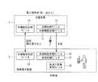
図1は、本発明による充電システムを採用した第1充電システムの構成例を示すブロック図である。同図において、本システムは、鉄道の駅や店舗などの電力提供者側に設けられる送電装置1と、利用者が持っている携帯電子装置2とを含んで構成されている。本システムでは、携帯電子装置2が、送電装置1により充電される。(Description of charging system)
FIG. 1 is a block diagram showing a configuration example of a first charging system employing a charging system according to the present invention. In this figure, this system includes a
送電装置1は、FeliCa(登録商標)リーダなどの非接触型処理モジュール13と、非接触型送電モジュール12と、送電制御モジュール11とを含んで構成されている。
携帯電子装置2は、FeliCa(登録商標)等の非接触型処理動作のための非接触型処理モジュール23と、充電のための非接触型受電モジュール22と、充電の判断と制御をする受電制御モジュール21と、高速に充電可能な大容量蓄電モジュール20とを含んで構成されている。The
The portable
(送電制御モジュールと受電制御モジュールの説明)
送電装置1内の送電制御モジュール11、及び、携帯電子装置2内の受電制御モジュール21は、相手が第1充電システムを備えていることを簡易に確認し、充電を行うモジュールである。
図2は、図1中の送電制御モジュール11、受電制御モジュール21のそれぞれの構成要素を示すブロック図である。
携帯電子装置2側の受電制御モジュール21は、外部装置の接近を検知するための接近検知機能211と、受電判断機能212と、充電判断用通信機能214と、受電装置制御機能213とを含んで構成されている。受電判断機能212は、接近している送電装置が第1の充電システムを備えていることを確認する機能である。実際の送電装置側との通信は、充電判断用通信機能214を介して行われ、実際の電力の受電は受電装置制御機能213を介して行われる。(Description of power transmission control module and power reception control module)
The power
FIG. 2 is a block diagram showing respective components of the power
The power
送電装置1側の送電制御モジュール11は、外部装置の接近を検知するための接近検知機能111と、送電判断機能112と、送電装置制御機能113、充電判断用通信機能114とを含んで構成されている。送電判断機能112は、接近している携帯電子装置が第1の充電システムを備えていることを確認する機能である。実際の携帯電子装置との通信は充電判断用通信機能114を介して行われ、実際の電力の送電は送電装置制御機能113を介して行われる。 The power
(充電フロー)
図3は、第1充電システムの処理を示すフローチャートであり、同図(a)は携帯電子装置側の処理を示し、同図(b)は送電装置側の処理を示している。
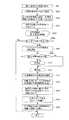
同図(a)において、携帯電子装置側の処理は、送電装置を検出した場合に開始される(ステップS301)。まず、充電処理の開始を送電装置と相互に確認する(ステップS302)。充電可能と判断された場合(ステップS303)、イベントが起こるまでの待機状態を経て(ステップS304)、装置同士が離れたか、又は、所定の時間が経過しタイムアウトになったか判断される(ステップS305)。その後、充電開始まで待機状態となり(ステップS306→S304→S305)。(Charging flow)
FIG. 3 is a flowchart showing processing of the first charging system. FIG. 3A shows processing on the portable electronic device side, and FIG. 3B shows processing on the power transmission device side.
In FIG. 9A, the process on the portable electronic device side is started when a power transmission device is detected (step S301). First, the start of the charging process is mutually confirmed with the power transmission device (step S302). When it is determined that charging is possible (step S303), after waiting for an event to occur (step S304), it is determined whether the devices have separated from each other, or whether a predetermined time has elapsed and timed out (step S305). ). Then, it will be in a standby state until charge start (step S306->S304-> S305).
充電開始と判断された場合、充電が行われる(ステップS307)。この充電は、送電装置から携帯電子装置が離れたことを検知するか、又は、充電が完了するまで行われる(ステップS308)。以上で処理は終了となる(ステップS309)。
なお、ステップS303において充電可能でないと判断された場合、処理はそのまま終了となる(ステップS303→S309)。ステップS305において装置同士が離れたか、又は、タイムアウトになった場合も同様である(ステップS303→S309)。When it is determined that charging is started, charging is performed (step S307). This charging is performed until it is detected that the portable electronic device is separated from the power transmission device or until the charging is completed (step S308). The process ends here (step S309).
If it is determined in step S303 that charging is not possible, the process ends as it is (step S303 → S309). The same applies when the devices are separated from each other in step S305 or time-out occurs (steps S303 → S309).
一方、同図(b)において、送電装置側の処理は、携帯電子装置を検出した場合に開始される(ステップS311)。まず、充電処理の開始を携帯電子装置と相互に確認する(ステップS312)。充電可能と判断された場合(ステップS313)、送電が開始される(ステップS314)。この送電は、送電装置から携帯電子装置が離れたことを検知するか、又は、充電が完了するまで行われる(ステップS315)。以上で処理は終了となる(ステップS316)。 On the other hand, in the same figure (b), the process by the side of a power transmission apparatus is started when a portable electronic device is detected (step S311). First, the start of the charging process is mutually confirmed with the portable electronic device (step S312). When it is determined that charging is possible (step S313), power transmission is started (step S314). This power transmission is performed until it is detected that the portable electronic device is separated from the power transmission device or until charging is completed (step S315). The process ends here (step S316).
なお、ステップS313において充電可能でないと判断された場合、処理はそのまま終了となる(ステップS313→S316)。
ところで、本システムにおいて、充電開始のきっかけは複数ある。例えば、送電装置が定期的にビーコンを送信し、携帯電子装置がそれに反応して充電開始要求を送出する場合や、送電装置と携帯電子装置がFeliCa(登録商標)などの非接触型処理を開始したことを検出し、携帯電子装置が充電開始要求を送出する場合もある。また逆に、送電装置側が携帯電子装置に対して充電開始要求をする場合もある。どちらの場合も、上述したように、携帯電子装置、送電装置の双方ともに、相手が第1充電システムを実装していることを確認し、充電処理の開始を確認する(上記ステップS302、S312)。If it is determined in step S313 that charging is not possible, the process ends as it is (steps S313 → S316).
By the way, in this system, there are a plurality of triggers for starting charging. For example, when the power transmission device periodically sends a beacon and the portable electronic device responds to it and sends a charge start request, or the power transmission device and the portable electronic device start non-contact processing such as FeliCa (registered trademark) In some cases, the portable electronic device sends a request to start charging. Conversely, the power transmission device may make a charge start request to the portable electronic device. In either case, as described above, both the portable electronic device and the power transmission device confirm that the other party has installed the first charging system and confirm the start of the charging process (steps S302 and S312 above). .
充電開始を確認できた場合は、上述したように、送電装置は送電を開始し(上記ステップS313)、携帯電子装置は充電を開始する(上記ステップS307)。確認できなかった場合は、送電装置もしくは携帯電子装置が第1充電システムを備えていないと判断し、充電を中止する(上記ステップS303→S309、ステップS313→S316)。
その後、携帯電子装置が離れたことを検知するか、一定の充電量に達した場合に、充電を終了する(上記ステップS308、ステップS315)。
以上により、携帯電子装置と送電装置との非接触型処理動作中に、同時に携帯電子装置の充電を行うことができる。When the start of charging can be confirmed, as described above, the power transmission device starts power transmission (step S313), and the portable electronic device starts charging (step S307). If it cannot be confirmed, it is determined that the power transmission device or the portable electronic device does not include the first charging system, and charging is stopped (steps S303 → S309, steps S313 → S316).
Thereafter, when it is detected that the portable electronic device is separated or when a certain amount of charge is reached, the charging is terminated (steps S308 and S315).
As described above, the portable electronic device can be charged simultaneously during the non-contact processing operation between the portable electronic device and the power transmission device.
(充電開始トリガの検知)
次に、充電開始トリガの検知方法について、図4〜図6を参照して説明する。これらの図には、送電装置1内の非接触型処理モジュール13、接近検知機能111、送電判断機能112、充電判断用通信機能114のそれぞれの動作と、携帯電子装置2内の非接触型処理モジュール23、接近検知機能211、受電判断機能212、充電判断用通信機能214のそれぞれの動作と、が示されている。(Charge start trigger detection)
Next, a method for detecting the charging start trigger will be described with reference to FIGS. In these figures, the operations of the
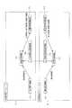
図4は送電装置が携帯電子装置の接近を検知し、非接触型処理モジュールと連携を行う場合の処理を示すシーケンス図である。同図において、非接触型処理モジュール13が接近を検知すると、接近検知信号が、接近検知機能111を介して、送電判断機能112に入力される(S2001、S2002)。送電判断機能112は、充電システムバージョン通知を含む充電開始要求を出力する(S2003)。この充電開始要求は、充電判断用通信機能114、充電判断用通信機能214を介して、受電判断機能212に送られる(S2004、S2005)。受電判断機能212では、受取った充電開始要求に含まれている充電システムのバージョンを見て、充電交渉可能か判断する(S2006)。 FIG. 4 is a sequence diagram illustrating processing when the power transmission device detects the approach of the portable electronic device and performs cooperation with the non-contact processing module. In the figure, when the
その後、受電判断機能212は、充電システムバージョン通知を含む充電開始応答を出力する(S2007)。この充電開始応答は、充電判断用通信機能214、充電判断用通信機能114を介して、送電判断機能112に送られる(S2008、S2009)。送電判断機能112では、受取った充電開始応答に含まれている充電システムのバージョンを見て、充電交渉可能か判断する(S2010)。 Thereafter, the power
図5は携帯電子装置が送電装置の接近を検知し、非接触型処理モジュールと連携を行う場合の処理を示すシーケンス図である。同図において、非接触型処理モジュール23が接近を検知すると、接近検知信号が、接近検知機能211を介して、受電判断機能212に入力される(S2101、S2102)。受電判断機能212は、充電システムバージョン通知を含む充電開始要求を出力する(S2103)。この充電開始要求は、充電判断用通信機能214、充電判断用通信機能114を介して、送電判断機能112に送られる(S2104、S2105)。送電判断機能112では、受取った充電開始要求に含まれている充電システムのバージョンを見て、充電交渉可能か判断する(S2106)。 FIG. 5 is a sequence diagram illustrating processing when the portable electronic device detects the approach of the power transmission device and cooperates with the non-contact processing module. In the figure, when the
その後、送電判断機能112は、充電システムバージョン通知を含む充電開始応答を出力する(S2107)。この充電開始応答は、充電判断用通信機能114、充電判断用通信機能214を介して、受電判断機能212に送られる(S2108、S2109)。受電判断機能212では、受取った充電開始応答に含まれている充電システムのバージョンを見て、充電交渉可能か判断する(S2110)。 Thereafter, the power
図6は非接触型処理モジュールと連携を行わずに、送電装置が携帯電子装置の接近を検知する場合の処理を示すシーケンス図である。同図において、送電装置1内の接近検知機能111は、携帯電子装置の接近を検知するためのポーリング信号を出力する(S2201)。このポーリング信号は、送電判断機能112に入力される。送電判断機能112は、充電システムバージョン通知を含む充電開始要求を出力する(S2202)。この充電開始要求は、充電判断用通信機能114を介して、充電判断用通信機能214に送られる(S2203)。以上の処理は、応答が返るまで、定期的に繰返し行われる。 FIG. 6 is a sequence diagram illustrating processing when the power transmission device detects the approach of the portable electronic device without performing cooperation with the non-contact processing module. In the figure, the
充電判断用通信機能214は、充電システムバージョン通知を含む充電開始要求を出力する(S2204)。この充電開始要求を受取った受電判断機能212は、接近通知信号を接近通知機能211へ出力する(S2205)。また、受電判断機能212は、受取った充電開始応答に含まれている充電システムのバージョンを見て、充電交渉可能か判断する(S2206)。 The charging
その後、受電判断機能212は、充電システムバージョン通知を含む充電開始応答を出力する(S2207)。この充電開始応答は、充電判断用通信機能214、充電判断用通信機能114を介して、送電判断機能112に送られる(S2208、S2209)。この充電開始応答を受取った送電判断機能112は、接近通知信号を接近通知機能111へ出力する(S2210)。また、送電判断機能112は、受取った充電開始応答に含まれている充電システムのバージョンを見て、充電交渉可能か判断する(S2111)。 Thereafter, the power
(装置同士が離れた場合の処理)
次に、充電開始後、装置同士が離れた場合の各機能間の処理について、図7を参照して説明する。同図には、送電装置1内の接近検知機能111、送電判断機能112、充電判断用通信機能114のそれぞれの動作と、携帯電子装置2内の接近検知機能211、受電判断機能212、充電判断用通信機能214のそれぞれの動作と、が示されている。(Processing when devices are separated)
Next, processing between the functions when the devices are separated from each other after the start of charging will be described with reference to FIG. In the figure, the operations of the
同図において、上述した充電開始トリガの検知シーケンス(図4〜図6のいずれかの1つの処理)が行われた後(S2300)、送電判断機能112は、任意で充電開始電力等の設定信号を出力する(S2301)。この設定信号は、充電判断用通信機能114、充電判断用通信機能214を介して、受電判断機能212に入力される(S2302、S2303)。 In the figure, after the above-described charge start trigger detection sequence (one of the processes in FIGS. 4 to 6) is performed (S2300), the power
受電判断機能212は、任意で電力等の応答信号を出力する(S2304)。この応答信号は、充電判断用通信機能214、充電判断用通信機能114を介して、送電判断機能112に入力される(S2305、S2306)。この応答信号を受取った送電判断機能112は、送電開始要求を送電装置制御機能113に出力する(S2307)。また、受電判断機能212は、受電装置制御機能213に、受電待機信号を出力する(S2308)。その後、送電装置制御機能113は、受電装置制御機能213に、送電を行う(S2309)。この送電により、電源すなわち高速大容量蓄電モジュールが充電される。 The power
充電中に、携帯電子装置2内の接近検知機能211、送電装置1内の接近検知機能111がそれぞれ相手と離れたことを検知すると(S2310、S2311)、離脱通知を、接近検知機能211から受電判断機能212に、接近検知機能111から送電判断機能112に、それぞれ出力する(S2312、S2313)。
その後、送電装置制御機能113は送電を停止し(S2315)、送電停止通知を送電判断機能112に出力する(S2316)。この送電停止通知には、任意で送電量通知が含められる。また、受電装置制御機能213は受電停止を検知し(S2317)、受電停止通知を受電判断機能212に出力する(S2318)。この受電停止通知には、任意で受電量通知が含められる。When it is detected that the
Thereafter, the power transmission
(充電フル状態になった場合の処理)
次に、充電開始後、充電フル状態になった場合の各機能間の処理について、図8を参照して説明する。同図には、送電装置1内の接近検知機能111、送電判断機能112、充電判断用通信機能114のそれぞれの動作と、携帯電子装置2内の接近検知機能211、受電判断機能212、充電判断用通信機能214のそれぞれの動作と、が示されている。(Processing when the battery is fully charged)
Next, processing between the functions when the charging is in a full state after the start of charging will be described with reference to FIG. In the figure, the operations of the
同図において、上述した充電開始トリガの検知シーケンス(図4〜図6のいずれかの1つの処理)が行われた後(S2300)、送電判断機能112は、任意で充電開始電力等の設定信号を出力する(S2401)。この設定信号は、充電判断用通信機能114、充電判断用通信機能214を介して、受電判断機能212に入力される(S2402、S2403)。 In the figure, after the above-described charge start trigger detection sequence (one of the processes in FIGS. 4 to 6) is performed (S2300), the power
受電判断機能212は、任意で電力等の応答信号を出力する(S2404)。この応答信号は、充電判断用通信機能214、充電判断用通信機能114を介して、送電判断機能112に入力される(S2405、S2406)。
その後、図7の場合と同様に、充電開始シーケンスが行われる(S2407)。
充電中に、携帯電子装置2内のが、高速大容量蓄電モジュールが充電フル状態になったことを検知すると(S2408)、接近検知機能211はバッテリフル信号を、受電判断機能212に出力する(S2409)。受電判断機能212からバッテリフル信号を受取った受電判断機能212は、送電停止要求を出力する(S2410)。この送電停止要求は、充電判断用通信機能214、充電判断用通信機能114、送電判断機能112を介して、送電装置制御機能113に入力される(S2411、S2412、S2413)。The power
Thereafter, as in the case of FIG. 7, a charge start sequence is performed (S2407).
During charging, when the portable
送電停止要求を受取った送電装置制御機能113は送電を停止し(S2414)、送電停止通知を送電判断機能112に出力する(S2415)。この送電停止通知には、任意で送電量通知が含められる。また、受電装置制御機能213は受電停止を検知し(S2416)、受電停止通知を受電判断機能212に出力する(S2417)。この受電停止通知には、任意で受電量通知が含められる。 The power transmission
なお、携帯電子装置2内の接近検知機能211、送電装置1内の接近検知機能111がそれぞれ相手と離れたことを検知すると(S2418、S2420)、離脱通知を、接近検知機能211から受電判断機能212に、接近検知機能111から送電判断機能112に、それぞれ出力する(S2419、S2421)。 When it is detected that the
(充電システムの説明)
図9は、本発明による充電システムを採用した、第1、2、3、4、5充電システムを包含する構成例を示すブロック図である。同図に示されている充電システムは、図1の構成に、携帯電話サービス提供会社など認証課金代行者側に設けられている認証課金代行装置3が追加された構成になっている。本システムでは携帯電子装置2が、送電装置1により充電され、必要に応じて認証課金代行装置3にて課金される。(Description of charging system)
FIG. 9 is a block diagram showing a configuration example including the first, second, third, fourth and fifth charging systems employing the charging system according to the present invention. The charging system shown in the figure has a configuration in which an authentication /
送電装置1は、FeliCa(登録商標)リーダなどの非接触型処理モジュール13と、非接触型送電モジュール12と、送電制御モジュール11とを含んで構成されている。
携帯電子装置2は、FeliCa(登録商標)等の非接触型処理動作のための非接触型処理モジュール23と、充電のための非接触型受電モジュール22と、充電の判断と制御をする受電制御モジュール21と、高速に充電可能な大容量蓄電モジュール20とを含んで構成されている。
認証課金代行装置3は、認証モジュール31と、課金モジュール32とを含んで構成されている。The
The portable
The authentication /
(送電制御モジュールと受電制御モジュールの説明)
送電装置1内の送電制御モジュール11、及び、携帯電子装置2内の受電制御モジュール21は、ポリシ内容や履歴情報などに基づいて充電の相手を識別し、場合により認証し、充電実行の判断を行うモジュールである。
図10は、図9中の送電制御モジュール11、受電制御モジュール21のそれぞれの構成要素を示すブロック図である。(Description of power transmission control module and power reception control module)
The power
FIG. 10 is a block diagram showing respective components of the power
携帯電子装置2側の受電制御モジュール21は、外部装置の接近を検知するための接近検知機能211と、受電判断機能212と、充電判断用通信機能214と、受電装置制御機能213と、充電判断用通信機能214と、利用者側ポリシ215と、入力機器制御機能218と、出力機器制御機能219と、認証課金代行装置用通信機能220とを含んで構成されている。なお、受電制御モジュール21には、利用者側ポリシ215と、利用者識別情報・携帯電子装置識別情報・認証情報・属性情報などの各情報216と、ポリシのバージョンや高速認証用鍵情報などの認証履歴情報217とが予め設定されている。 The power
送電装置1側の送電制御モジュール11は、外部装置の接近を検知するための接近検知機能111と、送電判断機能112と、送電装置制御機能113、充電判断用通信機能114と、入力機器制御機能118と、出力機器制御機能119と、認証課金代行装置用通信機能120とを含んで構成されている。なお、送電制御モジュール11には、電力提供者側ポリシ115と、電力提供者識別情報・送電装置識別情報・認証情報・属性情報などの各情報116と、ポリシのバージョンや高速認証用鍵情報などの認証履歴情報117とが予め設定されている。 The power
(携帯電子装置側受電制御モジュールの説明)
携帯電子装置2内の受電制御モジュール21は、必要に応じて利用者の識別情報、携帯電子装置の識別情報、認証情報(電子署名、PINコードなど)または属性情報(メーカ、通信事業者など)を用いて、利用者側ポリシ情報をもとに送電装置1からの受電可否を判断する。ただし、利用者側ポリシの一部を送電装置1に通知し、送電装置1内で一部の判断をすることもある。(Description of portable electronic device side power reception control module)
The power
また、本システムでは、認証時間を短縮するために、認証履歴情報に高速認証用鍵情報(後述)を保持しておく。この鍵情報を利用することにより、その有効期限内においては認証課金代行装置3へ認証を依頼することなく、認証を行うことができる。
利用者側ポリシの通知など、実際の送電装置側との通信は充電判断用通信機能214を介して行われ、実際の電力の受電は受電装置制御機能213を介して行われる。Further, in this system, in order to shorten the authentication time, fast authentication key information (described later) is held in the authentication history information. By using this key information, authentication can be performed without requesting authentication to the authentication /
Communication with the actual power transmission device side, such as notification of a user-side policy, is performed via the charging
本例において、基本的には利用者側ポリシに基づいて自動的に受電の判断が行われる。ただし、場合によっては入力機器制御機能218を介して明示的な利用者の意思を確認することが可能である。また、利用者側ポリシの入力も入力機器制御機能218を介して行われる。
利用者による受電容量や発生料金の確認、及び、利用者側ポリシの確認は、出力機器制御機能219を介して行われる。
また、認証課金代行装置3を利用する場合などで、受電量を外部へ通知する際には、認証課金代行装置用通信機能220が利用される。In this example, basically, power reception is automatically determined based on the user-side policy. However, in some cases, an explicit user's intention can be confirmed via the input
Confirmation of the power reception capacity and generated charges by the user and confirmation of the user-side policy are performed via the output
In addition, when the authentication /
(送電装置側送電制御モジュールの説明)
送電装置1側の送電制御モジュール11は、必要に応じて電力提供者の識別情報、送電装置の識別情報、認証情報(電子署名、PINコードなど)または属性情報(メーカ、通信事業者など)を用いて、電力提供者側ポリシ情報をもとに携帯電子装置2への送電可否を判断する。
また、本システムでは、認証時間を短縮するために、認証履歴情報に高速認証用鍵情報(後述)を保持しておく、この鍵情報を利用することにより、その有効期限内においては認証課金代行装置3へ認証を依頼することなく、認証を行うことができる。
実際の携帯電子装置との通信は充電判断用通信機能114を介して行われ、実際の電力の送電は送電装置制御機能113を介して行われる。(Description of power transmission device side power transmission control module)
The power
In addition, in this system, in order to shorten the authentication time, high-speed authentication key information (described later) is held in the authentication history information. By using this key information, the authentication / billing agent is used within the validity period. Authentication can be performed without requesting the
Communication with the actual portable electronic device is performed via the charging
本例において、基本的には電力提供者側ポリシに基づいて自動的に送電の判断が行われる。ただし、場合によっては入力機器制御機能118を介して明示的な電力提供者の意思を確認することが可能である。また、電力提供者側ポリシの入力も入力機器制御機能118を介して行われる。
電力提供者による送電や発生費用の確認および、電力提供者側ポリシの確認は、出力機器制御機能119を介して行われる。
また、認証課金代行装置3を利用する場合は、認証課金代行装置用通信機能120を介して認証を依頼する。In this example, basically, the determination of power transmission is automatically made based on the power provider side policy. However, in some cases, it is possible to confirm the intention of the explicit power provider via the input
Confirmation of power transmission and generated costs by the power provider and confirmation of the power provider side policy are performed via the output
When the authentication /
(認証課金代行装置)
図11は、図9中の認証課金代行装置3の構成例を示すブロック図である。
同図において、認証課金代行装置3は、高速認証用鍵情報発行機能311と、携帯電子装置認証機能312と、送電装置認証機能313と、認証記録保存機能314とを含む認証モジュール31と、課金機能321を含む課金モジュール32と、送電装置側に設けられている送電制御モジュール11との間の通信を制御する送電装置側通信機能33と、携帯電子装置側に設けられている受電制御モジュール21との間の通信を制御する携帯電子装置側通信機能34とを含んで構成されている。(Authentication / billing agent)
FIG. 11 is a block diagram showing a configuration example of the authentication /
In the figure, an authentication /
この認証課金代行装置3は、利用者又は携帯電子装置の識別情報と認証情報(上記の携帯電子装置認証機能312)、電力提供者又は送電装置の識別情報と認証情報(上記の送電装置認証機能313)を持ち、各装置について認証を行うことができる。これらの情報は、通常は携帯電子装置の認証に利用されるが、携帯電子装置が送電装置の認証を行う場合にも利用できる。 The authentication /
また、認証課金代行装置3は、携帯電子装置の利用者および送電装置を使う電力提供者の情報を持つため、携帯電子装置の受電量や送電装置の送電量などをもとに利用者へ課金することができる。
携帯電子装置2や送電装置1は、各ポリシによって厳密な代行認証や代行課金を必要とする場合に認証課金代行装置3を利用することができる。
そのほか、次回の認証を短縮化するために、高速認証用鍵情報発行機能311によって高速認証用鍵情報を発行し、それを送電装置1と携帯電子装置2へ配布できる。つまり、正常に認証が終了した場合、次回以降に代行装置での認証が不要になるように高速認証用鍵情報を発行し、この情報を用いて高速認証処理を実現する。Further, since the authentication /
The portable
In addition, in order to shorten the next authentication, the high-speed authentication key
また、ここでは非接触型処理モジュール(Ferica(登録商標)など)における作業と、充電における作業において、認証を独立して扱っているが、非接触型処理モジュールでの作業の中で認証・課金が行われる場合、それと充電の認証・課金を独立させずに共用し、充電目的の認証・課金のフローを省略する場合もある。以下、独立して認証・課金を行う場合について説明する。 Also, here, authentication is handled independently in the work in the non-contact type processing module (Ferica (registered trademark), etc.) and the work in the charging, but authentication / billing is performed in the work in the non-contact type processing module. In some cases, authentication and charging for charging and charging are shared independently of each other and the authentication and charging flow for charging is omitted. Hereinafter, a case where authentication / billing is performed independently will be described.
(利用者側ポリシ)
利用者側ポリシには、料金設定、課金方式設定、充電方式設定、充電判断設定、セキュリティ設定の、5つの主要な分類がある。それぞれの分類の設定項目について説明する。
料金設定には、許容充電料金設定(例えば、無料/1秒あたりn円以下/1ワットあたりn円以下なら充電)や、特典付き料金設定(例えば、無料/n円以下なら広告付きでもよい)などがある。
課金方式設定には、代理課金装置を利用した方法や、電子マネーによる即時決済などが選択できる。(User policy)
There are five main categories of user-side policies: fee setting, charging method setting, charging method setting, charging determination setting, and security setting. The setting items for each classification will be described.
Charges can be set with an acceptable charge rate (for example, free / less than n yen per second / charged if less than n yen per watt), or with a fee (for example, free / less than n yen may be accompanied by an advertisement) and so on.
For the billing method setting, a method using a proxy billing device or an immediate settlement using electronic money can be selected.
充電方式設定には、受信可能電力の強さや、1回あたりの受信可能電力量を設定することが可能である。
充電判断設定には、そもそもポリシによる自動充電を行うかどうかの自動充電の可否設定や、月々の費用の上限設定、電力提供者の限定、送電装置の限定、属性情報による限定などの設定が可能なほか、利用者に明示的に許諾を得る設定も可能である。In the charging method setting, it is possible to set the strength of receivable power and the receivable power amount per time.
In the charging judgment setting, you can set whether to automatically charge according to the policy, whether to perform automatic charging, the upper limit of monthly expenses, the limitation of power providers, the limitation of power transmission devices, the limitation by attribute information, etc. In addition, it is possible to explicitly obtain permission from the user.
セキュリティ設定では、利用者情報のそれぞれに対する通知/非通知設定が可能である。利用者情報とは、利用者の識別情報、携帯電子装置の識別情報、属性情報(メーカ、通信事業者など)を指す。また、利用者側ポリシの一部分(料金設定、課金方式設定、充電方式設定など)の通知/非通知設定が可能である。さらに、高速認証(認証課金代行装置への認証を省略する仕組み)システムの利用を許可するための設定もある。
なお、上記の設定以外にも、任意の項目及び値を設定できる。In the security setting, notification / non-notification for each piece of user information can be set. User information refers to identification information of a user, identification information of a portable electronic device, and attribute information (manufacturer, communication carrier, etc.). Also, notification / non-notification setting of a part of the user side policy (charge setting, charging method setting, charging method setting, etc.) can be performed. Furthermore, there is a setting for permitting the use of a high-speed authentication (a mechanism for omitting authentication to the authentication / billing proxy device) system.
In addition to the above settings, arbitrary items and values can be set.
(電力提供者側ポリシ)
電力提供者側ポリシには、料金設定、課金方式設定、充電方式設定、充電判断設定、セキュリティ設定の、5つの主要な分類がある。それぞれの分類の設定項目について説明する。
料金設定には、充電料金設定(例えば、無料/1秒あたりn円/1ワットあたりn円)や、特典付き料金設定(例えば、広告付きで無料/n円)、時間変化料金設定(例えば、最初1秒は無料で次から1秒あたりn円)などがある。また、利用者ごとや携帯電子装置ごとの個別料金設定(例えば、利用回数の多い利用者/携帯電子装置は割り引く)や、携帯電子装置の属性情報(メーカ、通信事業者など)ごとの個別料金設定(例えば、特定メーカや特定通信業者の携帯電話は割り引く)などの設定も可能である。(Power supplier policy)
There are five main categories of power provider side policies: charge setting, charging method setting, charging method setting, charging determination setting, and security setting. The setting items for each classification will be described.
Charge settings include charging charge settings (for example, free / n yen per second / n yen per watt), price settings with benefits (for example, free with advertisement / n yen), time-varying charge settings (for example, The first one is free and the next is n yen per second). In addition, individual fee settings for each user and each portable electronic device (for example, discounts for users / mobile electronic devices with many uses) and individual fees for each attribute information (manufacturer, carrier, etc.) of the portable electronic device Settings such as setting (for example, discounting mobile phones of specific manufacturers and specific communication companies) are also possible.
課金方式設定には、代理課金装置を利用した方法や、電子マネーによる即時決済などを許容するかどうかが設定できる。
充電方式設定には、携帯電子装置が送電装置と充電交渉を開始したときに、充電に関する認証に時間が掛かる場合などがあり、認証の前から先行して充電を開始するかどうかを設定することが可能である。また、送信可能電力の強さや、1回あたりの送信可能電力量を設定することが可能である。
充電判断設定には、そもそもポリシによる自動充電を行うかどうかの自動充電の可否設定や、無料電力提供時などにおける月々の費用の上限設定、利用者の限定、携帯電子装置の限定、属性情報(メーカや通信事業者など)による限定、などの設定が可能なほか、電力提供者に明示的に許諾を得る設定も可能である。In the billing method setting, it is possible to set a method using a proxy billing device or whether to allow instant payment using electronic money.
In the charging method setting, when the mobile electronic device starts charging negotiations with the power transmission device, it may take time for authentication related to charging. Set whether to start charging ahead of authentication. Is possible. It is also possible to set the strength of transmittable power and the transmittable power amount per time.
The charge determination settings include whether to automatically charge according to the policy, whether to perform automatic charging, the upper limit of monthly expenses when free power is provided, user restrictions, portable electronic device restrictions, attribute information ( The setting can be limited by a manufacturer, a communication carrier, etc.), or a setting can be explicitly obtained from a power provider.
セキュリティ設定では、電力提供者情報のそれぞれに対する通知/非通知設定が可能である。電力提供者情報とは、電力提供者の識別情報、送電装置の識別情報、属性情報を指す。また、電力提供者側ポリシの一部分(料金設定、課金方式設定、充電方式設定など)の通知/非通知設定が可能である。さらに、高速認証(認証課金代行装置への認証を省略する仕組み)システムの利用を許可するための設定もある。
なお、上記の設定以外にも、任意の項目及び値を設定できる。In the security setting, notification / non-notification setting for each of the power provider information is possible. The power provider information refers to power provider identification information, power transmission device identification information, and attribute information. Also, notification / non-notification setting of a part of the power provider side policy (charge setting, charging method setting, charging method setting, etc.) can be performed. Furthermore, there is a setting for permitting the use of a high-speed authentication (a mechanism for omitting authentication to the authentication / billing proxy device) system.
In addition to the above settings, arbitrary items and values can be set.
(充電フロー)
以下、本実施例における充電フローについて説明する。
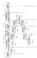
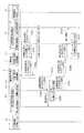
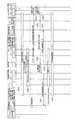
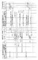
図12は、第2充電システムの処理を示すシーケンス図である。また、図13は携帯電子装置の処理を示すフローチャート、図14は携帯電子装置側の第1次充電判断処理を示すフローチャートである。図15は送電装置の処理を示すフローチャートである。図16は、送電装置側の第1次充電判断処理を示すフローチャートである。図17は、送電装置側の認証処理を示すフローチャートである。図18は、送電装置側の課金処理を示すフローチャートである。図19は認証課金代行装置での認証処理を示すフローチャート、図20は認証課金代行装置での課金処理を示すフローチャートである。
処理の大まかな流れは以下の通りである。すなわち、装置双方が利用者情報・利用者側ポリシのバージョンや、電力提供者情報・電力提供者側ポリシのバージョンを通知し合い、それにより双方が第1次充電判断を行う。その後、認証や課金などを含めた第2次充電判断を電力提供者側で行い、充電が行われる。(Charging flow)
Hereinafter, the charging flow in the present embodiment will be described.
FIG. 12 is a sequence diagram showing processing of the second charging system. FIG. 13 is a flowchart showing processing of the portable electronic device, and FIG. 14 is a flowchart showing primary charging determination processing on the portable electronic device side. FIG. 15 is a flowchart showing processing of the power transmission device. FIG. 16 is a flowchart illustrating the primary charging determination process on the power transmission device side. FIG. 17 is a flowchart illustrating authentication processing on the power transmission device side. FIG. 18 is a flowchart illustrating a charging process on the power transmission apparatus side. FIG. 19 is a flowchart showing authentication processing in the authentication / billing proxy device, and FIG. 20 is a flowchart showing charging processing in the authentication / billing proxy device.
The general flow of processing is as follows. That is, both devices notify each other of the user information / user policy version and the power provider information / power provider policy version, thereby making the primary charging determination. Thereafter, secondary charging determination including authentication and billing is performed on the power provider side, and charging is performed.
以下、より具体的に説明する。図12において、最初に、送電装置1と携帯電子装置2との間で、相互に装置を検出すると、充電処理の開始を確認する(ステップS701)。充電処理を行う場合、送電装置1から携帯電子装置2に、電力提供者情報、及び、利用者側ポリシの問い合わせが送信される(ステップS702)。「電力提供者情報」には、電力提供者識別情報、送電装置識別情報、属性情報、電力提供者ポリシのバージョン、が含まれている。以降の説明においても同様である。 More specific description will be given below. In FIG. 12, first, when a device is detected between the
次に、携帯電子装置2では、携帯電子装置側の第1次充電判断が行われる(ステップS703)。ここでは、ポリシのバージョンがチェックされる。そして、携帯電子装置2から送電装置1に、利用者情報、及び、利用者側ポリシが通知される(ステップS704)。「利用者情報」には、利用者識別情報、携帯電子装置識別情報、属性情報、利用者ポリシのバージョン、が含まれている。以降の説明においても同様である。 Next, in the portable
ステップS704の通知を受取った送電装置1では、送電装置側の第1次充電判断が行われる(ステップS705)。第1次充電判断の結果、場合によって先行充電が開始される(ステップS706)。なお、場合によっては、ステップS704において利用者側ポリシの送信を省略し、ステップS705においてポリシの照合処理を省略してもよい。
次に、送電装置1側で第2次充電判断が行われ、その後、送電装置1と携帯電子装置2との間で、認証情報などの問い合わせ及びそれに対する通知の授受が行われる(ステップS708a、S708b)。なお、その問い合わせ及び通知の代わりに、高速認証を行っても良い。In the
Next, the secondary charging determination is performed on the
その後、場合により、送電装置1から認証課金代行装置3に代行認証要求が送信され(ステップS709a)、認証課金代行装置3から送電装置1に認証結果が通知される(ステップS709b)。
次に、送電装置1において課金判断が行われる(ステップS710)。このとき、場合により、電子マネーによって決済される(ステップS711)。その後、送電装置1から携帯電子装置2に、充電実施内容が通知され、充電が開始される(ステップS712)。なお、場合により、広告配信が行われる(ステップS713)。また、場合により、高速認証用鍵情報の取得又は更新処理(ステップS714a)、高速認証用鍵情報の配布(ステップS714b)、高速認証用鍵情報の転送(ステップS714c)が行われる。Thereafter, in some cases, the
Next, the charging determination is performed in the power transmission device 1 (step S710). At this time, in some cases, settlement is made with electronic money (step S711). Thereafter, the
送電装置1から携帯電子装置2への充電は、装置同士が離れたことを検知するか、充電が完了した場合に終了となる(ステップS715a、S715b)。
充電が終了した場合、認証課金代行装置3による課金が行われる(ステップS717)。このとき、場合により、送電装置1から認証課金代行装置3に、送電量が通知される(ステップS716)。また、場合により、携帯電子装置2から認証課金代行装置3に、受電量が通知される(ステップS718)。場合により、定期的な料金の支払いが行われる(ステップS719、S720)。Charging from the
When the charging is completed, charging by the authentication /
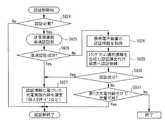
図13において、携帯電子装置側の処理は、送電装置を検出した場合に開始される(ステップS801)。まず、充電処理の開始を送電装置と相互に確認する(ステップS802)。その後、電力者提供装置から電力提供者情報を通知され、利用者情報と利用者ポリシの問い合わせを受ける(ステップS803)。そして、携帯電子装置側の第1次充電判断部の判断処理に移行する(ステップS804)。 In FIG. 13, the process on the portable electronic device side is started when a power transmission device is detected (step S801). First, the start of the charging process is mutually confirmed with the power transmission device (step S802). Thereafter, the power provider information is notified from the power provider device and receives an inquiry about the user information and the user policy (step S803). And it transfers to the judgment process of the primary charge judgment part by the side of a portable electronic device (step S804).
携帯電子装置側の第1次充電判断部の判断処理が図14に示されている。同図において、認証履歴情報に履歴があり、ポリシのバージョンが一致するか判断される(ステップS823)。この判断の結果、バージョンが一致する場合、前回の第1次充電判断結果を採用する(ステップS824)。一方、バージョンが一致しない場合、利用者側ポリシの充電判断設定と電力提供者情報とを照合し、その結果を第1次判断とする(ステップS825)。 The determination process of the primary charge determination unit on the portable electronic device side is shown in FIG. In the figure, it is determined whether there is a history in the authentication history information and the policy versions match (step S823). If the versions match as a result of this determination, the previous primary charge determination result is adopted (step S824). On the other hand, if the versions do not match, the charging determination setting of the user side policy is compared with the power provider information, and the result is set as the primary determination (step S825).
図13に戻り、第1次充電判断で充電不可と判断されなければ、セキュリティ設定に基づき、利用者情報と利用者ポリシの一部を通知する(ステップS805→S806)。そして、電力提供者側のポリシによって先行充電が開始される(ステップS807)。
その後、イベントが起こるまで待機状態となる(ステップS808)。待機状態において、認証情報の要求があった場合、認証情報を通知する(ステップS809→S810)。符号化情報を受信した場合、携帯電子装置側の高速認証部による処理に移行する(ステップS811→S812)。この高速認証部による処理については後述する。Returning to FIG. 13, if it is not determined that charging is impossible in the primary charging determination, the user information and a part of the user policy are notified based on the security setting (steps S805 to S806). Then, advance charging is started by the policy on the power provider side (step S807).
Thereafter, the system stands by until an event occurs (step S808). When there is a request for authentication information in the standby state, the authentication information is notified (steps S809 → S810). When the encoded information is received, the process proceeds to processing by the high-speed authentication unit on the portable electronic device side (steps S811 → S812). The processing by the high-speed authentication unit will be described later.
電子マネー残高の照会があった場合、電子マネー残額を通知する(ステップS813→S814)。電子マネー決済の要求があった場合、電子マネー決済処理を行う(ステップS815→S816)。
充電実施内容を受信した場合には、充電処理に移行する(ステップS817→S818)。なお、充電処理においては、同時に、高速認証用鍵情報を受信することができる。携帯電子装置が送電装置から離れたことを検知するか、充電が完了したら、受電量を計算する(ステップS819)。代行課金の場合で通信可能な場合、認証課金代行装置へ受電量を通知し(ステップS820)、処理は終了となる(ステップS821)。When the electronic money balance is inquired, the remaining amount of electronic money is notified (steps S813 → S814). When there is a request for electronic money settlement, electronic money settlement processing is performed (steps S815 → S816).
When the charge execution content is received, the process proceeds to the charge process (steps S817 → S818). In the charging process, the high-speed authentication key information can be received simultaneously. When it is detected that the portable electronic device is separated from the power transmission device or charging is completed, the amount of received power is calculated (step S819). If communication is possible in the case of proxy billing, the amount of power received is notified to the authentication / billing proxy device (step S820), and the process ends (step S821).
また、装置同士が離れたか、又は、所定の時間が経過しタイムアウトになったか判断され(ステップS822)、それらの場合には処理は終了となる(ステップS822→S821)。なお、ステップS805において、充電不可と判断された場合も、処理は終了となる(ステップS805→S821)。
図15において、送電装置側の処理は、携帯電子装置を検出した場合に開始される(ステップS901)。まず、充電処理の開始を携帯電子装置と相互に確認する(ステップS902)。そして、携帯電子装置に電力提供者情報を通知し、利用者情報及び利用者ポリシを問い合わせる(ステップS903)。その後、携帯電子装置から利用者情報及び利用者ポリシを受取る(ステップS904)。そして、送電装置側の第1次充電判断部の判断処理に移行する(ステップS905)。Further, it is determined whether the devices are separated from each other, or whether a predetermined time has elapsed and timed out (step S822), and in those cases, the process ends (step S822 → S821). If it is determined in step S805 that charging is not possible, the process ends (steps S805 → S821).
In FIG. 15, the process on the power transmission device side is started when a portable electronic device is detected (step S901). First, the start of the charging process is mutually confirmed with the portable electronic device (step S902). Then, power provider information is notified to the portable electronic device, and user information and user policy are inquired (step S903). Thereafter, user information and a user policy are received from the portable electronic device (step S904). And it transfers to the judgment process of the primary charge judgment part by the side of a power transmission apparatus (step S905).
送電装置側の第1次充電判断部の判断処理が図16に示されている。同図において、相手側が充電不可と判断したか判断し、そうであれば充電不可と判断する(ステップS916→S917)。認証履歴情報に履歴があり、ポリシのバージョンが前回と一致すれば、前回の第1次充電結果を採用する(ステップS918→S919)。
相手側が充電不可と判断しておらず、かつ、ポリシのバージョンが前回と一致しなければ、電力提供者側ポリシの充電判断設定と利用者情報とを照合する(ステップS916→S918→S920)。この照合の結果、充電不可であれば、充電不可と判断する(ステップS921→S922)。そうでなければ、双方のポリシの料金設定と課金方式設定とを照合し、その結果を第1次充電判断とする(ステップS921→S923)。The determination process of the primary charge determination unit on the power transmission apparatus side is shown in FIG. In the figure, it is determined whether the other party has determined that charging is not possible, and if so, it is determined that charging is not possible (steps S916 → S917). If there is a history in the authentication history information and the policy version matches the previous one, the previous primary charging result is adopted (steps S918 → S919).
If the other party does not determine that charging is not possible and the policy version does not match the previous version, the charging determination setting of the power provider side policy and the user information are collated (steps S916 → S918 → S920). If the result of this collation is that charging is not possible, it is determined that charging is not possible (step S921 → S922). Otherwise, the charge setting of both policies and the charging method setting are collated, and the result is set as the primary charge determination (step S921 → S923).
図15に戻り、第1次充電判断で充電不可とされたか判断し(ステップS906)、そうでなればポリシにより先行充電が開始され、その旨が携帯電子装置に通知される(ステップS906→S907)。その後、第2次充電判断が必要であるか判断される(ステップS908)。第2次充電判断が必要である場合、認証部による認証処理に移行する(ステップS909)。 Returning to FIG. 15, it is determined whether or not charging is impossible in the primary charging determination (step S906). If this is not the case, advance charging is started by the policy, and that is notified to the portable electronic device (steps S906 → S907). ). Thereafter, it is determined whether secondary charging determination is necessary (step S908). When the secondary charging determination is necessary, the process proceeds to an authentication process by the authentication unit (step S909).
認証部による認証処理が図17に示されている。同図において、最初に、認証処理が必要かどうか判断し(ステップS924)、必要な場合は送電装置側の高速認証部による高速認証が行われる(ステップS925)。
高速認証に成功した場合、認証情報に基づいた充電実施内容を選定する(ステップS926→S927)。この充電実施内容には、例えば個人別のサービスなどが考えられる。The authentication process by the authentication unit is shown in FIG. In the figure, first, it is determined whether or not authentication processing is necessary (step S924), and if necessary, high-speed authentication is performed by the high-speed authentication unit on the power transmission device side (step S925).
When the high-speed authentication is successful, the charging implementation content based on the authentication information is selected (steps S926 → S927). For example, an individual service may be considered as the content of the charging.
一方、高速認証に成功しなかった場合、携帯電子装置の認証情報を取得する(ステップS926→S928)。そして、トランザクション識別情報を生成し、認証課金代行装置へ認証依頼を行う(ステップS929)。この認証に成功した場合、上記のステップS927と同様の処理に移行する(ステップS930→S927)。これに対し、認証に成功しなかった場合、第1次充電判断だけで充電可能か判断し(ステップS931)、処理は終了となる。 On the other hand, if the high-speed authentication is not successful, the authentication information of the portable electronic device is acquired (steps S926 → S928). Then, transaction identification information is generated and an authentication request is made to the authentication / billing proxy device (step S929). If the authentication is successful, the process proceeds to the same process as in step S927 (step S930 → S927). On the other hand, if the authentication is not successful, it is determined whether charging is possible only by the primary charging determination (step S931), and the process ends.
図15に戻り、第2次充電判断が必要でない場合、又は、認証部による認証処理が終了した場合、課金部による課金処理に移行する(ステップS910)。課金部による課金処理が図18に示されている。同図において、最初に、課金処理が必要かどうか判断し(ステップS932)、必要な場合は次に電子マネー決済が必要か判断する(ステップS933)。 Returning to FIG. 15, when the secondary charging determination is not necessary, or when the authentication process by the authentication unit is completed, the process proceeds to the charging process by the charging unit (step S910). The accounting process by the accounting unit is shown in FIG. In the figure, first, it is determined whether or not billing processing is necessary (step S932), and if necessary, it is next determined whether or not electronic money settlement is necessary (step S933).
電子マネー決済が必要な場合、電子マネーの残額を照会する(ステップS933→S937)。この照会の結果、電子マネー決済が可能であれば、電子マネー決済の場合の充電実施内容を選定する(ステップS938→S939)。この充電実施内容には、例えば料金の設定などが考えられる。その後、電子マネーによる決済が行われ(ステップS933)、処理は終了となる。 When electronic money settlement is necessary, the remaining amount of electronic money is inquired (steps S933 → S937). If the result of this inquiry is that electronic money payment is possible, the contents of charge implementation in the case of electronic money payment are selected (steps S938 → S939). For example, a charge may be set as the content of the charging. Thereafter, settlement with electronic money is performed (step S933), and the process ends.
一方、ステップS937の照会の結果、電子マネー決済が不可である場合や、電子マネーによる決済が必要ない場合、認証済みで代行課金が可能か判断される(ステップS934)。代行課金が可能であれば、代行課金の場合の充電実施内容を選定する(ステップS934→S935)。この充電実施内容には、例えば料金の設定などが考えられる。その後、処理は終了となる。 On the other hand, as a result of the inquiry in step S937, if electronic money payment is not possible or if payment by electronic money is not required, it is determined whether proxy billing is already possible (step S934). If proxy billing is possible, the contents of charging for proxy billing are selected (steps S934 → S935). For example, a charge may be set as the content of the charging. Thereafter, the process ends.
代行課金が不可であれば、先行充電の中止などの処理が行われ(ステップS934→S936)、処理は終了となる。
図15に戻り、充電開始の旨と共に、上記の充電実施内容が携帯電子装置に通知される(ステップS910→S911)。その後、充電が行われる(ステップS912)。充電中には、必要に応じて広告配信や、高速認証用鍵情報の取得処理、その転送が行われる。
送電装置から携帯電子装置が離れたことを検知した場合、又は、充電が完了した場合、送電量を計算する(ステップS913)。そして、必要に応じて、ポイント加算などの特典を与える(ステップS914)。代行課金の場合、認証課金代行装置へ送電量を通知する(ステップS915)。If proxy billing is not possible, processing such as cancellation of pre-charging is performed (steps S934 → S936), and the processing ends.
Returning to FIG. 15, together with the fact that charging is started, the above-described charging content is notified to the portable electronic device (steps S <b> 910 → S <b> 911). Thereafter, charging is performed (step S912). During charging, advertisement distribution, high-speed authentication key information acquisition processing, and transfer thereof are performed as necessary.
When it is detected that the portable electronic device is separated from the power transmission device, or when charging is completed, a power transmission amount is calculated (step S913). Then, as necessary, a privilege such as point addition is given (step S914). In the case of proxy billing, the amount of power transmission is notified to the authentication billing proxy device (step S915).
図19において、認証課金代行装置での認証処理は、以下のように行われる。送電装置からトランザクション識別情報を通知されるか、利用者又は携帯電子装置の識別情報の認証要求が入力された場合に、認証課金代行装置での認証処理が開始される(ステップS1001)。最初に、認証情報をもとに正当性を判断する(ステップS1002)。次に、送電装置識別情報とトランザクション識別情報と認証結果を記録する(ステップS1003)。最後に、認証結果を送電装置へ通知する(ステップS1004)。 In FIG. 19, the authentication processing in the authentication / billing proxy device is performed as follows. When the transaction identification information is notified from the power transmission device or the authentication request for the identification information of the user or the portable electronic device is input, the authentication processing in the authentication / billing proxy device is started (step S1001). First, the validity is determined based on the authentication information (step S1002). Next, the power transmission device identification information, the transaction identification information, and the authentication result are recorded (step S1003). Finally, the authentication result is notified to the power transmission apparatus (step S1004).
図20において、認証課金代行装置での課金処理は、以下のように行われる。送電装置からトランザクション識別情報と送電量とが通知された場合に、認証課金代行装置での課金処理が開始される(ステップS1101)。最初に代行課金を行うか判断され(ステップS1102)、代行課金を行わない場合、そのまま処理は終了となる。
代行課金を行う場合、携帯電子装置側からも受電量の通知があるか判断される(ステップS1103)。その通知があった場合は、送電量、受電量、契約形態をもとに課金計算される(ステップS1103→S1104)。その後、認証記録と照合し、課金サーバへ記録される(ステップS1104→S1105)。In FIG. 20, the charging process in the authentication / billing proxy device is performed as follows. When the transaction identification information and the amount of power transmission are notified from the power transmission device, the charging process in the authentication / billing proxy device is started (step S1101). First, it is determined whether or not proxy charging is to be performed (step S1102), and if proxy charging is not performed, the process ends.
When performing proxy billing, it is determined whether there is a notification of the amount of power received from the portable electronic device (step S1103). If there is a notification, billing is calculated based on the amount of power transmitted, the amount of power received, and the contract form (steps S1103 → S1104). Thereafter, it is verified against the authentication record and recorded in the billing server (steps S1104 → S1105).
携帯電子装置側から受電量の通知が無い場合は、送電量、契約形態をもとに課金計算される(ステップS1103→S1107)。その後、認証記録と照合し、課金サーバへ記録される(ステップS1107→S1105)。
最後に、電力提供者側へ代金が支払われ、利用者側へ代金請求が行われる(ステップS1106)。If there is no notification of the amount of power received from the portable electronic device side, the charge is calculated based on the amount of power transmission and the contract form (steps S1103 → S1107). Thereafter, it is verified against the authentication record and recorded in the billing server (steps S1107 → S1105).
Finally, the price is paid to the power provider side, and the user side is charged (step S1106).
以上、図12〜図20を参照して説明した各装置の処理により、本システムにおいて実現できる処理は以下の通りである。
充電開始のきっかけは複数ある。送電装置が定期的にビーコンを送信し、携帯電子装置がそれに反応して充電開始要求を送出する場合や、送電装置と携帯電子装置がFeliCa(登録商標)などの非接触型処理を開始したことを検出し、携帯電子装置が充電開始要求を送出する場合もある。また逆に、送電装置側が携帯電子装置に対して充電開始要求をする場合もある。どちらの場合も、携帯電子装置と送電装置の双方が充電処理の開始を確認する(図12のステップS701)。The processing that can be realized in the present system by the processing of each device described with reference to FIGS. 12 to 20 is as follows.
There are several reasons for starting charging. When the power transmission device periodically transmits a beacon and the mobile electronic device responds to it and sends a charge start request, or the power transmission device and the mobile electronic device start non-contact processing such as FeliCa (registered trademark) In some cases, the portable electronic device sends a charge start request. Conversely, the power transmission device may make a charge start request to the portable electronic device. In either case, both the portable electronic device and the power transmission device confirm the start of the charging process (step S701 in FIG. 12).
その後、送電装置側から電力提供者情報(電力提供者の識別情報、送電装置の識別情報、属性情報)と電力提供者側ポリシのバージョンを通知され、利用者情報(利用者の識別情報、携帯電子装置の識別情報、属性情報)と利用者側ポリシの問い合わせを受ける(図12のステップS702)。
携帯電子装置は、利用者側ポリシに記述された充電判断設定に基づき電力提供者情報と電力提供者側ポリシのバージョンを照合し、利用者側の充電の第1次充電判断を行う。ここでの判断項目は、利用者側ポリシの充電判断設定にある、自動充電の可否、月々の費用の上限、電力提供者の限定、送電装置の限定、利用者の明示的な許諾、などである(図12のステップS703)。Thereafter, the power transmission device side is notified of the power provider information (power provider identification information, power transmission device identification information, attribute information) and the power provider policy version, and the user information (user identification information, portable information) The electronic device identification information and attribute information) and the user policy inquiry are received (step S702 in FIG. 12).
The portable electronic device collates the power provider information with the version of the power provider side policy based on the charging determination setting described in the user side policy, and performs the primary charging determination of charging on the user side. Judgment items here include whether or not automatic charging is possible, the upper limit of monthly expenses, the limitation of the power provider, the limitation of the power transmission device, the explicit permission of the user, etc. Yes (step S703 in FIG. 12).
前回に同じ送電装置で充電を行っており、その認証履歴情報を保持している場合で、そのときの利用者側ポリシのバージョンと電力提供者側ポリシのバージョンとが一致しているとき(バージョン一致時)に、第1次充電判断を省略し、前回の第1次充電判断の結果を適用することができる。
携帯電子装置は、第1次充電判断で充電不可と判断した場合、そこで充電作業は終了する。充電不可と判断しなかった場合は、セキュリティ設定に基づき、利用者情報の全てまたは一部と利用者側ポリシのバージョンを選択的に送電装置へ通知する。バージョン一致時の場合は、その旨も通知する。
バージョン一致時でない場合は、利用者側ポリシのうち、料金設定・課金方式設定・充電方式設定について、送電装置へ通知する(図12のステップS704)。When charging was performed with the same power transmission device last time and the authentication history information was retained, and the version of the user-side policy and the version of the power provider-side policy match (version At the time of coincidence), the primary charge determination can be omitted, and the result of the previous primary charge determination can be applied.
If the portable electronic device determines that charging is not possible in the primary charging determination, the charging operation ends there. If it is not determined that charging is not possible, all or part of the user information and the version of the user-side policy are selectively notified to the power transmission device based on the security setting. If there is a version match, this is also notified.
If the versions are not coincident, the power transmission apparatus is notified of the charge setting / charging method setting / charging method setting in the user-side policy (step S704 in FIG. 12).
送電装置では、電力提供者側ポリシに記述された充電判断設定に基づき利用者情報を照合し、充電の判断を行う。ここでの判断項目は、電力提供者側ポリシの充電判断設定にある、自動充電の可否、無料提供時などにおける月々の費用の上限、利用者の限定、携帯電子装置、属性情報(メーカや通信事業者など)による限定、電力提供者の明示的な許諾、などである。その後、電力提供者側ポリシと利用者側ポリシの利用金設定および課金方式設定を照合して充電の判断を行い、その結果を第1次充電判断とする(図12のステップS705)。バージョン一致の通知を受けた場合は、電力提供者側での第1次充電判断を省略し、前回の第1次充電判断の結果を適用することができる。 In the power transmission device, the user information is collated based on the charging determination setting described in the power provider side policy, and the charging is determined. The judgment items here are the charging judgment settings of the power provider side policy, whether or not automatic charging is possible, the upper limit of monthly expenses at the time of free provision, etc., user restrictions, portable electronic devices, attribute information (manufacturer and communication Limited by the operator, etc., explicit permission of the power provider, etc. After that, the charge determination and the charging method setting of the power provider side policy and the user side policy are collated to determine the charge, and the result is the primary charge determination (step S705 in FIG. 12). When the notification of version matching is received, the primary charging determination on the power provider side can be omitted, and the result of the previous primary charging determination can be applied.
送電装置は、第1次充電判断で充電不可と判断した場合、そこで充電作業は終了する。充電不可と判断しなかった場合で、電力提供者側の先行充電ポリシに一致した場合、2次充電判断が行われる前から先行して充電を開始することが可能である(図12のステップS706)。
その後、第2次充電判断の必要性を判定する。第2次充電判断が必要な場合は、利用者もしくは携帯電子装置を認証する場合である。第2次充電判断が不要であると判定した場合、そのまま充電を開始または継続する(図12のステップS707)。When the power transmission device determines that charging is not possible in the primary charging determination, the charging operation ends there. If it is not determined that charging is not possible, and if it matches the preceding charging policy on the power provider side, charging can be started in advance before the secondary charging determination is made (step S706 in FIG. 12). ).
Then, the necessity for secondary charging determination is determined. The case where the secondary charging determination is necessary is a case where the user or the portable electronic device is authenticated. When it is determined that the secondary charging determination is unnecessary, charging is started or continued as it is (step S707 in FIG. 12).
第2次充電判断では、電力提供者のポリシに応じて利用者もしくは携帯電子装置の認証を行う。送電装置は、基本的には、携帯電子装置から認証情報(電子署名、PINコードなど)を取得し(図12のステップS708a、S708b)、代行認証課金用のトランザクションの識別情報を発行して、暗号化経路を通じて遠隔地にある認証課金代行装置に問い合わせることで認証をする(図12のステップS709a、S709b)。 In the secondary charging determination, the user or the portable electronic device is authenticated according to the power provider policy. The power transmission device basically acquires authentication information (electronic signature, PIN code, etc.) from the portable electronic device (steps S708a and S708b in FIG. 12), issues transaction identification information for proxy authentication billing, Authentication is performed by making an inquiry to an authentication / billing proxy device at a remote location through an encrypted path (steps S709a and S709b in FIG. 12).
認証課金代行装置では、認証情報をもとに携帯電子装置または利用者を認証し、その結果を送電装置へ通知する。このとき、事後の課金処理などのために、送電装置の識別情報とトランザクションの識別情報と共に認証結果を記録しておく(図19参照)。
しかし、遠隔地の装置と通信をする場合、時間がかかる場合がある。そのため、送電装置では処理を高速化する仕組みとして高速認証システムを導入している。これは後述するためここでの説明は省略するが、遠隔地の認証課金代行装置との通信を省略することが可能である。高速認証に失敗した場合は、通常の認証の手順を踏む(図12のステップS708a、S708b)。The authentication / billing proxy device authenticates the portable electronic device or the user based on the authentication information and notifies the power transmission device of the result. At this time, the authentication result is recorded together with the identification information of the power transmission device and the identification information of the transaction for subsequent billing processing (see FIG. 19).
However, communication with a remote device may take time. Therefore, a high-speed authentication system is introduced as a mechanism for speeding up processing in the power transmission device. Since this will be described later, description thereof is omitted here, but communication with the remote authentication / billing proxy device can be omitted. If the high-speed authentication fails, the normal authentication procedure is followed (steps S708a and S708b in FIG. 12).
高速認証または通常の認証が成功した後、送電装置は、電力提供者側ポリシと利用者側ポリシをもとに、認証情報に基づいた充電実施内容を選定する。例えば、認証により個人が特定されることで、個人別のサービスとしてポイント割引や無料化などを提供することができる。
もし認証に失敗した場合、送電装置は、第1次充電判断の結果だけで充電可能かを判定する。その結果、充電不可と判定されれば、先行充電を中止し、終了する。充電可能と判定されれば、第1次の充電実施内容のまま、充電を開始または先行充電を継続することができる。After the high-speed authentication or the normal authentication is successful, the power transmission device selects the charge execution content based on the authentication information based on the power provider side policy and the user side policy. For example, by specifying an individual by authentication, point discounts or free of charge can be provided as a service for each individual.
If the authentication fails, the power transmission device determines whether charging is possible based only on the result of the primary charging determination. As a result, if it is determined that charging is not possible, the preceding charging is stopped and terminated. If it is determined that charging is possible, charging can be started or preceding charging can be continued with the contents of the first charging performed.
第2次充電判断として認証による判断が行われた後は、課金処理を行う(図12のステップS710)。課金処理が不要な場合は、そのまま充電を開始または先行充電を継続する。
課金には、電子マネーと代行課金がある。またこれらは処理を追加することで、プリペイド課金などにも対応することができる。
双方のポリシにより電子マネーによる課金が選択されている場合、電子マネー決済の場合の充電実施内容(料金設定など)が選定され、決済される(図12のステップS711)。これにより、課金方式に応じて料金を変更することが可能となる。
代行課金の場合は、代行課金用の充電実施内容が選定される。課金は充電終了後に行われる(図12のステップS717)。After the determination based on the authentication is performed as the secondary charging determination, a charging process is performed (step S710 in FIG. 12). When the charging process is unnecessary, charging is started as it is or pre-charging is continued.
Billing includes electronic money and proxy billing. In addition, these can cope with prepaid billing by adding processing.
When charging by electronic money is selected according to both policies, the charge implementation content (charge setting etc.) in the case of electronic money settlement is selected and settled (step S711 in FIG. 12). As a result, the charge can be changed according to the charging method.
In the case of proxy billing, the contents of charging for proxy billing are selected. Charging is performed after the end of charging (step S717 in FIG. 12).
課金ポリシが一致せず、課金方式がない場合は、先行充電を中止し、処理を終了する。
課金処理が終了した後、送電装置は、選定された充電実施内容を携帯電子装置へ通知するとともに、充電を開始または先行充電を継続する(図12のステップS712)。
充電中は、必要に応じて携帯電子装置へ広告配信などの通信を行うことができる(図12のステップS713)。またこのとき、認証課金代行装置へ認証を依頼した場合、携帯電子装置および送電装置は、次回以降の高速認証のための高速認証用鍵情報を認証課金代行装置から取得可能である(図12のステップS714a〜S714c)。If the charging policies do not match and there is no charging method, the pre-charging is stopped and the process is terminated.
After the accounting process is completed, the power transmission apparatus notifies the portable electronic device of the selected charging execution contents, and starts charging or continues the preceding charging (step S712 in FIG. 12).
During charging, communication such as advertisement distribution can be performed to the portable electronic device as necessary (step S713 in FIG. 12). At this time, when the authentication / billing proxy device requests authentication, the portable electronic device and the power transmission device can acquire the key information for high-speed authentication for the next and subsequent high-speed authentication from the authentication / billing proxy device (FIG. 12). Steps S714a to S714c).
携帯電子装置が送電装置から離れるか、充電量がポリシから決定された一定量に達した場合、充電を終了する(図12のステップS715a、S715b)。その後、送電装置は送電量を計算し、必要に応じてポイント加算などの特典を利用者に与える。特典情報は送電装置内で管理されるか、代行認証課金装置など外部の装置にて管理される。
代行課金にて課金される場合、送電装置は送電量を認証課金代行装置へ通知する(図12のステップS716)。When the portable electronic device leaves the power transmission device or the amount of charge reaches a certain amount determined from the policy, the charging is terminated (steps S715a and S715b in FIG. 12). Thereafter, the power transmission device calculates the amount of power transmission, and gives a privilege such as point addition to the user as necessary. The privilege information is managed in the power transmission device or managed by an external device such as a proxy authentication billing device.
When charging by proxy billing, the power transmission device notifies the authentication billing proxy device of the amount of power transmission (step S716 in FIG. 12).
また、携帯電子装置側でも、充電が終了したことを確認した後、受電量を計算する。代行課金の場合で携帯電子装置が通信可能な場合、任意で認証課金代行装置に対し受電量または受電時間を通知することができる(図12のステップS718)。
最後に認証課金代行装置で充電利用料を合計し、利用者へ請求および電力提供者へ支払いを行う(図12のステップS717、S719、S720、図20参照)。The portable electronic device also calculates the amount of power received after confirming that charging is complete. If the portable electronic device is communicable in the case of proxy billing, it is possible to optionally notify the authentication billing proxy device of the amount of power received or the time of power reception (step S718 in FIG. 12).
Finally, the charging fee is totaled by the authentication / billing proxy device, and the user is charged and paid to the power provider (see steps S717, S719, S720, and FIG. 20 in FIG. 12).
(第2充電システム:ポリシ照合、非課金)
次に、第2充電システムの動作について、図21〜図23を参照して説明する。これらの図には、送電装置1内の接近検知機能111、送電判断機能112、送電装置制御機能113のそれぞれの動作と、携帯電子装置2内の接近検知機能211、受電判断機能212、受電装置制御機能213のそれぞれの動作と、が示されている。(Second charging system: policy verification, non-billing)
Next, the operation of the second charging system will be described with reference to FIGS. In these figures, the operations of the
図21において、上述した充電開始トリガの検知シーケンス(図4〜図6のいずれかの1つの処理)が行われた後(S2300)、送電判断機能112は電力提供者情報を取得し(S2501)、取得した電力提供者情報を受電判断機能212に通知すると共に利用者側ポリシを問い合わせる(S2502)。
すると、受電判断機能212は、利用者側ポリシと利用者情報とを取得し(S2503、S2504)、ポリシを照合する(S2505)。受電判断機能212は、この照合結果を、送電判断機能112に通知する(S2506)。In FIG. 21, after the above-described charging start trigger detection sequence (one of the processes in FIGS. 4 to 6) is performed (S2300), the power
Then, the power
送電判断機能112は、相手の認証がNGであったか判断し(S2507)、NGでなければ電力提供者側ポリシと電力提供者情報とを取得し(S2508、S2509)、ポリシを照合する(S2510)。一方、相手の認証がNGであった場合、ポリシの照合は行われない。
相手の認証とポリシ照合とのいずれもNGでなければ、第1次判断処理が成功したとして送電判断機能112は充電実施内容(可能充電量など)を受電判断機能212に通知する(S2511、S2512)。この通知を受取った充電判断機能212は、受電待機信号を出力する(S2513)。また、送電判断機能112は、送電開始要求を送電装置制御機能113に出力し(S2514)、送電装置制御機能113は、受電装置制御機能213に、送電を行う(S2515)。この送電により、電源すなわち高速大容量蓄電モジュールが充電される。その後、上述した図7又は図8の充電終了シーケンスに移行する(S2516)。The power
If neither the other party's authentication nor the policy verification is NG, the power
第1次判断処理が成功しなかった場合は、図22に示されているような動作となる。同図において、ポリシ照合のいずれかがNGである場合、第1次判断処理が成功しなかったとして送電判断機能112から受電判断機能212に、照合不一致通知を送る(S2602、S2603)。その後、携帯電子装置2内の接近検知機能211、送電装置1内の接近検知機能111がそれぞれ相手と離れたことを検知すると(S2604、S2605)、離脱通知を、接近検知機能211から受電判断機能212に、接近検知機能111から送電判断機能112に、それぞれ出力する(S2606、S2607)。 If the primary determination process is not successful, the operation is as shown in FIG. In the figure, if any of the policy verifications is NG, a verification mismatch notification is sent from the power
また、規程充電量を設定する場合は、図23に示されているような動作となる。同図において、相手の認証とポリシ照合とのいずれもがNGでなく、送電判断機能112から送電装置制御機能113に規程充電量を通知した場合(S2702、S2703)、図21の場合と同様の充電開始シーケンスに移行する(S2407a)。その後、送電装置制御機能113が、規程送電量に達したと判断すると(S2705)、その旨の通知を出力する(S2706)。この通知は、送電判断機能112を介して受電判断機能212に送られる(S2707)。 Moreover, when setting regulation charge amount, it becomes operation | movement like FIG. In the same figure, when neither the other party's authentication nor the policy verification is NG and the specified charge amount is notified from the power
その後、送電判断機能112は送電停止要求を送電制御機能113に送り(S2708)、この要求を受取った送電制御機能113は送電を停止する(S2709)。送電制御機能113は、送電停止通知を送電判断機能112に送る(S2710)。また、受電装置制御機能213は受電停止を検知し(S2711)、受電停止通知を受電判断機能212に出力する(S2712)。
なお、携帯電子装置2内の接近検知機能211、送電装置1内の接近検知機能111がそれぞれ相手と離れたことを検知すると(S2713、S2714)、離脱通知を、接近検知機能211から受電判断機能212に、接近検知機能111から送電判断機能112に、それぞれ出力する(S2715、S2716)。Thereafter, the power
When it is detected that the
(第3充電システム:ポリシ照合の高速化、非課金)
次に、第3充電システムの動作について、図24〜図26を参照して説明する。これらの図には、送電装置1内の接近検知機能111、送電判断機能112、送電装置制御機能113のそれぞれの動作と、携帯電子装置2内の接近検知機能211、受電判断機能212、受電装置制御機能213のそれぞれの動作とが示されている。また、図25及び図26には、認証代行装置3内の携帯電子装置認証機能312、課金機能321のそれぞれの動作も示されている。(Third charging system: High-speed policy verification, non-billing)
Next, the operation of the third charging system will be described with reference to FIGS. In these figures, the operations of the
図24において、上述した充電開始トリガの検知シーケンス(図4〜図6のいずれかの1つの処理)が行われた後(S2300)、送電判断機能112は電力提供者側ポリシのバージョンと電力提供者情報とを取得し(S2801、S2802)、それらを受電判断機能212に通知すると共に利用者側ポリシを問い合わせる(S2803)。 In FIG. 24, after the above-described charging start trigger detection sequence (one of the processes in FIGS. 4 to 6) is performed (S <b> 2300), the power
通知を受取った受電判断機能212は、認証履歴情報を取得し、電力提供者側ポリシのバージョンに基づき、過去の認証履歴があるかチェックする(S2804)。このチェックの結果、過去の認証履歴がない場合、受電判断機能212は、利用者ポリシ、利用者情報を取得し(S2805→S2806、S2807)、ポリシを照合する(S2808)。ここでの照合は、電力提供者側ポリシによらない、電力提供者情報を用いた照合である。受電判断機能212は、ポリシ照合結果を、電力提供者側ポリシのバージョンと共に認証履歴情報(217)へ書き込む(S2809)。過去の照合履歴がある場合、それをポリシ照合結果として認証履歴情報(217)から読み込む(S2810)。 Receiving the notification, the power
ポリシ照合結果を生成または取得した後、受電判断機能212は、利用者側ポリシのバージョン又は利用者側ポリシと、ポリシ照合結果とを送電判断機能112に通知する(S2811)。
この通知を受取った送電判断機能112は、認証履歴情報を取得し、電力提供者側ポリシのバージョンに基づき、過去の認証履歴があるかチェックする(S2812)。このチェックの結果、相手の認証がNGでなく、かつ、過去の認証履歴がない場合、送信判断機能112は、電力提供者側ポリシ、電力提供者情報を取得し(S2813、S2814→S2815、S2816)、ポリシを照合する(S2818)。この場合、送電装置が認証履歴を保持していなかった場合、または認証履歴を保持していたが利用者側ポリシのバージョンまたは電力提供者側ポリシのバージョンが異なっていた場合は、携帯電子装置側から利用者側ポリシを取得し、電力提供者側ポリシと照合する(S2817、S2818)。そして、送信判断機能112は、ポリシ照合結果を、認証履歴情報(117)へ書き込む(S2819)。過去の照合履歴がある場合、それをポリシ照合結果として認証履歴情報(117)から読み込む(S2820)。なお、相手の認証がNGであった場合又は過去の認証履歴があった場合、ポリシの照合は行われない。After generating or obtaining the policy comparison result, the power
Receiving this notification, the power
相手の認証とポリシ照合とのいずれもNGでなければ(S2820)、図23の場合と同様に充電開始シーケンスに移行する(S2821→S2407a)。その後、図6〜図8のいずれかのシーケンスにより、充電終了となる(S2516、S2516a、S2516b)。なお、相手の認証がNGであった場合又はポリシ照合がNGであった場合には、図22と同様に非正常終了となる(S2822)。 If neither the other party's authentication nor the policy verification is NG (S2820), the process proceeds to the charging start sequence as in the case of FIG. 23 (S2821 → S2407a). Thereafter, charging is terminated by any one of the sequences of FIGS. 6 to 8 (S2516, S2516a, S2516b). If the other party's authentication is NG or the policy verification is NG, the process ends abnormally as in FIG. 22 (S2822).
(第2、第3充電システムの拡張:課金)
次に、認証課金代行装置による代行認証課金処理を行う場合について、図25を参照して説明する。同図において、上述した充電開始トリガの検知シーケンス(図4〜図6のいずれかの1つの処理)が行われた後(S2300)、図21又は図24を参照して説明した第1次充電判断シーケンス(S2601、S2601a)が行われる。(Expansion of 2nd and 3rd charging system: billing)
Next, a case where proxy authentication / billing processing by the authentication / billing proxy device is performed will be described with reference to FIG. In this figure, after the above-described charging start trigger detection sequence (one of the processes in FIGS. 4 to 6) is performed (S2300), the primary charging described with reference to FIG. 21 or FIG. A determination sequence (S2601, S2601a) is performed.
その後、認証が必要な場合、送電判断機能112は、受電判断機能212に、携帯電子装置の認証情報を要求する(S2901→S2902)。この要求を受取った受電判断機能212は、認証情報を取得し、送電判断機能112に送信する(S2903、S2904)。
この認証情報を受取った送電判断機能112は、この一連の充電動作を識別する、トランザクション識別子を作成する(S2905)。送電判断機能112は、作成したトランザクション識別子を携帯電子装置の認証情報、電力提供者情報、利用者情報と共に、認証課金代行装置の携帯電子装置認証機能312に通知し、認証を依頼する(S2906)。Thereafter, when authentication is required, the power
The power
この通知を受取った携帯電子装置認証機能312は認証を行い、認証結果を送電判断機能112に通知する(S2907)。
この通知を受取った場合、又は認証が必要でない場合、送電判断機能112は認証結果と双方のポリシに基づいた充電実施内容を選定する(S2908)。例えば、双方のポリシの合意による、「ある携帯メーカの利用者なら充電OK」などである。なお、ここでは認証課金代行装置と送電装置が別になっているが、システムの規模によっては、同一の装置に統合される場合もある。Receiving this notification, the portable electronic
When this notification is received or when authentication is not required, the power
次に、送電判断機能112は、課金が必要で、かつ、電子マネー決済ではなく、さらに、認証済みでポリシでの課金代行がOKな場合に、双方の代行課金ポリシに基づいた充電実施内容を選定する(S2909→S2910→S2911→S2912)。例えば、双方のポリシの合意による、「この利用者は1回10円で充電可能」などである。課金が必要で、かつ、電子マネー決済ではないが、認証済みでポリシでの課金代行がOKでない場合、処理は終了となる(S2909→S2910→S2911→S2913)。 Next, the power
充電実施内容の選定が終了した場合、又は課金が必要でない場合、図21を参照して説明した充電開始シーケンス(S2407a)に移行する。その後、図7、図8又は図23を参照して説明した充電終了シーケンスに移行する(S2516、S2516a、S2516b)。
次に、送電判断機能112は、送電量を取得して送電量を計算し(S2914、S2915)。また、受電判断機能212は、受電量を取得して受電量を計算する(S2916、S2917)。When the selection of the contents of charging is completed or when charging is not necessary, the process proceeds to the charging start sequence (S2407a) described with reference to FIG. After that, the charging end sequence described with reference to FIG. 7, FIG. 8, or FIG. 23 is entered (S2516, S2516a, S2516b).
Next, the power
その後、送電判断機能112は、トランザクション識別子と送電量を携帯電子装置認証機能312に通知する(S2918)。また、受電判断機能212は、場合により、利用者情報と受電量を携帯電子装置認証機能312に通知する(S2919)。これらの通知を受取った携帯電子装置認証機能312は、料金を計算し(S2920)、利用者情報と料金を課金機能321に通知する(S2921)。この通知を受取った課金機能321により、課金が行われる。 Thereafter, the power
次に、電子マネー決済による課金処理を行う場合について、図26を参照して説明する。同図において、上述した充電開始トリガの検知シーケンス(図4〜図6のいずれかの1つの処理)が行われた後(S2300)、図21又は図24を参照して説明した第1次充電判断シーケンスが行われる(S2601、S2601a)。その後、図25を参照して説明した認証シーケンスが行われる(S3000)。 Next, the case of performing billing processing by electronic money settlement will be described with reference to FIG. In the same figure, after the above-described charge start trigger detection sequence (one of the processes in FIGS. 4 to 6) is performed (S2300), the first charge described with reference to FIG. 21 or FIG. A determination sequence is performed (S2601, S2601a). Thereafter, the authentication sequence described with reference to FIG. 25 is performed (S3000).
次に、課金が必要で、かつ、双方のポリシによって電子マネー決済が選択された場合、送電判断機能112は、電子マネー処理部に料金を通知する(S3001→S3002→S3003)。すると、電子マネーのシステムによる認証と課金処理が行われる(S3004)。
電子マネー決済が完了しない場合、図26中のPointAに戻り、代行課金を行う(S3005→S3006)。電子マネー決済が完了した場合、双方の電子マネー課金ポリシに基づいた充電内容を選定する(S3005→S3007)。
その後、図21を参照して説明した充電開始シーケンス(S2704a)、図7、図8又は図23を参照して説明した充電終了シーケンス(S2516、S2516a、S2516b)に移行する。Next, when charging is required and electronic money settlement is selected according to both policies, the power
If the electronic money settlement is not completed, the process returns to Point A in FIG. 26 and performs proxy billing (S3005 → S3006). When the electronic money settlement is completed, the charging contents based on both electronic money billing policies are selected (S3005 → S3007).
Thereafter, the process proceeds to the charge start sequence (S2704a) described with reference to FIG. 21 and the charge end sequence (S2516, S2516a, S2516b) described with reference to FIG. 7, FIG. 8, or FIG.
(第4充電システム:先行充電)
次に、第4充電システムの動作について、図27を参照して説明する。同図には、送電装置1内の接近検知機能111、送電判断機能112、送電装置制御機能113のそれぞれの動作と、携帯電子装置2内の接近検知機能211、受電判断機能212、受電装置制御機能213のそれぞれの動作と、認証代行装置3内の携帯電子装置認証機能312、課金機能321のそれぞれの動作が示されている。(Fourth charging system: Advance charging)
Next, the operation of the fourth charging system will be described with reference to FIG. In the figure, the operations of the
同図において、上述した充電開始トリガの検知シーケンス(図4〜図6のいずれかの1つの処理)が行われた後(S2300)、図21又は図24を参照して説明した第1次充電判断シーケンスが行われる(S2601、S2601a)。
その後、送電判断機能112はポリシにより先行充電可能かどうか判断し(S3101)、先行充電可能であれば、認証や課金などの時間のかかる処理より前から、図21を参照して説明した充電開始シーケンスに移行する(S2407a
)。In the same figure, after the above-described charging start trigger detection sequence (one process of any of FIGS. 4 to 6) is performed (S2300), the primary charging described with reference to FIG. 21 or FIG. A determination sequence is performed (S2601, S2601a).
Thereafter, the power
).
さらに、図25を参照して説明した認証シーケンスに移行した後(S3000)、図25を参照して説明した代行課金前処理(S3102)又は図26を参照して説明した電子マネー課金処理(S3102)のシーケンスが行われる。
さらに、送電判断機能112から受電判断機能212に、充電実施内容が通知され(S3104)、先行充電処理(S3100)が行われていなければ、図21を参照して説明した充電開始シーケンスに移行する(S2407a)。
その後、図7、図8又は図23を参照して説明した充電終了シーケンスに移行する(S2516、S2516a、S2516b)。代行課金前処理(S3102)を行った場合、図25を参照して説明した代行課金後処理のシーケンスに移行する(S3105)。Further, after the transition to the authentication sequence described with reference to FIG. 25 (S3000), the proxy billing pre-processing (S3102) described with reference to FIG. 25 or the electronic money billing process (S3102) described with reference to FIG. ) Sequence is performed.
Furthermore, if the power
Thereafter, the process proceeds to the charge end sequence described with reference to FIG. 7, FIG. 8, or FIG. 23 (S2516, S2516a, S2516b). When proxy billing pre-processing (S3102) is performed, the process proceeds to the proxy billing post-processing sequence described with reference to FIG. 25 (S3105).
(第5充電システム:高速認証)
次に、第5充電システムの動作について、図28〜図30を参照して説明する。これらの図には、送電装置1内の接近検知機能111、送電判断機能112、送電装置制御機能113のそれぞれの動作と、携帯電子装置2内の接近検知機能211、受電判断機能212、受電装置制御機能213のそれぞれの動作と、認証代行装置3内の高速認証鍵情報発行機能311、携帯電子装置認証機能312、課金機能321のそれぞれの動作が示されている。図28及び図29は高速認証が成功した場合の動作を示し、図30は高速認証が成功しなかった場合の動作を示している。(Fifth charging system: Fast authentication)
Next, the operation of the fifth charging system will be described with reference to FIGS. In these figures, the operations of the
図28において、上述した充電開始トリガの検知シーケンス(図4〜図6のいずれかの1つの処理)が行われた後(S2300)、図21又は図24を参照して説明した第1次充電判断シーケンスが行われる(S2601、S2601a)。さらに、図27を参照して説明した先行充電処理が行われる(S3100)。
送電判断機能112は、認証が必要かどうか判断し(S3200)、必要と判断した場合、認証履歴情報(117)から該当する高速認証用鍵情報aを検索し、存在すれば取得する(S3201)。鍵情報aが存在し、かつ、所定の期限内であれば、送電判断機能112は、ランダムな情報bと、情報bを高速認証用鍵情報aで不可逆符号化した情報b’を生成する(S3202→S3203)。送電判断機能112は、情報b及び情報b’を、受電判断機能212に送信する(S3204)。In FIG. 28, after the above-described charging start trigger detection sequence (one process of any of FIGS. 4 to 6) is performed (S2300), the primary charging described with reference to FIG. 21 or FIG. A determination sequence is performed (S2601, S2601a). Further, the preceding charging process described with reference to FIG. 27 is performed (S3100).
The power
情報b及び情報b’を取得した受電判断機能212は、認証履歴情報(217)から該当する高速認証用鍵情報aを検索し、存在すれば取得する(S3205)。鍵情報aが存在し、かつ、所定の期限内であれば、受電判断機能212は、ランダムな情報bを高速認証用鍵情報aで不可逆符号化した情報b’’を生成する(S3206→S3207)。生成した情報b’’と情報b’とが同一であれば、送電装置側が前回の認証充電の時と同一の装置であると判断する。その後、ランダムな情報cと、情報cを高速認証用鍵情報aで不可逆符号化した情報c’を生成する(S3208→S3209)。そして、受電判断機能212は、情報c及び情報c’を送電判断機能112に送信する(S3210)。 The power
情報c及び情報c’を取得した送電判断機能112は、情報cを高速認証用鍵情報aで不可逆符号化した情報c’’を生成する(S3211)。生成した情報c’’と情報c’とが同一であれば、携帯電子装置側が前回の認証充電の時と同一の装置であると判断でき、相互に前回の充電時と同一の装置と判断できるため、認証成功と判断する(S3212→S3213)。そして、送電判断機能112は、認証結果と双方のポリシに基づいた充電実施内容を選定する(S3214)。 The power
図29に移り、図25を参照して説明した代行課金前処理が行われる(S3102)。その後、送電判断機能112から受電判断機能212に、充電実施内容が通知され(S3301)、先行充電処理(S3100)が行われていなければ、図7を参照して説明した充電開始シーケンスに移行する(S2407)。
その後、送電判断機能112は、携帯電子装置認証機能312に、トランザクション識別子を通知し、次回認証用の高速認証鍵情報を要求する(S3302)。この通知を受取った携帯電子装置認証機能312は、高速認証鍵情報発行機能311に、高速認証鍵情報を要求する(S3303)。Moving to FIG. 29, the proxy billing pre-process described with reference to FIG. 25 is performed (S3102). Thereafter, the power
Thereafter, the power
この要求を受取った高速認証鍵情報発行機能311は、高速認証鍵情報を発行し、携帯電子装置認証機能312に送信する(S3304)。この高速認証鍵情報を受取った携帯電子装置認証機能312は、送電判断機能112に、高速認証鍵情報a’と有効期限を通知する(S3305)。
この高速認証鍵情報a’と有効期限を受取った送電判断機能112は、受電判断機能212に、高速認証鍵情報a’と有効期限を通知する(S3306)。この高速認証鍵情報a’と有効期限を受取った受電判断機能212は、その高速認証鍵情報a’と有効期限を記録する(S3307)。送電判断機能112も、この高速認証鍵情報a’と有効期限を記録する(S3308)。Upon receiving this request, the high-speed authentication key
The power
その後、図6〜図8を参照して説明した充電終了シーケンス(S2516、S2516a、S2516b)に移行し、最後に図25を参照して説明した代行課金後処理のシーケンスに移行する(S3105)。
ところで、高速認証が成功しなかった場合、図30に示されている動作が行われる。受電判断機能212において、鍵情報aが存在しないか、所定の期限内でない場合(図28中のS3206参照)、又は、情報b’’と情報b’とが同一でない場合(図28中のS3208参照)は、受電判断機能212から送電判断機能112に認証失敗の旨が通知される(S3401)。この通知を受取った送電判断機能112は、認証失敗と判断する(S3402)。送電判断機能112において、鍵情報aが存在しないか、所定の期限内でない場合(図28中のS3202参照)、又は、情報c’’と情報c’とが同一でない場合(図28中のS3212参照)も、送電判断機能112は、認証失敗と判断する(S3402)。Thereafter, the process proceeds to the charge end sequence (S2516, S2516a, S2516b) described with reference to FIGS. 6 to 8, and finally, the process proceeds to the proxy billing post-process sequence described with reference to FIG.
Incidentally, when the high-speed authentication is not successful, the operation shown in FIG. 30 is performed. In the power
その後、図25を参照して説明した認証シーケンスが行われた後(S3000)、認証結果と双方のポリシに基づいた充電実施内容を選定する(図28中のS3214)。以後は図29を参照して説明した動作と同様である。
以上により、携帯電子装置と送電装置が充電目的以外の非接触型処理動作の中で同時に高速充電することによって、利用者が充電を意識する負担を低減することができる。Thereafter, after the authentication sequence described with reference to FIG. 25 is performed (S3000), the contents of charging based on the authentication result and both policies are selected (S3214 in FIG. 28). The subsequent operation is the same as that described with reference to FIG.
As described above, since the portable electronic device and the power transmission device perform high-speed charging at the same time in the non-contact processing operation other than the charging purpose, it is possible to reduce the burden of the user on the charging.
さらに、充電判断の際に携帯電子装置の利用者と電力提供者の充電ポリシを用いることで、詳細な料金設定やセキュリティ設定が可能となり、利用者に明示的な充電許可を逐次得ることなく柔軟な充電・認証・課金が可能となる。さらに、ポリシのバージョン照合によるポリシ送信と照合処理の省略や、充電判断を第1次充電判断と第2次充電判断との2段階に分けることによる認証前の先行充電や、高速認証用鍵情報による高速認証によって、1〜3秒という短い非接触型処理動作時間の中でより多く充電時間を確保することが可能となる。 In addition, by using charging policies of portable electronic device users and power providers when making charging decisions, it is possible to set detailed charges and security settings, and it is possible to flexibly without obtaining explicit charging permission from the user sequentially. Charging, authentication, and billing are possible. In addition, policy transmission and policy verification by policy version omission, pre-authentication prior to authentication by dividing the charging determination into two stages of primary charging determination and secondary charging determination, and key information for high-speed authentication By the high-speed authentication according to, it becomes possible to secure more charging time in a short non-contact processing operation time of 1 to 3 seconds.
(高速認証システム)
高速認証システムとは、以前に遠隔地の認証課金代行装置への問い合わせにより正常に認証が終了した場合、2度目以降に認証課金代行装置へ問い合わせを行わないことで高速に認証を行う仕組みである。
図31は高速認証用鍵情報の配布フローを示す図、図32は高速認証システムの各装置の処理フローを示す図である。
図31を参照して、高速認証用鍵情報の配布フローについて説明する。同図において、代行認証に成功している場合、送電装置から認証課金代行装置へ、トランザクション識別情報と共に、高速認証用鍵情報の問い合わせを送信する(ステップS1201)。これらを受信した認証課金代行装置では、認証記録と照合し、高速認証用鍵情報(共通鍵)を発行し、これを送電装置に通知する(ステップS1202)。この通知を受信した送電装置では、高速認証用鍵情報を保存し、通知を携帯電子装置へ転送する(ステップS1203)。携帯電子装置では、高速認証用鍵情報を保存する(ステップS1204)。(High-speed authentication system)
The high-speed authentication system is a mechanism for performing high-speed authentication by not making an inquiry to the authentication / billing proxy device for the second time or later when the authentication is normally completed by an inquiry to the remote authentication / billing agent device before. .
FIG. 31 is a diagram showing a flow of distributing the fast authentication key information, and FIG. 32 is a diagram showing a processing flow of each device of the rapid authentication system.
With reference to FIG. 31, a flow of distributing the high-speed authentication key information will be described. In the figure, when the proxy authentication is successful, an inquiry about the key information for high-speed authentication is transmitted together with the transaction identification information from the power transmission device to the authentication / billing proxy device (step S1201). Upon receiving these, the authentication / billing proxy device collates with the authentication record, issues high-speed authentication key information (common key), and notifies this to the power transmission device (step S1202). The power transmission device that has received this notification stores the key information for rapid authentication and transfers the notification to the portable electronic device (step S1203). The portable electronic device stores the high-speed authentication key information (step S1204).
携帯電子装置及び送電装置における、高速認証処理の例が図32に示されている。送電装置側において、最初に、履歴情報を検索する(ステップS1301)。該当の高速認証用鍵情報があり、利用制限内かつ利用可能である場合、ランダムな情報aと、情報Aを高速認証用鍵情報で不可逆符号化した情報a’とを携帯電子装置側に送信する(ステップS1302→S1304)。それ以外の場合、高速認証が失敗したと判断される(ステップS1302→S1303)。 An example of high-speed authentication processing in the portable electronic device and the power transmission device is shown in FIG. On the power transmission device side, first, history information is searched (step S1301). If the corresponding fast authentication key information exists and is within the usage restrictions and can be used, random information a and information a ′ obtained by irreversibly encoding information A with the fast authentication key information are transmitted to the mobile electronic device side. (Steps S1302 → S1304). In other cases, it is determined that the high-speed authentication has failed (steps S1302 → S1303).
符号化情報を受信した携帯電子装置側では(ステップS1305)、該当の高速認証用鍵情報があり、利用制限内かつ利用可能である場合、高速認証用鍵情報で情報aを不可逆符号化し、その結果が情報a’と一致するか確認する(ステップS1306→S1307)。それ以外の場合、高速認証の失敗を送電装置側に通知する(ステップS1306→S1310)。 On the portable electronic device side that has received the encoded information (step S1305), if the corresponding fast authentication key information exists and is within the usage restrictions and can be used, the information a is irreversibly encoded with the fast authentication key information. It is confirmed whether the result matches the information a ′ (steps S1306 → S1307). In other cases, the failure of the high-speed authentication is notified to the power transmission device side (steps S1306 → S1310).
確認の結果、正当な相手であれば、ランダムな情報bと、情報Bを高速認証用鍵情報で不可逆符号化した情報b’とを送電装置側に送信する(ステップS1308→S1309)。正当な相手でない場合、高速認証の失敗を送電装置側に通知する(ステップS1308→S1310)。
送電装置側では携帯電子装置からの通知を受信する(ステップS1311)。その通知が高速認証失敗の通知である場合、高速認証が失敗したと判断される(ステップS1312→S1303)。As a result of the confirmation, if it is a legitimate partner, random information b and information b ′ obtained by irreversibly encoding information B with high-speed authentication key information are transmitted to the power transmission apparatus side (steps S1308 → S1309). If it is not a valid partner, the failure of the high-speed authentication is notified to the power transmission apparatus side (steps S1308 → S1310).
The power transmission device side receives a notification from the portable electronic device (step S1311). If the notification is a notification of rapid authentication failure, it is determined that rapid authentication has failed (steps S1312 → S1303).
そのような通知でない場合、高速認証用鍵情報で情報bを不可逆符号化し、その結果が情報b’と一致するか確認する(ステップS1312→S1313)。確認の結果、正当な相手であれば、高速認証成功と判断される(ステップS1314→S1315)。正当な相手でない場合、高速認証が失敗したと判断される(ステップS1314→S1303)。 If it is not such a notification, the information b is irreversibly encoded with the high-speed authentication key information, and it is confirmed whether the result matches the information b '(steps S1312 → S1313). As a result of the confirmation, if it is a legitimate partner, it is determined that high-speed authentication is successful (steps S1314 → S1315). If it is not a valid party, it is determined that the high-speed authentication has failed (steps S1314 → S1303).
以上、図31及び図32を参照して説明した各装置の処理により、高速認証システムにおいて実現できる処理は以下の通りである。
最初に、認証が正常終了した場合、認証課金代行装置は、充電中などの時間を利用して、高速認証用鍵情報という情報を発行して携帯電子装置および送電装置へ配布する(図31参照)。The processing that can be realized in the high-speed authentication system by the processing of each device described with reference to FIGS. 31 and 32 is as follows.
First, when authentication is normally completed, the authentication / billing proxy device uses information such as charging to issue information called fast authentication key information and distribute it to the portable electronic device and the power transmission device (see FIG. 31). ).
高速認証用鍵情報は、高速認証用鍵情報を持つ装置同士が、一定期間内において認証課金代行装置で認証されていることを保証するものである。認証課金代行装置が発行するが、携帯電子装置と送電装置は共にその利用を制御可能である。
その高速認証用鍵情報として、PKI(Public Key Infrastructure)方式の公開鍵と秘密鍵をそれぞれ順不同で携帯電子装置と送電装置へ個別配布することも可能であるほか、共通鍵を携帯電子装置と送電装置で共有することも可能である。The high-speed authentication key information guarantees that the devices having the high-speed authentication key information are authenticated by the authentication / billing proxy device within a certain period. Although issued by the authentication / billing proxy device, the use of both the portable electronic device and the power transmission device can be controlled.
As key information for high-speed authentication, a public key and a public key of PKI (Public Key Infrastructure) can be individually distributed to the portable electronic device and the power transmission device in random order, and the common key can be transmitted to the portable electronic device and the power transmission device. It can also be shared by devices.
高速認証用鍵情報は発行されるたびに異なった値を取り、利用可能期限を持ち、利用可能な携帯電子装置、利用者、送電装置や電力提供者を限定することができる。
認証課金代行装置が発行した高速認証用鍵情報は、送電装置と携帯電子装置へ配布されるが、このとき、送電装置と認証課金代行装置との間の経路が暗号化されている必要がある。PKI方式のように、携帯電子装置と送電装置で個別の高速認証用鍵情報を配布する場合は、携帯電子装置と認証課金代行装置との間の経路も暗号化されている必要がある。The key information for high-speed authentication takes a different value each time it is issued, has a usable time limit, and can limit available portable electronic devices, users, power transmission devices, and power providers.
The high-speed authentication key information issued by the authentication / billing proxy device is distributed to the power transmission device and the portable electronic device. At this time, the path between the power transmission device and the authentication / billing proxy device needs to be encrypted. . When individual high-speed authentication key information is distributed between the portable electronic device and the power transmission device as in the PKI method, the path between the portable electronic device and the authentication / billing proxy device must also be encrypted.
2回目以降の認証時は、高速認証用鍵情報を用いる。これは、携帯電子装置と送電装置とが高速認証用鍵情報自体を通知せずに、相手が所望の高速認証用鍵情報を所持していることを確認し合うことで認証する。例えば高速認証用鍵情報としてPKIを用いた方式では、対となる高速認証用鍵情報を所持していることを確認し合い、共通鍵を用いた方式では、同一の鍵を所持していることを確認し合う。以下では、共通鍵の方式を用いる。 In the second and subsequent authentications, the high-speed authentication key information is used. In this case, the portable electronic device and the power transmission device authenticate each other by confirming that the other party possesses the desired high-speed authentication key information without notifying the high-speed authentication key information itself. For example, in the method using PKI as the high-speed authentication key information, it is confirmed that the key information for pairing high-speed authentication is possessed, and in the method using the common key, the same key is possessed. Confirm each other. In the following, a common key method is used.
送電装置は、送電装置が保持する認証履歴情報から該当の携帯電子装置に対応する高速認証用鍵情報を検索する。その高速認証用鍵情報が存在し、利用期限内であり、電力提供者側ポリシのセキュリティ設定で利用可能であった場合、送電装置は、ランダムな情報aを生成し、あらかじめ決められたアルゴリズムを用いて高速認証用鍵情報にて情報aを不可逆符号化して符号化情報a’を生成する。そして情報aと符号化情報a’を携帯電子装置へ送信する。それ以外の場合は、高速認証失敗と判断して高速認証を終了し、通常の認証に入る。 The power transmission device searches for key information for high-speed authentication corresponding to the corresponding portable electronic device from the authentication history information held by the power transmission device. When the key information for high-speed authentication exists, is within the usage period, and can be used with the security setting of the power provider side policy, the power transmission device generates random information a and executes a predetermined algorithm. The information a is irreversibly encoded using the high-speed authentication key information to generate encoded information a ′. Information a and encoded information a 'are then transmitted to the portable electronic device. In other cases, it is determined that the high-speed authentication has failed, the high-speed authentication is terminated, and normal authentication is started.
携帯電子装置は受け取った情報が送電装置からの符号化情報であることを確認すると、携帯電子装置が保持する認証履歴情報から該当の送電装置に対応する高速認証用鍵情報を検索する。その高速認証用鍵情報が存在し、利用期限内であり、利用者側ポリシのセキュリティ設定で利用可能であった場合、符号化情報の確認に入る。それ以外の場合は、高速認証失敗であることを送電装置へ通知し、送電装置で高速認証を終了し、通常の認証に入る。 When the portable electronic device confirms that the received information is the encoded information from the power transmission device, the mobile electronic device searches the authentication history information held by the portable electronic device for fast authentication key information corresponding to the power transmission device. If the high-speed authentication key information exists, is within the usage period, and can be used in the security setting of the user side policy, the encoded information is checked. In other cases, the power transmission device is notified that the high-speed authentication has failed, the high-speed authentication is terminated at the power transmission device, and normal authentication is started.
符号化情報の確認には、高速認証用鍵情報を用いる。携帯電子装置は、受信した情報aを、既知のアルゴリズムを用いて高速認証用鍵情報にて不可逆符号化し、それが受信した符号化情報a’と一致するかどうかを確認する。一致する場合は、相手が所望の高速認証用鍵情報を保持している正当な相手であることが確認できる。
正当な相手であることが確認できた場合、携帯電子装置はランダムな情報Bを生成し、あらかじめ決められたアルゴリズムを用いて高速認証用鍵情報にて情報bを不可逆符号化して符号化情報b’を生成する。そしてその情報bと符号化情報b’を送電装置へ送信する。それ以外の場合は、高速認証失敗であることを送電装置へ通知し、送電装置で高速認証を終了し、通常の認証に入る。Fast authentication key information is used to check the encoded information. The portable electronic device irreversibly encodes the received information a with the fast authentication key information using a known algorithm, and confirms whether or not it matches the received encoded information a ′. If they match, it can be confirmed that the other party is a legitimate party holding the desired rapid authentication key information.
If the mobile electronic device can be confirmed to be a legitimate partner, the portable electronic device generates random information B, and irreversibly encodes the information b with the fast authentication key information using a predetermined algorithm. Generate '. Then, the information b and the encoded information b ′ are transmitted to the power transmission device. In other cases, the power transmission apparatus is notified that the high-speed authentication has failed, the high-speed authentication is terminated by the power transmission apparatus, and normal authentication is started.
送電装置にて符号化情報を受信した場合、携帯電子装置での判断処理と同様にして高速認証用鍵情報にて携帯電子装置の正当性を判断する。正当な相手であることが確認できた場合、高速認証成功と判断し、高速認証処理を終了する。それ以外の場合は、高速認証失敗と判断して高速認証を終了し、通常の認証に入る。
また、高速認証が成功した場合、送電装置は充電時や課金時に認証課金代行装置へ高速認証の成功を任意で通知する。認証課金代行装置は、任意で利用期限を延長することや、新たな高速認証用鍵情報を発行することができ、その情報を送電装置および携帯電子装置へ通知することができる。
以上の処理により、送電装置は、認証課金代行装置へ認証を依頼することなく高速に認証することが可能である。When the encoded information is received by the power transmission device, the legitimacy of the portable electronic device is determined by the fast authentication key information in the same manner as the determination processing by the portable electronic device. When it can be confirmed that it is a legitimate partner, it is determined that the high-speed authentication is successful, and the high-speed authentication process is terminated. In other cases, it is determined that the high-speed authentication has failed, the high-speed authentication is terminated, and the normal authentication is started.
When the high-speed authentication is successful, the power transmission apparatus arbitrarily notifies the authentication / charge proxy apparatus of the success of the high-speed authentication at the time of charging or charging. The authentication / billing proxy device can arbitrarily extend the usage time limit or issue new high-speed authentication key information, and can notify the information to the power transmission device and the portable electronic device.
Through the above processing, the power transmission device can perform high-speed authentication without requesting authentication from the authentication / billing proxy device.
(携帯電子装置間での充電)
携帯電子装置が、上述した送電装置相当の機能(送電機能など)を保持している場合、携帯電子装置が電力提供者となることが可能である。つまり、一方の携帯電子装置が送電することによって、他方の携帯電子装置を充電することが可能である。
この携帯電子装置間の充電を行う場合、図9〜図32を参照して説明した処理と同様の処理が行われる。この場合、一方の携帯電子装置が、それらの図中の送電装置として機能する。ただし、認証課金代行や電子マネー決済を行う場合、制限を受けることがある。例えば認証課金代行装置と通信可能であり、送電装置として事前に登録されている必要がある。また、電子マネー決済を行うために事前に登録などが必要となる場合がある。(Charging between portable electronic devices)
When the portable electronic device has a function equivalent to the above-described power transmission device (such as a power transmission function), the portable electronic device can be a power provider. That is, when one portable electronic device transmits power, the other portable electronic device can be charged.
When charging between the portable electronic devices, processing similar to the processing described with reference to FIGS. 9 to 32 is performed. In this case, one portable electronic device functions as the power transmission device in those drawings. However, restrictions may be imposed when performing authentication billing and electronic money settlement. For example, it is possible to communicate with the authentication / billing proxy device, and it is necessary to be registered in advance as a power transmission device. In addition, registration or the like may be required in advance to perform electronic money settlement.
(広告モデル)
電力提供者は、電力の対価として課金する方法以外に、無料もしくは低額で電力を提供する代わりに広告手段として利用することもできる。
例えば、電力提供者側ポリシの料金設定で「広告付きなら無料」などと設定し、利用者側ポリシの料金設定で「広告付きで無料なら充電」などと設定した場合、利用者は広告を受信する代わりに無料で充電することが可能である。(Ad model)
In addition to the method of charging as a price for power, the power provider can also use it as an advertising means instead of providing power for free or at a low price.
For example, if the charge setting of the power provider policy is set to “free if with advertisement” and the charge setting of the policy on the user side is set to “charge if free with advertisement”, the user will receive an advertisement. It is possible to charge for free instead.
広告の配信は、充電中などに行われる。携帯電子装置は、広告を受信し、保存する機能と、利用者が広告を閲覧・利用する機能とを備え、一定時間広告を表示する。また、必要に応じて、Webブラウザやその他の外部機能と連携しても良い。
その一例について、図33を参照して説明する。同図に示されている充電システムは、図1の構成に、広告配信管理装置4が追加された構成になっている。本充電システムでは、広告配信管理者の広告配信管理装置4が電力提供者の送電装置1へ広告を配信し、利用者の携帯電子装置2が送電装置1により充電されると同時に、送電装置1が広告を配信し、送電装置が広告配信数、広告配信日時、広告配信期間等の広告配信状況を、定期的又は不定期に広告配信管理装置4に通知する。The advertisement is distributed during charging. The portable electronic device has a function of receiving and storing an advertisement and a function of allowing a user to view and use the advertisement, and displays the advertisement for a certain period of time. Moreover, you may cooperate with a web browser and another external function as needed.
One example thereof will be described with reference to FIG. The charging system shown in the figure has a configuration in which an advertisement
(広告配信管理装置)
広告配信管理装置4は、課金を行うための広告課金モジュール41と、広告の配信を行うための広告配信モジュール42と、広告配信状況の通知を受ける広告管理モジュール43とを含んで構成されている。
広告配信管理装置4は、携帯電子装置へ配信するための広告情報を広告提供者から取得し、蓄積する。また、送電装置へ広告情報を配信する。
また、広告管理モジュール43により、送信装置から広告の配信回数、配信期間および、配信した携帯電子装置の属性情報(メーカ、機種、通信事業者など)、配信日時などの広告配信状況に関わる情報を受取ることが可能である。(Advertisement delivery management device)
The advertisement
The advertisement
Further, the
広告の配信状況に関する情報は、広告提供者および広告配信管理者によって利用され、広告配信料金を広告配信状況に応じた額に設定することが可能となる。広告配信料金は広告提供者および広告配信管理者が設定する。
なお、広告提供者は、広告情報(URLや画像情報など)を用意し、それを広告配信管理者へ渡す。また、広告配信内容/状況に応じて広告配信料金を広告配信管理者へ支払う。
広告提供者、広告配信管理者、電力提供者は同一である必要はない。また、それらが同一であった場合、広告課金モジュールは不要となる。The information related to the advertisement distribution status is used by the advertisement provider and the advertisement distribution manager, and the advertisement distribution fee can be set to an amount corresponding to the advertisement distribution status. The advertisement distribution fee is set by the advertisement provider and the advertisement distribution manager.
The advertisement provider prepares advertisement information (URL, image information, etc.) and passes it to the advertisement distribution manager. Also, an advertisement distribution fee is paid to the advertisement distribution manager according to the contents / situation of advertisement distribution.
The advertisement provider, advertisement distribution manager, and power provider need not be the same. Moreover, when they are the same, the advertisement billing module becomes unnecessary.
(送電装置、携帯電子装置)
送電装置1は、FeliCa(登録商標)リーダなどの非接触型処理モジュール13と、非接触型送電モジュール12と、送電制御モジュール11とから構成されている。
携帯電子装置2は、FeliCa(登録商標)等の非接触型処理動作のための非接触型処理モジュール23と、充電のための非接触型受電モジュール22と、充電の判断と制御をする受電制御モジュール21と、高速に充電可能な大容量蓄電モジュール20とから構成されている。(Power transmission device, portable electronic device)
The
The portable
図34は、図33中の送電装置1内の送電制御モジュール11、及び、携帯電子装置2内の受電制御モジュール21、の各構成要素を示すブロック図である。同図を参照すると、受電制御モジュール21および送電制御モジュール11の構成は第2実施例の場合とほぼ同様である。ただし、送電制御モジュール11には、新たに広告管理機能・広告配信管理装置用通信機能121が設けられている。なお、本実施例では利用者に課金を行わないため、第2実施例の場合と異なり、利用者課金に関する機能は設けられていない。 FIG. 34 is a block diagram showing each component of the power
広告管理機能・広告配信管理装置用通信機能121は、携帯電子装置へ配信するための広告情報を蓄積することができ、広告受信を可能とするポリシに一致した携帯電子装置に対して、広告配信を行うことができる。また、携帯電子装置へ配信した日時、回数、期間等の広告の配信状況に関する情報を蓄積し、広告配信管理装置へ送信することが可能である。これにより、広告配信管理装置は、送信装置から広告の配信回数および、配信した携帯電子装置の属性情報、配信日時、などの広告の配信状況に関わる情報を受取ることができる。 The advertisement management function / advertisement distribution management
(充電フロー)
図35は本充電システムにおける処理を示すシーケンス図である。また、図36は、本充電システムにおける各装置の処理を示すフローチャートである。
図35において、最初に、送電装置1と携帯電子装置2との間で、相互に装置を検出すると、充電処理の開始を確認する(ステップS1601)。充電処理を行う場合、送電装置1から携帯電子装置2に、電力提供者情報、及び、利用者側ポリシの問い合わせが送信される(ステップS1602)。(Charging flow)
FIG. 35 is a sequence diagram showing processing in the present charging system. FIG. 36 is a flowchart showing processing of each device in the charging system.
In FIG. 35, first, when a device is detected between the
次に、携帯電子装置2では、携帯電子装置側の第1次充電判断が行われる(ステップS1603)。そして、携帯電子装置2から送電装置1に、利用者情報、及び、利用者側ポリシが通知される(ステップS1604)。
ステップS1604の通知を受取った送電装置1では、送電装置側の第1次充電判断が行われる(ステップS1605)。その後、送電装置1から携帯電子装置2に、充電実施内容が通知され、充電が開始される(ステップS1606)。さらに、広告配信が行われる(ステップS1607)。
送電装置1から携帯電子装置2への充電は、装置同士が離れたことを検知するか、充電が完了した場合に終了となる(ステップS1608a、S1608b)。Next, in the portable
In the
Charging from the
充電が終了した場合、送電装置1から広告配信管理装置4に、広告配信情報が定期的に通知され(ステップS1609)、広告について課金処理が行われる(ステップS1610)。そして、定期的に広告インセンティブの支払いが行われる(ステップS1611)。
図36において、携帯電子装置側の処理は、送電装置を検出した場合に開始される(ステップS1701)。まず、充電処理の開始を送電装置と相互に確認する(ステップS1702)。その後、電力者提供装置から電力提供者情報を通知され、利用者情報と利用者ポリシの問い合わせを受ける(ステップS1703)。そして、携帯電子装置側の第1次充電判断部の判断処理に移行する(ステップS1704)。When the charging is completed, the advertisement distribution information is periodically notified from the
In FIG. 36, the process on the portable electronic device side is started when a power transmission device is detected (step S1701). First, the start of the charging process is mutually confirmed with the power transmission device (step S1702). Thereafter, the power provider information is notified from the power provider device, and an inquiry about the user information and the user policy is received (step S1703). And it transfers to the judgment process of the primary charge judgment part by the side of a portable electronic device (step S1704).
第1次充電判断で充電不可と判断されなければ、セキュリティ設定に基づき、利用者情報と利用者ポリシの一部を通知する(ステップS1705→S1706)。そして、イベントが起こるまで待機状態となる(ステップS1707)。
ここで、装置同士が離れたか、又は、所定の時間が経過しタイムアウトになったか判断され(ステップS1708)。なお、ステップS1705において、充電不可と判断された場合も、処理は終了となる。If it is not determined that charging is impossible in the primary charging determination, the user information and a part of the user policy are notified based on the security setting (steps S1705 → S1706). And it will be in a standby state until an event occurs (step S1707).
Here, it is determined whether the devices are separated from each other or whether a predetermined time has elapsed and timed out (step S1708). If it is determined in step S1705 that charging is not possible, the process ends.
充電実施内容を受信した場合には、充電処理に移行し、同時に、広告情報を受信することになる(ステップS1709→S1710)。携帯電子装置が送電装置から離れたことを検知するか、充電が完了したら、受電量を計算する(ステップS1711)。その後、受信した広告を画面に表示し、処理は終了となる(ステップS1712)。 When the charging details are received, the process proceeds to the charging process, and at the same time, the advertisement information is received (steps S1709 → S1710). When it is detected that the portable electronic device is separated from the power transmission device or charging is completed, the amount of power received is calculated (step S1711). Thereafter, the received advertisement is displayed on the screen, and the process ends (step S1712).
一方、送電装置側の処理は、携帯電子装置を検出した場合に開始される(ステップS1713)。まず、充電処理の開始を携帯電子装置と相互に確認する(ステップS1714)。そして、携帯電子装置に電力提供者情報を通知し、利用者情報及び利用者ポリシを問い合わせる(ステップS1715)。その後、携帯電子装置から利用者情報及び利用者ポリシを受取る(ステップS1716)。そして、送電装置側の第1次充電判断部の判断処理に移行する(ステップS1717)。 On the other hand, the process on the power transmission device side is started when a portable electronic device is detected (step S1713). First, the start of the charging process is mutually confirmed with the portable electronic device (step S1714). Then, power provider information is notified to the portable electronic device, and user information and user policy are inquired (step S1715). Thereafter, user information and a user policy are received from the portable electronic device (step S1716). And it transfers to the judgment process of the primary charge judgment part by the side of a power transmission apparatus (step S1717).
第1次充電判断で充電不可とされたか判断し(ステップS1718)、充電不可であれば、処理はそのまま終了となる。一方、充電不可でなければ、充電開始の旨と共に、上記の充電実施内容が携帯電子装置に通知される(ステップS1718→S1719)。
ところで、広告配信管理装置から送電装置に、広告情報及び広告配信相手情報が送信され(ステップS1724)、これを取得した送電装置は充電と同時に携帯電子装置に転送する(ステップS1720)。送電装置は、広告管理機能により、広告配信情報及び利用者情報を記録する(ステップS1721)。
送電装置は、広告配信管理装置に配信状況を定期的に通知する(ステップS1722)。広告配信管理装置は、この通知を受信する(ステップS1725)。
携帯電子装置が送電装置から離れたことを検知するか、充電が完了したら、送電量を計算し(ステップS1723)、処理は終了となる。It is determined whether or not charging is impossible in the primary charging determination (step S1718). If charging is not possible, the process ends as it is. On the other hand, if charging is not possible, the charging details are notified to the portable electronic device together with the start of charging (steps S1718 → S1719).
By the way, advertisement information and advertisement distribution partner information are transmitted from the advertisement distribution management device to the power transmission device (step S1724), and the power transmission device that has acquired the information is transferred to the portable electronic device at the same time as charging (step S1720). The power transmission apparatus records advertisement distribution information and user information by the advertisement management function (step S1721).
The power transmission apparatus periodically notifies the distribution status to the advertisement distribution management apparatus (step S1722). The advertisement distribution management device receives this notification (step S1725).
When it is detected that the portable electronic device is separated from the power transmission device or charging is completed, the amount of power transmission is calculated (step S1723), and the process ends.
(広告型充電システムの動作)
次に、以上の構成からなる充電システムの動作について、図37を参照して説明する。同図には、送電装置1内の接近検知機能111、送電判断機能112、送電装置制御機能113、広告管理機能121のそれぞれの動作と、携帯電子装置2内の接近検知機能211、受電判断機能212、受電装置制御機能213のそれぞれの動作と、広告配信管理装置4内の広告課金モジュール41、広告配信モジュール42、広告管理モジュール43のそれぞれの動作が示されている。(Operation of advertising charging system)
Next, the operation of the charging system having the above configuration will be described with reference to FIG. In the figure, the operations of the
広告管理モジュール43は、広告配信モジュール42から広告情報と広告配信相手情報を読取る(S3501)次に、広告管理モジュール43は、送電判断機能112に、広告情報及び広告配信相手情報を定期的に通知する(S3502)。広告情報及び広告配信相手情報を定期的に受取った送電判断機能112は、それらを広告管理機能121に蓄積する(S3503)。これらの処理は一連の充電動作とは別に定期的に行われる。 The
次に、上述した充電開始トリガの検知シーケンス(図4〜図6のいずれかの1つの処理)が行われた後(S2300)、図21又は図24を参照して説明した第1次充電判断シーケンス(S2601、S2601a)が行われる。さらに、図21の場合と同様の充電開始シーケンスに移行する(S2704a)。
送電判断機能112は、広告管理機能121から広告配信相手に該当する広告情報を取得すると(S3504)、あらかじめ広告管理機能121に蓄積している広告情報と照合して配信用の広告情報を作成し、受電判断機能212に広告情報を配信する(S3505)。その後、上述した図7又は図8の充電終了シーケンスに移行する(S2516)。なお、送電判断機能112は、広告配信情報及び利用者情報を広告管理機能121に記録する(S3506)。Next, after the above-described charge start trigger detection sequence (one of the processes in FIGS. 4 to 6) is performed (S2300), the primary charge determination described with reference to FIG. 21 or FIG. A sequence (S2601, S2601a) is performed. Further, the process proceeds to the same charge start sequence as in FIG. 21 (S2704a).
When the power
送電判断機能112は、広告配信情報及び利用者情報を広告管理機能121から取得すると(S3507)、広告配信情報を広告管理モジュール43に定期的に通知する(S3508)。この通知を受取った広告管理モジュール43は、広告配信者に対しインセンティブを課金する(S3509)。送電判断機能112は、広告課金モジュール41から広告のインセンティブ支払いの通知を受取る(S3510)。受電判断機能212は、受信した広告情報を任意のタイミングで表示する(S3511)。これらの処理は一連の充電動作とは別に定期的に行われる。 When the power
(実施例4のまとめ)
以上、図33〜図37を参照して説明した各装置の処理により、本システムにおいて実現できる処理は以下の通りである。
まず、本システムでは、携帯電子装置の利用者側ポリシが広告付きの充電を許可するように設定され、送電装置の電力提供者側ポリシが広告付き(すなわち利用者は無料)の充電を行うように設定されている。
広告情報は広告配信管理装置に蓄積されており、定期的もしくは必要に応じて送電装置に配信される。(Summary of Example 4)
The processing that can be realized in this system by the processing of each device described with reference to FIGS. 33 to 37 is as follows.
First, in this system, the user-side policy of the portable electronic device is set to allow charging with advertisement, and the power-provider-side policy of the power transmission device performs charging with advertisement (that is, the user is free). Is set to
The advertisement information is stored in the advertisement distribution management device and is distributed to the power transmission device periodically or as necessary.
携帯電子装置が利用者側ポリシを通知し、送電装置で第1次充電判断を行った結果、広告付き充電可能と判断すると、送電装置は充電を開始する。(図35のステップS1604、S1605、S1606)
充電中は送電装置から広告情報を配信する。広告情報としては、広告ページにリンクされるURLや、広告画像ファイルなどがある。これらは、充電判断用通信機能以外にも、FeliCa(登録商標)などの非接触型処理、通信事業者の通信網、その他の通信機器を利用することが可能である。If the mobile electronic device notifies the user-side policy and the power transmission device makes the first charging determination, the power transmission device starts charging when it is determined that charging with advertisement is possible. (Steps S1604, S1605, S1606 in FIG. 35)
Advertisement information is distributed from the power transmission device during charging. The advertisement information includes a URL linked to the advertisement page and an advertisement image file. These can use non-contact processing such as FeliCa (registered trademark), communication networks of communication carriers, and other communication devices in addition to the charging determination communication function.
充電終了後は、送電装置から広告配信管理装置へ広告配信情報を通知する。広告配信情報は、送電装置にて広告配信の度に取得されるが、送電装置にてある一定期間蓄積して、広告配信管理装置に通知することが可能であるほか、広告配信の度に逐一送信することが可能である。
広告配信管理装置の広告課金モジュールは、定期的または不定期で、広告提供者から広告配信料金を徴収し、広告配信状況に応じて電力提供者へ広告インセンティブを支払うことができる。After the charging is completed, the advertisement distribution information is notified from the power transmission apparatus to the advertisement distribution management apparatus. The advertisement distribution information is acquired every time the advertisement is distributed by the power transmission device, but can be accumulated for a certain period of time by the power transmission device and notified to the advertisement distribution management device. It is possible to send.
The advertisement billing module of the advertisement distribution management apparatus can collect advertisement distribution charges from advertisement providers on a regular or irregular basis and pay advertisement incentives to the power provider according to the advertisement distribution status.
以上の処理により、携帯電子装置は無料で充電を行うことが可能となり、広告提供者は広告配信料金を支払うことで広告を携帯電子装置へ配信することが可能となる。また、電力提供者は広告配信の仲介をする手数料を広告インセンティブとして取得することができる。
なお、本実施例は無料で電力提供を行う広告のモデルであるが、無料に限らず、広告無しの場合の料金設定と比較して、広告提供時には低額の充電料金設定を行うモデルも考えられる。With the above processing, the portable electronic device can be charged free of charge, and the advertisement provider can distribute the advertisement to the portable electronic device by paying the advertisement distribution fee. In addition, the power provider can acquire a commission for mediating advertisement distribution as an advertisement incentive.
Although this embodiment is an advertising model that provides power for free, it is not limited to free, and a model that sets a lower charging fee when providing an advertisement is also conceivable, compared to setting a fee when there is no advertisement. .
(第5の実施例:定額制モデル)
料金設定を、充電料金設定や、特典付き料金設定、時間変化料金設定などではなく、一定の料金(無料を含む)としてサービスを提供するモデルについて説明する。
事前に、利用者から、定額制充電サービスの申し込みがあった場合、認証課金代行装置は、当該の利用者が定額制での利用であることを記録する。利用者は、利用者側ポリシの料金設定において、定額制の設定を行う。仮に利用者が定額制の設定を行わなかった場合でも、認証課金代行装置で判断するため、かならず定額制の課金となる。つまり、充電量にかかわらず一定金額を支払うという設定に応じて課金処理が行われることになる。この他、充電回数や、充電時間に関する設定、またはそれらを組み合わせた設定に応じて課金処理を行うようにしても良い。
このモデルについての説明においては、上述した実施例2において参照した図9〜図32をほぼ流用できる。(Fifth embodiment: flat-rate model)
A model will be described in which the service is provided as a fixed charge (including free charge) instead of charging charge setting, privileged charge setting, time-varying charge setting, and the like.
When a user applies for a flat rate charging service in advance, the authentication / billing proxy device records that the user is using the flat rate system. The user sets a flat rate system in the charge setting of the user side policy. Even if the user does not set the flat rate system, the authentication / billing proxy device makes a determination, so that the flat rate system is charged. That is, charging processing is performed according to the setting of paying a fixed amount regardless of the amount of charge. In addition, the charging process may be performed according to the number of times of charging, the setting related to the charging time, or the setting combining them.
In the description of this model, FIGS. 9 to 32 referred to in the second embodiment can be used.
(充電フロー)
本システムの処理フローについて、実施例2との差分のみ説明する。ここでは実施例2の説明において参照した、図12を流用して説明する。
図12中のステップS704において、利用者側ポリシが携帯電子装置2から送電装置1へ通知された後、送電装置1では第1次充電判断にて料金設定から定額制であることを確認すると、第2次充電判断にて認証課金代行装置3へ認証を行うか、高速認証を行う。電子マネーによる決済は発生しない。(Charging flow)
Only the difference from the second embodiment will be described for the processing flow of this system. Here, FIG. 12 referred to in the description of the second embodiment will be used.
In step S704 in FIG. 12, after the user-side policy is notified from the portable
充電終了後、送電装置1は送電量を認証課金代行装置3へ通知する(図12のステップS716)。
認証課金代行装置3は定期的に定額を利用者から徴収し(図12のステップS720)、その期間における送電装置1の送電量に基づき、電力提供者へ電力量を支払う(図12のステップS719)。
以上の処理により、携帯電子装置の利用者は、充電料金を気にすることなく、定額で充電することができる。After the end of charging, the
The authentication /
Through the above processing, the user of the portable electronic device can charge for a fixed amount without worrying about the charge.
(まとめ)
上述した第1充電システムでは、充電目的以外の非接触型処理動作の中で、同時に充電を実現することにより、利用者が意識せずに、携帯電子装置の電源を充電することができる。
また、上述した第2充電システムでは、携帯電子装置内に持つ利用者側の充電ポリシと、送電装置内に持つ電力提供者側の送電ポリシを照合することで、利用者および電力提供者側の明示的な充電許可を逐次得ることなく充電することを可能とする。
さらに、上述した第3充電システムでは、ポリシのバージョンを相互に比較し、2回目以降のポリシの通知や照合の時間を短縮する機能や手順を備えることで、充電時間をより多く確保することができる。(Summary)
In the first charging system described above, the power supply of the portable electronic device can be charged without the user being conscious by realizing the charging simultaneously in the non-contact processing operation other than the charging purpose.
Further, in the above-described second charging system, the user and the power provider side can be compared by checking the charging policy on the user side in the portable electronic device and the power transmission policy on the power provider side in the power transmission device. It is possible to charge without sequentially obtaining explicit charging permission.
Furthermore, in the third charging system described above, it is possible to secure more charging time by providing a function and a procedure for comparing policy versions with each other and shortening the time of policy notification and verification for the second and subsequent times. it can.
また、上述した第4充電システムでは、第1次充電判断成功後、第2次充電判断を開始する前に先行して充電を可能とすることで、充電時間をより多く確保することが可能となる。
さらに、上述した第5充電システムでは、高速認証用鍵情報を用いて代行認証を高速化する機能と手順を備えることで、認証時間の短縮を行い、充電時間をより多く確保することができる。Further, in the above-described fourth charging system, it is possible to secure more charging time by enabling charging in advance before starting the secondary charging determination after the successful primary charging determination. Become.
Furthermore, in the fifth charging system described above, by providing a function and a procedure for speeding up proxy authentication using the key information for high-speed authentication, the authentication time can be shortened and more charging time can be secured.
(送電方法)
上述した充電システムの送電装置においては、以下のような送電方法が実現されている。すなわち、充電可能な電源を有する受電装置の接近を検知する検知ステップと、上記検知ステップにおいて上記受電装置の接近を検知したことに応答して、上記電源を充電するために送電を行う充電制御ステップとを含み、充電目的以外の非接触処理の際に、上記電源を充電する送電方法が実現されている。
このようにすれば、認証・決済などの充電目的以外の非接触型処理動作において、同時に受電装置の充電を実現できる。非接触送電技術および高速大容量蓄電技術を用いることで、1〜3秒程度のわずかな非接触型処理動作時間の中で、高速に少量ずつ充電することができる。これにより、利用者が充電を意識する負担を低減できる。(Power transmission method)
In the power transmission device of the charging system described above, the following power transmission method is realized. That is, a detection step of detecting the approach of a power receiving device having a rechargeable power source, and a charge control step of transmitting power to charge the power source in response to detecting the approach of the power receiving device in the detection step And a power transmission method for charging the power source during non-contact processing other than for charging.
In this way, charging of the power receiving apparatus can be realized at the same time in a non-contact processing operation other than charging purpose such as authentication and settlement. By using the non-contact power transmission technology and the high-speed large-capacity power storage technology, charging can be performed little by little at high speed within a slight non-contact processing operation time of about 1 to 3 seconds. Thereby, the burden that a user is conscious of charging can be reduced.
(受電方法)
上述した充電システムの携帯電子装置においては、以下のような受電方法が実現されている。すなわち、充電可能な電源を充電するための受電方法であり、送電装置への接近を検知する検知ステップと、上記検知ステップにおいて検知した送電装置から送電される電力を受電して上記電源を充電する充電ステップとを含み、充電目的以外の非接触処理の際に、上記電源を充電する受電方法が実現されている。
このようにすれば、認証・決済などの充電目的以外の非接触型処理動作において、同時に受電装置の充電を実現できる。非接触送電技術および高速大容量蓄電技術を用いることで、1〜3秒程度のわずかな非接触型処理動作時間の中で、高速に少量ずつ充電することができる。これにより、利用者が充電を意識する負担を低減できる。(Receiving method)
In the above-described portable electronic device of the charging system, the following power receiving method is realized. That is, it is a power receiving method for charging a rechargeable power source, and a detection step for detecting an approach to the power transmission device, and the power transmitted from the power transmission device detected in the detection step is received and the power source is charged. And a power receiving method for charging the power source in a non-contact process other than the charging purpose.
In this way, charging of the power receiving apparatus can be realized at the same time in a non-contact processing operation other than charging purpose such as authentication and settlement. By using the non-contact power transmission technology and the high-speed large-capacity power storage technology, charging can be performed little by little at high speed within a slight non-contact processing operation time of about 1 to 3 seconds. Thereby, the burden that a user is conscious of charging can be reduced.
(充電方法)
上述した充電システムにおいては、以下のような充電方法が実現されている。すなわち、充電可能な電源を有する受電装置の接近を検知する検知ステップと、上記検知ステップにおいて上記受電装置の接近を検知したことに応答して、上記電源を充電するために送電を行う充電制御ステップと、上記電源に対する充電量に応じて課金処理を行う課金ステップとを含み、充電目的以外の非接触処理の際に、上記電源を充電する充電方法が実現されている。(How to charge)
In the charging system described above, the following charging method is realized. That is, a detection step of detecting the approach of a power receiving device having a rechargeable power source, and a charge control step of transmitting power to charge the power source in response to detecting the approach of the power receiving device in the detection step And a charging step for performing charging processing according to the amount of charge for the power source, and a charging method for charging the power source during non-contact processing other than for charging purposes is realized.
このようにすれば、認証・決済などの充電目的以外の非接触型処理動作において、同時に充電を実現できる。非接触送電技術および高速大容量蓄電技術を用いることで、1〜3秒程度のわずかな非接触型処理動作時間の中で、高速に少量ずつ充電することができる。これにより、利用者が充電を意識する負担を低減できる。 In this way, charging can be realized simultaneously in non-contact processing operations other than charging purposes such as authentication and settlement. By using the non-contact power transmission technology and the high-speed large-capacity power storage technology, charging can be performed little by little at high speed within a slight non-contact processing operation time of about 1 to 3 seconds. Thereby, the burden that a user is conscious of charging can be reduced.
本発明は、携帯電話機・ノート型PC・PDAなどの携帯電子装置に電源として備えられている蓄電池を充電する場合に利用できる。 INDUSTRIAL APPLICABILITY The present invention can be used when charging a storage battery provided as a power source in a portable electronic device such as a mobile phone, a notebook PC, or a PDA.
1 送電装置
2 携帯電子装置
3 認証課金代行装置
4 広告配信管理装置
11 送電制御モジュール
12 非接触型送電モジュール
13 非接触型処理モジュール
20 大容量蓄電モジュール
21 受電制御モジュール
22 非接触型受電モジュール
23 非接触型処理モジュール
31 認証モジュール
32 課金モジュール
33 送電装置側通信機能
34 携帯電子装置側通信機能
41 広告課金モジュール
42 広告配信モジュール
43 広告管理モジュール
111 接近検知機能
112 送電判断機能
113 送電装置制御機能
114 充電判断用通信機能
115 電力提供者側ポリシ
116、216 情報
117、217 認証履歴情報
118、218 入力機器制御機能
119、219 出力機器制御機能
120、220 認証課金代行装置用通信機能
121 広告管理機能・広告配信管理装置用通信機能
211 接近検知機能
212 受電判断機能
213 受電装置制御機能
214 充電判断用通信機能
215 利用者側ポリシ
311 高速認証用鍵情報発行機能
312 携帯電子装置認証機能
313 送電装置認証機能
314 認証記録保存機能
321 課金機能DESCRIPTION OF
Claims (19)
Translated fromJapanese前記受電装置に設けられた充電可能な電源に対する充電量に応じて課金処理を行う課金手段を有する認証課金代行装置と、
を含むことを特徴とする充電システム。Detecting means for detecting the approach of a power receiving apparatus having a rechargeable power supply; and charge control means for transmitting power to charge the power supply in response to the detection means detecting the approach of the power receiving apparatus. A power transmission device having
An authentication / billing proxy device having billing means for performing billing processing in accordance with a charge amount for a chargeable power source provided in the power receiving device;
A charging system comprising:
Priority Applications (6)
| Application Number | Priority Date | Filing Date | Title |
|---|---|---|---|
| JP2005178299AJP2006353042A (en) | 2005-06-17 | 2005-06-17 | Power transmission device, power reception device, authentication / billing proxy device, charging system, power transmission method, power reception method, charging method |
| CN2008101689980ACN101383435B (en) | 2005-06-17 | 2006-06-16 | Power transmitting apparatus |
| EP06012374AEP1734635A3 (en) | 2005-06-17 | 2006-06-16 | Power transmitting device, power receiving device, electrical charging system, relative methods and authentication/billing proxy device |
| US11/454,195US7761307B2 (en) | 2005-06-17 | 2006-06-16 | Power transmission and power receiving apparatus and method |
| CNA2006100928415ACN1881674A (en) | 2005-06-17 | 2006-06-16 | Power transmission device, power reception device, authentication and charging agency device, charging system, power transmission method, power reception method, and charging method |
| US12/252,807US7996238B2 (en) | 2005-06-17 | 2008-10-16 | Power transmitting device, power receiving device, authentication/billing proxy device, electrical charging system, power transmitting method, power receiving method and electrical charging method |
Applications Claiming Priority (1)
| Application Number | Priority Date | Filing Date | Title |
|---|---|---|---|
| JP2005178299AJP2006353042A (en) | 2005-06-17 | 2005-06-17 | Power transmission device, power reception device, authentication / billing proxy device, charging system, power transmission method, power reception method, charging method |
Publications (2)
| Publication Number | Publication Date |
|---|---|
| JP2006353042Atrue JP2006353042A (en) | 2006-12-28 |
| JP2006353042A5 JP2006353042A5 (en) | 2008-05-08 |
Family
ID=36910924
Family Applications (1)
| Application Number | Title | Priority Date | Filing Date |
|---|---|---|---|
| JP2005178299APendingJP2006353042A (en) | 2005-06-17 | 2005-06-17 | Power transmission device, power reception device, authentication / billing proxy device, charging system, power transmission method, power reception method, charging method |
Country Status (4)
| Country | Link |
|---|---|
| US (2) | US7761307B2 (en) |
| EP (1) | EP1734635A3 (en) |
| JP (1) | JP2006353042A (en) |
| CN (2) | CN1881674A (en) |
Cited By (36)
| Publication number | Priority date | Publication date | Assignee | Title |
|---|---|---|---|---|
| JP2008154446A (en)* | 2006-11-24 | 2008-07-03 | Semiconductor Energy Lab Co Ltd | Wireless power supply system and method |
| JP2008234882A (en)* | 2007-03-19 | 2008-10-02 | Pioneer Electronic Corp | Charging quantity accounting system, power feed device and the like |
| JP2008295191A (en)* | 2007-05-24 | 2008-12-04 | Sony Ericsson Mobilecommunications Japan Inc | Non-contact charging device and non-contact power transmission system |
| JP2009050691A (en)* | 2007-07-30 | 2009-03-12 | Fujifilm Corp | Radiation imaging system |
| JP2009050690A (en)* | 2007-07-30 | 2009-03-12 | Fujifilm Corp | Radiation imaging system and radiation detection cassette |
| JP2009148151A (en)* | 2007-12-12 | 2009-07-02 | Lg Electronics Inc | Mobile terminal having wireless charging menu providing function and wireless charging method thereof |
| JP2009213295A (en)* | 2008-03-05 | 2009-09-17 | Fujifilm Corp | Contactless charge device and contactless charge method |
| WO2009122471A1 (en)* | 2008-03-31 | 2009-10-08 | パナソニック株式会社 | Electronic device, battery charger, and electronic device battery-charging system |
| JP2010178450A (en)* | 2009-01-28 | 2010-08-12 | Chugoku Electric Power Co Inc:The | Charging system for electric vehicle |
| WO2011128969A1 (en) | 2010-04-13 | 2011-10-20 | 富士通株式会社 | Power supply system, power transmitter, and power receiver |
| JP2012048750A (en)* | 2008-04-04 | 2012-03-08 | Sony Corp | Power exchange device, power exchange method, program, and power exchange system |
| JP2012080521A (en)* | 2010-09-10 | 2012-04-19 | Panasonic Corp | Transmission apparatus and wireless power transmission system |
| JP2012522483A (en)* | 2009-03-28 | 2012-09-20 | クアルコム,インコーポレイテッド | Tracking receiver devices within the wireless power domain |
| JP2013511954A (en)* | 2009-11-17 | 2013-04-04 | クアルコム,インコーポレイテッド | Power management for electronic devices |
| JP2013099152A (en)* | 2011-11-02 | 2013-05-20 | Yahoo Japan Corp | Mediation device, power feeding device, and wireless power feeding system and method |
| WO2014038265A1 (en) | 2012-09-05 | 2014-03-13 | ルネサスエレクトロニクス株式会社 | Non-contact charging device, and non-contact power supply system using same |
| JP2014117154A (en)* | 2010-01-25 | 2014-06-26 | Sony Corp | Power management device and power apparatus registration method |
| US8853995B2 (en) | 2009-06-12 | 2014-10-07 | Qualcomm Incorporated | Devices for conveying wireless power and methods of operation thereof |
| US8853890B2 (en) | 2010-07-09 | 2014-10-07 | Sony Corporation | Power supply device, communication terminal device, and non-contact power transmission method |
| JP2015006106A (en)* | 2013-06-24 | 2015-01-08 | Necカシオモバイルコミュニケーションズ株式会社 | Electric apparatus, charge control method, and program |
| US8947042B2 (en) | 2008-11-13 | 2015-02-03 | Qualcomm Incorporated | Wireless power and data transfer for electronic devices |
| JP2015046986A (en)* | 2013-08-28 | 2015-03-12 | Kddi株式会社 | Charger executing authentication sequence, mobile information equipment, authentication server, system, program and method |
| WO2015053032A1 (en)* | 2013-10-07 | 2015-04-16 | 日本電気株式会社 | Charger and charging method |
| JP2015122954A (en)* | 2011-02-21 | 2015-07-02 | ソニー株式会社 | Power transmission device and power reception device |
| JP2015159720A (en)* | 2009-01-06 | 2015-09-03 | アクセス ビジネス グループ インターナショナル リミテッド ライアビリティ カンパニー | Power distribution method of wireless power |
| US9154003B2 (en) | 2011-03-16 | 2015-10-06 | Hitachi Maxell, Ltd. | Non-contact power transmission system, receiving apparatus and transmitting apparatus |
| JP2016523501A (en)* | 2013-06-04 | 2016-08-08 | コーニンクレッカ フィリップス エヌ ヴェKoninklijke Philips N.V. | Wireless inductive power transmission |
| JP2017028997A (en)* | 2009-08-24 | 2017-02-02 | アクセス ビジネス グループ インターナショナル リミテッド ライアビリティ カンパニー | Physical and virtual identification in wireless power networks |
| US9793738B2 (en) | 2009-03-08 | 2017-10-17 | Qualcomm Incorporated | Wireless power transfer for chargeable devices |
| JP2018110519A (en)* | 2012-06-13 | 2018-07-12 | トヨタ モーター エンジニアリング アンド マニュファクチャリング ノース アメリカ,インコーポレイティド | System and method for wireless charging |
| US10396603B2 (en) | 2016-07-14 | 2019-08-27 | Canon Kabushiki Kaisha | Power receiving apparatus that wirelessly receives power, control method of the same, and storage medium |
| JP2019161661A (en)* | 2013-07-18 | 2019-09-19 | コンヴィーダ ワイヤレス, エルエルシー | Charging of relay device |
| KR20210028534A (en)* | 2019-09-04 | 2021-03-12 | 삼성전자주식회사 | electronic device and method for authenticating of the same |
| JP2022103842A (en)* | 2020-12-28 | 2022-07-08 | 楽天グループ株式会社 | Information processing equipment, methods and programs |
| JP7698374B1 (en)* | 2023-12-20 | 2025-06-25 | 株式会社ニューズドテック | Information processing device, information processing method, and program |
| WO2025135083A1 (en)* | 2023-12-20 | 2025-06-26 | 株式会社ニューズドテック | Information processing device, information processing method, and program |
Families Citing this family (73)
| Publication number | Priority date | Publication date | Assignee | Title |
|---|---|---|---|---|
| EP2086085B1 (en)* | 2006-11-08 | 2015-04-15 | Panasonic Corporation | Non-contact charger and non-contact charge system |
| US9041241B2 (en) | 2007-05-07 | 2015-05-26 | Analogix Semiconductor, Inc. | Systems and methods for powering a charging circuit of a communications interface |
| US8175555B2 (en) | 2007-05-07 | 2012-05-08 | Analogix Semiconductor, Inc. | Apparatus and method for termination powered differential interface periphery |
| US8035359B2 (en)* | 2007-05-07 | 2011-10-11 | Analogix Semiconductor, Inc. | Apparatus and method for recovery of wasted power from differential drivers |
| US8063504B2 (en) | 2007-05-07 | 2011-11-22 | Analogix Semiconductor, Inc. | Systems and methods for powering circuits for a communications interface |
| US8910234B2 (en)* | 2007-08-21 | 2014-12-09 | Schneider Electric It Corporation | System and method for enforcing network device provisioning policy |
| JP5247215B2 (en)* | 2008-04-04 | 2013-07-24 | キヤノン株式会社 | COMMUNICATION DEVICE AND ITS CONTROL METHOD |
| JP4725664B2 (en)* | 2008-06-25 | 2011-07-13 | セイコーエプソン株式会社 | Power transmission control device, power transmission device, power reception control device, power reception device, electronic device, power transmission control method, and power reception control method |
| JP4725611B2 (en)* | 2008-07-16 | 2011-07-13 | セイコーエプソン株式会社 | Power transmission control device, power transmission device, power reception control device, power reception device, and electronic device |
| JP4725610B2 (en)* | 2008-07-16 | 2011-07-13 | セイコーエプソン株式会社 | Power transmission control device, power transmission device, power reception control device, power reception device, and electronic device |
| JP4725612B2 (en)* | 2008-07-16 | 2011-07-13 | セイコーエプソン株式会社 | Power transmission control device, power transmission device, power reception control device, power reception device, and electronic device |
| US8111042B2 (en)* | 2008-08-05 | 2012-02-07 | Broadcom Corporation | Integrated wireless resonant power charging and communication channel |
| DE102008046511A1 (en) | 2008-09-10 | 2010-03-11 | Giesecke & Devrient Gmbh | representation arrangement |
| US20120150670A1 (en)* | 2009-01-06 | 2012-06-14 | Access Business Group International Llc | Wireless power delivery during payment |
| WO2010138044A1 (en) | 2009-05-29 | 2010-12-02 | Telefonaktiebolaget L M Ericsson (Publ) | Selecting and sharing personal user information associated with a user equipment |
| JP5788636B2 (en)* | 2009-12-16 | 2015-10-07 | ソニー株式会社 | Electric vehicle, management device, drive management method, and charging device |
| CN102118069B (en)* | 2009-12-31 | 2014-12-17 | 上海汽车集团股份有限公司 | High-efficiency non-contact charging system and vehicle charged by same |
| GB2478315B (en)* | 2010-03-02 | 2012-03-14 | Toshiba Res Europ Ltd | Energy management |
| JP2011205854A (en)* | 2010-03-26 | 2011-10-13 | Panasonic Corp | Power transmission control device, power reception control device, electric power transmission system and data communication method for electric power transmission system |
| JP5417280B2 (en)* | 2010-08-04 | 2014-02-12 | 株式会社日立製作所 | Storage battery control device, charging stand and storage battery control method |
| US9285944B1 (en) | 2011-04-22 | 2016-03-15 | Angel A. Penilla | Methods and systems for defining custom vehicle user interface configurations and cloud services for managing applications for the user interface and learned setting functions |
| US10217160B2 (en) | 2012-04-22 | 2019-02-26 | Emerging Automotive, Llc | Methods and systems for processing charge availability and route paths for obtaining charge for electric vehicles |
| US9123035B2 (en) | 2011-04-22 | 2015-09-01 | Angel A. Penilla | Electric vehicle (EV) range extending charge systems, distributed networks of charge kiosks, and charge locating mobile apps |
| KR20120135885A (en)* | 2011-06-07 | 2012-12-17 | 삼성전자주식회사 | Wireless power transmitting/receiving system comprising transmitter and receiver, two-way communication method between the transmitter and the receiver, and the apparatuses |
| TWI584976B (en) | 2011-07-26 | 2017-06-01 | 睿能創意公司 | Dynamically limiting vehicle operation for best effort economy |
| JP6026535B2 (en) | 2011-07-26 | 2016-11-16 | ゴゴロ インク | RESERVED POWER STORAGE DEVICE DEVICE, METHOD, AND ARTICLE FOR RESERVING A POWER STORAGE DEVICE IN A COLLECTION, CHARGING AND DISTRIBUTION MACHINE |
| CN103891089B (en) | 2011-07-26 | 2016-10-12 | 睿能创意公司 | Apparatus, method and article for authentication, security and control of electric power storage devices such as batteries |
| TWI485572B (en) | 2011-07-26 | 2015-05-21 | 睿能創意公司 | Apparatus, method and article for physical preservation of power storage devices in vehicles |
| US9424697B2 (en)* | 2011-07-26 | 2016-08-23 | Gogoro Inc. | Apparatus, method and article for a power storage device compartment |
| WO2013016540A1 (en) | 2011-07-26 | 2013-01-31 | Gogoro, Inc. | Apparatus, method and article for collection, charging and distributing power storage devices, such as batteries |
| WO2013016570A1 (en) | 2011-07-26 | 2013-01-31 | Gogoro, Inc. | Apparatus, method and article for authentication, security and control of power storage devices, such as batteries, based on user profiles |
| TWI618020B (en) | 2011-07-26 | 2018-03-11 | 睿能創意公司 | Method,system and computer-readable medium for providing locations of power storage device collection,charging and distribution machines |
| JP6422119B2 (en) | 2011-07-26 | 2018-11-14 | ゴゴロ インク | Apparatus, method and article for redistributing a power storage device such as a battery between collection charge distribution devices |
| ES2748199T3 (en) | 2011-07-26 | 2020-03-13 | Gogoro Inc | Apparatus, method and article for providing information on the availability of energy storage devices in an energy storage device collection, charging and dispensing machine |
| US10186094B2 (en) | 2011-07-26 | 2019-01-22 | Gogoro Inc. | Apparatus, method and article for providing locations of power storage device collection, charging and distribution machines |
| TWI486909B (en) | 2011-07-26 | 2015-06-01 | 睿能創意公司 | Apparatus, method and article for providing vehicle diagnostic data |
| US8751038B2 (en) | 2011-08-01 | 2014-06-10 | Elwha Llc | Vending devices having ad-watching as consideration |
| KR101659673B1 (en)* | 2011-11-08 | 2016-09-26 | 도요타지도샤가부시키가이샤 | Power receiving device of vehicle, power transmitting device, and noncontact power transmitting/receiving system |
| WO2013118385A1 (en)* | 2012-02-10 | 2013-08-15 | ソニー株式会社 | Power receiving device and program |
| FR2987475B1 (en)* | 2012-02-24 | 2016-07-08 | Stmicroelectronics Rousset | RECHARGING AN NFC DEVICE |
| US9407106B2 (en) | 2012-04-03 | 2016-08-02 | Qualcomm Incorporated | System and method for wireless power control communication using bluetooth low energy |
| CN102624063A (en)* | 2012-04-18 | 2012-08-01 | 深圳市理工新能源有限公司 | Intelligent charging system and method |
| EP2920027B1 (en) | 2012-11-16 | 2021-10-13 | Gogoro Inc. | System and method for vehicle turn signals |
| GB2508157A (en)* | 2012-11-21 | 2014-05-28 | Knightsbridge Portable Comm Sp | Induction charging with secure wireless communication |
| KR20140070878A (en)* | 2012-11-28 | 2014-06-11 | 엘에스산전 주식회사 | System and method for security certification of power system |
| EP2743878A1 (en)* | 2012-12-17 | 2014-06-18 | Samsung Electronics Co., Ltd | Method and device for presenting advertisement information |
| GB2512817A (en)* | 2013-02-22 | 2014-10-15 | Chargebox Ltd | Secure device charging |
| EP2973941A4 (en) | 2013-03-12 | 2016-09-14 | Gogoro Inc | APPARATUS, METHOD AND ARTICLE DESIGNED TO MODIFY EXCHANGE PLANS OF PORTABLE ELECTRIC POWER STORAGE DEVICE |
| US11222485B2 (en) | 2013-03-12 | 2022-01-11 | Gogoro Inc. | Apparatus, method and article for providing information regarding a vehicle via a mobile device |
| US11075530B2 (en) | 2013-03-15 | 2021-07-27 | Gogoro Inc. | Modular system for collection and distribution of electric storage devices |
| GB2518128B (en)* | 2013-06-20 | 2021-02-10 | Nokia Technologies Oy | Charging rechargeable apparatus |
| CN108189701B (en) | 2013-08-06 | 2021-10-22 | 睿能创意公司 | Regulation of electric vehicle systems based on electrical energy storage device thermal profiles |
| EP3030453B1 (en) | 2013-08-06 | 2019-06-19 | Gogoro Inc. | Systems and methods for powering electric vehicles using a single or multiple power cells |
| US9124085B2 (en) | 2013-11-04 | 2015-09-01 | Gogoro Inc. | Apparatus, method and article for power storage device failure safety |
| ES2777275T3 (en) | 2013-11-08 | 2020-08-04 | Gogoro Inc | Apparatus, method and article to provide vehicle event data |
| ES2721000T3 (en) | 2014-01-23 | 2019-07-26 | Gogoro Inc | Systems and methods for using a set of energy storage devices, such as batteries |
| JP6162653B2 (en)* | 2014-06-25 | 2017-07-12 | 本田技研工業株式会社 | Wireless charging system |
| CN106605338B (en) | 2014-08-11 | 2019-07-16 | 睿能创意公司 | Multidirectional electric connector, plug and system |
| USD789883S1 (en) | 2014-09-04 | 2017-06-20 | Gogoro Inc. | Collection, charging and distribution device for portable electrical energy storage devices |
| WO2016074159A1 (en)* | 2014-11-11 | 2016-05-19 | 广东欧珀移动通信有限公司 | Communication method, power adaptor and terminal |
| CN106296880A (en)* | 2015-05-25 | 2017-01-04 | 鸿富锦精密工业(深圳)有限公司 | Wireless charging electric lockset |
| CN107873006B (en) | 2015-06-05 | 2021-02-02 | 睿能创意公司 | Vehicle and method for determining a specific type of load of an electric vehicle |
| US20160379206A1 (en)* | 2015-06-24 | 2016-12-29 | Samsung Electronics Co., Ltd. | Method for payment and electronic device performing the same |
| JP2017060263A (en)* | 2015-09-15 | 2017-03-23 | 東芝テック株式会社 | Power reception device and program |
| CN106877464A (en)* | 2017-04-24 | 2017-06-20 | 知谷(上海)网络科技有限公司 | Charge control method and charging equipment |
| CN107086015A (en)* | 2017-06-12 | 2017-08-22 | 苏州市琳珂照明科技有限公司 | Lamp box display systems and method with charge function |
| CN107769306B (en)* | 2017-10-25 | 2021-06-22 | 北京小米移动软件有限公司 | Wireless charging method, transmitter, receiver, power management chip and medium |
| JP7005423B2 (en)* | 2018-04-27 | 2022-02-04 | キヤノン株式会社 | Power receiving device, power transmission device, wireless power transmission system, power receiving device control method, power transmission device control method and program |
| CN109038745A (en)* | 2018-08-21 | 2018-12-18 | 刘明德 | One kind is had ready conditions free charging management system and method |
| CN110266793B (en)* | 2019-06-19 | 2021-11-02 | 长沙理工大学 | A distribution network ubiquitous distributed energy edge computing trading platform |
| US11336127B2 (en)* | 2019-08-15 | 2022-05-17 | Mediatek Singapore Pte. Ltd. | Calibration of foreign object detection in wireless power systems with authentication |
| JP7459940B2 (en)* | 2020-06-02 | 2024-04-02 | 株式会社村田製作所 | IC card and IC card system |
| CN114094719A (en)* | 2020-08-06 | 2022-02-25 | 联发科技(新加坡)私人有限公司 | Wireless power receiver and method thereof, and wireless power transmitter and method thereof |
Citations (5)
| Publication number | Priority date | Publication date | Assignee | Title |
|---|---|---|---|---|
| JP2002203610A (en)* | 2000-12-28 | 2002-07-19 | Mitsubishi Chemicals Corp | Charge amount charging system, charging device, authentication server, and charge amount charging method |
| JP2004222457A (en)* | 2003-01-16 | 2004-08-05 | Sony Corp | Charging system, portable electronic equipment, apparatus and method for charging, and apparatus and method for central control |
| JP2004320308A (en)* | 2003-04-15 | 2004-11-11 | Matsushita Electric Ind Co Ltd | Encrypted communication system and encrypted communication method |
| JP2005110421A (en)* | 2003-09-30 | 2005-04-21 | Sharp Corp | Power supply system |
| JP2005110412A (en)* | 2003-09-30 | 2005-04-21 | Sharp Corp | Power supply system |
Family Cites Families (16)
| Publication number | Priority date | Publication date | Assignee | Title |
|---|---|---|---|---|
| GB9324051D0 (en)* | 1993-11-23 | 1994-01-12 | Thomson Consumer Electronics | Adaptive battery charging system |
| US5744933A (en)* | 1995-11-13 | 1998-04-28 | Kn Technos Co., Ltd. | Vending machine for charging a secondary battery of a mobile phone |
| KR100244589B1 (en)* | 1995-11-13 | 2000-02-15 | 고시카와 간지 | Vending machine for charging a secondary battery of a mobile phone |
| JPH11122832A (en) | 1997-10-07 | 1999-04-30 | Casio Comput Co Ltd | Charging device |
| US20030209375A1 (en)* | 1999-01-25 | 2003-11-13 | Zip Charge Corporation | Electrical vehicle energy supply system, electrical vehicle battery, electrical vehicle battery charging apparatus, battery supply apparatus, and electrical vehicle battery management system |
| JP4378833B2 (en)* | 2000-03-31 | 2009-12-09 | ソニー株式会社 | Battery usage fee billing system and billing method |
| KR100426643B1 (en)* | 2000-08-16 | 2004-04-08 | (주) 잉카 시스템스 | Apparatus for charging a battery |
| CN2496079Y (en)* | 2001-02-28 | 2002-06-19 | 张东霖 | Paid Charging Station |
| AU2003275235A1 (en)* | 2002-09-19 | 2004-04-08 | Quallion Llc | Battery charging system |
| JP2004128827A (en)* | 2002-10-02 | 2004-04-22 | Hitachi Ltd | Portable electronic device, power supply device, and power supply method |
| US7352152B2 (en)* | 2003-04-04 | 2008-04-01 | Fujifilm Corporation | Portable electronic appliance with a battery having a wireless tag containing battery information |
| WO2005001739A2 (en)* | 2003-06-11 | 2005-01-06 | Draeger Medical Systems, Inc. | A portable patient monitoring system including location identification capability |
| US7385373B2 (en)* | 2003-06-30 | 2008-06-10 | Gaia Power Technologies, Inc. | Intelligent distributed energy storage system for demand side power management |
| JP2005143181A (en) | 2003-11-05 | 2005-06-02 | Seiko Epson Corp | Non-contact power transmission device |
| US7375493B2 (en)* | 2003-12-12 | 2008-05-20 | Microsoft Corporation | Inductive battery charger |
| US7310245B2 (en)* | 2005-04-22 | 2007-12-18 | Noboru Ohbo | Electric power transmission device and electric power transmission method |
- 2005
- 2005-06-17JPJP2005178299Apatent/JP2006353042A/enactivePending
- 2006
- 2006-06-16USUS11/454,195patent/US7761307B2/ennot_activeExpired - Fee Related
- 2006-06-16EPEP06012374Apatent/EP1734635A3/ennot_activeWithdrawn
- 2006-06-16CNCNA2006100928415Apatent/CN1881674A/enactivePending
- 2006-06-16CNCN2008101689980Apatent/CN101383435B/ennot_activeExpired - Fee Related
- 2008
- 2008-10-16USUS12/252,807patent/US7996238B2/ennot_activeExpired - Fee Related
Patent Citations (5)
| Publication number | Priority date | Publication date | Assignee | Title |
|---|---|---|---|---|
| JP2002203610A (en)* | 2000-12-28 | 2002-07-19 | Mitsubishi Chemicals Corp | Charge amount charging system, charging device, authentication server, and charge amount charging method |
| JP2004222457A (en)* | 2003-01-16 | 2004-08-05 | Sony Corp | Charging system, portable electronic equipment, apparatus and method for charging, and apparatus and method for central control |
| JP2004320308A (en)* | 2003-04-15 | 2004-11-11 | Matsushita Electric Ind Co Ltd | Encrypted communication system and encrypted communication method |
| JP2005110421A (en)* | 2003-09-30 | 2005-04-21 | Sharp Corp | Power supply system |
| JP2005110412A (en)* | 2003-09-30 | 2005-04-21 | Sharp Corp | Power supply system |
Cited By (65)
| Publication number | Priority date | Publication date | Assignee | Title |
|---|---|---|---|---|
| JP2008154446A (en)* | 2006-11-24 | 2008-07-03 | Semiconductor Energy Lab Co Ltd | Wireless power supply system and method |
| JP2008234882A (en)* | 2007-03-19 | 2008-10-02 | Pioneer Electronic Corp | Charging quantity accounting system, power feed device and the like |
| JP2008295191A (en)* | 2007-05-24 | 2008-12-04 | Sony Ericsson Mobilecommunications Japan Inc | Non-contact charging device and non-contact power transmission system |
| JP2009050691A (en)* | 2007-07-30 | 2009-03-12 | Fujifilm Corp | Radiation imaging system |
| JP2009050690A (en)* | 2007-07-30 | 2009-03-12 | Fujifilm Corp | Radiation imaging system and radiation detection cassette |
| JP2009148151A (en)* | 2007-12-12 | 2009-07-02 | Lg Electronics Inc | Mobile terminal having wireless charging menu providing function and wireless charging method thereof |
| JP2009213295A (en)* | 2008-03-05 | 2009-09-17 | Fujifilm Corp | Contactless charge device and contactless charge method |
| US8810195B2 (en) | 2008-03-31 | 2014-08-19 | Panasonic Corporation | Electronic device, battery charger, and electronic device battery-charging system |
| WO2009122471A1 (en)* | 2008-03-31 | 2009-10-08 | パナソニック株式会社 | Electronic device, battery charger, and electronic device battery-charging system |
| JP2012048750A (en)* | 2008-04-04 | 2012-03-08 | Sony Corp | Power exchange device, power exchange method, program, and power exchange system |
| US9716402B2 (en) | 2008-11-13 | 2017-07-25 | Qualcomm Incorporated | Systems and methods for wireless power and data transfer for electronic devices |
| US8947042B2 (en) | 2008-11-13 | 2015-02-03 | Qualcomm Incorporated | Wireless power and data transfer for electronic devices |
| JP2015159720A (en)* | 2009-01-06 | 2015-09-03 | アクセス ビジネス グループ インターナショナル リミテッド ライアビリティ カンパニー | Power distribution method of wireless power |
| US10198892B2 (en) | 2009-01-06 | 2019-02-05 | Philips Ip Ventures B.V. | Metered delivery of wireless power |
| JP2010178450A (en)* | 2009-01-28 | 2010-08-12 | Chugoku Electric Power Co Inc:The | Charging system for electric vehicle |
| US9793738B2 (en) | 2009-03-08 | 2017-10-17 | Qualcomm Incorporated | Wireless power transfer for chargeable devices |
| JP2012522483A (en)* | 2009-03-28 | 2012-09-20 | クアルコム,インコーポレイテッド | Tracking receiver devices within the wireless power domain |
| US8853995B2 (en) | 2009-06-12 | 2014-10-07 | Qualcomm Incorporated | Devices for conveying wireless power and methods of operation thereof |
| JP2017028997A (en)* | 2009-08-24 | 2017-02-02 | アクセス ビジネス グループ インターナショナル リミテッド ライアビリティ カンパニー | Physical and virtual identification in wireless power networks |
| US9502909B2 (en) | 2009-11-17 | 2016-11-22 | Qualcomm Incorporated | Power management for electronic devices |
| JP2014168378A (en)* | 2009-11-17 | 2014-09-11 | Qualcomm Inc | Devices for providing wireless charging information, wireless power receiving devices, methods of providing wireless charger information, methods of selecting wireless charging information, electronic devices for providing wireless charger information, and computer readable recording media |
| JP2013511954A (en)* | 2009-11-17 | 2013-04-04 | クアルコム,インコーポレイテッド | Power management for electronic devices |
| KR101779228B1 (en)* | 2009-11-17 | 2017-09-18 | 퀄컴 인코포레이티드 | Authorized based receipt of wireless power |
| JP2014209845A (en)* | 2009-11-17 | 2014-11-06 | クアルコム,インコーポレイテッド | Authorized based receipt of wireless power |
| US9680313B2 (en) | 2009-11-17 | 2017-06-13 | Qualcomm Incorporated | Authorized based receipt of wireless power |
| JP2013511908A (en)* | 2009-11-17 | 2013-04-04 | クアルコム,インコーポレイテッド | Condition-based wireless power |
| KR101787128B1 (en)* | 2009-11-17 | 2017-10-18 | 퀄컴 인코포레이티드 | Condition-based wireless power |
| JP2013511955A (en)* | 2009-11-17 | 2013-04-04 | クアルコム,インコーポレイテッド | Authorization-based wireless power reception |
| JP2014117154A (en)* | 2010-01-25 | 2014-06-26 | Sony Corp | Power management device and power apparatus registration method |
| WO2011128969A1 (en) | 2010-04-13 | 2011-10-20 | 富士通株式会社 | Power supply system, power transmitter, and power receiver |
| US9276439B2 (en) | 2010-04-13 | 2016-03-01 | Fujitsu Limited | Power supply system, power transmitter, and power receiver |
| US9912380B2 (en) | 2010-07-09 | 2018-03-06 | Sony Mobile Communications Inc. | Power supply device, communication terminal device, and non-contact power transmission method |
| US9300146B2 (en) | 2010-07-09 | 2016-03-29 | Sony Corporation | Power supply device, communication terminal device, and non-contact power transmission method |
| US8853890B2 (en) | 2010-07-09 | 2014-10-07 | Sony Corporation | Power supply device, communication terminal device, and non-contact power transmission method |
| US10666095B2 (en) | 2010-07-09 | 2020-05-26 | Sony Corporation | Power supply device, communication terminal device, and non-contact power transmission method |
| JP2012080521A (en)* | 2010-09-10 | 2012-04-19 | Panasonic Corp | Transmission apparatus and wireless power transmission system |
| JP2015122954A (en)* | 2011-02-21 | 2015-07-02 | ソニー株式会社 | Power transmission device and power reception device |
| US10003385B2 (en) | 2011-02-21 | 2018-06-19 | Sony Corporation | Power transmission device, power transmission method, and power transmission system |
| US10523277B2 (en) | 2011-02-21 | 2019-12-31 | Sony Corporation | Power transmission device, power transmission method, and power transmission system |
| US10855336B2 (en) | 2011-02-21 | 2020-12-01 | Sony Corporation | Power transmission device, power transmission method, and power transmission system |
| US10050474B2 (en) | 2011-03-16 | 2018-08-14 | Maxell, Ltd. | Non-contact power transmission system, receiving apparatus and transmitting apparatus |
| US9154003B2 (en) | 2011-03-16 | 2015-10-06 | Hitachi Maxell, Ltd. | Non-contact power transmission system, receiving apparatus and transmitting apparatus |
| JP2013099152A (en)* | 2011-11-02 | 2013-05-20 | Yahoo Japan Corp | Mediation device, power feeding device, and wireless power feeding system and method |
| JP2018110519A (en)* | 2012-06-13 | 2018-07-12 | トヨタ モーター エンジニアリング アンド マニュファクチャリング ノース アメリカ,インコーポレイティド | System and method for wireless charging |
| US10404107B2 (en) | 2012-09-05 | 2019-09-03 | Renesas Electronics Corporation | Non-contact charging device, and non-contact power supply system using same |
| US9991731B2 (en) | 2012-09-05 | 2018-06-05 | Renesas Electronics Corporation | Non-contact charging device with wireless communication antenna coil for data transfer and electric power transmitting antenna coil for transfer of electric power, and non-contact power supply system using same |
| KR20150048761A (en) | 2012-09-05 | 2015-05-07 | 르네사스 일렉트로닉스 가부시키가이샤 | Non-contact charging device, and non-contact power supply system using same |
| WO2014038265A1 (en) | 2012-09-05 | 2014-03-13 | ルネサスエレクトロニクス株式会社 | Non-contact charging device, and non-contact power supply system using same |
| JP2016523501A (en)* | 2013-06-04 | 2016-08-08 | コーニンクレッカ フィリップス エヌ ヴェKoninklijke Philips N.V. | Wireless inductive power transmission |
| JP2015006106A (en)* | 2013-06-24 | 2015-01-08 | Necカシオモバイルコミュニケーションズ株式会社 | Electric apparatus, charge control method, and program |
| JP2019161661A (en)* | 2013-07-18 | 2019-09-19 | コンヴィーダ ワイヤレス, エルエルシー | Charging of relay device |
| US11736968B2 (en) | 2013-07-18 | 2023-08-22 | Interdigital Patent Holdings, Inc. | Capillary device charging |
| US10813002B2 (en) | 2013-07-18 | 2020-10-20 | Convida Wireless, Llc | Capillary device charging |
| JP2015046986A (en)* | 2013-08-28 | 2015-03-12 | Kddi株式会社 | Charger executing authentication sequence, mobile information equipment, authentication server, system, program and method |
| CN105555588A (en)* | 2013-10-07 | 2016-05-04 | 日本电气株式会社 | Charger and charging method |
| WO2015053032A1 (en)* | 2013-10-07 | 2015-04-16 | 日本電気株式会社 | Charger and charging method |
| JPWO2015053032A1 (en)* | 2013-10-07 | 2017-03-09 | 日本電気株式会社 | Charger, charging method |
| US10333324B2 (en) | 2013-10-07 | 2019-06-25 | Nec Corporation | Charger and charging method |
| US10396603B2 (en) | 2016-07-14 | 2019-08-27 | Canon Kabushiki Kaisha | Power receiving apparatus that wirelessly receives power, control method of the same, and storage medium |
| KR20210028534A (en)* | 2019-09-04 | 2021-03-12 | 삼성전자주식회사 | electronic device and method for authenticating of the same |
| KR102801229B1 (en)* | 2019-09-04 | 2025-04-29 | 삼성전자 주식회사 | electronic device and method for authenticating of the same |
| JP2022103842A (en)* | 2020-12-28 | 2022-07-08 | 楽天グループ株式会社 | Information processing equipment, methods and programs |
| JP7221927B2 (en) | 2020-12-28 | 2023-02-14 | 楽天グループ株式会社 | Information processing device, method and program |
| JP7698374B1 (en)* | 2023-12-20 | 2025-06-25 | 株式会社ニューズドテック | Information processing device, information processing method, and program |
| WO2025135083A1 (en)* | 2023-12-20 | 2025-06-26 | 株式会社ニューズドテック | Information processing device, information processing method, and program |
Also Published As
| Publication number | Publication date |
|---|---|
| EP1734635A3 (en) | 2012-02-22 |
| CN101383435B (en) | 2011-10-26 |
| CN1881674A (en) | 2006-12-20 |
| US7996238B2 (en) | 2011-08-09 |
| US7761307B2 (en) | 2010-07-20 |
| CN101383435A (en) | 2009-03-11 |
| US20090106137A1 (en) | 2009-04-23 |
| EP1734635A2 (en) | 2006-12-20 |
| US20060287763A1 (en) | 2006-12-21 |
Similar Documents
| Publication | Publication Date | Title |
|---|---|---|
| CN101383435B (en) | Power transmitting apparatus | |
| TWI665842B (en) | Electricity management system of wireless charging and method thereof | |
| KR101233792B1 (en) | Unmanned selling system of power for charge of electric car and method thereof | |
| CN105162263A (en) | Metered delivery of wireless power | |
| KR20120120223A (en) | Electric Vehicle Charging Station Host Definable Pricing | |
| CN105009410A (en) | Power supply apparatus, electronic device, control method, program, and recording medium | |
| CN101916459B (en) | Safe electronic ticket method | |
| JP2018045304A (en) | Power supply system | |
| JP2011164756A (en) | Power providing system | |
| KR102761070B1 (en) | System and method of certifying genuine product of battery for vehicle through user terminal | |
| US10523005B2 (en) | Controlling transfer of electrical power | |
| KR20200070075A (en) | Charge recognition device with multi-function | |
| WO2011021973A1 (en) | Method of electrical charging | |
| KR20060099957A (en) | International electronic money system | |
| JP6901813B2 (en) | Power supply device, power supply system and how to use it | |
| JP2013038837A (en) | Wireless base station | |
| TWI773221B (en) | Electric vehicle charging management methods and systems capable of integrating physical sensing card and application program | |
| WO2022255339A1 (en) | Wireless power receiving unit, and control method for same | |
| KR102137903B1 (en) | System for Charging potable communitcation terminal by Using smart consent | |
| TWI838061B (en) | Battery data management methods for battery swap and battery energy stations thereof, and computer program products | |
| KR102705188B1 (en) | Electric vehicles charging system | |
| KR102707447B1 (en) | A security management serfver and method for managing security when charging an electric vehicle in an area where security is required, and a system therefor | |
| Chitra et al. | Solar Based Parking Cum Charging Station for Electric Vehicles | |
| JP2014045607A (en) | Non-contact charging system and non-contact charging device | |
| CN109191697A (en) | It is a kind of that the System and method for of charging verifying is provided |
Legal Events
| Date | Code | Title | Description |
|---|---|---|---|
| A521 | Request for written amendment filed | Free format text:JAPANESE INTERMEDIATE CODE: A523 Effective date:20080319 | |
| A621 | Written request for application examination | Free format text:JAPANESE INTERMEDIATE CODE: A621 Effective date:20080319 | |
| A977 | Report on retrieval | Free format text:JAPANESE INTERMEDIATE CODE: A971007 Effective date:20090305 | |
| A131 | Notification of reasons for refusal | Free format text:JAPANESE INTERMEDIATE CODE: A131 Effective date:20090317 | |
| A521 | Request for written amendment filed | Free format text:JAPANESE INTERMEDIATE CODE: A523 Effective date:20090513 | |
| A02 | Decision of refusal | Free format text:JAPANESE INTERMEDIATE CODE: A02 Effective date:20100518 |