JP2006350780A - Cache allocation control method - Google Patents
Cache allocation control methodDownload PDFInfo
- Publication number
- JP2006350780A JP2006350780AJP2005177540AJP2005177540AJP2006350780AJP 2006350780 AJP2006350780 AJP 2006350780AJP 2005177540 AJP2005177540 AJP 2005177540AJP 2005177540 AJP2005177540 AJP 2005177540AJP 2006350780 AJP2006350780 AJP 2006350780A
- Authority
- JP
- Japan
- Prior art keywords
- memory
- program
- amount
- computer
- cache
- Prior art date
- Legal status (The legal status is an assumption and is not a legal conclusion. Google has not performed a legal analysis and makes no representation as to the accuracy of the status listed.)
- Pending
Links
Images


Classifications
- G—PHYSICS
- G06—COMPUTING OR CALCULATING; COUNTING
- G06F—ELECTRIC DIGITAL DATA PROCESSING
- G06F12/00—Accessing, addressing or allocating within memory systems or architectures
- G06F12/02—Addressing or allocation; Relocation
- G06F12/08—Addressing or allocation; Relocation in hierarchically structured memory systems, e.g. virtual memory systems
- G06F12/0802—Addressing of a memory level in which the access to the desired data or data block requires associative addressing means, e.g. caches
- G06F12/0866—Addressing of a memory level in which the access to the desired data or data block requires associative addressing means, e.g. caches for peripheral storage systems, e.g. disk cache
- G06F12/0871—Allocation or management of cache space
Landscapes
- Engineering & Computer Science (AREA)
- Theoretical Computer Science (AREA)
- Physics & Mathematics (AREA)
- General Engineering & Computer Science (AREA)
- General Physics & Mathematics (AREA)
- Memory System Of A Hierarchy Structure (AREA)
- Information Retrieval, Db Structures And Fs Structures Therefor (AREA)
Abstract
Translated fromJapaneseDescription
Translated fromJapanese本発明は、ディスクキャッシュを用いてディスクへのアクセスを行うコンピュータにおいて用いられるキャッシュ割当制御方法に関するものである。 The present invention relates to a cache allocation control method used in a computer that accesses a disk using a disk cache.
Webサーバ、アプリケーションサーバ、データベースサーバなどのコンピュータでは、ハードディスク等の外部記憶装置への入出力を行ないながら所定の処理を実行していく。
このような状況下において近年、オペレーティングシステム(OS)が、バッファやキャッシュ等のメモリ上の一時記憶領域に仮の入出力を行なうことにより、見かけ上の処理を高速化させる手法が広く採用されている。そしてこのような手法が採用された場合、適切なタイミングで、OSが、その一時記憶領域に入出力したデータ内容をハードディスクに反映させることにより、仮に入出力されたデータ内容と、ハードディスクのデータ内容との整合性をとる。このような手法を採用することにより、コンピュータが、ハードディスク上の同一データを繰り返し参照する場合、次のような効果を奏する。すなわち、低速なディスクアクセスによる処理のオーバヘッドが増大することを回避できる。ハードディスクへのアクセスをその都度行うことなく、キャッシュから参照データを読み出して利用することが可能になるからである。Computers such as Web servers, application servers, and database servers execute predetermined processing while performing input / output to / from an external storage device such as a hard disk.
Under such circumstances, in recent years, a method has been widely adopted in which an operating system (OS) performs a temporary input / output to a temporary storage area on a memory such as a buffer or a cache to speed up apparent processing. Yes. When such a technique is adopted, the data content input / output by the OS is reflected on the hard disk at an appropriate timing to reflect the data content input / output to / from the hard disk data content. Consistency with. By adopting such a method, when the computer repeatedly refers to the same data on the hard disk, the following effects can be obtained. That is, it is possible to avoid an increase in processing overhead due to low-speed disk access. This is because the reference data can be read from the cache and used without accessing the hard disk each time.
しかしながら、あるプログラムがディスクアクセスを行うたびに、OSが空きメモリを無制限にキャッシュとして割当ててしまうと、他のプログラムがディスクアクセスを行う際に、必要なキャッシュ容量を確保できず、コンピュータのシステム性能が著しく低下することにもなり得る。
もっとも、キャッシュ容量を確保できない状況になったとしても、メモリをほぼ消費し尽くした時点で、OSは、キャッシュのデータ内容をディスクに反映させて、使用可能なメモリ領域を確保する処理を実行することになる。しかし、大容量のメモリをコンピュータに搭載している場合、そのような処理によりコンピュータのシステム性能に大きな影響を及ぼしかねない。
近年、コンピュータ性能の向上により複数のタスクを一台のハードウェアで実行させることは一般的になっているが、従来、前記したキャッシュのリソース問題を含む管理上の負担を軽減するため、次のような方法が知られている(例えば、特許文献1参照)。すなわち、一台のコンピュータ上で複数の仮想計算機(VM:Virtual Machine)を実行させ、それぞれの仮想計算機上で独立にタスクを実行させる。そして、仮想計算機が、実ハードウェアのリソースを有効に利用するためのモニタリングとリソースの割り振りとを行うことによりリソース管理を実現している(例えば、特許文献1参照)。
However, even if the cache capacity cannot be secured, when the memory is almost consumed, the OS executes the process of securing the usable memory area by reflecting the data content of the cache on the disk. It will be. However, when a large-capacity memory is mounted on a computer, such processing may greatly affect the system performance of the computer.
In recent years, it has become common to execute multiple tasks on a single piece of hardware due to improved computer performance. Conventionally, in order to reduce the administrative burden including the above-mentioned cache resource problem, Such a method is known (see, for example, Patent Document 1). That is, a plurality of virtual machines (VM) are executed on one computer, and tasks are executed independently on each virtual machine. The virtual machine implements resource management by performing monitoring and effective resource allocation to effectively use resources of real hardware (see, for example, Patent Document 1).
しかしながら、特許文献1では、仮想計算機の実現それ自体で多大な処理能力を要してしまうため、高性能システムの実現には適さない。このため、コスト対性能比の高いコンピュータ環境、すなわち、単一のOS管理下において各種サービスプログラムを実行するコンピュータ環境で、適切なキャッシュ容量を確保するリソース管理を実現することにより、システム性能の低下を回避しなければならなかった。 However, Patent Document 1 is not suitable for the realization of a high-performance system because the realization of the virtual computer itself requires a large amount of processing capability. For this reason, in the computer environment with a high cost-to-performance ratio, that is, the computer environment in which various service programs are executed under the management of a single OS, the system performance is reduced by realizing resource management that secures an appropriate cache capacity. Had to avoid.
そこで、本発明は、このような状況下においてなされたものであり、その目的は、適切なキャッシュ容量を確保するリソース管理を実現することである。 Therefore, the present invention has been made under such circumstances, and an object thereof is to realize resource management for securing an appropriate cache capacity.
前記課題を解決するために本発明は、単一のOS上で複数のプログラムを実行する計算機に用いられるキャッシュ割当制御方法であって、前記計算機は、メモリと処理部とを含んで構成され、前記メモリは、前記各プログラム毎に、当該プログラムがディスクキャッシュとして確保する前記メモリのメモリ許容量を記憶し、前記処理部は、前記プログラムの実行に従ってディスクドライブへアクセスする際に、新規なディスクキャッシュを前記メモリに割り当てる場合、当該プログラムに対応するメモリ許容量を前記メモリから読み出し、そのメモリ許容量の範囲内に収まるように、前記メモリにディスクキャッシュを割り当てることを特徴とする。 In order to solve the above problems, the present invention is a cache allocation control method used for a computer that executes a plurality of programs on a single OS, and the computer includes a memory and a processing unit. The memory stores, for each program, a memory allowable amount of the memory secured by the program as a disk cache. Is allocated to the memory, a memory capacity corresponding to the program is read from the memory, and a disk cache is allocated to the memory so as to be within the range of the memory capacity.
本発明によれば、適切なキャッシュ容量を確保するリソース管理を実現することができる。 According to the present invention, it is possible to realize resource management that secures an appropriate cache capacity.
図1は本発明の実施の形態1に係るサーバ計算機の構成例を示すブロック図である。
図1において、サーバ計算機10は、ハードディスク20との間における情報の授受を制御するように構成されている。ハードディスク20は、図示されていないが、複数のハードディスクからなるハードディスク群で構成され、ハードディスク群が、例えば、RAID(Redundant Arrays of Independent Disks)を構成しているものとする。
また、サーバ計算機10は、メモリ(記憶部)101とCPU(処理部)102とを含んで構成されている。メモリ101は、OS(Operating System)1010と、キャッシュ管理プログラム(キャッシュ管理機能)1011と、キャッシュ管理情報1012と、アプリケーションプログラム(以下「アプリケーション」ともいう)1013、1014、1015(「APP1」、「APP2」、「APP3」に相当)とを格納している。そして、メモリ101には、空きメモリ領域1016が存在している。このように構成することにより、サーバ計算機10は、ハードディスク20から、OS1010、キャッシュ管理プログラム1011、キャッシュ管理情報1012および各種アプリケーション1013、1014、1015を読み込んで実行する。FIG. 1 is a block diagram showing a configuration example of a server computer according to Embodiment 1 of the present invention.
In FIG. 1, the
The
空きメモリ領域1016には、アプリケーション1013〜1015の各々について、キャッシュとして使用可能な量、すなわちキャッシュ割当量(メモリ制限量、メモリ許容量)1020〜1022が割り当てられている。この割り当ては、キャッシュ管理プログラム1011が決定する。つまり、空きメモリ領域1016のメモリ分量が決まる。 In the
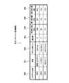
図2はキャッシュ管理情報1012の内容を示す説明図である。キャッシュ管理情報1012は、プログラム名称500、用途501、マウントポイント502、優先度503、推奨割当量504、最小割当量505および最大割当量506を含んで構成されている。なお、明細書において、推奨割当量504、最小割当量505および最大割当量506を併せてメモリ許容量という。
プログラム名称500は、実行するアプリケーションを特定するために用いられ、例えば「APP1」などの名称が示される。用途501は、アプリケーションの用途をあらわし、例えば、深夜バックアップなどの用途が示される。FIG. 2 is an explanatory diagram showing the contents of the
The
マウントポイント502は、ディスクキャッシュの対象となるデバイスやネットワークファイルシステム等をマウントするマウントポイントを指定するために用いる。マウントポイント数は1つでも複数でもよい。例えば、アプリケーションごとに複数のマウントポイントを指定することも可能である。
優先度503は、サーバ計算機10上における各アプリケーションの重要性を表わすもので、アプリケーションに対しディスクキャッシュを割り当てる際の優先度を示す。ここでは、優先度の最も低い「1」から、優先度の最も高い「10」までの10段階の優先度を準備している。The
The
推奨割当量504は、対応するアプリケーションが十分な性能を発揮するために必要なキャッシュ割り当てサイズを表わす。最小割当量505は、利用者の要求するアプリケーション性能を満たすために必要な最低限のキャッシュ割り当てサイズを表わす。
最大割当量506は、アプリケーションに割り当て可能なキャッシュサイズの上限値を表わす。The recommended
The
次に、前記したアプリケーション1013〜1015についてのキャッシュ割当量の計算処理を図3に基づいて説明する。
図3はサーバ計算機10におけるキャッシュ割当量の計算処理の流れを示す図である。
まず、サーバ計算機10のCPU102は、例えば、あるアプリケーション1015が導入されたタイミングで、オペレーティングシステム1010やアプリケーション1013〜1015に割当てられていない空きメモリ領域1016(図1参照)の空きメモリ量を計算する(S100)。Next, the cache allocation amount calculation processing for the
FIG. 3 is a diagram showing the flow of the cache allocation amount calculation process in the
First, the
続いて、CPU102は、各アプリケーション1013〜1015に対応する最小割当量505に指定された最小割当量をキャッシュ管理情報1012(図2参照)から読み出し、それらを合算した最小割当量の合計値が空きメモリ量を超えるかどうかを判定する(S101)。なお、図2では各アプリケーション1013〜1015の最小割当量は、それぞれ20MB、10MB、10MBであるので、これらを合算した40MBが最小割当量の合計値となる。
そして、空きメモリ量を超えると判定された場合(S101のYes)、CPU102は、必要なキャッシュ割当量が確保されないため、エラー処理として、管理用端末30にその旨の情報を送信する(S102)。
これに対して、空きメモリ量を超えないと判定された場合(S101のNo)、CPU102は、各アプリケーション1013〜1015の最小割当量をキャッシュ割当量として割り当てる(S103)。つまり、各最小割当量がキャッシュ割当量として確保される。Subsequently, the
If it is determined that the amount of free memory is exceeded (Yes in S101), the
On the other hand, when it is determined that the free memory amount is not exceeded (No in S101), the
次に、CPU102は、各アプリケーション1013〜1015に対応する推奨割当量504に指定された各推奨割当量をキャッシュ管理情報1012(図2参照)から読み出し、それらを合算した推奨割当量の合計値が空きメモリ量を超えるかどうかを判定する(S104)。そして、空きメモリ量を超えると判定された場合(S104のYes)、CPU102は、各アプリケーション1013〜1015に対応する各優先度503(図2参照)に指定された優先度順に、空きメモリ量を各アプリケーション1013〜1015の推奨割当量に応じて配分する(S106)。 Next, the
例えば、図2では各アプリケーション1013〜1015について、推奨割当量はそれぞれ180MB、60MB、70MBで、優先度はそれぞれ3、4、4であるので、これらの優先度順の比率で配分される。
具体的には、まず、優先度が「4」の2つのアプリケーション1014、1015の配分が、優先度「3」のアプリケーション1013に優先して行われる。つまり、アプリケーション1014には(空きメモリ量)×60MB/(180MB+60MB+70MB)により算出されたメモリ量が配分され、また、アプリケーション1015には(空きメモリ量)×70MB/(180MB+60MB+70MB)により算出されたメモリ量が配分される。
次に、優先度が「3」のアプリケーション1013の配分が行われる。つまり、アプリケーション1013には(空きメモリ量)−(各アプリケーション1014、1015に配分された総メモリ量)により得られたメモリ量が配分される。このようにすることにより、優先度の高いアプリケーションから順次、使用可能なメモリ量を推奨割当量の比率に応じて確保することが可能となる。For example, in FIG. 2, for each of the
Specifically, first, the distribution of the two
Next, the
これに対して、S104において、空きメモリ量を超えないと判断された場合(S104のNo)、CPU102は、各アプリケーション1013〜1015の推奨割当量を割り当てる(S106)。つまり、各推奨割当量がキャッシュ割当量として確保される。 On the other hand, when it is determined in S104 that the amount of free memory is not exceeded (No in S104), the
次に、CPU102は、各アプリケーション1013〜1015に対応する最大割当量506に指定された各最大割当量をキャッシュ管理情報1012(図2参照)から読み出し、それらを合算した最大割当量の合計値が空きメモリ量を超えるかどうかを判定する(S107)。そして、空きメモリ量を超えると判定された場合(S107のYes)、CPU102は、各アプリケーション1013〜1015に対応する各優先度503(図2参照)に指定された優先度順に、空きメモリ量を各アプリケーション1013〜1015の最大割当量に応じて配分する(S108)。 Next, the
例えば、図2では各アプリケーション1013〜1015について、最大割当量はそれぞれ300MB、150MB、100MBで、優先度はそれぞれ3、4、4であるので、これらの優先度順の比率で配分される。
具体的には、まず、優先度が「4」の2つのアプリケーション1014、1015の配分が、優先度「3」のアプリケーション1013に優先して行われる。つまり、アプリケーション1014には(空きメモリ量)×150MB/(300MB+150MB+100MB)により算出されたメモリ量が配分され、また、アプリケーション1015には(空きメモリ量)×100MB/(300MB+150MB+100MB)により算出されたメモリ量が配分される。
次に、優先度が「3」のアプリケーション1013の配分が行われる。つまり、アプリケーション1013には(空きメモリ量)−(各アプリケーション1014、1015に配分された総メモリ量)により得られたメモリ量が配分される。このようにすることにより、優先度の高いアプリケーションから順次、使用可能なメモリ量を最大割当量の比率に応じて確保することが可能となる。For example, in FIG. 2, the maximum allocation amounts are 300 MB, 150 MB, and 100 MB, and the priorities are 3, 4, and 4 for each of the
Specifically, first, the distribution of the two
Next, the
これに対して、S107において、空きメモリ量を超えないと判定された場合(S107のNo)、CPU102は、各アプリケーション1013〜1015の最大割当量を空きメモリ量に割り当てる(S109)。これにより、各アプリケーション1013〜1015の最大割当量分がキャッシュとして確保される。 On the other hand, when it is determined in S107 that the free memory amount is not exceeded (No in S107), the
次に、サーバ計算機10が、アプリケーション1013〜1015のキャッシュ割当量(以下これを「設定割当量」ともいう)を空きメモリ領域1016に設定した後、例えば、アプリケーション1013の実行中にディスクアクセスが発生し、それに伴いオペレーティングシステム1010およびキャッシュ管理プログラム1011がディスクキャッシュ割当て要求に応じてキャッシュ割当て処理を実行する場合について説明する。 Next, after the
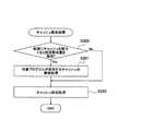
図4はサーバ計算機10におけるキャッシュ割当処理の流れを示す図である。
まず、サーバ計算機10のCPU102は、新規なキャッシュを空きメモリ領域1016に割り当てる際、新規にキャッシュを割当てると設定割当量を超過するかどうかを判定する(S200)。設定割当量は、例えば、ディスクアクセスが発生したアプリケーション1013に対応するものであり、メモリ101の所定領域から読み出される。つまり、S200では、CPU102は、アプリケーション1013の設定割当量と、アプリケーション1013に使用されるメモリ総使用量(割当て後のもの)とを比較し、メモリ総使用量が設定割当量の範囲内に収まるかどうかを判定する。FIG. 4 is a diagram showing the flow of cache allocation processing in the
First, when allocating a new cache to the
判定の結果、超過する場合(S200のYes)には、CPU102は、対象プログラムであるアプリケーション1013がすでに使用するキャッシュの解放処理を行う(S201)。解放処理としては、例えば、アクセス頻度の低い情報(例えばファイルなど)をキャッシュから解放する処理などがある。 As a result of the determination, if it exceeds (Yes in S200), the
その後、CPU102は、S201で解放処理したキャッシュに新規なキャッシュの割当処理を行う(S202)。これにより、アプリケーション単位でキャッシュの解放および割当てを行うことが可能となる。したがって、特定のアプリケーションのディスクアクセスに伴うキャッシュ割当量が過剰に増大することを抑止することが可能となる。よって、サーバ計算機10のシステム全体の処理能力の低下を防ぐことが可能となる。 Thereafter, the
以上説明したように、本実施の形態によれば、ディスクへの入出力処理を行う際にメモリ101上に入出力内容をキャッシュするサーバ計算機10において、そのサーバ計算機10上で動作するアプリケーションごとにキャッシュに割当てるメモリ量を制限する。そして、そのアプリケーションのキャッシュ使用量が、すでに設定されているメモリ量を超えそうになった場合に、他のアプリケーションが使用するキャッシュに影響を与えずに、当該アプリケーションが使用済みのキャッシュを解放して空きメモリを確保する。この結果、サーバ計算機10のディスクアクセス性能を維持することが可能となる。 As described above, according to the present embodiment, in the
図5は実施の形態2に係る計算機システムの構成例を示すブロック図である。なお、実施の形態1と同一部分については、同一の符号を付し重複説明を適宜省略する。
実施の形態2における計算機システムは、複数のサーバ計算機10、60を備えており、これらのサーバ計算機10、60が、ネットワーク80を介して接続されている。例えば、NAS(Network Attached Storage)として計算機システムを構成するようにしてもよい。サーバ計算機10は、ネットワークインタフェース103を備えた点が図1の場合と異なる。なお、図5では、2台のサーバ計算機が示されているが、3台以上のサーバ計算機をネットワーク80に接続して計算機システムを構成するようにしてもよい。FIG. 5 is a block diagram illustrating a configuration example of a computer system according to the second embodiment. In addition, about the same part as Embodiment 1, the same code | symbol is attached | subjected and duplication description is abbreviate | omitted suitably.
The computer system according to the second embodiment includes a plurality of
サーバ計算機60も、サーバ計算機10の構成と同様、メモリ601、CPU602およびネットワークインタフェース603を備えている。メモリ601には、OS(Operating System)6010と、キャッシュ管理プログラム6011と、キャッシュ管理情報6012と、アプリケーション6013、6014、6015(「APP4」、「APP5」、「APP6」に相当)とを格納している。そして、メモリ101には、空きメモリ領域6016が存在している。このように構成することにより、サーバ計算機60も、サーバ計算機10と同様、ハードディスク70から、OS6010、キャッシュ管理プログラム6011、キャッシュ管理情報6012および各種アプリケーション6013〜6015を読み込んで実行する。キャッシュ管理情報6012は、各アプリケーション6013〜6015毎に、プログラム名称500、用途501、マウントポイント502、優先度503、推奨割当量504、最小割当量505および最大割当量506を関連付けている(図2に相当)。その他の構成は、実施の形態1の場合と同様である。
このように構成することにより、サーバ計算機60も、アプリケーション6013〜6015のキャッシュ割当量を空きメモリ領域6016に決定して(図3の処理に相当)、各アプリケーション6013〜6015毎に所定分のキャッシュ割当量6020〜6022が割り当てられる。そして、サーバ計算機60も、各アプリケーション6013〜6015のディスクキャッシュ割当て要求に応じてキャッシュ割当て処理を実行している(図4の処理に相当)。Similarly to the configuration of the
With this configuration, the
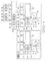
本実施の形態では、これらのサーバ計算機10、60は、ネットワーク80を通じて互いの動作状態を監視するように構成されている。そして、いずれか一方のサーバ計算機に障害(ハードウェア障害など)が発生し、そのサーバ計算機がアプリケーションを実行できなくなったとき、他のサーバ計算機がそのアプリケーションを引き継いで処理を継続する。このときのキャッシュ割当量の変化を図6に基づいて説明する。 In the present embodiment, these
図6は障害発生時のキャッシュ割当量の変化例を示す説明図である。図6では、サーバ計算機10にCPU102などの障害が発生したため、サーバ計算機60が、アプリケーション1013〜1015を引き継いで処理する場合が示されている。このため、サーバ計算機60では、引継ぎ前に動作していたアプリケーション6013〜6015、および引き継いだアプリケーション1013〜1015についてのキャッシュ割当量1020〜1022、6020〜6022が、空きメモリ領域6016に割り当てられている(図6の右上段参照)。これは次のような理由に基づく。すなわち、サーバ計算機60が、サーバ計算機10で動作していたアプリケーション1013〜1015をメモリ601に格納したため、空きメモリ領域6016が引継ぎ前に比べて縮小し(図6の右上下段参照)、縮小後の空きメモリ領域6016の空きメモリ量をもとに、個々のアプリケーション1013〜1015、6013〜6015についてのキャッシュ割当量を再割当てしたからである。 FIG. 6 is an explanatory diagram showing an example of a change in the cache allocation amount when a failure occurs. FIG. 6 shows a case where the
この再割当てを含む引継ぎ処理を図7に基づいて説明する。図7はサーバ計算機60の引継ぎ処理の流れを示す図である。ここでは、障害が発生したサーバ計算機10が、キャッシュ管理情報1012およびアプリケーション1013〜1015をメモリ101から読み出して、サーバ計算機60にネットワーク80を介して送信した場合を前提に説明することとする。
S300では、サーバ計算機60のCPU602は、すべてのアプリケーション1013〜1015、6013〜6015についてのキャッシュ割当量の計算処理を行う。このキャッシュ割当量の計算処理は、図3の処理と同様であるので、詳細説明を省略する。これにより、すべてのアプリケーション1013〜1015、6013〜6015についてのキャッシュ割当量が決定する。The takeover process including this reassignment will be described with reference to FIG. FIG. 7 is a diagram showing the flow of takeover processing of the
In S300, the
S301では、CPU602は、引継ぎ前から動作していたあるプログラム(例えばアプリケーションAPP4)についてのキャッシュ使用量(引継ぎ前にそのプログラムがすでに使用していたキャッシュ使用量)が、S300で計算したキャッシュ割当量を超過するかどうかを判定する。
判定の結果、超過しない場合(S301のNo)には、後記するS303に進み、他方、超過する場合(S301のYes)には、CPU602は、超過分のキャッシュを開放する(S302)。例えば、アクセス頻度の低い情報(例えばファイルなど)が開放される。In S301, the
As a result of the determination, if it does not exceed (No in S301), the process proceeds to S303 described later. On the other hand, if it exceeds (Yes in S301), the
S303では、CPU602は、引継ぎ前から動作していたすべてのプログラム(例えばアプリケーションAPP5、APP6)についての処理(S301、S302)を行ったかどうかを判断し(S303)、すべてのプログラムについてS301およびS302の処理を行うまで繰り返す。これにより、あるサーバ計算機10から他のサーバ計算機60への引継ぎ時においても、引き継いだアプリケーションに十分なディスクキャッシュが割当てられることとなる。したがって、サーバ計算機の処理性能が大きく悪化するといった事態を回避させることが可能となる。 In S303, the
その後、サーバ計算機10の障害が復旧し、アプリケーション1013〜1015がサーバ計算機10で実行可能な状態に戻った場合、管理者が、例えば手動操作により、アプリケーション1013〜1015をサーバ計算機10に再度切り替えて実行させる。この場合、サーバ計算機10は、キャッシュ管理プログラム1011に従って、各アプリケーション1013〜1015のキャッシュ割当量を引継ぎ前の状態に戻す。すなわち、サーバ計算機10が、図3に示したキャッシュ割当量の計算処理を実行することにより、キャッシュ割当量を再設定する。そして、サーバ計算機10は、アプリケーション1013〜1015の処理を再開する。このようにすることにより、計算機システムの障害時においても、最低限のディスクアクセス性能を維持することが可能となる。 After that, when the failure of the
なお、本発明は、前記した実施の形態1、2に限定されない。サーバ計算機のハードウェア構成、データ構造および処理の流れは、本発明の趣旨を逸脱しない限り、変更して構成するようにしてもよい。 The present invention is not limited to the first and second embodiments. The hardware configuration, data structure, and processing flow of the server computer may be changed and configured without departing from the spirit of the present invention.
10 サーバ計算機
20 ハードディスク
101 メモリ
102 CPU10
Claims (16)
Translated fromJapanese前記計算機は、メモリと処理部とを含んで構成され、前記メモリは、前記各プログラム毎に、当該プログラムがディスクキャッシュとして確保する前記メモリのメモリ許容量を記憶し、
前記処理部は、前記プログラムの実行に従ってディスクドライブへアクセスする際に、新規なディスクキャッシュを前記メモリに割り当てる場合、当該プログラムに対応するメモリ許容量を前記メモリから読み出し、読み出したメモリ許容量の範囲内に収まるように、前記ディスクキャッシュを前記メモリに割り当てることを特徴とするキャッシュ割当制御方法。A cache allocation control method used for a computer that executes a plurality of programs on a single OS,
The computer is configured to include a memory and a processing unit, and the memory stores, for each program, a memory allowable amount of the memory secured by the program as a disk cache,
When assigning a new disk cache to the memory when accessing the disk drive according to the execution of the program, the processing unit reads the memory capacity corresponding to the program from the memory, and the range of the memory capacity that has been read A cache allocation control method, comprising: allocating the disk cache to the memory so as to be contained within the memory.
障害が発生した前記計算機上で実行していた前記プログラムを他の前記計算機が前記ネットワークを通じて引き継ぐ場合、
他の前記計算機は、
前記引き継いだプログラムを含む少なくとも2以上の実行プログラムの各々について、各実行プログラム毎のメモリ許容量を記憶部から読み出し、それらの比率に応じて、前記メモリにディスクキャッシュを割り当てることを特徴とするキャッシュ割当制御方法。A cache allocation control method used in a computer system configured by connecting a plurality of computers that execute a plurality of programs on a single OS via a network,
When another computer takes over the program that was running on the failed computer through the network,
The other calculators are:
For each of at least two or more execution programs including the inherited program, a memory capacity for each execution program is read from the storage unit, and a disk cache is allocated to the memory according to a ratio thereof. Assignment control method.
前記処理部は、さらに、
前記メモリの空きメモリ量を計算し、
前記各プログラムの推奨割当量を前記メモリから読み出して、それら推奨割当量の合計値が前記計算した空きメモリ量を超えるかどうかを判定し、
判定の結果、前記空きメモリ量を超えない場合、前記各プログラムの推奨割当量を当該各プログラムの前記メモリ許容量として割り当てることを特徴とする請求項1に記載のキャッシュ割当制御方法。The memory further stores a recommended allocation amount of the disk cache for each program,
The processing unit further includes:
Calculate the amount of free memory in the memory,
Read the recommended allocation amount of each program from the memory, determine whether the total value of the recommended allocation amount exceeds the calculated free memory amount,
2. The cache allocation control method according to claim 1, wherein, as a result of the determination, if the amount of free memory is not exceeded, the recommended allocation amount of each program is allocated as the memory allowable amount of each program.
前記処理部は、さらに、
前記メモリの空きメモリ量を計算し、
前記各プログラムの最大割当量を前記メモリから読み出して、それら最大割当量の合計値が前記計算した空きメモリ量を超えるかどうかを判定し、
判定の結果、前記空きメモリ量を超えない場合、前記各プログラムの最大割当量を当該各プログラムの前記メモリ許容量として割り当てることを特徴とする請求項1に記載のキャッシュ割当制御方法。The memory further stores a maximum allocation amount of the disk cache for each program,
The processing unit further includes:
Calculate the amount of free memory in the memory,
Read the maximum allocated amount of each program from the memory, determine whether the total value of the maximum allocated amount exceeds the calculated free memory amount,
2. The cache allocation control method according to claim 1, wherein, as a result of the determination, if the free memory amount is not exceeded, the maximum allocation amount of each program is allocated as the memory allowable amount of each program.
前記処理部は、
前記判定の結果、前記空きメモリを超える場合、前記メモリに格納された前記優先度が高いプログラムから順次、そのプログラムの前記メモリ許容量を優先的に割り当てることを特徴とする請求項6または請求項7に記載のキャッシュ割当制御方法。The memory further stores, for each program, a priority indicating the importance of the program,
The processor is
7. As a result of the determination, when the free memory is exceeded, the memory allowable amount of the program is preferentially allocated in order from the program with the higher priority stored in the memory. 8. The cache allocation control method according to 7.
前記計算機の各々は、単一のOS上で複数のプログラムを実行するとともに、メモリと処理部とを含んで構成され、
前記メモリは、前記各プログラム毎に、当該プログラムがディスクキャッシュとして確保する前記メモリのメモリ許容量を記憶し、
前記計算機の処理部は、
前記各プログラムの実行に従ってディスクドライブへアクセスする際に、新規なディスクキャッシュを前記メモリに割り当てる場合、当該プログラムに対応するメモリ許容量を前記メモリから読み出し、読み出したメモリ許容量の範囲内に収まるように、前記ディスクキャッシュを前記メモリに割り当てることを特徴とする計算機システム。A computer system comprising a plurality of computers connected to a network,
Each of the computers executes a plurality of programs on a single OS and includes a memory and a processing unit.
The memory stores, for each program, a memory allowable amount of the memory that the program secures as a disk cache,
The processing unit of the computer is
When a new disk cache is allocated to the memory when accessing the disk drive according to the execution of each program, the memory capacity corresponding to the program is read from the memory so that it falls within the range of the read memory capacity. And assigning the disk cache to the memory.
障害が発生した前記計算機上で実行していた前記プログラムを他の前記計算機が前記ネットワークを通じて引き継ぐ場合、
前記他の計算機のメモリは、前記各プログラム毎に、前記ディスクキャッシュのメモリ許容量をさらに格納するとともに、
前記他の計算機の処理部は、
前記引き継いだプログラムを含む少なくとも2以上のプログラムの各々について、当該プログラムのメモリ許容量を前記メモリから読み出し、それらの比率に応じて、当該他の計算機のメモリに前記ディスクキャッシュを割り当てることを特徴とする計算機システム。The computer system according to claim 9, wherein
When another computer takes over the program that was running on the failed computer through the network,
The memory of the other computer further stores the memory capacity of the disk cache for each program,
The processing unit of the other computer is
For each of at least two programs including the inherited program, the memory capacity of the program is read from the memory, and the disk cache is allocated to the memory of the other computer in accordance with the ratio thereof. Computer system to do.
前記計算機の障害が復旧した場合、
当該復旧した計算機のメモリは、前記引き継ぎ前の各プログラムの前記メモリ許容量をさらに格納しているとともに、
前記復旧した計算機の処理部は、
前記引き継ぎ前の各プログラムの前記メモリ許容量を前記メモリから読み出し、それらのメモリ許容量に基づいて、当該復旧した計算機のメモリに前記ディスクキャッシュを再割り当てすることを特徴とする計算機システム。The computer system according to claim 11, wherein
If the computer failure is recovered,
The restored computer memory further stores the memory capacity of each program before the takeover,
The processing unit of the restored computer is
A computer system, wherein the memory capacity of each program before the takeover is read from the memory, and the disk cache is reassigned to the memory of the restored computer based on the memory capacity.
前記計算機の処理部は、さらに、
前記メモリの空きメモリ量を計算し、
前記各プログラムの推奨割当量を前記メモリから読み出して、それら推奨割当量の合計値が前記計算した空きメモリ量を超えるかどうかを判定し、
判定の結果、前記空きメモリ量を超えない場合、前記各プログラムの前記推奨割当量を当該各プログラムの前記メモリ許容量として割り当てることを特徴とする請求項9に記載の計算機システム。The memory of the computer further stores a recommended allocation amount of the disk cache for each program,
The processing unit of the computer further includes:
Calculate the amount of free memory in the memory,
Read the recommended allocation amount of each program from the memory, determine whether the total value of the recommended allocation amount exceeds the calculated free memory amount,
10. The computer system according to claim 9, wherein, as a result of the determination, if the free memory amount is not exceeded, the recommended allocation amount of each program is allocated as the memory allowable amount of each program.
前記計算機の処理部は、さらに、
前記プログラム毎の最大割当量を前記メモリから読み出して、それら最大割当量の合計値が前記計算した空きメモリ量を超えるかどうかを判定し、
判定の結果、前記空きメモリ量を超えない場合、前記各プログラムの前記最大割当量を各プログラムの前記メモリ許容量として割り当てることを特徴とする請求項9に記載の計算機システム。The memory of the computer further stores a maximum allocation amount of the disk cache for each program,
The processing unit of the computer further includes:
Read the maximum allocation amount for each program from the memory, determine whether the total value of the maximum allocation amount exceeds the calculated free memory amount,
10. The computer system according to claim 9, wherein, as a result of the determination, if the amount of free memory is not exceeded, the maximum allocation amount of each program is allocated as the memory allowable amount of each program.
前記計算機の処理部は、
前記判定の結果、前記空きメモリを超える場合、前記メモリに格納された前記優先度が高いプログラムから順次、そのプログラムの前記メモリ許容量を優先的に割り当てることを特徴とする請求項14または請求項15に記載の計算機システム。The memory of the computer further stores a priority indicating the importance of the program for each program,
The processing unit of the computer is
15. As a result of the determination, when the free memory is exceeded, the memory capacity of the program is preferentially assigned in order from the program with the higher priority stored in the memory. 15. The computer system according to 15.
Priority Applications (2)
| Application Number | Priority Date | Filing Date | Title |
|---|---|---|---|
| JP2005177540AJP2006350780A (en) | 2005-06-17 | 2005-06-17 | Cache allocation control method |
| US11/245,173US20060288159A1 (en) | 2005-06-17 | 2005-10-07 | Method of controlling cache allocation |
Applications Claiming Priority (1)
| Application Number | Priority Date | Filing Date | Title |
|---|---|---|---|
| JP2005177540AJP2006350780A (en) | 2005-06-17 | 2005-06-17 | Cache allocation control method |
Publications (1)
| Publication Number | Publication Date |
|---|---|
| JP2006350780Atrue JP2006350780A (en) | 2006-12-28 |
Family
ID=37574712
Family Applications (1)
| Application Number | Title | Priority Date | Filing Date |
|---|---|---|---|
| JP2005177540APendingJP2006350780A (en) | 2005-06-17 | 2005-06-17 | Cache allocation control method |
Country Status (2)
| Country | Link |
|---|---|
| US (1) | US20060288159A1 (en) |
| JP (1) | JP2006350780A (en) |
Cited By (7)
| Publication number | Priority date | Publication date | Assignee | Title |
|---|---|---|---|---|
| JP2010097526A (en)* | 2008-10-20 | 2010-04-30 | Hitachi Ltd | Cache configuration management system, management server and cache configuration management method |
| JP2010286923A (en)* | 2009-06-09 | 2010-12-24 | Hitachi Ltd | Cache control apparatus and method |
| US8239634B2 (en) | 2007-06-05 | 2012-08-07 | Nec Corporation | Input/output control based on information specifying input/output issuing source and input/output priority |
| JP2013196481A (en)* | 2012-03-21 | 2013-09-30 | Nec Corp | Cache device, information processing system, and cache method |
| US8918613B2 (en) | 2011-02-02 | 2014-12-23 | Hitachi, Ltd. | Storage apparatus and data management method for storage area allocation based on access frequency |
| WO2015045046A1 (en)* | 2013-09-26 | 2015-04-02 | 株式会社日立製作所 | Computer system and memory allocation adjustment method for computer system |
| JP2016181030A (en)* | 2015-03-23 | 2016-10-13 | 富士通株式会社 | Information processing apparatus, storage device control method, storage device control program, and information processing system |
Families Citing this family (15)
| Publication number | Priority date | Publication date | Assignee | Title |
|---|---|---|---|---|
| JP2005339299A (en)* | 2004-05-28 | 2005-12-08 | Hitachi Ltd | Cache control method for storage device |
| US8862813B2 (en) | 2005-12-29 | 2014-10-14 | Datacore Software Corporation | Method, computer program product and appartus for accelerating responses to requests for transactions involving data operations |
| US7752386B1 (en)* | 2005-12-29 | 2010-07-06 | Datacore Software Corporation | Application performance acceleration |
| US7640262B1 (en)* | 2006-06-30 | 2009-12-29 | Emc Corporation | Positional allocation |
| US7930559B1 (en)* | 2006-06-30 | 2011-04-19 | Emc Corporation | Decoupled data stream and access structures |
| US8239640B2 (en)* | 2008-10-09 | 2012-08-07 | Dataram, Inc. | System for controlling performance aspects of a data storage and access routine |
| US8320392B1 (en)* | 2009-12-16 | 2012-11-27 | Integrated Device Technology, Inc. | Method and apparatus for programmable buffer with dynamic allocation to optimize system throughput with deadlock avoidance on switches |
| US8631198B2 (en)* | 2010-08-06 | 2014-01-14 | Seagate Technology Llc | Dynamic cache reduction utilizing voltage warning mechanism |
| US9210049B2 (en)* | 2011-11-22 | 2015-12-08 | Adc Telecommunications, Inc. | Intelligent infrastructure management user device |
| US9335948B1 (en)* | 2012-03-27 | 2016-05-10 | Emc Corporation | Method and apparatus for enabling access to tiered shared storage using dynamic tier partitioning |
| US10198192B2 (en)* | 2015-03-31 | 2019-02-05 | Veritas Technologies Llc | Systems and methods for improving quality of service within hybrid storage systems |
| CN106095587B (en)* | 2016-06-24 | 2019-12-24 | 北京金山安全软件有限公司 | Cache scanning method and device of application program and electronic equipment |
| US10635594B1 (en)* | 2016-12-30 | 2020-04-28 | EMC IP Holding Company LLC | Dynamically redistribute cache space based on time savings |
| US10592420B1 (en)* | 2016-12-30 | 2020-03-17 | EMC IP Holding Company LLC | Dynamically redistribute cache space with min-max technique |
| CN111984197B (en)* | 2020-08-24 | 2023-12-15 | 许昌学院 | Computer Cache Allocation Method |
Family Cites Families (5)
| Publication number | Priority date | Publication date | Assignee | Title |
|---|---|---|---|---|
| US5996019A (en)* | 1995-07-19 | 1999-11-30 | Fujitsu Network Communications, Inc. | Network link access scheduling using a plurality of prioritized lists containing queue identifiers |
| US6075938A (en)* | 1997-06-10 | 2000-06-13 | The Board Of Trustees Of The Leland Stanford Junior University | Virtual machine monitors for scalable multiprocessors |
| US6941437B2 (en)* | 2001-07-19 | 2005-09-06 | Wind River Systems, Inc. | Memory allocation scheme |
| US7213246B1 (en)* | 2002-03-28 | 2007-05-01 | Veritas Operating Corporation | Failing over a virtual machine |
| US7299468B2 (en)* | 2003-04-29 | 2007-11-20 | International Business Machines Corporation | Management of virtual machines to utilize shared resources |
- 2005
- 2005-06-17JPJP2005177540Apatent/JP2006350780A/enactivePending
- 2005-10-07USUS11/245,173patent/US20060288159A1/ennot_activeAbandoned
Cited By (9)
| Publication number | Priority date | Publication date | Assignee | Title |
|---|---|---|---|---|
| US8239634B2 (en) | 2007-06-05 | 2012-08-07 | Nec Corporation | Input/output control based on information specifying input/output issuing source and input/output priority |
| JP2010097526A (en)* | 2008-10-20 | 2010-04-30 | Hitachi Ltd | Cache configuration management system, management server and cache configuration management method |
| JP2010286923A (en)* | 2009-06-09 | 2010-12-24 | Hitachi Ltd | Cache control apparatus and method |
| US8285935B2 (en) | 2009-06-09 | 2012-10-09 | Hitachi, Ltd. | Cache control apparatus and method |
| US8918613B2 (en) | 2011-02-02 | 2014-12-23 | Hitachi, Ltd. | Storage apparatus and data management method for storage area allocation based on access frequency |
| JP2013196481A (en)* | 2012-03-21 | 2013-09-30 | Nec Corp | Cache device, information processing system, and cache method |
| WO2015045046A1 (en)* | 2013-09-26 | 2015-04-02 | 株式会社日立製作所 | Computer system and memory allocation adjustment method for computer system |
| US9632931B2 (en) | 2013-09-26 | 2017-04-25 | Hitachi, Ltd. | Computer system and memory allocation adjustment method for computer system |
| JP2016181030A (en)* | 2015-03-23 | 2016-10-13 | 富士通株式会社 | Information processing apparatus, storage device control method, storage device control program, and information processing system |
Also Published As
| Publication number | Publication date |
|---|---|
| US20060288159A1 (en) | 2006-12-21 |
Similar Documents
| Publication | Publication Date | Title |
|---|---|---|
| JP2006350780A (en) | Cache allocation control method | |
| US10387202B2 (en) | Quality of service implementation in a networked storage system with hierarchical schedulers | |
| US9396026B2 (en) | Allocating a task to a computer based on determined resources | |
| JP4519098B2 (en) | Computer management method, computer system, and management program | |
| WO2012147116A1 (en) | Computer system and virtual machine control method | |
| US11822445B2 (en) | Methods and systems for rapid failure recovery for a distributed storage system | |
| US12099412B2 (en) | Storage system spanning multiple failure domains | |
| US20240053886A1 (en) | File operations in a distributed storage system | |
| US7437727B2 (en) | Method and apparatus for runtime resource deadlock avoidance in a raid system | |
| US11899621B2 (en) | Access redirection in a distributive file system | |
| Wang et al. | Provision of storage QoS in distributed file systems for clouds | |
| CN112162818A (en) | Virtual memory allocation method and device, electronic equipment and storage medium | |
| US12164505B2 (en) | Two-phase commit using reserved log sequence values | |
| US20230185632A1 (en) | Management system, data rebalancing management method, and recording medium | |
| JP2010026828A (en) | Method for controlling virtual computer | |
| Brito et al. | IBM PowerVM Virtualization Active Memory Sharing | |
| US20250060991A1 (en) | Background maintenance task regulation and scheduling | |
| CN120029787A (en) | A method, system and device for creating a NUMA-level memory copy | |
| CN118467172A (en) | Host memory management method, device, storage medium and server |