JP2006347412A - Roller brake mounting adapter - Google Patents
Roller brake mounting adapterDownload PDFInfo
- Publication number
- JP2006347412A JP2006347412AJP2005177231AJP2005177231AJP2006347412AJP 2006347412 AJP2006347412 AJP 2006347412AJP 2005177231 AJP2005177231 AJP 2005177231AJP 2005177231 AJP2005177231 AJP 2005177231AJP 2006347412 AJP2006347412 AJP 2006347412A
- Authority
- JP
- Japan
- Prior art keywords
- hub
- brake
- contact surface
- roller brake
- roller
- Prior art date
- Legal status (The legal status is an assumption and is not a legal conclusion. Google has not performed a legal analysis and makes no representation as to the accuracy of the status listed.)
- Pending
Links
- 230000002093peripheral effectEffects0.000claimsabstractdescription25
- 230000005540biological transmissionEffects0.000description3
- 238000001816coolingMethods0.000description3
- 229910000838Al alloyInorganic materials0.000description1
- 238000005452bendingMethods0.000description1
- 239000004519greaseSubstances0.000description1
- 230000001788irregularEffects0.000description1
- 238000012423maintenanceMethods0.000description1
- 229910052751metalInorganic materials0.000description1
- 239000002184metalSubstances0.000description1
Images


Classifications
- F—MECHANICAL ENGINEERING; LIGHTING; HEATING; WEAPONS; BLASTING
- F16—ENGINEERING ELEMENTS AND UNITS; GENERAL MEASURES FOR PRODUCING AND MAINTAINING EFFECTIVE FUNCTIONING OF MACHINES OR INSTALLATIONS; THERMAL INSULATION IN GENERAL
- F16D—COUPLINGS FOR TRANSMITTING ROTATION; CLUTCHES; BRAKES
- F16D51/00—Brakes with outwardly-movable braking members co-operating with the inner surface of a drum or the like
- F16D51/10—Brakes with outwardly-movable braking members co-operating with the inner surface of a drum or the like shaped as exclusively radially-movable brake-shoes
- F16D51/12—Brakes with outwardly-movable braking members co-operating with the inner surface of a drum or the like shaped as exclusively radially-movable brake-shoes mechanically actuated
- B—PERFORMING OPERATIONS; TRANSPORTING
- B60—VEHICLES IN GENERAL
- B60L—PROPULSION OF ELECTRICALLY-PROPELLED VEHICLES; SUPPLYING ELECTRIC POWER FOR AUXILIARY EQUIPMENT OF ELECTRICALLY-PROPELLED VEHICLES; ELECTRODYNAMIC BRAKE SYSTEMS FOR VEHICLES IN GENERAL; MAGNETIC SUSPENSION OR LEVITATION FOR VEHICLES; MONITORING OPERATING VARIABLES OF ELECTRICALLY-PROPELLED VEHICLES; ELECTRIC SAFETY DEVICES FOR ELECTRICALLY-PROPELLED VEHICLES
- B60L50/00—Electric propulsion with power supplied within the vehicle
- B60L50/20—Electric propulsion with power supplied within the vehicle using propulsion power generated by humans or animals
- B—PERFORMING OPERATIONS; TRANSPORTING
- B60—VEHICLES IN GENERAL
- B60L—PROPULSION OF ELECTRICALLY-PROPELLED VEHICLES; SUPPLYING ELECTRIC POWER FOR AUXILIARY EQUIPMENT OF ELECTRICALLY-PROPELLED VEHICLES; ELECTRODYNAMIC BRAKE SYSTEMS FOR VEHICLES IN GENERAL; MAGNETIC SUSPENSION OR LEVITATION FOR VEHICLES; MONITORING OPERATING VARIABLES OF ELECTRICALLY-PROPELLED VEHICLES; ELECTRIC SAFETY DEVICES FOR ELECTRICALLY-PROPELLED VEHICLES
- B60L50/00—Electric propulsion with power supplied within the vehicle
- B60L50/50—Electric propulsion with power supplied within the vehicle using propulsion power supplied by batteries or fuel cells
- B60L50/60—Electric propulsion with power supplied within the vehicle using propulsion power supplied by batteries or fuel cells using power supplied by batteries
- B60L50/66—Arrangements of batteries
- B—PERFORMING OPERATIONS; TRANSPORTING
- B60—VEHICLES IN GENERAL
- B60L—PROPULSION OF ELECTRICALLY-PROPELLED VEHICLES; SUPPLYING ELECTRIC POWER FOR AUXILIARY EQUIPMENT OF ELECTRICALLY-PROPELLED VEHICLES; ELECTRODYNAMIC BRAKE SYSTEMS FOR VEHICLES IN GENERAL; MAGNETIC SUSPENSION OR LEVITATION FOR VEHICLES; MONITORING OPERATING VARIABLES OF ELECTRICALLY-PROPELLED VEHICLES; ELECTRIC SAFETY DEVICES FOR ELECTRICALLY-PROPELLED VEHICLES
- B60L2200/00—Type of vehicles
- B60L2200/12—Bikes
- B—PERFORMING OPERATIONS; TRANSPORTING
- B60—VEHICLES IN GENERAL
- B60L—PROPULSION OF ELECTRICALLY-PROPELLED VEHICLES; SUPPLYING ELECTRIC POWER FOR AUXILIARY EQUIPMENT OF ELECTRICALLY-PROPELLED VEHICLES; ELECTRODYNAMIC BRAKE SYSTEMS FOR VEHICLES IN GENERAL; MAGNETIC SUSPENSION OR LEVITATION FOR VEHICLES; MONITORING OPERATING VARIABLES OF ELECTRICALLY-PROPELLED VEHICLES; ELECTRIC SAFETY DEVICES FOR ELECTRICALLY-PROPELLED VEHICLES
- B60L2220/00—Electrical machine types; Structures or applications thereof
- B60L2220/40—Electrical machine applications
- B60L2220/44—Wheel Hub motors, i.e. integrated in the wheel hub
- B—PERFORMING OPERATIONS; TRANSPORTING
- B60—VEHICLES IN GENERAL
- B60L—PROPULSION OF ELECTRICALLY-PROPELLED VEHICLES; SUPPLYING ELECTRIC POWER FOR AUXILIARY EQUIPMENT OF ELECTRICALLY-PROPELLED VEHICLES; ELECTRODYNAMIC BRAKE SYSTEMS FOR VEHICLES IN GENERAL; MAGNETIC SUSPENSION OR LEVITATION FOR VEHICLES; MONITORING OPERATING VARIABLES OF ELECTRICALLY-PROPELLED VEHICLES; ELECTRIC SAFETY DEVICES FOR ELECTRICALLY-PROPELLED VEHICLES
- B60L2240/00—Control parameters of input or output; Target parameters
- B60L2240/10—Vehicle control parameters
- B60L2240/36—Temperature of vehicle components or parts
- B—PERFORMING OPERATIONS; TRANSPORTING
- B60—VEHICLES IN GENERAL
- B60L—PROPULSION OF ELECTRICALLY-PROPELLED VEHICLES; SUPPLYING ELECTRIC POWER FOR AUXILIARY EQUIPMENT OF ELECTRICALLY-PROPELLED VEHICLES; ELECTRODYNAMIC BRAKE SYSTEMS FOR VEHICLES IN GENERAL; MAGNETIC SUSPENSION OR LEVITATION FOR VEHICLES; MONITORING OPERATING VARIABLES OF ELECTRICALLY-PROPELLED VEHICLES; ELECTRIC SAFETY DEVICES FOR ELECTRICALLY-PROPELLED VEHICLES
- B60L2250/00—Driver interactions
- B60L2250/24—Driver interactions by lever actuation
- B—PERFORMING OPERATIONS; TRANSPORTING
- B60—VEHICLES IN GENERAL
- B60L—PROPULSION OF ELECTRICALLY-PROPELLED VEHICLES; SUPPLYING ELECTRIC POWER FOR AUXILIARY EQUIPMENT OF ELECTRICALLY-PROPELLED VEHICLES; ELECTRODYNAMIC BRAKE SYSTEMS FOR VEHICLES IN GENERAL; MAGNETIC SUSPENSION OR LEVITATION FOR VEHICLES; MONITORING OPERATING VARIABLES OF ELECTRICALLY-PROPELLED VEHICLES; ELECTRIC SAFETY DEVICES FOR ELECTRICALLY-PROPELLED VEHICLES
- B60L2250/00—Driver interactions
- B60L2250/26—Driver interactions by pedal actuation
- F—MECHANICAL ENGINEERING; LIGHTING; HEATING; WEAPONS; BLASTING
- F16—ENGINEERING ELEMENTS AND UNITS; GENERAL MEASURES FOR PRODUCING AND MAINTAINING EFFECTIVE FUNCTIONING OF MACHINES OR INSTALLATIONS; THERMAL INSULATION IN GENERAL
- F16D—COUPLINGS FOR TRANSMITTING ROTATION; CLUTCHES; BRAKES
- F16D2121/00—Type of actuator operation force
- F16D2121/14—Mechanical
- F—MECHANICAL ENGINEERING; LIGHTING; HEATING; WEAPONS; BLASTING
- F16—ENGINEERING ELEMENTS AND UNITS; GENERAL MEASURES FOR PRODUCING AND MAINTAINING EFFECTIVE FUNCTIONING OF MACHINES OR INSTALLATIONS; THERMAL INSULATION IN GENERAL
- F16D—COUPLINGS FOR TRANSMITTING ROTATION; CLUTCHES; BRAKES
- F16D2125/00—Components of actuators
- F16D2125/18—Mechanical mechanisms
- F16D2125/58—Mechanical mechanisms transmitting linear movement
- F16D2125/60—Cables or chains, e.g. Bowden cables
- Y—GENERAL TAGGING OF NEW TECHNOLOGICAL DEVELOPMENTS; GENERAL TAGGING OF CROSS-SECTIONAL TECHNOLOGIES SPANNING OVER SEVERAL SECTIONS OF THE IPC; TECHNICAL SUBJECTS COVERED BY FORMER USPC CROSS-REFERENCE ART COLLECTIONS [XRACs] AND DIGESTS
- Y02—TECHNOLOGIES OR APPLICATIONS FOR MITIGATION OR ADAPTATION AGAINST CLIMATE CHANGE
- Y02T—CLIMATE CHANGE MITIGATION TECHNOLOGIES RELATED TO TRANSPORTATION
- Y02T10/00—Road transport of goods or passengers
- Y02T10/60—Other road transportation technologies with climate change mitigation effect
- Y02T10/70—Energy storage systems for electromobility, e.g. batteries
Landscapes
- Engineering & Computer Science (AREA)
- Mechanical Engineering (AREA)
- Power Engineering (AREA)
- Transportation (AREA)
- General Engineering & Computer Science (AREA)
- Life Sciences & Earth Sciences (AREA)
- Sustainable Development (AREA)
- Sustainable Energy (AREA)
- Braking Arrangements (AREA)
Abstract
Description
Translated fromJapanese本発明は、ローラブレーキをハブに装着するためのアダプタ、特に、ローラブレーキを自転車用モータ内蔵ハブに装着するためのローラブレーキ取付アダプタに関する。 The present invention relates to an adapter for mounting a roller brake to a hub, and more particularly to a roller brake mounting adapter for mounting a roller brake to a bicycle motor built-in hub.
近年、モータ等を利用して、ペダルを漕ぐ力を補助する電動補助付自転車(電動アシスト自転車)等の普及、発展は、著しく、特に、中国国内では、車輪のハブにモータを内蔵し、車輪の回転を補助したり、または、車輪の回転自身をモータに行わせ、ペダルを漕がなくても、自転車が前進したりする電動自転車の普及、発展が著しい。 In recent years, the spread and development of electrically assisted bicycles (electrically assisted bicycles) that use a motor or the like to assist the pedaling force has been remarkable, especially in China, where the motor is built in the wheel hub, Electric bicycles that assist the rotation of the vehicle or that cause the motor to rotate the wheel itself and move the bicycle forward without the need for a pedal are remarkable.
しかしながら、これら電動自転車は、モータやその電源となる電池が必要になり、自転車自身が重くなり、また、モータの駆動、アシストを受けて走行するため、通常の自転車より、高速で走行可能であるので、走行中の慣性力が大きくなるにもかかわらず、これらの電動自転車には、通常の自転車と同じ、内拡ブレーキや、バンドブレーキや、カンチブレーキ等の一般的なブレーキが利用されており、その制動力不足が疑問視されている。 However, these electric bicycles require a motor and a battery as a power source thereof, the bicycle itself becomes heavy, and the motor is driven and assisted to run, so that it can run at a higher speed than a normal bicycle. So, even though the inertial force during driving increases, these electric bicycles use the same general brakes such as the internal brake, band brake, cantilever brake, etc. as normal bicycles. The lack of braking power has been questioned.
このような、電動自転車に搭載される従来のモータ内蔵ハブが知られている(たとえば、特許文献1参照)。従来のモータ内蔵ハブは、ハブ軸と、ハブ軸を保護するケーシングとを備えている。ケーシングは、ハブ軸に固定された固定側ケーシングと、ハブ軸を覆うハブシェル(回転ドラム)とを備えている。固定側ケーシングには、内拡ブレーキ装置のブレーキシューが設けられている。内拡ブレーキ装置のブレーキドラムは、ハブシェルの軸受支持部分から突出して形成された筒状部に固定されている。 A conventional motor built-in hub mounted on such an electric bicycle is known (see, for example, Patent Document 1). A conventional motor built-in hub includes a hub shaft and a casing that protects the hub shaft. The casing includes a stationary casing fixed to the hub shaft, and a hub shell (rotary drum) that covers the hub shaft. The stationary casing is provided with a brake shoe for the internal expansion brake device. The brake drum of the internal expansion brake device is fixed to a cylindrical portion that protrudes from the bearing support portion of the hub shell.
従来、制動力が高い自転車用ブレーキとして、ローラブレーキが知られている。ローラブレーキは、自転車のフレームに固定可能な固定ブラケットと、自転車のハブに回転不能に装着され内周面に制動面を有する円筒状のブレーキドラムと、固定ブラケットに対して回転不能であり、制動面に接触可能な接触面を有し、ブレーキドラムに制動作用する複数のブレーキシューと、ブレーキシューを径方向内方に付勢する付勢部材と、周方向に間隔を隔てて配置された複数のローラと、ブレーキシューを前記ブレーキドラムに圧接させるブレーキ動作部とを有している。ブレーキ動作部は、回動によりローラを径方向外方に押圧するカム機構と、を有している。 Conventionally, a roller brake is known as a bicycle brake having a high braking force. The roller brake is a fixed bracket that can be fixed to the bicycle frame, a cylindrical brake drum that is non-rotatably mounted on the bicycle hub and has a braking surface on the inner peripheral surface, and a non-rotatable brake with respect to the fixed bracket. A plurality of brake shoes that have a contact surface that can contact the surface and that act on the brake drum, a biasing member that biases the brake shoe radially inward, and a plurality that are spaced apart in the circumferential direction And a brake operating part that presses the brake shoe against the brake drum. The brake operation unit includes a cam mechanism that presses the roller radially outward by rotation.
このようなローラブレーキをハブに装着する場合、最初にブレーキドラムをハブに装着する。そして、固定ブラケットにセットされたブレーキシューと付勢部材とブレーキ動作部とをハブ軸に装着し、固定ブラケットを回り止めする。最後に固定ブラケットをナットによりハブ軸に固定する。
ローラブレーキは、ローラによりブレーキシューをブレーキドラムに均等に圧接することができるため、内拡ブレーキやバンドブレーキのようにブレーキドラムの一部にしか圧接しない一般のブレーキに比べて強いブレーキ力を得ることができる。このため、ブレーキドラムをハブに装着する部分の強度を一般のブレーキに比べて高くしなければならない。また、ローラブレーキは、一般のブレーキより軸方向の厚みが厚いため、その取付スペースを確保しなければならない。 The roller brake can press the brake shoe evenly against the brake drum by the roller, so it can obtain a stronger braking force than a general brake that presses against only a part of the brake drum, such as an internal brake or a band brake. be able to. For this reason, the strength of the portion where the brake drum is mounted on the hub must be higher than that of a general brake. In addition, since the roller brake is thicker in the axial direction than a general brake, a mounting space must be secured.
このようなローラブレーキをモータ内蔵ハブに装着する場合、その装着スペースがないだけでなく、そのままでは伝達トルクが充分ではなく、強度面も含めて取り付けできないという問題がある。 When such a roller brake is mounted on a hub with a built-in motor, there is a problem that not only the mounting space is not provided, but also the transmission torque is not sufficient as it is, and it cannot be mounted including the strength.
本発明の課題は、ローラブレーキをモータ内蔵ハブに取り付けできるアダプタを提供することにある。 The subject of this invention is providing the adapter which can attach a roller brake to a motor built-in hub.
発明1に係るローラブレーキ取付アダプタは、自転車用モータ内蔵ハブに装着可能なアダプタであって、ハブのハブシェルの側端部に装着されるフランジ部と、フランジ部に一体形成された筒状部とを備え、筒状部は、内周面に設けられ、ハブシェルをハブ軸に回転自在に支持する軸受と接触する第1接触面と、外周面に設けられ、周方向に間隔を隔てて形成された凹凸部を有し、ローラブレーキのブレーキドラムと接触する第2接触面と、を有することを特徴とする。 A roller brake mounting adapter according to a first aspect of the present invention is an adapter that can be attached to a bicycle motor built-in hub, a flange portion that is attached to a side end portion of the hub shell of the hub, and a cylindrical portion that is integrally formed with the flange portion. The cylindrical portion is provided on the inner peripheral surface, and is provided on the outer peripheral surface with a first contact surface that contacts a bearing that rotatably supports the hub shell on the hub shaft, and is formed at an interval in the circumferential direction. And a second contact surface that contacts the brake drum of the roller brake.
このアダプタをモータ内蔵ハブに装着する際には、フランジ部をハブのハブシェルの側端部に装着する。すると、第2接触面にローラブレーキのブレーキドラムを装着可能になる。また、第1接触面に軸受を装着できる。ここでは、フランジ部と筒状部とでアダプタを構成し、筒状部の第2接触面に伝達トルクが大きい凹凸部を設けたので、通常のバンドブレーキより強いブレーキ力を有するローラブレーキであっても簡単にモータ内蔵ハブに取り付けることができる。 When this adapter is attached to the motor-integrated hub, the flange portion is attached to the side end portion of the hub shell of the hub. Then, the brake drum of the roller brake can be mounted on the second contact surface. A bearing can be mounted on the first contact surface. Here, an adapter is constituted by the flange portion and the cylindrical portion, and an uneven portion having a large transmission torque is provided on the second contact surface of the cylindrical portion. Therefore, the roller brake has a stronger braking force than a normal band brake. But it can be easily attached to the hub with a built-in motor.
発明2に係るローラブレーキ取付アダプタは、発明1に記載のアダプタにおいて、フランジ部は、側端部に着脱可能に装着される。この場合には、アダプタを着脱できるので、も内蔵ハブ及びローラブレーキのメンテナンスが容易である。 A roller brake mounting adapter according to a second aspect is the adapter according to the first aspect, wherein the flange portion is detachably attached to the side end portion. In this case, since the adapter can be attached and detached, maintenance of the built-in hub and the roller brake is easy.
発明3に係るローラブレーキ取付アダプタは、発明2に記載のアダプタにおいて、フランジ部は、側端部の内側面に装着されることを特徴とする。この場合には、アダプタの装着部分がハブの内側に隠れるのでアダプタを設けてもハブの外形が変化せず、ローラブレーキを簡単に装着できる。 A roller brake mounting adapter according to a third aspect of the present invention is the adapter according to the second aspect, wherein the flange portion is attached to the inner side surface of the side end portion. In this case, since the mounting portion of the adapter is hidden inside the hub, the outer shape of the hub does not change even if the adapter is provided, and the roller brake can be easily mounted.
発明4に係るローラブレーキ取付アダプタは、発明2に記載のアダプタにおいて、第1接触面の少なくとも一部がハブシェルの側端部の外側面より内側に配置されていることを特徴とする。この場合には、軸受の少なくとも一部が外側面より内側に配置されるので、軸受に作用するラジアル方向の力を受けやすくなる。 A roller brake mounting adapter according to a fourth aspect is characterized in that, in the adapter according to the second aspect, at least a part of the first contact surface is disposed on the inner side of the outer surface of the side end portion of the hub shell. In this case, since at least a part of the bearing is disposed on the inner side of the outer surface, it is easy to receive a radial force acting on the bearing.
発明5に係るローラブレーキ取付アダプタは、発明3に記載のアダプタにおいて、第1接触面の少なくとも一部がハブシェルの側端部の外側面より内側に配置されていることを特徴とする、請求項3に記載のローラブレーキ取付アダプタ。この場合には、軸受の少なくとも一部が外側面より内側に配置されるので、軸受に作用するラジアル方向の力を受けやすくなるとともに、ローラブレーキを取り付けるためのスペースを確保することができる。 The roller brake mounting adapter according to a fifth aspect is characterized in that, in the adapter according to the third aspect, at least a part of the first contact surface is disposed on the inner side of the outer surface of the side end portion of the hub shell. 3. The roller brake mounting adapter according to 3. In this case, since at least a part of the bearing is disposed inside the outer surface, it is easy to receive a radial force acting on the bearing, and a space for attaching the roller brake can be secured.
発明6に係るローラブレーキ取付アダプタは、発明1から5のいずれかに記載のアダプタにおいて、第2接触面の少なくとも一部は第1接触面より外側に配置されている。この場合には、ローラブレーキが軸受支持面より外側に配置されるので、ローラブレーキを第2接触面に装着しやすくなるとともに、接触面をより広く確保できる。 A roller brake mounting adapter according to a sixth aspect of the invention is the adapter according to any one of the first to fifth aspects, wherein at least a part of the second contact surface is disposed outside the first contact surface. In this case, since the roller brake is disposed outside the bearing support surface, the roller brake can be easily mounted on the second contact surface, and a wider contact surface can be secured.
発明7に係るローラブレーキ取付アダプタは、発明1から5のいずれかに記載のアダプタにおいて、フランジ部は、ハブシェルの外側から挿入されたねじ部材によりハブシェルに固定可能であることを特徴とする。この場合には、外側からねじ部材を装着できるので、ねじ部材によりハブシェルを固定するのが容易である。 A roller brake mounting adapter according to a seventh aspect of the present invention is the adapter according to any one of the first to fifth aspects, wherein the flange portion can be fixed to the hub shell by a screw member inserted from the outside of the hub shell. In this case, since the screw member can be attached from the outside, it is easy to fix the hub shell by the screw member.
本発明によれば、フランジ部と筒状部とでアダプタを構成し、筒状部の第2接触面に伝達トルクが大きい凹凸部を設けたので、通常のバンドブレーキより強いブレーキ力を有するローラブレーキであっても簡単にモータ内蔵ハブに取り付けることができる。 According to the present invention, the flange portion and the cylindrical portion constitute an adapter, and the uneven portion having a large transmission torque is provided on the second contact surface of the cylindrical portion, so that the roller having a braking force stronger than that of a normal band brake Even a brake can be easily attached to a hub with a built-in motor.
図1において、本発明の一実施形態を装着した自転車10は、フロントフォーク12aを含むフレーム12と、フレーム12の前後に配置された前輪14及び後輪16と、人力で後輪16を駆動するための人力駆動部18とを有している。人力駆動部18は、フロント及びリアスプロケットやチェーンやクランクなどを含んでいる。後輪16の中心には、モータで後輪16を回転駆動するためのモータ内蔵ハブ20が装着されている。 In FIG. 1, a
モータ内蔵ハブ20は、図2に示すように、自転車10のフレーム12の後端部に装着可能なハブ軸22と、ハブ軸22の外周側に配置され、外周にハブフランジ24aを有し、内部に収納空間24bを有するハブシェル24と、収納空間24bに収納され、ハブ軸22に対してハブシェル24を回転させるモータ26とを備えている。モータ26は、軸固定であり、ケース側のハブシェル24を回転させる。ハブシェル24の側端部24cには、後輪用のローラブレーキ装置28を装着可能な本発明の一実施形態によるローラブレーキ取付アダプタ30が装着されている。 As shown in FIG. 2, the motor-integrated
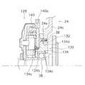
ローラブレーキ取付アダプタ30は、図3に示すように、ローラブレーキ装置28のブレーキドラム40を一体回転可能に装着するものである。アダプタ30は、ハブシェル24の側端部24cの内側面24dに装着されるフランジ部32と、フランジ部32に一体形成された筒状部34とを備えた鍔付き円筒状の部材である。フランジ部32には、周方向に間隔を隔てて配置された複数のねじ孔32aがハブ軸22と平行に形成されている。フランジ部32は、ハブシェル24の側端部24cの外側面24eから挿入された複数本の皿頭のねじ部材36をねじ孔32aにねじ込むことにより内側面24dに固定されている。 As shown in FIG. 3, the roller
筒状部34は、内周面に設けられ、ハブシェル24をハブ軸22に回転自在に支持する軸受38と接触する第1接触面34aと、外周面に設けられ、周方向に間隔を隔てて形成された凹凸部34bを有し、ローラブレーキ装置28へのブレーキドラム40と接触する第2接触面34cと有している。また、筒状部34は、ハブシェル24の側端部の内周面24fに接触する第3接触面34dを有している。 The
第1接触面34aは、ハブ軸22に内輪38aが装着された軸受38の外輪38bに接触している。第1接触面34aの少なくとも一部は、ハブシェル24の側端部24cの外側面より内側に配置されている。これにより、軸受38に作用するラジアル方向の力を受けやすくなる。 The
第2接触面34cは、筒状部34の外側端部の外周面に配置されており、第1接触面34aより外側で第1接触面34aと一部が径方向で重なり合うように配置されている。第2接触部34cの凹凸部34bは、いわゆるセレーションやスプラインと呼ばれる、たとえば1〜3mm程度の幅を有する凸部が周方向に間隔を隔てて形成されたものであり、ブレーキドラム40の内周面に噛み合ってブレーキドラム40をハブ軸22と一体回転させるために設けられている。 The
第3接触面34dは、フランジ部32と隣接する筒状部34の外周面に第2接触面34cより大径に形成されている。第3接触面34dは、アダプタ30を介してハブシェル24をハブ軸22と同芯に配置するために形成されている。この第3接触面34dが側端部24cの内周面24fに装着することによりハブシェル24がハブ軸22と同芯に配置される。 34 d of 3rd contact surfaces are formed in the outer peripheral surface of the
ローラブレーキ装置28は、図3から図5に示すように、ブレーキドラム40と、フレーム12に回転不能に装着される固定ブラケット42と、ブレーキドラム40に圧接して制動作用するブレーキシュー44と、ブレーキシュー44をブレーキドラム40に圧接させるブレーキ動作部46とを有している。 As shown in FIGS. 3 to 5, the
ブレーキドラム40は、図3に示すように、ハブシェル24と一体回転可能であり、内周面に制動面50aを有するリング状のドラム本体50と、ドラム本体50の外周側に固定された冷却ディスク52とを有している。制動面50aは、径方向外方にいくにつれて幅が狭くなる等脚台形状に中央部が凹んで形成されている。また、ブレーキシュー44の外周面は、逆に外周面が等脚台形状に突出して形成されている。ドラム本体50の内周面には、第2接触面34cの凹凸部34bに一体回転可能に係合する凹凸部50cが形成されている。制動面50aの最も凹んだ部分には、グリース充填溝50bが形成されている。冷却ディスク52は、好ましくはアルミニウム合金製であり、ドラム本体50にカシメ固定されドラム本体50を冷却するために設けられている。 As shown in FIG. 3, the
固定ブラケット42は、ハブ軸22に装着されかつフレーム12に回り止めされている。固定ブラケット42は、ブレーキシュー44を回り止めするとともに、ブレーキ動作部46を回動自在に支持する。固定ブラケット42は、ハブ軸22にねじ込まれる固定ナット80によりハブ軸22に装着される。 The fixed
ブレーキシュー44は、たとえば3つに分割されたリング状の部材であり、固定ブラケット42に回り止めされた状態で配置されている。ブレーキシュー44は、リターンばね54により制動面50aから離反する方向(径方向内方)に付勢されている。リターンばね54は、弾性線材を円形に湾曲して形成された環状のばね部材である。 The
ブレーキ動作部46は、リターンばね54により付勢されたブレーキシュー44を付勢力に抗して制動面50aに圧接するものである。図4及び図5に示すように、ブレーキ動作部46は、固定ブラケット42に揺動自在に装着された動作アーム部60(図4)と、動作アーム部60と一体回動するカム部材62と、カム部材62とブレーキシュー44との間に両者に接触しかつ周方向に間隔を隔てて配置された、複数(たとえば6つ)のローラ64と、ローラ64を周方向に間隔を隔てて保持するローラケース66とを有している。 The
動作アーム部60は、金属板状の部材であり、制動ケーブル70のインナーケーブル70aの一端が連結されている。インナーケーブル70aの他端は、ハンドル12bに装着されたブレーキレバー72(図1)に連結されている。カム部材62は、回動に応じてローラ64を径方向外方に押圧する、たとえば6つの傾斜面62aを外周面に有している。 The
ブレーキレバー72の操作によりインナーケーブル70aが引っ張られる(図4左方に移動する)と、動作アーム部60がハブ軸22回りに図4時計回りに揺動し、動作アーム部60と一体回動するカム部材62が回動してローラ64を径方向外方に移動させ、ブレーキシュー44をブレーキドラム40の制動面50aに圧接させる。ブレーキレバー72を解放すると、インナーケーブル70aが元に戻り動作アーム部60が図4反時計回りに揺動する。この結果、ローラ64による押圧が解除され、リターンばね54によりブレーキシュー44は、制動面50aから離反する径方向内方に移動する。 When the inner cable 70a is pulled by the operation of the brake lever 72 (moves to the left in FIG. 4), the
上記のように構成されたローラブレーキ取付アダプタ30を装着する場合には、ハブシェル24にねじ部材36を用いて装着すると、第1接触面34aと第2接触面34cとが内周面と外周面とに各別に配置される。この第1接触面34aに軸受38を装着してハブ軸22に対してハブシェル24を回転自在に支持する。 When mounting the roller
また、ローラブレーキ装置28を装着する際には、第2接触面34cの凹凸部34bにドラム本体50の凹凸部50cを係合させて装着する。これにより、ハブシェル24とブレーキドラム40とが一体回転可能になる。そして、固定ナット80をハブ軸22にねじ込むことによりローラブレーキ装置28がハブ軸に装着される。さらに、回り止めするために固定ブラケットの先端をフレーム12に固定する。これによりローラブレーキ装置28の装着が完了する。 Further, when the
ここでは、フランジ部32と筒状部34とでアダプタ30を構成し、筒状部34の第2接触面34cに凹凸部34bを設けたので、通常のバンドブレーキより強いブレーキ力を有するローラブレーキ装置28であっても、簡単にモータ内蔵ハブ20に取り付けることができる。 Here, since the
また、第1接触面34aの少なくとも一部がハブシェル24の側端部24cの外側面24eより内側に配置されているので、軸受38の少なくとも一部が外側面より内側に配置され、軸受38に作用するラジアル方向の力を受けやすくなる。 Further, since at least a part of the
<他の実施形態>
(a)前記実施形態では、後輪に装着されるモータ内蔵ハブに取り付けられるローラブレーキアダプタを例に説明したが、前輪に装着されるモータ内蔵ハブに取り付けられるローラブレーキ取付アダプタにも本発明を適用できる。<Other embodiments>
(A) In the above embodiment, the roller brake adapter attached to the motor built-in hub attached to the rear wheel has been described as an example. However, the present invention is also applied to the roller brake attachment adapter attached to the motor built-in hub attached to the front wheel. Applicable.
(b)前記実施形態では、アダプタ30は、ハブシェル24の側端部24cの内側面24dに装着されていた。しかし、図6に示すように、ローラブレーキ取付アダプタ130を側端部24cの外側面24eにねじ部材36により装着してもよい。アダプタ130は、フランジ部132と、フランジ部132を中心に左右に延びる筒状部134とを有している。筒状部132の内周面には、第1接触面132aが形成され、外周面には、フランジ部132を挟んで第2接触面134cと第3接触面134dとが配置されている。これらの形状は前記実施形態と同様である。 (B) In the above embodiment, the
なお、図6では、ローラブレーキ装置128は、ブレーキドラム140は、冷却ディスクを有しておらず、ブレーキドラム140の制動面140aが平坦な円周面で構成されている。したがって、ブレーキシューの外周面も平坦な円周面である。その他の構成が前記実施形態と同様である。 In FIG. 6, in the
20 モータ内蔵ハブ
24 ハブシェル
24c 側端部
24d 内側面
24e 外側面
30 ローラブレーキ取付アダプタ
32 フランジ部
34 筒状部
34a 第1接触面
34b 凹凸部
34c 第2接触面
36 ねじ部材DESCRIPTION OF
Claims (7)
Translated fromJapanese前記ハブのハブシェルの側端部に装着されるフランジ部と、
前記フランジ部に一体形成された筒状部と、を備え、
前記筒状部は、
内周面に設けられ、前記ハブシェルを前記ハブ軸に回転自在に支持する軸受と接触する第1接触面と、
外周面に設けられ、周方向に間隔を隔てて形成された凹凸部を有し、前記ローラブレーキ装置のブレーキドラムと接触する第2接触面と、
を有することを特徴とする、ローラブレーキ取付アダプタ。A roller brake mounting adapter that can be mounted on a bicycle motor built-in hub,
A flange portion attached to a side end portion of the hub shell of the hub;
A cylindrical portion integrally formed with the flange portion,
The cylindrical part is
A first contact surface that is provided on an inner peripheral surface and contacts a bearing that rotatably supports the hub shell on the hub shaft;
A second contact surface provided on the outer peripheral surface, having a concavo-convex portion formed at an interval in the circumferential direction, and in contact with the brake drum of the roller brake device;
A roller brake mounting adapter, comprising:
Priority Applications (4)
| Application Number | Priority Date | Filing Date | Title |
|---|---|---|---|
| JP2005177231AJP2006347412A (en) | 2005-06-17 | 2005-06-17 | Roller brake mounting adapter |
| US11/390,119US7540361B2 (en) | 2005-06-17 | 2006-03-28 | Roller brake mounting adapter |
| TW095116418ATW200706443A (en) | 2005-06-17 | 2006-05-09 | Roller brake mounting adapter |
| EP20060012176EP1733957B1 (en) | 2005-06-17 | 2006-06-13 | Roller brake mounting adapter |
Applications Claiming Priority (1)
| Application Number | Priority Date | Filing Date | Title |
|---|---|---|---|
| JP2005177231AJP2006347412A (en) | 2005-06-17 | 2005-06-17 | Roller brake mounting adapter |
Publications (1)
| Publication Number | Publication Date |
|---|---|
| JP2006347412Atrue JP2006347412A (en) | 2006-12-28 |
Family
ID=37643689
Family Applications (1)
| Application Number | Title | Priority Date | Filing Date |
|---|---|---|---|
| JP2005177231APendingJP2006347412A (en) | 2005-06-17 | 2005-06-17 | Roller brake mounting adapter |
Country Status (2)
| Country | Link |
|---|---|
| US (1) | US7540361B2 (en) |
| JP (1) | JP2006347412A (en) |
Cited By (5)
| Publication number | Priority date | Publication date | Assignee | Title |
|---|---|---|---|---|
| EP2436592A1 (en) | 2010-09-30 | 2012-04-04 | Sanyo Electric Co., Ltd. | Electric bicycle hub unit, and electric bicycle including the hub |
| WO2014033818A1 (en)* | 2012-08-27 | 2014-03-06 | 株式会社 島津製作所 | Irreversible mechanism |
| JP2018091428A (en)* | 2016-12-05 | 2018-06-14 | 日本精工株式会社 | Electromagnetic brake |
| JP2020179814A (en)* | 2019-04-26 | 2020-11-05 | 株式会社シマノ | Wheel unit for man powered vehicle and wheel assembly for man powered vehicle |
| JP7573120B2 (en) | 2022-03-07 | 2024-10-24 | 唐澤交通器材(泰州)有限公司 | Clutch-type extendable brake for bicycles |
Families Citing this family (2)
| Publication number | Priority date | Publication date | Assignee | Title |
|---|---|---|---|---|
| JP5149938B2 (en)* | 2010-06-11 | 2013-02-20 | 株式会社シマノ | Bicycle hub with built-in motor |
| DE102014011336A1 (en)* | 2014-07-30 | 2016-02-04 | Liebherr-Aerospace Lindenberg Gmbh | Backstop with radially acting brake elements |
Family Cites Families (17)
| Publication number | Priority date | Publication date | Assignee | Title |
|---|---|---|---|---|
| US1816643A (en)* | 1922-05-18 | 1931-07-28 | Steel Wheel Corp | Disk wheel |
| JPS61146634U (en)* | 1985-03-04 | 1986-09-10 | ||
| JP2596533Y2 (en) | 1993-08-11 | 1999-06-14 | 株式会社シマノ | Internally expandable hub brake for bicycles |
| JP2597742Y2 (en) | 1993-08-11 | 1999-07-12 | 株式会社シマノ | Bicycle hub brake |
| JP3638309B2 (en) | 1994-06-23 | 2005-04-13 | 株式会社シマノ | Bicycle hub brake |
| JP2914909B2 (en) | 1996-03-15 | 1999-07-05 | 株式会社シマノ | Gearbox for bicycle transmission |
| US5890567A (en)* | 1998-01-12 | 1999-04-06 | Gunite Corporation | Brake drum mounting |
| JP3477134B2 (en)* | 2000-01-31 | 2003-12-10 | 株式会社シマノ | Bicycle hub |
| JP2002220081A (en) | 2001-01-26 | 2002-08-06 | Sanyo Electric Co Ltd | Vehicle with auxiliary power |
| JP3682957B2 (en) | 2001-09-12 | 2005-08-17 | 株式会社シマノ | Bicycle hub brake device |
| JP3784348B2 (en) | 2002-06-11 | 2006-06-07 | 株式会社シマノ | Bicycle hub brake device mounting structure |
| JP3740092B2 (en) | 2002-06-11 | 2006-01-25 | 株式会社シマノ | Bicycle hub brake device |
| JP3703780B2 (en) | 2002-06-11 | 2005-10-05 | 株式会社シマノ | Bicycle hub brake device |
| JP3720002B2 (en) | 2002-06-11 | 2005-11-24 | 株式会社シマノ | Bicycle hub brake device |
| JP2004025941A (en) | 2002-06-21 | 2004-01-29 | Sanyo Electric Co Ltd | Drive for power-assisted bicycle |
| JP3696189B2 (en)* | 2002-08-26 | 2005-09-14 | 株式会社シマノ | Bicycle hub dynamo |
| JP2005075106A (en) | 2003-08-29 | 2005-03-24 | Shimano Inc | Bicycle hub generator |
- 2005
- 2005-06-17JPJP2005177231Apatent/JP2006347412A/enactivePending
- 2006
- 2006-03-28USUS11/390,119patent/US7540361B2/ennot_activeExpired - Fee Related
Cited By (9)
| Publication number | Priority date | Publication date | Assignee | Title |
|---|---|---|---|---|
| EP2436592A1 (en) | 2010-09-30 | 2012-04-04 | Sanyo Electric Co., Ltd. | Electric bicycle hub unit, and electric bicycle including the hub |
| US20120080252A1 (en)* | 2010-09-30 | 2012-04-05 | Sanyo Consumer Electronics Co., Ltd. | Electric bicycle hub unit, and electric bicycle including the hub unit |
| WO2014033818A1 (en)* | 2012-08-27 | 2014-03-06 | 株式会社 島津製作所 | Irreversible mechanism |
| JPWO2014033818A1 (en)* | 2012-08-27 | 2016-08-08 | 株式会社島津製作所 | Irreversible mechanism |
| US9470280B2 (en) | 2012-08-27 | 2016-10-18 | Shimadzu Corporation | Irreversible mechanism |
| JP2018091428A (en)* | 2016-12-05 | 2018-06-14 | 日本精工株式会社 | Electromagnetic brake |
| JP2020179814A (en)* | 2019-04-26 | 2020-11-05 | 株式会社シマノ | Wheel unit for man powered vehicle and wheel assembly for man powered vehicle |
| JP7321756B2 (en) | 2019-04-26 | 2023-08-07 | 株式会社シマノ | Wheel units for man-powered vehicles and wheel assemblies for man-powered vehicles |
| JP7573120B2 (en) | 2022-03-07 | 2024-10-24 | 唐澤交通器材(泰州)有限公司 | Clutch-type extendable brake for bicycles |
Also Published As
| Publication number | Publication date |
|---|---|
| US7540361B2 (en) | 2009-06-02 |
| US20070017755A1 (en) | 2007-01-25 |
Similar Documents
| Publication | Publication Date | Title |
|---|---|---|
| TWI311968B (en) | ||
| JP3732182B2 (en) | Bicycle hub | |
| US7854302B2 (en) | Apparatus for mounting a hub brake to a bicycle frame | |
| JP4414257B2 (en) | Wheel speed sensor mounting structure for motorcycles | |
| JP2010159794A (en) | Transfer with built-in wet brake | |
| US7540361B2 (en) | Roller brake mounting adapter | |
| JP2007297031A (en) | Disk brake hub for bicycle | |
| JP6179703B2 (en) | Electric hub device and electric bicycle | |
| JP4476576B2 (en) | Parking brake structure | |
| JP5546491B2 (en) | Electric parking brake device | |
| EP1733957B1 (en) | Roller brake mounting adapter | |
| JP6105322B2 (en) | Power transmission device for saddle-ride type hybrid vehicle | |
| CN100534855C (en) | Wheel drive device for bicycle | |
| JP5363388B2 (en) | Brake panel structure of drum brake | |
| JP5204833B2 (en) | Brake structure of wheel rotation device | |
| EP1980482B1 (en) | Bicycle wheel driving device | |
| JP4221399B2 (en) | Bicycle hub cover | |
| JP5092007B2 (en) | Brake structure of wheel rotation device | |
| CN2454265Y (en) | bicycle drive sprocket | |
| EP1733962A2 (en) | Bicycle wheel driving device | |
| CN1880160A (en) | Mounting and connection parts for roller type brake | |
| JP2001012522A (en) | Automatic adjustment device for braking gap in braking device for saddle boarding type vehicle | |
| JPS6126152Y2 (en) | ||
| JP2007230558A (en) | Brake structure for motorcycle | |
| JP2003034282A (en) | Connecting structure of gear unit for meter cable |
Legal Events
| Date | Code | Title | Description |
|---|---|---|---|
| A977 | Report on retrieval | Free format text:JAPANESE INTERMEDIATE CODE: A971007 Effective date:20080623 | |
| A131 | Notification of reasons for refusal | Free format text:JAPANESE INTERMEDIATE CODE: A131 Effective date:20080701 | |
| A521 | Written amendment | Free format text:JAPANESE INTERMEDIATE CODE: A523 Effective date:20080829 | |
| RD02 | Notification of acceptance of power of attorney | Free format text:JAPANESE INTERMEDIATE CODE: A7422 Effective date:20080829 | |
| A02 | Decision of refusal | Free format text:JAPANESE INTERMEDIATE CODE: A02 Effective date:20090811 |