JP2006345172A - Viewfinder device and camera - Google Patents
Viewfinder device and cameraDownload PDFInfo
- Publication number
- JP2006345172A JP2006345172AJP2005168267AJP2005168267AJP2006345172AJP 2006345172 AJP2006345172 AJP 2006345172AJP 2005168267 AJP2005168267 AJP 2005168267AJP 2005168267 AJP2005168267 AJP 2005168267AJP 2006345172 AJP2006345172 AJP 2006345172A
- Authority
- JP
- Japan
- Prior art keywords
- imaging
- finder
- light
- image
- display
- Prior art date
- Legal status (The legal status is an assumption and is not a legal conclusion. Google has not performed a legal analysis and makes no representation as to the accuracy of the status listed.)
- Pending
Links
- 238000003384imaging methodMethods0.000claimsabstractdescription58
- 229920006395saturated elastomerPolymers0.000claimsabstractdescription7
- 230000003287optical effectEffects0.000claimsdescription40
- 230000035945sensitivityEffects0.000claimsdescription21
- 238000000034methodMethods0.000description27
- 230000008569processEffects0.000description25
- 239000004973liquid crystal related substanceSubstances0.000description16
- 230000007246mechanismEffects0.000description16
- 238000012545processingMethods0.000description12
- 230000006870functionEffects0.000description8
- 238000005375photometryMethods0.000description7
- 238000005259measurementMethods0.000description6
- 230000008859changeEffects0.000description5
- 238000010586diagramMethods0.000description5
- 230000004907fluxEffects0.000description5
- 230000011514reflexEffects0.000description5
- 238000004891communicationMethods0.000description4
- 238000012937correctionMethods0.000description3
- 238000006243chemical reactionMethods0.000description2
- 238000012544monitoring processMethods0.000description2
- 230000001419dependent effectEffects0.000description1
- 238000001514detection methodMethods0.000description1
- 230000006872improvementEffects0.000description1
- 230000009467reductionEffects0.000description1
- 230000001360synchronised effectEffects0.000description1
Images


Classifications
- G—PHYSICS
- G03—PHOTOGRAPHY; CINEMATOGRAPHY; ANALOGOUS TECHNIQUES USING WAVES OTHER THAN OPTICAL WAVES; ELECTROGRAPHY; HOLOGRAPHY
- G03B—APPARATUS OR ARRANGEMENTS FOR TAKING PHOTOGRAPHS OR FOR PROJECTING OR VIEWING THEM; APPARATUS OR ARRANGEMENTS EMPLOYING ANALOGOUS TECHNIQUES USING WAVES OTHER THAN OPTICAL WAVES; ACCESSORIES THEREFOR
- G03B17/00—Details of cameras or camera bodies; Accessories therefor
- G03B17/18—Signals indicating condition of a camera member or suitability of light
- G03B17/20—Signals indicating condition of a camera member or suitability of light visible in viewfinder
- G—PHYSICS
- G03—PHOTOGRAPHY; CINEMATOGRAPHY; ANALOGOUS TECHNIQUES USING WAVES OTHER THAN OPTICAL WAVES; ELECTROGRAPHY; HOLOGRAPHY
- G03B—APPARATUS OR ARRANGEMENTS FOR TAKING PHOTOGRAPHS OR FOR PROJECTING OR VIEWING THEM; APPARATUS OR ARRANGEMENTS EMPLOYING ANALOGOUS TECHNIQUES USING WAVES OTHER THAN OPTICAL WAVES; ACCESSORIES THEREFOR
- G03B13/00—Viewfinders; Focusing aids for cameras; Means for focusing for cameras; Autofocus systems for cameras
- G03B13/02—Viewfinders
- G03B13/06—Viewfinders with lenses with or without reflectors
- H—ELECTRICITY
- H04—ELECTRIC COMMUNICATION TECHNIQUE
- H04N—PICTORIAL COMMUNICATION, e.g. TELEVISION
- H04N23/00—Cameras or camera modules comprising electronic image sensors; Control thereof
- H04N23/60—Control of cameras or camera modules
- H04N23/63—Control of cameras or camera modules by using electronic viewfinders
- H04N23/631—Graphical user interfaces [GUI] specially adapted for controlling image capture or setting capture parameters
- H—ELECTRICITY
- H04—ELECTRIC COMMUNICATION TECHNIQUE
- H04N—PICTORIAL COMMUNICATION, e.g. TELEVISION
- H04N23/00—Cameras or camera modules comprising electronic image sensors; Control thereof
- H04N23/60—Control of cameras or camera modules
- H04N23/63—Control of cameras or camera modules by using electronic viewfinders
- H04N23/633—Control of cameras or camera modules by using electronic viewfinders for displaying additional information relating to control or operation of the camera
- H04N23/635—Region indicators; Field of view indicators
Landscapes
- Engineering & Computer Science (AREA)
- Multimedia (AREA)
- Signal Processing (AREA)
- Physics & Mathematics (AREA)
- General Physics & Mathematics (AREA)
- Human Computer Interaction (AREA)
- Viewfinders (AREA)
- Studio Devices (AREA)
Abstract
Description
Translated fromJapanese本発明はファインダ装置に関し、より詳細には観察中の画像と撮影中の画像とを表示画面に表示可能なデジタルカメラのファインダ装置の改良に関するものである。 The present invention relates to a viewfinder device, and more particularly to an improvement in a viewfinder device of a digital camera that can display an image being observed and an image being shot on a display screen.
従来より、撮影レンズ等の撮影光学系により結像される被写体像を、撮像素子によって光電変換し、これにより得られた画像信号に基づいて液晶モニタ等の画像表示装置に表示するカメラが一般的に知られている。 2. Description of the Related Art Conventionally, a camera that subjects a subject image formed by a photographing optical system such as a photographing lens to photoelectric conversion by an image sensor and displays it on an image display device such as a liquid crystal monitor based on an image signal obtained thereby is generally used. Known to.
こうした被写体像を表示するカメラとしては、本露出用の露出手段とは別に、被写界のモニタ用に別の撮像手段を設けてファインダ光学系内にハーフミラーを配置し、ライブビュー表示用の撮像素子に被写体光束を導くカメラが知られている。この場合、ライブビューモードでは、撮像素子によって繰り返し撮像を行い、表示装置に表示するものである(例えば、特許文献1参照)。 As a camera for displaying such a subject image, in addition to the exposure means for the main exposure, another imaging means is provided for monitoring the object field, a half mirror is arranged in the finder optical system, and a live view display is provided. A camera that guides a subject luminous flux to an image sensor is known. In this case, in the live view mode, images are repeatedly picked up by the image pickup device and displayed on the display device (see, for example, Patent Document 1).
また、ファインダスクリーンを、別の撮像素子でモニタするという技術も知られている(例えば、特許文献2参照)。
従来の一眼レフレックスタイプのカメラ(以下、単に一眼レフカメラと略記する)に於いては、ファインダ内に多点測距の合焦ポイントを表示するためのスーパーインポーズ表示や、撮影情報の表示を行うのが一般的であった。 In conventional single-lens reflex type cameras (hereinafter simply abbreviated as single-lens reflex cameras), superimpose display for displaying the focus point of multi-point distance measurement and display of shooting information in the viewfinder It was common to do.
ところが、上述した特許文献1に記載のカメラでは、撮影情報等を被写体像と同時に表示装置に表示するものではなかった。 However, the camera described in
また、上記特許文献2に記載の技術のように、ファインダスクリーンを別の撮像素子でモニタすると、ファインダ内の表示の輝度と被写界輝度とが合わないことがある。そのため、上述した撮影情報等の表示が弱すぎて見え難かったり、強すぎてにじんでしまって見え難かったりすることがあった。 Further, when the finder screen is monitored with another image sensor as in the technique described in
したがって、本発明の目的は、被写体画像の表示と撮影情報等の表示が見え難くなることなく、高品位のライブビュー表示機能を有するファインダ装置及びカメラを提供することである。 Accordingly, an object of the present invention is to provide a finder device and a camera having a high-quality live view display function without making it difficult to see the display of the subject image and the shooting information.
すなわち請求項1に記載の発明は、ファインダ光路内に配置され、被写体像を結像するスクリーンマットと、上記スクリーンマット上の被写体像を含むファインダ画像を繰り返し取得する撮像手段と、上記撮像手段で取得された画像データを表示する画像表示手段と、上記ファインダ内に配置された発光表示手段と、を具備するファインダ装置に於いて、上記発光表示手段は、発光表示動作を行った際に上記撮像手段の受光レベルが飽和しないように、その発光量を調整可能であることを特徴とする。 That is, the invention described in
請求項2に記載の発明は、請求項1に記載の発明に於いて、上記発光表示手段は、上記スクリーンマット上に投光するLEDと、該LEDの光量を調整可能な駆動回路とを含むことを特徴とする。 According to a second aspect of the present invention, in the first aspect of the present invention, the light emitting display means includes an LED that projects light on the screen mat, and a drive circuit that can adjust the light quantity of the LED. It is characterized by that.
請求項3に記載の発明は、請求項1に記載の発明に於いて、上記発光表示手段は、上記スクリーンマットに隣接するLCD表示素子と、該LCD表示素子のための光量調整可能なバックライト素子とを含むことを特徴とする。 According to a third aspect of the present invention, in the first aspect of the present invention, the light emitting display means includes an LCD display element adjacent to the screen mat and a light amount adjustable backlight for the LCD display element. And an element.
請求項4に記載の発明は、請求項1に記載の発明に於いて、上記撮像手段は、被写体の明るさに応じて撮像感度を自動調整する機能を有し、上記発光表示手段は上記撮像手段の撮像感度に応じて上記発光量を調整することを特徴とする。 According to a fourth aspect of the present invention, in the first aspect of the present invention, the imaging unit has a function of automatically adjusting imaging sensitivity according to the brightness of a subject, and the light emitting display unit is configured to capture the imaging. The light emission amount is adjusted according to the imaging sensitivity of the means.
請求項5に記載の発明は、請求項4に記載の発明に於いて、上記撮像手段は、上記発光表示動作の際、上記撮像感度の自動調整を停止することを特徴とする。 According to a fifth aspect of the present invention, in the invention according to the fourth aspect, the imaging means stops the automatic adjustment of the imaging sensitivity during the light emitting display operation.
請求項6に記載の発明は、請求項1乃至4の何れか1に記載の発明に於けるファインダ装置を具備することを特徴とする。 According to a sixth aspect of the present invention, the finder device according to any one of the first to fourth aspects is provided.
請求項7に記載の発明は、ファインダ光路内に配置され、被写体像を結像するスクリーンマットと、上記スクリーンマット上の被写体像を含むファインダ画像を繰り返し取得する撮像手段と、上記撮像手段で取得された画像データを表示する画像表示手段と、上記ファインダ光路内に配置されて情報表示を行う発光表示手段と、上記スクリーンマット上の被写体像及び上記発光表示手段により表示された情報を観察するためのファインダ光学系と、上記発光表示手段の発光表示動作を行った際に上記撮像手段の受光レベルが飽和しないように、その発光量を制御する制御手段と、を具備することを特徴とする。 According to a seventh aspect of the present invention, a screen mat that is disposed in the finder optical path and forms a subject image, an imaging unit that repeatedly acquires a finder image including the subject image on the screen mat, and an acquisition unit that acquires the image. For observing information displayed by the image display means for displaying the image data, the light emission display means for displaying information arranged in the finder optical path, the subject image on the screen mat and the light emission display means And a control means for controlling the amount of light emission so that the light receiving level of the image pickup means is not saturated when the light emission display operation of the light emission display means is performed.
請求項8に記載の発明は、請求項7に記載の発明に於いて、上記発光表示手段は、上記スクリーンマット上に投光するLEDと、該LEDの光量を調整可能な駆動回路とを含むことを特徴とする。 The invention according to
請求項9に記載の発明は、請求項7に記載の発明に於いて、上記発光表示手段は、上記スクリーンマットに隣接するLCD表示素子と、該LCD表示素子のための光量調整可能なバックライト素子とを含むことを特徴とする。 The invention according to
請求項10に記載の発明は、請求項7に記載の発明に於いて、上記撮像手段は、被写体の明るさに応じて撮像感度を自動調整する機能を有し、上記制御手段は上記撮像手段の撮像感度に応じて上記発光表示手段の発光量を制御することを特徴とする。 According to a tenth aspect of the present invention, in the seventh aspect of the invention, the imaging means has a function of automatically adjusting imaging sensitivity in accordance with the brightness of the subject, and the control means is the imaging means. The light emission amount of the light emission display means is controlled according to the imaging sensitivity.
請求項11に記載の発明は、請求項10に記載の発明に於いて、上記撮像手段は、上記発光表示動作の際、上記撮像感度の自動調整を停止することを特徴とする。 According to an eleventh aspect of the invention, in the tenth aspect of the invention, the imaging means stops automatic adjustment of the imaging sensitivity during the light emission display operation.
本発明によれば、被写体画像の表示と撮影情報等の表示が見え難くなることなく、使い勝手のよい高品位のライブビュー表示機能を有するファインダ装置及びカメラを提供することができる。 According to the present invention, it is possible to provide a finder apparatus and a camera having a high-quality live view display function that is easy to use without making it difficult to see the display of subject images and shooting information.
以下、図面を参照して、本発明の実施形態を説明する。 Hereinafter, embodiments of the present invention will be described with reference to the drawings.
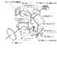
図1は、本発明の一実施形態を示すもので、本発明のファインダ装置が適用された一眼レフレックスタイプのデジタルカメラの構成を示す外観斜視図である。 FIG. 1 shows an embodiment of the present invention, and is an external perspective view showing a configuration of a single-lens reflex digital camera to which a finder device of the present invention is applied.
図1に於いて、この一眼レフレックスタイプのデジタルカメラ(以下、カメラと略記する)1は、交換レンズとしてのレンズ鏡筒10と、カメラ本体30から主に構成されており、該カメラ本体30の前面に対して、所望のレンズ鏡筒10が着脱自在に設定されている。
カメラ本体30の上面には、レリーズ釦31と、モードダイヤル32と、パワースイッチレバー33と、コントロールダイヤル34等が設けられている。In FIG. 1, this single-lens reflex digital camera (hereinafter abbreviated as “camera”) 1 is mainly composed of a
On the upper surface of the camera body 30, a release button 31, a mode dial 32, a power switch lever 33, a control dial 34, and the like are provided.
レリーズ釦31は、撮影準備動作及び露光動作を実行させるための釦である。このレリーズ釦31は、第1レリーズスイッチと第2レリーズスイッチの2段式のスイッチで構成されており、レリーズ釦31が半押し操作されることによって、第1レリーズスイッチがオンされて測光処理や測距処理などの撮影準備動作が実行される。また、レリーズ釦31が全押し操作されることによって、第2レリーズスイッチがオンされて露光動作が実行される。 The release button 31 is a button for executing a shooting preparation operation and an exposure operation. The release button 31 is composed of a two-stage switch of a first release switch and a second release switch. When the release button 31 is pressed halfway, the first release switch is turned on to perform photometric processing or Shooting preparation operations such as distance measurement processing are executed. Further, when the release button 31 is fully pressed, the second release switch is turned on and the exposure operation is executed.
モードダイヤル32は、撮影時の撮影モードを設定するための操作部材である。このモードダイヤル32が所定方向に回転操作されることによって、撮影時の撮影モードが設定される。本実施形態に於いては、後述する液晶モニタに表示される画像を、ファインダビューとライブビューとで切り換える機能も有している。パワースイッチレバー33は、当該カメラ1の電源のオン/オフをするための操作部材である。このパワースイッチレバー33が回動操作されることにより、当該カメラ1のメイン電源のオン/オフが切り換えられる。 The mode dial 32 is an operation member for setting a shooting mode at the time of shooting. When the mode dial 32 is rotated in a predetermined direction, a shooting mode at the time of shooting is set. The present embodiment also has a function of switching an image displayed on a liquid crystal monitor (to be described later) between a viewfinder view and a live view. The power switch lever 33 is an operation member for turning on / off the power of the
コントロールダイヤル34は、撮影情報の設定を行うための部材である。このコントロールダイヤル34が操作されることにより、撮影時に種々の設定が行われる。 The control dial 34 is a member for setting shooting information. By operating the control dial 34, various settings are performed during shooting.
ボディユニット30の背面部には、撮影画像やメニュー等を表示するための液晶モニタ36と、再生釦37と、メニュー釦38と、十字キー40と、OK釦41と、接眼光学系のファインダ43等が配置されている。 On the back surface of the body unit 30, a
上記再生釦37は、カメラ1の動作モードを、後述するFlashMemory84や記録メディア85に記録されたJPEGファイルから画像を再生できる再生モードに切り換えるための釦である。メニュー釦38は、液晶モニタ36にメニュー画面を表示させるための釦である。このメニュー画面は、複数の階層構造から成るメニュー項目によって構成されている。ユーザは、所望のメニュー項目を十字キー40で選択することができ、OK釦41で選択した項目を決定することができる。 The
図2は、本発明の一実施形態に於けるカメラのファインダ光学系の構成を示す斜視図である。 FIG. 2 is a perspective view showing the configuration of the finder optical system of the camera in one embodiment of the present invention.
ファインダ光学系50は、レンズ鏡筒内の撮影レンズ11を通過した被写体からの光束を、上記ファインダ43を構成する接眼レンズ57へと導くための複数のミラー、すなわち第1反射ミラー51、第2反射ミラー52、第3反射ミラー53、第4反射ミラー54と、フォーカシングスクリーン(スクリーンマット)56と、接眼レンズ57とを有して構成される。 The viewfinder
上記第1反射ミラー51は軸51aを中心に図示矢印A方向に回動可能に構成されるもので、その一部が後述するAFセンサユニット71のためにハーフミラーで構成されている。第1反射ミラー51は、被写体の観察時は図示の如く、撮影レンズ11から入射された光束を、撮影レンズ11の光軸に対し略90°の角度である第2反射ミラー52の方向、すなわちカメラ本体30のレンズ鏡筒10側より見て右方向に反射する。そして、撮像時は、撮影光路より退避されて、被写体からの光束が、第1反射ミラー51の後方に配置される撮像素子(図示せず)に導かれるように動作する。 The first reflecting
上記第1反射ミラー51の反射面で反射された光束は、フォーカシングスクリーン56を介して第2反射ミラー52に入射する。この第2反射ミラー52は、上記第1反射ミラー51からの反射光軸上であって、その反射面が上記第1反射ミラー51の反射光軸に対し、所定の角度だけ傾いて配置されている。第2反射ミラー52に入射された上記第1反射ミラー51からの反射光束は、該第1反射ミラー51からの反射光軸に対し略90°の角度、すなわちカメラ本体30の上方に向けて反射される。 The light beam reflected by the reflecting surface of the first reflecting
上記第2反射ミラー52の反射面で反射された光束は、該第2反射ミラー52の反射面の反射光軸上であって、その反射面が第2の反射面の反射光軸に対し所定の角度だけ傾いて配置される第3反射ミラー53に入射される。第3反射ミラー53に入射された第2反射ミラー52からの反射光束は、第3反射ミラー53の反射面にて、上記第2反射ミラー52の反射面からの反射光軸に対し略90°の角度であって、上記第1反射ミラー51の反射面による反射方向と相反する方向に反射される。つまり、第2反射ミラー52の反射面からの反射光束は、第3反射ミラー53の反射面にて、カメラ本体30の左方向に向けて反射される。換言すれば、第1反射ミラー51の反射面にて反射された光束は、第2、第3反射ミラー52、53によって折り返すように導かれ、第3反射ミラー53の反射面の反射光軸は、上記第1反射ミラー51の反射面の反射光軸と略平行となって第4反射ミラー54に向かう。 The light beam reflected by the reflecting surface of the second reflecting mirror 52 is on the reflecting optical axis of the reflecting surface of the second reflecting mirror 52, and the reflecting surface is predetermined with respect to the reflecting optical axis of the second reflecting surface. It is incident on the third reflecting
上記第3反射ミラー53の反射面で反射された光束は、該第3反射ミラー53の反射面の反射光軸上であって、その反射面が上記第3反射ミラー53の反射面の反射光軸に対し所定の角度だけ傾いて配置される第4反射ミラー54に入射される。そして、第4反射ミラー54に入射された上記第3反射ミラー53からの反射光束は、第4反射ミラー54の反射面にて、上記第3反射ミラー53からの反射光軸に対し略90°の角度に反射される。つまり、第3反射ミラー53の反射面からの反射光束は、第4反射ミラーの反射面の反射光軸上に配置された接眼レンズ57に入射される。 The light beam reflected by the reflecting surface of the third reflecting
上記フォーカシングスクリーン56は、上述したファインダ光学系50に入射された光束を光学像として結像させるために、該光束を拡散させる拡散面を有するもので、後述する撮影用撮像素子67の撮像面上と光学的に等価な位置に配置されている。更に、フォーカシングスクリーン56に隣接して、撮影情報等を表示するためのファインダ(F)内LCDパネル64及びこのF内LCDパネル64を照明するバックライトLED65が配設されている。 The focusing
また、上記第2反射ミラー52と第4反射ミラー54は、ハーフミラーで構成されている。第2反射ミラー52の反射面の裏面側には、合焦表示用LED62と、被写体の明るさを測定する測光センサ63とが配置されている。上記合焦表示用LED62は、画面の何処に合焦点があるかをスーパーインポーズ表示するためのものである。一方、第4反射ミラー54の反射面の裏面側には、結像レンズ60及びスルー画表示用撮像素子61が配設されている。このスルー画表示用撮像素子61は、フォーカシングスクリーン56上の像を、結像レンズ60を介して結像するためのものである。したがって、スルー画表示用撮像素子61に結像された像は反転しているものの、撮影者の目58が見ている像と同じものとなる。 The second reflection mirror 52 and the fourth reflection mirror 54 are half mirrors. On the back side of the reflecting surface of the second reflecting mirror 52, a
このように、撮影レンズ11からの被写体光束は、上述した第1乃至第4反射ミラー51〜54によって、その像が正立正像となるように反転されて接眼レンズ57に導かれる。これにより、接眼レンズ57(ファインダ43)を通して、撮影者の眼58でフォーカシングスクリーン56上に結像した被写体像が観察可能となる。 In this way, the subject luminous flux from the photographing
尚、本実施形態では、第1反射ミラー51、第2反射ミラー52、第3反射ミラー53及び第4反射ミラー54は、入射光束に対して略90°の角度で反射するように配置しているが、これに限られるものではない。 In the present embodiment, the first reflecting
図3は、本発明の一実施形態に係るカメラのシステム構成を示すブロック図である。 FIG. 3 is a block diagram showing the system configuration of the camera according to one embodiment of the present invention.
図3に於いて、上記レンズ鏡筒10は、上記カメラ本体30の前面に設けられた、図示されないレンズマウントを介して着脱自在に装着可能である。そして、上記レンズ鏡筒10は、撮影レンズ11と、絞り12と、レンズ駆動機構13と、絞り駆動機構14と、レンズ制御用マイクロコンピュータ(以下、Lμcomと略記する)15とから構成されている。 In FIG. 3, the
上記撮影レンズ11は、レンズ駆動機構13内に存在する図示されないDCモータによって、光軸方向に駆動される。絞り12は、絞り駆動機構14内に存在する図示されないステッピングモータによって駆動される。また、Lμcom15は、上記レンズ駆動機構13や絞り駆動機構14等、レンズ鏡筒10内の各部を駆動制御する。このLμcom15は、通信コネクタ20を介して、後述するボディ制御用マイクロコンピュータ80と電気的に接続がなされ、該ボディ制御用マイクロコンピュータ80の指令に従って制御される。 The photographing
一方、カメラ本体30は、以下のように構成されている。 On the other hand, the camera body 30 is configured as follows.
レンズ鏡筒10内の撮影レンズ11、絞り12を介して入射される図示されない被写体からの光束は、可動ミラーである第1反射ミラー51で反射され、フォーカシングスクリーン56、更に上記第1反射ミラー51と共にファインダ光学系50を構成する第2乃至第4反射ミラー52〜54(図2参照)等を介して、接眼レンズ57に至る。また、第1反射ミラー51のハーフミラーの部分を透過した被写体光束の一部は、第1反射ミラー51とは独立して作動するサブミラー70で反射されて、自動測距を行うためのAFセンサユニット71に導かれる。尚、図3に於いては、第1反射ミラー51は別に示されているが、第2乃至第4の反射ミラー等と共にファインダ光学系50を構成しているものである。 A light beam from a subject (not shown) that is incident through the photographing
光軸上で上記第1反射ミラー51の後方には、フォーカルプレーン式のシャッタ66と、光学系を通過した被写体像を光電変換するための撮像光学系の光電変換素子であり、CCD等で構成される撮影用撮像素子67が設けられている。つまり、第1反射ミラー51が撮影光路より退避した場合、撮影レンズ11及び絞り12を通った光束は、撮影用撮像素子67の撮像面上に結像される。 Behind the first reflecting
上記フォーカシングスクリーン56の近傍には、測距ポイント表示用LED62と、ファインダ内LCDパネル64及びそのバックライトLED65が配置されている。ファインダ内LCDパネル64はLCDドライバ67によって駆動されるもので、バックライトLED65と共に後述するボディ制御用マイクロコンピュータ80の指令に従って制御される。 In the vicinity of the focusing
また、上述したように、ファインダ光学系50には、第2反射ミラー52の近傍にAF測距ポイントインジケータ65を構成する例えば3色のLED65a〜65cが、そして第4反射ミラー54の近傍に表示用撮像素子61が配設されている。上記LED65a〜65cは、上記LCD表示パネル64及びバックライト63と共にボディ制御用マイクロコンピュータ80に接続されるもので、その指令に従って制御される。 Further, as described above, in the finder
上記表示用撮像素子61と上記撮影用撮像素子67は、インターフェイス回路81を介して、画像処理を行うための画像処理コントローラ82に接続されている。そして、この画像処理コントローラ82には、上述した液晶モニタ36と、記憶領域として設けられたSDRAM83、FlashMemory84及び記録メディア85等が接続されている。これらは、電子撮像機能と共に電子記録表示機能を提供できるように構成されている。 The display image sensor 61 and the
上記記録メディア85は、図示されないカメラのインターフェイスを介してカメラ本体30に対し脱着可能な各種のメモリカードや外付けのハードディスクドライブ(HDD)等の外部記録媒体である。 The
上記画像処理コントローラ82は、図示されない測光センサを含む測光回路87と、AFセンサ駆動回路72と、ミラー駆動機構73と、シャッタチャージ機構75と、シャッタ制御回路76と、不揮発性メモリ(EEPROM)88と共に、このカメラ本体30内の各部を制御するためのボディ制御用マイクロコンピュータ(以下、Bμcomと略記する)80に接続されている。 The
上記Bμcom80には、更に、当該カメラの動作状態を表示出力によって撮影者へ告知するための動作表示用LCD90と、カメラ操作スイッチ(SW)91と、電源回路92を介して電池93とが接続されている。 The
尚、上記Bμcom80とLμcom15とは、レンズ鏡筒10の装着時に於いて、通信コネクタ20を介して通信可能に電気的接続がなされる。そして、デジタルカメラとして、Lμcom15がBμcom80に従属的に協働しながら稼動するようになっている。 The
上記AFセンサ駆動回路72は上記AFセンサユニット71を駆動制御するための回路であり、ミラー駆動機構73は第1反射ミラー51を駆動制御する機構である。また、シャッタチャージ機構75は、上記シャッタ66を構成する図示されない先幕と後幕を駆動するばねをチャージするものである。シャッタ制御回路76は、上記シャッタ66の先幕と後幕の動きを制御すると共に、Bμcom80との間でシャッタの開閉動作を制御する信号とストロボと同調する信号の授受を行う。また、上記測光回路87は、図示されない測光センサの電気信号に基づいて測光処理する回路である。 The AF
不揮発性メモリ88は、上述したSDRAM83、FlashMemory84、記録メディア85以外の記憶領域として、カメラ制御に必要な所定の制御パラメータを記憶する記憶手段であり、Bμcom80からアクセス可能に設けられている。 The
動作表示用LCD90は、当該カメラの動作状態を表示出力によってユーザへ告知するためのものである。上記カメラ操作スイッチ91は切り換え手段として、例えば撮影動作の実行を指示すると共に後述するように第1反射ミラー51を撮影光路の内外に切り換えるレリーズスイッチ、撮影モードと画像表示モードを切り換えるモード変更スイッチ及びパワースイッチ、等、当該カメラを操作するために必要な操作釦を含むスイッチ群で構成される。更に、電源回路92は、電源としての電池93の電圧を、当該カメラシステムの各回路ユニットが必要とする電圧に変換して供給するために設けられている。 The operation display LCD 90 is for notifying the user of the operation state of the camera by display output. The
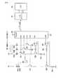
図4は、測距ポイント表示用LED62及びバックライトLED65の駆動回路の構成を示した図である。 FIG. 4 is a diagram showing the configuration of driving circuits for the distance measurement
この場合、測距ポイント表示用LED62は62a、62b、63cの3つで構成されるもので、それぞれBμcom80のポートP01、P02、P03からスイッチングトランジスタQ1、Q2、Q3によって選択的に切り替えられる。そして、これらのLED62a、62b、62cは、それぞれ上記トランジスタQ1、Q2、Q3を介して電流制御用のトランジスタQ5に接続されている。このトランジスタQ5には抵抗R1、R3及びオペアンプ95が接続されており、Bμcom80のポートDA1(D/Aコンバータ)を介して制御されることにより、測距ポイント表示用LED62に流れる電流量が決定され、明るさが制御される。 In this case, the distance measuring
また、バックライトLED65は65a及び65bの2つで構成されており、Bμcom80のポートP04からスイッチングトランジスタQ4が制御されることによって点灯制御される。そして、同様に、バックライトLED65は、トランジスタQ4を介して電流制御用のトランジスタQ6に接続されている。このトランジスタQ6には抵抗R2、R4及びオペアンプ96が接続されており、Bμcom80のポートDA2(D/Aコンバータ)を介して制御されることにより、バックライトLED65に流れる電流量が決定され、明るさが制御される。 Further, the
一方、Bμcom80は、シリアル通信によってLCDドライバ67に種々の情報を送る。そして、このLCDドライバ67がファインダ内LCDパネル64を駆動することによって、Bμcom80から送られた情報が表示される。 On the other hand, the
図5は、ファインダ内の表示例を示したもので、(a)はフォーカシングスクリーン56を撮像した表示画面104の例を示した図、(b)はファインダ内LCDパネル64の表示部107を拡大した図である。 5A and 5B show display examples in the finder. FIG. 5A shows an example of the
図5(a)に示されるように、上記表示画面104は、表示用撮像素子61で撮影された画像の表示部105とファインダ内LCDパネル64に表示された撮影情報の表示部107との合成である。上記表示部105の略中央部には、AF測距を行う際に使用されるAFフレーム106が設けられている。一方、表示部107は、図5(b)に示されるように、種々の撮影情報を表示するための複数のマークより成っている。 As shown in FIG. 5A, the
図5(b)に於いて、110は絞り値を表すマーク、111はシャッタ速度/画質モードを表すマーク、112は合焦マーク、113はフラッシュを表すマーク、114はホワイトバランスを表すマーク、115はAEロックを表すマーク、116は露出補正値を表すマーク、117は測光モードを表すマーク、118は電池残量を表すマーク、そして119は露出モードを表すマークである。 In FIG. 5B, 110 is a mark representing an aperture value, 111 is a mark representing a shutter speed / image quality mode, 112 is a focus mark, 113 is a mark representing flash, 114 is a mark representing white balance, 115 Is a mark representing an AE lock, 116 is a mark representing an exposure correction value, 117 is a mark representing a photometric mode, 118 is a mark representing the remaining battery level, and 119 is a mark representing an exposure mode.
ライブビューモード時は、これらの表示部105及び107に対応した表示が、液晶モニタ36の画面内に画像と撮影情報として表示される。 In the live view mode, displays corresponding to the
図6は、液晶モニタ36に露出情報が表示された際の表示例を示した図である。 FIG. 6 is a view showing a display example when the exposure information is displayed on the
図6に於いて、121は電池残量を表すマーク、122は露出モードを表すマーク、123はシャッタ速度を表すマーク、124は絞り値を表すマーク、125は露出補正値を表すマーク、126はノイズリダクション(ノイズ除去)を表すマーク、127はAEロックを表すマーク、128は測光モードを表すマーク、129は露出補正インジケータ及び露出レベルインジケータを表すマークである。また、131はフラッシュモード等を表すマーク、132はAFフレームを表すマーク、133はドライブモード等を表すマーク、134は画質モード等を表すマーク、135はISO感度を表すマーク、136はホワイトバランスを表すマーク、137はカラー設定等を表すマーク、そして138は残り撮影枚数を表すマークである。 In FIG. 6, 121 is a mark representing the remaining battery level, 122 is a mark representing the exposure mode, 123 is a mark representing the shutter speed, 124 is a mark representing the aperture value, 125 is a mark representing the exposure correction value, and 126 is A mark representing noise reduction (noise removal), 127 a mark representing AE lock, 128 a mark representing photometry mode, and 129 a mark representing an exposure correction indicator and an exposure level indicator.
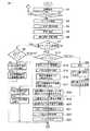
次に、図7乃至図9のフローチャートを参照して、本実施形態に於けるカメラの基本的な撮影動作について説明する。 Next, the basic photographing operation of the camera according to the present embodiment will be described with reference to the flowcharts of FIGS.
カメラ本体30内に電池93が投入されると本ルーチンが開始され、先ずステップS1にてカメラの初期設定がなされる。次いで、ステップS2に於いて、パワースイッチレバー33の操作状態が検出される。ここで、パワースイッチレバー33が操作されて電源がオンされると、続くステップS3にてモードスイッチが検出される。そして、このスイッチ検出により、ステップS4にてモード設定、変更処理がなされる。ステップS5にて測光センサ63及びAFセンサユニット71によって測光及び測距動作が行われると、続くステップS6にて上記ステップS5で得られた値に基づいて測光演算及び測距演算が行われる。 When the
そして、ステップS7に於いて、ファーストレリーズスイッチが離されてから所定時間、この場合8秒が経過したか否かが判定される。ここで、8秒が経過した場合は、ステップS8へ移行してファインダモードであるかライブビューモードであるかが判定される。ライブビューモードである場合は、ステップS9に移行してファインダ内LCDパネル64の表示が消灯されると共に、バックライトLED65も消灯される。次いで、ステップS10にて表示用撮像素子61の自動実行が設定される。その後、ステップS27へ移行する。一方、上記ステップS8にてファインダモードである場合は、ステップS11に移行してファインダ内LCDパネル64の表示が消灯されると共に、バックライトLED65も消灯される。次いで、ステップS12にて液晶モニタ(TFT)に設定情報が表示される。その後、ステップS27へ移行する。 In step S7, it is determined whether or not a predetermined time, in this
上記ステップS7に於いて、ファーストレリーズスイッチが離されていない、または8秒経過していない場合は、ステップS13に移行してファインダモードであるかライブビューモードであるかが判定される。ここで、ライブビューモードである場合は、ステップS14に移行して液晶モニタ(TFT)36に表示用撮像素子61で得られたファインダ画像が表示される。次いで、ステップS15にて、ファインダ内LCDパネル64の表示内容が更新される。ステップS16では、上記表示用撮像素子61の自動実行が設定される。続いて、ステップS17では表示用撮像素子61の感度情報が読み込まれて、ステップS18にてその感度情報から飽和しない範囲のバックライトLED65の光量値が算出される。 If it is determined in step S7 that the first release switch has not been released or 8 seconds have elapsed, the process proceeds to step S13 to determine whether the mode is the finder mode or the live view mode. Here, in the live view mode, the process proceeds to step S14, and the finder image obtained by the display image sensor 61 is displayed on the liquid crystal monitor (TFT) 36. Next, in step S15, the display content of the in-
一方、上記ステップS13にてファインダモードである場合は、ステップS24へ移行して、再度測光センサ63による測光が行われる。次いで、ステップS25では液晶モニタ(TFT)36には、上記ステップS24での測光値に基づいて、露出値の演算が行われ、その結果の露出情報が表示される。更に、ステップS26では、上記ステップS24で得られた測光値からバックライトLED65の光量値が演算される。 On the other hand, if the viewfinder mode is set in step S13, the process proceeds to step S24, and the photometry by the
ステップS19では、上記ステップS18またはS26で算出された光量値から、バックライトLED65の電流が演算される。そして、ステップS20では、上記ステップS19で得られたバックライトLED65の電流から出力電圧が演算される。すると、続くステップS21にて、Bμcom80のD/Aポート(DA2)に設定電圧が出力される。次いで、ステップS22にて、ファインダ内LCD64の表示が更新される。そして、ステップS23にてバックライト65が点灯される。 In step S19, the current of the
次に、ステップS27に於いて、レリーズ釦31の第1レリーズ(1R)スイッチの状態が検出される。ここで、第1レリーズスイッチがオフ状態であれば上記ステップS2へ移行する。一方、第1レリーズスイッチがオンされていれば、ステップS28へ移行して、ファインダモードであるかライブビューモードであるかが判定される。ここで、ライブビューモードである場合は、ステップS29に移行して、表示用撮像素子61で得られた画像の処理及び液晶モニタ36への表示が行われる。一方、ファインダモードの場合は、ステップS30に移行して、液晶モニタ36の表示が消灯される。 Next, in step S27, the state of the first release (1R) switch of the release button 31 is detected. Here, if the first release switch is in the OFF state, the process proceeds to step S2. On the other hand, if the first release switch is turned on, the process proceeds to step S28 to determine whether the mode is the finder mode or the live view mode. Here, in the live view mode, the process proceeds to step
ステップS31では、測光センサ63及びAFセンサユニット71によって測光及び測距動作が行われ、続くステップS32にて上記ステップS31で得られた値に基づいて測光演算及び測距演算が行われる。そして、ステップS33に於いて、再度ファインダモードであるかライブビューモードであるかが判定される。その結果、ライブビューモードである場合は、ステップS34に移行して、ファインダ内LCDパネル64による表示の更新とバックライトLED65の点灯が行われる。次いで、ステップS35にて液晶モニタ36にファインダ画像と露出情報が合成表示された後、ステップS37へ移行する。上記ステップS33にてファインダモードであると判定された場合は、ステップS36に移行してファインダ内LCDパネル64の表示が更新されると共に、バックライトLED65が点灯される。その後、ステップS37へ移行する。 In step S31, photometry and distance measurement operations are performed by the
ステップS37では、撮影レンズ11が合焦範囲内であるか否かが判定される。その結果、まだ合焦範囲にない場合は、ステップS38に移行して撮影レンズ11がレンズ駆動機構13等により駆動され、その後上記ステップS27に移行して上述した処理動作が繰り返される。一方、上記ステップS37にて合焦範囲内である場合は、ステップS39に移行してファインダ内LCDパネル64に合焦した旨の合焦マーク112が表示される。次いで、ステップS40にて表示用撮像素子61の感度の変更が禁止される。そして、ステップS41では、表示用撮像素子61の感度情報が読み出される。 In step S37, it is determined whether or not the taking
次に、ステップS42では、上記ステップS41で読み出された感度情報から、飽和しない範囲の測距ポイント表示用LED62の光量値が算出される。そして、ステップS43では、上記ステップS42で得られた光量値から、測距ポイント表示用LED62に流れる電流が算出される。更に、ステップS44では、上記ステップS43で得られたLED電流から、Bμcom80の出力電圧が演算される。ステップS45では、Bμcom80のD/Aポートから設定電圧が出力される。 Next, in step S42, the light amount value of the distance measuring
そして、ステップS46では、合焦ポイントに、測距ポイント表示用LED62a〜62cのうち該当するLEDが所定時間点灯される。続いて、ステップS47では、表示用撮像素子61の感度変更禁止が解除される。これは、LEDが点灯されると、その点灯された光によってフィードバックがかかって画面が暗くなることを防止するためである。この感度変更禁止が解除されることにより、被写界輝度に応じて画面が適正露出に合わせられるようになる。 In step S46, the LED corresponding to the focusing
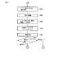
次いで、ステップS48及びS49にて第1レリーズスイッチ及び第2レリーズスイッチの状態が検出される。ここでは、第1レリーズスイッチ及び第2レリーズスイッチがオンになるまで待機する。その結果、第1レリーズスイッチがオフになれば上記ステップS2に移行する。そして、第1レリーズスイッチ及び第2レリーズスイッチが共にオンになれば、ステップS50に移行してファインダ内LCDパネル64の表示が消灯される。また、それと共にバックライトLED65も消灯される。 Next, in steps S48 and S49, the states of the first release switch and the second release switch are detected. Here, the process waits until the first release switch and the second release switch are turned on. As a result, if the first release switch is turned off, the process proceeds to step S2. If both the first release switch and the second release switch are turned on, the process proceeds to step S50 and the display on the
ステップS51では、第1反射ミラー51が撮影光路より退避され、絞り込みがなされて撮影準備が行われる。続いて、ステップS52にて、撮影用撮像素子67による撮像が行われる。そして、撮像終了後は、ステップS53にて第1反射ミラー51が撮影光路内に復帰され、絞り12が開放され、撮像された画像が撮影用撮像素子67からインターフェイス回路81を介して画像処理コントローラ82に転送される。ステップS54では、この画像処理コントローラ82にて撮像された画像の処理が行われ、その画像が液晶モニタ36に表示される。次いで、ステップS55にて記録メディア85に画像データが記録される。この後、ステップS56に於いて連写モードであるか単写モードであるかが判定される。その結果、単写モードであれば上記ステップS2へ移行し、連写モードであれば上記ステップS27へ移行して、それぞれ以降の処理が繰り返される。 In step S51, the first reflecting
このように、撮影用撮像素子の感度情報からLEDの光量を調整することができるようにしたので、撮影情報等の表示が見え難くなることなく、使い勝手のよい高品位のライブビュー表示機能を有するファインダ装置及びカメラを提供することができる。 As described above, since the light quantity of the LED can be adjusted from the sensitivity information of the image sensor for photographing, it has a high-quality live view display function that is easy to use without making the display of photographing information or the like difficult to see. A finder device and a camera can be provided.
以上、本発明の実施形態について説明したが、本発明は上述した実施形態以外にも、本発明の要旨を逸脱しない範囲で種々の変形実施が可能である。 As mentioned above, although embodiment of this invention was described, in the range which does not deviate from the summary of this invention other than embodiment mentioned above, this invention can be variously modified.
10…レンズ鏡筒、11…撮影レンズ、12…絞り、13…レンズ駆動機構、14…絞り駆動機構、15…レンズ制御用マイクロコンピュータ(Lμcom)、20…通信コネクタ、30…カメラ本体、31…レリーズ釦、32…モードダイヤル、33…パワースイッチレバー、34…コントロールダイヤル、36…液晶モニタ、43…ファインダ、50…ファインダ光学系、51…第1反射ミラー、52…第2反射ミラー、53…第3反射ミラー、54…第4反射ミラー、56…フォーカシングスクリーン、57…接眼レンズ、61…表示用撮像素子、62、62a、62b、62c…測距ポイント表示用LED、63…測光センサ、64…ファインダ(F)内LCDパネル、65、65a、65b…バックライトLED、66…シャッタ、67…撮影用表示素子、71…AFセンサユニット、72…AFセンサ駆動回路、73…ミラー駆動機構、75…シャッタチャージ機構、76…シャッタ制御回路、81…インターフェイス回路、82…画像処理コントローラ、83…SDRAM、84…FlashMemory、85…不揮発性メモリ(EEPROM)、90…動作表示用LCD、91…カメラ操作スイッチ(SW)、92…電源回路。 DESCRIPTION OF
Claims (11)
Translated fromJapanese上記スクリーンマット上の被写体像を含むファインダ画像を繰り返し取得する撮像手段と、
上記撮像手段で取得された画像データを表示する画像表示手段と、
上記ファインダ内に配置された発光表示手段と、
を具備するファインダ装置に於いて、
上記発光表示手段は、発光表示動作を行った際に上記撮像手段の受光レベルが飽和しないように、その発光量を調整可能であることを特徴とするファインダ装置。A screen mat which is arranged in the viewfinder optical path and forms a subject image;
Imaging means for repeatedly obtaining a finder image including a subject image on the screen mat;
Image display means for displaying the image data acquired by the imaging means;
Light emitting display means disposed in the viewfinder;
In a finder apparatus comprising:
The finder device, wherein the light emission display means is capable of adjusting a light emission amount so that a light reception level of the imaging means is not saturated when a light emission display operation is performed.
上記スクリーンマット上の被写体像を含むファインダ画像を繰り返し取得する撮像手段と、
上記撮像手段で取得された画像データを表示する画像表示手段と、
上記ファインダ光路内に配置されて情報表示を行う発光表示手段と、
上記スクリーンマット上の被写体像及び上記発光表示手段により表示された情報を観察するためのファインダ光学系と、
上記発光表示手段の発光表示動作を行った際に上記撮像手段の受光レベルが飽和しないように、その発光量を制御する制御手段と、
を具備することを特徴とするカメラ。A screen mat which is arranged in the viewfinder optical path and forms a subject image;
Imaging means for repeatedly obtaining a finder image including a subject image on the screen mat;
Image display means for displaying the image data acquired by the imaging means;
Light emitting display means arranged in the finder optical path for displaying information;
A viewfinder optical system for observing the subject image on the screen mat and the information displayed by the light emitting display means;
Control means for controlling the light emission amount so that the light receiving level of the imaging means is not saturated when the light emission display operation of the light emission display means is performed;
A camera comprising:
Priority Applications (3)
| Application Number | Priority Date | Filing Date | Title |
|---|---|---|---|
| JP2005168267AJP2006345172A (en) | 2005-06-08 | 2005-06-08 | Viewfinder device and camera |
| US11/443,672US7583892B2 (en) | 2005-06-08 | 2006-05-31 | Finder device and camera |
| CNB2006100879599ACN100510937C (en) | 2005-06-08 | 2006-06-08 | Finder device and camera |
Applications Claiming Priority (1)
| Application Number | Priority Date | Filing Date | Title |
|---|---|---|---|
| JP2005168267AJP2006345172A (en) | 2005-06-08 | 2005-06-08 | Viewfinder device and camera |
Publications (1)
| Publication Number | Publication Date |
|---|---|
| JP2006345172Atrue JP2006345172A (en) | 2006-12-21 |
Family
ID=37509908
Family Applications (1)
| Application Number | Title | Priority Date | Filing Date |
|---|---|---|---|
| JP2005168267APendingJP2006345172A (en) | 2005-06-08 | 2005-06-08 | Viewfinder device and camera |
Country Status (3)
| Country | Link |
|---|---|
| US (1) | US7583892B2 (en) |
| JP (1) | JP2006345172A (en) |
| CN (1) | CN100510937C (en) |
Families Citing this family (30)
| Publication number | Priority date | Publication date | Assignee | Title |
|---|---|---|---|---|
| JP4730553B2 (en)* | 2006-07-25 | 2011-07-20 | 富士フイルム株式会社 | Imaging apparatus and exposure control method |
| JP2008199088A (en)* | 2007-02-08 | 2008-08-28 | Fujifilm Corp | Imaging device |
| KR101467928B1 (en)* | 2007-07-23 | 2014-12-04 | 삼성전자주식회사 | A / V device outputting device information and method of outputting device information |
| JP2009047956A (en)* | 2007-08-21 | 2009-03-05 | Sony Corp | Imaging apparatus |
| JP5310266B2 (en)* | 2009-05-29 | 2013-10-09 | セイコーエプソン株式会社 | Projector and control method thereof |
| WO2010029767A1 (en)* | 2008-09-11 | 2010-03-18 | パナソニック株式会社 | Imaging device |
| JP5120372B2 (en)* | 2009-12-25 | 2013-01-16 | 株式会社ニコン | Imaging device |
| JP5457217B2 (en)* | 2010-02-02 | 2014-04-02 | オリンパスイメージング株式会社 | camera |
| JP2011164536A (en)* | 2010-02-15 | 2011-08-25 | Seiko Epson Corp | Image display device, brightness control method, and brightness control program |
| JP2013026744A (en)* | 2011-07-19 | 2013-02-04 | Sanyo Electric Co Ltd | Electronic camera |
| JP5578749B2 (en)* | 2011-10-19 | 2014-08-27 | 富士フイルム株式会社 | Variable magnification finder device and display information brightness changing method |
| JP2013128240A (en)* | 2011-12-19 | 2013-06-27 | Sanyo Electric Co Ltd | Electronic camera |
| US10009536B2 (en) | 2016-06-12 | 2018-06-26 | Apple Inc. | Applying a simulated optical effect based on data received from multiple camera sensors |
| DK180859B1 (en) | 2017-06-04 | 2022-05-23 | Apple Inc | USER INTERFACE CAMERA EFFECTS |
| US11112964B2 (en) | 2018-02-09 | 2021-09-07 | Apple Inc. | Media capture lock affordance for graphical user interface |
| US11722764B2 (en) | 2018-05-07 | 2023-08-08 | Apple Inc. | Creative camera |
| US10897577B2 (en)* | 2018-06-26 | 2021-01-19 | Canon Kabushiki Kaisha | Image capturing system, image capturing apparatus, illumination apparatus, and control method |
| DK201870623A1 (en) | 2018-09-11 | 2020-04-15 | Apple Inc. | User interfaces for simulated depth effects |
| US11321857B2 (en) | 2018-09-28 | 2022-05-03 | Apple Inc. | Displaying and editing images with depth information |
| US11128792B2 (en) | 2018-09-28 | 2021-09-21 | Apple Inc. | Capturing and displaying images with multiple focal planes |
| WO2020184230A1 (en)* | 2019-03-12 | 2020-09-17 | キヤノン株式会社 | Imaging device, information processing device, and image processing system |
| US11706521B2 (en) | 2019-05-06 | 2023-07-18 | Apple Inc. | User interfaces for capturing and managing visual media |
| US10645294B1 (en) | 2019-05-06 | 2020-05-05 | Apple Inc. | User interfaces for capturing and managing visual media |
| US11770601B2 (en) | 2019-05-06 | 2023-09-26 | Apple Inc. | User interfaces for capturing and managing visual media |
| US11054973B1 (en) | 2020-06-01 | 2021-07-06 | Apple Inc. | User interfaces for managing media |
| US11212449B1 (en) | 2020-09-25 | 2021-12-28 | Apple Inc. | User interfaces for media capture and management |
| US11778339B2 (en) | 2021-04-30 | 2023-10-03 | Apple Inc. | User interfaces for altering visual media |
| US11539876B2 (en) | 2021-04-30 | 2022-12-27 | Apple Inc. | User interfaces for altering visual media |
| US12112024B2 (en) | 2021-06-01 | 2024-10-08 | Apple Inc. | User interfaces for managing media styles |
| US20240373121A1 (en) | 2023-05-05 | 2024-11-07 | Apple Inc. | User interfaces for controlling media capture settings |
Citations (2)
| Publication number | Priority date | Publication date | Assignee | Title |
|---|---|---|---|---|
| JPS62141862A (en)* | 1985-12-16 | 1987-06-25 | Nippon Kogaku Kk <Nikon> | Finder device for single-lens reflex camera |
| JP2001305637A (en)* | 2000-04-26 | 2001-11-02 | Kyocera Corp | Camera with electronic viewfinder |
Family Cites Families (17)
| Publication number | Priority date | Publication date | Assignee | Title |
|---|---|---|---|---|
| JPS5699332A (en)* | 1980-01-10 | 1981-08-10 | Canon Inc | Information mark display device |
| US4704022A (en) | 1985-09-12 | 1987-11-03 | Nippon Kogaku K. K. | Video finder for single-lens reflex camera |
| DE4330265B4 (en)* | 1992-09-07 | 2004-07-29 | Canon K.K. | Device for detecting the visual axis of an eye of a person operating an optical device |
| JPH10142685A (en) | 1996-11-14 | 1998-05-29 | Olympus Optical Co Ltd | Silver salt photographic and electronic image pickup camera |
| US6639626B1 (en) | 1998-06-18 | 2003-10-28 | Minolta Co., Ltd. | Photographing apparatus with two image sensors of different size |
| JP2000013661A (en) | 1998-06-18 | 2000-01-14 | Minolta Co Ltd | Digital camera |
| JP2000165730A (en) | 1998-11-27 | 2000-06-16 | Olympus Optical Co Ltd | Electronic camera |
| JP2001078069A (en) | 1999-09-06 | 2001-03-23 | Canon Inc | Imaging method and apparatus, and storage medium |
| JP2001125173A (en) | 1999-10-26 | 2001-05-11 | Minolta Co Ltd | Digital camera |
| JP4605846B2 (en) | 2000-02-08 | 2011-01-05 | 日本電産コパル株式会社 | Electronic camera |
| JP4667590B2 (en) | 2000-12-12 | 2011-04-13 | 日本電産コパル株式会社 | Digital single-lens reflex camera |
| JP4043198B2 (en) | 2001-03-23 | 2008-02-06 | 株式会社リコー | Electronic camera |
| JP4646442B2 (en) | 2001-06-05 | 2011-03-09 | キヤノン株式会社 | Digital single-lens reflex camera, control method therefor, and storage medium |
| US6816676B2 (en)* | 2002-04-19 | 2004-11-09 | Hewlett-Packard Development Company, L.P. | Adaptive control of LCD display utilizing imaging sensor measurements |
| JP2005010643A (en) | 2003-06-20 | 2005-01-13 | Kyocera Corp | Digital single-lens reflex camera |
| US7924307B2 (en)* | 2003-08-14 | 2011-04-12 | Carl Zeiss Ag | Optical viewing system and method for operating the same |
| JP2006011025A (en) | 2004-06-25 | 2006-01-12 | Nikon Corp | Electronic camera |
- 2005
- 2005-06-08JPJP2005168267Apatent/JP2006345172A/enactivePending
- 2006
- 2006-05-31USUS11/443,672patent/US7583892B2/ennot_activeExpired - Fee Related
- 2006-06-08CNCNB2006100879599Apatent/CN100510937C/ennot_activeExpired - Fee Related
Patent Citations (2)
| Publication number | Priority date | Publication date | Assignee | Title |
|---|---|---|---|---|
| JPS62141862A (en)* | 1985-12-16 | 1987-06-25 | Nippon Kogaku Kk <Nikon> | Finder device for single-lens reflex camera |
| JP2001305637A (en)* | 2000-04-26 | 2001-11-02 | Kyocera Corp | Camera with electronic viewfinder |
Also Published As
| Publication number | Publication date |
|---|---|
| CN100510937C (en) | 2009-07-08 |
| US7583892B2 (en) | 2009-09-01 |
| CN1877437A (en) | 2006-12-13 |
| US20060280495A1 (en) | 2006-12-14 |
Similar Documents
| Publication | Publication Date | Title |
|---|---|---|
| CN100510937C (en) | Finder device and camera | |
| US7872684B2 (en) | Camera capable of correcting information for focusing control, using information stored in storage section of mounted lens apparatus | |
| JP2005181356A5 (en) | ||
| US8559808B2 (en) | Imaging apparatus | |
| JP2008211630A (en) | Imaging device | |
| US7609960B2 (en) | Finder device and camera | |
| US20070172226A1 (en) | Digital single-lens reflex camera | |
| JP2007006357A (en) | Digital camera and digital single-lens reflex camera | |
| JP5333888B2 (en) | Imaging apparatus and program thereof | |
| JP2012185289A (en) | Camera system, lens barrel, and camera body | |
| JP2010224290A (en) | camera | |
| JP2007006097A (en) | Camera | |
| JP2007248852A (en) | Focusing device for camera | |
| JP2007060131A (en) | Camera with live view display function | |
| JP2004212892A (en) | Imaging device | |
| JP2009282378A (en) | Imaging apparatus and imaging apparatus body | |
| JP2007072286A (en) | Camera capable of performing live view display | |
| JP4524208B2 (en) | Digital camera | |
| JP4468784B2 (en) | Digital single-lens reflex camera | |
| JP2005321832A (en) | Image display method in camera | |
| JP2007011070A (en) | Digital single-lens reflex camera | |
| JP2007049363A (en) | Camera | |
| JP2009303113A (en) | Electronic camera | |
| JP2007202024A (en) | Imaging device | |
| JP2007101860A (en) | Imaging device |
Legal Events
| Date | Code | Title | Description |
|---|---|---|---|
| A621 | Written request for application examination | Free format text:JAPANESE INTERMEDIATE CODE: A621 Effective date:20080225 | |
| A977 | Report on retrieval | Free format text:JAPANESE INTERMEDIATE CODE: A971007 Effective date:20100319 | |
| A131 | Notification of reasons for refusal | Free format text:JAPANESE INTERMEDIATE CODE: A131 Effective date:20100427 | |
| A02 | Decision of refusal | Free format text:JAPANESE INTERMEDIATE CODE: A02 Effective date:20100831 |