JP2006344409A - Light fixture, and display device provided with the same - Google Patents
Light fixture, and display device provided with the sameDownload PDFInfo
- Publication number
- JP2006344409A JP2006344409AJP2005166954AJP2005166954AJP2006344409AJP 2006344409 AJP2006344409 AJP 2006344409AJP 2005166954 AJP2005166954 AJP 2005166954AJP 2005166954 AJP2005166954 AJP 2005166954AJP 2006344409 AJP2006344409 AJP 2006344409A
- Authority
- JP
- Japan
- Prior art keywords
- light
- light source
- control plate
- concentric
- prism
- Prior art date
- Legal status (The legal status is an assumption and is not a legal conclusion. Google has not performed a legal analysis and makes no representation as to the accuracy of the status listed.)
- Pending
Links
- 238000005286illuminationMethods0.000claimsdescription35
- 230000005540biological transmissionEffects0.000claimsdescription22
- OAICVXFJPJFONN-UHFFFAOYSA-NPhosphorusChemical compound[P]OAICVXFJPJFONN-UHFFFAOYSA-N0.000claimsdescription6
- 239000000463materialSubstances0.000claimsdescription5
- 239000000758substrateSubstances0.000claimsdescription4
- 239000002245particleSubstances0.000claimsdescription2
- 238000009826distributionMethods0.000abstractdescription26
- 239000004973liquid crystal related substanceSubstances0.000description28
- 230000002093peripheral effectEffects0.000description21
- 238000002834transmittanceMethods0.000description14
- 239000011347resinSubstances0.000description10
- 229920005989resinPolymers0.000description10
- 238000009792diffusion processMethods0.000description8
- 230000005855radiationEffects0.000description5
- 238000000151depositionMethods0.000description4
- 239000002184metalSubstances0.000description4
- 229910052751metalInorganic materials0.000description4
- 229910052709silverInorganic materials0.000description4
- 238000004519manufacturing processMethods0.000description3
- 239000011159matrix materialSubstances0.000description3
- OKTJSMMVPCPJKN-UHFFFAOYSA-NCarbonChemical compound[C]OKTJSMMVPCPJKN-UHFFFAOYSA-N0.000description2
- 229910052799carbonInorganic materials0.000description2
- 238000006243chemical reactionMethods0.000description2
- 239000011248coating agentSubstances0.000description2
- 238000000576coating methodMethods0.000description2
- 238000001465metallisationMethods0.000description2
- 238000005457optimizationMethods0.000description2
- 239000000049pigmentSubstances0.000description2
- 238000007740vapor depositionMethods0.000description2
- 239000012463white pigmentSubstances0.000description2
- 230000007423decreaseEffects0.000description1
- 230000000694effectsEffects0.000description1
- 230000001678irradiating effectEffects0.000description1
- 238000000465mouldingMethods0.000description1
- 239000000126substanceSubstances0.000description1
Images


Landscapes
- Liquid Crystal (AREA)
- Planar Illumination Modules (AREA)
Abstract
Description
Translated fromJapanese本発明は、携帯情報機器や携帯電話や液晶テレビなどに用いられる液晶表示装置の液晶素子を照明する照明装置に関する。 The present invention relates to an illuminating device that illuminates a liquid crystal element of a liquid crystal display device used in a portable information device, a mobile phone, a liquid crystal television, and the like.
近年の携帯電話やモバイルコンピュータなどに用いられる表示装置には、高精彩カラー画像が少ない消費電力で得られる液晶表示装置が多く用いられている。これらの液晶表示装置に用いられる液晶素子を照明するため、高輝度の白色LEDを用いた光源が照明装置用光源として用いられるようになっている。これらの表示装置の照明に用いられている白色LEDは、青色LEDの発光面の直前に黄色蛍光体を分散させた樹脂を配して、黄色光と青色光とを混色させて白色光を得る構造としたものが良く知られている。一方、LED光源を用いたバックライトは中型・大型液晶表示装置にも用いられつつある。LED光源を用いたバックライトとしては、小型液晶表示装置と同様にバックライトの側面から光を導入するサイドライト型バックライトが多用されてきたが、照明画面が大きいために用いられるLED光源の数は数百個にもなるものが出現している。このように大量のLED光源を用いないで中型・大型液晶表示素子を照明するために、これら中型・大型液晶表示素子の背面から直接照明光を照射する、いわゆる直下型照明装置が考案されている。この直下型照明装置は、1つのLED光源でより広い領域を照射するために、LED光源の近傍真上に光反射構造を設けて実質的に光照射領域を広げる工夫をしたものが開示されている(例えば、特許文献1を参照)。
しかしながら、従来の直下型照明装置は、非自発光素子である液晶表示素子に照射される光の照射方向が十分制御されていないために液晶表示装置の視角特性と輝度分布が良くないという課題を有していた。また、光反射構造体をLED光源の近傍真上に設けた場合には、光反射構造体がLED光源の発光面に近過ぎるため、十分に照射領域を広げることができず、LED光源の数を減らすことができないという課題を有していた。 However, the conventional direct illumination device has a problem that the viewing angle characteristic and the luminance distribution of the liquid crystal display device are not good because the irradiation direction of the light irradiated to the liquid crystal display element which is a non-self-luminous element is not sufficiently controlled. Had. In addition, when the light reflecting structure is provided immediately above the LED light source, the light reflecting structure is too close to the light emitting surface of the LED light source, so that the irradiation area cannot be sufficiently expanded, and the number of LED light sources There was a problem that it was not possible to reduce.
本発明は、より少ないLED光源を用いて、視角特性と輝度分布が良い直下型照明装置を提供することを目的とする。 An object of the present invention is to provide a direct illumination device having a good viewing angle characteristic and luminance distribution using fewer LED light sources.
本発明の液晶表示装置の照明装置は、回路基板上に配置された複数のLED光源と、これらLED光源側に配した光制御板とからなり、各LED光源1つ1つに対して各LED光源からの出射光の照射方向を制御するためのプリズム構造が光制御板上に形成された構造である。このプリズム構造は光制御板の裏面に形成されたLED光源からの照射光の中心を共通の中心として有する同心円凸状プリズム群とするか、もしくは光制御板の光照射面に形成されたLED光源からの照射光の中心を共通の中心として有する同心円凹状プリズム群とした。このような構成によって、LED光源からの光を目的の方向に指向性を持たせて照射することが可能となり、その結果、表示装置の視角特性と輝度分布を向上させることができる。 The illuminating device for a liquid crystal display device of the present invention comprises a plurality of LED light sources arranged on a circuit board and a light control plate arranged on the LED light source side, and each LED light source is provided with each LED. The prism structure for controlling the irradiation direction of the light emitted from the light source is formed on the light control plate. This prism structure is a concentric convex prism group having the center of the irradiation light from the LED light source formed on the back surface of the light control plate as a common center, or the LED light source formed on the light irradiation surface of the light control plate A concentric concave prism group having the center of the irradiation light from the common center. With such a configuration, it becomes possible to irradiate the light from the LED light source with directivity in a target direction, and as a result, it is possible to improve the viewing angle characteristic and the luminance distribution of the display device.
同心円凸プリズム群の光制御板の厚み方向の断面を、LED光源の光が所定の角度範囲に入射する内側同心円面と、光制御板内部に入射した光が光制御板の光出射面に対して略垂直反射されるように配された外側同心円面で形成する三角形状で構成した。あるいは、同心円凹プリズム群の光制御板の厚み方向の断面を、光制御板の内部に入射した光が光制御板の光出射面から所定の角度範囲に出射するように配された内側同心円面と略垂直な面を持った外側同心円面で構成する三角形状とした。このような構成によって、損失を最小にして所定の出射角を持った光を光制御板の光出射面から出射させることが可能となり、視角特性に係わる上記課題を解決することができた。 A cross section of the light control plate in the thickness direction of the concentric convex prism group is shown with respect to the inner concentric surface where the light from the LED light source enters the predetermined angle range, and the light incident inside the light control plate with respect to the light exit surface of the light control plate. And formed in a triangular shape formed by outer concentric circular surfaces arranged so as to be substantially vertically reflected. Alternatively, the cross-section in the thickness direction of the light control plate of the concentric concave prism group is an inner concentric surface arranged so that light incident on the light control plate is emitted within a predetermined angle range from the light emission surface of the light control plate. And a triangular shape composed of an outer concentric surface having a substantially vertical surface. With such a configuration, it is possible to emit light having a predetermined emission angle with a minimum loss from the light emission surface of the light control plate, and to solve the above-mentioned problems related to viewing angle characteristics.
また、同心円凸プリズム群の光制御板の厚み方向の断面または同心円凹プリズム群の光制御板の厚み方向の断面を形成する三角形の高さをLED光源から遠ざかるに従って高くして、光制御板からの出射光強度が一様になるようにした。これにより、輝度分布が一様な照明装置が実現できる。さらに、LED光源と光制御板との間に光拡散板を設けることによって、より均一な輝度分布が実現できる。 Further, the height of the triangle that forms the cross section in the thickness direction of the light control plate of the concentric circular convex prism group or the cross section in the thickness direction of the light control plate of the concentric circular concave prism group is increased as the distance from the LED light source is increased. The intensity of the emitted light was made uniform. Thereby, the illuminating device with uniform luminance distribution is realizable. Furthermore, a more uniform luminance distribution can be realized by providing a light diffusion plate between the LED light source and the light control plate.
そして、光制御板のLED光源に対する真上の位置に、部分透過鏡を配した。さらにまた、光制御板と回路基板との間隙に光反射層を配した。このような構成によって、光制御板から出射される照明光の輝度分布を一様にすることができると同時に、LED光源の光の利用効率を向上させることができた。その結果、使用するLED光源の個数を減らすことが可能となった。 A partial transmission mirror was disposed at a position directly above the LED light source of the light control plate. Furthermore, a light reflecting layer is disposed in the gap between the light control board and the circuit board. With such a configuration, the luminance distribution of the illumination light emitted from the light control plate can be made uniform, and at the same time, the light use efficiency of the LED light source can be improved. As a result, the number of LED light sources to be used can be reduced.
さらにまた、回路基板上に実装されているLED光源をモールドする透明樹脂として非通水性材料を用い、その非通水性材料中に青色光を緑色光および赤色光に波長変換する蛍光体粒子を混合して、白色LED光源とした。透明樹脂のモールド形状を略球形表面を有するドーム型とすることによって、光利用効率を向上させることができ、より高輝度な照明装置とすることが可能となった。 Furthermore, a non-water-permeable material is used as a transparent resin for molding the LED light source mounted on the circuit board, and phosphor particles that convert blue light into green light and red light are mixed in the non-water-permeable material. Thus, a white LED light source was obtained. By making the mold shape of the transparent resin into a dome shape having a substantially spherical surface, it is possible to improve the light utilization efficiency and to obtain a lighting device with higher brightness.
そして、上述した構成の照明装置を液晶表示素子の背面に配することによって、高輝度で高精彩な液晶表示装置が実現できた。そして、照明装置と液晶表示素子の間に拡散板を設けることによって、さらに輝度分布を向上させることが可能となる。また、微細なプリズムが並行に配列したプリズムシートを配することによって出射光の趣向性を改善することが可能となりさらに高輝度の液晶表示装置とすることができた。 A high-brightness and high-definition liquid crystal display device can be realized by arranging the illumination device having the above-described configuration on the back surface of the liquid crystal display element. Then, by providing a diffusion plate between the lighting device and the liquid crystal display element, the luminance distribution can be further improved. Further, by arranging a prism sheet in which fine prisms are arranged in parallel, the preference of the emitted light can be improved, and a liquid crystal display device with higher luminance can be obtained.
本発明の照明装置は、回路基板上に配列されたLED光源からの光を光制御板によって直接被照明物に照射するために、回路基板の大きさを変えるだけで任意の大きさの被照明物を照明することができる。さらに、LED光源の数を減らすことが可能になるので、液晶表示装置などの製造価格と消費電力を低減できるという効果を有する。 The illumination device of the present invention irradiates an object to be illuminated with light of an arbitrary size simply by changing the size of the circuit board in order to directly irradiate the object to be illuminated with the light control plate with the light from the LED light sources arranged on the circuit board Objects can be illuminated. Furthermore, since the number of LED light sources can be reduced, the manufacturing price and power consumption of a liquid crystal display device and the like can be reduced.
本発明の照明装置の構成を図1に模式的に示す。本発明による照明装置は、図1に示すように、複数の点光源1が配置された基板2と、点光源を介してこの基板と対向するように配置された光制御板3を備えており、この光制御板上には点光源からの出射光の照射方向を制御するためのプリズム体4が一つ一つの点光源に対応して設けられている。 The structure of the illumination device of the present invention is schematically shown in FIG. As shown in FIG. 1, the illuminating device according to the present invention includes a
ここで、点光源からの照射光の中心を共通の中心とする同心円凸状プリズムを光制御板の光入射面に設けて、これをプリズム体とすることができる。このとき、同心円凸状プリズムの断面を、点光源からの光が所定の角度範囲に入射する内側同心円面と、光制御板内部に入射した光が当該光制御板の光出射面に対して略垂直反射されるように配された外側同心円面で形成した三角形状とする。さらに、同心円凸状プリズムの断面を形成する三角形の高さが点光源から遠ざかるに従って高くなるようにしてもよい。 Here, a concentric convex prism having the center of the irradiation light from the point light source as a common center is provided on the light incident surface of the light control plate, and this can be used as a prism body. At this time, the cross-section of the concentric convex prism is roughly divided into the inner concentric surface where the light from the point light source enters the predetermined angular range, and the light incident inside the light control plate with respect to the light exit surface of the light control plate. A triangular shape formed by outer concentric circular surfaces arranged to be vertically reflected. Further, the height of the triangle forming the cross section of the concentric convex prism may be increased as the distance from the point light source is increased.
あるいは、点光源からの照射光の中心を共通の中心とする同心円凹状プリズムを光制御板の光照射面に設けて、これをプリズム体とすることができる。このとき、同心円凹状プリズムの断面を、点光源からの光が所定の角度範囲に入射する内側同心円面と、光制御板内部に入射した光が当該光制御板の光出射面に対して略垂直反射されるように配された外側同心円面で形成した三角形状とする。さらに、同心円凹状プリズムの断面を形成する三角形の深さが点光源から遠ざかるほど深くなるようにしてもよい。 Alternatively, a concentric concave prism having the center of the irradiation light from the point light source as a common center may be provided on the light irradiation surface of the light control plate to form a prism body. At this time, the cross section of the concentric concave prism is divided into an inner concentric surface where light from a point light source is incident within a predetermined angle range, and light incident inside the light control plate is substantially perpendicular to the light exit surface of the light control plate. A triangular shape formed by outer concentric circular surfaces arranged to be reflected. Further, the depth of the triangle forming the cross section of the concentric concave prism may be deepened as the distance from the point light source is increased.
また、点光源と光制御板の間に光拡散板を設けることとした。また、光制御板の光出射面の点光源の真上の位置に部分透過鏡を設けることとした。また、光制御板と回路基板の間に、点光源と対応する部位に開口を有する光反射層を設けることとした。 In addition, a light diffusion plate is provided between the point light source and the light control plate. In addition, a partial transmission mirror is provided at a position directly above the point light source on the light exit surface of the light control plate. Further, a light reflection layer having an opening at a portion corresponding to the point light source is provided between the light control plate and the circuit board.
本発明による表示装置は、上述したいずれかの構成の照明装置を用いて、非自発光型の表示素子を背後から照明する構成であるため、従来より明るい表示が可能になる。あるいは、少ない光源数で従来と同等の明るさが実現できる。 Since the display device according to the present invention is configured to illuminate a non-self-luminous display element from behind using the illumination device having any one of the above-described configurations, a brighter display than before is possible. Or brightness equivalent to the conventional one can be realized with a small number of light sources.
以下に点光源としてLED光源を用いた例を、図面を用いて具体的に説明する。 Hereinafter, an example in which an LED light source is used as a point light source will be specifically described with reference to the drawings.
図1は本実施例の照明装置の構成を模式的に示す斜視図である。LED光源1は回路基板2上に行列状に配列されている。図示されていないが、回路基板2には各LED光源1に電力を供給する配線が形成されており、これらの配線を外部の制御回路や電源に接続するためのコネクタも設けられている。LED光源1は回路基板2に形成された配線にワイヤーボンディングや導電ペーストなどを用いて接続されている。また、各LED光源1は透明樹脂でポッティングされている。 FIG. 1 is a perspective view schematically showing the configuration of the illumination device of this embodiment. The
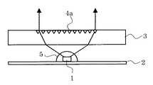
一方、光制御板3は透明基材で形成されており、各LED光源1に対応する位置の真上に各LED光源1からの光を所定の角度範囲に均一に照射するための同心円プリズム4が形成されている。この同心円プリズム4を光制御板3の光入射面、すなわちLED光源1と対向する面側に設ける場合は同心円凸プリズム群を形成し、光出射面側に設ける場合は同心円凹プリズム群を形成する。 On the other hand, the
光制御板3の光出射面側に同心円凹プリズム群を形成した場合、LED光源近傍を拡大した部分断面図を図2に模式的に示す。この同心円凹プリズム群4aの同心円の中心はLED光源1のほぼ真上に位置するように配置されている。また、図を見やすくするために省略されているが、同心円凹プリズム群4aにすぐに隣接して隣接したLED光源からの光を制御する他の同心円凹プリズム群が形成されている。同心円凹プリズム群4aの最外円の径はLED光源の輻射分布と光制御板3の板厚およびLED光源1と光制御板3との間隔によって決定される。図2の矢印で示されているようにLED光源1から出射した光は、光制御板3に屈折して入射した後、同心円凹プリズム群4aによって略垂直に出射される。視角特性を調整するときは、同心円凹プリズム群4aの断面形状を調節することによって、出射広がり角を調節することができる。 FIG. 2 schematically shows an enlarged partial cross-sectional view of the vicinity of the LED light source when a concentric circular prism group is formed on the light exit surface side of the
また、LED光源1は回路基板2に直接実装され、モールド5で覆われている。LED光源1として青色LED光源チップを用いた場合、モールド5には緑色蛍光体と赤色蛍光体を波長変換用蛍光体として混合した透光性樹脂が用いられる。本実施例では、モールド5はほぼ半球形に形成されている。モールドを半球形状にすることにより、光の利用効率を向上させることができ、より高輝度な照明装置が実現できる。このとき、透光性樹脂は非通水性材料とするのが望ましい。あるいは、LED光源1として白色LED光源を用いる場合は、あらかじめ青色LED光源と波長変換用蛍光体とを同一パッケージに封入したものを用いることができる。 The LED
また、光制御板3とLED光源1の間に光拡散板6を配した構成の照明装置を図3に示す。このように光拡散板6を設けることによって、LED光源1からの照射光を広げてより均一な照明が可能となる。 Moreover, the illuminating device of the structure which has arrange | positioned the
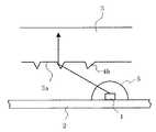
図4を用いて上述の同心円凹プリズム群4aを詳細に説明する。ここでは、光制御板3の表面に形成されている同心円凹プリズム群4aの断面形状は、プリズムを形成する外周面が光制御板3の光出射面に対してほぼ垂直になっており、内周面はプリズム断面の頂角が40〜50度となるように形成されている。この角度は光制御板3から出射される光出射角により決定される。例えば、出射光が光制御板3からほぼ垂直に出射するようにするには、同心円凹プリズムの1つに入射する光に対して、そのプリズムの頂角が90度からLED光の光制御板3の裏面への入射角を引いた値になるようにすれば良い。この場合には、LED光源1に近いプリズムの頂角は、それよりも遠いプリズムの頂角よりも大きい角度になる。 The above-mentioned concentric
また、同心円凹プリズム群4aの外周にあるプリズムに入射する光ほどその強度が弱くなる。これは、このような光に対しては、LED光源1の輻射強度が弱い上に、光制御板3の裏面での反射率が大きくなるためである。そのため、同心円凹プリズム群4aの深さは、外周に行くほど深くなるように形成されている。具体的には、プリズムに入射する光強度と深さとの積がおよそ一定になるように設計されている。 Moreover, the intensity | strength becomes weak, so that the light which injects into the prism in the outer periphery of the concentric
このようにして、本発明の照明装置の出射角を制御すると同時に輝度分布の良好な照明装置を実現することができた。また、図4で示した同心円凹プリズムの間隙に存在する平坦部3aの幅を調節することによって、出射光強度分布を変えることが可能である。同心円凹プリズム群4aの深さだけで出射光強度分布の調節が可能な場合は、平坦部3aを省略することができる。 In this way, it was possible to realize an illuminating device having a good luminance distribution while controlling the emission angle of the illuminating device of the present invention. Further, by adjusting the width of the
図5は、本実施例の照明装置を模式的に示す部分断面図である。本実施例では、光制御板3のモールド5に対応する位置にモールド5の表面形状と相似な凹部9が形成され、回路基板2と光制御板3との間隙に光反射層7が設けられている。凹部9を形成することによってLED光源1からの光は凹部9の表面でほとんど屈折されずに光制御板3の内部に導入することとなり、光制御板3の表面での反射損失を最小にすることができる。また、このことによって、同心円凹プリズム群4aに入射する光の入射角を、LED光源1の発光面とプリズム位置とを結んだ直線によって決めることが可能となった。このようにして得られる入射角を使って屈折の法則に基づいて計算することによって、所望の出射角を得るための同心円凹プリズムの内周面の角度を決定することができる。同心円凹プリズムの外周円の角度は、内周円の角度と光制御板3の垂線に対して鏡対称になるように決める。このようにして、同心円凹プリズム群4aの断面形状は二等辺三角形となる。同心円凹プリズム群4aの断面形状を二等辺三角形とすることによって、他のLED光源から光制御板3内部に入射し、そのままその内部を導波してきた光をも効率良く光出射面側から出力することが可能となり、輝度の向上をはかることができた。 FIG. 5 is a partial cross-sectional view schematically showing the illumination device of the present embodiment. In this embodiment, a
本実施例においても、同心円凹プリズム群4aの頂角を同心円の内側に行くほど大きくすることで、より指向性の高い照明が可能となる。また、同心円凹プリズム群4aの深さを同心円の内側に行くほど浅くすることによって、より一様な輝度分布の照明を実現することが可能となる。また、実施例1と同様に、同心円凹プリズムの間隙に存在する平坦部3aの幅を調節することによって、出射光強度分布を変えることが可能である。同心円凹プリズム群4aの深さだけで出射光強度分布の調節が可能な場合は、平坦部3aを省略することができる。 Also in this embodiment, by increasing the apex angle of the concentric
また、同心円凹プリズムの表面で反射した光は、全反射臨界角よりも小さな角度で光制御板3の内部に戻って、光制御板3の裏面を透過してしまうため損失光となる。この損失光を再利用して有効に用いるために回路基板2と光制御板3の間に光反射層7が配されている。この光反射層7は、フィルム上にAgやAlなどの反射率の高い金属を蒸着したものや、反射率の高い白色顔料を透明フィルム内に混合したり表面に塗布したりしたものを用いることができる。この光反射層7は、回路基板2の表面や光制御板3の裏面に直接形成しても良い。これにより、照明装置の輝度を向上させることができる。 Further, the light reflected by the surface of the concentric concave prism returns to the inside of the
さらに、光制御板3の光出射面に形成されている同心円凹プリズム群の中心に部分透過鏡8を配した。LED光源1として、低角輻射光強度が弱く高角輻射光強度が大きなLED光源を用いる場合は、この部分透過鏡8を省略することができるが、一般のLED光源は低角輻射光強度が大きいために、同心円凹プリズム群4aの中心部の出射光強度が際立って大きくなる。部分透過鏡8は、このLED光源1の低角輻射光を所定の割合だけ透過し、それ以外の光を反射して再利用しようとするものである。この部分透過鏡8としては、AlやAgやCrなどの金属をマスク蒸着したり、カーボンなどの黒色顔料や黒色染料を含む樹脂を印刷したりすることで形成することができる。その透過率は形成する部分透過鏡8の膜厚によって調節することができる。あるいはまた、部分透過鏡に複数の開口を設けて、この開口面積を調節することによっても透過率の調節をすることができる。 Further, a partial transmission mirror 8 is arranged at the center of the concentric concave / convex prism group formed on the light exit surface of the
さらに、この部分透過鏡8の透過率が、LED光源1からの輻射強度に合わせて、中心部の透過率を低く、周辺部の透過率を高くなるように構成した。これによって、より均一な照明が可能となる。このような透過率分布を有する部分透過鏡を作製するには、金属蒸着時に透過率分布に合わせた複数のマスクを用いたり、上記樹脂の印刷濃度分布を調節したり、開口分布を調節することによって可能となる。 Further, the transmittance of the partial transmission mirror 8 is configured such that the transmittance at the center portion is low and the transmittance at the peripheral portion is high in accordance with the radiation intensity from the LED
図4では部分透過鏡8は光制御板3の光出射面側に形成したが、凹部9の内面やモールド5の表面に形成しても良い。このように凹部9やモールド5の表面に形成することによって、LED光源1の真上の光強度分布のみならず、実質的にLED光源1からの輻射光強度分布そのものを制御するのと同様の効果を得ることが可能となり、より光強度分布の均一化をはかれる。あるいは、部分透過鏡8を光制御板3の内部にサンドイッチする形で形成しても良い。 In FIG. 4, the partial transmission mirror 8 is formed on the light exit surface side of the
本実施例によって、LED光源1からの光の利用効率が良くなると同時に、よりLED光源1から離れた場所まで光を導くことが可能となり、従来のサイドライト型照明装置に用いられるLED光源の使用個数をおよそ半分に減らすことができた。 According to the present embodiment, the light use efficiency from the LED
図6は本実施例の照明装置の構成を模式的に示す断面図である。本実施例では、同心円プリズムとして、光制御板3の光入射面に同心円凸プリズム4bが設けられている。この同心円凸プリズム4bはLED光源1の真上に中心を持って配置されている。LED光源1やモールド5に関しては、前述の実施例と同様なのでその説明を省略する。 FIG. 6 is a cross-sectional view schematically showing the configuration of the illumination device of this embodiment. In the present embodiment, a concentric
図6の矢印で示されるように、LED光源1から出射した光はモールド5を介して同心円凸プリズムの内周面から光制御板3の内部に入り、その外周面で全反射されて光制御板3の光出射面から出射される。前述の実施例と同様に、同心円凸プリズム群4bの断面形状を調節することによって、出射広がり角を調節することができる。これにより、視角特性を任意に調整することが可能になる。 As indicated by the arrows in FIG. 6, the light emitted from the LED
図7を用いて上述の同心円凸プリズム群4bを詳細に説明する。LED光源1から出射した光は、図中の矢印で示されるようにモールド5を介して同心円凸プリズム群4bの内周面に入射した後、同じプリズムの外周面で全反射されて光制御板3の光出射面から出射する。ここでは、同心円凸プリズムの内周面に入射した光が内周面に対して垂直に入射するように構成されている。このとき、入射時の反射損失が最小となっている。また、外周面で反射された後の出射角は外周面の角度を変えることによって調整することができる。 The above-mentioned concentric
内周面に対してLED光源1からの光を垂直に入射させるためには、内周面が光制御板3の裏面に立てた垂線となす角度と、LED光源1からの光と光制御板3の裏面とがなす角度とを等しくして内周面角とすれば良い。実際はLED光源1の発光面は広がりを持っているために、内周面角度近傍の角度で最適化が図られる。 In order for the light from the LED
一方、同心円凸プリズム群4bの外周面が光制御板3の裏面に立てた垂線となす角度の2倍が、90度からLED光源1からの光と光制御板3の裏面とがなす角度を引いた値になるようにすれば、外周面で反射された光が光制御板3の光出射面から垂直に出射する。実際はLED光源1の発光面は広がりを持っているために、外周面角度近傍の角度で最適化が図られる。また、光制御板3からの光出射方向を垂直出射からズラす場合は、外周面の角度を前記計算値からずらせてやれば良い。このずらせた角度の2倍の角度だけ出射光の角度を変化させることができる。このように、同心円凸プリズム群の頂角は同心円の内側になるに従って大きくなり、その断面形状も変化する。 On the other hand, twice the angle formed by the outer peripheral surface of the concentric
また、同心円凸プリズム群4bの間隙の平坦部3aの幅を調節することによって、出射光強度分布を制御することができる。すなわち、一般に同心円凸プリズム群4bの外周に行くほどLED光源1からの照射光強度は弱くなるために、外周に形成される平坦部3aの幅を狭くすることで光制御板1からの出射光強度を均一にすることができる。設計上は、プリズム最外周近傍においては、この平坦部3aを省略しても良い。 Further, the intensity distribution of the emitted light can be controlled by adjusting the width of the
図8は、本実施例の照明装置を模式的に示す部分断面図である。本実施例では、図5で示した構成と同様に、回路基板2と光制御板3の間に光反射層7が配されており、また光制御板3の光出射面におけるLED光源1の真上に部分透過鏡8が配されている。 FIG. 8 is a partial cross-sectional view schematically showing the illumination device of the present embodiment. In the present embodiment, a
光制御板3の内面や平坦部3aで反射した光は、光制御板3の裏面を透過するため損失光となる。この損失光を再利用して有効に用いるために光反射層7が配されている。この光反射層7は、フィルム上にAgやAlなどの反射率の高い金属を蒸着したものや、反射率の高い白色顔料を透明フィルム内に混合したり表面に塗布したりしたものを用いることができる。この光反射層7は、より回路基板2の近傍に配置されており、回路基板2の表面に直接形成しても良い。このような構成により、照明装置の輝度を向上できる。 The light reflected by the inner surface of the
一方、図5の場合と同様に、LED光源1に低角輻射光強度が弱く高角輻射光強度が大きなLED光源を用いる場合は、この部分透過鏡8を省略することができるが、一般の安価なLED光源は低角輻射光強度が大きいために、同心円凸プリズム群4bの中心部の出射光強度が際立って大きくなる。部分透過鏡8は、このLED光源1の低角輻射光を所定の割合だけ透過し、それ以外の光を反射して再利用しようとするものである。この部分透過鏡8としては、AlやAgやCrなどの金属をマスク蒸着したり、カーボンなどの黒色顔料や黒色染料を含む樹脂を印刷したりすることで形成することができる。その透過率は形成する部分透過鏡8の膜厚によって調節することができる。あるいはまた、部分透過鏡に複数の開口を設けて、この開口面積を調節することによっても透過率の調節をすることができる。さらにまた、この部分透過鏡8の透過率を、LED光源1からの輻射強度に合わせて、中心部の透過率を低く、周辺部の透過率を低くすることによって、より均一な照明が可能となる。このような透過率分布を有する部分透過鏡を作製するには、金属蒸着時に透過率分布に合わせた複数のマスクを用いたり、樹脂の印刷濃度分布を調節したりすればよい。本実施例では、部分反射鏡8が光制御板3の光出射面側に形成されている場合を示したが、裏面側やモールド5の表面に形成しても良い。 On the other hand, as in the case of FIG. 5, in the case where an LED light source having a low low-angle radiant light intensity and a high high-angle radiant light intensity is used as the
図9は、上述した構成の照明装置を用いた表示装置を模式的に示す斜視図である。ここでは、非自発光型の表示素子として液晶表示素子を用いた実施例を示している。図示するように、本実施例の表示装置は、上述した構成を持つ照明装置10を用いて液晶素子13を照明している。照明装置10と液晶素子13の間には、拡散シート11とプリズムシート12が設けられている。照明装置10のLED光源が実装された回路基板には、LED光源に電力を供給するためのコネクタケーブル14が配されている。また、液晶素子13にはこれに画像信号と電力を供給するコネクタケーブル15が配されている。 FIG. 9 is a perspective view schematically showing a display device using the illumination device having the above-described configuration. Here, an example in which a liquid crystal display element is used as a non-self-luminous display element is shown. As shown in the figure, the display device of this example illuminates the
照明装置から照射された光は、拡散シート11で拡散されてより均一な光となり、プリズムシート12に入射する。プリズムシート12は、略直角の頂角を持った平行な稜線を持ったプリズム群が形成された透明なシートであり、稜線に垂直な方向の光成分をより垂直にそろえる機能をする。図9ではプリズムシート12は1枚だけが図示されているが、互いに直交した稜線を持った2枚のプリズムシートを配しても良い。照明装置10の出射光が光制御板から垂直になるようにした場合は、プリズムシート12を省略することができる。また、図8に示すように照明装置10内部に拡散板を配する場合は、拡散シート11を省略することができる。さらに、図4や図8に示すように照明装置10の内部に光反射層を形成する場合は、照明装置10と液晶素子13との間隙に選択反射偏光子を配することによって、光利用効率を向上させることができる。液晶素子13としては単純マトリックス型液晶素子でも、アクティブマトリックス型液晶素子でも用いることができる。このような構成の液晶表示装置は、少ない光源数で明るい画像を表示することができる。 The light emitted from the illumination device is diffused by the
1 LED光源
2 回路基板
3 光制御板
4 同心円プリズム群
5 モールド
6 光拡散板
7 光反射層
8 部分透過鏡
10 照明装置
11 拡散シート
12 プリズムシート
13 液晶素子
14、15 コネクタケーブルDESCRIPTION OF
Claims (13)
Translated fromJapanesePriority Applications (1)
| Application Number | Priority Date | Filing Date | Title |
|---|---|---|---|
| JP2005166954AJP2006344409A (en) | 2005-06-07 | 2005-06-07 | Light fixture, and display device provided with the same |
Applications Claiming Priority (1)
| Application Number | Priority Date | Filing Date | Title |
|---|---|---|---|
| JP2005166954AJP2006344409A (en) | 2005-06-07 | 2005-06-07 | Light fixture, and display device provided with the same |
Publications (1)
| Publication Number | Publication Date |
|---|---|
| JP2006344409Atrue JP2006344409A (en) | 2006-12-21 |
Family
ID=37641225
Family Applications (1)
| Application Number | Title | Priority Date | Filing Date |
|---|---|---|---|
| JP2005166954APendingJP2006344409A (en) | 2005-06-07 | 2005-06-07 | Light fixture, and display device provided with the same |
Country Status (1)
| Country | Link |
|---|---|
| JP (1) | JP2006344409A (en) |
Cited By (17)
| Publication number | Priority date | Publication date | Assignee | Title |
|---|---|---|---|---|
| WO2008075743A1 (en) | 2006-12-21 | 2008-06-26 | Kumiai Chemical Industry Co., Ltd. | Herbicide composition |
| JP2009026765A (en)* | 2007-07-19 | 2009-02-05 | Samsung Electro Mech Co Ltd | Backlight unit |
| JP2009105070A (en)* | 2007-07-19 | 2009-05-14 | Samsung Electro Mech Co Ltd | Backlight unit |
| WO2009072429A1 (en)* | 2007-12-07 | 2009-06-11 | Sony Corporation | Light source apparatus and display apparatus |
| WO2009072418A1 (en)* | 2007-12-07 | 2009-06-11 | Sony Corporation | Illuminating device and display device |
| JP2010122689A (en)* | 2008-11-21 | 2010-06-03 | Samsung Electronics Co Ltd | Display apparatus |
| US7794100B2 (en) | 2006-12-27 | 2010-09-14 | Sony Corporation | Planar light source apparatus, display apparatus and planar illumination method |
| KR100983280B1 (en)* | 2008-02-05 | 2010-09-24 | 엘지전자 주식회사 | Backlight unit |
| JP2010217349A (en)* | 2009-03-13 | 2010-09-30 | Hitachi Displays Ltd | Liquid crystal display |
| US7967462B2 (en) | 2008-02-12 | 2011-06-28 | Hitachi, Ltd. | Backlight assembly for liquid crystal display apparatus having inclined light emmitting elements |
| JP2012084425A (en)* | 2010-10-13 | 2012-04-26 | Enplas Corp | Lighting system |
| WO2012077368A1 (en)* | 2010-12-10 | 2012-06-14 | 電気化学工業株式会社 | β TYPE SIALON, LIGHT-EMITTING DEVICE AND APPLICATION THEREOF |
| WO2012095905A1 (en)* | 2011-01-14 | 2012-07-19 | パナソニック株式会社 | Illumination light source |
| CN102630288A (en)* | 2009-09-25 | 2012-08-08 | 科锐公司 | Lighting fixtures with low glare and high brightness level uniformity |
| JP2013505549A (en)* | 2009-09-21 | 2013-02-14 | コーニンクレッカ フィリップス エレクトロニクス エヌ ヴィ | LIGHT EMITTING DEVICE HAVING LIGHT GUIDE PLATE HAVING REFLECTIVE Shielding Unit Accompanied With Glare |
| KR101373600B1 (en) | 2012-06-28 | 2014-03-12 | 국민대학교산학협력단 | Transparent lens of led module assembly and apparatus for displaying traffic information using it |
| JP2021514488A (en)* | 2018-02-21 | 2021-06-10 | バルブ コーポレーション | Head-mounted display with narrow-angle backlight |
- 2005
- 2005-06-07JPJP2005166954Apatent/JP2006344409A/enactivePending
Cited By (28)
| Publication number | Priority date | Publication date | Assignee | Title |
|---|---|---|---|---|
| WO2008075743A1 (en) | 2006-12-21 | 2008-06-26 | Kumiai Chemical Industry Co., Ltd. | Herbicide composition |
| US7794100B2 (en) | 2006-12-27 | 2010-09-14 | Sony Corporation | Planar light source apparatus, display apparatus and planar illumination method |
| US8764212B2 (en) | 2007-07-19 | 2014-07-01 | Samsung Electronics Co., Ltd. | Backlight unit |
| US9519184B2 (en) | 2007-07-19 | 2016-12-13 | Samsung Electronics Co., Ltd. | Backlight unit |
| JP2009105070A (en)* | 2007-07-19 | 2009-05-14 | Samsung Electro Mech Co Ltd | Backlight unit |
| US8220944B2 (en) | 2007-07-19 | 2012-07-17 | Samsung Led Co., Ltd. | Backlight unit |
| JP2009026765A (en)* | 2007-07-19 | 2009-02-05 | Samsung Electro Mech Co Ltd | Backlight unit |
| WO2009072429A1 (en)* | 2007-12-07 | 2009-06-11 | Sony Corporation | Light source apparatus and display apparatus |
| WO2009072418A1 (en)* | 2007-12-07 | 2009-06-11 | Sony Corporation | Illuminating device and display device |
| JP2009140829A (en)* | 2007-12-07 | 2009-06-25 | Sony Corp | Lighting device, and display device |
| JP2009158462A (en)* | 2007-12-07 | 2009-07-16 | Sony Corp | Light source device and display device |
| US8770773B2 (en) | 2007-12-07 | 2014-07-08 | Dexerials Corporation | Light source device and display device |
| US8403512B2 (en) | 2007-12-07 | 2013-03-26 | Sony Corporation | Illumination apparatus and display apparatus |
| KR100983280B1 (en)* | 2008-02-05 | 2010-09-24 | 엘지전자 주식회사 | Backlight unit |
| US7967462B2 (en) | 2008-02-12 | 2011-06-28 | Hitachi, Ltd. | Backlight assembly for liquid crystal display apparatus having inclined light emmitting elements |
| US8638281B2 (en) | 2008-11-21 | 2014-01-28 | Samsung Display Co., Ltd. | Display apparatus including an optical plate and method of manufacturing the same |
| JP2010122689A (en)* | 2008-11-21 | 2010-06-03 | Samsung Electronics Co Ltd | Display apparatus |
| JP2010217349A (en)* | 2009-03-13 | 2010-09-30 | Hitachi Displays Ltd | Liquid crystal display |
| JP2013505549A (en)* | 2009-09-21 | 2013-02-14 | コーニンクレッカ フィリップス エレクトロニクス エヌ ヴィ | LIGHT EMITTING DEVICE HAVING LIGHT GUIDE PLATE HAVING REFLECTIVE Shielding Unit Accompanied With Glare |
| CN102630288A (en)* | 2009-09-25 | 2012-08-08 | 科锐公司 | Lighting fixtures with low glare and high brightness level uniformity |
| CN102630288B (en)* | 2009-09-25 | 2015-09-09 | 科锐公司 | Lighting fixtures with low glare and high brightness level uniformity |
| JP2012084425A (en)* | 2010-10-13 | 2012-04-26 | Enplas Corp | Lighting system |
| WO2012077368A1 (en)* | 2010-12-10 | 2012-06-14 | 電気化学工業株式会社 | β TYPE SIALON, LIGHT-EMITTING DEVICE AND APPLICATION THEREOF |
| US9028719B2 (en) | 2010-12-10 | 2015-05-12 | Denki Kagaku Kogyo Kabushiki Kaisha | β- sialon, and light emitting device and applications thereof |
| WO2012095905A1 (en)* | 2011-01-14 | 2012-07-19 | パナソニック株式会社 | Illumination light source |
| KR101373600B1 (en) | 2012-06-28 | 2014-03-12 | 국민대학교산학협력단 | Transparent lens of led module assembly and apparatus for displaying traffic information using it |
| JP2021514488A (en)* | 2018-02-21 | 2021-06-10 | バルブ コーポレーション | Head-mounted display with narrow-angle backlight |
| US12422675B2 (en) | 2018-02-21 | 2025-09-23 | Valve Corporation | Head-mounted display with narrow angle backlight |
Similar Documents
| Publication | Publication Date | Title |
|---|---|---|
| US7210839B2 (en) | Backlight system and liquid crystal display employing the same | |
| US7597467B2 (en) | Lighting unit and liquid crystal display device using the lighting unit | |
| KR100644935B1 (en) | Planar light-emitting device | |
| CN110914746B (en) | Optical Lenses for Ultra-Thin Direct Backlights | |
| JP5550505B2 (en) | Planar illumination device and liquid crystal display device including the same | |
| CN100410768C (en) | Backlight system and liquid crystal display using the backlight system | |
| US7447416B2 (en) | Light emitting assembly, backlight unit and display having the same | |
| US20110051044A1 (en) | Light quantity control member, surface light source unit and display device | |
| CN100429570C (en) | Surface light source device and display device equipped with the device | |
| JP2006344409A (en) | Light fixture, and display device provided with the same | |
| CN109164638B (en) | Light emitting module, manufacturing method thereof and direct type backlight source | |
| JP2008059786A (en) | Lighting apparatus and display device provided with the same | |
| JP2006173624A (en) | LED light source | |
| JP2004206916A (en) | Planar light source | |
| JP2006031941A (en) | Planar light source unit | |
| JP2004520695A (en) | Lighting system and display device | |
| US7543965B2 (en) | Side light-emitting device, backlight unit having the side light-emitting device, and liquid crystal display apparatus employing the backlight unit | |
| TWI671574B (en) | Light source module and display appartus | |
| TW202028822A (en) | Light source module and display appartus | |
| WO2012035799A1 (en) | Lighting device | |
| WO2018214618A1 (en) | Backlight module and liquid crystal display device | |
| CN101321986A (en) | Light guide member, surface light source device having the light guide member, and display apparatus using the surface light source device | |
| JP2012204336A (en) | Illumination device and display device | |
| CN109031510B (en) | A light guide plate and its manufacturing method, a backlight module and a display device | |
| CN100452459C (en) | Luminescent light source and luminescent light source array |