JP2006343500A - Light source device and projection optical device - Google Patents
Light source device and projection optical deviceDownload PDFInfo
- Publication number
- JP2006343500A JP2006343500AJP2005168360AJP2005168360AJP2006343500AJP 2006343500 AJP2006343500 AJP 2006343500AJP 2005168360 AJP2005168360 AJP 2005168360AJP 2005168360 AJP2005168360 AJP 2005168360AJP 2006343500 AJP2006343500 AJP 2006343500A
- Authority
- JP
- Japan
- Prior art keywords
- signal
- video signal
- rotation
- input video
- motor
- Prior art date
- Legal status (The legal status is an assumption and is not a legal conclusion. Google has not performed a legal analysis and makes no representation as to the accuracy of the status listed.)
- Pending
Links
- 230000003287optical effectEffects0.000titleclaimsabstractdescription49
- 238000001514detection methodMethods0.000claimsdescription63
- 238000005286illuminationMethods0.000claimsdescription9
- 239000000284extractSubstances0.000claimsdescription4
- 238000010586diagramMethods0.000description14
- 238000012545processingMethods0.000description14
- 238000006243chemical reactionMethods0.000description9
- 238000005070samplingMethods0.000description9
- 238000005259measurementMethods0.000description5
- 239000004973liquid crystal related substanceSubstances0.000description4
- 230000015572biosynthetic processEffects0.000description3
- 230000001360synchronised effectEffects0.000description3
- 238000003786synthesis reactionMethods0.000description3
- 230000001186cumulative effectEffects0.000description2
- 230000007274generation of a signal involved in cell-cell signalingEffects0.000description2
- 230000008033biological extinctionEffects0.000description1
- 239000003086colorantSubstances0.000description1
- 238000004891communicationMethods0.000description1
- 238000012937correctionMethods0.000description1
- 230000005669field effectEffects0.000description1
- 230000004907fluxEffects0.000description1
- 238000012538light obscurationMethods0.000description1
- 239000011159matrix materialSubstances0.000description1
- QSHDDOUJBYECFT-UHFFFAOYSA-NmercuryChemical compound[Hg]QSHDDOUJBYECFT-UHFFFAOYSA-N0.000description1
- 229910052753mercuryInorganic materials0.000description1
- 238000000034methodMethods0.000description1
- 238000012986modificationMethods0.000description1
- 230000004048modificationEffects0.000description1
- 230000002093peripheral effectEffects0.000description1
- 230000010287polarizationEffects0.000description1
- 230000008569processEffects0.000description1
- 230000000750progressive effectEffects0.000description1
- 238000000926separation methodMethods0.000description1
- 230000007704transitionEffects0.000description1
Images


Classifications
- G—PHYSICS
- G03—PHOTOGRAPHY; CINEMATOGRAPHY; ANALOGOUS TECHNIQUES USING WAVES OTHER THAN OPTICAL WAVES; ELECTROGRAPHY; HOLOGRAPHY
- G03B—APPARATUS OR ARRANGEMENTS FOR TAKING PHOTOGRAPHS OR FOR PROJECTING OR VIEWING THEM; APPARATUS OR ARRANGEMENTS EMPLOYING ANALOGOUS TECHNIQUES USING WAVES OTHER THAN OPTICAL WAVES; ACCESSORIES THEREFOR
- G03B21/00—Projectors or projection-type viewers; Accessories therefor
- G03B21/14—Details
- G03B21/20—Lamp housings
- G03B21/2006—Lamp housings characterised by the light source
- G03B21/2013—Plural light sources
- G—PHYSICS
- G03—PHOTOGRAPHY; CINEMATOGRAPHY; ANALOGOUS TECHNIQUES USING WAVES OTHER THAN OPTICAL WAVES; ELECTROGRAPHY; HOLOGRAPHY
- G03B—APPARATUS OR ARRANGEMENTS FOR TAKING PHOTOGRAPHS OR FOR PROJECTING OR VIEWING THEM; APPARATUS OR ARRANGEMENTS EMPLOYING ANALOGOUS TECHNIQUES USING WAVES OTHER THAN OPTICAL WAVES; ACCESSORIES THEREFOR
- G03B21/00—Projectors or projection-type viewers; Accessories therefor
- G03B21/14—Details
- G03B21/20—Lamp housings
- G03B21/2006—Lamp housings characterised by the light source
- G03B21/2033—LED or laser light sources
- G—PHYSICS
- G03—PHOTOGRAPHY; CINEMATOGRAPHY; ANALOGOUS TECHNIQUES USING WAVES OTHER THAN OPTICAL WAVES; ELECTROGRAPHY; HOLOGRAPHY
- G03B—APPARATUS OR ARRANGEMENTS FOR TAKING PHOTOGRAPHS OR FOR PROJECTING OR VIEWING THEM; APPARATUS OR ARRANGEMENTS EMPLOYING ANALOGOUS TECHNIQUES USING WAVES OTHER THAN OPTICAL WAVES; ACCESSORIES THEREFOR
- G03B21/00—Projectors or projection-type viewers; Accessories therefor
- G03B21/14—Details
- G03B21/20—Lamp housings
- G03B21/2053—Intensity control of illuminating light
Landscapes
- Physics & Mathematics (AREA)
- General Physics & Mathematics (AREA)
- Optics & Photonics (AREA)
- Engineering & Computer Science (AREA)
- Multimedia (AREA)
- Signal Processing (AREA)
- Projection Apparatus (AREA)
Abstract
Description
Translated fromJapanese本発明は、投射面に画像を表示するプロジェクタに用いられる光源装置及び投影光学装置に関するもので、特に、各種のレートの入力ビデオ信号に対応させるようにしたものに関する。 The present invention relates to a light source device and a projection optical device that are used in a projector that displays an image on a projection surface, and more particularly to a device that is adapted to input video signals of various rates.
近年、小型のプロジェクタでは、画像データに応じてマトリクス状に配列された各画素の微小ミラーをPWM(Pulse Width Modulation)駆動によりオン状態とオフ状態の角度に高速に切り替えて照明光を変調するDMD(Digital Micromirror Device)素子のような空間光変調素子が使われ始めている。 In recent years, in a small projector, a DMD that modulates illumination light by switching a minute mirror of each pixel arranged in a matrix according to image data to an angle between an ON state and an OFF state at high speed by PWM (Pulse Width Modulation) drive Spatial light modulation elements such as (Digital Micromirror Device) elements are beginning to be used.
空間光変調素子では、従来の液晶表示素子と異なり、高速動作が可能であるため、R(赤)、G(緑)、B(青)の画像を面順次方式で表示することができる。また、液晶表示素子を用いたプロジェクタでは、カラー画像を表示するのに3枚のLCD(Liquid Crystal Display)素子が必要であるのに対し、空間光変調素子を用いたプロジェクタでは、1つのDMD素子でカラー表示を行うことができる。 Unlike the conventional liquid crystal display element, the spatial light modulation element can operate at high speed, so that images of R (red), G (green), and B (blue) can be displayed in a frame sequential manner. In addition, a projector using a liquid crystal display element requires three LCD (Liquid Crystal Display) elements to display a color image, whereas a projector using a spatial light modulation element has one DMD element. Can be used for color display.
このような空間光変調素子を用いたプロジェクタでは、従来、光源として水銀ランプ等の白色光のランプが用いられている。すなわち、従来の空間光変調素子を用いたプロジェクタでは、入力ビデオ信号を面順次の画像信号に変換して空間光変調素子に供給し、RGBに塗り分けられたカラーホイールを入力画像の垂直同期信号に同期して回転させ、或いは、カラーホイールの回転に同期してビデオ信号のレートを変化させ、ランプからの光をカラーホイールを介して空間光変調素子に照射するようにしている。しかしながら、プロジェクタの光源としてランプを用いると、消費電力が大きくなると共に、カラーホイールが必要となる。 In a projector using such a spatial light modulation element, a white light lamp such as a mercury lamp is conventionally used as a light source. That is, in a projector using a conventional spatial light modulation element, an input video signal is converted into a frame-sequential image signal and supplied to the spatial light modulation element. The rate of the video signal is changed in synchronization with the rotation of the color wheel, and the light from the lamp is irradiated to the spatial light modulation element through the color wheel. However, when a lamp is used as the light source of the projector, power consumption increases and a color wheel is required.
これに対して、近年、このようなプロジェクタの光源として、LEDを用いることが検討されている。LEDは、ランプに比べて、小型、高耐性、長寿命、低消費電力などの利点がある。また、RGBの3色のLEDを用いれば、カラーホイールは不要となり、然も、優れた色再現性が得られる。更に、空間光変調素子を用いた場合には、液晶表示素子のような偏光依存性が無いため、LEDなどの無偏光の光を発生する光源に対して、損失の少ない光学系が簡単に構成できる。 On the other hand, in recent years, it has been studied to use an LED as a light source of such a projector. Compared with a lamp, the LED has advantages such as small size, high durability, long life, and low power consumption. If RGB three-color LEDs are used, a color wheel becomes unnecessary, and excellent color reproducibility can be obtained. Furthermore, when a spatial light modulator is used, there is no polarization dependency like a liquid crystal display device, so an optical system with little loss can be easily configured for a light source that generates non-polarized light such as an LED. it can.
しかしながら、LEDを直流駆動した場合には、LEDに流せる電流には限界がある。そこで、本願出願人は、例えば特許文献1〜特許文献3に示されるように、複数のLEDが円周上に配置された回転光学系を用いることを提案している。 However, when the LED is DC driven, there is a limit to the current that can be passed through the LED. Therefore, the applicant of the present application has proposed using a rotating optical system in which a plurality of LEDs are arranged on the circumference, as shown in
このような回転光学系では、RGBの複数のLEDが円周上に配置され、この複数のLEDに沿って回転する光学系のロッドが設けられる。複数のLEDが順次パルス駆動され、複数のLEDが順次パルス点灯される。そして、LEDの点灯に合わせて光学系のロッドが回転され、点灯中のLEDの光が集められて、空間光変調素子に向けて照射される。 In such a rotating optical system, a plurality of RGB LEDs are arranged on the circumference, and a rod of an optical system that rotates along the plurality of LEDs is provided. The plurality of LEDs are sequentially pulse-driven, and the plurality of LEDs are sequentially pulsed. Then, the rod of the optical system is rotated in accordance with the lighting of the LED, and the light of the LED being turned on is collected and irradiated toward the spatial light modulation element.
LEDを直流駆動した場合には流せる電流に限界があるが、回転光学系を用いた場合には、上述のように、LEDはパルス駆動となる。このため、LEDに大電流を流すことができ、強い発光が得られる。そして、このような回転光学系を用いると、光学系のロッドにより、点灯中のLEDの光が集められるので、LEDを連続点灯させたのと等価になる。
このようなプロジェクタでは、パーソナルコンピュータ等からのRGBカラービデオ信号と、NTSC(National Television System Communication)方式等のカラービデオ信号が入力される。例えばパーソナルコンピュータからのアナログRGBビデオ信号の水平同期信号及び垂直同期信号は、その出力ビデオ信号の解像度に応じて、極性、タイミング、周波数がVESA(Video Electronics Standards Association)等で規定されている。ところが、パーソナルコンピュータによっては、規格外の極性やタイミングのビデオ信号を出力する場合がある。このため、このようなプロジェクタでは、規格外の極性やタイミングのビデオ信号でも対応できるようにする必要がある。 In such a projector, an RGB color video signal from a personal computer or the like and a color video signal of the NTSC (National Television System Communication) system or the like are input. For example, the horizontal sync signal and vertical sync signal of an analog RGB video signal from a personal computer are specified by VESA (Video Electronics Standards Association) or the like in accordance with the resolution of the output video signal. However, some personal computers may output video signals with non-standard polarity and timing. For this reason, it is necessary for such a projector to be able to cope with video signals with non-standard polarity and timing.
また、このようなプロジェクタでは、各種のビデオ信号が入力されることから、それに伴って、LEDの発光タイミングや発光時間、光学ロッドの位相や回転数を適宜設定する必要がある。 In such a projector, since various video signals are input, it is necessary to appropriately set the light emission timing and light emission time of the LED, and the phase and rotation speed of the optical rod.
また、このようなプロジェクタでは、立ち上げ時に光学ロッドを回転させるモータを入力ビデオ信号のレートに応じた所望の回転数まで制御するとき、入力信号の態様が途中で変化するとき、又は、入力信号が無信号のとき等で、各種の問題が発生することが想定される。 In such a projector, when the motor that rotates the optical rod at the time of start-up is controlled to a desired number of rotations according to the rate of the input video signal, when the mode of the input signal changes in the middle, or when the input signal It is assumed that various problems occur when no signal is present.
本発明は、上述の従来の課題を鑑み、規格外の極性やタイミングのビデオ信号を含む各種の信号レートのビデオ信号に柔軟に適応できるようにした光源装置及び投影光学装置を提供することを目的とするものである。 SUMMARY OF THE INVENTION In view of the above-described conventional problems, an object of the present invention is to provide a light source device and a projection optical device that can flexibly adapt to video signals of various signal rates including video signals of non-standard polarity and timing. It is what.
上述の課題を解決するために、請求項1の発明は、入力ビデオ信号の種別を検出するビデオ種別検出手段と、照明光を射出する複数の発光ダイオードと、発光ダイオードの点灯状態を制御する点灯制御手段とを有し、点灯制御手段は、ビデオ種別検出手段が検出したビデオ信号の種別に基づいて、発光ダイオードの点灯制御を行うようにした光源装置である。 In order to solve the above-described problem, the invention of
請求項2の発明では、ビデオ種別検出手段は、入力ビデオ信号の同期信号を抽出し、入力ビデオ信号の同期信号の周期から、入力ビデオ信号の種別を判断するようにしたことを特徴とする。 According to a second aspect of the present invention, the video type detection means extracts the synchronization signal of the input video signal, and determines the type of the input video signal from the period of the synchronization signal of the input video signal.
請求項3の発明では、ビデオ種別検出手段は、入力ビデオ信号の同期信号を抽出し、入力ビデオ信号の同期信号のデューティー比から、入力ビデオ信号の種別を判断するようにしたことを特徴とする。 According to a third aspect of the present invention, the video type detection means extracts the synchronization signal of the input video signal and determines the type of the input video signal from the duty ratio of the synchronization signal of the input video signal. .
請求項4の発明では、光源装置は、円周上に配置された複数の発光ダイオードから出射した照明光を取り込む光学ロッドと、光学ロッドを回転させるモータと、モータの回転を制御する回転制御手段とを更に有し、ビデオ種別検出手段の検出出力に基づいて、光学ロッドの回転の制御を行うようにしたことを特徴とする。 In the invention of claim 4, the light source device includes an optical rod that takes in illumination light emitted from a plurality of light emitting diodes arranged on the circumference, a motor that rotates the optical rod, and a rotation control unit that controls the rotation of the motor. And the rotation of the optical rod is controlled based on the detection output of the video type detection means.
請求項5の発明では、回転制御手段は、入力ビデオ信号の2垂直周期の期間を単位として、2垂直周期の期間で整数回、光学ロッドを回転させるモータを制御するようにしたことを特徴とする。 The invention according to
請求項6の発明では、点灯制御手段は、入力ビデオ信号の2垂直周期の期間を単位として、発光量が略等しくなるように発光ダイオードを制御するようにしたことを特徴とする。 According to a sixth aspect of the present invention, the lighting control means controls the light emitting diodes so that the light emission amounts are substantially equal in units of two vertical periods of the input video signal.
請求項7の発明では、回転制御手段は、同期信号に対するロッドの回転の追従状態を検知する検知手段を有し、検知手段により光学ロッドの回転数が所定の回転数に満たないと判断された場合には、複数の発光ダイオードを消灯するようにしたことを特徴とする。 In the invention of claim 7, the rotation control means has a detecting means for detecting a follow-up state of the rotation of the rod with respect to the synchronization signal, and the detecting means determines that the rotation speed of the optical rod is less than the predetermined rotation speed. In this case, the plurality of light emitting diodes are turned off.
請求項8の発明では、点灯制御手段は、ビデオ信号の種別により、発光ダイオードを点灯するタイミングと共に、発光ダイオードの点灯時間幅を制御するようにしたことを特徴とする。 According to an eighth aspect of the present invention, the lighting control means controls the lighting time width of the light emitting diode together with the timing of lighting the light emitting diode according to the type of the video signal.
請求項9の発明では、点灯制御手段は、固定のレート又はそれまでのビデオ信号のレートの自走垂直同期信号を発生する自走垂直同期信号発生手段を有し、
入力信号が無信号の場合には、自走垂直同期信号発生手段からの自走垂直同期信号に基づいて、光学ロッドを回転させるようにしたことを特徴とする。In the invention of claim 9, the lighting control means includes self-running vertical synchronizing signal generating means for generating a free-running vertical synchronizing signal at a fixed rate or a video signal rate up to that,
When the input signal is no signal, the optical rod is rotated based on the free-running vertical synchronization signal from the free-running vertical synchronization signal generating means.
請求項10の発明では、回転制御手段は、光学ロッドの回転が安定していなときには、光学ロッドの回転を停止させるようにしたことを特徴とする。 The invention according to
請求項11の発明は、入力ビデオ信号の種別を検出するビデオ種別検出手段と、照明光を射出する複数の発光ダイオードと、発光ダイオードの点灯状態を制御する点灯制御手段と、入力ビデオ信号に基づく駆動信号を生成する駆動信号制御手段と、駆動信号制御手段からの駆動信号により駆動される空間光変調素子とを有し、点灯制御手段は、ビデオ種別検出手段が検出したビデオ信号の種別に基づいて、発光ダイオードの点灯制御を行うようにした投影光学装置である。 The invention according to
請求項12の発明では、同期信号に対するロッドの回転の追従状態を検知する検知手段を有し、入力ビデオ信号が無信号の場合、又は、検知手段により光学ロッドの回転数が通常と異なると判断された場合には、同期信号の状態にかかわらず、空間光変調素子に所定の画像を投影するようにしたことを特徴とする。 In the invention of claim 12, it has a detection means for detecting the follow-up state of the rotation of the rod with respect to the synchronization signal, and it is determined that the input video signal is no signal or the rotation speed of the optical rod is different from the normal by the detection means. In this case, a predetermined image is projected onto the spatial light modulation element regardless of the state of the synchronization signal.
本発明によれば、入力ビデオ信号の種別が判定され、この入力ビデオ信号の種別に応じて、光学ロッドの回転数、光源の点灯タイミング及び点灯時間が適応的に設定される。これにより、各種の信号レートのビデオ信号に柔軟に適応できるようにした投影光学装置が実現できる。 According to the present invention, the type of the input video signal is determined, and the rotation speed of the optical rod, the lighting timing of the light source, and the lighting time are adaptively set according to the type of the input video signal. Thereby, it is possible to realize a projection optical apparatus that can flexibly adapt to video signals of various signal rates.
本発明によれば、入力ビデオ信号の種別を、水平同期信号及び垂直同期信号の周期、及び入力ビデオ信号の水平同期信号及び垂直同期信号のデューティー比から判定することで、規格外の極性やタイミングのビデオ信号を含めて、ビデオ信号の種別を適切に判定できる。 According to the present invention, the type of the input video signal is determined from the period of the horizontal synchronization signal and the vertical synchronization signal, and the duty ratio of the horizontal synchronization signal and the vertical synchronization signal of the input video signal, so The video signal type including the video signal can be appropriately determined.
本発明によれば、入力ビデオ信号の2垂直周期の期間を、光源の発光及び光学ロッドの回転を単位として設定することで、2垂直期間における発光量が等しくなり、入力ビデオ信号の種別が切り替わったときにも、輝度変動が生じることがなくなる。 According to the present invention, by setting the period of two vertical periods of the input video signal in units of the light emission of the light source and the rotation of the optical rod, the light emission amounts in the two vertical periods become equal, and the type of the input video signal is switched. In this case, luminance fluctuations will not occur.
本発明によれば、光学ロッドの回転数が所定の回転数に満たないと判断された場合には、複数の光源を消灯することで、乱れた画面が表示されるのを防止できる。 According to the present invention, when it is determined that the rotation speed of the optical rod is less than the predetermined rotation speed, it is possible to prevent a distorted screen from being displayed by turning off the plurality of light sources.
本発明によれば、光源の発光タイミングだけでなく、光源の点灯時間幅を制御することで、所定の期間の総光量を適切に設定でき、色ずれが生じることがなく、入力ビデオ信号のレートに応じた、輝度変動のない画面を投影することができる。 According to the present invention, by controlling not only the light emission timing of the light source but also the lighting time width of the light source, it is possible to appropriately set the total amount of light for a predetermined period, and without causing color shift, the rate of the input video signal A screen with no luminance fluctuation can be projected according to the above.
本発明によれば、入力信号が無信号の場合には、自走垂直同期信号発生手段からの自走垂直同期信号に基づいて、光学ロッドを回転させるようにしているので、入力信号が無信号になったときにも、モータの回転数が適切に保たれ、また、新たな画像の投影を再開するときの時間を短縮できる。また、これにより、LEDの発光が乱れることがなくなり、LED保護及び長寿命化が図れる。 According to the present invention, when the input signal is no signal, the optical rod is rotated based on the self-propelled vertical synchronization signal from the self-propelled vertical synchronization signal generating means. Even in this case, the number of rotations of the motor can be maintained appropriately, and the time for resuming projection of a new image can be shortened. Moreover, this prevents the emission of the LED from being disturbed, and can protect the LED and extend its life.
本発明によれば、モータが所定の回転数に達することができないときに、モータの回転を停止することにより、省電力が図れる。 According to the present invention, power can be saved by stopping the rotation of the motor when the motor cannot reach the predetermined rotational speed.
本発明によれば、入力信号が無信号のとき、又は光学ロッドの回転数が通常と異なるときに、パターン発生手段からのマスク信号又は所定のパターンの画像を投影することにより、表示乱れのある画像を見せることなくOSD(On Screen Display)表示を行うことができる。 According to the present invention, when the input signal is no signal or when the rotation speed of the optical rod is different from the normal one, there is a display disorder by projecting the mask signal from the pattern generating means or the image of the predetermined pattern. OSD (On Screen Display) display can be performed without showing an image.
以下、本発明に実施の形態について図面を参照しながら説明する。
1.全体構成
図1は、本発明が適用されたプロジェクタの構成を示すものである。図1において、入力端子1に、パーソナルコンピュータ等からのR(赤)、G(緑)、B(青)カラービデオ信号又はNTSC方式等のカラービデオ信号が供給される。Hereinafter, embodiments of the present invention will be described with reference to the drawings.
1. Overall Configuration FIG. 1 shows the configuration of a projector to which the present invention is applied. In FIG. 1, R (red), G (green), B (blue) color video signals from a personal computer or the like, or color video signals of the NTSC system or the like are supplied to an
ビデオ信号処理回路2は、入力ビデオ信号に対して、その形態に応じて、所定のビデオ信号処理を行う。入力ビデオ信号がRGBカラービデオ信号の場合、ビデオ信号処理回路2は、入力されたビデオ信号をA/D変換してディジタル化し出力する。入力ビデオ信号がNTSC等のカラービデオ信号の場合、ビデオ信号処理回路2は、入力されたビデオ信号をYC分離により輝度信号Yと色差信号UVに分離した後にA/D変換してディジタル化し出力する。 The video
DMD駆動制御回路3は、DMD駆動のための信号処理回路と、全体制御を行うCPUとが1チップ化された処理回路である。また、DMD駆動制御回路3は、設定チャンネルや音量、或いは各種の制御状態や警告情報を画面上に重畳表示させるOSD(On Screen Display)回路を含んでいる。 The DMD
DMD駆動制御回路3で、ビデオ信号処理回路2からの、輝度Yと色差UVのデジタルデータ、又は、RGBデジタルビデオデータに対して、IP変換、スケーリング、色変換、台形補正等の信号処理が行われる。ここで、IP変換は、インターレース走査からプログレシブ走査への変換である。そして、DMD駆動制御回路3からは、入力信号に基づくRGBの面順次の画像信号が出力される。面順次の画像信号は、Rの発光期間と、Gの発光期間と、Bの発光期間毎に、RGB各色のビデオ信号が発光期間毎に分割された信号である。この面順次の画像信号は、DMD駆動信号として、DMD素子5に供給される。 The DMD
DMD素子5は、その表面に多数の微小なミラーを配置し、その角度を画素毎に変えられる空間光変調素子である。DMD駆動制御回路3からのDMD駆動信号がDMD素子5に与えられると、DMD素子5の表面の微少なミラーの角度が変えられ、これにより光の進路が変えられ、画素単位で光のオン/オフが行われる。 The
また、DMD駆動制御回路3で、入力ビデオ信号の同期信号に基づいて、モータ駆動信号が生成される。このモータ駆動信号がモータ駆動回路10に供給される。これにより、入力ビデオ信号の垂直同期信号に基づいて、回転光学系11に配置されたモータ14が回転される。 Further, the DMD
DMD駆動制御回路3とタイミング生成回路6とは双方向に通信を行っている。PLL(Phase Locked Loop)回路16により、回転検出センサ15からの回転位置検出信号を基に、基準クロックが形成される。この基準クロックにより、タイミング生成回路6で、LEDの点灯パルスが生成される。このLEDの点灯パルスがLED駆動回路7に供給される。LED駆動回路7により、回転光学系11に配置された複数のLED12r、12g、12bに、所定のタイミングで駆動電流が流される。これにより、入力ビデオ信号の垂直同期信号に基づいて、複数のLED12r、12g、12bが順次点灯される。 The DMD
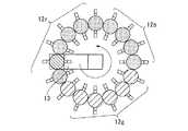
回転光学系11には、図2に示すように、複数のR(赤)色のLED12r(12r−1、12r−2、12r−3、…)、複数のG(緑)色のLED12g(12g−1、12g−2、12g−3、…)、複数のB(青)色のLED12b(12b−1、12b−2、12−3、…)が円周上に配列されている。これら円周上に配置された複数のLED12r、12g、12bに対して、回転ロッド13が設けられる。 As shown in FIG. 2, the rotating
回転ロッド13は、モータ14により回転される。回転ロッド13の回転は、回転検出センサ15により検出される。この回転検出センサ15からの回転位置検出信号は、DMD駆動制御回路3に供給されると共に、PLL回路16に供給される。PLL回路16で、基準クロックが形成される。この基準クロックがタイミング生成回路6に供給される。 The rotating
また、DMD駆動制御回路3で、回転検出センサ15からの回転位置検出信号の回転数及び位相と、入力ビデオ信号の垂直同期信号の周期及び位相とが比較され、この比較信号に基づいて、モータ駆動信号が生成される。これにより、入力ビデオ信号の垂直同期信号に同期して、所望の回転数となるように、モータ14の回転が制御される。 The DMD
モータ14が回転することにより、回転ロッド13の入射端13aが円周上に配置された複数のLED12r、12g、12b上に沿って回転する。回転ロッド13の回転により、複数のLED12r、12g、12bのうち、回転ロッド13の入射端13aの位置と対応する位置にあるものの光が選択されて取り込まれ、その光が回転ロッド13の出射端13bから導出される。 When the
回転ロッド13からの光は、逆テーパ形状のロッドである導光光学素子17に入射される。導光光学素子17の出射端から出射された光は、照明レンズ18a、18b、ミラー19、フィールドレンズ20よる照明光学系を経て、DMD素子5の微小ミラーが形成された面に照射される。 The light from the rotating
DMD素子5の表面の微少ミラーの角度は、DMD駆動信号により変えられ、光の進路が変えられる。このため、DMD素子5の反射光は、DMD駆動制御回路3からのDMD駆動信号により画素単位で変調される。このDMD駆動信号により変調を受けた光は、投射光として、投射レンズ21を介して拡大され、投射面22に投射される。これにより、投射面22には、画像が映し出される。 The angle of the minute mirror on the surface of the
2.ビデオ信号のモード判定
前述したように、本発明が適用されたプロジェクタでは、パーソナルコンピュータ等からのRGBカラービデオ信号と、NTSC方式等のカラービデオ信号を入力することができる。例えばパーソナルコンピュータからのアナログRGBビデオ信号の水平同期信号及び垂直同期信号は、その出力ビデオ信号の解像度に応じて、極性、タイミング、周波数がVESA(Video Electronics Standards Association)等で規定されている。また、パーソナルコンピュータによっては、規格外の極性やタイミングのビデオ信号を出力する場合がある。2. As described above, the projector to which the present invention is applied can input RGB color video signals from a personal computer or the like and color video signals of the NTSC system or the like. For example, the horizontal sync signal and vertical sync signal of an analog RGB video signal from a personal computer are specified by VESA (Video Electronics Standards Association) or the like in accordance with the resolution of the output video signal. Also, some personal computers may output video signals with non-standard polarity and timing.
そこで、本発明が適用されたプロジェクタでは、規格外の極性やタイミングのビデオ信号を含む各種のビデオ信号に対応できるように、DMD駆動制御回路3で、ビデオ信号処理回路2からの水平同期信号及び垂直同期信号から、現在入力されている信号の解像度及びリフレッシュレートを判別し(以下、モード判別と称する)、そのモード判別結果に応じて、各種の制御を行うようにしている。 Therefore, in the projector to which the present invention is applied, the DMD
図3は、DMD駆動制御回路3に構成されるビデオ種別検出回路の一例を示すものである。図3において、入力端子31に、ビデオ信号処理回路2からの入力ビデオ信号の垂直同期信号が供給され、入力端子32に、入力ビデオ信号の水平同期信号が供給される。入力端子33に、入力ビデオ信号のドットクロックが供給される。ここで、ドットクロックは、パネルの解像度に応じて設定される画素のクロックであり、水平同期信号からPLL回路(図示せず)で生成される。 FIG. 3 shows an example of a video type detection circuit configured in the DMD
入力端子31からの垂直同期信号は、垂直同期調整回路33に供給される。入力端子32からの水平同期信号は、水平同期調整回路34に供給される。入力端子33からのドットクロックは、分周器35に供給される。分周器35で、ドットクロックを分周してサンプリングクロックが生成される。このサンプリングクロックは、垂直同期調整回路33及び水平同期調整回路34に供給される。 The vertical synchronization signal from the
垂直同期調整回路33で、ドットクロックを分周したサンプリングクロックにより、有効期間の垂直同期信号がサンプリングされる。このサンプリング結果がCPU37に送られる。また、水平同期調整回路34で、ドットクロックを分周したクロックにより、有効期間の水平同期信号がサンプリングされる。このサンプリング結果がCPU37に送られる。 In the vertical
CPU37は、垂直同期信号及び水平同期信号のサンプリング結果を取り込み、そのHレベルとLレベルの比率から、同期信号のデューティー比を検出し、検出したデューティー比から同期信号の極性を判断する。例えば入力された同期信号が負極性であると判断された場合、CPU37は、信号を反転するよう同期調整回路34及び35を制御する。垂直同期調整回路33及び水平同期調整回路34は、CPU37からの指示に基づき、垂直及び水平同期信号を正極性にして出力する。 The
垂直同期調整回路33で調整された信号は、出力端子40から出力されると共に、垂直周期計測回路38に送られる。垂直周期計測回路38により、垂直同期信号のフロントエッジと次のフロントエッジとの間の時間を、所定の周波数のクロックでカウントすることにより求められる。この垂直同期信号のフロントエッジ間のカウント値は、CPU37に送られる。 The signal adjusted by the vertical
水平同期調整回路34で調整された信号は、出力端子41から出力されると共に、水平周期計測回路39に送られる。水平周期計測回路39により、水平同期信号のフロントエッジと次のフロントエッジとの間の時間を、所定の周波数のクロックでカウントすることにより求められる。この水平同期信号のフロントエッジ間のカウント値は、CPU37に送られる。 The signal adjusted by the horizontal
CPU37は、垂直周期計測回路38からの垂直同期信号のフロントエッジ間のカウント値及び水平周期計測回路39からの水平同期信号のフロントエッジ間のカウント値と、予め記憶してある規格値データの垂直同期信号のフロントエッジ間のカウント値及び水平同期信号のフロントエッジ間のカウント値とを比較し、適合する解像度のモードを判定する。 The
一例として、解像度XGA(1024ドット×768ライン)、リフレッシュレート60Hz、ドットクロック65MHzの同期信号が入力された場合、水平同期信号の周波数は48.5KHzなので、サンプリングクロックを分周比1の65MHzとすると、カウント値は「1340」となる。同様に水平同期信号の周波数は60Hzなのでサンプリングクロックを分周比1000の65KHzとすると、カウント値は「1083」となる。 As an example, when a synchronization signal having a resolution of XGA (1024 dots × 768 lines), a refresh rate of 60 Hz, and a dot clock of 65 MHz is input, the frequency of the horizontal synchronization signal is 48.5 KHz, so the sampling clock is set to 65 MHz with a division ratio of 1. Then, the count value becomes “1340”. Similarly, since the frequency of the horizontal synchronizing signal is 60 Hz, if the sampling clock is 65 KHz with a frequency division ratio of 1000, the count value is “1083”.
CPU37は、水平周期計測回路39からの水平同期信号のフロントエッジ間のカウント値が「1340」で、垂直周期計測回路38からの垂直同期信号のフロントエッジ間のカウント値が「1083」であれば、入力されたビデオ信号がXGAの60Hzモードであると判定することになる。なお、判定には同期信号やサンプリングクロックのジッタの影響や規格信号からのズレを考慮し、判定の範囲にマージンを持たせている。 If the count value between the front edges of the horizontal synchronizing signal from the horizontal
以上説明したように、本発明が適用されたプロジェクタでは、垂直同期信号及び水平同期信号をサンプリングし、そのHレベルとLレベルとのデューティー比から、入力ビデオ信号の極性を判断し、入力ビデオ信号が負極性の場合には、信号を反転して、正極性とするようにしている。また、垂直同期信号の周期及び水平同期信号の周期を計測して、入力ビデオ信号の形態を判断している。これにより、規格外のビデオ信号を含む各種のビデオ信号の種別を判断することができる。 As described above, in the projector to which the present invention is applied, the vertical synchronization signal and the horizontal synchronization signal are sampled, the polarity of the input video signal is determined from the duty ratio between the H level and the L level, and the input video signal When is negative, the signal is inverted to be positive. Also, the form of the input video signal is determined by measuring the period of the vertical synchronizing signal and the period of the horizontal synchronizing signal. As a result, the types of various video signals including non-standard video signals can be determined.
3.LEDの点灯制御
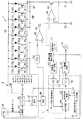
また、本発明が適用されたプロジェクタでは、前述したように、モータ14の回転を回転検出センサ15で検出し、回転検出センサ15からの回転位置検出信号からPLL回路16により基準クロックを生成し、この基準クロックによりLED点灯パルスを生成している。また、DMD駆動制御回路3で、入力ビデオ信号の同期信号に同期して、所望の回転数となるように、モータ14の回転を制御している。LEDの点灯タイミングや、モータ14の回転は、上述のモード判別結果に応じて設定される。図4は、このような制御を行うための回路の詳細を示すものである。3. LED lighting control In the projector to which the present invention is applied, as described above, the rotation of the
図4において、R色のLED12r(12r−1、12r−2、12r−3、…)、G色のLED12g(12g−1、12g−2、12g−3、…)、B色のLED12b(12b−1、12b−2、12b−3、…)は、図2に示したように、円周上に配列されている。 In FIG. 4,
LED12r(12r−1、12r−2、12r−3、…)、LED12g(12g−1、12g−2、12g−3、…)、LED12b(12b−1、12b−2、12b−3、…)に対して、各LEDをスイッチングするためのFET(Field Effect Transistor)66r(66r−1、66r−2、66r−3、…)、FET66g(66g−1、66g−2、66g−3、…)、FET66b(66b−1、66b−2、66b−3、…)が設けられる。
LED12r(12r−1、12r−2、12r−3、…)、LED12g(12g−1、12g−2、12g−3、…)、LED12b(12b−1、12b−2、12b−3、…)のアノードは、電源ライン66に接続される。LED12r(12r−1、12r−2、12r−3、…)、LED12g(12g−1、12g−2、12g−3、…)、LED12b(12b−1、12b−2、12b−3、…)のカソードは、FET66r(66r−1、66r−2、66r−3、…)、FET66g(66g−1、66g−2、66g−3、…)、FET66b(66b−1、66b−2、66b−3、…)のドレインにそれぞれ接続される。
FET66r(66r−1、66r−2、66r−3、…)、FET66g(66g−1、66g−2、66g−3、…)、FET66b(66b−1、66b−2、66b−3、…)のゲートには、デコーダ59から、点灯パルスPr(Pr−1、Pr−2、Pr−3、…)、Pg(Pg−1、Pg−2、Pg−3、…)、Pb(Pb−1、Pb−2、Pb−3、…)がそれぞれ供給される。1つおきのFET66r(66r−1、66r−3、…)、FET66g(66g−1、66g−3、…)、FET66b(66b−1、66b−3)のソースがライン67に接続され、他の1つおきのFET66r(66r−2、…)、FET66g(66g−2、…)、FET66b(66b−2、…)のソースがライン68に接続される。
ライン67には、FET69のドレインが接続される。FET69のソースが演算増幅器64の反転入力端子に接続されると共に、FET69のソースと接地間に、抵抗71が接続される。 The drain of the
ライン68には、FET70のドレインが接続される。FET70のソースが演算増幅器65の反転入力端子に接続されると共に、FET70のソースと接地間に、抵抗72が接続される。 The drain of the
PLL回路56により、回転検出センサ15の回転位置検出信号から、基準クロックが形成される。この基準クロックが分周器57を介して、カウンタ58に供給される。カウンタ58のカウント値は、デコーダ59に供給される。デコーダ59により、基準クロックのカウント値から、各LED12r(12r−1、12r−2、12r−3、…)、LED12g(12g−1、12g−2、12g−3、…)、LED12b(12b−1、12b−2、12b−3、…)の点灯を制御するための点灯パルスPr(Pr−1、Pr−2、Pr−3、…)、Pg(Pg−1、Pg−2、Pg−3、…)、Pb(Pb−1、Pb−2、Pb−3、…)が生成される。 The
また、ROM60には、予め、各色のLEDの最適な電流値のデータが格納されている。カウンタ58のカウント値に基づいて、アドレス発生回路61から、各色のLEDに対応する最適な電流値を読み出すためのアドレスが発生される。このアドレスに基づいて、ROM60から、電流値の設定データが出力される。この電流値の設定データは、D/Aコンバータ62に供給され、D/Aコンバータ62で、電流値の設定電圧に変換される。この電流値の設定電圧は、演算増幅器64及び65の非反転入力端子に供給される。 The
デコーダ59からは、順次Hレベルになる点灯パルスPr(Pr−1、Pr−2、Pr−3、…)、Pg(Pg−1、Pg−2、Pg−3、…)、Pb(Pb−1、Pb−2、Pb−3、…)が出力される。例えば、点灯パルスPr−1がHレベルになると、FET66r−1がオンする。これにより、LED12r−1に電流が流れ、LED12r−1が点灯する。 From the
このとき、LED12r−1に流れる電流は、FET69を流れる電流により決まる。演算増幅器64の非反転入力端子には、ROM60から読み出された電流値の設定データに基づく設定電圧が供給される。演算増幅器64の出力電圧はFET69のゲートに印加され、FET69のソース電圧は、演算増幅器64にフィードバックされる。したがって、FET69のゲートには電流値の設定データに基づく電圧が印加され、FET69には、所望の電流が流される。これにより、LED12r−1に所望の駆動電流を流すことができる。 At this time, the current flowing through the
次に、点灯パルスPr−2がHレベルになると、FET66r−2がオンする。これにより、LED12r−2に電流が流れ、LED12r−2が点灯する。このとき、LED12r−2に流れる電流は、FET70を流れる電流により決まる。演算増幅器65の非反転入力端子には、ROM60から読み出された電流値の設定データに基づく設定電圧が供給される。演算増幅器65の出力電圧はFET70のゲートに印加され、FET70のソース電圧は、演算増幅器65にフィードバックされる。したがって、FET70のゲートには電流値の設定データに基づく電圧が印加され、FET70には、所望の電流が流される。これにより、LED12r−2に所望の駆動電流を流すことができる。 Next, when the lighting pulse Pr-2 becomes H level, the
以下、点灯パルスPr(Pr−1、Pr−2、Pr−3、…)、Pg(Pg−1、Pg−2、Pg−3、…)、Pb(Pb−1、Pb−2、Pb−3、…)が順次Hレベルになると、FET66r(66r−1、66r−2、66r−3、…)、FET66g(66g−1、66g−2、66g−3、…)、FET66b(66b−1、66b−2、66b−3、…)がそれぞれオンし、LED12r(12r−1、12r−2、12r−3、…)、LED12g(12g−1、12g−2、12g−3、…)、LED12b(12b−1、12b−2、12b−3、…)が点灯する。 Hereinafter, the lighting pulses Pr (Pr-1, Pr-2, Pr-3, ...), Pg (Pg-1, Pg-2, Pg-3, ...), Pb (Pb-1, Pb-2, Pb-). 3,... Sequentially become H level,
なお、各LED12r(12r−1、12r−2、12r−3、…)、LED12g(12g−1、12g−2、12g−3、…)、LED12b(12b−1、12b−2、12b−3、…)の点灯時間は、DMD駆動制御回路3のCPU37からデコーダ59に送られるモード判定結果信号に応じて設定することができる。 Each
また、この例では、1つおきのFET66r(66r−1、66r−3、…)、FET66g(66g−1、66g−3、…)、FET66b(66b−1、66b−3)のソースがライン67に接続され、他の1つおきのFET66r(66r−2、…)、FET66g(66g−2、…)、FET66b(66b−2、…)のソースがライン68に接続されているので、隣り合うLEDを同時に点灯する期間を設けることができる。 In this example, every
4.モータ制御
次に、モータ制御について説明する。図4において、入力端子51には、入力ビデオ信号の垂直同期信号が供給される。入力端子51からの垂直同期信号は、分周器52を介して、位相比較回路53に供給される。また、回転検出センサ15からの回転位置検出信号は、分周器54を介して、位相比較回路53に供給される。4). Motor Control Next, motor control will be described. In FIG. 4, the
位相比較回路53で、分周器52を介された垂直同期信号の位相と、分周器54を介された回転位置検出信号の位相とが比較される。この位相比較出力は、ローパスフィルタ55を介してモータ駆動回路10に供給され、モータ駆動回路10によりモータ14が回転される。 In the
モータ14の回転は、回転検出センサ15で検出される。この回路検出信号は、分周器54を介して、位相比較回路53に帰還される。また、回転検出センサ15の回転位置検出信号は、回転数検出回路50に供給される。回転数検出回路50で、モータ14の回転数が検出される。この回転数は、CPU37に供給され、CPU37で、目標回転数と比較される。これにより、モータ14の回転は、入力ビデオ信号の垂直同期信号に同期した所望の回転数となるように制御される。そして、分周器52及び分周器54の分周比を適宜設定することで、垂直同期信号の位相と、モータ14の回転の位相との関係を設定することができる。 The rotation of the
5.各モードに応じた点灯制御
本発明が適用されたプロジェクタでは、水平周波数や垂直周波数が異なる複数のビデオ信号を入力することができる。前述したモード判別結果に基づき、以下のようにLEDの発光が制御される。5. Lighting control according to each mode In the projector to which the present invention is applied, a plurality of video signals having different horizontal frequencies and vertical frequencies can be input. Based on the mode discrimination result described above, the light emission of the LED is controlled as follows.
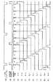
図5は、入力ビデオ信号の垂直周波数fvが(fv<62.5Hz)の場合の各LEDの発光タイミングの一例を示すものである。なお、ここでは、説明の簡略化のために、RGBのLED12r、12g、12bは、各3個で、合計9個のLEDを使用するものとし、各色のLED12r、12g、12bの発光時間は等しいものとする。 FIG. 5 shows an example of the light emission timing of each LED when the vertical frequency fv of the input video signal is (fv <62.5 Hz). Here, for simplification of explanation, it is assumed that the
前述したように、本発明が適用されたプロジェクタでは、また、垂直同期信号の周期及び水平同期信号の周期を計測して、入力ビデオ信号の形態を判断し、モード判別を行っている。 As described above, in the projector to which the present invention is applied, the period of the vertical synchronizing signal and the period of the horizontal synchronizing signal are measured, the form of the input video signal is determined, and the mode is determined.
このモード判別の結果、入力ビデオ信号の垂直周波数fvが(fv=60Hz)と判断された場合には、図5(B)に示すように、入力ビデオ信号(図5(A))の2垂直周期の期間に、モータ14が4回転するように、モータ14の回転が制御される。そして、タイミング生成回路6において、図5(D)〜図5(L)に示すように、2垂直周期の期間(33.3mS)に、各LED12r−1〜12r−3、LED12g−1〜12g−3、LED12b−1〜12b−3が、4回繰り返して順次点灯するように、点灯パルスPr−1〜Pr3、Pg−1〜Pg3、Pb−1〜Pb3が生成される。 If it is determined that the vertical frequency fv of the input video signal is (fv = 60 Hz) as a result of this mode discrimination, as shown in FIG. 5B, two vertical directions of the input video signal (FIG. 5A) are obtained. The rotation of the
この点灯パルスPr−1〜Pr3、Pg−1〜Pg3、Pb−1〜Pb3により、各LED12r−1〜12r−3、LED12g−1〜12g−3、LED12b−1〜12b−3に接続されたスイッチング用FET66r−1〜66r−3、66g−1〜66g−3、66b−1〜66b−3がオンされ、各LED12r−1〜12r−3、LED12g−1〜12g−3、LED12b−1〜12b−3が順次点灯する。 The lighting pulses Pr-1 to Pr3, Pg-1 to Pg3, and Pb-1 to Pb3 are connected to the
ここで、各LED12r−1〜12r−3、LED12g−1〜12g−3、LED12b−1〜12b−3の点灯時間は、点灯パルスPr−1〜Pr3、Pg−1〜Pg3、Pb−1〜Pb3のパルス幅に依存する。 Here, the lighting times of the
例えば点灯パルスPr−1〜Pr3、Pg−1〜Pg3、Pb−1〜Pb3のパルス幅を0.85mSとした場合、2垂直周期の期間に9個のLEDが各4回点灯するので、LEDの2垂直周期での累積点灯時間は
0.85×9×4=30.6mS
となる。For example, when the pulse widths of the lighting pulses Pr-1 to Pr3, Pg-1 to Pg3, and Pb-1 to Pb3 are set to 0.85 mS, nine LEDs are lit four times each in the period of 2 vertical cycles, The cumulative lighting time in two vertical cycles is 0.85 × 9 × 4 = 30.6 mS
It becomes.
実際には、図6に示すように、1つのLEDの発光期間は更に数十分割(図10では20分割)した時間でパルス点灯される。つまり、図6(A)に示すように、fv=60Hzの垂直期間に、図6(B)に示すように、点灯パルスPr−1,Pr−2、…が設定される。図6(C)に示すように、1回の点灯パルスの期間に、カウンタのクロックは20回カウントされる。各点灯パルスの発光期間の先頭のタイミングで、図6(E)〜図6(J)に示すように、先頭を示すパルスが出力される。 Actually, as shown in FIG. 6, the light emission period of one LED is pulse-lit at a time further divided by several tens of minutes (20 divisions in FIG. 10). That is, as shown in FIG. 6A, the lighting pulses Pr-1, Pr-2,... Are set in the vertical period of fv = 60 Hz as shown in FIG. As shown in FIG. 6C, the counter clock is counted 20 times during one lighting pulse. As shown in FIGS. 6E to 6J, a pulse indicating the head is output at the head timing of the light emission period of each lighting pulse.
ここで、1回転当たり、点灯パルスPr−1の期間で20回、点灯パルスPr−2の期間で20回、点灯パルスPr−3の期間で20回で、RGB総計で180回、RGB間の休止期間を各5回の点灯に相当する時間とすると、195回の点灯になるので、
1/{(1/120Hz)/195}=23.4KHz
となり、パルス点灯のカウンタクロック(図6(D))の周波数は23.4KHzになる。Here, per revolution, 20 times in the period of the lighting pulse Pr-1, 20 times in the period of the lighting pulse Pr-2, 20 times in the period of the lighting pulse Pr-3, 180 times in total of RGB, between RGB If the rest period is a time corresponding to 5 lightings each, it will be 195 lightings,
1 / {(1/120 Hz) / 195} = 23.4 KHz
Thus, the frequency of the pulse lighting counter clock (FIG. 6D) is 23.4 KHz.
同様に、図7は、入力ビデオ信号の垂直周波数fvが(fv≧62.5Hz)の場合の各LEDの発光タイミングを示すものである。 Similarly, FIG. 7 shows the light emission timing of each LED when the vertical frequency fv of the input video signal is (fv ≧ 62.5 Hz).
モード判別の結果、入力ビデオ信号の垂直周波数fvが(fv=75Hz)と判断された場合には、図7(B)に示すように、入力ビデオ信号の2垂直周期の期間に、モータ14が3回転するように、モータ14の回転が制御される。そして、タイミング生成回路6において、図7(D)〜図7(L)に示すように、2垂直周期の期間(26.6mS)に、各LED12r−1〜12r−3、LED12g−1〜12g−3、LED12b−1〜12b−3が3回繰り返して順次点灯するように、点灯パルスPr−1〜Pr3、Pg−1〜Pg3、Pb−1〜Pb3が生成される。 As a result of the mode discrimination, when the vertical frequency fv of the input video signal is determined to be (fv = 75 Hz), as shown in FIG. 7B, the
この点灯パルスPr−1〜Pr3、Pg−1〜Pg3、Pb−1〜Pb3により、各LED12r−1〜12r−3、LED12g−1〜12g−3、LED12b−1〜12b−3に接続されたスイッチング用FET66r−1〜66r−3、66g−1〜66g−3、66b−1〜66b−3がオンされ、各LED12r−1〜12r−3、LED12g−1〜12g−3、LED12b−1〜12b−3が順次点灯する。 The lighting pulses Pr-1 to Pr3, Pg-1 to Pg3, and Pb-1 to Pb3 are connected to the
この場合、モータ14は2垂直期間に3回回転するので、112.5Hzで回転することになる。例えばRGBの個々のLED12r−1〜12r−3、LED12g−1〜12g−3、LED12b−1〜12b−3のパルス幅を0.91mSとした場合、2垂直周期の期間に9個のLEDが各3回点灯するので、LEDの2垂直周期での累積点灯時間は
0.91×9×3=24.57mS
となる。In this case, since the
It becomes.
実際には、図8に示すように、1つのLEDの発光期間は更に数十分割(図10では20分割)した時間でパルス点灯される。つまり、図8(A)に示すように、fv=75Hzの垂直期間に、図8(B)に示すように、点灯パルスPr−1,Pr−2、…が設定される。図8(C)に示すように、1回の点灯パルスの期間に、カウンタのクロックは20回カウントされる。各点灯パルスの発光期間の先頭のタイミングで、図8(E)〜図6(I)に示すように、先頭を示すパルスが出力される。1回転当たり、点灯パルスPr−1の期間で20回、点灯パルスPr−2の期間で20回、点灯パルスPr−3の期間で20回で、RGB総計で180回、RGB間の休止期間を各5回の点灯に相当する時間とすると、195回の点灯になるので、
1/{(1/112.5Hz)/195}=21.9KHz
となり、パルス点灯のクロック周波数は21.9KHzになる。Actually, as shown in FIG. 8, the light emission period of one LED is pulse-lit at a time further divided by several tens of minutes (20 divisions in FIG. 10). That is, as shown in FIG. 8A, the lighting pulses Pr-1, Pr-2,... Are set in the vertical period of fv = 75 Hz as shown in FIG. As shown in FIG. 8C, the counter clock is counted 20 times during the period of one lighting pulse. As shown in FIGS. 8E to 6I, a pulse indicating the head is output at the head timing of the light emission period of each lighting pulse. Per revolution, 20 times in the period of the lighting pulse Pr-1, 20 times in the period of the lighting pulse Pr-2, 20 times in the period of the lighting pulse Pr-3, 180 times in total of RGB, a pause period between RGB If it is the time corresponding to 5 lightings each, it will be 195 lightings,
1 / {(1 / 112.5 Hz) / 195} = 21.9 KHz
Thus, the clock frequency for pulse lighting is 21.9 KHz.
なお、この例では、LEDの点灯幅を制御するのに、カウント値を固定にして、クロック周波数を変えているが、クロック周波数を固定にして、カウント値を変えるようにしても良い。 In this example, to control the lighting width of the LED, the count value is fixed and the clock frequency is changed. However, the clock value may be fixed and the count value may be changed.
このように、本発明が適用されたプロジェクタでは、入力ビデオ信号の2垂直周期の期間を単位とし、この2垂直周期の期間のLEDの発光回数及び発光時間を制御することにより、2垂直周期の期間での光源の総発光量としては略等しくなる。これにより、各種のビデオ信号が切り替えられたときにも、輝度変動が生じることがなくなる。 As described above, in the projector to which the present invention is applied, the period of two vertical periods of the input video signal is used as a unit, and the number of times of light emission and the light emission time of the LED in the period of the two vertical periods are controlled. The total light emission amount of the light source in the period is substantially equal. As a result, even when various video signals are switched, luminance fluctuation does not occur.
6.各モードに応じたモータ回転制御
前述したように、本発明が適用されたプロジェクタでは、図4に示したように、分周器52を介された入力ビデオ信号の垂直同期信号の位相と、分周器54を介された回転位置検出信号の位相とを比較し、この比較出力によりモータ14の回転速度を制御することで、モータ14を、入力ビデオ信号の垂直同期信号に同期した所望の回転数で回転させるようにしている。モードが切り替わると、これに応じて、分周器52及び分周器54が適宜設定される。LEDの発光は、上述のように、入力ビデオ信号の2垂直周期の期間を単位として、発光量が略等しくなるように発光ダイオードを制御するようにしている。モータ14の回転は、2垂直周期の期間を単位として、2垂直期間で整数回、回転されるように制御される。6). As described above, in the projector to which the present invention is applied, as shown in FIG. 4, the phase of the vertical synchronizing signal of the input video signal via the
7.モータ回転が安定していない場合の制御
ところで、モータ14を起動してから、モータ14の回転速度が入力ビデオ信号の垂直同期信号に同期した所定の速度になるまでには時間が必要である。7). Control When Motor Rotation is Unstable By the way, it takes time until the rotational speed of the
図9は、モータ14の回転速度の遷移を示すものである。図9において、時刻T0でモータ14が起動されると、図9(C)に示すように、モータ14の回転速度が徐々に上がっていく。入力ビデオ信号の垂直同期信号(図9(A))と、回転位置検出信号(図9(B))の位相とが比較され、この位相誤差に応じて、モータ14の回転が制御される。時刻T0〜T1では、モータ14の回転数は所望の回転数に達しておらず、入力ビデオ信号の垂直同期信号の位相とモータの回転の位相との位相誤差は大きく、モータ14の回転は安定していない。時刻T1になると、モータ14の回転数は所望の回転数に達し、入力ビデオ信号の垂直同期信号の位相とモータの回転の位相との位相誤差は小さくなり、モータ14は安定して回転するようになる。 FIG. 9 shows the transition of the rotational speed of the
このように、モータ14を立ち上げてから、モータ14の回転速度が安定するまでの時間(T0〜T1)では、モータ14の回転は安定していない。このように、モータ14の回転速度が安定していない間で、LEDを発光させて画像を表示させると、乱れた色の画面が表示されてしまう。 Thus, the rotation of the
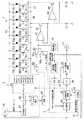
そこで、本発明が適用されたプロジェクタでは、図10に示すように、モータの回転数を検出する回転数検出回路50が設けられる。この回転数検出回路50の検出出力がCPU37に供給される。 Therefore, the projector to which the present invention is applied is provided with a rotation
CPU37は、この回転数検出回路50の検出出力から、モータ14の回転が安定したかどうかを判断し、モータ14が安定していない間では、LEDを消灯させる処理を行う。 The
すなわち、図10に示すように、CPU37は、回転数検出回路50の検出出力に基づいて、モータ14の回転が安定しているかどうかを判断し、これに応じて、デコーダ59にイネーブル信号を送る。モータ14が所定の回転数に達し、モータ14の回転が安定しているときには、CPU37からデコーダ59にイネーブル信号が送られ、各LED12r(12r−1、12r−2、12r−3、…)、LED12g(12g−1、12g−2、12g−3、…)、LED12b(12b−1、12b−2、12b−3、…)は、所定のタイミングで順次点灯する。 That is, as shown in FIG. 10, the
モータ14の回転数が所定の回転数に達していないときには、CPU37からのイネーブル信号が止められる。このときには、デコーダ59は、点灯パルスPr−1〜Pr3、Pg−1〜Pg3、Pb−1〜Pb3を全てLレベルとし、全てのLED12r(12r−1、12r−2、12r−3、…)、LED12g(12g−1、12g−2、12g−3、…)、LED12b(12b−1、12b−2、12b−3、…)が消灯される。 When the rotational speed of the
なお、この例では、CPU37からデコーダ59にイネーブル信号を送り、このイネーブル信号により、LEDの点灯/消灯を制御しているが、LEDの点灯/消灯制御は、これに限るものではない。 In this example, an enable signal is sent from the
図11は、LEDの点灯/消灯を制御の他の例を示すものである。図11において、回転数検出回路50からの検出出力がCPU37に送られる。CPU37は、CPU37は、回転数検出回路50からの検出出力に基づいて、スイッチ回路63にスイッチング信号を送る。 FIG. 11 shows another example of controlling the turning on / off of the LED. In FIG. 11, the detection output from the rotation
モータ14の回転数が所定数以上のときには、CPU37からのスイッチング信号により、スイッチ回路63が接点63a側に設定される。このときには、ROM60からの読み出された電流値の設定データに基づいて、LEDの駆動電流が設定され、各LED12r(12r−1、12r−2、12r−3、…)、LED12g(12g−1、12g−2、12g−3、…)、LED12b(12b−1、12b−2、12b−3、…)は、所定のタイミングで順次点灯する。 When the rotational speed of the
モータ14の回転数が所定値以下であると判断されると、CPU37からのスイッチング信号により、スイッチ回路63を接点63b側に設定される。スイッチ回路63が接点63b側に設定されると、演算増幅器64及び65の非反転入力端子が接地され、FET64及び65がオフする。このため、全てのLED12r(12r−1、12r−2、12r−3、…)、LED12g(12g−1、12g−2、12g−3、…)、LED12b(12b−1、12b−2、12b−3、…)消灯される。 When it is determined that the rotational speed of the
なお、スイッチ回路63を用いずに、モータ14の回転が安定していないときには、ROM60から「0」の電流値の設定データを出力させるようにしても良い。 If the rotation of the
8.ノイズ対策と省電力
ところで、ノイズ等の影響により、モータ14が所望の回転数に達しない場合がある。また、不具合により、モータ14が所望の回転数に達しない場合がある。この場合、モータ14の回転を継続すると、消費電力が無駄になる。8). Noise countermeasures and power saving By the way, the
そこで、本発明が適用されたプロジェクタでは、モータ14が所定の回転数に達しないときには、モータ14をオフするようにしている。つまり、図12に示すように、モータの回転数を検出する回転数検出回路50が設けられる。この回転数検出回路50の検出出力がCPU37に供給される。CPU37は、回転数検出回路50の検出出力から、モータ14の回転速度が所定の回転数に達しているかどうかを判断する。そして、モータ14の回転速度が所定の回転数に達していないときには、CPU37は、モータ駆動回路10にモータ停止信号を送り、モータ14の回転を停止させる。 Therefore, in the projector to which the present invention is applied, the
9.無信号時のモータ回転処理
ところで、本発明が適用されたプロジェクタでは、上述のように、分周器52を介された垂直同期信号と、分周器54を介された回転位置検出信号との位相比較出力に基づいてモータ14の回転を制御している。このため、入力信号が無信号になると、垂直同期信号が得られなくなり、モータ14が制御不能になってしまう。9. By the way, in the projector to which the present invention is applied, as described above, the vertical synchronization signal via the
入力信号が無信号のときに、モータ14の回転を停止することも考えられるが、モータを停止してしまうと、次に、ビデオ信号が入力されたときに、モータ14を所望の回転数になるまで制御するのに時間を要する。 Although it is conceivable to stop the rotation of the
そこで、本発明が適用されたプロジェクタでは、図13に示すように、例えば60Hz固定の自走垂直同期信号を生成する自走垂直同期信号発生回路73が設けられ、この自走垂直同期信号発生回路73の出力信号がスイッチ回路72の接点72bに供給される。スイッチ回路72は、通常では、接点72a側に設定される。DMD駆動制御回路3でのモード判別によって、入力ビデオ信号が無いと判断された場合には、DMD駆動制御回路3からのスイッチ制御信号により、スイッチ回路72が接点72b側に切り替えられ、この自走垂直同期信号がタイミング生成回路6及びDMD駆動制御回路3に供給される。これにより、入力信号が無い場合にも、モータ14は、例えば120Hzで安定して回転するよう制御される。また、このタイミングに基づいて、LEDの発光タイミングが設定される。 Therefore, in the projector to which the present invention is applied, as shown in FIG. 13, for example, a free-running vertical synchronization
なお、この例では、無信号時には、固定レートの自走垂直同期信号発生回路73からの自走垂直同期信号を用いるようにしているが、それまでの垂直同期信号のレートで自走垂直同期信号を発生させて、無信号時に用いるようにしても良い。 In this example, when there is no signal, the free-running vertical synchronization signal from the fixed-rate free-running vertical synchronization
10.無信号時の画像処理
また、入力ビデオ信号が無信号や途切れた場合には、LEDを点灯させてそのまま表示すると表示の乱れた画面になる。また、LEDを消灯すると、真っ暗な画面となり、OSD表示が見えなくなる。このような場合には、例えば、「入力がありません」というような意味の表示をOSDにより行い、使用者に対して、情報を知らせる必要ある。10. Image processing when there is no signal Further, when the input video signal is no signal or is interrupted, if the LED is turned on and displayed as it is, a screen with a disordered display is obtained. When the LED is turned off, the screen becomes dark and the OSD display cannot be seen. In such a case, for example, it is necessary to display the meaning such as “no input” by the OSD and inform the user of the information.
同様に、入力ビデオ信号の切り替え時に、一時的にモータ14が所定の回転数に達していない場合がある。この場合には、「しばらくお待ち下さい」というような意味の表示をOSDにより行う必要がある。更に、何らかの故障の発生により、モータ14が所定の回転数で安定して回転できなくなることが想定される。この場合には、「サービスセンターに連絡下さい」というような意味の表示をOSDにより行う必要がある。 Similarly, when the input video signal is switched, the
そこで、本発明が適用されたプロジェクタでは、入力ビデオ信号が無信号の場合又はモータ14の回転が通常と異なる場合には、DMD駆動制御回路3でマスク信号若しくは固定パターンを生成して、このマスク信号若しくは固定パターンを表示するようにしている。 Therefore, in the projector to which the present invention is applied, when the input video signal is no signal or when the rotation of the
つまり、図14に示すように、例えば、ブルーバックの固定パターンを発生する固定パターン発生回路81が設けられる。この固定パターン発生回路81からの固定パターンの信号が信号合成/切替回路82に供給される。DMD駆動制御回路3には、各種の情報を画像上に重畳表示するOSD回路37が含まれている。 That is, as shown in FIG. 14, for example, a fixed
通常の場合には、ビデオ信号処理回路2からのビデオ信号が信号合成/切替回路82を介してDMD駆動制御回路3内に送られる。入力ビデオ信号が無信号の場合又はモータ14の回転が通常と異なる場合には、固定パターン発生回路81からの固定パターンの信号が信号合成/切替回路82を介して出力され、固定パターンの信号が入力ビデオ信号に置き換えられる。これにより、ブルーバックの画像が表示され、このブルーバックの画面上に、OSD回路37による情報が表示される。 In a normal case, the video signal from the video
なお、この例では、表示するデータをブルーバックとしているが、ブルーバックに限定されるものではない。省電力目的ならば全黒表示、RGのラスターやユーザーの好みにより任意の画像を表示するようにしても良い。 In this example, the data to be displayed is a blue background, but is not limited to a blue background. For the purpose of power saving, an arbitrary image may be displayed according to all black display, RG raster or user preference.
また、本実施例ではビデオ信号処理回路2からのA/D変換後のディジタルビデオ信号に対してデータ変換を行う場合について説明したが、A/D変換前のアナログビデオ信号にマスクをかけ、表示データを出さない(全面黒表示)構成としても良い。 In this embodiment, the case where data conversion is performed on the digital video signal after A / D conversion from the video
本発明は、上述した実施形態に限定されるものではなく、本発明の要旨を逸脱しない範囲内で様々な変形や応用が可能である。 The present invention is not limited to the above-described embodiments, and various modifications and applications can be made without departing from the gist of the present invention.
本発明は、発光源としてLEDを用いたプロジェクタに広く利用することが可能である。 The present invention can be widely used for projectors using LEDs as light emitting sources.
1:入力端子、
2:ビデオ信号処理回路、
3:DMD駆動制御回路、
5:DMD素子、
6:タイミング生成回路、
7:LED駆動回路、
10:モータ駆動回路、
12r、12g、12b:LED、
11:回転光学系、
13:回転ロッド、
14:モータ、
15:回転検出センサ、
16:PLL 回路、
17:光束形状変換素子、
19:ミラー、
21:投射レンズ、
22:投射面
33:垂直同期調整回路、
34:水平同期調整回路、
35:分周器、
37:CPU、
38:垂直周期計測回路、
39:水平周期計測回路、
1: Input terminal,
2: Video signal processing circuit,
3: DMD drive control circuit,
5: DMD element,
6: Timing generation circuit,
7: LED drive circuit,
10: Motor drive circuit,
12r, 12g, 12b: LED,
11: Rotating optical system,
13: rotating rod,
14: motor,
15: rotation detection sensor,
16: PLL circuit,
17: luminous flux shape conversion element,
19: Mirror,
21: Projection lens
22: Projection surface 33: Vertical synchronization adjustment circuit,
34: Horizontal synchronization adjustment circuit,
35: Frequency divider
37: CPU,
38: Vertical period measuring circuit,
39: Horizontal period measuring circuit,
Claims (12)
Translated fromJapanese照明光を射出する複数の発光ダイオードと、
前記発光ダイオードの点灯状態を制御する点灯制御手段とを有し、
前記点灯制御手段は、前記ビデオ種別検出手段が検出したビデオ信号の種別に基づいて、前記発光ダイオードの点灯制御を行うようにした光源装置。Video type detection means for detecting the type of the input video signal;
A plurality of light emitting diodes for emitting illumination light;
Lighting control means for controlling the lighting state of the light emitting diode,
The light source device is configured to perform lighting control of the light emitting diode based on a video signal type detected by the video type detection unit.
円周上に配置された複数の発光ダイオードから出射した照明光を取り込む光学ロッドと、
前記光学ロッドを回転させるモータと、
前記モータの回転を制御する回転制御手段とを更に有し、
前記ビデオ種別検出手段の検出出力に基づいて、前記光学ロッドの回転の制御を行うようにしたことを特徴とする請求項1に記載の光源装置。The light source device is
An optical rod for capturing illumination light emitted from a plurality of light emitting diodes arranged on the circumference;
A motor for rotating the optical rod;
Rotation control means for controlling the rotation of the motor,
2. The light source device according to claim 1, wherein the rotation of the optical rod is controlled based on a detection output of the video type detection means.
前記検知手段により前記光学ロッドの回転数が所定の回転数に満たないと判断された場合には、前記複数の発光ダイオードを消灯するようにしたことを特徴とする請求項4に記載の光源装置。The rotation control means has detection means for detecting a follow-up state of the rotation of the rod with respect to the synchronization signal,
5. The light source device according to claim 4, wherein the plurality of light-emitting diodes are turned off when the detection unit determines that the rotation speed of the optical rod is less than a predetermined rotation speed. .
入力信号が無信号の場合には、前記自走垂直同期信号発生手段からの自走垂直同期信号に基づいて、前記光学ロッドを回転させるようにしたことを特徴とする請求項1に記載の光源装置。The lighting control means has a free-running vertical synchronization signal generating means for generating a free-running vertical synchronization signal at a fixed rate or a video signal rate up to that,
2. The light source according to claim 1, wherein when the input signal is no signal, the optical rod is rotated based on a free-running vertical synchronization signal from the free-running vertical synchronization signal generating means. apparatus.
照明光を射出する複数の発光ダイオードと、
前記発光ダイオードの点灯状態を制御する点灯制御手段と、
前記入力ビデオ信号に基づく駆動信号を生成する駆動信号制御手段と、
前記駆動信号制御手段からの駆動信号により駆動される空間光変調素子とを有し、
前記点灯制御手段は、前記ビデオ種別検出手段が検出したビデオ信号の種別に基づいて、前記発光ダイオードの点灯制御を行うようにした投影光学装置。Video type detection means for detecting the type of the input video signal;
A plurality of light emitting diodes for emitting illumination light;
Lighting control means for controlling the lighting state of the light emitting diode;
Drive signal control means for generating a drive signal based on the input video signal;
A spatial light modulator driven by a drive signal from the drive signal control means,
The projection optical apparatus, wherein the lighting control unit performs lighting control of the light emitting diode based on a video signal type detected by the video type detection unit.
入力ビデオ信号が無信号の場合、又は、前記検知手段により前記光学ロッドの回転数が通常と異なると判断された場合には、同期信号の状態にかかわらず、前記空間光変調素子に所定の画像を投影するようにしたことを特徴とする請求項11に記載の投影光学装置。
Having detection means for detecting the follow-up state of the rotation of the rod with respect to the synchronization signal;
When the input video signal is no signal or when the detection means determines that the rotation speed of the optical rod is different from the normal one, a predetermined image is applied to the spatial light modulator regardless of the state of the synchronization signal. The projection optical apparatus according to claim 11, wherein:
Priority Applications (2)
| Application Number | Priority Date | Filing Date | Title |
|---|---|---|---|
| JP2005168360AJP2006343500A (en) | 2005-06-08 | 2005-06-08 | Light source device and projection optical device |
| US11/445,092US20060279709A1 (en) | 2005-06-08 | 2006-06-01 | Light source device and projection optical device |
Applications Claiming Priority (1)
| Application Number | Priority Date | Filing Date | Title |
|---|---|---|---|
| JP2005168360AJP2006343500A (en) | 2005-06-08 | 2005-06-08 | Light source device and projection optical device |
Publications (1)
| Publication Number | Publication Date |
|---|---|
| JP2006343500Atrue JP2006343500A (en) | 2006-12-21 |
Family
ID=37523792
Family Applications (1)
| Application Number | Title | Priority Date | Filing Date |
|---|---|---|---|
| JP2005168360APendingJP2006343500A (en) | 2005-06-08 | 2005-06-08 | Light source device and projection optical device |
Country Status (2)
| Country | Link |
|---|---|
| US (1) | US20060279709A1 (en) |
| JP (1) | JP2006343500A (en) |
Cited By (3)
| Publication number | Priority date | Publication date | Assignee | Title |
|---|---|---|---|---|
| CN105988275A (en)* | 2015-03-20 | 2016-10-05 | 卡西欧计算机株式会社 | Projection device and projection control method suitable for projector or the like using semiconductor light-emitting element as light source |
| JP2017142514A (en)* | 2017-03-22 | 2017-08-17 | カシオ計算機株式会社 | Projection device, projection control method, and program |
| US10863058B2 (en) | 2018-11-22 | 2020-12-08 | Seiko Epson Corporation | Image processing device, display device, and image processing method |
Families Citing this family (17)
| Publication number | Priority date | Publication date | Assignee | Title |
|---|---|---|---|---|
| CN100358872C (en)* | 2003-11-14 | 2008-01-02 | 上海睿星基因技术有限公司 | The derivatives of pyridone and use thereof |
| JP4207990B2 (en)* | 2006-07-07 | 2009-01-14 | セイコーエプソン株式会社 | projector |
| US8154381B2 (en)* | 2007-12-31 | 2012-04-10 | Universal Electronics Inc. | System and method for interactive appliance control |
| KR101466119B1 (en)* | 2008-04-03 | 2014-11-27 | 삼성전자 주식회사 | Display apparatus and light control method of the same |
| US8256904B2 (en)* | 2008-05-23 | 2012-09-04 | Disney Enterprises, Inc. | Rear projected expressive head |
| CN101639613B (en)* | 2008-08-01 | 2011-03-23 | 鸿富锦精密工业(深圳)有限公司 | Projector and energy conservation control method thereof |
| CN101650514A (en)* | 2008-08-14 | 2010-02-17 | 鸿富锦精密工业(深圳)有限公司 | Projector |
| KR101039885B1 (en)* | 2009-06-22 | 2011-06-09 | 엘지이노텍 주식회사 | Color wheel light emitting unit and projection system using the same |
| US8444275B2 (en)* | 2010-08-12 | 2013-05-21 | Eastman Kodak Company | Light source control for projector with multiple pulse-width modulated light sources |
| CN103713454B (en)* | 2012-09-28 | 2016-12-07 | 深圳市绎立锐光科技开发有限公司 | Light-emitting device and relevant projecting system |
| JP2014212513A (en)* | 2013-04-01 | 2014-11-13 | パナソニック株式会社 | Projection type video display device, video projection control device, video projection control method, and video projection control program |
| CN103402060B (en)* | 2013-08-14 | 2016-08-10 | 中国科学院长春光学精密机械与物理研究所 | DMD gray scale scene player and the synchronous method of image capturing system |
| FR3074008B1 (en)* | 2017-11-20 | 2021-05-21 | Floch Albert Le | LIGHTING DEVICE FOR EASY READING. |
| CN114063374B (en)* | 2020-08-06 | 2025-01-07 | 深圳光峰科技股份有限公司 | Light source device and projection equipment |
| CN114077133B (en)* | 2020-08-12 | 2023-05-26 | 中强光电股份有限公司 | Projection device and control method thereof |
| CN112367544A (en)* | 2020-10-31 | 2021-02-12 | 上海凝汐智能科技发展有限公司 | Control system and method for compensating projection distance of projector and laser television |
| DE102021002972B4 (en) | 2021-06-10 | 2023-01-26 | Systamatec GmbH | Compact and closed device for illuminating light-optical systems using circularly moving LEDs and included lens system |
Citations (6)
| Publication number | Priority date | Publication date | Assignee | Title |
|---|---|---|---|---|
| JPH10326080A (en)* | 1997-03-24 | 1998-12-08 | Sony Corp | Video display device and method |
| JP2003279899A (en)* | 2002-03-19 | 2003-10-02 | Olympus Optical Co Ltd | Polarized light source, image display device and polarized light illuminator |
| JP2003280607A (en)* | 2002-03-25 | 2003-10-02 | Olympus Optical Co Ltd | Color video display device |
| JP2003346503A (en)* | 2002-05-24 | 2003-12-05 | Olympus Optical Co Ltd | Lighting system, photographing device using the same, and projector device |
| JP2004126144A (en)* | 2002-10-01 | 2004-04-22 | Olympus Corp | Projection display device |
| JP2004199024A (en)* | 2002-10-21 | 2004-07-15 | Olympus Corp | Illumination apparatus and image projection apparatus |
Family Cites Families (25)
| Publication number | Priority date | Publication date | Assignee | Title |
|---|---|---|---|---|
| US5754250A (en)* | 1992-02-18 | 1998-05-19 | Cooper; J. Carl | Synchronizing signal separating apparatus and method |
| JP3118503B2 (en)* | 1996-07-08 | 2000-12-18 | シーシーエス株式会社 | Lighting equipment |
| TW383508B (en)* | 1996-07-29 | 2000-03-01 | Nichia Kagaku Kogyo Kk | Light emitting device and display |
| US5790096A (en)* | 1996-09-03 | 1998-08-04 | Allus Technology Corporation | Automated flat panel display control system for accomodating broad range of video types and formats |
| DE19922176C2 (en)* | 1999-05-12 | 2001-11-15 | Osram Opto Semiconductors Gmbh | Surface-mounted LED multiple arrangement and its use in a lighting device |
| US6690428B1 (en)* | 1999-09-13 | 2004-02-10 | Nvision, Inc. | Method and apparatus for embedding digital audio data in a serial digital video data stream |
| JP2001091463A (en)* | 1999-09-22 | 2001-04-06 | Tosoh Corp | Scanner-type fluorescence detector using a small excitation light source |
| US6224216B1 (en)* | 2000-02-18 | 2001-05-01 | Infocus Corporation | System and method employing LED light sources for a projection display |
| JP3820891B2 (en)* | 2001-02-07 | 2006-09-13 | セイコーエプソン株式会社 | Image display device |
| FR2831382B1 (en)* | 2001-10-19 | 2008-12-26 | Valeo Vision | ELECTROLUMINESCENT DIODE LIGHTING OR SIGNALING DEVICE |
| AU2003215117A1 (en)* | 2002-02-09 | 2003-09-04 | Display Science, Inc. | Flexible video displays and their manufacture |
| US7289090B2 (en)* | 2003-12-10 | 2007-10-30 | Texas Instruments Incorporated | Pulsed LED scan-ring array for boosting display system lumens |
| JP2005183470A (en)* | 2003-12-16 | 2005-07-07 | Olympus Corp | Illumination apparatus and image projection apparatus using the same |
| JP2005189653A (en)* | 2003-12-26 | 2005-07-14 | Olympus Corp | Image projector |
| JP4138677B2 (en)* | 2004-02-18 | 2008-08-27 | セイコーエプソン株式会社 | Display device, display method, and projection display device |
| JP2005257790A (en)* | 2004-03-09 | 2005-09-22 | Olympus Corp | Illumination apparatus and image projection apparatus using the same |
| US20050231978A1 (en)* | 2004-03-23 | 2005-10-20 | Kvenvold Anthony M | High efficiency low power LED backlighting system for liquid crystal display |
| JP2005316406A (en)* | 2004-03-30 | 2005-11-10 | Sanyo Electric Co Ltd | Optical member, illumination apparatus and projection-type image display apparatus |
| JP4121477B2 (en)* | 2004-03-31 | 2008-07-23 | 三洋電機株式会社 | Illumination device and projection display device |
| JP2005353816A (en)* | 2004-06-10 | 2005-12-22 | Olympus Corp | LIGHT EMITTING DEVICE, LIGHT EMITTING DEVICE MANUFACTURING METHOD, LIGHTING DEVICE USING LIGHT EMITTING DEVICE, AND PROJECTOR |
| JP2006040861A (en)* | 2004-06-25 | 2006-02-09 | Olympus Corp | Lighting device, lighting apparatus and image projection apparatus |
| JP4823493B2 (en)* | 2004-08-09 | 2011-11-24 | オリンパス株式会社 | Light guide device, illumination device, spatial modulation unit, and image projection device |
| JP2006184567A (en)* | 2004-12-27 | 2006-07-13 | Toshiba Corp | Projection image display device and brightness adjustment method thereof |
| US7364306B2 (en)* | 2005-06-20 | 2008-04-29 | Digital Display Innovations, Llc | Field sequential light source modulation for a digital display system |
| US7506985B2 (en)* | 2005-10-26 | 2009-03-24 | Hewlett-Packard Development Company, L.P. | Projection light source having multiple light emitting diodes |
- 2005
- 2005-06-08JPJP2005168360Apatent/JP2006343500A/enactivePending
- 2006
- 2006-06-01USUS11/445,092patent/US20060279709A1/ennot_activeAbandoned
Patent Citations (6)
| Publication number | Priority date | Publication date | Assignee | Title |
|---|---|---|---|---|
| JPH10326080A (en)* | 1997-03-24 | 1998-12-08 | Sony Corp | Video display device and method |
| JP2003279899A (en)* | 2002-03-19 | 2003-10-02 | Olympus Optical Co Ltd | Polarized light source, image display device and polarized light illuminator |
| JP2003280607A (en)* | 2002-03-25 | 2003-10-02 | Olympus Optical Co Ltd | Color video display device |
| JP2003346503A (en)* | 2002-05-24 | 2003-12-05 | Olympus Optical Co Ltd | Lighting system, photographing device using the same, and projector device |
| JP2004126144A (en)* | 2002-10-01 | 2004-04-22 | Olympus Corp | Projection display device |
| JP2004199024A (en)* | 2002-10-21 | 2004-07-15 | Olympus Corp | Illumination apparatus and image projection apparatus |
Cited By (5)
| Publication number | Priority date | Publication date | Assignee | Title |
|---|---|---|---|---|
| CN105988275A (en)* | 2015-03-20 | 2016-10-05 | 卡西欧计算机株式会社 | Projection device and projection control method suitable for projector or the like using semiconductor light-emitting element as light source |
| JP2016177192A (en)* | 2015-03-20 | 2016-10-06 | カシオ計算機株式会社 | Projection apparatus, projection control method, and program |
| CN105988275B (en)* | 2015-03-20 | 2018-01-12 | 卡西欧计算机株式会社 | Projection arrangement and method for controlling projection |
| JP2017142514A (en)* | 2017-03-22 | 2017-08-17 | カシオ計算機株式会社 | Projection device, projection control method, and program |
| US10863058B2 (en) | 2018-11-22 | 2020-12-08 | Seiko Epson Corporation | Image processing device, display device, and image processing method |
Also Published As
| Publication number | Publication date |
|---|---|
| US20060279709A1 (en) | 2006-12-14 |
Similar Documents
| Publication | Publication Date | Title |
|---|---|---|
| JP2006343500A (en) | Light source device and projection optical device | |
| US7753554B2 (en) | Light source apparatus | |
| US7083284B2 (en) | Method and apparatus for sequencing light emitting devices in projection systems | |
| CN100576925C (en) | Image projection device and method for adjusting white balance | |
| KR101477942B1 (en) | Projector | |
| JP3983950B2 (en) | Projection display | |
| JP2006349731A (en) | Image projector | |
| US7841723B2 (en) | Projector using lamp, method and program for controlling discharge lamp light source | |
| CN100533257C (en) | Projection Image Display | |
| JP4752514B2 (en) | Projection apparatus and projection method | |
| US7852329B2 (en) | Image display apparatus | |
| JP5016607B2 (en) | LED driving device, lighting device, and display device | |
| JP5446721B2 (en) | Discharge lamp lighting device and projection-type image display device | |
| JP2007086778A (en) | Display device | |
| CN109561289B (en) | Image generation device for adjustment, image generation method for adjustment, and storage medium | |
| JP4810941B2 (en) | projector | |
| JP5257105B2 (en) | Discharge lamp lighting device and projection-type image display device | |
| US20120133896A1 (en) | Projection-type Image Display Device | |
| JP4707646B2 (en) | projector | |
| US7452085B2 (en) | Dynamically adjustable fold-mirror assembly for projection device | |
| JP2009053452A (en) | Image projection device | |
| CN100574457C (en) | Be used to increase the system and method for image brightness | |
| US20190094665A1 (en) | Projector and method of driving projector | |
| JP4014509B2 (en) | Illumination device and projection display device | |
| JP4747524B2 (en) | projector |
Legal Events
| Date | Code | Title | Description |
|---|---|---|---|
| A621 | Written request for application examination | Free format text:JAPANESE INTERMEDIATE CODE: A621 Effective date:20080507 | |
| A131 | Notification of reasons for refusal | Free format text:JAPANESE INTERMEDIATE CODE: A131 Effective date:20110315 | |
| A02 | Decision of refusal | Free format text:JAPANESE INTERMEDIATE CODE: A02 Effective date:20110712 |