JP2006343058A - Water heater - Google Patents
Water heaterDownload PDFInfo
- Publication number
- JP2006343058A JP2006343058AJP2005170642AJP2005170642AJP2006343058AJP 2006343058 AJP2006343058 AJP 2006343058AJP 2005170642 AJP2005170642 AJP 2005170642AJP 2005170642 AJP2005170642 AJP 2005170642AJP 2006343058 AJP2006343058 AJP 2006343058A
- Authority
- JP
- Japan
- Prior art keywords
- hot water
- temperature
- heat
- water tank
- compressor
- Prior art date
- Legal status (The legal status is an assumption and is not a legal conclusion. Google has not performed a legal analysis and makes no representation as to the accuracy of the status listed.)
- Pending
Links
Images


Classifications
- Y—GENERAL TAGGING OF NEW TECHNOLOGICAL DEVELOPMENTS; GENERAL TAGGING OF CROSS-SECTIONAL TECHNOLOGIES SPANNING OVER SEVERAL SECTIONS OF THE IPC; TECHNICAL SUBJECTS COVERED BY FORMER USPC CROSS-REFERENCE ART COLLECTIONS [XRACs] AND DIGESTS
- Y02—TECHNOLOGIES OR APPLICATIONS FOR MITIGATION OR ADAPTATION AGAINST CLIMATE CHANGE
- Y02B—CLIMATE CHANGE MITIGATION TECHNOLOGIES RELATED TO BUILDINGS, e.g. HOUSING, HOUSE APPLIANCES OR RELATED END-USER APPLICATIONS
- Y02B30/00—Energy efficient heating, ventilation or air conditioning [HVAC]
- Y02B30/12—Hot water central heating systems using heat pumps
Landscapes
- Steam Or Hot-Water Central Heating Systems (AREA)
- Heat-Pump Type And Storage Water Heaters (AREA)
Abstract
Translated fromJapaneseDescription
Translated fromJapanese本発明は、給湯装置に関するものである。 The present invention relates to a hot water supply apparatus.
従来この種の給湯装置では、貯湯槽の比較的上部に設けられた温度検知手段によりタンク上部の湯温を検出し、検出された温度が所定温度以下になるとヒートポンプ回路により沸き増しを行うことで、湯量を確保していた。 Conventionally, in this type of hot water supply device, the temperature detection means provided at the relatively upper part of the hot water tank detects the hot water temperature at the upper part of the tank, and when the detected temperature falls below a predetermined temperature, the heat pump circuit raises the boiling point. The amount of hot water was secured.
図7は、特許文献1に記載された従来の給湯装置を示すものである。図7に示すように、圧縮機1を備えたヒートポンプ回路と、貯湯槽2、循環ポンプ3からなる給湯回路と、貯湯槽上部に備えられ湯温を検知する貯湯槽上部温度検知手段4と、水−冷媒熱交換器5により加熱され、貯湯槽上部に流入する湯温を検知する上部流入温度検知手段6により構成されている。貯湯槽上部温度検知手段4により検出された湯温が所定の温度を下回ると、圧縮機1の回転数を最大にして沸き増し運転を開始する。このとき、貯湯槽上部温度検知手段4により検知された貯湯層2の上部温度と、水−冷媒熱交換器5を流れる流体の出口温度が等しくなるように、上部流入温度検知手段6が検知して、循環ポンプ3の回転数を制御する。よって、残湯温度と同じ湯温かつ最大の加熱能力で追焚きを行うことができるため、出湯時の湯温変化がなく湯の利便性が向上させることができる。
しかしながら、上記従来の構成ではヒートポンプ給湯器に床暖房や浴室乾燥機などの放熱手段が接続された場合には、放熱手段に放熱することにより中温水が大量に生成され、貯湯槽に混合層が形成され、さらにはその混合層の温度に合わせて沸き上げを行う可能性もあるため沸き上げ温度自体が下がってしまい、必要湯量を十分に確保できないということが考えられた。 However, in the above-described conventional configuration, when heat radiating means such as floor heating or bathroom dryer is connected to the heat pump water heater, a large amount of medium-temperature water is generated by radiating heat to the heat radiating means, and the hot water tank has a mixed layer. It is considered that the boiling temperature itself is lowered due to the formation and further boiling according to the temperature of the mixed layer, and the required amount of hot water cannot be secured sufficiently.
また、放熱手段における負荷が大きい場合やふろへの湯張り等で大量に給湯される場合等、貯湯槽上部に設けられた温度検出手段により沸き増し運転の開始を制御しているため、特に外気温が低くヒートポンプによる加熱能力が比較的小さい条件において、十分に使用熱量を賄うことができず、貯湯槽内の湯量が徐々に減少し、放熱手段の運転を停止せざるを得ない可能性もあった。 In addition, when the load on the heat dissipating means is large or when a large amount of hot water is supplied by filling the bath, etc., the temperature detection means provided at the upper part of the hot water tank controls the start of the reheating operation. Under conditions where the temperature is low and the heating capacity of the heat pump is relatively small, the amount of heat used cannot be sufficiently covered, the amount of hot water in the hot water tank gradually decreases, and the operation of the heat dissipation means may have to be stopped. there were.
さらにはヒートポンプへの入水温度(水−冷媒熱交の水入口温度)が中温水となり、ヒートポンプ効率の比較的低い条件での運転を継続しなければならない状況も考えられた。 Furthermore, the temperature at which water enters the heat pump (water inlet temperature of water-refrigerant heat exchange) becomes medium-temperature water, and it has been considered that the operation must be continued under relatively low heat pump efficiency.
前記従来の課題を解決するために、本発明の給湯装置は、貯湯槽と、圧縮機を備えるヒートポンプ回路と、前記貯湯槽の上部から出湯して熱交換器を介して前記貯湯槽に戻す1次側循環回路と、前記熱交換器を介して放熱手段に接続する2次側循環回路と、1次側循環回路に設けられた循環ポンプと、貯湯槽の下部に設けられた貯湯槽下部温度検知手段とを備え、前記循環ポンプの動作中に、前記貯湯槽下部温度検知手段による温度から算出した温度変化率に応じて圧縮機を制御するものである。 In order to solve the conventional problems, a hot water supply apparatus of the present invention includes a hot water storage tank, a heat pump circuit including a compressor, and hot water discharged from an upper part of the hot water tank and returned to the hot water tank via a heat exchanger. A secondary circulation circuit, a secondary circulation circuit connected to the heat dissipation means via the heat exchanger, a circulation pump provided in the primary circulation circuit, and a hot water tank lower temperature provided in a lower part of the hot water tank Detecting means, and controlling the compressor according to the temperature change rate calculated from the temperature by the hot water tank lower temperature detecting means during operation of the circulating pump.
これにより、放熱手段との熱交換により生成された中温水による貯湯槽の温度変化を推定することができ、かつ今後の使用湯量を推定することで、適切なタイミング、つまり後
に湯切れにならないように前もって、かつヒートポンプ効率のよい入水温度(水−冷媒熱交の水入口側温度)で必要湯量を沸き増しすることができるため、湯切れや放熱手段の運転の停止といった使用者の不便を防ぐことができる。As a result, it is possible to estimate the temperature change of the hot water storage tank due to the medium temperature water generated by heat exchange with the heat radiating means, and to estimate the amount of hot water used in the future, so that the hot water will not run out later. The required amount of hot water can be increased in advance at the water inlet temperature (water inlet side temperature of water-refrigerant heat exchange) with good heat pump efficiency, thus preventing inconvenience for the user such as running out of hot water or stopping the operation of the heat dissipation means. be able to.
本発明の給湯装置は、放熱手段が接続される等、放熱負荷が大きい場合でも、あらかじめ湯切れのないように沸き増しすることができ、かつ効率よい条件でヒートポンプを運転することができる。 The hot water supply apparatus of the present invention can be heated up in advance so as not to run out of hot water even when a heat radiation load is large, such as when a heat radiating means is connected, and the heat pump can be operated under efficient conditions.
第1の発明は、貯湯槽と、圧縮機を備えるヒートポンプ回路と、前記貯湯槽の上部から出湯して熱交換器を介して前記貯湯槽に戻す1次側循環回路と、前記熱交換器を介して放熱手段に接続する2次側循環回路と、1次側循環回路に設けられた循環ポンプと、貯湯槽の下部に設けられた貯湯槽下部温度検知手段とを備え、前記循環ポンプの動作中に、前記貯湯槽下部温度検知手段による温度から算出した温度変化率に応じて圧縮機を制御する給湯装置である。 A first aspect of the invention is a hot water storage tank, a heat pump circuit including a compressor, a primary circulation circuit that discharges hot water from an upper portion of the hot water tank and returns the hot water tank to the hot water tank via a heat exchanger, and the heat exchanger. A secondary circulation circuit connected to the heat dissipation means, a circulation pump provided in the primary circulation circuit, and a hot water tank lower temperature detection means provided in the lower part of the hot water tank, and the operation of the circulation pump In the hot water supply apparatus, the compressor is controlled in accordance with the temperature change rate calculated from the temperature by the hot water tank lower temperature detecting means.
これによって、放熱手段との熱交換により生成された中温水による貯湯槽の温度変化を推定することができ、かつ今後の使用湯量を推定することで、適切なタイミング、つまり後に湯切れにならないように前もって、かつヒートポンプ効率のよい入水温度(水−冷媒熱交の水入口側温度)で必要湯量を沸き増しすることができるため、湯切れや放熱手段の運転の停止といった使用者の不便を防ぐことができる。 As a result, it is possible to estimate the temperature change of the hot water storage tank due to the medium temperature water generated by heat exchange with the heat radiating means, and to estimate the amount of hot water used in the future, so that the hot water will not run out later. The required amount of hot water can be increased in advance at the incoming water temperature (water inlet side temperature of water-refrigerant heat exchange) with good heat pump efficiency, thus preventing inconvenience for the user such as running out of hot water or stopping the operation of the heat dissipation means. be able to.
第2の発明は、熱交換器から貯湯槽へ流入する温水温度を検知する流入温度検知手段を備え、循環ポンプの動作中に、温度検知手段により検知される温度変化率と、かつ前記流入温度検知手段による検知温度に応じて圧縮機を制御する請求項1記載の給湯装置である。 The second invention comprises inflow temperature detecting means for detecting the temperature of hot water flowing into the hot water tank from the heat exchanger, the temperature change rate detected by the temperature detecting means during the operation of the circulation pump, and the inflow temperature. The hot water supply apparatus according to
これによって、放熱手段との熱交換により生成された中温水による貯湯槽の温度変化を推定することができ、かつ今後の使用湯量を推定することで、適切なタイミング、つまり後に湯切れにならないように前もって、かつヒートポンプ効率のよい入水温度(水−冷媒熱交の水入口側温度)で必要湯量を沸き増しすることができるため、湯切れや放熱手段の運転の停止といった使用者の不便を防ぐことができる。 As a result, it is possible to estimate the temperature change of the hot water storage tank due to the medium temperature water generated by heat exchange with the heat radiating means, and to estimate the amount of hot water used in the future, so that the hot water will not run out later. The required amount of hot water can be increased in advance at the incoming water temperature (water inlet side temperature of water-refrigerant heat exchange) with good heat pump efficiency, thus preventing inconvenience for the user such as running out of hot water or stopping the operation of the heat dissipation means. be able to.
さらに、1次側循環回路の熱交換器出口側に設けられた温度検出手段により圧縮機を制御することができるので、給湯により下部から比較的低温の新鮮水が流入した場合等においても以降の貯湯槽の温度をより正確に推定することができ、同様に適切なタイミングで効率よくヒートポンプを運転することができる。 Further, since the compressor can be controlled by the temperature detecting means provided on the outlet side of the heat exchanger of the primary side circulation circuit, even when relatively cool fresh water flows from the lower part by hot water supply, etc. The temperature of the hot water tank can be estimated more accurately, and similarly, the heat pump can be efficiently operated at an appropriate timing.
第3の発明は、流入温度検知手段による検知温度が限界所定温度に達したときに圧縮機を停止する請求項2記載の給湯装置である。 A third aspect of the present invention is the hot water supply apparatus according to
これによって、流入温度検知手段による検知温度は、水−冷媒熱交換器へ流入する水温に大きく影響を及ぼす温度であるため、あらかじめ早い段階で圧縮機を停止することにより、ヒートポンプ効率の比較的低い条件での沸き上げを予防することができる。 Accordingly, the temperature detected by the inflow temperature detecting means is a temperature that greatly affects the temperature of the water flowing into the water-refrigerant heat exchanger. Therefore, the heat pump efficiency is relatively low by stopping the compressor at an early stage. Boiling up under conditions can be prevented.
第4の発明は、貯湯槽に貯えられる温水の熱量を測定する熱量測定手段を備え、循環ポンプの動作中に、温度検知手段により検出される温度変化率と、前記熱量測定手段により測定される貯湯槽の蓄熱量に応じて圧縮機を制御する請求項1記載の給湯装置である。 4th invention is equipped with the calorie | heat amount measuring means which measures the calorie | heat amount of the hot water stored in a hot water tank, and is measured by the temperature change rate detected by a temperature detection means during the operation | movement of a circulation pump, and the said calorie | heat amount measuring means. The hot water supply apparatus according to
これによって、放熱手段の連続運転や給湯等によりタンク上部にまで中温水が達する可能性がある状況においても、貯湯槽における総熱容量を算出することで、今後の使用湯量を推定したうえで適切なタイミングで効率よく必要湯量を沸き増しすることができるので、湯切れや放熱手段の運転の停止といった使用者の不便を防ぐことができる。 As a result, even if there is a possibility that medium-temperature water may reach the upper part of the tank due to continuous operation of the heat radiating means or hot water supply, etc., it is appropriate to estimate the amount of hot water used in the future by calculating the total heat capacity in the hot water tank. Since the required amount of hot water can be increased efficiently at the timing, it is possible to prevent inconvenience for the user such as running out of hot water or stopping the operation of the heat dissipating means.
第5の発明は、熱量測定手段により測定される熱量が所定値に達したとき圧縮機を停止する請求項4記載の給湯装置である。 5th invention is the hot-water supply apparatus of
これによって、必要な湯量だけを確実に沸き上げし、さらにヒートポンプ効率の比較的低い条件で不必要な沸き増しを行うことがなくなるので効率よくヒートポンプを運転することができる。 As a result, only the required amount of hot water is reliably boiled, and unnecessary heating is not performed under relatively low heat pump efficiency, so that the heat pump can be operated efficiently.
以下、本発明の実施の形態について、図面を参照しながら説明する。なお、この実施の形態によって本発明が限定されるものではない。また、実施の形態で具体的に示す温度もこれを指定するものではない。 Hereinafter, embodiments of the present invention will be described with reference to the drawings. Note that the present invention is not limited to the embodiments. Further, the temperature specifically shown in the embodiment does not specify this.
(実施の形態1)
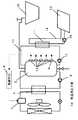
図1は、本発明の第1の実施の形態における給湯装置の図を示すものである。(Embodiment 1)
FIG. 1 shows a view of a hot water supply apparatus according to a first embodiment of the present invention.
図1において、2は水または加熱された湯を蓄えるための貯湯槽である。貯湯槽2には複数の配管が接続されており、循環ポンプ3により水−冷媒熱交換器5へ送られた水は圧縮機1を備えるヒートポンプ回路により加熱される。貯湯槽2に蓄えられた湯は、ふろ16への給湯や、放熱手段13(例えば、床暖房や浴室乾燥機など)により利用される。貯湯槽2の上部からは放熱手段13へ放熱するための1次側循環回路10が備えられており、1次側循環ポンプ12により貯湯槽2に蓄えた湯が放熱手段用熱交換器11へ送られる。熱交換器11には2次側循環回路14が接続されており、2次側循環ポンプ15により放熱手段用熱交換器11で受け取った熱を放熱手段13へと放熱することができる構成となっている。また、貯湯槽下部に配置された貯湯槽下部温度検知手段9による検知温度から算出した温度変化率をもとに制御手段8により圧縮機1を制御することができる。 In FIG. 1, 2 is a hot water storage tank for storing water or heated hot water. A plurality of pipes are connected to the
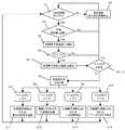
以上のように構成された給湯装置の動作・作用について、以下図2のフローチャートを用いて説明する。 The operation / action of the hot water supply apparatus configured as described above will be described below with reference to the flowchart of FIG.
まず、1次側循環ポンプが動作しているかどうかを確認する(ステップS1)。ただしこれは連続運転に限定せず、例えば床暖房では温度制御により安定時にはONとOFFの繰り返しになることもあるため、そのような間欠運転の場合にも1次側循環ポンプを動作中と判断する場合も含むものとする。1次側循環ポンプが動作中でない場合は、他制御に基づいた通常運転へと移行、またはその運転を継続する(ステップS2)。 First, it is confirmed whether the primary side circulation pump is operating (step S1). However, this is not limited to continuous operation. For example, in floor heating, temperature control may cause ON and OFF to be repeated when stable, so it is determined that the primary circulation pump is operating even in such intermittent operation. Including the case of doing. When the primary side circulation pump is not in operation, the operation is shifted to the normal operation based on the other control, or the operation is continued (step S2).
次に、1次側循環ポンプが動作中の場合、当日に湯の沸き増しが必要かどうかということを、前日までの実績や学習機能等から判断する(ステップS3)。当日の沸き増しが不必要の場合、他制御に基づいた通常運転へと移行、またはこれまでの運転を継続する(ステップS2)。沸き増し運転が必要と判断すると、貯湯槽下部温度検知手段9により貯湯槽下部温度T1を検知し(ステップS4)、T1が所定温度に達しているかどうかを判断する(ステップS4)。T1が所定温度以上(例えばT1≧70℃)のときは、他制御に基づいた通常運転へと移行、またはこれまでの運転を継続する。これは、貯湯槽2には十分な湯量があると判断することができ、さらには、この条件においてヒートポンプにより加熱運転を行おうとしても効率が低くなってしまうためである。また、T1が所定温度未満(例えばT1<70℃)のとき、貯湯槽下部温度検知手段9による検知温度から温度変化率αを算出する。ここで温度変化率αとは、ある一定時間t(例えばt=30秒)の間
の、貯湯槽下部温度検知手段9により検知される貯湯槽下部の温度変化量ΔT1と定義する。つまり、温度変化率α=ΔT1/tと表すことができ、例えば過去30秒間に貯湯槽下部温度検知手段9による検知温度T1が40℃から55℃に変化したとすると、このときの温度変化率αは、α=(55−40)/30=0.5と算出される。そこでさらに、貯湯槽下部温度T1と温度変化率αの条件を判断し(ステップS7〜ステップS10)、圧縮機の周波数の制御、または運転の停止を行う(ステップS11〜ステップS14)。Next, when the primary-side circulation pump is operating, it is determined whether or not the boiling of hot water is necessary on the day based on the results up to the previous day, the learning function, and the like (step S3). If it is not necessary to increase the boiling point on the day, the operation shifts to the normal operation based on the other control, or the operation so far is continued (step S2). When it is determined that the reheating operation is necessary, the hot water tank lower
以下そのステップについて具体例を示す。 A specific example of this step is shown below.
まず貯湯槽下部温度T1の温度が比較的低く(例えばT1<30℃)、かつその温度が上昇している場合(α≧0)、圧縮機の周波数をUP、または最大加熱能力での運転を行う。これは、今後ヒートポンプにより沸き増しを行う場合、条件から入水温度の上昇が予想される。つまり、ヒートポンプとしては効率が下がっていく方向であるため、少しでも効率のよい条件でより多くの沸き増しを済ませてしまおうというものである。 First, when the temperature of the lower part of the hot water tank T1 is relatively low (eg, T1 <30 ° C.) and the temperature is rising (α ≧ 0), the compressor frequency is increased or the operation at the maximum heating capacity is performed. Do. This is expected to increase the incoming water temperature from the condition when boiling is to be performed by a heat pump in the future. In other words, since the efficiency of the heat pump is decreasing, it will be possible to complete more boiling under a highly efficient condition.
次に、貯湯槽下部温度T1の温度が比較的低く(例えばT1<30℃)、かつその温度が下降している場合(α<0)、今後もある程度効率のよい沸きまし運転が期待できる。よって、その環境条件においてCOP(成績係数=加熱能力/消費電力)が最適になる圧縮機周波数にて運転を行う。 Next, when the temperature of the hot water storage tank lower temperature T1 is relatively low (for example, T1 <30 ° C.) and the temperature is decreasing (α <0), boiling operation with some efficiency can be expected in the future. Therefore, the operation is performed at the compressor frequency at which the COP (coefficient of performance = heating capacity / power consumption) is optimized under the environmental conditions.
また、貯湯槽下部温度T1の温度が中温域にあり(例えば30℃≦T1<70℃)、かつその温度が上昇している場合(α≧0)、圧縮機の周波数をDOWN、あるいは圧縮機の運転を一時的に停止する。これは、入水温度は中温域でヒートポンプの効率は比較的それほど高くはないものの、湯量が不十分になることが予想される場合は圧縮機の周波数をDOWNさせることで効率低下を防いだり、一定時間圧縮機の運転を停止することで温度変化率αが給湯などにより反転(α<0)してから運転できるようにする。 When the temperature of the hot water tank lower temperature T1 is in the middle temperature range (for example, 30 ° C. ≦ T1 <70 ° C.) and the temperature rises (α ≧ 0), the frequency of the compressor is DOWN or the compressor Temporarily stop driving. This is because the temperature of the incoming water is in the middle temperature range, and the efficiency of the heat pump is not so high, but if the amount of hot water is expected to be insufficient, the frequency of the compressor will be DOWN to prevent a decrease in efficiency or to be constant. By stopping the operation of the time compressor, the temperature change rate α is allowed to be reversed (α <0) by hot water supply or the like so that the operation can be performed.
最後に、貯湯槽下部温度T1が中温域にあり(例えば30℃≦T1<70℃)、かつその温度が下降している場合は(α<0)、時間をおくことで効率のよい温度域での運転ができる期待がある。そのため、とりあえずは圧縮機の周波数をDOWNさせて比較的効率の高い条件で沸き増しをしたり、またはT1が十分に下がることが期待できる場合には、T1が所定の温度未満(たとえばT1<30℃)になるまで圧縮機を停止する。 Finally, when the hot water tank lower temperature T1 is in the middle temperature range (for example, 30 ° C. ≦ T1 <70 ° C.) and the temperature is decreasing (α <0), the temperature range is efficient by putting time. There is an expectation that you can drive in. Therefore, for the time being, when the frequency of the compressor is DOWN and boiling is increased under relatively high efficiency, or when T1 can be expected to sufficiently decrease, T1 is less than a predetermined temperature (for example, T1 <30). Stop the compressor until
以上のように圧縮機の制御を行いながら、定期的に、または連続的にT1の温度を検知し、さらには温度変化率αを計算することでより効率のよい条件での沸き増し運転を行うことができる。 While controlling the compressor as described above, the temperature of T1 is detected periodically or continuously, and further, the temperature change rate α is calculated, and the boiling operation is performed under more efficient conditions. be able to.
(実施の形態2)
図2は、本発明の第2の実施の形態における給湯装置の図を示すものである。(Embodiment 2)
FIG. 2 shows a view of a hot water supply apparatus according to the second embodiment of the present invention.
図2において、1次側循環回路10上の、貯湯槽2の下部に流入する箇所に貯湯槽下部流入温度検知手段17が取り付けられ、放熱手段用熱交換器11により放熱されてできた中温水の温度(貯湯槽に流入する温度T2)を検知することができる構成となっている。他の箇所については図1と同様の構成である。 In FIG. 2, a hot water tank lower inflow
以上のように構成された給湯装置について、以下その動作、作用を説明する。 About the hot water supply apparatus comprised as mentioned above, the operation | movement and an effect | action are demonstrated below.
ステップS5までの動作に関しては実施の形態1と同様であるため省略する。ステップS5においてT1が高温水でない場合(たとえばT1<70℃)、貯湯槽下部流入温度T2を検知する(ステップS5−2)。T1は貯湯槽下部の温度に影響を及ぼす温度であり
、つまり同時にヒートポンプの運転効率に対して影響をもつため、T2の温度を含め圧縮機の制御を行うことは有効である。またT2は中温域(たとえば40℃〜60℃)で安定している場合が多く、T1のように給湯による新鮮水の流入で急激に温度変化することもあまりないのが特徴である。そこで、T2が比較的高温で安定した場合(例えばT2>50℃で60秒間安定)、タンクには今後も比較的高温の湯が流入していくことが推定される。この条件は、例えば放熱手段が床暖房であり、連続運転により温度的に安定した場合などに考えられる。そしてその場合、圧縮機を停止するか、またはこれまでの運転を継続し、効率が低い条件でのヒートポンプの運転をあらかじめ制限してしまう。また、T2が比較的低い場合(例えばT2≦50℃)には、実施の形態1同様に温度変化率αの算出(ステップ6)へと移行し、移行同様の動作を行う。Since the operations up to step S5 are the same as those in the first embodiment, a description thereof will be omitted. When T1 is not high-temperature water in step S5 (for example, T1 <70 ° C.), the hot water tank lower inflow temperature T2 is detected (step S5-2). Since T1 is a temperature that affects the temperature of the lower part of the hot water tank, that is, it affects the operating efficiency of the heat pump at the same time, it is effective to control the compressor including the temperature of T2. Further, T2 is often stable in an intermediate temperature range (for example, 40 ° C. to 60 ° C.), and is characterized in that the temperature does not change rapidly due to the inflow of fresh water by hot water supply as in T1. Therefore, when T2 is stable at a relatively high temperature (for example, stable for 60 seconds at T2> 50 ° C.), it is estimated that relatively hot water will continue to flow into the tank. This condition can be considered, for example, when the heat dissipating means is floor heating and the temperature is stabilized by continuous operation. In that case, the compressor is stopped or the operation so far is continued, and the operation of the heat pump under the condition of low efficiency is limited in advance. When T2 is relatively low (for example, T2 ≦ 50 ° C.), the process proceeds to the calculation of the temperature change rate α (step 6) as in the first embodiment, and the same operation as the transition is performed.
(実施の形態3)
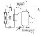
図3は、本発明の第3の実施の形態における給湯装置の図を示すものである。(Embodiment 3)
FIG. 3 shows a view of a hot water supply apparatus according to the third embodiment of the present invention.
図3において、貯湯槽2には貯湯槽下部温度検知手段9を含む熱量測定手段18が備えられ、それらにより検知された温度から貯湯槽2の蓄熱容量を算出できる構成としている。熱量測定手段18については、その検知方法は特に限定せず、例えばここではサーミスタ(温度検知手段)であるものとする。また他の箇所については、図1と同様の構成である。 In FIG. 3, the hot
以上のように構成された給湯装置について、以下その動作、作用を説明する。 About the hot water supply apparatus comprised as mentioned above, the operation | movement and an effect | action are demonstrated below.
ステップS1において1次側循環ポンプがONであると判断した場合、熱量検知手段18により貯湯槽2の蓄熱容量を測定する(ステップS1−2)。例えば、貯湯槽2の側面に設置されたサーミスタ(温度検知手段)で貯湯槽2内の湯の温度を検知し、貯湯槽2内の総蓄熱量を算出する。その総蓄熱量と前日までの実績や学習機能によるデータとを比較することで、今後沸き増しが必要かどうかをより正確に判断することができる。これにより、無駄な沸き増しをする必要がなくなる。 When it is determined in step S1 that the primary circulation pump is ON, the heat storage capacity of the
そして、ステップS4以降は実施の形態1と同様に動作するものとする。これらの動作により、必要な湯量だけを確実に沸き上げし、さらにヒートポンプ効率の比較的低い条件で不必要な沸き増しを行うことがなくなるので効率よくヒートポンプを運転することができる。 And after step S4, it shall operate | move similarly to
以上のように、本発明にかかる給湯装置は、必要な湯量だけを確実に沸き上げし、さらにヒートポンプ効率の比較的低い条件で不必要な沸き増しを行うことがなくなるので、床暖房等の放熱手段を備えたものだけでなく、ふろの追い炊き機能を備えたもの等、貯湯槽内に中温水が生成される可能性がある給湯装置に利用することができる。 As described above, the hot water supply apparatus according to the present invention reliably heats up only the necessary amount of hot water and does not perform unnecessary boiling up under relatively low heat pump efficiency. The present invention can be used for a hot water supply apparatus in which medium-temperature water is likely to be generated in a hot water storage tank, such as one provided with a means, as well as one provided with an additional cooking function.
1 圧縮機
2 貯湯槽
3 循環ポンプ
4 貯湯槽上部温度検知手段
5 水−冷媒熱交換器
6 貯湯槽上部流入温度温度検知手段
7 運転制御器
8 制御手段
9 貯湯槽下部温度検知手段
10 1次側循環回路
11 放熱手段用熱交換器
12 1次側循環ポンプ
13 放熱手段
14 2次側循環回路
15 2次側循環ポンプ
16 ふろ
17 貯湯槽下部流入温度検知手段
18 熱量測定手段DESCRIPTION OF
Claims (5)
Translated fromJapanesePriority Applications (1)
| Application Number | Priority Date | Filing Date | Title |
|---|---|---|---|
| JP2005170642AJP2006343058A (en) | 2005-06-10 | 2005-06-10 | Water heater |
Applications Claiming Priority (1)
| Application Number | Priority Date | Filing Date | Title |
|---|---|---|---|
| JP2005170642AJP2006343058A (en) | 2005-06-10 | 2005-06-10 | Water heater |
Publications (1)
| Publication Number | Publication Date |
|---|---|
| JP2006343058Atrue JP2006343058A (en) | 2006-12-21 |
Family
ID=37640148
Family Applications (1)
| Application Number | Title | Priority Date | Filing Date |
|---|---|---|---|
| JP2005170642APendingJP2006343058A (en) | 2005-06-10 | 2005-06-10 | Water heater |
Country Status (1)
| Country | Link |
|---|---|
| JP (1) | JP2006343058A (en) |
Cited By (2)
| Publication number | Priority date | Publication date | Assignee | Title |
|---|---|---|---|---|
| WO2011129248A1 (en)* | 2010-04-15 | 2011-10-20 | 三菱電機株式会社 | Controller for water heater system, program for controlling water heater system, and method for operating water heater system |
| JP2015194299A (en)* | 2014-03-31 | 2015-11-05 | ダイキン工業株式会社 | Water heater |
- 2005
- 2005-06-10JPJP2005170642Apatent/JP2006343058A/enactivePending
Cited By (6)
| Publication number | Priority date | Publication date | Assignee | Title |
|---|---|---|---|---|
| WO2011129248A1 (en)* | 2010-04-15 | 2011-10-20 | 三菱電機株式会社 | Controller for water heater system, program for controlling water heater system, and method for operating water heater system |
| CN102893097A (en)* | 2010-04-15 | 2013-01-23 | 三菱电机株式会社 | Controller for water heater system, program for controlling water heater system, and method for operating water heater system |
| JP5389257B2 (en)* | 2010-04-15 | 2014-01-15 | 三菱電機株式会社 | Hot water system controller, hot water system control program, and hot water system operation method |
| CN102893097B (en)* | 2010-04-15 | 2015-08-05 | 三菱电机株式会社 | Hot-water supply system's control device and hot-water supply system's control program and hot-water supply system's method of operation |
| US9562696B2 (en) | 2010-04-15 | 2017-02-07 | Mitsubishi Electric Corporation | Hot water supply system control apparatus and hot water supply system control program and hot water supply system operating method |
| JP2015194299A (en)* | 2014-03-31 | 2015-11-05 | ダイキン工業株式会社 | Water heater |
Similar Documents
| Publication | Publication Date | Title |
|---|---|---|
| JP4749945B2 (en) | Hot water storage heater | |
| JP4778299B2 (en) | Hot water storage type hot water supply device and method for changing standby opening of hot water mixing valve | |
| JP5919475B2 (en) | Water heater | |
| JP5401946B2 (en) | Hot water storage water heater | |
| JP4692180B2 (en) | Heat pump water heater | |
| JP3778115B2 (en) | Heat pump water heater | |
| JP2006343058A (en) | Water heater | |
| JP6734450B2 (en) | Heat pump water heater | |
| JP3851869B2 (en) | Bath memorial device | |
| JP5106567B2 (en) | Hot water storage hot water supply system | |
| JP4214991B2 (en) | Hot water storage hot water supply system | |
| JP4710511B2 (en) | Hot water storage water heater | |
| JP2004232911A (en) | Water heater | |
| JP5903654B2 (en) | Water heater | |
| JP3901108B2 (en) | Hot water storage water heater | |
| JP5948602B2 (en) | Water heater | |
| JP2004257650A (en) | Water heater | |
| JP2004170025A (en) | Electric water heater | |
| JP2005257213A (en) | Hot water storage type water heater | |
| JP3997975B2 (en) | Hot water storage water heater | |
| JP3975989B2 (en) | Water heater | |
| JP5934907B2 (en) | Water heater | |
| JP4337775B2 (en) | Water heater | |
| JP5807146B2 (en) | Water heater | |
| JP3848149B2 (en) | Thermal storage control method and apparatus |