JP2006341062A - Emergency sensor - Google Patents
Emergency sensorDownload PDFInfo
- Publication number
- JP2006341062A JP2006341062AJP2005227754AJP2005227754AJP2006341062AJP 2006341062 AJP2006341062 AJP 2006341062AJP 2005227754 AJP2005227754 AJP 2005227754AJP 2005227754 AJP2005227754 AJP 2005227754AJP 2006341062 AJP2006341062 AJP 2006341062A
- Authority
- JP
- Japan
- Prior art keywords
- acceleration
- blood pressure
- pulse
- sensing
- emergency situation
- Prior art date
- Legal status (The legal status is an assumption and is not a legal conclusion. Google has not performed a legal analysis and makes no representation as to the accuracy of the status listed.)
- Pending
Links
- 230000001133accelerationEffects0.000claimsdescription55
- 230000036772blood pressureEffects0.000claimsdescription28
- 230000005856abnormalityEffects0.000claimsdescription19
- 238000004891communicationMethods0.000claimsdescription13
- 230000002159abnormal effectEffects0.000claimsdescription8
- 238000012790confirmationMethods0.000description4
- 238000010586diagramMethods0.000description4
- 238000000034methodMethods0.000description3
- 238000009530blood pressure measurementMethods0.000description2
- 238000009532heart rate measurementMethods0.000description2
- 238000012545processingMethods0.000description2
- 230000006399behaviorEffects0.000description1
- 230000000295complement effectEffects0.000description1
- 230000000694effectsEffects0.000description1
- 238000005259measurementMethods0.000description1
Images


Classifications
- A—HUMAN NECESSITIES
- A61—MEDICAL OR VETERINARY SCIENCE; HYGIENE
- A61B—DIAGNOSIS; SURGERY; IDENTIFICATION
- A61B5/00—Measuring for diagnostic purposes; Identification of persons
- A61B5/103—Measuring devices for testing the shape, pattern, colour, size or movement of the body or parts thereof, for diagnostic purposes
- A61B5/11—Measuring movement of the entire body or parts thereof, e.g. head or hand tremor or mobility of a limb
- A61B5/1112—Global tracking of patients, e.g. by using GPS
- F—MECHANICAL ENGINEERING; LIGHTING; HEATING; WEAPONS; BLASTING
- F24—HEATING; RANGES; VENTILATING
- F24F—AIR-CONDITIONING; AIR-HUMIDIFICATION; VENTILATION; USE OF AIR CURRENTS FOR SCREENING
- F24F7/00—Ventilation
- F24F7/04—Ventilation with ducting systems, e.g. by double walls; with natural circulation
- F24F7/06—Ventilation with ducting systems, e.g. by double walls; with natural circulation with forced air circulation, e.g. by fan positioning of a ventilator in or against a conduit
- F24F7/08—Ventilation with ducting systems, e.g. by double walls; with natural circulation with forced air circulation, e.g. by fan positioning of a ventilator in or against a conduit with separate ducts for supplied and exhausted air with provisions for reversal of the input and output systems
- A—HUMAN NECESSITIES
- A61—MEDICAL OR VETERINARY SCIENCE; HYGIENE
- A61B—DIAGNOSIS; SURGERY; IDENTIFICATION
- A61B5/00—Measuring for diagnostic purposes; Identification of persons
- A61B5/02—Detecting, measuring or recording for evaluating the cardiovascular system, e.g. pulse, heart rate, blood pressure or blood flow
- A61B5/024—Measuring pulse rate or heart rate
- A—HUMAN NECESSITIES
- A61—MEDICAL OR VETERINARY SCIENCE; HYGIENE
- A61B—DIAGNOSIS; SURGERY; IDENTIFICATION
- A61B5/00—Measuring for diagnostic purposes; Identification of persons
- A61B5/103—Measuring devices for testing the shape, pattern, colour, size or movement of the body or parts thereof, for diagnostic purposes
- A61B5/11—Measuring movement of the entire body or parts thereof, e.g. head or hand tremor or mobility of a limb
- A61B5/1118—Determining activity level
- F—MECHANICAL ENGINEERING; LIGHTING; HEATING; WEAPONS; BLASTING
- F24—HEATING; RANGES; VENTILATING
- F24F—AIR-CONDITIONING; AIR-HUMIDIFICATION; VENTILATION; USE OF AIR CURRENTS FOR SCREENING
- F24F11/00—Control or safety arrangements
- F24F11/30—Control or safety arrangements for purposes related to the operation of the system, e.g. for safety or monitoring
- F—MECHANICAL ENGINEERING; LIGHTING; HEATING; WEAPONS; BLASTING
- F24—HEATING; RANGES; VENTILATING
- F24F—AIR-CONDITIONING; AIR-HUMIDIFICATION; VENTILATION; USE OF AIR CURRENTS FOR SCREENING
- F24F12/00—Use of energy recovery systems in air conditioning, ventilation or screening
- F24F12/001—Use of energy recovery systems in air conditioning, ventilation or screening with heat-exchange between supplied and exhausted air
- F24F12/006—Use of energy recovery systems in air conditioning, ventilation or screening with heat-exchange between supplied and exhausted air using an air-to-air heat exchanger
- F—MECHANICAL ENGINEERING; LIGHTING; HEATING; WEAPONS; BLASTING
- F24—HEATING; RANGES; VENTILATING
- F24F—AIR-CONDITIONING; AIR-HUMIDIFICATION; VENTILATION; USE OF AIR CURRENTS FOR SCREENING
- F24F5/00—Air-conditioning systems or apparatus not covered by F24F1/00 or F24F3/00, e.g. using solar heat or combined with household units such as an oven or water heater
- F24F5/0007—Air-conditioning systems or apparatus not covered by F24F1/00 or F24F3/00, e.g. using solar heat or combined with household units such as an oven or water heater cooling apparatus specially adapted for use in air-conditioning
- F24F5/0017—Air-conditioning systems or apparatus not covered by F24F1/00 or F24F3/00, e.g. using solar heat or combined with household units such as an oven or water heater cooling apparatus specially adapted for use in air-conditioning using cold storage bodies, e.g. ice
- F24F5/0021—Air-conditioning systems or apparatus not covered by F24F1/00 or F24F3/00, e.g. using solar heat or combined with household units such as an oven or water heater cooling apparatus specially adapted for use in air-conditioning using cold storage bodies, e.g. ice using phase change material [PCM] for storage
- A—HUMAN NECESSITIES
- A61—MEDICAL OR VETERINARY SCIENCE; HYGIENE
- A61B—DIAGNOSIS; SURGERY; IDENTIFICATION
- A61B2562/00—Details of sensors; Constructional details of sensor housings or probes; Accessories for sensors
- A61B2562/02—Details of sensors specially adapted for in-vivo measurements
- A61B2562/0219—Inertial sensors, e.g. accelerometers, gyroscopes, tilt switches
- A—HUMAN NECESSITIES
- A61—MEDICAL OR VETERINARY SCIENCE; HYGIENE
- A61B—DIAGNOSIS; SURGERY; IDENTIFICATION
- A61B5/00—Measuring for diagnostic purposes; Identification of persons
- A61B5/0002—Remote monitoring of patients using telemetry, e.g. transmission of vital signals via a communication network
- F—MECHANICAL ENGINEERING; LIGHTING; HEATING; WEAPONS; BLASTING
- F24—HEATING; RANGES; VENTILATING
- F24F—AIR-CONDITIONING; AIR-HUMIDIFICATION; VENTILATION; USE OF AIR CURRENTS FOR SCREENING
- F24F2110/00—Control inputs relating to air properties
- F24F2110/10—Temperature
- F—MECHANICAL ENGINEERING; LIGHTING; HEATING; WEAPONS; BLASTING
- F24—HEATING; RANGES; VENTILATING
- F24F—AIR-CONDITIONING; AIR-HUMIDIFICATION; VENTILATION; USE OF AIR CURRENTS FOR SCREENING
- F24F2110/00—Control inputs relating to air properties
- F24F2110/10—Temperature
- F24F2110/12—Temperature of the outside air
- F—MECHANICAL ENGINEERING; LIGHTING; HEATING; WEAPONS; BLASTING
- F24—HEATING; RANGES; VENTILATING
- F24F—AIR-CONDITIONING; AIR-HUMIDIFICATION; VENTILATION; USE OF AIR CURRENTS FOR SCREENING
- F24F2110/00—Control inputs relating to air properties
- F24F2110/20—Humidity
- Y—GENERAL TAGGING OF NEW TECHNOLOGICAL DEVELOPMENTS; GENERAL TAGGING OF CROSS-SECTIONAL TECHNOLOGIES SPANNING OVER SEVERAL SECTIONS OF THE IPC; TECHNICAL SUBJECTS COVERED BY FORMER USPC CROSS-REFERENCE ART COLLECTIONS [XRACs] AND DIGESTS
- Y02—TECHNOLOGIES OR APPLICATIONS FOR MITIGATION OR ADAPTATION AGAINST CLIMATE CHANGE
- Y02E—REDUCTION OF GREENHOUSE GAS [GHG] EMISSIONS, RELATED TO ENERGY GENERATION, TRANSMISSION OR DISTRIBUTION
- Y02E60/00—Enabling technologies; Technologies with a potential or indirect contribution to GHG emissions mitigation
- Y02E60/14—Thermal energy storage
Landscapes
- Health & Medical Sciences (AREA)
- Life Sciences & Earth Sciences (AREA)
- Engineering & Computer Science (AREA)
- General Health & Medical Sciences (AREA)
- Public Health (AREA)
- Veterinary Medicine (AREA)
- Animal Behavior & Ethology (AREA)
- Surgery (AREA)
- Molecular Biology (AREA)
- Physiology (AREA)
- Medical Informatics (AREA)
- Heart & Thoracic Surgery (AREA)
- Physics & Mathematics (AREA)
- Biophysics (AREA)
- Pathology (AREA)
- Biomedical Technology (AREA)
- Cardiology (AREA)
- Mechanical Engineering (AREA)
- Dentistry (AREA)
- Combustion & Propulsion (AREA)
- Oral & Maxillofacial Surgery (AREA)
- Chemical & Material Sciences (AREA)
- General Engineering & Computer Science (AREA)
- Radar, Positioning & Navigation (AREA)
- Sustainable Development (AREA)
- Measuring And Recording Apparatus For Diagnosis (AREA)
- Measurement Of The Respiration, Hearing Ability, Form, And Blood Characteristics Of Living Organisms (AREA)
- Measuring Pulse, Heart Rate, Blood Pressure Or Blood Flow (AREA)
- Alarm Systems (AREA)
Abstract
Description
Translated fromJapanese本発明は、加速度センサを付着した使用者の身体の動きから応急状況を感知できるようにした応急状況感知装置に関する。 The present invention relates to an emergency situation sensing device that can sense an emergency situation from a movement of a user's body to which an acceleration sensor is attached.
遠隔診療システムは、患者に付着された多様な感知センサから伝送される信号を医者が受信して処方し、患者の状態を感知して遠隔地の医者に伝送することで、医者が患者を診療及び処方できるようにするシステムである。このような遠隔診療システムには、患者に発生する可能性がある応急診療状況に対する技術が開発されてきており、その一例として、下記の特許文献1が挙げられる。
図1は、従来の携帯用自動警報機の構成を説明するための回路図である。 FIG. 1 is a circuit diagram for explaining the configuration of a conventional portable automatic alarm device.
携帯用自動警報機の本体2には、血圧、脈拍などを測定する人体状態感知装置4が連結されており、使用者の位置を確認するための位置確認装置6が連結されており、操作ボタン16が連結されており、位置確認装置6から確認された位置を外部に伝送する送信機10が連結されている。 The
制御機8は、人体状態感知装置4から入力される感知信号を解釈して、応急状況と判断される場合、位置確認装置6から確認される信号を送信機10に伝送して、位置信号を外部に伝送することで、使用者の応急状態を外部に知らせる。 The controller 8 interprets the sensing signal input from the human body
人体には血圧、脈拍の他に多様な変数があるため、応急状況が発生する場合に血圧、脈拍などが常にこのような応急状況と一致するとは見られないので、正確な応急状況を把握することは難しかった。 Since there are various variables in addition to blood pressure and pulse in the human body, when an emergency situation occurs, blood pressure, pulse, etc. will not always match such an emergency situation, so grasp the exact emergency situation That was difficult.
尚、従来の人体状態感知装置は、周期的または間欠的に人体の応急状況を感知するもので、実時間では行われなかった。 The conventional human body state sensing device senses an emergency situation of a human body periodically or intermittently and is not performed in real time.
本発明は、前記の問題点を解決するためのものであって、本発明の目的は患者に応急状況が発生する場合に、血圧、脈拍のような間接的な測定因子を補完して、人体の動きによって発生する加速度を感知することで、より直接的に応急状況を把握することにある。 The present invention is for solving the above-mentioned problems, and an object of the present invention is to complement indirect measurement factors such as blood pressure and pulse when an emergency situation occurs in a patient, By detecting the acceleration generated by the movement of the vehicle, the emergency situation can be grasped more directly.
前記の目的を達成するための本発明の特徴は、着用者の人体に着用され、人体の動きによって発生する加速度を感知するための加速度感知手段と、前記着用者の血圧及び脈拍を感知するための血圧及び脈拍感知手段と、前記加速度感知手段、血圧及び脈拍感知手段から入力される加速度、血圧、脈拍を基準加速度、血圧、脈拍とそれぞれ比べて、その差が既に設定された値以上なら、加速度異常信号、血圧異常信号及び脈拍異常信号を発生する比較手段と、外部にデータを伝送するための通信手段と、前記比較手段から前記加速度異常信号が入力される時、前記血圧異常信号、前記脈拍異常信号の入力有無を判読して、前記血圧異常信号及び前記脈拍異常信号がある場合に、前記通信手段を制御して応急状況を外部に伝送するように制御する制御部と、を含むことにある。 In order to achieve the above-mentioned object, the present invention is characterized by an acceleration sensing means for sensing acceleration generated by movement of a human body, and for sensing the blood pressure and pulse of the wearer. When comparing the acceleration, blood pressure, and pulse input from the acceleration sensing means, blood pressure and pulse sensing means with the reference acceleration, blood pressure, and pulse, respectively, if the difference is equal to or greater than a preset value, Comparison means for generating an acceleration abnormality signal, a blood pressure abnormality signal and a pulse abnormality signal, a communication means for transmitting data to the outside, and when the acceleration abnormality signal is input from the comparison means, the blood pressure abnormality signal, The presence / absence of input of a pulse abnormality signal is read, and when there is the blood pressure abnormality signal and the pulse abnormality signal, the communication means is controlled to transmit the emergency situation to the outside. Lies in including a control unit, a.
尚、本発明の他の特徴は、着用者の人体に着用され、人体の動きによって発生する加速度を感知するための加速度感知手段と、前記加速度感知手段で発生する加速度値が既に設定された値を超過するかを判断するための比較手段と、前記比較手段で加速度値が既に設定された値を超過する場合に、応急状況の真偽のほどを確認し、実際の応急状況時外部に応急状況が発生したことを知らせるための通信手段と、前記比較手段及び前記通信手段を制御するための制御手段と、を含むことにある。 Another feature of the present invention is that the acceleration sensing means for sensing the acceleration generated by the movement of the human body that is worn on the wearer's human body, and the acceleration value generated by the acceleration sensing means are already set. Comparing means for determining whether or not the acceleration value exceeds the value already set by the comparing means, confirming whether the emergency situation is true or false The communication means for notifying that the situation has occurred, and the control means for controlling the comparison means and the communication means.
尚、本発明で、前記加速度センサで感知される加速度値を貯蔵するための貯蔵手段をさらに含むことが好ましい。 In the present invention, it is preferable that storage means for storing an acceleration value sensed by the acceleration sensor is further included.
尚、本発明で、前記加速度センサは前記着用者のx、y、z軸の動きに対する加速度を感知することが好ましい。 In the present invention, it is preferable that the acceleration sensor senses acceleration with respect to movement of the wearer in the x, y, and z axes.
本発明によれば、加速度センサを着用した患者の突然な動きを感知して、着用者の異常状態を外部に告知することで、患者の異常状態をより直接的且つ具体的に、迅速に外部に知らせられる効果がある。 According to the present invention, by detecting the sudden movement of a patient wearing an acceleration sensor and notifying the wearer of an abnormal state to the outside, the patient's abnormal state can be more directly and specifically externally and quickly detected. Has the effect of being informed.
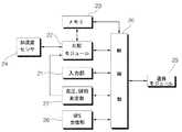
図2は、本発明の一実施例を説明するためのブロック図である。 FIG. 2 is a block diagram for explaining an embodiment of the present invention.
制御部20は、データの演算処理をし、連結された装置を制御する中央処理装置(CPU)が好ましく、制御部20は、入力部21の入力を受け付けて設定値などを変更し、システムをセットまたはリセットする。尚、制御部20は加速度センサ24、血圧、脈拍測定部27から入力される加速度、血圧、脈拍を基準値と比べて、その差が既に設定された値以上なら、加速度異常信号、血圧異常信号、脈拍異常信号を発生して制御部に入力する比較モジュール22と連結されており、比較モジュール22で比べられる加速度、血圧、脈拍は、制御部20を動作させるプログラムによりメモリ23に貯蔵される。即ち、プログラムが既に設定された値以上の加速度、血圧、脈拍だけを貯蔵するようになっている場合には、メモリ23に既に設定された値以上の加速度、血圧、脈拍を貯蔵する。このように、貯蔵された加速度データは、患者の状態把握及び治療のために判読され、利用される。 The
尚、制御部20には、外部の機器、例えば医者のコンピューターに信号を伝送するための通信モジュール25が連結されている。この時、通信モジュール25は無線、有線で外部の機器と相互交換できる装置である。 The
尚、制御部20にはGPS受信部26が連結され、本装置を着用した患者の現在位置をGPS衛星から受信して制御部20に伝送し、制御部20は患者の応急状況発生時、患者の位置を通信モジュール25を介して外部に伝送する。 A
加速度センサ24は、x、y、z軸に対する加速度をそれぞれ感知できる装置であって、加速度センサ24で感知された値は比較モジュール22に入力される。比較モジュール22は、加速度センサ24から入力される信号を増幅させ、これをデジタルデータに変換して既に設定された値と比べ、加速度値が既に設定された値より大きい場合には、制御部20に異常信号を伝送する。 The
図3は、本発明の一実施例で適用される加速度センサで測定される加速度グラフである。 FIG. 3 is an acceleration graph measured by the acceleration sensor applied in one embodiment of the present invention.
患者が倒れるなどの突然な人体の移動がある場合には、加速度の値が大きくなり、行動が一定しない場合には、陰、陽に変化する。グラフ上で5秒と24秒との間には、着用者に異常徴候が発生していることを示す。入力部21により加速度のしきい値として既に設定された値が0.5(m/sec2)なら、7秒になる瞬間に、比較モジュール22は制御部20に異常信号を伝送する。制御部20はこのような信号を入力され、着用者に異常徴候があることを外部機器に告知できる。When there is a sudden movement of the human body such as when the patient falls down, the value of acceleration increases, and when the behavior is not constant, it changes to yin and yang. Between 5 seconds and 24 seconds on the graph, the wearer is shown to have an abnormal sign. If the value already set as the threshold value of acceleration by the
図4は、本発明の制御部の動作過程を示すフローチャートである。 FIG. 4 is a flowchart showing an operation process of the control unit of the present invention.
比較モジュール22は、加速度の異常有無を判断して、異常がある場合に異常信号を制御部20に入力し(S1)、制御部20では、加速度の異常信号が入力されると比較モジュール22を制御して、血圧、脈拍を既に設定された血圧及び脈拍と比べて(S2)正常でないと判断される場合には、通信モジュール25を介して外部に患者の応急状況信号を伝送するように制御する。この時、制御部20は、GPS受信部26から現在位置を判読して、一緒に伝送させる。 The
2 本体
4 人体状態感知装置
6 位置確認装置
8 制御機
10 送信機
16 操作ボタン
20 制御部
21 入力部
22 比較モジュール
23 メモリ
24 加速度センサ
25 通信モジュール
26 GPS受信部
27 血圧、脈拍測定部
2
Claims (4)
Translated fromJapanese前記着用者の血圧及び脈拍を感知するための血圧及び脈拍感知手段と、
前記加速度感知手段、血圧及び脈拍感知手段から入力される加速度、血圧、脈拍を、基準加速度、血圧及び脈拍とそれぞれ比べて、その差が既に設定された値以上なら、加速度異常信号、血圧異常信号及び脈拍異常信号を発生する比較手段と、
外部にデータを伝送するための通信手段と、
前記比較手段から前記加速度異常信号が入力される時、前記血圧異常信号、前記脈拍異常信号の入力有無を判読して、前記血圧異常信号及び前記脈拍異常信号がある場合に、前記通信手段を制御して応急状況を外部に伝送するように制御する制御部と、
を含むことを特徴とする応急状況感知装置。An acceleration sensing means for sensing acceleration generated by movement of the human body and worn on the wearer's human body;
Blood pressure and pulse sensing means for sensing the wearer's blood pressure and pulse;
The acceleration, blood pressure, and pulse input from the acceleration sensing means, blood pressure, and pulse sensing means are compared with the reference acceleration, blood pressure, and pulse, respectively, and if the difference is equal to or greater than a preset value, an acceleration abnormality signal, blood pressure abnormality signal And a comparison means for generating an abnormal pulse signal;
A communication means for transmitting data to the outside;
When the acceleration abnormality signal is input from the comparison means, the presence / absence of the blood pressure abnormality signal and the pulse abnormality signal is read, and the communication means is controlled when the blood pressure abnormality signal and the pulse abnormality signal are present. A control unit for controlling the emergency situation to be transmitted to the outside,
An emergency situation sensing device characterized by comprising:
前記加速度感知手段で発生する加速度値が、既に設定された値を超過するかを判断するための比較手段と、
前記比較手段で加速度値が既に設定された値を超過する場合に、応急状況の真偽のほどを確認し、実際の応急状況時、外部に応急状況が発生したことを知らせるための通信手段と、
前記比較手段及び前記通信手段を制御するための制御手段と、
を含むことを特徴とする応急状況感知装置。An acceleration sensing means for sensing acceleration generated by movement of the human body and worn on the wearer's human body;
Comparison means for determining whether an acceleration value generated by the acceleration sensing means exceeds a preset value;
Communication means for confirming the authenticity of the emergency situation when the acceleration value exceeds the value already set by the comparison means, and notifying that the emergency situation has occurred to the outside during the actual emergency situation; ,
Control means for controlling the comparison means and the communication means;
An emergency situation sensing device characterized by comprising:
The emergency condition sensing device according to claim 1 or 2, wherein the acceleration sensor senses acceleration with respect to movement of the wearer in the x, y, and z axes.
Applications Claiming Priority (1)
| Application Number | Priority Date | Filing Date | Title |
|---|---|---|---|
| KR20050049459 | 2005-06-09 |
Publications (1)
| Publication Number | Publication Date |
|---|---|
| JP2006341062Atrue JP2006341062A (en) | 2006-12-21 |
Family
ID=37524978
Family Applications (1)
| Application Number | Title | Priority Date | Filing Date |
|---|---|---|---|
| JP2005227754APendingJP2006341062A (en) | 2005-06-09 | 2005-08-05 | Emergency sensor |
Country Status (3)
| Country | Link |
|---|---|
| US (1) | US20060281979A1 (en) |
| JP (1) | JP2006341062A (en) |
| KR (1) | KR20060128625A (en) |
Cited By (2)
| Publication number | Priority date | Publication date | Assignee | Title |
|---|---|---|---|---|
| JP2014518666A (en)* | 2011-04-29 | 2014-08-07 | コーニンクレッカ フィリップス エヌ ヴェ | Apparatus used for fall detector or fall detection system and method for operating the apparatus |
| RU192470U1 (en)* | 2019-07-08 | 2019-09-17 | Общество с ограниченной ответственностью "Красный Яр" | Signal processing device for remote monitoring of patients at risk |
Families Citing this family (44)
| Publication number | Priority date | Publication date | Assignee | Title |
|---|---|---|---|---|
| KR100815565B1 (en)* | 2006-08-23 | 2008-03-20 | 삼성전기주식회사 | Motion detection system and method |
| US12245852B2 (en) | 2007-06-12 | 2025-03-11 | Sotera Wireless, Inc. | Optical sensors for use in vital sign monitoring |
| US11330988B2 (en) | 2007-06-12 | 2022-05-17 | Sotera Wireless, Inc. | Body-worn system for measuring continuous non-invasive blood pressure (cNIBP) |
| US8602997B2 (en) | 2007-06-12 | 2013-12-10 | Sotera Wireless, Inc. | Body-worn system for measuring continuous non-invasive blood pressure (cNIBP) |
| WO2008154643A1 (en) | 2007-06-12 | 2008-12-18 | Triage Wireless, Inc. | Vital sign monitor for measuring blood pressure using optical, electrical, and pressure waveforms |
| US11607152B2 (en) | 2007-06-12 | 2023-03-21 | Sotera Wireless, Inc. | Optical sensors for use in vital sign monitoring |
| US10973414B2 (en) | 2009-05-20 | 2021-04-13 | Sotera Wireless, Inc. | Vital sign monitoring system featuring 3 accelerometers |
| US11896350B2 (en) | 2009-05-20 | 2024-02-13 | Sotera Wireless, Inc. | Cable system for generating signals for detecting motion and measuring vital signs |
| US8956293B2 (en) | 2009-05-20 | 2015-02-17 | Sotera Wireless, Inc. | Graphical ‘mapping system’ for continuously monitoring a patient's vital signs, motion, and location |
| KR101042684B1 (en)* | 2009-06-01 | 2011-06-20 | (주)에이치쓰리시스템 | Pressure sensor device and emergency notification device |
| US9775529B2 (en) | 2009-06-17 | 2017-10-03 | Sotera Wireless, Inc. | Body-worn pulse oximeter |
| US8545417B2 (en) | 2009-09-14 | 2013-10-01 | Sotera Wireless, Inc. | Body-worn monitor for measuring respiration rate |
| US12121364B2 (en) | 2009-09-14 | 2024-10-22 | Sotera Wireless, Inc. | Body-worn monitor for measuring respiration rate |
| US11253169B2 (en) | 2009-09-14 | 2022-02-22 | Sotera Wireless, Inc. | Body-worn monitor for measuring respiration rate |
| US8364250B2 (en) | 2009-09-15 | 2013-01-29 | Sotera Wireless, Inc. | Body-worn vital sign monitor |
| US8321004B2 (en) | 2009-09-15 | 2012-11-27 | Sotera Wireless, Inc. | Body-worn vital sign monitor |
| US12156743B2 (en) | 2009-09-15 | 2024-12-03 | Sotera Wireless, Inc. | Body-worn vital sign monitor |
| US20110066044A1 (en) | 2009-09-15 | 2011-03-17 | Jim Moon | Body-worn vital sign monitor |
| US8527038B2 (en) | 2009-09-15 | 2013-09-03 | Sotera Wireless, Inc. | Body-worn vital sign monitor |
| US10806351B2 (en) | 2009-09-15 | 2020-10-20 | Sotera Wireless, Inc. | Body-worn vital sign monitor |
| US10420476B2 (en) | 2009-09-15 | 2019-09-24 | Sotera Wireless, Inc. | Body-worn vital sign monitor |
| US20110224499A1 (en) | 2010-03-10 | 2011-09-15 | Sotera Wireless, Inc. | Body-worn vital sign monitor |
| US9339209B2 (en) | 2010-04-19 | 2016-05-17 | Sotera Wireless, Inc. | Body-worn monitor for measuring respiratory rate |
| US8979765B2 (en) | 2010-04-19 | 2015-03-17 | Sotera Wireless, Inc. | Body-worn monitor for measuring respiratory rate |
| US9173594B2 (en) | 2010-04-19 | 2015-11-03 | Sotera Wireless, Inc. | Body-worn monitor for measuring respiratory rate |
| US8747330B2 (en) | 2010-04-19 | 2014-06-10 | Sotera Wireless, Inc. | Body-worn monitor for measuring respiratory rate |
| US8888700B2 (en) | 2010-04-19 | 2014-11-18 | Sotera Wireless, Inc. | Body-worn monitor for measuring respiratory rate |
| US9173593B2 (en) | 2010-04-19 | 2015-11-03 | Sotera Wireless, Inc. | Body-worn monitor for measuring respiratory rate |
| US10722132B2 (en) | 2010-12-28 | 2020-07-28 | Sotera Wireless, Inc. | Body-worn system for continuous, noninvasive measurement of cardiac output, stroke volume, cardiac power, and blood pressure |
| SG10201601161YA (en) | 2011-02-18 | 2016-03-30 | Sotera Wireless Inc | Optical sensor for measuring physiological properties |
| SG10201601164SA (en) | 2011-02-18 | 2016-03-30 | Sotera Wireless Inc | Modular wrist-worn processor for patient monitoring |
| KR101138740B1 (en)* | 2011-07-19 | 2012-04-24 | 주식회사 소소 | Brain wave detecting headset and method for judging whether brain wave detecting headset is worn |
| EP2801079A1 (en)* | 2012-01-06 | 2014-11-12 | Koninklijke Philips N.V. | Emergency response and tracking using lighting networks |
| US9710761B2 (en) | 2013-03-15 | 2017-07-18 | Nordic Technology Group, Inc. | Method and apparatus for detection and prediction of events based on changes in behavior |
| KR102165060B1 (en)* | 2013-08-20 | 2020-10-13 | 삼성전자주식회사 | Wearable bio-signal interface and method of operation of wearable bio-signal interface |
| FI20145128A7 (en)* | 2014-02-10 | 2015-08-11 | Murata Manufacturing Co | Early acute fall risk detection |
| TWM483806U (en)* | 2014-03-04 | 2014-08-11 | Gang Zhao | Intelligent safety protection integration system carrier |
| KR102223376B1 (en)* | 2014-03-14 | 2021-03-05 | 삼성전자주식회사 | Method for Determining Data Source |
| KR101645087B1 (en)* | 2014-07-10 | 2016-08-02 | 아이리텍 잉크 | High security set using hand attached-type wearable device for iris recognition with wearing detection sensor and control method of the same set |
| US10129384B2 (en)* | 2014-09-29 | 2018-11-13 | Nordic Technology Group Inc. | Automatic device configuration for event detection |
| CN105806396A (en)* | 2014-12-31 | 2016-07-27 | 青岛中科软件股份有限公司 | Optical detection wireless sensor |
| SG10201911123XA (en) | 2016-11-30 | 2020-01-30 | Agency Science Tech & Res | A computer system for alerting emergency services |
| GB2571128B (en)* | 2018-02-19 | 2022-10-12 | Kinetik Tech Group Ltd | A wearable alarm device and a method of use thereof |
| WO2021260704A1 (en) | 2020-06-25 | 2021-12-30 | Xmetix Ltd. | Injury detection wearable system |
Family Cites Families (2)
| Publication number | Priority date | Publication date | Assignee | Title |
|---|---|---|---|---|
| US5771001A (en)* | 1996-11-18 | 1998-06-23 | Cobb; Marlon J. | Personal alarm system |
| US6160478A (en)* | 1998-10-27 | 2000-12-12 | Sarcos Lc | Wireless health monitoring system |
- 2005
- 2005-08-05JPJP2005227754Apatent/JP2006341062A/enactivePending
- 2005-10-14USUS11/251,305patent/US20060281979A1/ennot_activeAbandoned
- 2006
- 2006-03-23KRKR1020060026542Apatent/KR20060128625A/ennot_activeCeased
Cited By (3)
| Publication number | Priority date | Publication date | Assignee | Title |
|---|---|---|---|---|
| JP2014518666A (en)* | 2011-04-29 | 2014-08-07 | コーニンクレッカ フィリップス エヌ ヴェ | Apparatus used for fall detector or fall detection system and method for operating the apparatus |
| US9489815B2 (en) | 2011-04-29 | 2016-11-08 | Koninklijke Philips N.V. | Apparatus for use in a fall detector or fall detection system, and a method of operating the same |
| RU192470U1 (en)* | 2019-07-08 | 2019-09-17 | Общество с ограниченной ответственностью "Красный Яр" | Signal processing device for remote monitoring of patients at risk |
Also Published As
| Publication number | Publication date |
|---|---|
| KR20060128625A (en) | 2006-12-14 |
| US20060281979A1 (en) | 2006-12-14 |
Similar Documents
| Publication | Publication Date | Title |
|---|---|---|
| JP2006341062A (en) | Emergency sensor | |
| US11931184B2 (en) | System and method for non-intrusive health monitoring in the home | |
| WO2010050273A1 (en) | Device for detecting abnormality of auxiliary artificial heart, method for detecting abnormality of auxiliary artificial heart, and abnormality detection program | |
| KR101920537B1 (en) | smart band system for detecting emergency patients emergency patient information providing method | |
| JP6464002B2 (en) | Fall detection terminal and program | |
| GB9925021D0 (en) | Wireless health monitoring system | |
| KR20170011631A (en) | Wearable device having detection function of fall-down position and system for fall-down position detection using the same | |
| JP2002511624A (en) | Automatic control system for security equipment | |
| KR101580317B1 (en) | Pose recognition apparatus using smartphone | |
| US20110068944A1 (en) | Motion sensing remote microphone | |
| KR101921683B1 (en) | System for monitoring subject to be observed, and method for monitoring subject to be observed | |
| WO2019158954A1 (en) | A wearable alarm device and a method of use thereof | |
| KR102476015B1 (en) | Device for measuring biometric of companion animal | |
| CN107810075A (en) | Apparatus and method for protecting user in the equipment being in using at least a portion in motion | |
| US20210358284A1 (en) | Visible-light-image physiological monitoring system with thermal detecting assistance | |
| KR20020024083A (en) | Mobile health checker and method for checking health | |
| TWI507067B (en) | Portable electrical apparatus and method for detecting state of the same | |
| JP2005046468A (en) | Biological data detecting system | |
| EP4235611A2 (en) | System for monitoring the physical condition of at least one user and method for monitoring the physical condition of a user | |
| US20170180979A1 (en) | Wirelessly Triggering Smart Devices | |
| KR20230109485A (en) | A control system for wearable devices with improved reliability through double data verification | |
| KR20220118043A (en) | Smart safety clothing | |
| KR20160136631A (en) | A surveillance system | |
| EP3888070A1 (en) | A method and system for monitoring a user | |
| KR102269569B1 (en) | System for detecting falling down |
Legal Events
| Date | Code | Title | Description |
|---|---|---|---|
| A131 | Notification of reasons for refusal | Free format text:JAPANESE INTERMEDIATE CODE: A131 Effective date:20080617 | |
| A02 | Decision of refusal | Free format text:JAPANESE INTERMEDIATE CODE: A02 Effective date:20081118 |