JP2006335957A - Method for producing thermally conductive molded body and thermally conductive molded body - Google Patents
Method for producing thermally conductive molded body and thermally conductive molded bodyDownload PDFInfo
- Publication number
- JP2006335957A JP2006335957AJP2005164500AJP2005164500AJP2006335957AJP 2006335957 AJP2006335957 AJP 2006335957AJP 2005164500 AJP2005164500 AJP 2005164500AJP 2005164500 AJP2005164500 AJP 2005164500AJP 2006335957 AJP2006335957 AJP 2006335957A
- Authority
- JP
- Japan
- Prior art keywords
- thermally conductive
- molded body
- filler
- vibration
- composition
- Prior art date
- Legal status (The legal status is an assumption and is not a legal conclusion. Google has not performed a legal analysis and makes no representation as to the accuracy of the status listed.)
- Granted
Links
Images
Landscapes
- Manufacture Of Macromolecular Shaped Articles (AREA)
- Compositions Of Macromolecular Compounds (AREA)
- Cooling Or The Like Of Electrical Apparatus (AREA)
- Cooling Or The Like Of Semiconductors Or Solid State Devices (AREA)
Abstract
Translated fromJapaneseDescription
Translated fromJapanese本発明は、発熱体と放熱体との間に介在して用いられ、発熱体から放熱体への熱伝導を促進する熱伝導性成形体、及びその製造方法に関するものである。 The present invention relates to a heat conductive molded body that is used between a heat generating body and a heat radiating body and promotes heat conduction from the heat generating body to the heat radiating body, and a manufacturing method thereof.
近年、コンピュータのCPU(中央処理装置)を代表とする電子部品の高性能化に伴い、電子部品の消費電力及び発熱量は増大している。電子部品の処理能力は熱により低下する。よって、電子部品の性能を維持するために電子部品の蓄熱を回避する必要があり、電子部品の冷却が重要な課題となっている。そのため、発熱体である電子部品と、放熱体との間に介在して用いられる熱伝導性成形体には、優れた熱伝導性能が求められている。 In recent years, power consumption and heat generation of electronic components have increased with the improvement in performance of electronic components typified by computer CPUs (central processing units). The processing capacity of electronic components is reduced by heat. Therefore, it is necessary to avoid heat storage of the electronic component in order to maintain the performance of the electronic component, and cooling of the electronic component is an important issue. Therefore, the heat conductive molded object used by interposing between the electronic component which is a heat generating body, and a heat radiator is calculated | required the outstanding heat conductive performance.
特許文献1には、繊維長が10mm以下に設定された熱伝導性繊維を含有する組成物からなる熱伝導性成形体が開示されている。特許文献2には、耐熱性高分子マトリックスと、熱伝導性繊維とを備える熱伝導性成形体が開示されている。これらの熱伝導性成形体では、熱伝導性繊維を熱伝導の方向に沿って配向させることにより、熱伝導性能を高めている。 Patent Document 1 discloses a thermally conductive molded body made of a composition containing thermally conductive fibers whose fiber length is set to 10 mm or less. Patent Document 2 discloses a heat conductive molded body including a heat resistant polymer matrix and heat conductive fibers. In these thermally conductive molded bodies, the thermally conductive performance is enhanced by orienting the thermally conductive fibers along the direction of thermal conduction.
特許文献3には、シリコーンゴム基材と、熱伝導性繊維とを備える熱伝導性成形体が開示されており、熱伝導性繊維は、熱伝導性成形体の熱伝導の方向に沿って配向されている。更に、特許文献3には、熱伝導性繊維を配向させる方法として、例えば熱伝導性繊維のトウを一定方向に沈積させながら積層した後に、シリコーンゴム基材を含浸し、硬化後にトウの配向方向と垂直な面に沿って切断する方法が開示されている。 Patent Document 3 discloses a thermally conductive molded body including a silicone rubber base material and thermally conductive fibers, and the thermally conductive fibers are oriented along the direction of thermal conduction of the thermally conductive molded body. Has been. Furthermore, in Patent Document 3, as a method of orienting the heat conductive fibers, for example, after laminating while laminating tows of the heat conductive fibers in a certain direction, the silicone rubber base material is impregnated, and the tow orientation direction after curing A method of cutting along a plane perpendicular to the horizontal axis is disclosed.
特許文献4には、磁性充填材と高分子材料とを含有する組成物からなる熱伝導性成形体が開示されている。磁性充填材の一部は繊維状に形成され、繊維状の磁性充填材、即ち繊維状充填材は、熱伝導性成形体の熱伝導の方向に沿って配向されている。更に、特許文献4には、繊維状充填材を配向させる方法として、組成物中の繊維状充填材に磁場及び超音波振動を印加する方法が開示されている。
ところが、特許文献1及び2には、熱伝導性繊維を配向させる具体的な手段が開示されていない。一方、特許文献3に記載の熱伝導性繊維を配向させる方法では、作業者が手作業で熱伝導性繊維を配列させる必要があることから、熱伝導性繊維の配向が煩雑であるという問題があった。 However, Patent Documents 1 and 2 do not disclose specific means for orienting the thermally conductive fibers. On the other hand, in the method of orienting the heat conductive fibers described in Patent Document 3, it is necessary for the operator to arrange the heat conductive fibers manually, and thus there is a problem that the alignment of the heat conductive fibers is complicated. there were.
特許文献4において、繊維状充填材は、磁場及び超音波振動の印加によって容易に配向され、組成物は、磁性充填材の含有量の増加によって、熱伝導性成形体の熱伝導性能を高めることができる。しかしながら、磁性充填材の含有量の増加に伴い、組成物の粘度が高くなって繊維状充填材の配向が困難になる。また、組成物中の磁性充填材の含有量を増加させることなく熱伝導性成形体の熱伝導性能を高める方法として、繊維状充填材の繊維長を長くする方法が考えられる。しかしながら、繊維状充填材が長くなるに伴い、組成物の粘度が高くなるとともに、繊維状充填材が組成物中で絡み易くなることから、この場合にも繊維状充填材の配向が困難になる。従って、特許文献4に記載の繊維状充填材を配向させる方法では、繊維状充填材の配向の容易さと、熱伝導性成形体の熱伝導性能の更なる向上とを同時に達成することができず、優れた熱伝導性能を発揮する熱伝導性成形体の製造が困難であるという問題があった。 In Patent Document 4, the fibrous filler is easily oriented by applying a magnetic field and ultrasonic vibration, and the composition enhances the heat conduction performance of the thermally conductive molded body by increasing the content of the magnetic filler. Can do. However, as the content of the magnetic filler is increased, the viscosity of the composition becomes high, and the orientation of the fibrous filler becomes difficult. Further, as a method for improving the heat conduction performance of the thermally conductive molded body without increasing the content of the magnetic filler in the composition, a method of increasing the fiber length of the fibrous filler can be considered. However, as the fibrous filler becomes longer, the viscosity of the composition becomes higher, and the fibrous filler is easily entangled in the composition, so that the orientation of the fibrous filler is difficult in this case as well. . Therefore, in the method of orienting the fibrous filler described in Patent Document 4, it is impossible to simultaneously achieve the easy orientation of the fibrous filler and the further improvement of the heat conduction performance of the thermally conductive molded body. There has been a problem that it is difficult to produce a heat conductive molded body that exhibits excellent heat conduction performance.
本発明は、このような従来技術に存在する問題点に着目してなされたものである。その目的とするところは、優れた熱伝導性能を発揮する熱伝導性成形体を容易に製造することができる熱伝導性成形体の製造方法、及びその製造方法によって製造される熱伝導性成形体を提供することにある。 The present invention has been made paying attention to such problems existing in the prior art. The object is to provide a method for producing a thermally conductive molded body that can easily produce a thermally conductive molded body that exhibits excellent thermal conductivity, and a thermally conductive molded body produced by the production method. Is to provide.
上記の目的を達成するために、請求項1に記載の発明は、高分子マトリックスと、熱伝導性充填材とを含有する熱伝導性高分子組成物から成形される熱伝導性成形体の製造方法であって、前記熱伝導性充填材の少なくとも一部が繊維状に形成され、前記熱伝導性高分子組成物を調製する調製工程と、前記繊維状の熱伝導性充填材に磁場及び振動を印加して、繊維状の熱伝導性充填材を一定方向に配向させる配向工程と、前記熱伝導性充填材の配向を維持した状態で熱伝導性成形体を成形する成形工程とを備え、前記振動の周波数が0.1〜4500Hzに設定されているとともに、振動の加速度が1G以上に設定されている熱伝導性成形体の製造方法を提供する。 In order to achieve the above object, the invention according to claim 1 is a method for producing a thermally conductive molded body molded from a thermally conductive polymer composition containing a polymer matrix and a thermally conductive filler. A method in which at least a part of the thermally conductive filler is formed into a fibrous shape, a preparation step of preparing the thermally conductive polymer composition, and a magnetic field and vibration in the fibrous thermally conductive filler An orientation step of orienting the fibrous thermally conductive filler in a certain direction, and a molding step of molding the thermally conductive molded body while maintaining the orientation of the thermally conductive filler, Provided is a method for producing a thermally conductive molded body in which the frequency of vibration is set to 0.1 to 4500 Hz and the acceleration of vibration is set to 1 G or more.
請求項2に記載の発明は、前記配向工程においては、超伝導磁石を用いて前記繊維状の熱伝導性充填材に磁場を印加する請求項1に記載の熱伝導性成形体の製造方法を提供する。 The invention according to claim 2 is the method for producing a thermally conductive molded body according to claim 1, wherein a magnetic field is applied to the fibrous thermally conductive filler using a superconducting magnet in the orientation step. provide.
請求項3に記載の発明は、請求項1又は請求項2に記載の熱伝導性成形体の製造方法によって製造される熱伝導性成形体を提供する。
請求項4に記載の発明は、前記繊維状の熱伝導性充填材が炭素繊維である請求項3に記載の熱伝導性成形体を提供する。Invention of Claim 3 provides the heat conductive molded object manufactured by the manufacturing method of the heat conductive molded object of Claim 1 or Claim 2.
The invention according to claim 4 provides the thermally conductive molded article according to claim 3, wherein the fibrous thermally conductive filler is carbon fiber.
請求項5に記載の発明は、前記炭素繊維の平均繊維長が130μm以上に設定されているとともに、炭素繊維の繊維軸方向の熱伝導率が100W/m・k以上に設定されている請求項4に記載の熱伝導性成形体を提供する。 In the invention according to
請求項6に記載の発明は、前記熱伝導性高分子組成物中の熱伝導性充填材の含有量が90質量%以下に設定されているとともに、前記熱伝導性充填材の全量における繊維状の熱伝導性充填材の割合が7質量%以上35質量%未満に設定されている請求項3から請求項5のいずれか一項に記載の熱伝導性成形体を提供する。 In the invention according to claim 6, the content of the thermally conductive filler in the thermally conductive polymer composition is set to 90% by mass or less, and the fibrous form in the total amount of the thermally conductive filler. The thermally conductive molded body according to any one of claims 3 to 5, wherein the ratio of the thermally conductive filler is set to 7% by mass or more and less than 35% by mass.
本発明によれば、優れた熱伝導性能を発揮する熱伝導性成形体を容易に製造することができる熱伝導性成形体の製造方法が提供される。また本発明によれば、そうした熱伝導性成形体の製造方法によって製造された熱伝導性成形体も提供される。 ADVANTAGE OF THE INVENTION According to this invention, the manufacturing method of the heat conductive molded object which can manufacture the heat conductive molded object which exhibits the outstanding heat conductive performance easily is provided. Moreover, according to this invention, the heat conductive molded object manufactured by the manufacturing method of such a heat conductive molded object is also provided.
以下、本発明を熱伝導性成形体に具体化した一実施形態を図面に基づいて詳細に説明する。
本実施形態の熱伝導性成形体(以下、単に成形体という。)は、高分子マトリックスと、熱伝導性充填材とを含有する熱伝導性高分子組成物(以下、単に組成物という。)から成形される。この成形体は発熱体と放熱体との間に介在するようにして用いられ、発熱体から放熱体への熱伝導を促進する。Hereinafter, an embodiment in which the present invention is embodied in a thermally conductive molded body will be described in detail with reference to the drawings.
The thermally conductive molded body of the present embodiment (hereinafter simply referred to as a molded body) is a thermally conductive polymer composition (hereinafter simply referred to as a composition) containing a polymer matrix and a thermally conductive filler. Molded from. This molded body is used so as to be interposed between the heat generating body and the heat radiating body, and promotes heat conduction from the heat generating body to the heat radiating body.
成形体には熱伝導性能が具備されている。熱伝導性能は発熱体から放熱体への熱伝導のし易さを表す指標であり、成形体の熱伝導率、及び熱抵抗値に起因している。成形体の熱抵抗値は、成形体の熱伝導率が高いほど小さい。成形体は、熱伝導率が高いほど、且つ熱抵抗値が小さいほど発熱体から放熱体への熱伝導を促進し、熱伝導性能に優れたものとなる。 The molded body has a heat conduction performance. The heat conduction performance is an index representing the ease of heat conduction from the heat generating body to the heat radiating body, and is caused by the heat conductivity and heat resistance value of the molded body. The thermal resistance value of the molded body is smaller as the thermal conductivity of the molded body is higher. As the thermal conductivity is higher and the thermal resistance value is smaller, the molded body promotes thermal conduction from the heat generating body to the heat radiating body and becomes more excellent in heat conducting performance.
高分子マトリックスは、熱伝導性充填材を成形体内に保持する。高分子マトリックスは、成形体に要求される性能、例えば硬度等の機械的強度、耐熱性等の耐久性、又は電気的特性に応じて選択され、高分子マトリックスとして例えば熱可塑性又は熱硬化性の高分子材料が選択される。熱可塑性の高分子材料の具体例としては、熱可塑性樹脂材料及び熱可塑性エラストマーが挙げられる。 The polymer matrix holds the thermally conductive filler in the molded body. The polymer matrix is selected according to the performance required for the molded article, for example, mechanical strength such as hardness, durability such as heat resistance, or electrical characteristics, and the polymer matrix is, for example, thermoplastic or thermosetting. A polymeric material is selected. Specific examples of the thermoplastic polymer material include a thermoplastic resin material and a thermoplastic elastomer.
熱可塑性樹脂材料の具体例としては、ポリエチレン、ポリプロピレン、エチレン−プロピレン共重合体等のエチレン−αオレフィン共重合体、ポリメチルペンテン、ポリ塩化ビニル、ポリ塩化ビニリデン、ポリ酢酸ビニル、エチレン−酢酸ビニル共重合体、ポリビニルアルコール、ポリビニルアセタール、ポリフッ化ビニリデン及びポリテトラフルオロエチレン等のフッ素系重合体、ポリエチレンテレフタレート、ポリブチレンテレフタレート、ポリエチレンナフタレート、ポリスチレン、ポリアクリロニトリル、スチレン−アクリロニトリル共重合体、アクリロニトリル−ブタジエン−スチレン共重合体(ABS)樹脂、ポリフェニレン−エーテル共重合体(PPE)樹脂、変性PPE樹脂、脂肪族ポリアミド類、芳香族ポリアミド類、ポリイミド、ポリアミドイミド、ポリメタクリル酸、ポリメタクリル酸メチルエステル等のポリメタクリル酸エステル類、ポリアクリル酸類、ポリカーボネート、ポリフェニレンスルフィド、ポリサルホン、ポリエーテルサルホン、ポリエーテルニトリル、ポリエーテルケトン、ポリケトン、液晶ポリマー、シリコーン樹脂、及びアイオノマーが挙げられる。 Specific examples of thermoplastic resin materials include ethylene, α-olefin copolymers such as polyethylene, polypropylene, and ethylene-propylene copolymers, polymethylpentene, polyvinyl chloride, polyvinylidene chloride, polyvinyl acetate, and ethylene-vinyl acetate. Fluoropolymers such as copolymers, polyvinyl alcohol, polyvinyl acetal, polyvinylidene fluoride and polytetrafluoroethylene, polyethylene terephthalate, polybutylene terephthalate, polyethylene naphthalate, polystyrene, polyacrylonitrile, styrene-acrylonitrile copolymer, acrylonitrile Butadiene-styrene copolymer (ABS) resin, polyphenylene-ether copolymer (PPE) resin, modified PPE resin, aliphatic polyamide, aromatic polyamide, Polymethacrylates such as imide, polyamideimide, polymethacrylic acid, polymethacrylic acid methyl ester, polyacrylic acids, polycarbonate, polyphenylene sulfide, polysulfone, polyethersulfone, polyethernitrile, polyetherketone, polyketone, liquid crystal polymer , Silicone resins, and ionomers.
熱可塑性エラストマーの具体例としては、スチレン−ブタジエンブロック共重合体及びその水添ポリマー、スチレン−イソプレンブロック共重合体及びその水添ポリマー、スチレン系熱可塑性エラストマー、オレフィン系熱可塑性エラストマー、塩化ビニル系熱可塑性エラストマー、ポリエステル系熱可塑性エラストマー、ポリウレタン系熱可塑性エラストマー、及びポリアミド系熱可塑性エラストマーが挙げられる。 Specific examples of the thermoplastic elastomer include a styrene-butadiene block copolymer and a hydrogenated polymer thereof, a styrene-isoprene block copolymer and a hydrogenated polymer thereof, a styrene thermoplastic elastomer, an olefin thermoplastic elastomer, and a vinyl chloride type. Examples thereof include thermoplastic elastomers, polyester-based thermoplastic elastomers, polyurethane-based thermoplastic elastomers, and polyamide-based thermoplastic elastomers.
熱硬化性の高分子材料の具体例としては、架橋ゴム、エポキシ樹脂、フェノール樹脂、ポリイミド樹脂、不飽和ポリエステル樹脂、及びジアリルフタレート樹脂が挙げられる。架橋ゴムの具体例としては、天然ゴム、アクリルゴム、ブタジエンゴム、イソプレンゴム、スチレン−ブタジエン共重合ゴム、ニトリルゴム、水添ニトリルゴム、クロロプレンゴム、エチレン−プロピレン共重合ゴム、塩素化ポリエチレンゴム、クロロスルホン化ポリエチレンゴム、ブチルゴム、ハロゲン化ブチルゴム、フッ素ゴム、ウレタンゴム、及びシリコーンゴムが挙げられる。 Specific examples of the thermosetting polymer material include crosslinked rubber, epoxy resin, phenol resin, polyimide resin, unsaturated polyester resin, and diallyl phthalate resin. Specific examples of the crosslinked rubber include natural rubber, acrylic rubber, butadiene rubber, isoprene rubber, styrene-butadiene copolymer rubber, nitrile rubber, hydrogenated nitrile rubber, chloroprene rubber, ethylene-propylene copolymer rubber, chlorinated polyethylene rubber, Examples include chlorosulfonated polyethylene rubber, butyl rubber, halogenated butyl rubber, fluorine rubber, urethane rubber, and silicone rubber.
これらの中でも、成形体の耐熱性、発熱体及び放熱体への密着性、発熱体及び放熱体の表面形状への追従性、及び温度変化に対する耐久性が高いことから、シリコーン系の高分子材料が好ましく、低分子量の揮発成分の成形体からの浸み出しが防止されることから、アクリル系、エポキシ系、及びポリイソブチレン系の高分子材料が好ましい。更に、高分子マトリックスは、前記各高分子材料から選択される複数の高分子材料からなるポリマーアロイでもよい。高分子マトリックスの常温での粘度は、1,000mPa・s以下が好ましく、500mPa・s以下がより好ましい。高分子マトリックスの粘度が1,000mPa・sを超えると、高分子マトリックスの粘度が過剰に高いことから、組成物の調製が困難になるおそれがある。高分子マトリックスの常温での粘度の下限は特に限定されない。常温とは、組成物が通常調製されるときの温度のことであり、例えば25℃である。 Among these, since the heat resistance of the molded body, the adhesion to the heating element and the radiator, the followability to the surface shape of the heating element and the radiator, and the durability against temperature change are high, the silicone polymer material Acrylic, epoxy-based, and polyisobutylene-based polymer materials are preferable because leaching of low-molecular-weight volatile components from the molded body is prevented. Furthermore, the polymer matrix may be a polymer alloy composed of a plurality of polymer materials selected from the above polymer materials. The viscosity of the polymer matrix at normal temperature is preferably 1,000 mPa · s or less, and more preferably 500 mPa · s or less. When the viscosity of the polymer matrix exceeds 1,000 mPa · s, the viscosity of the polymer matrix is excessively high, and thus it may be difficult to prepare the composition. The lower limit of the viscosity of the polymer matrix at room temperature is not particularly limited. The normal temperature is a temperature at which the composition is usually prepared, and is, for example, 25 ° C.
熱伝導性充填材は、成形体の熱伝導率を高めることにより、成形体の熱伝導性能を高める。熱伝導性充填材の形状としては、繊維状、粒子状、板状等が挙げられるが、熱伝導性充填材の少なくとも一部は繊維状に形成されている。繊維状に形成された熱伝導性充填材、即ち繊維状充填材の材質は、反磁性体でもよいし、常磁性体でもよい。繊維状充填材としては、熱伝導率が高いことから炭素繊維が好ましい。 The thermally conductive filler increases the thermal conductivity of the molded body by increasing the thermal conductivity of the molded body. Examples of the shape of the thermally conductive filler include fibrous, particulate, and plate-like shapes, but at least a part of the thermally conductive filler is formed in a fibrous shape. The material of the thermally conductive filler formed into a fiber, that is, the fibrous filler, may be a diamagnetic material or a paramagnetic material. As the fibrous filler, carbon fiber is preferable because of its high thermal conductivity.
炭素繊維の具体例としては、ピッチ系炭素繊維、ポリアクリロニトリル系炭素繊維、及びレーヨン系炭素繊維が挙げられる。これらは、単独で炭素繊維を構成してもよいし、二種以上が組み合わされて炭素繊維を構成してもよい。炭素繊維は、その繊維軸方向の熱伝導率が高いことから、メソフェーズピッチを原料とするものが好ましい。 Specific examples of the carbon fiber include pitch-based carbon fiber, polyacrylonitrile-based carbon fiber, and rayon-based carbon fiber. These may constitute a carbon fiber alone, or two or more may be combined to constitute a carbon fiber. The carbon fiber is preferably made of mesophase pitch as a raw material because of its high thermal conductivity in the fiber axis direction.
炭素繊維は、溶融紡糸した繊維状ピッチを不融化処理した後、炭素化又は黒鉛化処理することにより製造される。得られる炭素繊維の熱伝導率が高いことから、炭素化処理における処理温度は1000℃以上が好ましく、黒鉛化処理における処理温度は2000℃以上が好ましい。炭素繊維の繊維長は、炭素繊維がその製造中又は製造後に粉砕されることにより、任意に調整される。炭素繊維の粉砕は、例えばハンマーミル、ボールミル、振動ボールミル、ブレードミル、ジェットミル、トルネードミル、又はミルミキサーを用いて行われる。炭素繊維の製造中又は製造後に切断機によって粉砕されることにより得られるチョップドファイバーが上記各装置を用いて更に粉砕されることにより、繊維長分布の幅が狭くて成形体に適した炭素繊維が得られるが、チョップドファイバーのままの炭素繊維が用いられてもよい。 Carbon fiber is produced by infusibilizing a melt-spun fibrous pitch, followed by carbonization or graphitization. Since the carbon fiber obtained has high thermal conductivity, the treatment temperature in the carbonization treatment is preferably 1000 ° C. or more, and the treatment temperature in the graphitization treatment is preferably 2000 ° C. or more. The fiber length of the carbon fiber is arbitrarily adjusted by pulverizing the carbon fiber during or after the production. The carbon fiber is pulverized using, for example, a hammer mill, a ball mill, a vibrating ball mill, a blade mill, a jet mill, a tornado mill, or a mill mixer. The chopped fiber obtained by being pulverized by a cutting machine during or after the production of the carbon fiber is further pulverized by using the above-mentioned devices, so that the carbon fiber suitable for the molded body with a narrow fiber length distribution is obtained. Although obtained, carbon fibers as chopped fibers may be used.
繊維状充填材の平均繊維長は、高分子マトリックスの粘度、組成物中の熱伝導性充填材の含有量、熱伝導性充填材の全量における繊維状充填材の割合、成形体の形状、繊維状充填材の配向方向における成形体の厚さ、及び成形体の用途によって適宜設定され、例えば6000μmである。繊維状充填材は成形体中で一定方向に配向されており、発熱体からの熱は、繊維状充填材の配向方向に沿って成形体中を伝導される。そのため、繊維状充填材の平均繊維長は、繊維状充填材の配向方向における成形体の熱伝導率が容易に高められることから、繊維状充填材の配向方向における成形体の厚さ以上であることが好ましい。この場合、成形体の熱伝導率は、熱伝導の方向に沿って繊維状充填材が切れ目なく存在していることから容易に高められる。 The average fiber length of the fibrous filler is the viscosity of the polymer matrix, the content of the thermally conductive filler in the composition, the proportion of the fibrous filler in the total amount of the thermally conductive filler, the shape of the molded body, the fiber The thickness is appropriately set depending on the thickness of the molded body in the orientation direction of the filler and the usage of the molded body, and is, for example, 6000 μm. The fibrous filler is oriented in a certain direction in the molded body, and heat from the heating element is conducted in the molded body along the orientation direction of the fibrous filler. Therefore, the average fiber length of the fibrous filler is equal to or greater than the thickness of the molded body in the orientation direction of the fibrous filler because the thermal conductivity of the molded body in the orientation direction of the fibrous filler is easily increased. It is preferable. In this case, the thermal conductivity of the molded body can be easily increased because the fibrous filler is present without breaks along the direction of thermal conduction.
繊維状充填材が炭素繊維によって構成されている場合、炭素繊維の配向方向における成形体の熱伝導率が高いことから、炭素繊維の平均繊維長は130μm以上が好ましく、炭素繊維の繊維軸方向の熱伝導率は100W/m・k以上が好ましい。 When the fibrous filler is composed of carbon fibers, the average fiber length of the carbon fibers is preferably 130 μm or more because the thermal conductivity of the molded body in the orientation direction of the carbon fibers is high, and the carbon fiber has a fiber axis direction. The thermal conductivity is preferably 100 W / m · k or more.
繊維状以外の形状の熱伝導性充填材、即ち非繊維状充填材の材質は、成形体の熱伝導率が高いことから、酸化アルミニウム、窒化ホウ素、窒化アルミニウム、炭化ケイ素、及び二酸化ケイ素から選ばれる少なくとも一種が好ましい。非繊維状充填材のうち、粒子状充填材の平均粒径は、0.1〜100μmが好ましく、1〜50μmがより好ましい。粒子状充填材の平均粒径が0.1μm未満の場合、組成物中に含有される熱伝導性充填材の比表面積が過剰に大きくなることから、組成物の粘度が高くなって組成物の調製及び成形体の成形が困難になるおそれがある。粒子状充填材の平均粒径が100μmを超えると、成形体が薄いシート状に形成される場合、粒子状充填材に起因する凹凸が成形体の外面に形成されて成形体の外面の平坦性が悪化するおそれがある。粒子状充填材の形状は球状が好ましい。それは、組成物中での粒子状充填材の二次凝集が抑制されるとともに、組成物の粘度の上昇が抑制され、更に、粒子状充填材の形状に起因する凹凸が成形体の外面に形成されることが抑制されるからである。 The material of the heat conductive filler having a shape other than the fibrous shape, that is, the material of the non-fibrous filler is selected from aluminum oxide, boron nitride, aluminum nitride, silicon carbide, and silicon dioxide because the heat conductivity of the molded body is high. At least one of these is preferred. Among non-fibrous fillers, the average particle diameter of the particulate filler is preferably 0.1 to 100 μm, and more preferably 1 to 50 μm. When the average particle size of the particulate filler is less than 0.1 μm, the specific surface area of the thermally conductive filler contained in the composition becomes excessively large, so that the viscosity of the composition is increased and the composition Preparation and molding of the molded body may be difficult. When the average particle diameter of the particulate filler exceeds 100 μm, when the molded body is formed into a thin sheet, irregularities due to the particulate filler are formed on the outer surface of the molded body, and the flatness of the outer surface of the molded body May get worse. The shape of the particulate filler is preferably spherical. It suppresses the secondary aggregation of the particulate filler in the composition, suppresses the increase in the viscosity of the composition, and forms irregularities due to the shape of the particulate filler on the outer surface of the molded body. This is because it is suppressed.
組成物中の熱伝導性充填材の含有量は、90質量%以下が好ましい。熱伝導性充填材の含有量が90質量%を超えると、成形体の形状が例えばシート状である場合、成形体の柔軟性が低いことから、成形体が脆くなるとともに、成形体の発熱体及び放熱体の表面形状への追従性が低下するおそれがある。熱伝導性充填材は繊維状充填材のみによって構成されてもよいが、熱伝導性充填材の全量における繊維状充填材の割合は7質量%以上35質量%未満が好ましい。繊維状充填材の割合が7質量%未満の場合、成形体中の繊維状充填材の含有量が過剰に低くなることから、成形体の熱伝導率が低下するおそれがある。繊維状充填材の割合が35質量%以上の場合、繊維状充填材が導電性を有する際に、例えば繊維状充填材が炭素繊維である際に、成形体の導電性が高くなることから、成形体が導電性を発揮しないことが好ましい場合に成形体を使用することができなくなるおそれがある。そのため、成形体が導電性を有する必要がある場合、熱伝導性充填材は、繊維状充填材、例えば炭素繊維のみで構成されてもよい。組成物の熱伝導性充填材の含有量、及び繊維状充填材の熱伝導性充填材における割合が前記範囲に設定されることにより、タイプEの硬度計で測定される成形体の硬度は、40以下を達成することができる。組成物は、前記各成分以外にも、例えば成形体の硬度を調整するための可塑剤、及び耐久性を高めるための安定剤を含有してもよい。 The content of the thermally conductive filler in the composition is preferably 90% by mass or less. When the content of the heat conductive filler exceeds 90% by mass, when the shape of the molded body is, for example, a sheet, the flexibility of the molded body is low, so that the molded body becomes brittle and the heating element of the molded body In addition, the followability to the surface shape of the radiator may be reduced. The thermally conductive filler may be composed of only the fibrous filler, but the ratio of the fibrous filler in the total amount of the thermally conductive filler is preferably 7% by mass or more and less than 35% by mass. When the ratio of the fibrous filler is less than 7% by mass, the content of the fibrous filler in the molded body becomes excessively low, which may reduce the thermal conductivity of the molded body. When the ratio of the fibrous filler is 35% by mass or more, when the fibrous filler has conductivity, for example, when the fibrous filler is carbon fiber, the conductivity of the molded body is increased. When it is preferable that the molded body does not exhibit conductivity, the molded body may not be used. Therefore, when a molded object needs to have electroconductivity, a heat conductive filler may be comprised only with a fibrous filler, for example, carbon fiber. By setting the content of the heat conductive filler in the composition and the ratio of the fibrous filler in the heat conductive filler within the above range, the hardness of the molded body measured with a type E hardness meter is: 40 or less can be achieved. In addition to the above-mentioned components, the composition may contain, for example, a plasticizer for adjusting the hardness of the molded body and a stabilizer for enhancing durability.
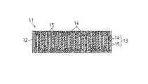
図1に示すように、成形体11は、高分子マトリックス12と、熱伝導性充填材13とを備えている。図1に示す成形体11はシート状に形成され、熱伝導性充填材13は、繊維状充填材14と、粒子状充填材15とを有している。この成形体11の形状については特に限定されず、立方体状、球状、円柱状、板状、フィルム状、チューブ状等の形状が挙げられる。繊維状充填材14は成形体11中で一定方向に配向されている。例えば、図1に示す成形体11においては、繊維状充填材14は成形体11の厚さ方向に沿って配向されている。 As shown in FIG. 1, the molded
成形体11は、組成物を調製する調製工程と、繊維状充填材14を一定方向に配向させる配向工程と、成形体11を成形する成形工程とを経て製造される。
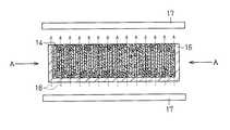
調製工程では、前記各成分が適宜に混合されて組成物が調製される。配向工程では、図2に示すように、例えば組成物が型16内に充填された後、繊維状充填材14が一定方向に配向される。繊維状充填材14の配向は、磁場発生装置を用いた組成物への磁場の印加、及び振動装置(図示略)を用いた組成物への振動の印加によって行われる。このとき、磁場及び振動は、組成物を介して繊維状充填材14に印加される。磁場発生装置及び振動装置は通常、型16の外方に配置されている。そのため、型16の材質は、組成物に磁場及び振動が容易に印加されることから、磁性体と異なるものが好ましく、例えば合成樹脂、及びアルミニウムが好ましい。The molded
In the preparation step, the components are appropriately mixed to prepare a composition. In the orientation step, as shown in FIG. 2, for example, after the composition is filled in the
磁場発生装置としては、永久磁石、電磁石、及び超伝導磁石が挙げられるが、長い繊維長を有する繊維状充填材14が容易に配向されることから、超伝導磁石が好ましい。組成物に印加される磁場の強度の下限、即ち磁場の磁束密度の下限は、500ガウスが好ましい。磁場の磁束密度が500ガウス未満の場合、繊維状充填材14が十分に配向されないおそれがある。磁場の磁束密度の上昇に伴って繊維状充填材14の配向の程度が高くなることから、磁場の磁束密度は高いほど好ましい。しかしながら、磁場の磁束密度の上昇に伴って磁場発生装置の構成が煩雑になることから、成形体11の製造コストが上昇する。従って、磁場の磁束密度の上限は、成形体11の製造コストが適切な範囲内に抑えられることから、100,000ガウスが好ましい。 Examples of the magnetic field generator include permanent magnets, electromagnets, and superconducting magnets. Superconducting magnets are preferred because the
組成物に印加される磁場の方向は、組成物中の繊維状充填材14に応じて適宜設定される。例えば、図2においては、磁場発生装置の一対の磁極17が型16の下方及び上方に配設されている。このとき、一対の磁極17の間には、成形体11の厚さ方向の沿うように直線状の磁力線18が発生する。繊維状充填材14が反磁性体である場合、組成物に磁場が印加されることにより、繊維状充填材14は、磁場の方向と反対方向に磁化されて磁力線18に沿って配向される。また、繊維状充填材14の結晶構造の結晶方位に依存して繊維状充填材14の磁化率が異方性を持つ場合、繊維状充填材14は、磁化率の異方性に従って配向される。 The direction of the magnetic field applied to the composition is appropriately set according to the
振動装置としては、電磁式振動装置、モータ振動装置、及びエアシリンダを用いた打鍵振動装置が挙げられる。組成物には振動とともに磁場が印加されることから、振動装置は、磁場雰囲気下においても正常に使用され得るものが好ましい。特に、磁場発生装置として超伝導磁石が用いられる場合、振動装置は高磁場雰囲気下で使用されることから、振動装置の電気系統は故障し易い。そのため、振動装置の材質は強磁性体と異なるものが好ましく、振動装置の動力源は圧縮空気が好ましい。具体的には、振動装置はエアシリンダを用いた打鍵振動装置が好ましい。 Examples of the vibration device include an electromagnetic vibration device, a motor vibration device, and a keystroke vibration device using an air cylinder. Since a magnetic field is applied to the composition together with vibration, it is preferable that the vibration device can be used normally even in a magnetic field atmosphere. In particular, when a superconducting magnet is used as the magnetic field generation device, the vibration device is used in a high magnetic field atmosphere, so the electric system of the vibration device is likely to fail. Therefore, the material of the vibration device is preferably different from the ferromagnetic material, and the power source of the vibration device is preferably compressed air. Specifically, the vibration device is preferably a keystroke vibration device using an air cylinder.
組成物に印加される振動の周波数は0.1〜4500Hzであり、0.1〜1000Hzが好ましく、1〜100Hzがより好ましい。振動の周波数が0.1Hz未満の場合、振動によって繊維状充填材14に加わるエネルギーが小さいことから、繊維状充填材14は十分に配向されず、成形体11の熱伝導性能が低下する。振動の周波数が4500Hzを超えると、組成物の全体にわたって振動が伝わらないことから、繊維状充填材14の配向が不均一となり、成形体11の熱伝導性能が低下する。振動の周波数を前記範囲に設定することにより、組成物の粘度が高い場合、例えば組成物の粘度が200,000mPa・s以上の場合にも、組成物に振動を印加することによって組成物の流動性を高めることができ、その結果、組成物の見かけ上の粘度が低下する。そのため、繊維状充填材14は、組成物中で移動し易くなって容易に配向され、成形体11は優れた熱伝導性能を発揮する。 The frequency of vibration applied to the composition is 0.1 to 4500 Hz, preferably 0.1 to 1000 Hz, and more preferably 1 to 100 Hz. When the frequency of vibration is less than 0.1 Hz, since the energy applied to the
組成物に印加される振動の加速度は1G以上であり、6〜50Gが好ましく、30〜50Gがより好ましい。振動の加速度が1G未満の場合、振動によって繊維状充填材14に加わるエネルギーが小さいことから繊維状充填材14は十分に配向されず、成形体11の熱伝導性能が低下する。更に、例えば振動の周波数が1.0Hz以下の場合、加速度が1G未満である振動を組成物に印加することは困難である。振動の加速度が50Gを超えると、振動の周波数が低い場合、例えば振動の周波数が50Hzである場合、振動によって組成物に加わるエネルギーが過剰に大きいことから、組成物が振動の印加によって型16内で揺動して組成物中の各成分の分布が不均一になるおそれがある。 The acceleration of vibration applied to the composition is 1 G or more, preferably 6 to 50 G, and more preferably 30 to 50 G. When the acceleration of vibration is less than 1 G, the energy applied to the
組成物に印加される振動の振幅は、前記周波数及び加速度に起因しており、0.1〜20mmが好ましく、1〜20mmがより好ましい。振動の振幅が0.1mm未満の場合、振動によって繊維状充填材14に加わるエネルギーが小さいことから、繊維状充填材14は十分に配向されないおそれがある。振動の振幅が20mmを超えると、組成物の全体にわたって振動が伝わらないことから、繊維状充填材14の配向が不均一となるおそれがある。振動の振幅を前記範囲に設定することにより、前記周波数と同様に、組成物の粘度が高い場合にも、組成物に振動を印加することによって組成物の流動性を高めることができ、その結果、繊維状充填材14は容易に配向される。 The amplitude of vibration applied to the composition is attributable to the frequency and acceleration, and is preferably 0.1 to 20 mm, more preferably 1 to 20 mm. When the amplitude of vibration is less than 0.1 mm, the energy applied to the
組成物に印加される振動の周波数、加速度、及び振幅は、繊維状充填材の平均繊維長、及び組成物の粘度によって適宜に調整され得る。例えば繊維状充填材の平均繊維長が短い場合、組成物に印加される振動の振幅は小さく設定されてもよい。また、繊維状充填材の平均繊維長が長い場合、例えば繊維状充填材の平均繊維長が6000μm以上である場合、組成物に印加される振動の周波数は、前記範囲内において低く設定され、且つ振動の振幅は大きく設定されてもよい。この場合、組成物に印加される振動の衝撃は大きくなる。尚、組成物に印加される振動の方向は特に限定されず、振動は、図2の矢印Aで示すように型16の左右方向から組成物に印加されてもよいし、例えば型16の上下方向から組成物に印加されてもよい。 The frequency, acceleration, and amplitude of vibration applied to the composition can be appropriately adjusted depending on the average fiber length of the fibrous filler and the viscosity of the composition. For example, when the average fiber length of the fibrous filler is short, the amplitude of vibration applied to the composition may be set small. Further, when the average fiber length of the fibrous filler is long, for example, when the average fiber length of the fibrous filler is 6000 μm or more, the frequency of vibration applied to the composition is set low within the above range, and The amplitude of vibration may be set large. In this case, the impact of vibration applied to the composition is increased. The direction of vibration applied to the composition is not particularly limited, and the vibration may be applied to the composition from the left and right direction of the
成形工程では、型16内において、繊維状充填材14の配向を維持した状態で高分子マトリックス12を硬化又は固化させることにより、図1に示すように、所定の形状を有する成形体11が成形される。 In the molding process, the
成形体11が発熱体及び放熱体に取付けられる際には、発熱体(例えば電子部品)上に成形体11及び放熱体が順に載置される。次いで、成形体11が発熱体及び放熱体に密着するように、例えば放熱体から発熱体に向かって荷重が加えられ、発熱体及び放熱体によって成形体11が挟持される。 When the molded
前記の実施形態によって発揮される効果について、以下に記載する。
・ 本実施形態の繊維状充填材14は、磁場及び振動の印加によって一定方向に配向される。そのため、例えば作業者の手作業によって繊維状充填材14が配列される場合に比べて、繊維状充填材14は容易に配向される。更に、組成物に印加される振動の周波数が0.1〜4500Hzに設定され、且つ振動の加速度が1G以上に設定されていることから、組成物の粘度が高い場合、例えば組成物の粘度が700,000mPa/s以上、又は1,200,000mPa・s以上の場合にも、振動の印加によって組成物の見かけ上の粘度は低下する。そのため、組成物の粘度が高い場合、例えば組成物中の熱伝導性充填材13の含有量が高い場合にも、繊維状充填材14は、組成物中を移動して容易に配向される。更に、組成物の見かけ上の粘度が低下することから、組成物の実際の粘度が高い場合にも、組成物中の気泡が振動の印加によって組成物から抜けやすくなり、組成物中の気泡に起因する高分子マトリックスの固化阻害、又は硬化阻害の発生を防止することができる。The effects exhibited by the above embodiment will be described below.
-The
また、繊維状充填材14の平均繊維長が長い場合、例えば繊維状充填材14の平均繊維長が6000μm以上である場合、組成物の粘度は高くなるとともに、繊維状充填材14は組成物中で絡み易くなる。しかしながら、周波数及び加速度が前記範囲に設定された振動が繊維状充填材14に印加されることにより、繊維状充填材14は組成物中で移動し易くなり、その結果、絡まった繊維状充填材14は容易に解れて配向される。従って、本実施形態の成形体11の製造方法では、繊維状充填材14の配向の容易さと、成形体11の熱伝導性能の向上とを同時に達成することができ、優れた熱伝導性能を発揮する成形体11を製造することができる。具体的には、本実施形態の製造方法によって製造される成形体11において、繊維状充填材14の配向方向における熱伝導率は、20W/m・k以上を達成することができ、例えば50W/m・k以上を達成することができる。更に、成形体11の熱抵抗率は、0.4℃/W以下を達成することができる。 Moreover, when the average fiber length of the
一方、超音波振動の周波数は通常、20,000Hz以上である。そのため、高粘度の組成物に超音波振動が印加された場合、超音波振動の周波数が過剰に高いことから、組成物に加わる振動は微振動となり、組成物の全体にわたって振動が伝わることが困難となる。更に、組成物に加わる振動の周波数は組成物の固有振動数から大きく離れることから、組成物の見かけ上の粘度は低下しない。そのため、組成物の粘度が高い状態で繊維状充填材14が配向されることから、繊維状充填材14の配向が不十分となるおそれがある。 On the other hand, the frequency of ultrasonic vibration is usually 20,000 Hz or more. Therefore, when ultrasonic vibration is applied to a high-viscosity composition, the frequency of the ultrasonic vibration is excessively high, so the vibration applied to the composition is minute and difficult to transmit throughout the composition. It becomes. Furthermore, since the frequency of vibration applied to the composition deviates greatly from the natural frequency of the composition, the apparent viscosity of the composition does not decrease. Therefore, since the
・ 繊維状充填材14には、磁場とともに振動が印加されることから、磁場のみが印加される場合に比べて、低い磁束密度を有する磁場、例えば磁場のみが印加される際の磁束密度の3分の1程度の磁束密度を有する磁場によって容易に配向される。そのため、磁場のみの印加によって繊維状充填材14が配向される場合に比べて、成形体11の製造コストを低減することができる。 Since vibration is applied to the
・ 繊維状充填材14は組成物中で配向され、その繊維状充填材14の配向を維持した状態で成形体11が成形されることから、成形体11の形状は特に限定されず、自由に設定され得る。 -Since the
なお、本実施形態は、次のように変更して具体化することも可能である。
・ 前記熱伝導性充填材13は、高分子マトリックス12と熱伝導性充填材13との密着性を高めるために、例えばシランカップリング剤、又はチタネートカップリング剤を用いた表面処理が施されてもよいし、熱伝導性充填材13に絶縁性を付与するために、絶縁材料を用いた表面処理が施されてもよい。In addition, this embodiment can also be changed and embodied as follows.
The heat
・ 前記配向工程及び成形工程において、基材フィルム上に組成物を塗布した後、基材フィルム上で繊維状充填材14を配向させて成形体11を成形してもよい。
・ 前記成形工程後の成形体11は、所望の形状に切断されてもよい。-In the said orientation process and a formation process, after apply | coating a composition on a base film, you may shape | mold the molded
-The molded
・ 前記調製工程、又は配向工程において、組成物の脱泡を行ってもよい。 -In the said preparation process or an orientation process, you may defoam a composition.
次に、実施例及び比較例を挙げて前記実施形態をさらに具体的に説明する。
(実施例1〜7、及び比較例1〜3)
実施例1においては、調製工程として、高分子マトリックス12としての付加型の液状シリコーンゲルに、繊維状充填材14としての炭素繊維と、粒子状充填材15としての球状アルミナとを混合して、成形体11用の組成物を調製した。各成分の配合量を表1に示す。表1において、各成分の配合量の数値は重量部を示す。液状シリコーンゲルの25℃における粘度は400mPa・sであり、液状シリコーンゲルの比重は1.0であった。炭素繊維の平均繊維径は10μmであり、炭素繊維の平均繊維長は3000μmであった。球状アルミナの平均粒径は3.2μmであった。次に、炭素繊維及び球状アルミナが均一に分散されるまで組成物を攪拌した後、組成物の脱泡を行った。Next, the embodiment will be described more specifically with reference to examples and comparative examples.
(Examples 1-7 and Comparative Examples 1-3)
In Example 1, as a preparation process, carbon fiber as the
続いて、配向工程として、回転粘度計を用いて組成物の25℃における粘度を測定した後、型16内に組成物を充填した。粘度の測定結果を表1に示す。次に、超伝導磁石を用いて、100,000ガウスの磁束密度を有する磁場を組成物に印加するとともに、圧縮空気を用いて、0.1Hzの周波数、4.5Gの加速度、及び20mmの振幅を有する振動を型16を介して組成物に印加して、炭素繊維を成形体11の厚さ方向に沿って配向させた。次いで、成形工程として、組成物を120℃で30分加熱することにより、液状シリコーンゲルを硬化させてシート状の成形体11を得た。 Subsequently, as an alignment step, the viscosity of the composition at 25 ° C. was measured using a rotational viscometer, and then the composition was filled into the
次に、実施例2では、球状アルミナの配合量を表1に示すように変更した。更に実施例2では、振動の周波数を3.0Hz、及び振動の振幅を10mmに変更した以外は、実施例1と同様にして成形体11を得た。実施例3では、炭素繊維の平均繊維長を130μmに変更した以外は、実施例2と同様にして成形体11を得た。実施例4では、炭素繊維の平均繊維長を6000μmに変更し、球状アルミナの配合量を表1に示すように変更した以外は、実施例2と同様にして成形体11を得た。 Next, in Example 2, the amount of spherical alumina was changed as shown in Table 1. Further, in Example 2, a molded
実施例5では、炭素繊維の平均繊維長を100μmに変更し、炭素繊維及び球状アルミナの配合量を表1に示すように変更した。更に実施例5では、振動の周波数を100Hz、振動の加速度を50G、及び振動の振幅を0.1mmに変更した以外は、実施例2と同様にして成形体11を得た。 In Example 5, the average fiber length of carbon fibers was changed to 100 μm, and the blending amounts of carbon fibers and spherical alumina were changed as shown in Table 1. Further, in Example 5, a molded
実施例6では、繊維状充填材14としてポリパラフェニレンベンゾビスオキサゾール前駆体炭素繊維(PBO炭素繊維)を用いた以外は、実施例2と同様にして組成物を調製した。PBO炭素繊維の平均繊維長は6000μmであった。更に実施例6では、振動の周波数を3.0Hzに変更した以外は、実施例1と同様にして成形体11を得た。 In Example 6, a composition was prepared in the same manner as in Example 2 except that polyparaphenylene benzobisoxazole precursor carbon fiber (PBO carbon fiber) was used as the
実施例7では、繊維状充填材14としてPBO炭素繊維を用いた以外は、実施例2と同様にして組成物を調製した。PBO炭素繊維の平均繊維長は150μmであった。更に実施例7では、振動の周波数を3.0Hz、及び振動の加速度を3.0Gに変更した以外は、実施例1と同様にして成形体11を得た。 In Example 7, a composition was prepared in the same manner as in Example 2 except that PBO carbon fiber was used as the
比較例1では、配向工程での振動の印加を省略した以外は、実施例1と同様にして成形体11を得た。比較例2では、炭素繊維の平均繊維長を50μmに変更し、配向工程での振動の印加を省略した以外は、実施例2と同様にして成形体11を得た。比較例3では、超音波を用いて組成物に振動を印加した以外は、実施例1と同様にして成形体11を得た。比較例1〜3において、各成分の配合量を表2に示す。表2において、各成分の配合量の数値は重量部を示す。超音波の周波数は20,000Hzであり、加速度は4800Gであり、振幅は3〜4μmであった。そして、各例の成形体11について、下記の各項目に関して測定を行った。その結果を表1及び表2に示す。 In Comparative Example 1, a molded
<熱伝導率>
各例の成形体11から円板状の試験片(直径:10mm、厚さ:0.5mm)を得た後、レーザーフラッシュ法により試験片の熱伝導率を測定した。<Thermal conductivity>
After obtaining a disk-shaped test piece (diameter: 10 mm, thickness: 0.5 mm) from the molded
<熱抵抗値>
各例の成形体11について、それらを発熱体及び放熱体で挟持した後、厚さ方向に50%圧縮したときの厚さ方向における熱抵抗値を測定した。<Thermal resistance value>
About the molded

(実施例8及び比較例4)
実施例8及び比較例4では、振動の周波数を表3に示すように設定するとともに、振動の加速度を4.5Gに設定した以外は、実施例1と同様にして成形体11を得た。そして、実施例8の成形体11及び比較例4の成形体11中の繊維状充填材14の配向状態を観察した。その結果を表3に示す。表3中の“配向”欄における数値は繊維状充填材14の配向の程度を表し、数値が大きいほど配向の程度が高いことを示す。更に、“0”は繊維状充填材14が配向していなかったことを示す。
(Example 8 and Comparative Example 4)
In Example 8 and Comparative Example 4, a molded
(実施例9)
実施例9では、振動の周波数を50Hzに設定するとともに、振動の加速度を表4に示すように設定した以外は、実施例1と同様にして成形体11を得た。そして、実施例9の各成形体11中の繊維状充填材14の配向状態を観察した。その結果を表4に示す。表4中の“配向”欄における数値の意味は、表3と同じである。
Example 9
In Example 9, a molded
(実施例10)
実施例10では、振動の周波数を表5に示すように設定するとともに、振動の加速度を1Gに設定した以外は、実施例1と同様にして成形体11を得た。そして、実施例10の成形体11中の繊維状充填材14の配向状態を観察した。その結果を表5に示す。表5中の“配向”欄における数値の意味は、表3と同じである。
(Example 10)
In Example 10, a molded
11…成形体、12…高分子マトリックス、13…熱伝導性充填材、14…繊維状の熱伝導性充填材としての繊維状充填材。 DESCRIPTION OF
Claims (6)
Translated fromJapanese前記熱伝導性充填材の少なくとも一部が繊維状に形成され、
前記熱伝導性高分子組成物を調製する調製工程と、
前記繊維状の熱伝導性充填材に磁場及び振動を印加して、繊維状の熱伝導性充填材を一定方向に配向させる配向工程と、
前記熱伝導性充填材の配向を維持した状態で熱伝導性成形体を成形する成形工程とを備え、
前記振動の周波数が0.1〜4500Hzに設定されているとともに、振動の加速度が1G以上に設定されていることを特徴とする熱伝導性成形体の製造方法。A method for producing a thermally conductive molded article molded from a thermally conductive polymer composition containing a polymer matrix and a thermally conductive filler,
At least a portion of the thermally conductive filler is formed into a fiber,
A preparation step of preparing the thermally conductive polymer composition;
An alignment step of applying a magnetic field and vibration to the fibrous heat conductive filler to orient the fibrous heat conductive filler in a certain direction;
A molding step of molding a thermally conductive molded body while maintaining the orientation of the thermally conductive filler,
The method for producing a thermally conductive molded article, wherein the vibration frequency is set to 0.1 to 4500 Hz and the vibration acceleration is set to 1 G or more.
Priority Applications (1)
| Application Number | Priority Date | Filing Date | Title |
|---|---|---|---|
| JP2005164500AJP4657816B2 (en) | 2005-06-03 | 2005-06-03 | Method for producing thermally conductive molded body and thermally conductive molded body |
Applications Claiming Priority (1)
| Application Number | Priority Date | Filing Date | Title |
|---|---|---|---|
| JP2005164500AJP4657816B2 (en) | 2005-06-03 | 2005-06-03 | Method for producing thermally conductive molded body and thermally conductive molded body |
Publications (2)
| Publication Number | Publication Date |
|---|---|
| JP2006335957Atrue JP2006335957A (en) | 2006-12-14 |
| JP4657816B2 JP4657816B2 (en) | 2011-03-23 |
Family
ID=37556786
Family Applications (1)
| Application Number | Title | Priority Date | Filing Date |
|---|---|---|---|
| JP2005164500AExpired - LifetimeJP4657816B2 (en) | 2005-06-03 | 2005-06-03 | Method for producing thermally conductive molded body and thermally conductive molded body |
Country Status (1)
| Country | Link |
|---|---|
| JP (1) | JP4657816B2 (en) |
Cited By (17)
| Publication number | Priority date | Publication date | Assignee | Title |
|---|---|---|---|---|
| JP2008214543A (en)* | 2007-03-06 | 2008-09-18 | Teijin Ltd | Carbon fiber composite and its production method |
| JP2009013390A (en)* | 2007-06-04 | 2009-01-22 | Teijin Ltd | Thermally conductive sheet |
| JP2011000824A (en)* | 2009-06-19 | 2011-01-06 | Nitto Denko Corp | Heat-conductive polyimide molding, and manufacturing method therefor |
| US8287975B2 (en) | 2007-03-29 | 2012-10-16 | Polymatech Co., Ltd. | Laminated body |
| WO2013175744A1 (en) | 2012-05-21 | 2013-11-28 | 東洋インキScホールディングス株式会社 | Easily deformable aggregates and process for producing same, thermally conductive resin composition, thermally conductive member and process for producing same, and thermally conductive adhesion sheet |
| KR20160013270A (en) | 2013-06-27 | 2016-02-03 | 데쿠세리아루즈 가부시키가이샤 | Thermally conductive sheet, method for producing same, and semiconductor device |
| KR20160021830A (en) | 2013-06-19 | 2016-02-26 | 데쿠세리아루즈 가부시키가이샤 | Thermally conductive sheet and process for manufacturing thermally conductive sheet |
| WO2018225468A1 (en)* | 2017-06-09 | 2018-12-13 | 三菱瓦斯化学株式会社 | Method for manufacturing anisotropic filler-containing sheet |
| CN110982273A (en)* | 2018-10-03 | 2020-04-10 | 信越化学工业株式会社 | Resin sheet with controlled thermal conductivity distribution and method for manufacturing same |
| CN111500070A (en)* | 2020-04-14 | 2020-08-07 | 南方科技大学 | Carbon fiber oriented thermal interface material and preparation method thereof |
| CN112976438A (en)* | 2021-01-28 | 2021-06-18 | 华中科技大学 | Preparation method and product of directionally interconnected high-thermal-conductivity interface material |
| JP2022512188A (en)* | 2018-12-10 | 2022-02-02 | ボストン・マテリアルズ・インコーポレイテッド | Systems and methods for carbon fiber alignment and fiber reinforced composites |
| CN114907654A (en)* | 2022-05-16 | 2022-08-16 | 南京工业大学 | Anisotropic high thermal conductivity plasticized polyvinyl chloride functional film and preparation method thereof |
| US11541580B2 (en) | 2018-04-27 | 2023-01-03 | Niigata University | Method for preparing compact of resin compound having anisotropy |
| CN115625946A (en)* | 2022-10-14 | 2023-01-20 | 深圳市鸿富诚新材料股份有限公司 | A kind of thermal interface material and its preparation method and application |
| TWI794554B (en)* | 2019-11-04 | 2023-03-01 | 聯茂電子股份有限公司 | Method for manufacturing a multilayer structure and a substrate |
| US12428587B1 (en) | 2024-09-03 | 2025-09-30 | Boston Materials, Inc. | Liquid metal compositions and methods |
Citations (5)
| Publication number | Priority date | Publication date | Assignee | Title |
|---|---|---|---|---|
| JPS61194703A (en)* | 1985-02-22 | 1986-08-29 | Japan Steel Works Ltd:The | Magnetic field injection molding control method |
| JPH0577269A (en)* | 1991-05-20 | 1993-03-30 | Japan Steel Works Ltd:The | Injection molding method for anisotropic resin magnet and its injection molding device |
| JP2000141505A (en)* | 1998-11-09 | 2000-05-23 | Polymatech Co Ltd | Method for molding polymer composite material and magnetic field-orientated press molding device |
| JP2001106799A (en)* | 1999-10-08 | 2001-04-17 | Polymatech Co Ltd | Polymeric composite material molded product and method for producing the same |
| JP2002003717A (en)* | 2000-06-21 | 2002-01-09 | Polymatech Co Ltd | Thermal conductive sheet |
- 2005
- 2005-06-03JPJP2005164500Apatent/JP4657816B2/ennot_activeExpired - Lifetime
Patent Citations (5)
| Publication number | Priority date | Publication date | Assignee | Title |
|---|---|---|---|---|
| JPS61194703A (en)* | 1985-02-22 | 1986-08-29 | Japan Steel Works Ltd:The | Magnetic field injection molding control method |
| JPH0577269A (en)* | 1991-05-20 | 1993-03-30 | Japan Steel Works Ltd:The | Injection molding method for anisotropic resin magnet and its injection molding device |
| JP2000141505A (en)* | 1998-11-09 | 2000-05-23 | Polymatech Co Ltd | Method for molding polymer composite material and magnetic field-orientated press molding device |
| JP2001106799A (en)* | 1999-10-08 | 2001-04-17 | Polymatech Co Ltd | Polymeric composite material molded product and method for producing the same |
| JP2002003717A (en)* | 2000-06-21 | 2002-01-09 | Polymatech Co Ltd | Thermal conductive sheet |
Cited By (28)
| Publication number | Priority date | Publication date | Assignee | Title |
|---|---|---|---|---|
| JP2008214543A (en)* | 2007-03-06 | 2008-09-18 | Teijin Ltd | Carbon fiber composite and its production method |
| US8287975B2 (en) | 2007-03-29 | 2012-10-16 | Polymatech Co., Ltd. | Laminated body |
| JP2009013390A (en)* | 2007-06-04 | 2009-01-22 | Teijin Ltd | Thermally conductive sheet |
| JP2011000824A (en)* | 2009-06-19 | 2011-01-06 | Nitto Denko Corp | Heat-conductive polyimide molding, and manufacturing method therefor |
| US10370573B2 (en) | 2012-05-21 | 2019-08-06 | Toyo Ink Sc Holdings Co., Ltd. | Easily deformable aggregate and method for manufacturing same, thermally conductive resin composition, thermally conductive member and method for manufacturing same, and thermally conductive adhesive sheet |
| WO2013175744A1 (en) | 2012-05-21 | 2013-11-28 | 東洋インキScホールディングス株式会社 | Easily deformable aggregates and process for producing same, thermally conductive resin composition, thermally conductive member and process for producing same, and thermally conductive adhesion sheet |
| KR20150013721A (en) | 2012-05-21 | 2015-02-05 | 토요잉크Sc홀딩스주식회사 | Easily deformable aggregates and process for producing same, thermally conductive resin composition, thermally conductive member and process for producing same, and thermally conductive adhesion sheet |
| KR20160021830A (en) | 2013-06-19 | 2016-02-26 | 데쿠세리아루즈 가부시키가이샤 | Thermally conductive sheet and process for manufacturing thermally conductive sheet |
| US10012453B2 (en) | 2013-06-19 | 2018-07-03 | Dexerials Corporation | Thermally conductive sheet and method for producing thermally conductive sheet |
| KR20180099946A (en) | 2013-06-19 | 2018-09-05 | 데쿠세리아루즈 가부시키가이샤 | Thermally conductive sheet and process for manufacturing thermally conductive sheet |
| KR20160013270A (en) | 2013-06-27 | 2016-02-03 | 데쿠세리아루즈 가부시키가이샤 | Thermally conductive sheet, method for producing same, and semiconductor device |
| US9966324B2 (en) | 2013-06-27 | 2018-05-08 | Dexerials Corporation | Thermally conductive sheet, method for producing same, and semiconductor device |
| JP7120229B2 (en) | 2017-06-09 | 2022-08-17 | 三菱瓦斯化学株式会社 | Method for manufacturing anisotropic filler-containing sheet |
| WO2018225468A1 (en)* | 2017-06-09 | 2018-12-13 | 三菱瓦斯化学株式会社 | Method for manufacturing anisotropic filler-containing sheet |
| JPWO2018225468A1 (en)* | 2017-06-09 | 2020-04-09 | 三菱瓦斯化学株式会社 | Method for producing sheet containing anisotropic filler |
| US11541580B2 (en) | 2018-04-27 | 2023-01-03 | Niigata University | Method for preparing compact of resin compound having anisotropy |
| CN110982273A (en)* | 2018-10-03 | 2020-04-10 | 信越化学工业株式会社 | Resin sheet with controlled thermal conductivity distribution and method for manufacturing same |
| KR20200038421A (en) | 2018-10-03 | 2020-04-13 | 신에쓰 가가꾸 고교 가부시끼가이샤 | Resin Sheet Having Controlled Thermal Conductivity Distribution, and Method for Manufacturing the Same |
| JP2022512188A (en)* | 2018-12-10 | 2022-02-02 | ボストン・マテリアルズ・インコーポレイテッド | Systems and methods for carbon fiber alignment and fiber reinforced composites |
| TWI794554B (en)* | 2019-11-04 | 2023-03-01 | 聯茂電子股份有限公司 | Method for manufacturing a multilayer structure and a substrate |
| CN111500070A (en)* | 2020-04-14 | 2020-08-07 | 南方科技大学 | Carbon fiber oriented thermal interface material and preparation method thereof |
| CN112976438B (en)* | 2021-01-28 | 2022-07-12 | 华中科技大学 | A kind of preparation method and product of directional interconnected high thermal conductivity interface material |
| CN112976438A (en)* | 2021-01-28 | 2021-06-18 | 华中科技大学 | Preparation method and product of directionally interconnected high-thermal-conductivity interface material |
| CN114907654A (en)* | 2022-05-16 | 2022-08-16 | 南京工业大学 | Anisotropic high thermal conductivity plasticized polyvinyl chloride functional film and preparation method thereof |
| CN114907654B (en)* | 2022-05-16 | 2023-04-18 | 南京工业大学 | Anisotropic high-thermal-conductivity plasticized polyvinyl chloride functional film and preparation method thereof |
| CN115625946A (en)* | 2022-10-14 | 2023-01-20 | 深圳市鸿富诚新材料股份有限公司 | A kind of thermal interface material and its preparation method and application |
| CN115625946B (en)* | 2022-10-14 | 2025-08-19 | 深圳市鸿富诚新材料股份有限公司 | Heat conduction interface material and preparation method and application thereof |
| US12428587B1 (en) | 2024-09-03 | 2025-09-30 | Boston Materials, Inc. | Liquid metal compositions and methods |
Also Published As
| Publication number | Publication date |
|---|---|
| JP4657816B2 (en) | 2011-03-23 |
Similar Documents
| Publication | Publication Date | Title |
|---|---|---|
| JP4657816B2 (en) | Method for producing thermally conductive molded body and thermally conductive molded body | |
| JP4897360B2 (en) | Thermally conductive molded body and method for producing the same | |
| JP6671735B2 (en) | Manufacturing method of heat conductive sheet | |
| JP5541400B2 (en) | Manufacturing method of heat conductive sheet | |
| JP4714371B2 (en) | Thermally conductive molded body and method for producing the same | |
| JP2002121404A (en) | Heat-conductive polymer sheet | |
| JP5541399B2 (en) | Thermally conductive sheet | |
| JP2000281802A (en) | Thermoconductive formed shape, its production, and semiconductor device | |
| JP2005146057A (en) | High-thermal-conductivity molding and method for producing the same | |
| JP5254870B2 (en) | Thermally conductive sheet and method for producing the same | |
| JP2002088171A (en) | Heat-conductive sheet and method for producing the same and heat radiation device | |
| JP6650176B1 (en) | Thermal conductive sheet | |
| JP4814550B2 (en) | Method for producing thermally conductive molded body | |
| CN111699090A (en) | Thermally conductive sheet | |
| JP2002146672A (en) | Heat conductive filler, heat conductive adhesive and semiconductor device | |
| JP5015366B2 (en) | Thermally conductive molded body and method for producing the same | |
| JP4791146B2 (en) | Thermally conductive member and manufacturing method thereof | |
| JP6657784B2 (en) | Composite resin composition, molded body, heat conductive material and heat conductive material | |
| JP5416174B2 (en) | Thermally conductive molded body | |
| TW202028316A (en) | Resin sheet having controlled thermal conductivity distribution, and method for manufacturing the same | |
| CN114716704A (en) | A kind of high thermal conductivity graphene composite film and preparation method thereof | |
| JP2005139267A (en) | Heat-conductive molded article | |
| WO2023190587A1 (en) | Thermally conductive sheet and method for producing thermally conductive sheet |
Legal Events
| Date | Code | Title | Description |
|---|---|---|---|
| A621 | Written request for application examination | Free format text:JAPANESE INTERMEDIATE CODE: A621 Effective date:20080526 | |
| A977 | Report on retrieval | Free format text:JAPANESE INTERMEDIATE CODE: A971007 Effective date:20101125 | |
| TRDD | Decision of grant or rejection written | ||
| A01 | Written decision to grant a patent or to grant a registration (utility model) | Free format text:JAPANESE INTERMEDIATE CODE: A01 Effective date:20101130 | |
| A01 | Written decision to grant a patent or to grant a registration (utility model) | Free format text:JAPANESE INTERMEDIATE CODE: A01 | |
| A61 | First payment of annual fees (during grant procedure) | Free format text:JAPANESE INTERMEDIATE CODE: A61 Effective date:20101222 | |
| FPAY | Renewal fee payment (event date is renewal date of database) | Free format text:PAYMENT UNTIL: 20140107 Year of fee payment:3 | |
| R150 | Certificate of patent or registration of utility model | Free format text:JAPANESE INTERMEDIATE CODE: R150 Ref document number:4657816 Country of ref document:JP Free format text:JAPANESE INTERMEDIATE CODE: R150 | |
| R250 | Receipt of annual fees | Free format text:JAPANESE INTERMEDIATE CODE: R250 | |
| S111 | Request for change of ownership or part of ownership | Free format text:JAPANESE INTERMEDIATE CODE: R313111 | |
| R350 | Written notification of registration of transfer | Free format text:JAPANESE INTERMEDIATE CODE: R350 | |
| R250 | Receipt of annual fees | Free format text:JAPANESE INTERMEDIATE CODE: R250 | |
| R250 | Receipt of annual fees | Free format text:JAPANESE INTERMEDIATE CODE: R250 | |
| R250 | Receipt of annual fees | Free format text:JAPANESE INTERMEDIATE CODE: R250 | |
| R250 | Receipt of annual fees | Free format text:JAPANESE INTERMEDIATE CODE: R250 | |
| S533 | Written request for registration of change of name | Free format text:JAPANESE INTERMEDIATE CODE: R313533 | |
| R350 | Written notification of registration of transfer | Free format text:JAPANESE INTERMEDIATE CODE: R350 | |
| R250 | Receipt of annual fees | Free format text:JAPANESE INTERMEDIATE CODE: R250 | |
| R250 | Receipt of annual fees | Free format text:JAPANESE INTERMEDIATE CODE: R250 | |
| R250 | Receipt of annual fees | Free format text:JAPANESE INTERMEDIATE CODE: R250 | |
| R250 | Receipt of annual fees | Free format text:JAPANESE INTERMEDIATE CODE: R250 | |
| R250 | Receipt of annual fees | Free format text:JAPANESE INTERMEDIATE CODE: R250 | |
| R250 | Receipt of annual fees | Free format text:JAPANESE INTERMEDIATE CODE: R250 | |
| R250 | Receipt of annual fees | Free format text:JAPANESE INTERMEDIATE CODE: R250 | |
| EXPY | Cancellation because of completion of term |