JP2006334414A - System and method for sealing tissue - Google Patents
System and method for sealing tissueDownload PDFInfo
- Publication number
- JP2006334414A JP2006334414AJP2006155442AJP2006155442AJP2006334414AJP 2006334414 AJP2006334414 AJP 2006334414AJP 2006155442 AJP2006155442 AJP 2006155442AJP 2006155442 AJP2006155442 AJP 2006155442AJP 2006334414 AJP2006334414 AJP 2006334414A
- Authority
- JP
- Japan
- Prior art keywords
- tip
- tissue
- rivet
- shape
- head
- Prior art date
- Legal status (The legal status is an assumption and is not a legal conclusion. Google has not performed a legal analysis and makes no representation as to the accuracy of the status listed.)
- Pending
Links
Images


Classifications
- A—HUMAN NECESSITIES
- A61—MEDICAL OR VETERINARY SCIENCE; HYGIENE
- A61B—DIAGNOSIS; SURGERY; IDENTIFICATION
- A61B17/00—Surgical instruments, devices or methods
- A61B17/064—Surgical staples, i.e. penetrating the tissue
- A61B17/0643—Surgical staples, i.e. penetrating the tissue with separate closing member, e.g. for interlocking with staple
- A—HUMAN NECESSITIES
- A61—MEDICAL OR VETERINARY SCIENCE; HYGIENE
- A61B—DIAGNOSIS; SURGERY; IDENTIFICATION
- A61B17/00—Surgical instruments, devices or methods
- A61B17/064—Surgical staples, i.e. penetrating the tissue
- A61B17/0644—Surgical staples, i.e. penetrating the tissue penetrating the tissue, deformable to closed position
- A—HUMAN NECESSITIES
- A61—MEDICAL OR VETERINARY SCIENCE; HYGIENE
- A61B—DIAGNOSIS; SURGERY; IDENTIFICATION
- A61B17/00—Surgical instruments, devices or methods
- A61B17/04—Surgical instruments, devices or methods for suturing wounds; Holders or packages for needles or suture materials
- A61B17/0401—Suture anchors, buttons or pledgets, i.e. means for attaching sutures to bone, cartilage or soft tissue; Instruments for applying or removing suture anchors
- A61B2017/0408—Rivets
- A—HUMAN NECESSITIES
- A61—MEDICAL OR VETERINARY SCIENCE; HYGIENE
- A61B—DIAGNOSIS; SURGERY; IDENTIFICATION
- A61B17/00—Surgical instruments, devices or methods
- A61B17/04—Surgical instruments, devices or methods for suturing wounds; Holders or packages for needles or suture materials
- A61B17/0401—Suture anchors, buttons or pledgets, i.e. means for attaching sutures to bone, cartilage or soft tissue; Instruments for applying or removing suture anchors
- A61B2017/042—Suture anchors, buttons or pledgets, i.e. means for attaching sutures to bone, cartilage or soft tissue; Instruments for applying or removing suture anchors plastically deformed during insertion
- A—HUMAN NECESSITIES
- A61—MEDICAL OR VETERINARY SCIENCE; HYGIENE
- A61B—DIAGNOSIS; SURGERY; IDENTIFICATION
- A61B17/00—Surgical instruments, devices or methods
- A61B17/064—Surgical staples, i.e. penetrating the tissue
- A61B2017/0647—Surgical staples, i.e. penetrating the tissue having one single leg, e.g. tacks
Landscapes
- Health & Medical Sciences (AREA)
- Life Sciences & Earth Sciences (AREA)
- Surgery (AREA)
- Heart & Thoracic Surgery (AREA)
- Engineering & Computer Science (AREA)
- Biomedical Technology (AREA)
- Nuclear Medicine, Radiotherapy & Molecular Imaging (AREA)
- Medical Informatics (AREA)
- Molecular Biology (AREA)
- Animal Behavior & Ethology (AREA)
- General Health & Medical Sciences (AREA)
- Public Health (AREA)
- Veterinary Medicine (AREA)
- Surgical Instruments (AREA)
Abstract
Description
Translated fromJapanese (優先権主張)
本出願は、米国仮特許出願第60/687,074号(標題「Medical Fastener」、Ken Blierらにより、2005年6月3日に出願)に対する優先権を主張する。(Priority claim)
This application claims priority to US Provisional Patent Application No. 60 / 687,074 (titled “Medical Fastener”, filed June 3, 2005 by Ken Brier et al.).
(背景)
(1.技術分野)
本開示は、一般に、医療用ファスナーに関し、より具体的には、組織を貫通して、そこで止血を誘導するための医療用リベットに関する。(background)
(1. Technical field)
The present disclosure relates generally to medical fasteners, and more specifically to medical rivets for penetrating tissue and inducing hemostasis there.
(2.関連技術の背景)
外科手術処置の間、具体的には、組織をシールしている間に、種々の医療用ファスナー(例えば、ステープル)が使用される。ファスナーは、一般に、シールプロセスを自動化する外科用器具(例えば、ステープラー)を用いて適用される。従って、ファスナーを使用することは、特定の状況において好ましい。なぜなら、ファスナーを適用すると、他の組織シール方法(例えば、縫合)よりも時間がかからないからである。(2. Background of related technology)
Various medical fasteners (e.g., staples) are used during surgical procedures, specifically while sealing tissue. Fasteners are generally applied using a surgical instrument (eg, a stapler) that automates the sealing process. Therefore, the use of fasteners is preferred in certain situations. This is because applying a fastener takes less time than other tissue sealing methods (eg, suturing).
代表的には、ファスナーは、対応する厚みの組織に貫通し、この組織をシールするために特定の長さがなければならない。従って、種々の厚みの組織において止血をもたらすファスナーが必要である。 Typically, fasteners must penetrate a corresponding thickness of tissue and have a certain length to seal the tissue. Therefore, there is a need for a fastener that provides hemostasis in various thickness tissues.
(要旨)
本開示は、第1表面と第2表面とを有し、かつそこで止血をもたらす、組織を固定するための医療用リベットを提供する。そのリベットは、近位端に頭部と、遠位端に先端とを有するシャフトを備える。前記先端は、両方の表面を通してこの組織を貫通し、かつその組織の第2表面でキノコ形先端または変形B字形先端を形成して、この組織を先端と、第1表面と接触している頭部との間に固定する。このキノコ形の先端および/またはこの変形B字形の先端の直径は、この組織の厚みに依存して変化する。このリベットはまた、頭部と、組織の第1表面と接触するように構成されたプレートとの間に配置された1つ以上のばね様構造体を備える。キノコ形の先端および/またはB字形の先端の形成の際に、このばね様構造体は、その組織の厚みに拘わらず、その組織に対して実質的に一定の圧力を維持する。(Summary)
The present disclosure provides a medical rivet for securing tissue having a first surface and a second surface and providing hemostasis therein. The rivet comprises a shaft having a head at the proximal end and a tip at the distal end. The tip penetrates the tissue through both surfaces and forms a mushroom-shaped tip or a modified B-shaped tip at the second surface of the tissue so that the tissue is in contact with the tip and the first surface. Secure between the parts. The diameter of the mushroom-shaped tip and / or the modified B-shaped tip varies depending on the thickness of the tissue. The rivet also includes one or more spring-like structures disposed between the head and a plate configured to contact the first surface of the tissue. Upon formation of the mushroom-shaped tip and / or the B-shaped tip, the spring-like structure maintains a substantially constant pressure against the tissue regardless of the thickness of the tissue.
本開示の一局面に従って、第1表面と第2表面とを有する組織をシールするためのシステムが開示される。このシステムは、シャフトを有する1つ以上のリベットを備え、このシャフトは、近位端と遠位端とを有する。このリベットは、近位端に頭部と、遠位端に先端とをさらに備え、ここでこの先端は、組織貫通に適した形状を有し、かつ第1表面および第2表面を通して組織を貫通するために適合されている。このシステムはまた、アンビルを備え、このアンビルは、先端と相互に作用する(interface)ように適合され、かつ先端に圧力を付与すると、先端の形状を変化させて、第1表面と接触している頭部と、第2表面と接触している先端との間に組織を固定するように適合されたくぼみを有する。 In accordance with one aspect of the present disclosure, a system for sealing tissue having a first surface and a second surface is disclosed. The system includes one or more rivets having a shaft, the shaft having a proximal end and a distal end. The rivet further comprises a head at the proximal end and a tip at the distal end, wherein the tip has a shape suitable for tissue penetration and penetrates tissue through the first and second surfaces. Have been adapted to. The system also includes an anvil that is adapted to interface with the tip and changes the shape of the tip when in contact with the first surface when pressure is applied to the tip. A recess adapted to secure tissue between the head and the tip in contact with the second surface.
本開示の別の局面に従って、第1表面と第2表面とを有する組織をシールするための医療用リベットが開示される。このリベットは、近位端と遠位端とを有するシャフト、このシャフトの近位端に配置された頭部、このシャフトの遠位端に配置された先端を備える。この先端は、組織貫通に適した形状を有し、かつ第1表面および第2表面を通して組織を貫通するために適合されている。この先端の形状は、先端に圧力を付与すると変化して、第1表面と接触している頭部と、第2表面と接触している先端との間に組織を固定するために適合される。 In accordance with another aspect of the present disclosure, a medical rivet for sealing tissue having a first surface and a second surface is disclosed. The rivet includes a shaft having a proximal end and a distal end, a head disposed at the proximal end of the shaft, and a tip disposed at the distal end of the shaft. The tip has a shape suitable for tissue penetration and is adapted to penetrate tissue through the first surface and the second surface. The shape of the tip changes when pressure is applied to the tip and is adapted to fix tissue between the head in contact with the first surface and the tip in contact with the second surface. .
本開示のさらなる局面に従って、第1表面と第2表面とを有する組織をシールするための方法が開示される。この方法は、少なくとも1つのリベットで、第1表面および第2表面を通して組織を貫通する工程を包含する。このリベットは、近位端と遠位端とを有するシャフトを備える。このリベットは、近位端に頭部と、遠位端に先端とをさらに備える。この方法はまた、先端に圧力を付与して、先端の形状を変化させ、かつ第1表面と接触している頭部と、第2表面と接触している先端との間で組織を固定する工程を包含する。 In accordance with a further aspect of the present disclosure, a method for sealing tissue having a first surface and a second surface is disclosed. The method includes penetrating tissue through a first surface and a second surface with at least one rivet. The rivet includes a shaft having a proximal end and a distal end. The rivet further comprises a head at the proximal end and a tip at the distal end. The method also applies pressure to the tip to change the shape of the tip and fix tissue between the head in contact with the first surface and the tip in contact with the second surface. Process.
本開示の別の局面に従って、第1表面と第2表面とを有する組織をシールするための医療用リベットが開示される。このリベットは、近位端と遠位端とを有するシャフト、このシャフトの近位端に配置された頭部、このシャフトの遠位端に配置された先端を備える。この先端は、組織貫通に適した形状を有し、かつ第1表面および第2表面を通して組織を貫通するように適合されている。このリベットはまた、2つ以上のロッキング部材を備え、このロッキング部材は、シャフトにはめ込まれたワッシャーを固定し、それによって第1表面と接触している頭部と、第2表面と接触しているワッシャーとの間に組織を固定するように適合されている。 In accordance with another aspect of the present disclosure, a medical rivet for sealing tissue having a first surface and a second surface is disclosed. The rivet includes a shaft having a proximal end and a distal end, a head disposed at the proximal end of the shaft, and a tip disposed at the distal end of the shaft. The tip has a shape suitable for tissue penetration and is adapted to penetrate tissue through the first surface and the second surface. The rivet also includes two or more locking members that secure a washer fitted in the shaft so that the head is in contact with the first surface and the second surface. It is adapted to fix the tissue between the washer.
さらに、本発明は、以下を提供する:
(項目1)
第1表面と第2表面とを有する組織をシールするためのシステムであって、該システムは、以下:
近位端と遠位端とを有するシャフトを備える少なくとも1つのリベットであって、該リベットは、該近位端に頭部と、該遠位端に先端とをさらに有し、ここで該先端は、組織貫通に適した形状を有し、かつ該第1表面および該第2表面を通して組織を貫通するために適合されている、リベット;ならびに
アンビルであって、該先端と相互に作用するように適合され、かつ該先端に圧力を付与すると、該先端の形状を変化させて、該第1表面と接触している該頭部と、該第2表面と接触している該先端との間に組織を固定するように適合された、くぼみを有する、アンビル
を備える、システム。Furthermore, the present invention provides the following:
(Item 1)
A system for sealing tissue having a first surface and a second surface, the system comprising:
At least one rivet comprising a shaft having a proximal end and a distal end, the rivet further comprising a head at the proximal end and a tip at the distal end, wherein the tip A rivet having a shape suitable for tissue penetration and adapted to penetrate tissue through the first surface and the second surface; and an anvil, wherein the anvil interacts with the tip And applying pressure to the tip changes the shape of the tip between the head in contact with the first surface and the tip in contact with the second surface. A system comprising an anvil having an indentation adapted to secure tissue thereto.
(項目2)
前記先端の形状は、キノコ形になるように変化する、項目1に記載のシステム。(Item 2)
The system of item 1, wherein the shape of the tip changes to be mushroom shaped.
(項目3)
前記先端の形状は、変形B字形になるように変化する、項目1に記載のシステム。(Item 3)
The system of item 1, wherein the shape of the tip changes to be a modified B-shape.
(項目4)
前記先端は、割裂器によって複数のセグメントへと割裂される、項目1に記載のシステム。(Item 4)
The system of claim 1, wherein the tip is split into a plurality of segments by a splitter.
(項目5)
前記少なくとも1つのリベットは、少なくとも1つのばね様構造体を備え、該ばね様構造体は、前記頭部と前記先端との間に配置されている、項目1に記載のシステム。(Item 5)
The system of claim 1, wherein the at least one rivet comprises at least one spring-like structure, the spring-like structure being disposed between the head and the tip.
(項目6)
前記少なくとも1つのばね様構造体は、ベルビルワッシャーである、項目5に記載のシステム。(Item 6)
6. The system of item 5, wherein the at least one spring-like structure is a Belleville washer.
(項目7)
前記アンビルは、前記先端の形状を変化させるように適合された割裂器を備える、項目1に記載のシステム。(Item 7)
The system of claim 1, wherein the anvil comprises a splitting device adapted to change the shape of the tip.
(項目8)
第1表面と第2表面とを有する、組織をシールするための医療用リベットであって、該リベットは、以下:
近位端と遠位端とを有する、シャフト;
該シャフトの近位端に配置された、頭部;
該シャフトの遠位端に配置された、先端であって、ここで該先端は、組織貫通に適した形状を有し、かつ該第1表面および該第2表面を通して組織を貫通するために適合されており、該先端の形状は、該先端に圧力を付与すると変化して、該第1表面と接触している該頭部と、該第2表面と接触している該先端との間に組織を固定するために適合されている、先端、
を備える、医療用リベット。(Item 8)
A medical rivet for sealing tissue having a first surface and a second surface, the rivet comprising:
A shaft having a proximal end and a distal end;
A head disposed at a proximal end of the shaft;
A tip disposed at the distal end of the shaft, wherein the tip has a shape suitable for tissue penetration and is adapted to penetrate tissue through the first surface and the second surface And the shape of the tip changes when pressure is applied to the tip, and between the head in contact with the first surface and the tip in contact with the second surface. A tip, which is adapted to fix tissue
A medical rivet comprising:
(項目9)
前記先端の形状は、キノコ形になるように変化する、項目8に記載の医療用リベット。(Item 9)
(項目10)
前記先端の形状は、変形B字形になるように変化する、項目8に記載の医療用リベット。(Item 10)
(項目11)
前記先端は、複数のセグメントへと割裂される、項目8に記載の医療用リベット。(Item 11)
(項目12)
前記頭部と前記先端との間に配置された、少なくとも1つのばね様構造体をさらに備える、項目8に記載の医療用リベット。(Item 12)
(項目13)
前記少なくとも1つのばね様構造体は、ベルビルワッシャーである、項目12に記載の医療用リベット。(Item 13)
Item 13. The medical rivet of
(項目14)
前記シャフト、頭部、および先端は、金属、樹脂、ポリマー物質および合成物質の群から選択される材料から一体化して形成される、項目8に記載の医療用リベット。(Item 14)
(項目15)
第1表面と第2表面とを有する、組織をシールするための方法であって、該方法は、以下:
少なくとも1つのリベットで、該第1表面および該第2表面を通して組織を貫通する工程であって、該リベットは、近位端と遠位端とを有するシャフトを備え、該リベットは、該近位端に頭部と、該遠位端に先端とをさらに有する、工程;ならびに
該先端に圧力を付与して、該先端の形状を変化させ、かつ該第1表面と接触している該頭部と、該第2表面と接触している該先端との間で該組織を固定する工程、
を包含する、方法。(Item 15)
A method for sealing tissue having a first surface and a second surface, the method comprising:
Penetrating tissue through the first surface and the second surface with at least one rivet, the rivet comprising a shaft having a proximal end and a distal end, the rivet comprising the proximal A head further comprising: a head at the end; and a tip at the distal end; and applying pressure to the tip to change the shape of the tip and contacting the first surface And fixing the tissue between the tip in contact with the second surface,
Including the method.
(項目16)
前記圧力を付与する工程は、前記先端の形状を変化させて、キノコ形にする工程をさらに包含する、項目15に記載の方法。(Item 16)
The method according to item 15, wherein the step of applying pressure further includes a step of changing the shape of the tip into a mushroom shape.
(項目17)
前記圧力を付与する工程は、前記先端の形状を変化させて、変形B字形にする工程をさらに包含する、項目15に記載の方法。(Item 17)
16. The method according to item 15, wherein the step of applying pressure further includes a step of changing the shape of the tip into a deformed B shape.
(項目18)
前記圧力を付与する工程は、前記先端を複数のセグメントへ割裂する工程をさらに包含する、項目15に記載の方法。(Item 18)
16. The method of item 15, wherein applying the pressure further comprises splitting the tip into a plurality of segments.
(項目19)
前記組織を貫通する工程は、前記頭部と前記先端との間に配置された少なくとも1つのばね様構造体を有する少なくとも1つのリベットを提供する工程をさらに包含する、項目15に記載の方法。(Item 19)
16. The method of item 15, wherein penetrating the tissue further comprises providing at least one rivet having at least one spring-like structure disposed between the head and the tip.
(項目20)
前記少なくとも1つのばね様構造体は、ベルビルワッシャーである、項目19に記載の方法。(Item 20)
20. A method according to item 19, wherein the at least one spring-like structure is a Belleville washer.
(項目21)
第1表面と第2表面とを有する組織をシールするための医療用リベットであって、該リベットは、以下:
近位端と遠位端とを有するシャフト;
該シャフトの近位端に配置された頭部;
該シャフトの遠位端に配置された先端であって、ここで該先端は、組織貫通に適した形状を有し、かつ該第1表面および該第2表面を通して該組織を貫通するように適合されている、先端;
複数のロッキング部材であって、該シャフトにはめ込まれたワッシャーを固定し、それによって該第1表面と接触している該頭部と、該第2表面と接触している該ワッシャーとの間に該組織を固定するように適合されている、複数のロッキング部材、
を備える、医療用リベット。(Item 21)
A medical rivet for sealing tissue having a first surface and a second surface, the rivet comprising:
A shaft having a proximal end and a distal end;
A head located at the proximal end of the shaft;
A tip disposed at the distal end of the shaft, wherein the tip has a shape suitable for tissue penetration and is adapted to penetrate the tissue through the first surface and the second surface Being the tip;
A plurality of locking members that secure a washer fitted into the shaft, thereby between the head in contact with the first surface and the washer in contact with the second surface. A plurality of locking members adapted to secure the tissue;
A medical rivet comprising:
(項目22)
前記頭部と前記先端との間に配置された少なくとも1つのばね様構造体をさらに備える、項目21に記載の医療用リベット。(Item 22)
(項目23)
前記少なくとも1つのばね様構造体は、ベルビルワッシャーである、項目22に記載の医療用リベット。(Item 23)
24. The medical rivet of
(詳細な説明)
本開示の好ましい実施形態は、添付の図面を参照して、本明細書中以下に記載される。以下の説明において、周知の機能または構築物は、不必要な子細で本開示を不明瞭にすることを避けるために、詳細には記載されない。(Detailed explanation)
Preferred embodiments of the present disclosure are described hereinbelow with reference to the accompanying drawings. In the following description, well-known functions or constructions are not described in detail to avoid obscuring the present disclosure in unnecessary detail.
本開示は、近位端にヘッドと、遠位端に先端とを備えたシャフトを有するリベットを提供する。このリベットは、組織を貫通するように構成され、ここでこの頭部は、リベットが、組織を通り抜けてしまわないようにし、このリベットを組織の第1表面でしっかり固定する。その先端は、平らにされ、組織の第2表面でリベットをしっかり固定し(例えば、第1表面は、組織の1つの層であり、第2表面は、組織の別の層である)、それによって、止血をもたらす。 The present disclosure provides a rivet having a shaft with a head at a proximal end and a tip at a distal end. The rivet is configured to penetrate tissue where the head prevents the rivet from passing through the tissue and secures the rivet on the first surface of the tissue. The tip is flattened to secure the rivet on the second surface of the tissue (eg, the first surface is one layer of tissue and the second surface is another layer of tissue) To bring about hemostasis.
図1を参照すると、医療用リベット2が示され、このリベットは、近位端に頭部6と、遠位端に先端4とを備えたシャフト8を有する。このリベット2のシャフト8、頭部6、および先端4は、先端4が十分な力の下で形成され得る(例えば、割裂され得る)ように十分柔軟な、生体適合性金属、生体吸収性金属または医療等級の金属(例えば、ステンレス鋼、チタンなど)、樹脂、ポリマー物質もしくは合成物質、またはこれらの組み合わせのいずれかから、一体化して形成される。 Referring to FIG. 1, a
シャフト8は、好ましくは滑らかであり、形状が円筒状である。当業者は、このシャフト8がざらついていてもよい(例えば、複数の面を有する)ことを理解する。頭部6はまた、円筒状の形状を有し、リベット2がシールするよう意図された組織を通り抜けないようにするために、シャフト8よりも大きな直径を有する。頭部6が、種々の形状(例えば、ドーム形、多角形(例えば、六角形、八角形など))を有し得ることが想定される。先端4は、組織を貫通するために適した形状を有し、例えば、先端4は、組織をより滑らかに貫通することを可能にするようにテーパー付けされていてもよい。 The
図2A〜Bを参照すると、リベット2は、組織Tを貫通することが示されている。先端4の形状は、組織が、頭部6と先端4との間に固定されることを確実にするために変形される。図2Aにおいて、先端4は、この先端に付与される圧力によって、キノコ形の先端9に形成されている。キノコ形の先端9にするために、先端4の中心において、先端4に圧力を付与して、全ての方向に一様に先端4を押す。その圧力は、形成器具(示さず)の顎部の間でリベット2に圧力をかけることによって付与され得る。ここでこの圧力は、頭部6が、反作用力を提供するように支えられながら、先端4に対して付与される。このようなステープル器具は、当業者の範囲内である。 Referring to FIGS. 2A-B,
図2Bを参照すると、組織Tを貫通しているリベット2の断面図が示される。ここでこの先端4は、変形B字形の先端10に割裂される。B字形の先端10にするために、先端4の中心軸に沿って圧力を付与して、反対の2方向に均等に先端4を押す。その圧力は、キノコ形の先端9に関して議論した、同じステープル器具を用いて付与され得る。先端4が、望ましい止血を得るために、3つ、4つ、5つなどのセグメント(これは、均等にまたは不均等に割裂されてもよく、かつ/またはあらゆる数の方向に向いていてもよい)に割裂されてもよいこともまた、想定される。 Referring to FIG. 2B, a cross-sectional view of the
当業者は、変形した先端(例えば、キノコ形の先端9およびB字形の先端10)の両方が、リベット2によって適切なシールを達成するために交換可能に使用され得ることを理解する。このキノコ形の先端9またはB字形の先端10は、比較的厚い組織および/またはより厚い組織で使用され得る。形成された先端の直径をより大きくすることで、シャフト8の長さを短縮することが可能になり、それによって、リベット2を組織Tに固定する。 One skilled in the art will appreciate that both deformed tips (eg, mushroom-shaped
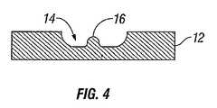
キノコ形の先端9およびB字形の先端10を形成するためのアンビル12は、ここで図3および4を参照して議論される。図3は、アンビル12の平面図を示し、図4は、横断線4をに沿ったその断面図を示す。このアンビル12は、この先端4の周りにフィットするように構成された深さおよび縁を有するくぼみ14を備える。このくぼみ14は、必要に応じて、くぼみ14の中心に配置される割裂器16を備えていてもよい。この割裂器16は、先端4の特定の外形を達成するために使用され得る。 An
このくぼみ14は、先端4と相互に作用するように形作られており、この先端4を望ましい変形した形(例えば、キノコ形の先端9)に形成するように形作られている。例示された実施形態において、このくぼみ14は、実質的に丸い形状を有し、ここでこの縁は、先端4の拡大を制限する。このくぼみ14の縁および深さは、シャフト8の長さおよび固定されるべき組織の厚みに依存して、それに合うように変動する。よって、先端4がくぼみ14と相互に作用し、圧力が先端に付与されるにつれて、この先端4は、キノコ形の先端9へと形成され、ここでこのキノコ形の先端9は、くぼみ14の縁を越えて拡がらない。キノコ形の先端9はまた、割裂器16を用いて形成され得る。ここでこの割裂器16は、全ての方向に一様に先端4を割裂する。割裂器16の形状は、望ましい形状に変形される先端に依存する。キノコ形の先端9にされるべき場合、割裂器16は、先端4を全ての方向に割裂するように構成された点状先端(point−like tip)を有する。B字形の先端10にされるべき場合、割裂器16は、2方向にのみ、実質的に均等に先端4を割裂するように構成された刃物様先端を有する。キノコ形の先端9の作製は、平らにされたアンビルなどを用いて形成され得る。割裂器16は、望ましい止血を達成するために、先端4を3つ、4つ、5つなどのセグメント(これは、均等にまたは不均等に割裂されてもよく、かつ/またはあらゆる数の方向に向いていてもよい)に割裂するために適した種々のピラミッド形状を有し得ることもまた、想定される。 The
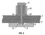
図5に示されるように、アンビル12は、リベット2の先端4と接触している。ここでこの割裂器16は、先端4をキノコ形の先端9に形成する。アンビル12によって圧力が付与されながら、反作用力が頭部6に付与される。 As shown in FIG. 5, the
リベット2の代替的実施形態が示される、図5および6において認められるように、リベット2は、頭部6とばね板20との間に配置された、複数のベルビルワッシャー(Belleville washer)22を備える。ベルビルワッシャー22はまた、コップ状ばねワッシャー(cupped spring washer)として公知であり、平らでないワッシャーの1つのタイプである。ワッシャー22は、わずかな円錐形を有し、この形は、ワッシャー22にばね特性を与える。ワッシャー22は、ばねとして使用されるか、またはリベット2に予め荷重を付与するかもしくは可撓性の性質を付与するために使用される。当業者は、他のタイプのばね様構造体(例えば、ばね)が、リベット2に柔軟な荷重性質を提供するために使用され得ることを理解する。 As can be seen in FIGS. 5 and 6, where an alternative embodiment of the
ワッシャー22は、図7Aに示されるように、板20と頭部6との間で圧迫される場合に平らになり、それにより、リベット2が、より厚い組織Tを貫通し、一方では十分な圧力をその組織上で維持することを可能にする。頭部6と板20との間の空間が拡がる場合、ワッシャー22は、それらの本来の円錐形の外形に戻って、組織Tに対して圧力を維持し続け、かつリベット2を適所に固定しようとする。このワッシャー22は、種々の厚みにわたって、組織Tに対して実質的に一定の力を維持しする。形成される先端(例えば、キノコ形の先端9およびB字形の先端10)の種々のサイズおよび/または直径と組み合わせると、リベット2は、種々の厚みの組織Tに適合することができ、この組織を固定することができる。他の圧迫機構(例えば、ばね)が使用され得、この機構は、リベット2が組織に挿入された後に、その組織に対して圧力を維持する。図7Cにおいて認められるように、キノコ形の先端9は、図2A〜2Bを参照しながら上記で議論されるように、B字形の先端10で置き換えられ得る。 The
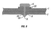
図8は、医療用リベット2の別の実施形態を示す。その先端9は、その先端9を変形かつ/または変化させることなく、組織Tに対して固定される。代わりに、この医療用リベット2は、このリベット2がワッシャー32を先端9の上にスライドさせることによって、その組織を貫通した後に組織Tの第1表面と第2表面に固定される。ワッシャー32は、2つ以上のロッキング部材30によって組織に固定される。そのロッキング部材30は、突出部またはフィンガージョイントであり得る。このロッキング部材は、ワッシャー32が一方向に(例えば、頭部6に向かって)スライドでき、一旦ワッシャー32が、ロッキング部材30を超えて挿入されると、滑り落ちないように適合されている。このロッキング部材30は、固定される組織のサイズに依存して、シャフト8の長さに沿ってどこにでも配置され得る。種々の厚みの組織で容易にするために、1つ以上のばね様構造体(例えば、ベルビルワッシャー22)を、種々の厚みにわたって組織Tに対して実質的に一定の力を維持するために使用され得る。 FIG. 8 shows another embodiment of the
本開示の記載される実施形態は、限定するというよりも例示であることが意図され、本開示の全ての実施形態を表すことを意図しているのではない。種々の改変およびバリエーションが、添付の特許請求の範囲において文言上示されるかまたは法的に均等であることが示されるような、開示の趣旨または範囲を逸脱することなく行われ得る。 The described embodiments of the present disclosure are intended to be illustrative rather than limiting, and are not intended to represent every embodiment of the present disclosure. Various modifications and variations may be made without departing from the spirit or scope of the disclosure as set forth in the appended claims as indicated by wording or legal equivalent.
(摘要)
組織を固定しかつ組織に止血をもたらすための医療用ファスナーが開示される。このファスナーは、近位端と遠位端とを有するシャフト、および近位端に配置された頭部、および遠位端に配置された先端を備える。その先端は、その組織を貫通しかつキノコ形の先端もしくは変形B字形の先端を形成して、ファスナーを組織に固定するように構成されている。(Summary)
A medical fastener for securing tissue and providing hemostasis to the tissue is disclosed. The fastener includes a shaft having a proximal end and a distal end, a head disposed at the proximal end, and a tip disposed at the distal end. The tip is configured to penetrate the tissue and form a mushroom-shaped tip or a deformed B-shaped tip to secure the fastener to the tissue.
本開示の上記および他の局面、特徴および利点は、添付の図面とともに解釈した場合、以下の詳細な説明に鑑みてより明らかになる。
Claims (17)
Translated fromJapanese近位端と遠位端とを有するシャフトを備える少なくとも1つのリベットであって、該リベットは、該近位端に頭部と、該遠位端に先端とをさらに有し、ここで該先端は、組織貫通に適した形状を有し、かつ該第1表面および該第2表面を通して組織を貫通するために適合されている、リベット;ならびに
アンビルであって、該先端と相互に作用するように適合され、かつ該先端に圧力を付与すると、該先端の形状を変化させて、該第1表面と接触している該頭部と、該第2表面と接触している該先端との間に組織を固定するように適合された、くぼみを有する、アンビル
を備える、システム。A system for sealing tissue having a first surface and a second surface, the system comprising:
At least one rivet comprising a shaft having a proximal end and a distal end, the rivet further comprising a head at the proximal end and a tip at the distal end, wherein the tip A rivet having a shape suitable for tissue penetration and adapted to penetrate tissue through the first surface and the second surface; and an anvil, wherein the anvil interacts with the tip And applying pressure to the tip changes the shape of the tip between the head in contact with the first surface and the tip in contact with the second surface. A system comprising an anvil having an indentation adapted to secure tissue thereto.
近位端と遠位端とを有する、シャフト;
該シャフトの近位端に配置された、頭部;
該シャフトの遠位端に配置された、先端であって、ここで該先端は、組織貫通に適した形状を有し、かつ該第1表面および該第2表面を通して組織を貫通するために適合されており、該先端の形状は、該先端に圧力を付与すると変化して、該第1表面と接触している該頭部と、該第2表面と接触している該先端との間に組織を固定するために適合されている、先端、
を備える、医療用リベット。A medical rivet for sealing tissue having a first surface and a second surface, the rivet comprising:
A shaft having a proximal end and a distal end;
A head disposed at a proximal end of the shaft;
A tip disposed at the distal end of the shaft, wherein the tip has a shape suitable for tissue penetration and is adapted to penetrate tissue through the first surface and the second surface And the shape of the tip changes when pressure is applied to the tip, and between the head in contact with the first surface and the tip in contact with the second surface. A tip, which is adapted to fix tissue
A medical rivet comprising:
近位端と遠位端とを有するシャフト;
該シャフトの近位端に配置された頭部;
該シャフトの遠位端に配置された先端であって、ここで該先端は、組織貫通に適した形状を有し、かつ該第1表面および該第2表面を通して該組織を貫通するように適合されている、先端;
複数のロッキング部材であって、該シャフトにはめ込まれたワッシャーを固定し、それによって該第1表面と接触している該頭部と、該第2表面と接触している該ワッシャーとの間に該組織を固定するように適合されている、複数のロッキング部材、
を備える、医療用リベット。A medical rivet for sealing tissue having a first surface and a second surface, the rivet comprising:
A shaft having a proximal end and a distal end;
A head located at the proximal end of the shaft;
A tip disposed at the distal end of the shaft, wherein the tip has a shape suitable for tissue penetration and is adapted to penetrate the tissue through the first surface and the second surface Being the tip;
A plurality of locking members, wherein a washer fitted into the shaft is fixed so that the head is in contact with the first surface and the washer in contact with the second surface. A plurality of locking members adapted to secure the tissue;
A medical rivet comprising:
Applications Claiming Priority (1)
| Application Number | Priority Date | Filing Date | Title |
|---|---|---|---|
| US68707405P | 2005-06-03 | 2005-06-03 |
Publications (1)
| Publication Number | Publication Date |
|---|---|
| JP2006334414Atrue JP2006334414A (en) | 2006-12-14 |
Family
ID=36884378
Family Applications (1)
| Application Number | Title | Priority Date | Filing Date |
|---|---|---|---|
| JP2006155442APendingJP2006334414A (en) | 2005-06-03 | 2006-06-02 | System and method for sealing tissue |
Country Status (7)
| Country | Link |
|---|---|
| US (1) | US20060282084A1 (en) |
| EP (1) | EP1728474B1 (en) |
| JP (1) | JP2006334414A (en) |
| AU (1) | AU2006202349A1 (en) |
| CA (1) | CA2549220A1 (en) |
| DE (1) | DE602006008215D1 (en) |
| ES (1) | ES2330244T3 (en) |
Cited By (2)
| Publication number | Priority date | Publication date | Assignee | Title |
|---|---|---|---|---|
| JP2010515548A (en)* | 2007-01-12 | 2010-05-13 | エシコン エンド−サージェリー,インク. | Variable compression staple and stapling method by variable compression |
| JP2019501696A (en)* | 2015-12-07 | 2019-01-24 | マイクロ インターベンショナル デバイシズ,インコーポレイティド | Fixing the prosthesis to the tissue |
Families Citing this family (20)
| Publication number | Priority date | Publication date | Assignee | Title |
|---|---|---|---|---|
| US7959050B2 (en)* | 2005-07-26 | 2011-06-14 | Ethicon Endo-Surgery, Inc | Electrically self-powered surgical instrument with manual release |
| US9662116B2 (en) | 2006-05-19 | 2017-05-30 | Ethicon, Llc | Electrically self-powered surgical instrument with cryptographic identification of interchangeable part |
| US8627993B2 (en) | 2007-02-12 | 2014-01-14 | Ethicon Endo-Surgery, Inc. | Active braking electrical surgical instrument and method for braking such an instrument |
| US11751873B2 (en) | 2005-07-26 | 2023-09-12 | Cilag Gmbh International | Electrically powered surgical instrument with manual release |
| US8627995B2 (en)* | 2006-05-19 | 2014-01-14 | Ethicon Endo-Sugery, Inc. | Electrically self-powered surgical instrument with cryptographic identification of interchangeable part |
| US9554803B2 (en) | 2005-07-26 | 2017-01-31 | Ethicon Endo-Surgery, Llc | Electrically self-powered surgical instrument with manual release |
| US8573462B2 (en) | 2006-05-19 | 2013-11-05 | Ethicon Endo-Surgery, Inc. | Electrical surgical instrument with optimized power supply and drive |
| US10314583B2 (en) | 2005-07-26 | 2019-06-11 | Ethicon Llc | Electrically self-powered surgical instrument with manual release |
| US8579176B2 (en) | 2005-07-26 | 2013-11-12 | Ethicon Endo-Surgery, Inc. | Surgical stapling and cutting device and method for using the device |
| US7479608B2 (en) | 2006-05-19 | 2009-01-20 | Ethicon Endo-Surgery, Inc. | Force switch |
| US8114100B2 (en)* | 2006-12-06 | 2012-02-14 | Ethicon Endo-Surgery, Inc. | Safety fastener for tissue apposition |
| AU2011218702B2 (en)* | 2007-01-12 | 2013-06-06 | Ethicon Endo-Surgery, Inc | Adjustable compression staple and method for stapling with adjustable compression |
| US20080287989A1 (en)* | 2007-05-17 | 2008-11-20 | Arch Day Design, Llc | Tissue holding implants |
| US9017382B2 (en)* | 2008-05-19 | 2015-04-28 | Ams Research Corporation | Collapsible tissue anchor device and method |
| USD603045S1 (en) | 2009-03-13 | 2009-10-27 | Orthopedic Development Corporation | Surgical dilator |
| US10959840B2 (en) | 2010-01-20 | 2021-03-30 | Micro Interventional Devices, Inc. | Systems and methods for affixing a prosthesis to tissue |
| US9888920B2 (en) | 2010-09-21 | 2018-02-13 | Sportwelding Gmbh | Connecting a plurality of tissue parts |
| US9168076B2 (en)* | 2011-01-25 | 2015-10-27 | Bridging Medical, Llc | Bone compression screw |
| WO2016081528A1 (en) | 2014-11-17 | 2016-05-26 | Bridging Medical, Llc | Bone compression systems |
| CN111420402B (en) | 2020-03-18 | 2021-05-14 | 腾讯科技(深圳)有限公司 | Virtual environment picture display method, device, terminal and storage medium |
Citations (4)
| Publication number | Priority date | Publication date | Assignee | Title |
|---|---|---|---|---|
| US20020026216A1 (en)* | 1999-10-13 | 2002-02-28 | Grimes Randall Y. | Devices and methods for percutaneous mitral valve repair |
| JP2002516698A (en)* | 1998-06-04 | 2002-06-11 | ジンテーズ アクチエンゲゼルシャフト クール | Surgical blind rivet with closure element |
| US20030069603A1 (en)* | 2001-10-10 | 2003-04-10 | Little James S. | Medical tack with a variable effective length |
| JP2005524478A (en)* | 2002-05-06 | 2005-08-18 | ドレクセル ユニバーシティー | Tissue anastomosis device capable of delivering bioactive agent and method using the same |
Family Cites Families (51)
| Publication number | Priority date | Publication date | Assignee | Title |
|---|---|---|---|---|
| US371884A (en)* | 1887-10-18 | Metal seal | ||
| US1934780A (en)* | 1930-04-14 | 1933-11-14 | Motor Wheel Corp | Method of riveting wood and metal elements |
| US1966401A (en)* | 1931-05-25 | 1934-07-10 | Smith Corp A O | Rivet |
| US2654272A (en)* | 1949-07-16 | 1953-10-06 | Warren Walter Wallace Donald | Riveting process |
| US3009381A (en)* | 1957-11-27 | 1961-11-21 | Illinois Tool Works | Stud and dished plastic fastening element |
| GB1289172A (en)* | 1969-07-03 | 1972-09-13 | ||
| US3810279A (en)* | 1973-02-28 | 1974-05-14 | Illinois Tool Works | Plastic drive fastener |
| US4142154A (en)* | 1977-09-16 | 1979-02-27 | General Dynamics Corporation | Hole tester using a permeable protective sleeve insertible in said hole and adapted to receive a relatively movable eddy current probe |
| US4747739A (en)* | 1979-01-15 | 1988-05-31 | Bowman Harold M | Ingot mold and method |
| JPS6017527Y2 (en)* | 1980-09-22 | 1985-05-29 | 株式会社ニフコ | plastic fasteners |
| US4478543A (en)* | 1982-01-25 | 1984-10-23 | Microdot Inc. | Blind rivet |
| US4478544A (en)* | 1982-06-04 | 1984-10-23 | Microdot Inc. | Composite rivet |
| US4532926A (en)* | 1983-06-20 | 1985-08-06 | Ethicon, Inc. | Two-piece tissue fastener with ratchet leg staple and sealable latching receiver |
| US4653486A (en)* | 1984-04-12 | 1987-03-31 | Coker Tom P | Fastener, particularly suited for orthopedic use |
| US4646741A (en)* | 1984-11-09 | 1987-03-03 | Ethicon, Inc. | Surgical fastener made from polymeric blends |
| US4749323A (en)* | 1985-12-02 | 1988-06-07 | Lockheed Corporation | Hole expanding rivet with a shaded tail |
| US4761871A (en)* | 1986-11-21 | 1988-08-09 | Phillips Petroleum Company | Method of joining two thermoplastic articles |
| GB2205374B (en)* | 1987-05-19 | 1991-03-27 | Rockwell International Corp | Composite fasteners & method for fastening structural components therewith |
| US5261914A (en)* | 1987-09-02 | 1993-11-16 | Russell Warren | Surgical fastener |
| US5195859A (en)* | 1990-08-20 | 1993-03-23 | The Glasscrew Company | Fastener for joining a plurality of layers |
| US5725529A (en)* | 1990-09-25 | 1998-03-10 | Innovasive Devices, Inc. | Bone fastener |
| ATE174777T1 (en)* | 1990-09-25 | 1999-01-15 | Innovasive Devices Inc | BONE FIXATION DEVICE |
| US7074203B1 (en)* | 1990-09-25 | 2006-07-11 | Depuy Mitek, Inc. | Bone anchor and deployment device therefor |
| US5480403A (en)* | 1991-03-22 | 1996-01-02 | United States Surgical Corporation | Suture anchoring device and method |
| CA2063159C (en)* | 1991-03-22 | 1999-06-15 | Thomas W. Sander | Orthopedic fastener |
| US5290281A (en)* | 1992-06-15 | 1994-03-01 | Medicon Eg | Surgical system |
| US5522843A (en)* | 1994-02-23 | 1996-06-04 | Orthopaedic Biosystems Limited, Inc. | Apparatus for attaching soft tissue to bone |
| US5482463A (en)* | 1994-04-08 | 1996-01-09 | Wilson, Jr.; Richard S. | Anti-slippage mechanism for dental implant components |
| US5566926A (en)* | 1994-08-19 | 1996-10-22 | Voight Products Incorporated | Resilient safety barrier |
| US5948000A (en)* | 1996-10-03 | 1999-09-07 | United States Surgical Corporation | System for suture anchor placement |
| CA2217406C (en)* | 1996-10-04 | 2006-05-30 | United States Surgical Corporation | Suture anchor installation system with disposable loading unit |
| US6241732B1 (en)* | 1998-11-03 | 2001-06-05 | David W. Overaker | Biocompatible absorbable rivets and pins for use in surgical procedures |
| US6846313B1 (en)* | 1998-11-03 | 2005-01-25 | Codman & Shurtleff, Inc. | One-piece biocompatible absorbable rivet and pin for use in surgical procedures |
| US6482210B1 (en)* | 1998-11-12 | 2002-11-19 | Orthopaedic Biosystems, Ltd., Inc. | Soft tissue/ligament to bone fixation device with inserter |
| CA2368470C (en)* | 1999-03-25 | 2011-05-17 | Metabolix, Inc. | Medical devices and applications of polyhydroxyalkanoate polymers |
| US6319258B1 (en)* | 1999-09-29 | 2001-11-20 | Ethicon, Inc. | Absorbable rivet/pin applier for use in surgical procedures |
| US6533454B1 (en)* | 1999-09-30 | 2003-03-18 | Bionx Implants Oy | Surgical system for tissue fixation |
| US6273893B1 (en)* | 1999-11-10 | 2001-08-14 | Ethicon, Inc. | Absorbable rivet/pin applier for use in surgical procedures |
| US6610079B1 (en)* | 1999-12-14 | 2003-08-26 | Linvatec Corporation | Fixation system and method |
| US6623492B1 (en)* | 2000-01-25 | 2003-09-23 | Smith & Nephew, Inc. | Tissue fastener |
| US6276883B1 (en)* | 2000-04-03 | 2001-08-21 | John Unsworth | Self adjusting screw system |
| EP1315462B1 (en)* | 2000-09-07 | 2009-07-15 | Synthes GmbH | Device for fixing surgical implants |
| WO2002024081A1 (en)* | 2000-09-22 | 2002-03-28 | Codman & Shurtleff, Inc. | Self centering bone drill |
| US6524328B2 (en)* | 2001-04-12 | 2003-02-25 | Scion International, Inc. | Suture lock, lock applicator and method therefor |
| US6499926B2 (en)* | 2001-05-18 | 2002-12-31 | The Boeing Company | Fastener apparatus and method of fastening non-metallic structures |
| GB0113697D0 (en)* | 2001-06-06 | 2001-07-25 | Smith & Nephew | Fixation devices for tissue repair |
| US6860691B2 (en)* | 2001-06-18 | 2005-03-01 | John Duncan Unsworth | Self adjusting, high strength, screw system |
| WO2003001075A1 (en)* | 2001-06-21 | 2003-01-03 | Black & Decker, Inc. | Explosive assisted expanding fastener |
| US20040030351A1 (en)* | 2002-04-05 | 2004-02-12 | Goldberg Mark C. | Endovascular device for reducing type I leaks from endovascularly-implanted grafts |
| CA2562096A1 (en)* | 2004-05-03 | 2005-11-24 | Ams Research Corporation | Surgical implants and related methods |
| US7351022B2 (en)* | 2004-09-30 | 2008-04-01 | Denslow Clark A | Unified multi-part head for a staked fastener |
- 2006
- 2006-05-31USUS11/444,547patent/US20060282084A1/ennot_activeAbandoned
- 2006-06-01CACA002549220Apatent/CA2549220A1/ennot_activeAbandoned
- 2006-06-02DEDE602006008215Tpatent/DE602006008215D1/enactiveActive
- 2006-06-02EPEP06011498Apatent/EP1728474B1/ennot_activeNot-in-force
- 2006-06-02ESES06011498Tpatent/ES2330244T3/enactiveActive
- 2006-06-02AUAU2006202349Apatent/AU2006202349A1/ennot_activeAbandoned
- 2006-06-02JPJP2006155442Apatent/JP2006334414A/enactivePending
Patent Citations (4)
| Publication number | Priority date | Publication date | Assignee | Title |
|---|---|---|---|---|
| JP2002516698A (en)* | 1998-06-04 | 2002-06-11 | ジンテーズ アクチエンゲゼルシャフト クール | Surgical blind rivet with closure element |
| US20020026216A1 (en)* | 1999-10-13 | 2002-02-28 | Grimes Randall Y. | Devices and methods for percutaneous mitral valve repair |
| US20030069603A1 (en)* | 2001-10-10 | 2003-04-10 | Little James S. | Medical tack with a variable effective length |
| JP2005524478A (en)* | 2002-05-06 | 2005-08-18 | ドレクセル ユニバーシティー | Tissue anastomosis device capable of delivering bioactive agent and method using the same |
Cited By (7)
| Publication number | Priority date | Publication date | Assignee | Title |
|---|---|---|---|---|
| JP2010515548A (en)* | 2007-01-12 | 2010-05-13 | エシコン エンド−サージェリー,インク. | Variable compression staple and stapling method by variable compression |
| JP2014064924A (en)* | 2007-01-12 | 2014-04-17 | Ethicon Endo-Surgery Inc | Adjustable compression staple |
| JP2016027883A (en)* | 2007-01-12 | 2016-02-25 | エシコン エンド−サージェリー,インク. | Variable compression staple |
| JP2017192747A (en)* | 2007-01-12 | 2017-10-26 | エシコン エンド−サージェリー,インク. | Variable compression staple |
| US11877742B2 (en) | 2007-01-12 | 2024-01-23 | Cilag Gmbh International | Adjustable compression staple and method for stapling with adjustable compression |
| JP2019501696A (en)* | 2015-12-07 | 2019-01-24 | マイクロ インターベンショナル デバイシズ,インコーポレイティド | Fixing the prosthesis to the tissue |
| JP7001595B2 (en) | 2015-12-07 | 2022-01-19 | マイクロ インターベンショナル デバイシズ,インコーポレイティド | Fixing the prosthesis to the tissue |
Also Published As
| Publication number | Publication date |
|---|---|
| EP1728474B1 (en) | 2009-08-05 |
| CA2549220A1 (en) | 2006-12-03 |
| AU2006202349A1 (en) | 2006-12-21 |
| ES2330244T3 (en) | 2009-12-07 |
| DE602006008215D1 (en) | 2009-09-17 |
| US20060282084A1 (en) | 2006-12-14 |
| EP1728474A1 (en) | 2006-12-06 |
Similar Documents
| Publication | Publication Date | Title |
|---|---|---|
| JP2006334414A (en) | System and method for sealing tissue | |
| US20060291981A1 (en) | Expandable backspan staple | |
| US9603641B2 (en) | Device for osteosynthesis | |
| US9277909B2 (en) | Suture anchor | |
| US10624636B2 (en) | Surgical stapling device with floating staple cartridge | |
| JP2672713B2 (en) | Surgical equipment | |
| JP5641812B2 (en) | Surgical staples | |
| US10918372B2 (en) | Suture anchor | |
| JP5053386B2 (en) | Bone fragment repositioning and fixation system | |
| US9050077B2 (en) | Suture anchor inserter | |
| EP2320818B1 (en) | Crimp with an insert to hold a cable | |
| US20040193188A1 (en) | Laminated surgical clip | |
| JP2012526610A (en) | Re-adjustable fixing plate hole | |
| US20080287989A1 (en) | Tissue holding implants | |
| WO2007108074A1 (en) | Bone graft plate | |
| US20230309988A1 (en) | Suture anchor | |
| US11272916B2 (en) | Systems, devices and methods for affixing soft tissue to bone | |
| JP7701043B2 (en) | Bone Fixation Plate System | |
| US20220054176A1 (en) | Bone fixation system and method |
Legal Events
| Date | Code | Title | Description |
|---|---|---|---|
| A621 | Written request for application examination | Free format text:JAPANESE INTERMEDIATE CODE: A621 Effective date:20090401 | |
| A131 | Notification of reasons for refusal | Free format text:JAPANESE INTERMEDIATE CODE: A131 Effective date:20110506 | |
| A02 | Decision of refusal | Free format text:JAPANESE INTERMEDIATE CODE: A02 Effective date:20111017 |