JP2006334029A - Surgical surgical device - Google Patents
Surgical surgical deviceDownload PDFInfo
- Publication number
- JP2006334029A JP2006334029AJP2005160623AJP2005160623AJP2006334029AJP 2006334029 AJP2006334029 AJP 2006334029AJP 2005160623 AJP2005160623 AJP 2005160623AJP 2005160623 AJP2005160623 AJP 2005160623AJP 2006334029 AJP2006334029 AJP 2006334029A
- Authority
- JP
- Japan
- Prior art keywords
- switch
- set value
- output
- output set
- handpiece
- Prior art date
- Legal status (The legal status is an assumption and is not a legal conclusion. Google has not performed a legal analysis and makes no representation as to the accuracy of the status listed.)
- Pending
Links
Images


Classifications
- A—HUMAN NECESSITIES
- A61—MEDICAL OR VETERINARY SCIENCE; HYGIENE
- A61B—DIAGNOSIS; SURGERY; IDENTIFICATION
- A61B17/00—Surgical instruments, devices or methods
- A61B17/32—Surgical cutting instruments
- A61B17/320068—Surgical cutting instruments using mechanical vibrations, e.g. ultrasonic
- A61B17/320092—Surgical cutting instruments using mechanical vibrations, e.g. ultrasonic with additional movable means for clamping or cutting tissue, e.g. with a pivoting jaw
- A—HUMAN NECESSITIES
- A61—MEDICAL OR VETERINARY SCIENCE; HYGIENE
- A61B—DIAGNOSIS; SURGERY; IDENTIFICATION
- A61B17/00—Surgical instruments, devices or methods
- A61B2017/00017—Electrical control of surgical instruments
- A61B2017/00199—Electrical control of surgical instruments with a console, e.g. a control panel with a display
- A—HUMAN NECESSITIES
- A61—MEDICAL OR VETERINARY SCIENCE; HYGIENE
- A61B—DIAGNOSIS; SURGERY; IDENTIFICATION
- A61B17/00—Surgical instruments, devices or methods
- A61B2017/00477—Coupling
- A61B2017/00482—Coupling with a code
- A—HUMAN NECESSITIES
- A61—MEDICAL OR VETERINARY SCIENCE; HYGIENE
- A61B—DIAGNOSIS; SURGERY; IDENTIFICATION
- A61B17/00—Surgical instruments, devices or methods
- A61B2017/00973—Surgical instruments, devices or methods pedal-operated
Landscapes
- Health & Medical Sciences (AREA)
- Surgery (AREA)
- Engineering & Computer Science (AREA)
- Life Sciences & Earth Sciences (AREA)
- Heart & Thoracic Surgery (AREA)
- Nuclear Medicine, Radiotherapy & Molecular Imaging (AREA)
- Mechanical Engineering (AREA)
- Biomedical Technology (AREA)
- Dentistry (AREA)
- Medical Informatics (AREA)
- Molecular Biology (AREA)
- Animal Behavior & Ethology (AREA)
- General Health & Medical Sciences (AREA)
- Public Health (AREA)
- Veterinary Medicine (AREA)
- Surgical Instruments (AREA)
Abstract
Translated fromJapaneseDescription
Translated fromJapaneseこの発明は、外科用手術時の各種機器に対する電力供給などの際に使用される外科用手術装置に関する。 The present invention relates to a surgical operation apparatus used for supplying power to various devices during surgical operation.
特許文献1には、複数の医療機器を1つのリモコンで効率的かつ確実に操作することが可能な内視鏡システムが開示されている。このシステムは、リモコンに複数のファンクションスイッチとELパネルと文字透過部とからなる複数の機器名表示部および機能設定部を形成している。そして、このシステムは、使用する機器のみ機能表示部を発光させるようにCPUがELパネルの発光を制御することができる。このため、患者の術部以外が比較的暗い手術室であってもリモコンの表示を確実に視認可能である。 Patent Document 1 discloses an endoscope system that can efficiently and surely operate a plurality of medical devices with a single remote controller. In this system, a plurality of device name display units and function setting units each including a plurality of function switches, an EL panel, and a character transmission unit are formed on the remote controller. In this system, the CPU can control the light emission of the EL panel so that only the device to be used causes the function display unit to emit light. For this reason, the display on the remote controller can be reliably visually recognized even in a relatively dark operating room other than the surgical site of the patient.
特許文献2には、術者が実際に把持したハンドピースから処置出力が可能となるように選択可能にした操作性の良い外科手術システムが開示されている。このシステムは、複数のハンドピースの把持部に設けた保持検出手段と、保持検出手段の検出信号に基づきハンドピース接続部に対して駆動信号の出力を切り替える出力切替手段とを備えている。そして、このシステムは、操作後にリモートスイッチの選択スイッチ付近のLEDが発光したり、装置本体の操作パネル上の選択スイッチ近傍に設けたLEDが発光したりすることで選択結果(操作結果)を告知することができる。 Patent Document 2 discloses a surgical system with good operability that can be selected so that treatment output can be performed from a handpiece that is actually grasped by an operator. This system includes holding detection means provided in the gripping portions of a plurality of handpieces, and output switching means for switching the output of the drive signal to the handpiece connection section based on the detection signal of the holding detection means. In this system, after the operation, the LED near the selection switch of the remote switch emits light, or the LED provided near the selection switch on the operation panel of the device main body emits light to notify the selection result (operation result). can do.
特許文献3には、複数の装置を使用する接続装置識別システムにおいて、どの装置がどのケーブル/コードによってどの端子と接続されているのか装置側で識別し、配線状態を容易に確認するシステムが開示されている。このシステムは、装置同士の接続を認識するとともに接続状態を告知する接続認識手段とを備えている。液晶表示部には、目的の各装置の状態表示や操作スイッチなどを設定画面として表示する表示機能とともに、タッチセンサの所定領域を触れることで操作スイッチによる操作を行なう操作機能を備えている。
特許文献1に記載のシステムでは、複数の機器が接続される手術システムにおいて、リモコンに機能表示部を発光させ使用可能機器を示している。ここでは、患者の術部以外が比較的暗い手術室でのリモコンの表示を確実に視認可能である。また、特許文献2に記載のシステムでは、複数のハンドピースが接続される手術システムにおいて、操作可能なハンドピースを明示している。しかし、特許文献1や特許文献2に開示されたシステムでは、設定に使用するスイッチが多数存在する場合があり、どのスイッチを操作すれば良いのか、分かり難い場合がある。 In the system described in Patent Literature 1, in a surgical system in which a plurality of devices are connected, a function display unit is caused to emit light and a usable device is indicated. Here, the display on the remote control in the operating room, which is relatively dark except for the patient's surgical site, can be reliably recognized. Moreover, in the system described in Patent Document 2, an operable handpiece is clearly shown in a surgical system to which a plurality of handpieces are connected. However, in the systems disclosed in Patent Document 1 and Patent Document 2, there are cases where there are a large number of switches used for setting, and it may be difficult to know which switch to operate.
また、特許文献3に記載のシステムでは、複数の機器が接続される手術システムにおいて、液晶表示部に目的の各装置の状態表示や操作スイッチなどを設定画面として表示する表示機能およびタッチセンサを有している。しかし、タッチセンサは押圧スイッチに比べて感度が劣ることが一般的である。すなわち、感度によってはスイッチを作動させる際に何度も同じ操作を必要とする場合がある。 Further, the system described in Patent Document 3 has a display function and a touch sensor for displaying a status display of each target device and operation switches as a setting screen on a liquid crystal display unit in a surgical system in which a plurality of devices are connected. is doing. However, the touch sensor is generally less sensitive than the push switch. That is, depending on the sensitivity, the same operation may be required many times when the switch is operated.
この発明は、このような課題を解決するためになされたものであり、その目的とするところは、ユーザが効率的に機器の設定等の操作を行なえる、操作性の良い外科用手術装置を提供することにある。 This invention is made in order to solve such a subject, The place made into the objective is the surgical operation apparatus with sufficient operativity in which a user can perform operation, such as an apparatus setting, efficiently. It is to provide.
上記課題を解決するために、この発明に係る外科用手術装置は、手術装置本体と、この手術装置本体に設けられ、ユーザに操作される複数のスイッチと、前記スイッチもしくはこれらスイッチの周辺をそれぞれ発光させる発光部と、前記手術装置本体に設けられた制御部と、この制御部に接続されているとともに前記スイッチに接続され、前記スイッチのうち、ユーザが操作可能なスイッチを検知する検知部と、前記制御部に接続され、前記検知部からの信号に基づいて操作可能なスイッチの発光部を発光させる発光回路とを備えていることを特徴とする。 In order to solve the above-described problems, a surgical operation apparatus according to the present invention includes a surgical apparatus main body, a plurality of switches provided in the surgical apparatus main body and operated by a user, and the switches or the periphery of these switches. A light emitting unit that emits light, a control unit provided in the surgical apparatus main body, a detection unit that is connected to the control unit and connected to the switch, and detects a switch that can be operated by a user among the switches; And a light-emitting circuit that is connected to the control unit and that emits light from a light-emitting unit of a switch that can be operated based on a signal from the detection unit.
このため、例えばハンドピースなどの機器が手術装置本体に接続されている状態において、ユーザが操作可能なスイッチを発光部を発光等させて明示することにより、ユーザが効率的に機器の設定等の操作を行なうことができる。 For this reason, for example, when a device such as a handpiece is connected to the surgical apparatus main body, the user can efficiently set the device by clearly indicating the switch that can be operated by the light emitting unit to emit light. The operation can be performed.
また、上記課題を解決するために、この発明に係る外科用手術装置は、手術装置本体と、この手術装置本体に設けられ、ユーザに操作される複数のスイッチと、前記スイッチもしくはこれらスイッチの周辺をそれぞれ発光させる発光手段と、前記手術装置本体に設けられ、前記スイッチのうち、ユーザが操作可能なスイッチを認識する認識手段と、前記認識手段の認識結果に基づいて前記発光手段を発光させる電力を供給する電力供給制御手段とを備えていることを特徴とする。 In order to solve the above-described problems, a surgical operation apparatus according to the present invention includes a surgical apparatus main body, a plurality of switches provided in the surgical apparatus main body and operated by a user, and the switches or the periphery of these switches. A light emitting means for emitting light, a recognition means for recognizing a switch operable by a user among the switches, and a power for causing the light emitting means to emit light based on a recognition result of the recognition means Power supply control means for supplying power.
このため、例えばハンドピースなどの機器が手術装置本体に接続されている状態において、ユーザが操作可能なスイッチを発光手段を発光等させて明示することにより、ユーザが効率的に機器の設定等の操作を行なうことができる。 For this reason, for example, when a device such as a handpiece is connected to the surgical apparatus main body, the user can set the device efficiently by clearly indicating the switch that can be operated by the light emitting means to emit light. The operation can be performed.
この発明によれば、ユーザが効率的に機器の設定等の操作を行なえる、操作性の良い外科用手術装置を提供することができる。 According to the present invention, it is possible to provide a surgical operation apparatus with good operability in which a user can efficiently perform operations such as setting of devices.
以下、図面を参照しながらこの発明を実施するための最良の形態(以下、実施の形態という)について説明する。 The best mode for carrying out the present invention (hereinafter referred to as an embodiment) will be described below with reference to the drawings.
第1の実施の形態について図1ないし図5を用いて説明する。 A first embodiment will be described with reference to FIGS.
図1に示すように、外科用手術システム10は、外科用手術装置である超音波振動駆動装置12と、術者に超音波処置を行なうための器具であるハンドピース14と、このハンドピース14から超音波振動を発するか否かを制御するフットスイッチ16とを備えている。このうち、超音波駆動装置12は、他機器18(図3参照)の電源装置としても使用可能である。なお、他機器18としては、図示しないが、例えば高周波電流出力装置、送水器、送気器などがある。 As shown in FIG. 1, a
図2に示すように、超音波駆動装置12は、本体22と、電源スイッチ24と、ハンドピース接続部26と、表示部28と、各種設定スイッチ30と、発光部(発光手段)32と、通信部34とを備えている。これら電源スイッチ24、ハンドピース接続部26、表示部28、各種設定スイッチ30、発光部32および通信部34は、それぞれ本体22に配設されている。 As shown in FIG. 2, the
表示部28には液晶ディスプレイ、有機ELや7セグメント発光ダイオード(LED)などが用いられている。各種設定スイッチ30には押圧スイッチ、圧力スイッチや光スイッチなどが用いられている。発光部32にはLEDなどが用いられている。これら発光部32は、各種設定スイッチ30もしくはその周辺部に配置されている。 As the
図3に示すように、超音波駆動装置12の本体22の内部には、制御回路42と、他機器18との通信部34を通して接続される通信回路44と、ハンドピース検知回路46と、出力回路48と、表示回路50と、スイッチ検知回路(スイッチ認識手段)52と、発光部回路(発光手段)54とが配設されている。制御回路42には、フットスイッチ16(図1参照)、通信回路44、ハンドピース検知回路46、出力回路48、表示回路50、スイッチ検知回路52および発光部回路54が接続されている。このため、制御回路42は、フットスイッチ16からの信号、通信回路44からの他機器18の信号、ハンドピース検知回路46からの接続されているハンドピース14の種類(機種、型式等)の信号、および、スイッチ検知回路52からのスイッチ信号を受けて、通信回路44、表示回路50および発光部回路54にそれぞれ信号を伝達する。 As shown in FIG. 3, inside the
表示回路50および発光部回路54は液晶ディスプレイドライバ、LEDドライバなどを備えている。これら表示回路50および発光部回路54は、制御回路42からの信号を受けて、液晶ディスプレイ、有機ELディスプレイや7セグメントLEDおよびLEDを駆動させる。液晶ディスプレイ、有機ELディスプレイや7セグメントLEDおよびLEDは、単色発光(白黒表示)、複色発光(カラー表示)、変色、点滅が可能である。 The
この実施の形態に係る超音波駆動装置12の設定スイッチ30としては、出力設定値UPスイッチ62aと、出力設定値DOWNスイッチ62bとが配設されている。出力設定値UPスイッチ62aの周囲には発光部32aが配設されている。出力設定値DOWNスイッチ62bの周囲には発光部32bが配設されている。図4に示すように、超音波駆動装置12のハンドピース接続部26には、第1のハンドピース14aが接続されている。第1のハンドピース14aが接続された状態では、超音波駆動装置12の出力設定値を変化させることが可能である。 As the setting switch 30 of the
なお、第1のハンドピース14aと機種や型式等の仕様が異なる第2のハンドピース14bがハンドピース接続部26に接続された状態では、その第2のハンドピース14bから超音波振動を発振できないように超音波駆動装置12の制御回路42および出力回路48が設定されているものとする。 It should be noted that ultrasonic vibration cannot be generated from the
次に、この実施の形態に係る外科用手術システム10の作用について説明する。 Next, the operation of the
電源スイッチ24をONに切り替える(電源スイッチ24を投入する)。ハンドピース検知回路46が第1のハンドピース14aがハンドピース接続部26に接続されていることを検知すると、その検知信号を制御回路42に伝達する。制御回路42は、第1のハンドピース14aに出力を行なって良い旨の信号を出力回路48に伝達する。出力回路48は、第1のハンドピース14aに超音波振動を生じさせるための準備を行なう。なお、このとき、制御回路42は、スイッチ検知回路52からの表示回路50に対して信号を伝達し、表示部28で第1のハンドピース14aに発する現在の出力設定値などを表示する(図示せず)。 Switch on the power switch 24 (turn on the power switch 24). When the
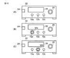
電源スイッチ24を投入した状態では、超音波駆動装置12の出力設定値が最小値である。このとき、超音波駆動装置12の出力設定値が最小値であるため、出力設定値をさらに小さくすることはできない。したがって、出力設定値UPスイッチ62aおよび出力設定値DOWNスイッチ62bのうち、出力設定値UPスイッチ62aのみ操作可能である。このため、図5(A)に示すように、出力設定値UPスイッチ62aの周囲の発光部32aのみが点灯し、出力設定値DOWNスイッチ62bの周囲の発光部32bは消灯し続けている。すなわち、操作可能なスイッチの周囲の発光部32aのみ点灯する。 When the
この状態から超音波駆動装置12の出力設定値UPスイッチ62aを操作して出力設定値を上昇させる。このとき、出力設定値を再び小さくすることもでき、さらに大きくすることもできる。したがって、出力設定値UPスイッチ62aおよび出力設定値DOWNスイッチ62bの両者を操作可能である。このため、図5(B)に示すように、出力設定値UPスイッチ62aの周囲の発光部32aおよび出力設定値DOWNスイッチ62bの周囲の発光部32bの両者が点灯している。すなわち、出力設定値UPスイッチ62aは引き続き点灯した状態を保ち、出力設定値DOWNスイッチ62bの発光部32bは新たに点灯する。このとき、表示部28には、出力設定値が最小の状態から上昇した状態を表示する。 From this state, the output set value is increased by operating the output set
さらに、この状態から超音波駆動装置12の出力設定値を上昇させ、出力設定値を最大値に設定する。このとき、超音波駆動装置12の出力設定値が最大値であるため、出力設定値をさらに大きくすることはできない。したがって、図5(C)に示すように、出力設定値UPスイッチ62aおよび出力設定値DOWNスイッチ62bのうち、出力設定値DOWNスイッチ62bのみ操作可能である。このため、出力設定値DOWNスイッチ62bの周囲の発光部32bのみが点灯し続け、出力設定値UPスイッチ62aの周囲の発光部32aは消灯する。このとき、表示部28には、出力設定値が最大の状態にあることを表示する。 Furthermore, the output set value of the
第1のハンドピース14aを使用する際には、出力設定値UPスイッチ62aおよび出力設定値DOWNスイッチ62bのうち、点灯しているスイッチを操作して、出力設定値を設定する。このとき、ユーザは、出力設定値を表示部28で確認し、上述した操作を行なって所望の出力設定値に設定する。ユーザは第1のハンドピース14aを保持して、超音波駆動装置12に接続されたフットスイッチ16を操作してその信号を制御回路42に伝達する。制御回路42は、出力回路48に対して出力させる信号を伝達する。出力を準備していた出力回路48は、第1のハンドピース14aに超音波駆動のための電流を流す。第1のハンドピース14aは、超音波出力を発振して患者等に対して各種の処置を行なう。 When the
フットスイッチ16を離すと、制御回路42にその信号が伝達される。制御回路42は、出力回路48に対して出力を停止させる信号を伝達する。このため、出力回路48から第1のハンドピース14aに流していた電流が停止する。したがって、第1のハンドピース14aから発振していた超音波出力が停止する。 When the
次に、第1のハンドピース14aを第2のハンドピース14bに交換する場合について説明する。
この場合、第1のハンドピース14aをハンドピース接続部26から取り外し、第2のハンドピース14bをハンドピース接続部26に接続する。このとき、ハンドピース接続部26に接続されているのが第1のハンドピース14aではなく、第2のハンドピース14bであるため、超音波駆動装置12の出力設定値を変化させることができない。Next, the case where the
In this case, the
ここでは、ハンドピース検知回路46がハンドピースの種類を検知し、その信号を制御回路42に伝達する。そして、制御回路42から出力回路48に信号を伝達する。このとき、制御回路42は、ハンドピース接続部26に第2のハンドピース14bが接続されていることがハンドピース検知回路46で検知されているので、出力回路48に対してその出力回路48から超音波を駆動させるために出力しない旨の信号を伝達する。 Here, the
したがって、この状態において、出力設定値UPスイッチ62aおよび出力設定値DOWNスイッチ62bを操作することができない。また、操作しても、その操作により出力設定値UPスイッチ62aや出力回路48を変化させることができない。このため、出力設定値UPスイッチ62aおよび出力設定値DOWNスイッチ62bは消灯し続ける。 Therefore, in this state, the output set
なお、他機器18は、通信部34、通信回路44を介して制御回路42に対して双方向に信号を送信しあって、所望の動作をさせる。 The
以上説明したように、この実施の形態によれば以下の効果が得られる。 As described above, according to this embodiment, the following effects can be obtained.
超音波駆動装置12を操作する際、スイッチ62a,62bの周囲の発光部32a,32bの点灯/消灯によって操作可能なスイッチを容易に認識することができる。したがって、ユーザは、効率的に超音波駆動装置12などの機器を操作することができる。 When operating the
また、消灯しているスイッチを操作しようとしても操作することができないので、ユーザは超音波駆動装置12の操作上の誤りなどを容易に認識することができる。 In addition, since the user cannot operate the switch that has been turned off, the user can easily recognize an operational error of the
したがって、複数の機器や様々なハンドピースが超音波振動駆動装置12に接続されている状態で、その超音波振動駆動装置12をユーザが操作する前に操作可能なスイッチを明示することにより、ユーザが効率的に機器の設定等を行なうことができる。 Therefore, in a state where a plurality of devices and various handpieces are connected to the ultrasonic
なお、発光部32a,32bはスイッチ62a,62bの周囲でなく、それぞれの上側や下側にのみ配設されていることも好適である。 Note that it is also preferable that the
次に、第2の実施の形態について説明する。この実施の形態は第1の実施の形態の変形例であって、第1の実施の形態で説明した部材と同一の部材には同一の符号を付し、詳しい説明を省略する。 Next, a second embodiment will be described. This embodiment is a modification of the first embodiment. The same members as those described in the first embodiment are denoted by the same reference numerals, and detailed description thereof is omitted.
この実施の形態では、超音波駆動装置12の出力設定値UPスイッチ62aおよび出力設定値DOWNスイッチ62bの周囲には、発光色を変化させる発光部(表示灯)32a,32bがそれぞれ配設されている。これら発光部32a,32bは、電源スイッチ24の投入時に対して異なる色を発光可能であることが好適である。このため、発光部32a,32bは、電源スイッチ24の投入時と、その投入時に対して色を変化させる状態と、例えば2種類の色を有するLEDなどの発光体を備えていることが好適である。 In this embodiment, light emitting units (indicator lamps) 32a and 32b that change the light emission color are disposed around the output set
次に、この実施の形態に係る外科用手術システム10の作用について説明する。 Next, the operation of the
電源スイッチ24をONに切り替える(電源スイッチ24を投入する)。このとき、出力設定値UPスイッチ62aおよび出力設定値DOWNスイッチ62bは点灯し続ける。電源スイッチ24を投入した状態では、超音波駆動装置12の出力設定値が最小値である。このとき、超音波駆動装置12の出力設定値が最小値であるため、出力設定値をさらに小さくすることはできない。したがって、出力設定値UPスイッチ62aおよび出力設定値DOWNスイッチ62bのうち、出力設定値UPスイッチ62aのみ操作可能である。このため、出力設定値UPスイッチ62aの発光色が変化し、出力設定値DOWNスイッチ62bは電源スイッチ24投入時の点灯状態のまま点灯し続けている。すなわち、操作可能なスイッチのみ点灯状態が電源スイッチ24の投入時に対して変化する。 Switch on the power switch 24 (turn on the power switch 24). At this time, the output set
この状態から超音波駆動装置12の出力設定値UPスイッチ62aを操作して出力設定値を上昇させる。このとき、出力設定値を再び小さくすることもでき、さらに大きくすることもできる。したがって、出力設定値UPスイッチ62aおよび出力設定値DOWNスイッチ62bの両者を操作可能である。このため、出力設定値UPスイッチ62aおよび出力設定値DOWNスイッチ62bの両者の点灯状態が電源スイッチ24の投入時に対して変化している。すなわち、出力設定値UPスイッチ62aは引き続き点灯状態が変化した状態を保ち、出力設定値DOWNスイッチ62bは新たに点灯状態が変化する。 From this state, the output set value is increased by operating the output set
さらに、この状態から超音波駆動装置12の出力設定値を上昇させ、出力設定値を最大値に設定する。このとき、超音波駆動装置12の出力設定値が最大値であるため、出力設定値をさらに大きくすることはできない。したがって、出力設定値UPスイッチ62aおよび出力設定値DOWNスイッチ62bのうち、出力設定値DOWNスイッチ62bのみ操作可能である。このため、出力設定値DOWNスイッチ62bのみの点灯状態が変化した状態を保ち、出力設定値UPスイッチ62aは電源スイッチ24投入時の点灯状態に変化する。 Furthermore, the output set value of the
第1のハンドピース14aを使用する際には、出力設定値UPスイッチ62aおよび出力設定値DOWNスイッチ62bのうち、点灯状態が変化しているスイッチを操作して、出力設定値を設定する。 When the
次に、電源スイッチ24をOFFに切り替える。この状態で第1のハンドピース14aをハンドピース接続部26から取り外し、第2のハンドピース14bをハンドピース接続部26に接続する。このとき、ハンドピース接続部26に接続されているのが第1のハンドピース14aではなく、第2のハンドピース14bであるため、超音波駆動装置12の出力設定値を変化させることができない。したがって、この状態において、出力設定値UPスイッチ62aおよび出力設定値DOWNスイッチ62bを操作することができない。また、操作しても、その操作により出力設定値UPスイッチ62aや出力設定値DOWNスイッチ62bを変化させることができない。このため、出力設定値UPスイッチ62aおよび出力設定値DOWNスイッチ62bは電源スイッチ24投入時の点灯状態を保持し続ける。 Next, the
次に、第3の実施の形態について説明する。この実施の形態は第1および第2の実施の形態の変形例であって、第1および第2の実施の形態で説明した部材と同一の部材には同一の符号を付し、詳しい説明を省略する。 Next, a third embodiment will be described. This embodiment is a modification of the first and second embodiments, and the same members as those described in the first and second embodiments are denoted by the same reference numerals, and detailed description will be given. Omitted.
この実施の形態では、超音波駆動装置12の出力設定値UPスイッチ62aおよび出力設定値DOWNスイッチ62bには、電源スイッチ24投入時の点灯状態と、発光色を発色させて点滅させる発光部(表示灯)32a,32bがそれぞれ配設されている。これら発光部32a,32bは、電源スイッチ24の投入時に対して異なる色を発光可能であることが好適である。このため、発光部32a,32bは、電源スイッチ24の投入時と、その投入時に対して色を変化させる状態と、例えば2種類の色を有するLEDなどの発光体を備えていることが好適である。 In this embodiment, the output setting
次に、この実施の形態に係る外科用手術システム10の作用について説明する。 Next, the operation of the
電源スイッチ24をONに切り替える(電源スイッチ24を投入する)。このとき、出力設定値UPスイッチ62aおよび出力設定値DOWNスイッチ62bは常に点灯し続ける。電源スイッチ24を投入した状態では、超音波駆動装置12の出力設定値が最小値である。このとき、超音波駆動装置12の出力設定値が最小値であるため、出力設定値をさらに小さくすることはできない。したがって、出力設定値UPスイッチ62aおよび出力設定値DOWNスイッチ62bのうち、出力設定値UPスイッチ62aのみ操作可能である。このため、出力設定値UPスイッチ62aのみが発光色が変化するとともに点滅し、出力設定値DOWNスイッチ62bは電源スイッチ24投入時の点灯状態のまま点灯し続けている。すなわち、操作可能なスイッチのみ点灯状態が発光色が変化した状態で、かつ、点滅状態に変化する。すなわち、電源スイッチ24投入時の発光体と異なるもう1つの発光体が点滅する。 Switch on the power switch 24 (turn on the power switch 24). At this time, the output set
この状態から超音波駆動装置12の出力設定値UPスイッチ62aを操作して出力設定値を上昇させる。このとき、出力設定値を再び小さくすることもでき、さらに大きくすることもできる。したがって、出力設定値UPスイッチ62aおよび出力設定値DOWNスイッチ62bの両者を操作可能である。このため、出力設定値UPスイッチ62aおよび出力設定値DOWNスイッチ62bの両者の点灯状態が電源スイッチ24の投入時に対して変化している。すなわち、出力設定値UPスイッチ62aは引き続き点灯状態が変化した状態を保ち、出力設定値DOWNスイッチ62bは新たに点灯状態が変化する。このため、出力設定値DOWNスイッチ62bは発光色が変化するとともに点滅する。 From this state, the output set value is increased by operating the output set
さらに、この状態から超音波駆動装置12の出力設定値を上昇させ、出力設定値を最大値に設定する。このとき、超音波駆動装置12の出力設定値が最大値であるため、出力設定値をさらに大きくすることはできない。したがって、出力設定値UPスイッチ62aおよび出力設定値DOWNスイッチ62bのうち、出力設定値DOWNスイッチ62bのみ操作可能である。このため、出力設定値DOWNスイッチ62bのみの点灯状態が変化するとともに点滅した状態を保ち、出力設定値UPスイッチ62aは電源スイッチ24投入時の点灯状態に変化する。このため、出力設定値UPスイッチ62aは点灯し続ける。 Furthermore, the output set value of the
第1のハンドピース14aを使用する際には、出力設定値UPスイッチ62aおよび出力設定値DOWNスイッチ62bのうち、点灯状態が変化して点滅しているスイッチを操作して、出力設定値を設定する。 When the
次に、第1のハンドピース14aをハンドピース接続部26から取り外し、第2のハンドピース14bをハンドピース接続部26に接続する。このとき、ハンドピース接続部26に接続されているのが第1のハンドピース14aではなく、第2のハンドピース14bであるため、超音波駆動装置12の出力設定値を変化させることができない。したがって、この状態において、出力設定値UPスイッチ62aおよび出力設定値DOWNスイッチ62bを操作することができない。また、操作しても、その操作により出力設定値UPスイッチ62aや出力設定値DOWNスイッチ62b変化させることができない。このため、出力設定値UPスイッチ62aおよび出力設定値DOWNスイッチ62bは電源スイッチ24投入時の点灯状態を保持し続ける。 Next, the
なお、この実施の形態では、発光部32a,32bが2種類の発光体を備えているものとして説明したが、1つの発光体のみ備え、その発光体を点灯状態および点滅状態に変化させることによって、操作可能なスイッチをユーザに認識させることも好適である。 In this embodiment, the
次に、第4の実施の形態について図6および図7を用いて説明する。この実施の形態は第1の実施の形態の変形例であって、第1の実施の形態で説明した部材と同一の部材には同一の符号を付し、詳しい説明を省略する。 Next, a fourth embodiment will be described with reference to FIGS. This embodiment is a modification of the first embodiment. The same members as those described in the first embodiment are denoted by the same reference numerals, and detailed description thereof is omitted.
この実施の形態では、超音波駆動装置12の設定スイッチ30としては、出力設定値UPスイッチ62aと、出力設定値DOWNスイッチ62bとが配設されている。この各種設定スイッチ30の表面は、半透明状の軟性カバー64で覆われている。 In this embodiment, an output set
図6(A)ないし図6(D)には、各種設定スイッチ30の表面を半透明状の軟性カバー64で覆った際のスイッチ部を示す。出力設定値UPスイッチ62aおよび出力設定値DOWNスイッチ62bが消灯した状態では、出力設定値UPスイッチ62aおよび出力設定値DOWNスイッチ62bをユーザが近づいた位置でのみ視認可能な状態である。図6(B)および図6(D)に示すように、半透明状の軟性カバー64の内側のLED66(図7(A)ないし図7(C)中に符号66a,66bで示す)を発光させ、すなわち、出力設定値UPスイッチ62aおよび出力設定値DOWNスイッチ62bを発光させて、その光を軟性カバー64を透過させる。このため、その光により各種設定スイッチ30の形状が浮き上がる。また、半透明状の軟性カバー64に透過性の異なる材質を用いて図柄や文字などを構成する。このようにして、軟性カバー64の内側のLED66によって光を透過させて図柄や文字などの形状を浮き上がらせて、より各種設定スイッチ30を明示させることが可能である。すなわち、第1の実施の形態で説明した発光部32a,32bはこの実施の形態ではLED66a,66b(図7(A)ないし図7(C)参照)に変えられている。 FIGS. 6A to 6D show a switch portion when the surface of various setting switches 30 is covered with a translucent
図4に示すように、超音波駆動装置12のハンドピース接続部26には、第1のハンドピース14aが接続されている。この第1のハンドピース14aが接続された状態では、超音波駆動装置12の出力設定値を変化させることが可能である。 As shown in FIG. 4, the
次に、この実施の形態に係る外科用手術システム10の作用について説明する。 Next, the operation of the
電源スイッチ24をONに切り替える(電源スイッチ24を投入する)。電源スイッチ24を投入した状態では、超音波駆動装置12の出力設定値が最小値である。このとき、超音波駆動装置12の出力設定値が最小値であるため、出力設定値をさらに小さくすることはできない。したがって、出力設定値UPスイッチ62aおよび出力設定値DOWNスイッチ62bのうち、出力設定値UPスイッチ62aのみ操作可能である。このため、図7(A)に示すように、出力設定値UPスイッチ62aのLED66aのみが点灯し、出力設定値DOWNスイッチ62bのLED66bは消灯し続けている。すなわち、操作可能な出力設定値UPスイッチ62aのみ浮かび上がってユーザに視認される。 Switch on the power switch 24 (turn on the power switch 24). When the
この状態から超音波駆動装置12の出力設定値UPスイッチ62aを操作して出力設定値を上昇させる。このとき、出力設定値を再び小さくすることもでき、さらに大きくすることもできる。したがって、出力設定値UPスイッチ62aおよび出力設定値DOWNスイッチ62bの両者を操作可能である。このため、出力設定値UPスイッチ62aおよび出力設定値DOWNスイッチ62bの両者のLED66a,66bが点灯している。すなわち、出力設定値UPスイッチ62aは引き続き点灯した状態を保ち、出力設定値DOWNスイッチ62bは新たに点灯する。このとき、出力設定値UPスイッチ62aおよび出力設定値DOWNスイッチ62bの両者が浮かび上がってユーザに視認される。 From this state, the output set value is increased by operating the output set
さらに、この状態から超音波駆動装置12の出力設定値を上昇させ、出力設定値を最大値に設定する。このとき、超音波駆動装置12の出力設定値が最大値であるため、出力設定値をさらに大きくすることはできない。したがって、出力設定値UPスイッチ62aおよび出力設定値DOWNスイッチ62bのうち、出力設定値DOWNスイッチ62bのみ操作可能である。このため、出力設定値DOWNスイッチ62bのLED66bのみが点灯し続け、出力設定値UPスイッチ62aのLED66aは消灯する。すなわち、操作可能な出力設定値DOWNスイッチ62bのみ浮かび上がってユーザに視認される。 Furthermore, the output set value of the
第1のハンドピース14aを使用する際には、出力設定値UPスイッチ62aおよび出力設定値DOWNスイッチ62bのうち、点灯しているスイッチを操作して、出力設定値を設定する。 When the
この状態では、超音波駆動装置12から設定した出力に基づいてハンドピース14を駆動させることが可能である。ユーザは超音波駆動装置12に接続されたフットスイッチ16を操作してハンドピース14から超音波出力を発振して患者等に対して各種の処置を行なう。 In this state, the
次に、電源スイッチ24をOFFに切り替える。この状態で第1のハンドピース14aをハンドピース接続部26から取り外し、第2のハンドピース14bをハンドピース接続部26に接続する。このとき、ハンドピース接続部26に接続されているのが第1のハンドピース14aではなく、第2のハンドピース14bであるため、超音波駆動装置12の出力設定値を変化させることができない。したがって、この状態において、出力設定値UPスイッチ62aおよび出力設定値DOWNスイッチ62bを操作することができない。また、操作しても、その操作により出力設定値UPスイッチ62aや出力設定値DOWNスイッチ62bを変化させることができない。このため、出力設定値UPスイッチ62aおよび出力設定値DOWNスイッチ62bは消灯し続ける。すなわち、出力設定値UPスイッチ62aおよび出力設定値DOWNスイッチ62bの両者を視認することができない。 Next, the
なお、この実施の形態では、操作可能なスイッチのLED66を点灯させることとして説明したが、点滅させることによっても良い。 In this embodiment, the
次に、第5の実施の形態について図8を用いて説明する。この実施の形態は第1の実施の形態の変形例であって、第1の実施の形態で説明した部材と同一の部材には同一の符号を付し、詳しい説明を省略する。 Next, a fifth embodiment will be described with reference to FIG. This embodiment is a modification of the first embodiment. The same members as those described in the first embodiment are denoted by the same reference numerals, and detailed description thereof is omitted.
この実施の形態では、超音波駆動装置12の設定スイッチ30としては、出力設定値UPスイッチ62aと、出力設定値DOWNスイッチ62bとが配設されている。図4に示すように、超音波駆動装置12のハンドピース接続部26には、第1のハンドピース14aが接続されている。この第1のハンドピース14aが接続された状態では、超音波駆動装置12の出力設定値を変化させることが可能である。 In this embodiment, an output set
なお、この第1のハンドピース14aと仕様が異なる第2のハンドピース14bがハンドピース接続部26に接続された状態では、その第2のハンドピース14bが使用できないように、超音波駆動装置12の制御回路42および出力回路48が設定されているものとする。また、表示部28は、液晶ディスプレイであるとして説明する。なお、液晶ディスプレイはカラー表示可能であることが表示を認識し易くする観点から好適であるが、白黒表示可能な状態であっても良い。表示部28には、出力設定値UPスイッチ62aを指し示す矢印、記号、文字、絵などが表示される。ここでは、矢印α,βによって、操作可能なスイッチを指し示す。 In addition, in a state where the
次に、この実施の形態に係る外科用手術システム10の作用について説明する。 Next, the operation of the
電源スイッチ24をONに切り替える(電源スイッチ24を投入する)。電源スイッチ24を投入した状態では、超音波駆動装置12の出力設定値が最小値である。このとき、超音波駆動装置12の出力設定値が最小値であるため、出力設定値をさらに小さくすることはできない。したがって、出力設定値UPスイッチ62aおよび出力設定値DOWNスイッチ62bのうち、出力設定値UPスイッチ62aのみ操作可能である。このため、表示部28には、出力設定値UPスイッチ62aを指し示す矢印αによって、操作可能なスイッチを指し示す。 Switch on the power switch 24 (turn on the power switch 24). When the
この状態から超音波駆動装置12の出力設定値UPスイッチ62aを操作して出力設定値を上昇させる。このとき、出力設定値を再び小さくすることもでき、さらに大きくすることもできる。したがって、出力設定値UPスイッチ62aおよび出力設定値DOWNスイッチ62bの両者を操作可能である。このため、出力設定値UPスイッチ62aおよび出力設定値DOWNスイッチ62bの両者を表示部28の矢印α,βによって指し示している。すなわち、出力設定値UPスイッチ62aを引き続き矢印αによって指し示した状態を保ち、出力設定値DOWNスイッチ62bを新たに矢印βを表示して指し示す。 From this state, the output set value is increased by operating the output set
さらに、この状態から超音波駆動装置12の出力設定値を上昇させ、出力設定値を最大値に設定する。このとき、超音波駆動装置12の出力設定値が最大値であるため、出力設定値をさらに大きくすることはできない。したがって、出力設定値UPスイッチ62aおよび出力設定値DOWNスイッチ62bのうち、出力設定値DOWNスイッチ62bのみ操作可能である。このため、出力設定値DOWNスイッチ62bのみを矢印βによって指し示し続け、出力設定値UPスイッチ62aを指し示していた矢印αの表示は消える。 Furthermore, the output set value of the
第1のハンドピース14aを使用する際には、出力設定値UPスイッチ62aおよび出力設定値DOWNスイッチ62bのうち、矢印で指し示されているスイッチを操作して、出力設定値を設定する。 When the
この状態では、超音波駆動装置12から設定した出力に基づいてハンドピース14を駆動させることが可能である。ユーザは超音波駆動装置12に接続されたフットスイッチ16を操作してハンドピース14から超音波出力を発振して患者等に対して各種の処置を行なう。 In this state, the
次に、電源スイッチ24をOFFに切り替える。この状態で第1のハンドピース14aをハンドピース接続部26から取り外し、第2のハンドピース14bをハンドピース接続部26に接続する。このとき、ハンドピース接続部26に接続されているのが第1のハンドピース14aではなく、第2のハンドピース14bであるため、超音波駆動装置12の出力設定値を変化させることができない。したがって、この状態において、出力設定値UPスイッチ62aおよび出力設定値DOWNスイッチ62bを操作することができない。また、操作しても、その操作により出力設定値UPスイッチ62aや出力設定値DOWNスイッチ62bを変化させることができない。このため、出力設定値UPスイッチ62aおよび出力設定値DOWNスイッチ62bを表示部28の矢印α,βで指し示すことはない。 Next, the
なお、ここでは、スイッチ62a,62bが並設されている例について説明したが、表示部28の右側や左側に他のスイッチが配設されていても、それらが操作可能な場合、同様に矢印等で指し示すことが可能である。 Here, an example in which the
次に、第6の実施の形態について図9および図10を用いて説明する。この実施の形態は第1の実施の形態の変形例であって、第1の実施の形態で説明した部材と同一の部材には同一の符号を付し、詳しい説明を省略する。 Next, a sixth embodiment will be described with reference to FIGS. This embodiment is a modification of the first embodiment. The same members as those described in the first embodiment are denoted by the same reference numerals, and detailed description thereof is omitted.
図9および図10に示すように、この実施の形態に係る超音波駆動装置12の設定スイッチ30としては、第1の出力モードスイッチ72aと、第2の出力モードスイッチ72bと、第3の出力モードスイッチ72cとが配設されている。図9に示すように、超音波駆動装置12のハンドピース接続部26には、第1のハンドピース14aが接続されている。第1ないし第3の出力モードスイッチ72cは、第1のハンドピース14aを用いた処置を行なう際の出力状態をそれぞれ設定可能である。このため、これら第1ないし第3の出力モードスイッチ72a,72b,72cの選択によって、互いに同一の出力モードに設定することも可能であり、異なる出力モード(第1ないし第3の出力モード)に設定することも可能である。 As shown in FIGS. 9 and 10, the setting
次に、この実施の形態に係る外科用手術システム10の作用について説明する。 Next, the operation of the
電源スイッチ24をONに切り替える(電源スイッチ24を投入する)。電源スイッチ24を投入した状態では、第1ないし第3の出力モードスイッチ72a,72b,72cは押圧されていない。このため、図10(A)に示すように、第1ないし第3の出力モードスイッチ72a,72b,72cの外周の発光部32a,32b,32cはそれぞれ消灯している。 Switch on the power switch 24 (turn on the power switch 24). When the
この状態において、ユーザが第1の出力モードに基づいて超音波駆動装置12からハンドピース14に電力を供給することを選択する場合、第1の出力モードスイッチ72aを押圧する。図10(B)に示すように、第1の出力モードスイッチ72aは、一定時間もしくは他の第2および第3の出力モードスイッチ72b,72cが押圧されるまで点灯する。一方、第2および第3の出力モードスイッチ72b,72cは消灯し続ける。 In this state, when the user selects to supply power from the
この状態では、超音波駆動装置12に設定した出力モードに基づいてハンドピース14を駆動させることが可能である。ユーザは超音波駆動装置12に接続されたフットスイッチ16を操作してハンドピース14から超音波出力を発振して患者等に対して各種の処置を行なう。 In this state, the
ハンドピース14の出力モードを第2の出力モードに変える場合、第2の出力モードスイッチ72bを選択する。この場合、ユーザが第2の出力モードスイッチ72bを押圧する。すると、図10(C)に示すように、第2の出力モードスイッチ72bが点灯し、第1の出力モードスイッチ72aが消灯する。第2の出力モードスイッチ72bは、一定時間もしくは他の第1および第3のスイッチ72a,72cが押圧されるまで点灯する。なお、第3の出力モードスイッチ72cは消灯し続ける。 When changing the output mode of the
ハンドピース14の出力モードを第3の出力モードに変える場合、第3の出力モードスイッチ72cを選択する。この場合、ユーザが第3の出力モードスイッチ72cを押圧する。すると、第3の出力モードスイッチ72cが点灯し、第2の出力モードスイッチ72bが消灯する。第3の出力モードスイッチ72cは、一定時間もしくは他の第1および第2のスイッチ72a,72bが押圧されるまで点灯する。なお、第1の出力モードスイッチ72aは消灯し続ける。 When changing the output mode of the
次に、第7の実施の形態について説明する。この実施の形態は第6の実施の形態の変形例であって、第6の実施の形態で説明した部材と同一の部材には同一の符号を付し、詳しい説明を省略する。 Next, a seventh embodiment will be described. This embodiment is a modification of the sixth embodiment. The same members as those described in the sixth embodiment are denoted by the same reference numerals, and detailed description thereof is omitted.
この実施の形態では、超音波駆動装置12の第1ないし第3の出力モードスイッチ72a,72b,72cには、発光色を変化させる表示灯がそれぞれ配設されている。 In this embodiment, the first to third
次に、この実施の形態に係る外科用手術システム10の作用について説明する。 Next, the operation of the
電源スイッチ24をONに切り替える(電源スイッチ24を投入する)。このとき、第1ないし第3の出力モードスイッチ72a,72b,72cは常に点灯し続ける。 Switch on the power switch 24 (turn on the power switch 24). At this time, the first to third
この状態において、ユーザが第1の出力モードに基づいて超音波駆動装置12からハンドピース14に電力を供給することを選択する場合、第1の出力モードスイッチ72aを押圧する。第1の出力モードスイッチ72aは、例えば他の第2および第3の出力モードスイッチ72b,72cが押圧されるまで発光色が変化する。一方、第2および第3の出力モードスイッチ72b,72cは電源スイッチ24投入時の状態に点灯し続ける。 In this state, when the user selects to supply power from the
この状態では、超音波駆動装置12に設定した出力モードに基づいてハンドピース14を駆動させることが可能である。ユーザは超音波駆動装置12に接続されたフットスイッチ16を操作してハンドピース14から超音波出力を発振して患者等に対して各種の処置を行なう。 In this state, the
ハンドピース14の出力モードを第2の出力モードに変える場合、第2の出力モードスイッチ72bを選択する。この場合、ユーザが第2の出力モードスイッチ72bを押圧する。すると、第2の出力モードスイッチ72bの発光色が変化し、第1の出力モードスイッチ72aの発光色が電源スイッチ24投入時の状態に戻る。第2の出力モードスイッチ72bは、一定時間もしくは他の第1および第3のスイッチ72a,72cが押圧されるまで発光色が変化した状態を保持する。なお、第3の出力モードスイッチ72cは電源スイッチ24投入時の状態に点灯し続ける。 When changing the output mode of the
ハンドピース14の出力モードを第3の出力モードに変える場合、第3の出力モードスイッチ72cを選択する。この場合、ユーザが第3の出力モードスイッチ72cを押圧する。すると、第3の出力モードスイッチ72cの発光色が変化し、第2の出力モードスイッチ72bの発光色が電源スイッチ24投入時の状態に戻る。第3の出力モードスイッチ72cは、一定時間もしくは他の第1および第2のスイッチ72a,72bが押圧されるまで発光色が変化した状態を保持する。なお、第1の出力モードスイッチ72aは電源スイッチ24投入時の状態に点灯し続ける。 When changing the output mode of the
次に、第8の実施の形態について説明する。この実施の形態は第6および第7の実施の形態の変形例であって、第6および第7の実施の形態で説明した部材と同一の部材には同一の符号を付し、詳しい説明を省略する。 Next, an eighth embodiment will be described. This embodiment is a modification of the sixth and seventh embodiments. The same members as those described in the sixth and seventh embodiments are denoted by the same reference numerals, and detailed description will be given. Omitted.
この実施の形態では、超音波駆動装置12の第1ないし第3の出力モードスイッチ72a,72b,72cには、電源スイッチ24投入時の点灯状態と、発光色を発色させて点滅させる表示灯がそれぞれ配設されている。 In this embodiment, the first to third
次に、この実施の形態に係る外科用手術システム10の作用について説明する。 Next, the operation of the
電源スイッチ24をONに切り替える(電源スイッチ24を投入する)。このとき、第1ないし第3の出力モードスイッチ72a,72b,72cは常に点灯し続ける。 Switch on the power switch 24 (turn on the power switch 24). At this time, the first to third
この状態において、ユーザが第1の出力モードに基づいて超音波駆動装置12からハンドピース14に電力を供給することを選択する場合、第1の出力モードスイッチ72aを押圧する。第1の出力モードスイッチ72aは、例えば他の第2および第3の出力モードスイッチ72b,72cが押圧されるまで発光色が変化するとともに点滅する。一方、第2および第3の出力モードスイッチ72b,72cは電源スイッチ24投入時の状態に点灯し続ける。 In this state, when the user selects to supply power from the
この状態では、超音波駆動装置12に設定した出力モードに基づいてハンドピース14を駆動させることが可能である。ユーザは超音波駆動装置12に接続されたフットスイッチ16を操作してハンドピース14から超音波出力を発振して患者等に対して各種の処置を行なう。 In this state, the
ハンドピース14の出力モードを第2の出力モードに変える場合、第2の出力モードスイッチ72bを選択する。この場合、ユーザが第2の出力モードスイッチ72bを押圧する。すると、第2の出力モードスイッチ72bの発光色が変化するとともに点滅し、第1の出力モードスイッチ72aの発光色の点滅が停止して電源スイッチ24投入時の状態に戻る。第2の出力モードスイッチ72bは、一定時間もしくは他の第1および第3のスイッチ72a,72cが押圧されるまで発光色が変化するとともに点滅した状態を保持する。なお、第3の出力モードスイッチ72cは電源スイッチ24投入時の状態に点灯し続ける。 When changing the output mode of the
ハンドピース14の出力モードを第3の出力モードに変える場合、第3の出力モードスイッチ72cを選択する。この場合、ユーザが第3の出力モードスイッチ72cを押圧する。すると、第3の出力モードスイッチ72cの発光色が変化するとともに点滅し、第2の出力モードスイッチ72bの発光色の点滅が停止して電源スイッチ24投入時の状態に戻る。第3の出力モードスイッチ72cは、一定時間もしくは他の第1および第2のスイッチ72a,72bが押圧されるまで発光色が変化するとともに点滅した状態を保持する。なお、第1の出力モードスイッチ72aは電源スイッチ24投入時の状態に点灯し続ける。 When changing the output mode of the
これまで、いくつかの実施の形態について図面を参照しながら具体的に説明したが、この発明は、上述した実施の形態に限定されるものではなく、その要旨を逸脱しない範囲で行なわれるすべての実施を含む。参照される図面は、特に説明される場合を除いて、本発明の原理を説明するために配置された強調点を限定するために描かれたものではない。 Although several embodiments have been specifically described so far with reference to the drawings, the present invention is not limited to the above-described embodiments, and all the embodiments performed without departing from the scope of the invention are described. Including implementation. The drawings referred to are not intended to limit the emphasis placed on illustrating the principles of the invention, except as specifically described.
上記説明によれば、下記の事項の発明が得られる。また、各項の組み合わせも可能である。 According to the above description, the following matters can be obtained. Combinations of the terms are also possible.
[付記]
(付記項1)
ユーザが操作する複数のスイッチと、
上記の複数のスイッチもしくはこの周辺が発光する発光手段と、
ユーザが操作したスイッチを認識する認識手段と、
上記認識手段の結果に基づき所定の時間前記発光部が発光する電力を供給する電力供給制御手段と、
を具備することを特徴とする外科用手術装置。[Appendix]
(Additional item 1)
A plurality of switches operated by the user;
A light emitting means for emitting light from the plurality of switches or the periphery thereof;
Recognition means for recognizing the switch operated by the user;
Power supply control means for supplying power emitted by the light emitting unit for a predetermined time based on the result of the recognition means;
A surgical operation apparatus characterized by comprising:
(付記項2)
付記項1において、前記発光部が所定の時間発光色変化するように制御する電力供給手段と、を具備することを特徴とする外科用手術装置。(Appendix 2)
The surgical operation apparatus according to claim 1, further comprising: a power supply unit configured to control the light emitting unit so that the light emission color changes for a predetermined time.
(付記項3)
付記項1もしくは付記項2において、本体表示部に認識されたスイッチを表示するように制御する制御手段と、を具備することを特徴とする外科用手術装置。(Additional Item 3)
A surgical operation apparatus comprising: a control unit that controls to display the recognized switch on the main body display unit according to the additional item 1 or the additional item 2.
14…ハンドピース、16…フットスイッチ、18…他機器、22…手術装置本体、26…ハンドピース接続部、28…表示部、30…設定スイッチ、32…発光部、34…通信部、42…制御回路、44…通信回路、46…ハンドピース検知回路、48…出力回路、50…表示回路、52…スイッチ検知回路、54…発光部回路 DESCRIPTION OF
Claims (2)
Translated fromJapaneseこの手術装置本体に設けられ、ユーザに操作される複数のスイッチと、
前記スイッチもしくはこれらスイッチの周辺をそれぞれ発光させる発光部と、
前記手術装置本体に設けられた制御部と、
この制御部に接続されているとともに前記スイッチに接続され、前記スイッチのうち、ユーザが操作可能なスイッチを検知する検知部と、
前記制御部に接続され、前記検知部からの信号に基づいて操作可能なスイッチの発光部を発光させる発光回路と
を具備することを特徴とする外科用手術装置。A surgical device body;
A plurality of switches provided on the surgical apparatus main body and operated by the user,
A light emitting section for emitting light around each of the switches or the switches; and
A control unit provided in the surgical apparatus body;
A detection unit that is connected to the control unit and connected to the switch, and detects a switch that can be operated by a user among the switches, and
A surgical operation apparatus comprising: a light emitting circuit connected to the control unit and configured to emit light from a light emitting unit of a switch operable based on a signal from the detection unit.
この手術装置本体に設けられ、ユーザに操作される複数のスイッチと、
前記スイッチもしくはこれらスイッチの周辺をそれぞれ発光させる発光手段と、
前記手術装置本体に設けられ、前記スイッチのうち、ユーザが操作可能なスイッチを認識する認識手段と、
前記認識手段の認識結果に基づいて前記発光手段を発光させる電力を供給する電力供給制御手段と
を具備することを特徴とする外科用手術装置。A surgical device body;
A plurality of switches provided on the surgical apparatus main body and operated by the user,
A light emitting means for emitting light around each of the switches or the switches;
Recognizing means provided in the surgical apparatus main body, for recognizing a switch operable by a user among the switches,
A surgical operation apparatus comprising: a power supply control unit that supplies power for causing the light emitting unit to emit light based on a recognition result of the recognition unit.
Priority Applications (3)
| Application Number | Priority Date | Filing Date | Title |
|---|---|---|---|
| JP2005160623AJP2006334029A (en) | 2005-05-31 | 2005-05-31 | Surgical surgical device |
| US11/444,012US20060282064A1 (en) | 2005-05-31 | 2006-05-31 | Surgical operation apparatus |
| US12/644,617US20100100082A1 (en) | 2005-05-31 | 2009-12-22 | Surgical operation apparatus |
Applications Claiming Priority (1)
| Application Number | Priority Date | Filing Date | Title |
|---|---|---|---|
| JP2005160623AJP2006334029A (en) | 2005-05-31 | 2005-05-31 | Surgical surgical device |
Publications (1)
| Publication Number | Publication Date |
|---|---|
| JP2006334029Atrue JP2006334029A (en) | 2006-12-14 |
Family
ID=37525031
Family Applications (1)
| Application Number | Title | Priority Date | Filing Date |
|---|---|---|---|
| JP2005160623APendingJP2006334029A (en) | 2005-05-31 | 2005-05-31 | Surgical surgical device |
Country Status (2)
| Country | Link |
|---|---|
| US (2) | US20060282064A1 (en) |
| JP (1) | JP2006334029A (en) |
Cited By (2)
| Publication number | Priority date | Publication date | Assignee | Title |
|---|---|---|---|---|
| JP2016530957A (en)* | 2013-08-23 | 2016-10-06 | エシコン・エンド−サージェリィ・エルエルシーEthicon Endo−Surgery, LLC | Firing trigger lockout device for surgical instruments |
| JP2016209370A (en)* | 2015-05-11 | 2016-12-15 | 株式会社モリタ製作所 | Operation panel and medical medical device provided with the operation panel |
Families Citing this family (437)
| Publication number | Priority date | Publication date | Assignee | Title |
|---|---|---|---|---|
| US20070084897A1 (en) | 2003-05-20 | 2007-04-19 | Shelton Frederick E Iv | Articulating surgical stapling instrument incorporating a two-piece e-beam firing mechanism |
| US9060770B2 (en) | 2003-05-20 | 2015-06-23 | Ethicon Endo-Surgery, Inc. | Robotically-driven surgical instrument with E-beam driver |
| US9072535B2 (en) | 2011-05-27 | 2015-07-07 | Ethicon Endo-Surgery, Inc. | Surgical stapling instruments with rotatable staple deployment arrangements |
| US11998198B2 (en) | 2004-07-28 | 2024-06-04 | Cilag Gmbh International | Surgical stapling instrument incorporating a two-piece E-beam firing mechanism |
| US8215531B2 (en) | 2004-07-28 | 2012-07-10 | Ethicon Endo-Surgery, Inc. | Surgical stapling instrument having a medical substance dispenser |
| US11890012B2 (en) | 2004-07-28 | 2024-02-06 | Cilag Gmbh International | Staple cartridge comprising cartridge body and attached support |
| US9237891B2 (en) | 2005-08-31 | 2016-01-19 | Ethicon Endo-Surgery, Inc. | Robotically-controlled surgical stapling devices that produce formed staples having different lengths |
| US7669746B2 (en) | 2005-08-31 | 2010-03-02 | Ethicon Endo-Surgery, Inc. | Staple cartridges for forming staples having differing formed staple heights |
| US10159482B2 (en) | 2005-08-31 | 2018-12-25 | Ethicon Llc | Fastener cartridge assembly comprising a fixed anvil and different staple heights |
| US7934630B2 (en) | 2005-08-31 | 2011-05-03 | Ethicon Endo-Surgery, Inc. | Staple cartridges for forming staples having differing formed staple heights |
| US11246590B2 (en) | 2005-08-31 | 2022-02-15 | Cilag Gmbh International | Staple cartridge including staple drivers having different unfired heights |
| US11484312B2 (en) | 2005-08-31 | 2022-11-01 | Cilag Gmbh International | Staple cartridge comprising a staple driver arrangement |
| US20070106317A1 (en) | 2005-11-09 | 2007-05-10 | Shelton Frederick E Iv | Hydraulically and electrically actuated articulation joints for surgical instruments |
| US7845537B2 (en) | 2006-01-31 | 2010-12-07 | Ethicon Endo-Surgery, Inc. | Surgical instrument having recording capabilities |
| US7753904B2 (en) | 2006-01-31 | 2010-07-13 | Ethicon Endo-Surgery, Inc. | Endoscopic surgical instrument with a handle that can articulate with respect to the shaft |
| US20120292367A1 (en) | 2006-01-31 | 2012-11-22 | Ethicon Endo-Surgery, Inc. | Robotically-controlled end effector |
| US11793518B2 (en) | 2006-01-31 | 2023-10-24 | Cilag Gmbh International | Powered surgical instruments with firing system lockout arrangements |
| US8820603B2 (en) | 2006-01-31 | 2014-09-02 | Ethicon Endo-Surgery, Inc. | Accessing data stored in a memory of a surgical instrument |
| US20110295295A1 (en) | 2006-01-31 | 2011-12-01 | Ethicon Endo-Surgery, Inc. | Robotically-controlled surgical instrument having recording capabilities |
| US20110024477A1 (en) | 2009-02-06 | 2011-02-03 | Hall Steven G | Driven Surgical Stapler Improvements |
| US11278279B2 (en) | 2006-01-31 | 2022-03-22 | Cilag Gmbh International | Surgical instrument assembly |
| US8186555B2 (en) | 2006-01-31 | 2012-05-29 | Ethicon Endo-Surgery, Inc. | Motor-driven surgical cutting and fastening instrument with mechanical closure system |
| US11224427B2 (en) | 2006-01-31 | 2022-01-18 | Cilag Gmbh International | Surgical stapling system including a console and retraction assembly |
| US8708213B2 (en) | 2006-01-31 | 2014-04-29 | Ethicon Endo-Surgery, Inc. | Surgical instrument having a feedback system |
| US8236010B2 (en) | 2006-03-23 | 2012-08-07 | Ethicon Endo-Surgery, Inc. | Surgical fastener and cutter with mimicking end effector |
| US8992422B2 (en) | 2006-03-23 | 2015-03-31 | Ethicon Endo-Surgery, Inc. | Robotically-controlled endoscopic accessory channel |
| US8322455B2 (en) | 2006-06-27 | 2012-12-04 | Ethicon Endo-Surgery, Inc. | Manually driven surgical cutting and fastening instrument |
| US7506791B2 (en) | 2006-09-29 | 2009-03-24 | Ethicon Endo-Surgery, Inc. | Surgical stapling instrument with mechanical mechanism for limiting maximum tissue compression |
| US10568652B2 (en) | 2006-09-29 | 2020-02-25 | Ethicon Llc | Surgical staples having attached drivers of different heights and stapling instruments for deploying the same |
| US11980366B2 (en) | 2006-10-03 | 2024-05-14 | Cilag Gmbh International | Surgical instrument |
| US7654716B1 (en) | 2006-11-10 | 2010-02-02 | Doheny Eye Institute | Enhanced visualization illumination system |
| US8652120B2 (en) | 2007-01-10 | 2014-02-18 | Ethicon Endo-Surgery, Inc. | Surgical instrument with wireless communication between control unit and sensor transponders |
| US8684253B2 (en) | 2007-01-10 | 2014-04-01 | Ethicon Endo-Surgery, Inc. | Surgical instrument with wireless communication between a control unit of a robotic system and remote sensor |
| US11291441B2 (en) | 2007-01-10 | 2022-04-05 | Cilag Gmbh International | Surgical instrument with wireless communication between control unit and remote sensor |
| US8632535B2 (en) | 2007-01-10 | 2014-01-21 | Ethicon Endo-Surgery, Inc. | Interlock and surgical instrument including same |
| US11039836B2 (en) | 2007-01-11 | 2021-06-22 | Cilag Gmbh International | Staple cartridge for use with a surgical stapling instrument |
| US20080169333A1 (en) | 2007-01-11 | 2008-07-17 | Shelton Frederick E | Surgical stapler end effector with tapered distal end |
| JP2010520589A (en) | 2007-02-28 | 2010-06-10 | ドヘニー アイ インスティテュート | Portable handheld lighting system |
| US7673782B2 (en) | 2007-03-15 | 2010-03-09 | Ethicon Endo-Surgery, Inc. | Surgical stapling instrument having a releasable buttress material |
| US8893946B2 (en) | 2007-03-28 | 2014-11-25 | Ethicon Endo-Surgery, Inc. | Laparoscopic tissue thickness and clamp load measuring devices |
| US11564682B2 (en) | 2007-06-04 | 2023-01-31 | Cilag Gmbh International | Surgical stapler device |
| US8931682B2 (en) | 2007-06-04 | 2015-01-13 | Ethicon Endo-Surgery, Inc. | Robotically-controlled shaft based rotary drive systems for surgical instruments |
| US7753245B2 (en) | 2007-06-22 | 2010-07-13 | Ethicon Endo-Surgery, Inc. | Surgical stapling instruments |
| US11849941B2 (en) | 2007-06-29 | 2023-12-26 | Cilag Gmbh International | Staple cartridge having staple cavities extending at a transverse angle relative to a longitudinal cartridge axis |
| JP5410110B2 (en) | 2008-02-14 | 2014-02-05 | エシコン・エンド−サージェリィ・インコーポレイテッド | Surgical cutting / fixing instrument with RF electrode |
| US7866527B2 (en) | 2008-02-14 | 2011-01-11 | Ethicon Endo-Surgery, Inc. | Surgical stapling apparatus with interlockable firing system |
| US8573465B2 (en) | 2008-02-14 | 2013-11-05 | Ethicon Endo-Surgery, Inc. | Robotically-controlled surgical end effector system with rotary actuated closure systems |
| US7819298B2 (en) | 2008-02-14 | 2010-10-26 | Ethicon Endo-Surgery, Inc. | Surgical stapling apparatus with control features operable with one hand |
| US11986183B2 (en) | 2008-02-14 | 2024-05-21 | Cilag Gmbh International | Surgical cutting and fastening instrument comprising a plurality of sensors to measure an electrical parameter |
| US8636736B2 (en) | 2008-02-14 | 2014-01-28 | Ethicon Endo-Surgery, Inc. | Motorized surgical cutting and fastening instrument |
| US8758391B2 (en) | 2008-02-14 | 2014-06-24 | Ethicon Endo-Surgery, Inc. | Interchangeable tools for surgical instruments |
| US9179912B2 (en) | 2008-02-14 | 2015-11-10 | Ethicon Endo-Surgery, Inc. | Robotically-controlled motorized surgical cutting and fastening instrument |
| US9585657B2 (en) | 2008-02-15 | 2017-03-07 | Ethicon Endo-Surgery, Llc | Actuator for releasing a layer of material from a surgical end effector |
| US11272927B2 (en) | 2008-02-15 | 2022-03-15 | Cilag Gmbh International | Layer arrangements for surgical staple cartridges |
| US11648005B2 (en) | 2008-09-23 | 2023-05-16 | Cilag Gmbh International | Robotically-controlled motorized surgical instrument with an end effector |
| US9005230B2 (en) | 2008-09-23 | 2015-04-14 | Ethicon Endo-Surgery, Inc. | Motorized surgical instrument |
| US8210411B2 (en) | 2008-09-23 | 2012-07-03 | Ethicon Endo-Surgery, Inc. | Motor-driven surgical cutting instrument |
| US9386983B2 (en) | 2008-09-23 | 2016-07-12 | Ethicon Endo-Surgery, Llc | Robotically-controlled motorized surgical instrument |
| US8608045B2 (en) | 2008-10-10 | 2013-12-17 | Ethicon Endo-Sugery, Inc. | Powered surgical cutting and stapling apparatus with manually retractable firing system |
| US8517239B2 (en) | 2009-02-05 | 2013-08-27 | Ethicon Endo-Surgery, Inc. | Surgical stapling instrument comprising a magnetic element driver |
| RU2525225C2 (en) | 2009-02-06 | 2014-08-10 | Этикон Эндо-Серджери, Инк. | Improvement of drive surgical suturing instrument |
| US8444036B2 (en) | 2009-02-06 | 2013-05-21 | Ethicon Endo-Surgery, Inc. | Motor driven surgical fastener device with mechanisms for adjusting a tissue gap within the end effector |
| US8220688B2 (en) | 2009-12-24 | 2012-07-17 | Ethicon Endo-Surgery, Inc. | Motor-driven surgical cutting instrument with electric actuator directional control assembly |
| US8851354B2 (en) | 2009-12-24 | 2014-10-07 | Ethicon Endo-Surgery, Inc. | Surgical cutting instrument that analyzes tissue thickness |
| EP2568937B1 (en) | 2010-05-13 | 2018-04-11 | Doheny Eye Institute | Self contained illuminated infusion cannula system |
| US8783543B2 (en) | 2010-07-30 | 2014-07-22 | Ethicon Endo-Surgery, Inc. | Tissue acquisition arrangements and methods for surgical stapling devices |
| US11298125B2 (en) | 2010-09-30 | 2022-04-12 | Cilag Gmbh International | Tissue stapler having a thickness compensator |
| US9277919B2 (en) | 2010-09-30 | 2016-03-08 | Ethicon Endo-Surgery, Llc | Tissue thickness compensator comprising fibers to produce a resilient load |
| US9364233B2 (en) | 2010-09-30 | 2016-06-14 | Ethicon Endo-Surgery, Llc | Tissue thickness compensators for circular surgical staplers |
| US9220501B2 (en) | 2010-09-30 | 2015-12-29 | Ethicon Endo-Surgery, Inc. | Tissue thickness compensators |
| RU2013119928A (en) | 2010-09-30 | 2014-11-10 | Этикон Эндо-Серджери, Инк. | A STAPLING SYSTEM CONTAINING A RETAINING MATRIX AND A LEVELING MATRIX |
| US9016542B2 (en) | 2010-09-30 | 2015-04-28 | Ethicon Endo-Surgery, Inc. | Staple cartridge comprising compressible distortion resistant components |
| US9351730B2 (en) | 2011-04-29 | 2016-05-31 | Ethicon Endo-Surgery, Llc | Tissue thickness compensator comprising channels |
| US10945731B2 (en) | 2010-09-30 | 2021-03-16 | Ethicon Llc | Tissue thickness compensator comprising controlled release and expansion |
| US9301753B2 (en) | 2010-09-30 | 2016-04-05 | Ethicon Endo-Surgery, Llc | Expandable tissue thickness compensator |
| US11812965B2 (en) | 2010-09-30 | 2023-11-14 | Cilag Gmbh International | Layer of material for a surgical end effector |
| US9386988B2 (en) | 2010-09-30 | 2016-07-12 | Ethicon End-Surgery, LLC | Retainer assembly including a tissue thickness compensator |
| US12213666B2 (en) | 2010-09-30 | 2025-02-04 | Cilag Gmbh International | Tissue thickness compensator comprising layers |
| US9788834B2 (en) | 2010-09-30 | 2017-10-17 | Ethicon Llc | Layer comprising deployable attachment members |
| US9232941B2 (en) | 2010-09-30 | 2016-01-12 | Ethicon Endo-Surgery, Inc. | Tissue thickness compensator comprising a reservoir |
| US11925354B2 (en) | 2010-09-30 | 2024-03-12 | Cilag Gmbh International | Staple cartridge comprising staples positioned within a compressible portion thereof |
| US9629814B2 (en) | 2010-09-30 | 2017-04-25 | Ethicon Endo-Surgery, Llc | Tissue thickness compensator configured to redistribute compressive forces |
| US8695866B2 (en) | 2010-10-01 | 2014-04-15 | Ethicon Endo-Surgery, Inc. | Surgical instrument having a power control circuit |
| AU2012250197B2 (en) | 2011-04-29 | 2017-08-10 | Ethicon Endo-Surgery, Inc. | Staple cartridge comprising staples positioned within a compressible portion thereof |
| US11207064B2 (en) | 2011-05-27 | 2021-12-28 | Cilag Gmbh International | Automated end effector component reloading system for use with a robotic system |
| US9044230B2 (en) | 2012-02-13 | 2015-06-02 | Ethicon Endo-Surgery, Inc. | Surgical cutting and fastening instrument with apparatus for determining cartridge and firing motion status |
| MX358135B (en) | 2012-03-28 | 2018-08-06 | Ethicon Endo Surgery Inc | Tissue thickness compensator comprising a plurality of layers. |
| BR112014024098B1 (en) | 2012-03-28 | 2021-05-25 | Ethicon Endo-Surgery, Inc. | staple cartridge |
| JP6224070B2 (en) | 2012-03-28 | 2017-11-01 | エシコン・エンド−サージェリィ・インコーポレイテッドEthicon Endo−Surgery,Inc. | Retainer assembly including tissue thickness compensator |
| US9101358B2 (en) | 2012-06-15 | 2015-08-11 | Ethicon Endo-Surgery, Inc. | Articulatable surgical instrument comprising a firing drive |
| BR112014032776B1 (en) | 2012-06-28 | 2021-09-08 | Ethicon Endo-Surgery, Inc | SURGICAL INSTRUMENT SYSTEM AND SURGICAL KIT FOR USE WITH A SURGICAL INSTRUMENT SYSTEM |
| US20140001231A1 (en) | 2012-06-28 | 2014-01-02 | Ethicon Endo-Surgery, Inc. | Firing system lockout arrangements for surgical instruments |
| US20140005718A1 (en) | 2012-06-28 | 2014-01-02 | Ethicon Endo-Surgery, Inc. | Multi-functional powered surgical device with external dissection features |
| US11278284B2 (en) | 2012-06-28 | 2022-03-22 | Cilag Gmbh International | Rotary drive arrangements for surgical instruments |
| US12383267B2 (en) | 2012-06-28 | 2025-08-12 | Cilag Gmbh International | Robotically powered surgical device with manually-actuatable reversing system |
| JP6290201B2 (en) | 2012-06-28 | 2018-03-07 | エシコン・エンド−サージェリィ・インコーポレイテッドEthicon Endo−Surgery,Inc. | Lockout for empty clip cartridge |
| US9408606B2 (en) | 2012-06-28 | 2016-08-09 | Ethicon Endo-Surgery, Llc | Robotically powered surgical device with manually-actuatable reversing system |
| US9282974B2 (en) | 2012-06-28 | 2016-03-15 | Ethicon Endo-Surgery, Llc | Empty clip cartridge lockout |
| US9289256B2 (en) | 2012-06-28 | 2016-03-22 | Ethicon Endo-Surgery, Llc | Surgical end effectors having angled tissue-contacting surfaces |
| BR112015021082B1 (en) | 2013-03-01 | 2022-05-10 | Ethicon Endo-Surgery, Inc | surgical instrument |
| RU2672520C2 (en) | 2013-03-01 | 2018-11-15 | Этикон Эндо-Серджери, Инк. | Hingedly turnable surgical instruments with conducting ways for signal transfer |
| US9808244B2 (en) | 2013-03-14 | 2017-11-07 | Ethicon Llc | Sensor arrangements for absolute positioning system for surgical instruments |
| US9629629B2 (en) | 2013-03-14 | 2017-04-25 | Ethicon Endo-Surgey, LLC | Control systems for surgical instruments |
| US9826976B2 (en) | 2013-04-16 | 2017-11-28 | Ethicon Llc | Motor driven surgical instruments with lockable dual drive shafts |
| BR112015026109B1 (en) | 2013-04-16 | 2022-02-22 | Ethicon Endo-Surgery, Inc | surgical instrument |
| MX369362B (en) | 2013-08-23 | 2019-11-06 | Ethicon Endo Surgery Llc | Firing member retraction devices for powered surgical instruments. |
| US20150076211A1 (en)* | 2013-09-17 | 2015-03-19 | Covidien Lp | Surgical instrument controls with illuminated feedback |
| US9962161B2 (en) | 2014-02-12 | 2018-05-08 | Ethicon Llc | Deliverable surgical instrument |
| US20140166724A1 (en) | 2014-02-24 | 2014-06-19 | Ethicon Endo-Surgery, Inc. | Staple cartridge including a barbed staple |
| JP6462004B2 (en) | 2014-02-24 | 2019-01-30 | エシコン エルエルシー | Fastening system with launcher lockout |
| US12232723B2 (en) | 2014-03-26 | 2025-02-25 | Cilag Gmbh International | Systems and methods for controlling a segmented circuit |
| US10004497B2 (en) | 2014-03-26 | 2018-06-26 | Ethicon Llc | Interface systems for use with surgical instruments |
| BR112016021943B1 (en) | 2014-03-26 | 2022-06-14 | Ethicon Endo-Surgery, Llc | SURGICAL INSTRUMENT FOR USE BY AN OPERATOR IN A SURGICAL PROCEDURE |
| US20150272580A1 (en) | 2014-03-26 | 2015-10-01 | Ethicon Endo-Surgery, Inc. | Verification of number of battery exchanges/procedure count |
| US10013049B2 (en) | 2014-03-26 | 2018-07-03 | Ethicon Llc | Power management through sleep options of segmented circuit and wake up control |
| CN106456176B (en) | 2014-04-16 | 2019-06-28 | 伊西康内外科有限责任公司 | Fastener Cartridge Including Extensions With Different Configurations |
| US10327764B2 (en) | 2014-09-26 | 2019-06-25 | Ethicon Llc | Method for creating a flexible staple line |
| US10470768B2 (en) | 2014-04-16 | 2019-11-12 | Ethicon Llc | Fastener cartridge including a layer attached thereto |
| BR112016023825B1 (en) | 2014-04-16 | 2022-08-02 | Ethicon Endo-Surgery, Llc | STAPLE CARTRIDGE FOR USE WITH A SURGICAL STAPLER AND STAPLE CARTRIDGE FOR USE WITH A SURGICAL INSTRUMENT |
| US20150297225A1 (en) | 2014-04-16 | 2015-10-22 | Ethicon Endo-Surgery, Inc. | Fastener cartridges including extensions having different configurations |
| CN106456159B (en) | 2014-04-16 | 2019-03-08 | 伊西康内外科有限责任公司 | Fastener Cartridge Assembly and Nail Retainer Cover Arrangement |
| US10045781B2 (en) | 2014-06-13 | 2018-08-14 | Ethicon Llc | Closure lockout systems for surgical instruments |
| US11311294B2 (en) | 2014-09-05 | 2022-04-26 | Cilag Gmbh International | Powered medical device including measurement of closure state of jaws |
| BR112017004361B1 (en) | 2014-09-05 | 2023-04-11 | Ethicon Llc | ELECTRONIC SYSTEM FOR A SURGICAL INSTRUMENT |
| US10135242B2 (en) | 2014-09-05 | 2018-11-20 | Ethicon Llc | Smart cartridge wake up operation and data retention |
| US10105142B2 (en) | 2014-09-18 | 2018-10-23 | Ethicon Llc | Surgical stapler with plurality of cutting elements |
| CN107427300B (en) | 2014-09-26 | 2020-12-04 | 伊西康有限责任公司 | Surgical suture buttresses and auxiliary materials |
| US11523821B2 (en) | 2014-09-26 | 2022-12-13 | Cilag Gmbh International | Method for creating a flexible staple line |
| US10076325B2 (en) | 2014-10-13 | 2018-09-18 | Ethicon Llc | Surgical stapling apparatus comprising a tissue stop |
| US9924944B2 (en) | 2014-10-16 | 2018-03-27 | Ethicon Llc | Staple cartridge comprising an adjunct material |
| US11141153B2 (en) | 2014-10-29 | 2021-10-12 | Cilag Gmbh International | Staple cartridges comprising driver arrangements |
| US10517594B2 (en) | 2014-10-29 | 2019-12-31 | Ethicon Llc | Cartridge assemblies for surgical staplers |
| US9844376B2 (en) | 2014-11-06 | 2017-12-19 | Ethicon Llc | Staple cartridge comprising a releasable adjunct material |
| US10736636B2 (en) | 2014-12-10 | 2020-08-11 | Ethicon Llc | Articulatable surgical instrument system |
| US9987000B2 (en) | 2014-12-18 | 2018-06-05 | Ethicon Llc | Surgical instrument assembly comprising a flexible articulation system |
| MX389118B (en) | 2014-12-18 | 2025-03-20 | Ethicon Llc | SURGICAL INSTRUMENT WITH AN ANVIL THAT CAN BE SELECTIVELY MOVED ON A DISCRETE, NON-MOBILE AXIS RELATIVE TO A STAPLE CARTRIDGE. |
| US9844374B2 (en) | 2014-12-18 | 2017-12-19 | Ethicon Llc | Surgical instrument systems comprising an articulatable end effector and means for adjusting the firing stroke of a firing member |
| US10085748B2 (en) | 2014-12-18 | 2018-10-02 | Ethicon Llc | Locking arrangements for detachable shaft assemblies with articulatable surgical end effectors |
| US9943309B2 (en) | 2014-12-18 | 2018-04-17 | Ethicon Llc | Surgical instruments with articulatable end effectors and movable firing beam support arrangements |
| US10188385B2 (en) | 2014-12-18 | 2019-01-29 | Ethicon Llc | Surgical instrument system comprising lockable systems |
| US9844375B2 (en) | 2014-12-18 | 2017-12-19 | Ethicon Llc | Drive arrangements for articulatable surgical instruments |
| US10117649B2 (en) | 2014-12-18 | 2018-11-06 | Ethicon Llc | Surgical instrument assembly comprising a lockable articulation system |
| US11154301B2 (en) | 2015-02-27 | 2021-10-26 | Cilag Gmbh International | Modular stapling assembly |
| US10180463B2 (en) | 2015-02-27 | 2019-01-15 | Ethicon Llc | Surgical apparatus configured to assess whether a performance parameter of the surgical apparatus is within an acceptable performance band |
| US10159483B2 (en) | 2015-02-27 | 2018-12-25 | Ethicon Llc | Surgical apparatus configured to track an end-of-life parameter |
| US9993258B2 (en) | 2015-02-27 | 2018-06-12 | Ethicon Llc | Adaptable surgical instrument handle |
| US10245033B2 (en) | 2015-03-06 | 2019-04-02 | Ethicon Llc | Surgical instrument comprising a lockable battery housing |
| US10045776B2 (en) | 2015-03-06 | 2018-08-14 | Ethicon Llc | Control techniques and sub-processor contained within modular shaft with select control processing from handle |
| US10617412B2 (en) | 2015-03-06 | 2020-04-14 | Ethicon Llc | System for detecting the mis-insertion of a staple cartridge into a surgical stapler |
| US10441279B2 (en) | 2015-03-06 | 2019-10-15 | Ethicon Llc | Multiple level thresholds to modify operation of powered surgical instruments |
| US9993248B2 (en) | 2015-03-06 | 2018-06-12 | Ethicon Endo-Surgery, Llc | Smart sensors with local signal processing |
| US10687806B2 (en) | 2015-03-06 | 2020-06-23 | Ethicon Llc | Adaptive tissue compression techniques to adjust closure rates for multiple tissue types |
| US9924961B2 (en) | 2015-03-06 | 2018-03-27 | Ethicon Endo-Surgery, Llc | Interactive feedback system for powered surgical instruments |
| US10548504B2 (en) | 2015-03-06 | 2020-02-04 | Ethicon Llc | Overlaid multi sensor radio frequency (RF) electrode system to measure tissue compression |
| US9808246B2 (en) | 2015-03-06 | 2017-11-07 | Ethicon Endo-Surgery, Llc | Method of operating a powered surgical instrument |
| US9901342B2 (en) | 2015-03-06 | 2018-02-27 | Ethicon Endo-Surgery, Llc | Signal and power communication system positioned on a rotatable shaft |
| JP2020121162A (en) | 2015-03-06 | 2020-08-13 | エシコン エルエルシーEthicon LLC | Time dependent evaluation of sensor data to determine stability element, creep element and viscoelastic element of measurement |
| US10433844B2 (en) | 2015-03-31 | 2019-10-08 | Ethicon Llc | Surgical instrument with selectively disengageable threaded drive systems |
| US10154841B2 (en) | 2015-06-18 | 2018-12-18 | Ethicon Llc | Surgical stapling instruments with lockout arrangements for preventing firing system actuation when a cartridge is spent or missing |
| US10835249B2 (en) | 2015-08-17 | 2020-11-17 | Ethicon Llc | Implantable layers for a surgical instrument |
| US10980538B2 (en) | 2015-08-26 | 2021-04-20 | Ethicon Llc | Surgical stapling configurations for curved and circular stapling instruments |
| US10105139B2 (en) | 2015-09-23 | 2018-10-23 | Ethicon Llc | Surgical stapler having downstream current-based motor control |
| US10085751B2 (en) | 2015-09-23 | 2018-10-02 | Ethicon Llc | Surgical stapler having temperature-based motor control |
| US10076326B2 (en) | 2015-09-23 | 2018-09-18 | Ethicon Llc | Surgical stapler having current mirror-based motor control |
| US10238386B2 (en) | 2015-09-23 | 2019-03-26 | Ethicon Llc | Surgical stapler having motor control based on an electrical parameter related to a motor current |
| US10363036B2 (en) | 2015-09-23 | 2019-07-30 | Ethicon Llc | Surgical stapler having force-based motor control |
| US10327769B2 (en) | 2015-09-23 | 2019-06-25 | Ethicon Llc | Surgical stapler having motor control based on a drive system component |
| US10299878B2 (en) | 2015-09-25 | 2019-05-28 | Ethicon Llc | Implantable adjunct systems for determining adjunct skew |
| US10433846B2 (en) | 2015-09-30 | 2019-10-08 | Ethicon Llc | Compressible adjunct with crossing spacer fibers |
| US10980539B2 (en) | 2015-09-30 | 2021-04-20 | Ethicon Llc | Implantable adjunct comprising bonded layers |
| US10478188B2 (en) | 2015-09-30 | 2019-11-19 | Ethicon Llc | Implantable layer comprising a constricted configuration |
| US11890015B2 (en) | 2015-09-30 | 2024-02-06 | Cilag Gmbh International | Compressible adjunct with crossing spacer fibers |
| US10292704B2 (en) | 2015-12-30 | 2019-05-21 | Ethicon Llc | Mechanisms for compensating for battery pack failure in powered surgical instruments |
| US10265068B2 (en) | 2015-12-30 | 2019-04-23 | Ethicon Llc | Surgical instruments with separable motors and motor control circuits |
| US10368865B2 (en) | 2015-12-30 | 2019-08-06 | Ethicon Llc | Mechanisms for compensating for drivetrain failure in powered surgical instruments |
| US10413291B2 (en) | 2016-02-09 | 2019-09-17 | Ethicon Llc | Surgical instrument articulation mechanism with slotted secondary constraint |
| BR112018016098B1 (en) | 2016-02-09 | 2023-02-23 | Ethicon Llc | SURGICAL INSTRUMENT |
| US11213293B2 (en) | 2016-02-09 | 2022-01-04 | Cilag Gmbh International | Articulatable surgical instruments with single articulation link arrangements |
| US10448948B2 (en) | 2016-02-12 | 2019-10-22 | Ethicon Llc | Mechanisms for compensating for drivetrain failure in powered surgical instruments |
| US10258331B2 (en) | 2016-02-12 | 2019-04-16 | Ethicon Llc | Mechanisms for compensating for drivetrain failure in powered surgical instruments |
| US11224426B2 (en) | 2016-02-12 | 2022-01-18 | Cilag Gmbh International | Mechanisms for compensating for drivetrain failure in powered surgical instruments |
| US10617413B2 (en) | 2016-04-01 | 2020-04-14 | Ethicon Llc | Closure system arrangements for surgical cutting and stapling devices with separate and distinct firing shafts |
| US10413297B2 (en) | 2016-04-01 | 2019-09-17 | Ethicon Llc | Surgical stapling system configured to apply annular rows of staples having different heights |
| US10357247B2 (en) | 2016-04-15 | 2019-07-23 | Ethicon Llc | Surgical instrument with multiple program responses during a firing motion |
| US10456137B2 (en) | 2016-04-15 | 2019-10-29 | Ethicon Llc | Staple formation detection mechanisms |
| US10405859B2 (en) | 2016-04-15 | 2019-09-10 | Ethicon Llc | Surgical instrument with adjustable stop/start control during a firing motion |
| US10492783B2 (en) | 2016-04-15 | 2019-12-03 | Ethicon, Llc | Surgical instrument with improved stop/start control during a firing motion |
| US11179150B2 (en) | 2016-04-15 | 2021-11-23 | Cilag Gmbh International | Systems and methods for controlling a surgical stapling and cutting instrument |
| US10828028B2 (en) | 2016-04-15 | 2020-11-10 | Ethicon Llc | Surgical instrument with multiple program responses during a firing motion |
| US10335145B2 (en) | 2016-04-15 | 2019-07-02 | Ethicon Llc | Modular surgical instrument with configurable operating mode |
| US11607239B2 (en) | 2016-04-15 | 2023-03-21 | Cilag Gmbh International | Systems and methods for controlling a surgical stapling and cutting instrument |
| US10426467B2 (en) | 2016-04-15 | 2019-10-01 | Ethicon Llc | Surgical instrument with detection sensors |
| US20170296173A1 (en) | 2016-04-18 | 2017-10-19 | Ethicon Endo-Surgery, Llc | Method for operating a surgical instrument |
| US10363037B2 (en) | 2016-04-18 | 2019-07-30 | Ethicon Llc | Surgical instrument system comprising a magnetic lockout |
| US11317917B2 (en) | 2016-04-18 | 2022-05-03 | Cilag Gmbh International | Surgical stapling system comprising a lockable firing assembly |
| US10500000B2 (en) | 2016-08-16 | 2019-12-10 | Ethicon Llc | Surgical tool with manual control of end effector jaws |
| US10980536B2 (en) | 2016-12-21 | 2021-04-20 | Ethicon Llc | No-cartridge and spent cartridge lockout arrangements for surgical staplers |
| US11090048B2 (en) | 2016-12-21 | 2021-08-17 | Cilag Gmbh International | Method for resetting a fuse of a surgical instrument shaft |
| US10582928B2 (en) | 2016-12-21 | 2020-03-10 | Ethicon Llc | Articulation lock arrangements for locking an end effector in an articulated position in response to actuation of a jaw closure system |
| US10973516B2 (en) | 2016-12-21 | 2021-04-13 | Ethicon Llc | Surgical end effectors and adaptable firing members therefor |
| CN110087565A (en) | 2016-12-21 | 2019-08-02 | 爱惜康有限责任公司 | Surgical stapling system |
| US10695055B2 (en) | 2016-12-21 | 2020-06-30 | Ethicon Llc | Firing assembly comprising a lockout |
| US10485543B2 (en) | 2016-12-21 | 2019-11-26 | Ethicon Llc | Anvil having a knife slot width |
| US10568625B2 (en) | 2016-12-21 | 2020-02-25 | Ethicon Llc | Staple cartridges and arrangements of staples and staple cavities therein |
| US11134942B2 (en) | 2016-12-21 | 2021-10-05 | Cilag Gmbh International | Surgical stapling instruments and staple-forming anvils |
| US20180168615A1 (en) | 2016-12-21 | 2018-06-21 | Ethicon Endo-Surgery, Llc | Method of deforming staples from two different types of staple cartridges with the same surgical stapling instrument |
| US10426471B2 (en) | 2016-12-21 | 2019-10-01 | Ethicon Llc | Surgical instrument with multiple failure response modes |
| US10813638B2 (en) | 2016-12-21 | 2020-10-27 | Ethicon Llc | Surgical end effectors with expandable tissue stop arrangements |
| JP7010957B2 (en) | 2016-12-21 | 2022-01-26 | エシコン エルエルシー | Shaft assembly with lockout |
| US11419606B2 (en) | 2016-12-21 | 2022-08-23 | Cilag Gmbh International | Shaft assembly comprising a clutch configured to adapt the output of a rotary firing member to two different systems |
| US10542982B2 (en) | 2016-12-21 | 2020-01-28 | Ethicon Llc | Shaft assembly comprising first and second articulation lockouts |
| US10758229B2 (en) | 2016-12-21 | 2020-09-01 | Ethicon Llc | Surgical instrument comprising improved jaw control |
| US20180168625A1 (en) | 2016-12-21 | 2018-06-21 | Ethicon Endo-Surgery, Llc | Surgical stapling instruments with smart staple cartridges |
| US10898186B2 (en) | 2016-12-21 | 2021-01-26 | Ethicon Llc | Staple forming pocket arrangements comprising primary sidewalls and pocket sidewalls |
| JP6983893B2 (en) | 2016-12-21 | 2021-12-17 | エシコン エルエルシーEthicon LLC | Lockout configuration for surgical end effectors and replaceable tool assemblies |
| JP7010956B2 (en) | 2016-12-21 | 2022-01-26 | エシコン エルエルシー | How to staple tissue |
| MX2019007295A (en) | 2016-12-21 | 2019-10-15 | Ethicon Llc | Surgical instrument system comprising an end effector lockout and a firing assembly lockout. |
| JP2020501815A (en) | 2016-12-21 | 2020-01-23 | エシコン エルエルシーEthicon LLC | Surgical stapling system |
| KR20200003089A (en) | 2017-04-28 | 2020-01-08 | 스트리커 코포레이션 | Systems and methods for displaying mapping of console-based surgical systems |
| US11382638B2 (en) | 2017-06-20 | 2022-07-12 | Cilag Gmbh International | Closed loop feedback control of motor velocity of a surgical stapling and cutting instrument based on measured time over a specified displacement distance |
| USD890784S1 (en) | 2017-06-20 | 2020-07-21 | Ethicon Llc | Display panel with changeable graphical user interface |
| US10368864B2 (en) | 2017-06-20 | 2019-08-06 | Ethicon Llc | Systems and methods for controlling displaying motor velocity for a surgical instrument |
| US10813639B2 (en) | 2017-06-20 | 2020-10-27 | Ethicon Llc | Closed loop feedback control of motor velocity of a surgical stapling and cutting instrument based on system conditions |
| US11517325B2 (en) | 2017-06-20 | 2022-12-06 | Cilag Gmbh International | Closed loop feedback control of motor velocity of a surgical stapling and cutting instrument based on measured displacement distance traveled over a specified time interval |
| US10646220B2 (en) | 2017-06-20 | 2020-05-12 | Ethicon Llc | Systems and methods for controlling displacement member velocity for a surgical instrument |
| US10888321B2 (en) | 2017-06-20 | 2021-01-12 | Ethicon Llc | Systems and methods for controlling velocity of a displacement member of a surgical stapling and cutting instrument |
| US10624633B2 (en) | 2017-06-20 | 2020-04-21 | Ethicon Llc | Systems and methods for controlling motor velocity of a surgical stapling and cutting instrument |
| US10779820B2 (en) | 2017-06-20 | 2020-09-22 | Ethicon Llc | Systems and methods for controlling motor speed according to user input for a surgical instrument |
| US10390841B2 (en) | 2017-06-20 | 2019-08-27 | Ethicon Llc | Control of motor velocity of a surgical stapling and cutting instrument based on angle of articulation |
| US10980537B2 (en) | 2017-06-20 | 2021-04-20 | Ethicon Llc | Closed loop feedback control of motor velocity of a surgical stapling and cutting instrument based on measured time over a specified number of shaft rotations |
| US10327767B2 (en) | 2017-06-20 | 2019-06-25 | Ethicon Llc | Control of motor velocity of a surgical stapling and cutting instrument based on angle of articulation |
| US11071554B2 (en) | 2017-06-20 | 2021-07-27 | Cilag Gmbh International | Closed loop feedback control of motor velocity of a surgical stapling and cutting instrument based on magnitude of velocity error measurements |
| US10307170B2 (en) | 2017-06-20 | 2019-06-04 | Ethicon Llc | Method for closed loop control of motor velocity of a surgical stapling and cutting instrument |
| USD879809S1 (en) | 2017-06-20 | 2020-03-31 | Ethicon Llc | Display panel with changeable graphical user interface |
| US11090046B2 (en) | 2017-06-20 | 2021-08-17 | Cilag Gmbh International | Systems and methods for controlling displacement member motion of a surgical stapling and cutting instrument |
| US11653914B2 (en) | 2017-06-20 | 2023-05-23 | Cilag Gmbh International | Systems and methods for controlling motor velocity of a surgical stapling and cutting instrument according to articulation angle of end effector |
| US10881396B2 (en) | 2017-06-20 | 2021-01-05 | Ethicon Llc | Surgical instrument with variable duration trigger arrangement |
| USD879808S1 (en) | 2017-06-20 | 2020-03-31 | Ethicon Llc | Display panel with graphical user interface |
| US10881399B2 (en) | 2017-06-20 | 2021-01-05 | Ethicon Llc | Techniques for adaptive control of motor velocity of a surgical stapling and cutting instrument |
| US10772629B2 (en) | 2017-06-27 | 2020-09-15 | Ethicon Llc | Surgical anvil arrangements |
| US10856869B2 (en) | 2017-06-27 | 2020-12-08 | Ethicon Llc | Surgical anvil arrangements |
| US11090049B2 (en) | 2017-06-27 | 2021-08-17 | Cilag Gmbh International | Staple forming pocket arrangements |
| US10993716B2 (en) | 2017-06-27 | 2021-05-04 | Ethicon Llc | Surgical anvil arrangements |
| US11324503B2 (en) | 2017-06-27 | 2022-05-10 | Cilag Gmbh International | Surgical firing member arrangements |
| US11266405B2 (en) | 2017-06-27 | 2022-03-08 | Cilag Gmbh International | Surgical anvil manufacturing methods |
| USD854151S1 (en) | 2017-06-28 | 2019-07-16 | Ethicon Llc | Surgical instrument shaft |
| US10903685B2 (en) | 2017-06-28 | 2021-01-26 | Ethicon Llc | Surgical shaft assemblies with slip ring assemblies forming capacitive channels |
| US11484310B2 (en) | 2017-06-28 | 2022-11-01 | Cilag Gmbh International | Surgical instrument comprising a shaft including a closure tube profile |
| US10716614B2 (en) | 2017-06-28 | 2020-07-21 | Ethicon Llc | Surgical shaft assemblies with slip ring assemblies with increased contact pressure |
| EP3420947B1 (en) | 2017-06-28 | 2022-05-25 | Cilag GmbH International | Surgical instrument comprising selectively actuatable rotatable couplers |
| USD906355S1 (en) | 2017-06-28 | 2020-12-29 | Ethicon Llc | Display screen or portion thereof with a graphical user interface for a surgical instrument |
| USD869655S1 (en) | 2017-06-28 | 2019-12-10 | Ethicon Llc | Surgical fastener cartridge |
| USD851762S1 (en) | 2017-06-28 | 2019-06-18 | Ethicon Llc | Anvil |
| US11246592B2 (en) | 2017-06-28 | 2022-02-15 | Cilag Gmbh International | Surgical instrument comprising an articulation system lockable to a frame |
| US10765427B2 (en) | 2017-06-28 | 2020-09-08 | Ethicon Llc | Method for articulating a surgical instrument |
| US10211586B2 (en) | 2017-06-28 | 2019-02-19 | Ethicon Llc | Surgical shaft assemblies with watertight housings |
| US11259805B2 (en) | 2017-06-28 | 2022-03-01 | Cilag Gmbh International | Surgical instrument comprising firing member supports |
| US10758232B2 (en) | 2017-06-28 | 2020-09-01 | Ethicon Llc | Surgical instrument with positive jaw opening features |
| US11564686B2 (en) | 2017-06-28 | 2023-01-31 | Cilag Gmbh International | Surgical shaft assemblies with flexible interfaces |
| US10932772B2 (en) | 2017-06-29 | 2021-03-02 | Ethicon Llc | Methods for closed loop velocity control for robotic surgical instrument |
| US10398434B2 (en) | 2017-06-29 | 2019-09-03 | Ethicon Llc | Closed loop velocity control of closure member for robotic surgical instrument |
| US10258418B2 (en) | 2017-06-29 | 2019-04-16 | Ethicon Llc | System for controlling articulation forces |
| US11007022B2 (en) | 2017-06-29 | 2021-05-18 | Ethicon Llc | Closed loop velocity control techniques based on sensed tissue parameters for robotic surgical instrument |
| US10898183B2 (en) | 2017-06-29 | 2021-01-26 | Ethicon Llc | Robotic surgical instrument with closed loop feedback techniques for advancement of closure member during firing |
| US11974742B2 (en) | 2017-08-03 | 2024-05-07 | Cilag Gmbh International | Surgical system comprising an articulation bailout |
| US11944300B2 (en) | 2017-08-03 | 2024-04-02 | Cilag Gmbh International | Method for operating a surgical system bailout |
| US11471155B2 (en) | 2017-08-03 | 2022-10-18 | Cilag Gmbh International | Surgical system bailout |
| US11304695B2 (en) | 2017-08-03 | 2022-04-19 | Cilag Gmbh International | Surgical system shaft interconnection |
| US10743872B2 (en) | 2017-09-29 | 2020-08-18 | Ethicon Llc | System and methods for controlling a display of a surgical instrument |
| US11399829B2 (en) | 2017-09-29 | 2022-08-02 | Cilag Gmbh International | Systems and methods of initiating a power shutdown mode for a surgical instrument |
| US10796471B2 (en) | 2017-09-29 | 2020-10-06 | Ethicon Llc | Systems and methods of displaying a knife position for a surgical instrument |
| US10765429B2 (en) | 2017-09-29 | 2020-09-08 | Ethicon Llc | Systems and methods for providing alerts according to the operational state of a surgical instrument |
| USD907648S1 (en) | 2017-09-29 | 2021-01-12 | Ethicon Llc | Display screen or portion thereof with animated graphical user interface |
| USD907647S1 (en) | 2017-09-29 | 2021-01-12 | Ethicon Llc | Display screen or portion thereof with animated graphical user interface |
| USD917500S1 (en) | 2017-09-29 | 2021-04-27 | Ethicon Llc | Display screen or portion thereof with graphical user interface |
| US11134944B2 (en) | 2017-10-30 | 2021-10-05 | Cilag Gmbh International | Surgical stapler knife motion controls |
| US11090075B2 (en) | 2017-10-30 | 2021-08-17 | Cilag Gmbh International | Articulation features for surgical end effector |
| US10842490B2 (en) | 2017-10-31 | 2020-11-24 | Ethicon Llc | Cartridge body design with force reduction based on firing completion |
| US10779903B2 (en) | 2017-10-31 | 2020-09-22 | Ethicon Llc | Positive shaft rotation lock activated by jaw closure |
| US10779825B2 (en) | 2017-12-15 | 2020-09-22 | Ethicon Llc | Adapters with end effector position sensing and control arrangements for use in connection with electromechanical surgical instruments |
| US11033267B2 (en) | 2017-12-15 | 2021-06-15 | Ethicon Llc | Systems and methods of controlling a clamping member firing rate of a surgical instrument |
| US10743874B2 (en) | 2017-12-15 | 2020-08-18 | Ethicon Llc | Sealed adapters for use with electromechanical surgical instruments |
| US10779826B2 (en) | 2017-12-15 | 2020-09-22 | Ethicon Llc | Methods of operating surgical end effectors |
| US11071543B2 (en) | 2017-12-15 | 2021-07-27 | Cilag Gmbh International | Surgical end effectors with clamping assemblies configured to increase jaw aperture ranges |
| US10743875B2 (en) | 2017-12-15 | 2020-08-18 | Ethicon Llc | Surgical end effectors with jaw stiffener arrangements configured to permit monitoring of firing member |
| US10869666B2 (en) | 2017-12-15 | 2020-12-22 | Ethicon Llc | Adapters with control systems for controlling multiple motors of an electromechanical surgical instrument |
| US11197670B2 (en) | 2017-12-15 | 2021-12-14 | Cilag Gmbh International | Surgical end effectors with pivotal jaws configured to touch at their respective distal ends when fully closed |
| US10828033B2 (en) | 2017-12-15 | 2020-11-10 | Ethicon Llc | Handheld electromechanical surgical instruments with improved motor control arrangements for positioning components of an adapter coupled thereto |
| US10966718B2 (en) | 2017-12-15 | 2021-04-06 | Ethicon Llc | Dynamic clamping assemblies with improved wear characteristics for use in connection with electromechanical surgical instruments |
| US10687813B2 (en) | 2017-12-15 | 2020-06-23 | Ethicon Llc | Adapters with firing stroke sensing arrangements for use in connection with electromechanical surgical instruments |
| US11006955B2 (en) | 2017-12-15 | 2021-05-18 | Ethicon Llc | End effectors with positive jaw opening features for use with adapters for electromechanical surgical instruments |
| US11020112B2 (en) | 2017-12-19 | 2021-06-01 | Ethicon Llc | Surgical tools configured for interchangeable use with different controller interfaces |
| US10729509B2 (en) | 2017-12-19 | 2020-08-04 | Ethicon Llc | Surgical instrument comprising closure and firing locking mechanism |
| US11045270B2 (en) | 2017-12-19 | 2021-06-29 | Cilag Gmbh International | Robotic attachment comprising exterior drive actuator |
| US10835330B2 (en) | 2017-12-19 | 2020-11-17 | Ethicon Llc | Method for determining the position of a rotatable jaw of a surgical instrument attachment assembly |
| US10716565B2 (en) | 2017-12-19 | 2020-07-21 | Ethicon Llc | Surgical instruments with dual articulation drivers |
| USD910847S1 (en) | 2017-12-19 | 2021-02-16 | Ethicon Llc | Surgical instrument assembly |
| US12336705B2 (en) | 2017-12-21 | 2025-06-24 | Cilag Gmbh International | Continuous use self-propelled stapling instrument |
| US11076853B2 (en) | 2017-12-21 | 2021-08-03 | Cilag Gmbh International | Systems and methods of displaying a knife position during transection for a surgical instrument |
| US11179151B2 (en) | 2017-12-21 | 2021-11-23 | Cilag Gmbh International | Surgical instrument comprising a display |
| US11311290B2 (en) | 2017-12-21 | 2022-04-26 | Cilag Gmbh International | Surgical instrument comprising an end effector dampener |
| US11129680B2 (en) | 2017-12-21 | 2021-09-28 | Cilag Gmbh International | Surgical instrument comprising a projector |
| US11253256B2 (en) | 2018-08-20 | 2022-02-22 | Cilag Gmbh International | Articulatable motor powered surgical instruments with dedicated articulation motor arrangements |
| US10842492B2 (en) | 2018-08-20 | 2020-11-24 | Ethicon Llc | Powered articulatable surgical instruments with clutching and locking arrangements for linking an articulation drive system to a firing drive system |
| US11083458B2 (en) | 2018-08-20 | 2021-08-10 | Cilag Gmbh International | Powered surgical instruments with clutching arrangements to convert linear drive motions to rotary drive motions |
| US11291440B2 (en) | 2018-08-20 | 2022-04-05 | Cilag Gmbh International | Method for operating a powered articulatable surgical instrument |
| USD914878S1 (en) | 2018-08-20 | 2021-03-30 | Ethicon Llc | Surgical instrument anvil |
| US10856870B2 (en) | 2018-08-20 | 2020-12-08 | Ethicon Llc | Switching arrangements for motor powered articulatable surgical instruments |
| US10912559B2 (en) | 2018-08-20 | 2021-02-09 | Ethicon Llc | Reinforced deformable anvil tip for surgical stapler anvil |
| US10779821B2 (en) | 2018-08-20 | 2020-09-22 | Ethicon Llc | Surgical stapler anvils with tissue stop features configured to avoid tissue pinch |
| US11045192B2 (en) | 2018-08-20 | 2021-06-29 | Cilag Gmbh International | Fabricating techniques for surgical stapler anvils |
| US11324501B2 (en) | 2018-08-20 | 2022-05-10 | Cilag Gmbh International | Surgical stapling devices with improved closure members |
| US20200054321A1 (en) | 2018-08-20 | 2020-02-20 | Ethicon Llc | Surgical instruments with progressive jaw closure arrangements |
| US11039834B2 (en) | 2018-08-20 | 2021-06-22 | Cilag Gmbh International | Surgical stapler anvils with staple directing protrusions and tissue stability features |
| US11207065B2 (en) | 2018-08-20 | 2021-12-28 | Cilag Gmbh International | Method for fabricating surgical stapler anvils |
| US11147553B2 (en) | 2019-03-25 | 2021-10-19 | Cilag Gmbh International | Firing drive arrangements for surgical systems |
| US11147551B2 (en) | 2019-03-25 | 2021-10-19 | Cilag Gmbh International | Firing drive arrangements for surgical systems |
| US11172929B2 (en) | 2019-03-25 | 2021-11-16 | Cilag Gmbh International | Articulation drive arrangements for surgical systems |
| US11696761B2 (en) | 2019-03-25 | 2023-07-11 | Cilag Gmbh International | Firing drive arrangements for surgical systems |
| US11426251B2 (en) | 2019-04-30 | 2022-08-30 | Cilag Gmbh International | Articulation directional lights on a surgical instrument |
| US11471157B2 (en) | 2019-04-30 | 2022-10-18 | Cilag Gmbh International | Articulation control mapping for a surgical instrument |
| US11432816B2 (en) | 2019-04-30 | 2022-09-06 | Cilag Gmbh International | Articulation pin for a surgical instrument |
| US11452528B2 (en) | 2019-04-30 | 2022-09-27 | Cilag Gmbh International | Articulation actuators for a surgical instrument |
| US11648009B2 (en) | 2019-04-30 | 2023-05-16 | Cilag Gmbh International | Rotatable jaw tip for a surgical instrument |
| US11253254B2 (en) | 2019-04-30 | 2022-02-22 | Cilag Gmbh International | Shaft rotation actuator on a surgical instrument |
| US11903581B2 (en) | 2019-04-30 | 2024-02-20 | Cilag Gmbh International | Methods for stapling tissue using a surgical instrument |
| US11298127B2 (en) | 2019-06-28 | 2022-04-12 | Cilag GmbH Interational | Surgical stapling system having a lockout mechanism for an incompatible cartridge |
| US11291451B2 (en) | 2019-06-28 | 2022-04-05 | Cilag Gmbh International | Surgical instrument with battery compatibility verification functionality |
| US11478241B2 (en) | 2019-06-28 | 2022-10-25 | Cilag Gmbh International | Staple cartridge including projections |
| US12004740B2 (en) | 2019-06-28 | 2024-06-11 | Cilag Gmbh International | Surgical stapling system having an information decryption protocol |
| US11051807B2 (en) | 2019-06-28 | 2021-07-06 | Cilag Gmbh International | Packaging assembly including a particulate trap |
| US11376098B2 (en) | 2019-06-28 | 2022-07-05 | Cilag Gmbh International | Surgical instrument system comprising an RFID system |
| US11259803B2 (en) | 2019-06-28 | 2022-03-01 | Cilag Gmbh International | Surgical stapling system having an information encryption protocol |
| US11219455B2 (en) | 2019-06-28 | 2022-01-11 | Cilag Gmbh International | Surgical instrument including a lockout key |
| US11298132B2 (en) | 2019-06-28 | 2022-04-12 | Cilag GmbH Inlernational | Staple cartridge including a honeycomb extension |
| US11771419B2 (en) | 2019-06-28 | 2023-10-03 | Cilag Gmbh International | Packaging for a replaceable component of a surgical stapling system |
| US11684434B2 (en) | 2019-06-28 | 2023-06-27 | Cilag Gmbh International | Surgical RFID assemblies for instrument operational setting control |
| US11553971B2 (en) | 2019-06-28 | 2023-01-17 | Cilag Gmbh International | Surgical RFID assemblies for display and communication |
| US11246678B2 (en) | 2019-06-28 | 2022-02-15 | Cilag Gmbh International | Surgical stapling system having a frangible RFID tag |
| US11426167B2 (en) | 2019-06-28 | 2022-08-30 | Cilag Gmbh International | Mechanisms for proper anvil attachment surgical stapling head assembly |
| US11464601B2 (en) | 2019-06-28 | 2022-10-11 | Cilag Gmbh International | Surgical instrument comprising an RFID system for tracking a movable component |
| US11638587B2 (en) | 2019-06-28 | 2023-05-02 | Cilag Gmbh International | RFID identification systems for surgical instruments |
| US11241235B2 (en) | 2019-06-28 | 2022-02-08 | Cilag Gmbh International | Method of using multiple RFID chips with a surgical assembly |
| US11627959B2 (en) | 2019-06-28 | 2023-04-18 | Cilag Gmbh International | Surgical instruments including manual and powered system lockouts |
| US11497492B2 (en) | 2019-06-28 | 2022-11-15 | Cilag Gmbh International | Surgical instrument including an articulation lock |
| US11399837B2 (en) | 2019-06-28 | 2022-08-02 | Cilag Gmbh International | Mechanisms for motor control adjustments of a motorized surgical instrument |
| US11224497B2 (en) | 2019-06-28 | 2022-01-18 | Cilag Gmbh International | Surgical systems with multiple RFID tags |
| US11660163B2 (en) | 2019-06-28 | 2023-05-30 | Cilag Gmbh International | Surgical system with RFID tags for updating motor assembly parameters |
| US11523822B2 (en) | 2019-06-28 | 2022-12-13 | Cilag Gmbh International | Battery pack including a circuit interrupter |
| US12035913B2 (en) | 2019-12-19 | 2024-07-16 | Cilag Gmbh International | Staple cartridge comprising a deployable knife |
| US11234698B2 (en) | 2019-12-19 | 2022-02-01 | Cilag Gmbh International | Stapling system comprising a clamp lockout and a firing lockout |
| US11504122B2 (en) | 2019-12-19 | 2022-11-22 | Cilag Gmbh International | Surgical instrument comprising a nested firing member |
| US11701111B2 (en) | 2019-12-19 | 2023-07-18 | Cilag Gmbh International | Method for operating a surgical stapling instrument |
| US11911032B2 (en) | 2019-12-19 | 2024-02-27 | Cilag Gmbh International | Staple cartridge comprising a seating cam |
| US11529139B2 (en) | 2019-12-19 | 2022-12-20 | Cilag Gmbh International | Motor driven surgical instrument |
| US11291447B2 (en) | 2019-12-19 | 2022-04-05 | Cilag Gmbh International | Stapling instrument comprising independent jaw closing and staple firing systems |
| US11529137B2 (en) | 2019-12-19 | 2022-12-20 | Cilag Gmbh International | Staple cartridge comprising driver retention members |
| US11559304B2 (en) | 2019-12-19 | 2023-01-24 | Cilag Gmbh International | Surgical instrument comprising a rapid closure mechanism |
| US11931033B2 (en) | 2019-12-19 | 2024-03-19 | Cilag Gmbh International | Staple cartridge comprising a latch lockout |
| US11464512B2 (en) | 2019-12-19 | 2022-10-11 | Cilag Gmbh International | Staple cartridge comprising a curved deck surface |
| US11304696B2 (en) | 2019-12-19 | 2022-04-19 | Cilag Gmbh International | Surgical instrument comprising a powered articulation system |
| US11844520B2 (en) | 2019-12-19 | 2023-12-19 | Cilag Gmbh International | Staple cartridge comprising driver retention members |
| US11446029B2 (en) | 2019-12-19 | 2022-09-20 | Cilag Gmbh International | Staple cartridge comprising projections extending from a curved deck surface |
| US11607219B2 (en) | 2019-12-19 | 2023-03-21 | Cilag Gmbh International | Staple cartridge comprising a detachable tissue cutting knife |
| US11576672B2 (en) | 2019-12-19 | 2023-02-14 | Cilag Gmbh International | Surgical instrument comprising a closure system including a closure member and an opening member driven by a drive screw |
| USD975850S1 (en) | 2020-06-02 | 2023-01-17 | Cilag Gmbh International | Staple cartridge |
| USD966512S1 (en) | 2020-06-02 | 2022-10-11 | Cilag Gmbh International | Staple cartridge |
| USD974560S1 (en) | 2020-06-02 | 2023-01-03 | Cilag Gmbh International | Staple cartridge |
| USD975851S1 (en) | 2020-06-02 | 2023-01-17 | Cilag Gmbh International | Staple cartridge |
| USD967421S1 (en) | 2020-06-02 | 2022-10-18 | Cilag Gmbh International | Staple cartridge |
| USD975278S1 (en) | 2020-06-02 | 2023-01-10 | Cilag Gmbh International | Staple cartridge |
| USD976401S1 (en) | 2020-06-02 | 2023-01-24 | Cilag Gmbh International | Staple cartridge |
| US11871925B2 (en) | 2020-07-28 | 2024-01-16 | Cilag Gmbh International | Surgical instruments with dual spherical articulation joint arrangements |
| US11534259B2 (en) | 2020-10-29 | 2022-12-27 | Cilag Gmbh International | Surgical instrument comprising an articulation indicator |
| US11779330B2 (en) | 2020-10-29 | 2023-10-10 | Cilag Gmbh International | Surgical instrument comprising a jaw alignment system |
| US11517390B2 (en) | 2020-10-29 | 2022-12-06 | Cilag Gmbh International | Surgical instrument comprising a limited travel switch |
| US11844518B2 (en) | 2020-10-29 | 2023-12-19 | Cilag Gmbh International | Method for operating a surgical instrument |
| US11717289B2 (en) | 2020-10-29 | 2023-08-08 | Cilag Gmbh International | Surgical instrument comprising an indicator which indicates that an articulation drive is actuatable |
| USD1013170S1 (en) | 2020-10-29 | 2024-01-30 | Cilag Gmbh International | Surgical instrument assembly |
| US12053175B2 (en) | 2020-10-29 | 2024-08-06 | Cilag Gmbh International | Surgical instrument comprising a stowed closure actuator stop |
| US11931025B2 (en) | 2020-10-29 | 2024-03-19 | Cilag Gmbh International | Surgical instrument comprising a releasable closure drive lock |
| US11896217B2 (en) | 2020-10-29 | 2024-02-13 | Cilag Gmbh International | Surgical instrument comprising an articulation lock |
| USD980425S1 (en) | 2020-10-29 | 2023-03-07 | Cilag Gmbh International | Surgical instrument assembly |
| US11452526B2 (en) | 2020-10-29 | 2022-09-27 | Cilag Gmbh International | Surgical instrument comprising a staged voltage regulation start-up system |
| US11617577B2 (en) | 2020-10-29 | 2023-04-04 | Cilag Gmbh International | Surgical instrument comprising a sensor configured to sense whether an articulation drive of the surgical instrument is actuatable |
| US11890010B2 (en) | 2020-12-02 | 2024-02-06 | Cllag GmbH International | Dual-sided reinforced reload for surgical instruments |
| US11849943B2 (en) | 2020-12-02 | 2023-12-26 | Cilag Gmbh International | Surgical instrument with cartridge release mechanisms |
| US11627960B2 (en) | 2020-12-02 | 2023-04-18 | Cilag Gmbh International | Powered surgical instruments with smart reload with separately attachable exteriorly mounted wiring connections |
| US11744581B2 (en) | 2020-12-02 | 2023-09-05 | Cilag Gmbh International | Powered surgical instruments with multi-phase tissue treatment |
| US11944296B2 (en) | 2020-12-02 | 2024-04-02 | Cilag Gmbh International | Powered surgical instruments with external connectors |
| US11737751B2 (en) | 2020-12-02 | 2023-08-29 | Cilag Gmbh International | Devices and methods of managing energy dissipated within sterile barriers of surgical instrument housings |
| US11653920B2 (en) | 2020-12-02 | 2023-05-23 | Cilag Gmbh International | Powered surgical instruments with communication interfaces through sterile barrier |
| US11678882B2 (en) | 2020-12-02 | 2023-06-20 | Cilag Gmbh International | Surgical instruments with interactive features to remedy incidental sled movements |
| US11653915B2 (en) | 2020-12-02 | 2023-05-23 | Cilag Gmbh International | Surgical instruments with sled location detection and adjustment features |
| US11749877B2 (en) | 2021-02-26 | 2023-09-05 | Cilag Gmbh International | Stapling instrument comprising a signal antenna |
| US11696757B2 (en) | 2021-02-26 | 2023-07-11 | Cilag Gmbh International | Monitoring of internal systems to detect and track cartridge motion status |
| US11723657B2 (en) | 2021-02-26 | 2023-08-15 | Cilag Gmbh International | Adjustable communication based on available bandwidth and power capacity |
| US11793514B2 (en) | 2021-02-26 | 2023-10-24 | Cilag Gmbh International | Staple cartridge comprising sensor array which may be embedded in cartridge body |
| US11701113B2 (en) | 2021-02-26 | 2023-07-18 | Cilag Gmbh International | Stapling instrument comprising a separate power antenna and a data transfer antenna |
| US11950779B2 (en) | 2021-02-26 | 2024-04-09 | Cilag Gmbh International | Method of powering and communicating with a staple cartridge |
| US12324580B2 (en) | 2021-02-26 | 2025-06-10 | Cilag Gmbh International | Method of powering and communicating with a staple cartridge |
| US11751869B2 (en) | 2021-02-26 | 2023-09-12 | Cilag Gmbh International | Monitoring of multiple sensors over time to detect moving characteristics of tissue |
| US12108951B2 (en) | 2021-02-26 | 2024-10-08 | Cilag Gmbh International | Staple cartridge comprising a sensing array and a temperature control system |
| US11925349B2 (en) | 2021-02-26 | 2024-03-12 | Cilag Gmbh International | Adjustment to transfer parameters to improve available power |
| US11980362B2 (en) | 2021-02-26 | 2024-05-14 | Cilag Gmbh International | Surgical instrument system comprising a power transfer coil |
| US11730473B2 (en) | 2021-02-26 | 2023-08-22 | Cilag Gmbh International | Monitoring of manufacturing life-cycle |
| US11744583B2 (en) | 2021-02-26 | 2023-09-05 | Cilag Gmbh International | Distal communication array to tune frequency of RF systems |
| US11950777B2 (en) | 2021-02-26 | 2024-04-09 | Cilag Gmbh International | Staple cartridge comprising an information access control system |
| US11812964B2 (en) | 2021-02-26 | 2023-11-14 | Cilag Gmbh International | Staple cartridge comprising a power management circuit |
| US11826042B2 (en) | 2021-03-22 | 2023-11-28 | Cilag Gmbh International | Surgical instrument comprising a firing drive including a selectable leverage mechanism |
| US11759202B2 (en) | 2021-03-22 | 2023-09-19 | Cilag Gmbh International | Staple cartridge comprising an implantable layer |
| US11717291B2 (en) | 2021-03-22 | 2023-08-08 | Cilag Gmbh International | Staple cartridge comprising staples configured to apply different tissue compression |
| US11826012B2 (en) | 2021-03-22 | 2023-11-28 | Cilag Gmbh International | Stapling instrument comprising a pulsed motor-driven firing rack |
| US11723658B2 (en) | 2021-03-22 | 2023-08-15 | Cilag Gmbh International | Staple cartridge comprising a firing lockout |
| US11737749B2 (en) | 2021-03-22 | 2023-08-29 | Cilag Gmbh International | Surgical stapling instrument comprising a retraction system |
| US11806011B2 (en) | 2021-03-22 | 2023-11-07 | Cilag Gmbh International | Stapling instrument comprising tissue compression systems |
| US11849944B2 (en) | 2021-03-24 | 2023-12-26 | Cilag Gmbh International | Drivers for fastener cartridge assemblies having rotary drive screws |
| US11786239B2 (en) | 2021-03-24 | 2023-10-17 | Cilag Gmbh International | Surgical instrument articulation joint arrangements comprising multiple moving linkage features |
| US11744603B2 (en) | 2021-03-24 | 2023-09-05 | Cilag Gmbh International | Multi-axis pivot joints for surgical instruments and methods for manufacturing same |
| US11896219B2 (en) | 2021-03-24 | 2024-02-13 | Cilag Gmbh International | Mating features between drivers and underside of a cartridge deck |
| US11903582B2 (en) | 2021-03-24 | 2024-02-20 | Cilag Gmbh International | Leveraging surfaces for cartridge installation |
| US11849945B2 (en) | 2021-03-24 | 2023-12-26 | Cilag Gmbh International | Rotary-driven surgical stapling assembly comprising eccentrically driven firing member |
| US11793516B2 (en) | 2021-03-24 | 2023-10-24 | Cilag Gmbh International | Surgical staple cartridge comprising longitudinal support beam |
| US11896218B2 (en) | 2021-03-24 | 2024-02-13 | Cilag Gmbh International | Method of using a powered stapling device |
| US11857183B2 (en) | 2021-03-24 | 2024-01-02 | Cilag Gmbh International | Stapling assembly components having metal substrates and plastic bodies |
| US12102323B2 (en) | 2021-03-24 | 2024-10-01 | Cilag Gmbh International | Rotary-driven surgical stapling assembly comprising a floatable component |
| US11944336B2 (en) | 2021-03-24 | 2024-04-02 | Cilag Gmbh International | Joint arrangements for multi-planar alignment and support of operational drive shafts in articulatable surgical instruments |
| US11786243B2 (en) | 2021-03-24 | 2023-10-17 | Cilag Gmbh International | Firing members having flexible portions for adapting to a load during a surgical firing stroke |
| US11832816B2 (en) | 2021-03-24 | 2023-12-05 | Cilag Gmbh International | Surgical stapling assembly comprising nonplanar staples and planar staples |
| US11826047B2 (en) | 2021-05-28 | 2023-11-28 | Cilag Gmbh International | Stapling instrument comprising jaw mounts |
| US11877745B2 (en) | 2021-10-18 | 2024-01-23 | Cilag Gmbh International | Surgical stapling assembly having longitudinally-repeating staple leg clusters |
| US12239317B2 (en) | 2021-10-18 | 2025-03-04 | Cilag Gmbh International | Anvil comprising an arrangement of forming pockets proximal to tissue stop |
| US11957337B2 (en) | 2021-10-18 | 2024-04-16 | Cilag Gmbh International | Surgical stapling assembly with offset ramped drive surfaces |
| US11980363B2 (en) | 2021-10-18 | 2024-05-14 | Cilag Gmbh International | Row-to-row staple array variations |
| US12432790B2 (en) | 2021-10-28 | 2025-09-30 | Cilag Gmbh International | Method and device for transmitting UART communications over a security short range wireless communication |
| US11937816B2 (en) | 2021-10-28 | 2024-03-26 | Cilag Gmbh International | Electrical lead arrangements for surgical instruments |
| US12089841B2 (en) | 2021-10-28 | 2024-09-17 | Cilag CmbH International | Staple cartridge identification systems |
Citations (2)
| Publication number | Priority date | Publication date | Assignee | Title |
|---|---|---|---|---|
| JPS61121527U (en)* | 1985-01-19 | 1986-07-31 | ||
| JPS63111600A (en)* | 1986-10-29 | 1988-05-16 | 株式会社日立製作所 | building management equipment |
Family Cites Families (15)
| Publication number | Priority date | Publication date | Assignee | Title |
|---|---|---|---|---|
| US2883652A (en)* | 1957-07-31 | 1959-04-21 | Fred H Ireland | Combination pushbutton control and multiple indicator |
| US4835749A (en)* | 1985-09-11 | 1989-05-30 | Welton Truett T | Safe tanning lamp control system |
| US4933843A (en)* | 1986-11-06 | 1990-06-12 | Storz Instrument Company | Control system for ophthalmic surgical instruments |
| US5417246A (en)* | 1989-10-27 | 1995-05-23 | American Cyanamid Company | Pneumatic controls for ophthalmic surgical system |
| US5964746A (en)* | 1996-08-29 | 1999-10-12 | Bausch & Lomb Surgical, Inc. | Microsurgical system having isolated handpiece detection apparatus |
| US7302288B1 (en)* | 1996-11-25 | 2007-11-27 | Z-Kat, Inc. | Tool position indicator |
| US6053906A (en)* | 1997-06-25 | 2000-04-25 | Olympus Optical Co., Ltd. | Ultrasonic operation apparatus |
| US20020010458A1 (en)* | 1998-10-28 | 2002-01-24 | Alex Urich | Electrical surgical apparatus including personal computer |
| US6480762B1 (en)* | 1999-09-27 | 2002-11-12 | Olympus Optical Co., Ltd. | Medical apparatus supporting system |
| US6623423B2 (en)* | 2000-02-29 | 2003-09-23 | Olympus Optical Co., Ltd. | Surgical operation system |
| US6480796B2 (en)* | 2000-10-20 | 2002-11-12 | Ethicon Endo-Surgery, Inc. | Method for improving the start up of an ultrasonic system under zero load conditions |
| JP2002306504A (en)* | 2001-04-18 | 2002-10-22 | Olympus Optical Co Ltd | Surgical system |
| US7470277B2 (en)* | 2001-10-16 | 2008-12-30 | Alcon, Inc. | Simultaneous proportional control of surgical parameters in a microsurgical system |
| US7182147B2 (en)* | 2002-06-27 | 2007-02-27 | Snap-On Incorporated | Tool apparatus, system and method of use |
| WO2004112610A2 (en)* | 2003-06-09 | 2004-12-29 | Vitruvian Orthopaedics, Llc | Surgical orientation device and method |
- 2005
- 2005-05-31JPJP2005160623Apatent/JP2006334029A/enactivePending
- 2006
- 2006-05-31USUS11/444,012patent/US20060282064A1/ennot_activeAbandoned
- 2009
- 2009-12-22USUS12/644,617patent/US20100100082A1/ennot_activeAbandoned
Patent Citations (2)
| Publication number | Priority date | Publication date | Assignee | Title |
|---|---|---|---|---|
| JPS61121527U (en)* | 1985-01-19 | 1986-07-31 | ||
| JPS63111600A (en)* | 1986-10-29 | 1988-05-16 | 株式会社日立製作所 | building management equipment |
Cited By (2)
| Publication number | Priority date | Publication date | Assignee | Title |
|---|---|---|---|---|
| JP2016530957A (en)* | 2013-08-23 | 2016-10-06 | エシコン・エンド−サージェリィ・エルエルシーEthicon Endo−Surgery, LLC | Firing trigger lockout device for surgical instruments |
| JP2016209370A (en)* | 2015-05-11 | 2016-12-15 | 株式会社モリタ製作所 | Operation panel and medical medical device provided with the operation panel |
Also Published As
| Publication number | Publication date |
|---|---|
| US20100100082A1 (en) | 2010-04-22 |
| US20060282064A1 (en) | 2006-12-14 |
Similar Documents
| Publication | Publication Date | Title |
|---|---|---|
| JP2006334029A (en) | Surgical surgical device | |
| US11759271B2 (en) | System and method for indicating mapping of console-based surgical systems | |
| CA2700519C (en) | System and method for automatically powering on and synchronizing a wireless remote console to a central control unit so as to allow remote control of a medical device | |
| US6679875B2 (en) | Medical treatment system | |
| JP5307227B2 (en) | Touch-type operation input device and electronic device including the same | |
| EP1512158B1 (en) | Illuminated foot-switch | |
| WO2006080179A1 (en) | Robot system | |
| US11759187B2 (en) | Footswitch for medical devices | |
| JP2024505934A (en) | Neckband medical headlight system | |
| JP3190694U (en) | Indoor humidifier | |
| JP4695970B2 (en) | Lighting fixture with clock mechanism | |
| JP4813097B2 (en) | Surgical device | |
| KR101195952B1 (en) | Medical handpiece of control system and method | |
| JP3099224B2 (en) | Range hood equipment | |
| JP2006026147A (en) | Motor-driven sewing machine | |
| JP2019134464A (en) | Operation device, control method, and program | |
| CN113038867A (en) | Methods and apparatus for performing various functions associated with a surgical instrument | |
| JP3002238U (en) | Display switch | |
| JP2012090956A (en) | Visual target presenting device | |
| JPH11214045A (en) | Battery power supply type remote control apparatus | |
| JP2010130537A (en) | Remote operation apparatus, and illumination system | |
| JP2003109151A (en) | Equipment information recognition device | |
| JP2005080959A (en) | Mode displaying method for lighting device for diagnostic examination and apparatus therefor | |
| JP2015162736A (en) | Switching device | |
| JP2017084479A (en) | Infrared communication device, lighting control system, and lighting system |
Legal Events
| Date | Code | Title | Description |
|---|---|---|---|
| A621 | Written request for application examination | Free format text:JAPANESE INTERMEDIATE CODE: A621 Effective date:20070205 | |
| A131 | Notification of reasons for refusal | Free format text:JAPANESE INTERMEDIATE CODE: A131 Effective date:20100112 | |
| A02 | Decision of refusal | Free format text:JAPANESE INTERMEDIATE CODE: A02 Effective date:20100518 |