JP2006333090A - Wireless communication apparatus and wireless communication system - Google Patents
Wireless communication apparatus and wireless communication systemDownload PDFInfo
- Publication number
- JP2006333090A JP2006333090AJP2005154046AJP2005154046AJP2006333090AJP 2006333090 AJP2006333090 AJP 2006333090AJP 2005154046 AJP2005154046 AJP 2005154046AJP 2005154046 AJP2005154046 AJP 2005154046AJP 2006333090 AJP2006333090 AJP 2006333090A
- Authority
- JP
- Japan
- Prior art keywords
- signal
- test
- wireless
- unit
- electric field
- Prior art date
- Legal status (The legal status is an assumption and is not a legal conclusion. Google has not performed a legal analysis and makes no representation as to the accuracy of the status listed.)
- Pending
Links
Images


Landscapes
- Monitoring And Testing Of Transmission In General (AREA)
- Mobile Radio Communication Systems (AREA)
- Telephonic Communication Services (AREA)
Abstract
Translated fromJapaneseDescription
Translated fromJapanese本発明は、設置後の電波状況変化を考慮したテスト通信を容易に行うことができる無線通信装置及び無線通信システムに関する。 The present invention relates to a wireless communication apparatus and a wireless communication system that can easily perform test communication in consideration of changes in radio wave conditions after installation.
従来、火災感知器、ガス漏れ警報器等の防災端末機が火災等の異常を検知した場合に、通信ネットワークを介して集中監視センタに自動的に通報する自動通報無線通信システムが知られている。 Conventionally, an automatic notification wireless communication system that automatically notifies a centralized monitoring center via a communication network when a disaster prevention terminal such as a fire detector or a gas leak alarm detects an abnormality such as a fire is known. .
自動通報無線通信システムは、防災端末に無線子機を接続し、通信ネットワークに接続される網制御装置に無線親機を接続して、防災端末で火災等の異常が検知された場合に、無線子機から無線親機へ異常情報を無線送信し、通信ネットワークを介して集中監視センタ等に通報する。 An automatic notification wireless communication system connects a wireless slave unit to a disaster prevention terminal, connects a wireless master unit to a network control device connected to a communication network, and wirelessly detects an abnormality such as a fire at the disaster prevention terminal. Abnormal information is wirelessly transmitted from the slave unit to the wireless master unit, and notified to a centralized monitoring center or the like via a communication network.
上記のような自動通報無線通信システムにおいて、無線子機及び無線親機を新規に設置する場合、設置する無線親機と無線子機間で電波が十分とどいているかどうかを確認する必要がある。この電波状況を確認する手段としては、無線機の設置場所近傍に電界強度測定器等を設置して電界強度を測定して判断する場合(例えば、特許文献1)や、無線親機及び無線子機間で実際に無線通信を行った結果で判断する場合が多い。
しかしながら、上記のように電界強度測定器等によって電波状況を確認する場合、電界強度測定器の設置場所と無線機の設置場所を同一にすることは難しく、また、設置する場所の周囲環境も刻々と変化するため、運用時とテスト通信時の環境を同一にすることは非常に困難であるため、正確な電界強度測定が行えない。 However, when confirming the radio wave condition with an electric field strength measuring instrument as described above, it is difficult to make the installation location of the electric field strength measuring device and the wireless device the same, and the surrounding environment of the installation location is also constantly Therefore, it is very difficult to make the environment during operation and test communication the same, so accurate field strength measurement cannot be performed.
また、無線親機および無線子機間で実際に無線通信を行う場合、設置時の通信確認では良好な結果が得られていた場合でも、その後家具等の配置変更や、昼夜で周囲環境の変化等により電波状況が悪化し、通信できなくなるという問題があった。 In addition, when actually performing wireless communication between the wireless master unit and the wireless slave unit, even if good results have been obtained in the communication confirmation at the time of installation, the arrangement of furniture, etc. is changed afterwards, and the surrounding environment changes day and night. There was a problem that the radio wave condition deteriorated due to, etc., and communication became impossible.
本発明の課題は、運用時に無線通信ができるかどうかの確認が容易に行え、設置後に家具等の配置変更や、昼夜で周囲環境の変化等が発生した場合でもより高い通信品質の確保ができる無線通信装置及び無線通信システムを提供することにある。 The problem of the present invention is that it is easy to check whether wireless communication is possible during operation, and it is possible to ensure higher communication quality even when the arrangement of furniture etc. is changed after installation or the surrounding environment changes during the day and night. To provide a wireless communication apparatus and a wireless communication system.
本発明は、上記課題を解決するために以下の手段を採用した。請求項1の発明は、無線信号を受信する受信部と、前記無線信号の電界強度を測定する電界強度測定部と、前記無線信号の電文を解析して、前記無線信号が、電波状況を確認するテスト通信であることを示すテスト信号であるかどうかを判断する電文解析部と、前記無線信号が前記テスト信号であった場合に、前記電界強度測定部により測定された電界強度が予め設定されたしきい値よりも小さいかどうかを判定して、前記電界強度が前記しきい値よりも小さいときに、エラー報知を行う制御部とを備えることを特徴とする。 The present invention employs the following means in order to solve the above problems. The invention of claim 1 is a receiver for receiving a radio signal, an electric field strength measuring unit for measuring the electric field strength of the radio signal, and analyzing a telegram of the radio signal to confirm that the radio signal is in a radio wave condition. A message analysis unit that determines whether or not the test signal indicates that the test communication is performed, and an electric field strength measured by the electric field strength measurement unit when the wireless signal is the test signal. A control unit that determines whether or not the threshold value is smaller than the threshold value, and performs error notification when the electric field strength is smaller than the threshold value.
請求項1の発明によれば、受信した無線信号がテスト信号であると判断されたときに、電界強度測定部で測定された電界強度と、予め設定されたしきい値とを比較して、測定された電界強度がしきい値よりも小さいときはエラー報知を行うので、無線通信装置を新規に設置する場合、設置後の電波状況変化を考慮して、運用時に無線通信ができるかどうかの確認を容易に行うことができ、設置後に家具等の配置変更や、昼夜で周囲環境の変化等が発生した場合でもより高い通信品質の確保ができる。 According to the invention of claim 1, when it is determined that the received radio signal is a test signal, the electric field intensity measured by the electric field intensity measuring unit is compared with a preset threshold value, When the measured electric field strength is smaller than the threshold value, an error notification is performed. Therefore, when newly installing a wireless communication device, whether or not wireless communication can be performed during operation, taking into account changes in radio wave conditions after installation. Confirmation can be easily performed, and higher communication quality can be ensured even when the arrangement of furniture or the like is changed after installation or the surrounding environment changes day and night.
以下、本発明の実施例に係る無線通信装置及び無線通信システムを図面を参照しながら詳細に説明する。なお、以下の実施例では本発明の無線通信装置及び無線通信システムを自動通報無線通信システムに適用した場合を例に説明する。 Hereinafter, a wireless communication apparatus and a wireless communication system according to an embodiment of the present invention will be described in detail with reference to the drawings. In the following embodiments, a case where the wireless communication device and the wireless communication system of the present invention are applied to an automatic notification wireless communication system will be described as an example.
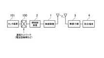
図1は自動通報無線通信システムの概略構成図である。図1に示すように、自動通報無線通信システムは、無線親機1、網制御装置2、無線子機3、防災端末4を備えて構成され、無線親機1は網制御装置2及び通信ネットワーク100を介してセンタ装置101等の上位機器に接続され、無線子機3は火災感知器等の防災端末4に接続されている。本発明の無線通信装置は、図1の無線親機1または無線子機3である。 FIG. 1 is a schematic configuration diagram of an automatic notification wireless communication system. As shown in FIG. 1, the automatic notification wireless communication system includes a wireless master device 1, a
この自動通報無線通信システムは、防災端末4で異常が検知された場合に、無線子機3から無線親機1へ異常情報を無線送信し、通信ネットワーク100を介してセンタ装置101に通報する。また、無線親機1及び無線子機3を新規に設置する場合、無線親機1と無線子機3間で電波が十分とどいているかどうかを確認するためのテスト通信を行う。 When an abnormality is detected in the
このテスト通信は、次のような手順で行われる。まず、テスト通信を開始するためのテスト起動信号を無線親機1から無線子機3へ無線送信する。次に、無線子機3はテスト起動信号に応答して、テスト信号を無線親機1へ無線送信する。無線親機1は、受信したテスト信号の電界強度が予め設定されたしきい値よりも大きいかどうかによって無線子機3と無線親機1間の電波状況を確認する。なお、テスト通信は、無線子機3から無線親機1へテスト起動信号を無線送信し、これに応答して無線親機1から無線子機3へテスト信号を無線送信するものとしてもよい。 This test communication is performed in the following procedure. First, a test activation signal for starting test communication is wirelessly transmitted from the wireless master device 1 to the
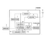
図2は本発明の実施例1に係る無線親機1の機能構成を示すブロック図である。図2に示すように、無線親機1は、アンテナ5、受信回路部6、電界強度測定部7、送信回路部8、信号処理部9、電源回路部12、テスト通信起動部14及び報知部15を備えて構成されている。また、信号処理部9は、電文解析部10、制御回路部11及びしきい値設定部13を備えている。 FIG. 2 is a block diagram illustrating a functional configuration of the wireless master device 1 according to the first embodiment of the invention. As shown in FIG. 2, the wireless master device 1 includes an
受信回路部6は、アンテナ5を介して信号を無線受信する。送信回路部8は、アンテナ5を介して信号を無線送信する。電源回路部12は、信号処理部9に電源を供給する。 The
電界強度測定部7は、受信回路部6で受信した信号の電界強度を測定して測定値を制御回路部11に出力する。電文解析部10は、受信回路部6で受信した信号を制御回路部11に出力するとともに受信した信号の電文を解析して、テスト起動信号およびテスト信号であるかどうかを判断する。 The electric field
制御回路部11は、受信した信号がテスト起動信号およびテスト信号でない場合、信号を網制御装置2に出力する。制御回路部11は、受信した信号がテスト起動信号である場合、無線子機3に対してテスト信号を無線送信する。制御回路部11は、受信した信号がテスト信号である場合、電界強度測定部7から出力された電界強度の測定値と、しきい値設定部13に予め設定されたしきい値とを比較して、電界強度の測定値がしきい値よりも大きい場合は、信号を網制御装置2に出力する。電界強度の測定値がしきい値よりも小さい場合は、報知部15にエラー報知するとともにエラー報知電文を網制御装置2に出力して、通信を終了する。このとき、エラー報知電文を出力する替わりに網制御装置2に信号を出力せずに無応答状態として通信を終了してもよい。 The
しきい値設定部13は、テスト通信時に受信回路部6で受信した信号の電界強度と比較されるしきい値が予め設定されている。このしきい値は、設置後の家具の配置変更による電波状況の変化や、昼夜での電波状況の変化や、フェージング等を考慮して設定される。 The threshold
テスト通信起動部14は、無線親機1から無線子機3へテスト起動信号無線送信し、無線子機3から無線親機1へテスト信号を無線送信してテスト通信を行う場合に、テスト起動信号を制御回路部11に発生させるテスト起動信号発生手段である。テスト起動信号は、制御回路部11から送信回路部8に出力され、送信回路部8は、アンテナ5を介して、無線子機3に無線送信する。 The test
図3は本発明の実施例1に係る無線子機3の機能構成を示すブロック図である。図3に示すように、無線子機3は、アンテナ16、受信回路部17、電界強度測定部18、送信回路部19、信号処理部20、電源回路部23、テスト通信起動部26及び報知部25を備えて構成されている。また、信号処理部20は、電文解析部21、制御回路部22及びしきい値設定部24を備えている。 FIG. 3 is a block diagram showing a functional configuration of the
受信回路部17は、アンテナ16を介して信号を無線受信する。送信回路部19は、アンテナ16を介して信号を無線送信する。電源回路部23は、信号処理部20に電源を供給する。 The
電界強度測定部18は、受信回路部17で受信した信号の電界強度を測定して測定値を制御回路部22に出力する。電文解析部21は、受信回路部17で受信した信号を制御回路部22に出力するとともに受信した信号の電文を解析して、テスト起動信号およびテスト信号であるかどうかを判断する。 The electric field
制御回路部22は、受信した信号がテスト起動信号およびテスト信号でない場合、通常の通信を行う。制御回路部22は、受信した信号がテスト起動信号である場合、無線親機1に対してテスト信号を無線送信する。制御回路部22は、受信した信号がテスト信号である場合、電界強度測定部18から出力された電界強度の測定値と、しきい値設定部24に予め設定されたしきい値とを比較して、電界強度の測定値がしきい値よりも大きい場合は、通常の通信を行う。電界強度の測定値がしきい値よりも小さい場合は、報知部25にエラー報知して、通信を終了する。 The
テスト通信起動部26は、無線子機3から無線親機1へテスト起動信号無線送信し、無線親機1から無線子機3へテスト信号を無線送信してテスト通信を行う場合に、テスト起動信号を制御回路部22に発生させるテスト起動信号発生手段である。テスト起動信号は、制御回路部22から送信回路部19に出力される。送信回路部19は、テスト起動信号をアンテナ16を介して、無線親機1に無線送信する。 The test communication activation unit 26 transmits a test activation signal wirelessly from the
なお、無線子機3から無線親機1へテスト起動信号を無線送信して、テスト通信を行う場合、無線親機1の電界強度測定部7、しきい値設定部13、テスト通信起動部14、報知部15は省略可能である。また、テスト起動信号は防災端末4から出力され、制御回路部22に入力されるものとしてもよい。 In addition, when performing a test communication by wirelessly transmitting a test activation signal from the
また、無線親機1から無線子機3へテスト起動信号を無線送信して、テスト通信を行う場合、無線子機3の電界強度測定部18、しきい値設定部24、テスト通信起動部26、報知部25は省略可能である。また、テスト起動信号はセンタ装置101から出力され、通信ネットワーク100及び網制御装置2を介して制御回路部11に入力されるものとしてもよい。 Also, when performing a test communication by wirelessly transmitting a test activation signal from the wireless master device 1 to the
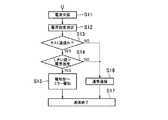
次に、本発明の実施例1に係る無線通信装置の動作を詳細に説明する。まず、無線子機3からの信号を無線親機1が無線受信する際の動作を図4に示すフローチャートを用いて説明する。無線親機1の受信回路部6は、アンテナ5を介して信号を無線受信する(ステップS1)。電界強度測定部7は、受信した信号の電界強度を測定して、測定値を制御回路部11に出力する(ステップS2)。電文解析部10は、受信した信号の電文を解析して、テスト信号であるかどうかを判断する(ステップS3)。受信した信号がテスト信号であった場合、制御回路部11は、電界強度の測定値と、しきい値設定部13に設定されたしきい値とを比較する(ステップS4)。電界強度の測定値がしきい値よりも小さいとき報知部15にエラー報知するとともにエラー報知電文を網制御装置2に出力して(ステップS5)、通信を終了する(ステップS7)。ステップS3で、受信した信号がテスト信号でない場合またはステップS4で、電界強度の測定値がしきい値よりも大きい場合、制御回路部11は、信号を網制御装置2に出力して通常の通信を行い(ステップS6)、通信を終了する(ステップS7)。 Next, the operation of the wireless communication apparatus according to the first embodiment of the present invention will be described in detail. First, the operation when the wireless master device 1 wirelessly receives a signal from the
次に、無線親機1からの信号を無線子機3が無線受信する際の動作を図5に示すフローチャートを用いて説明する。無線子機3の受信回路部17は、アンテナ16を介して信号を無線受信する(ステップS11)。電界強度測定部18は、受信した信号の電界強度を測定して、測定値を制御回路部22に出力する(ステップS12)。電文解析部21は、受信した信号の電文を解析して、テスト信号であるかどうかを判断する(ステップS13)。受信した信号がテスト信号であった場合、制御回路部22は、電界強度の測定値と、しきい値設定部24に設定されたしきい値とを比較する(ステップS14)。電界強度の測定値がしきい値よりも小さいとき報知部25にエラー報知して(ステップS15)、通信を終了する(ステップS17)。ステップS13で、受信した信号がテスト信号でない場合またはステップS14で、電界強度の測定値がしきい値よりも大きい場合、制御回路部22は、通常の通信を行い(ステップS16)、通信を終了する(ステップS17)。 Next, the operation when the
このように、本発明の実施例1に係る無線通信装置及び無線通信システムは、無線受信した信号がテスト信号であると判断されたときに、電界強度測定部で測定された電界強度と、しきい値設定部に設定されたしきい値とを制御回路部が比較する。電界強度の測定値がしきい値よりも大きいときは通常の通信を行い、測定値がしきい値よりも小さいときはエラー報知するので、無線子機3及び無線親機1を新規に設置する場合、設置後の電波状況を考慮したテスト通信を容易に行うことができる。このため、設置後の家具の配置変更による電波状況の変化や、昼夜での電波状況の変化や、フェージング等が発生した場合でもより高い通信品質の確保ができる。 As described above, the wireless communication device and the wireless communication system according to the first embodiment of the present invention use the electric field strength measured by the electric field strength measuring unit when the wirelessly received signal is determined to be a test signal. The control circuit unit compares the threshold value set in the threshold value setting unit. When the measured value of the electric field strength is larger than the threshold value, normal communication is performed, and when the measured value is smaller than the threshold value, an error is notified, so the
また、電界強度測定部を無線親機1または無線子機3の中に設けたので、電界強度を正確に行うことができる。 Moreover, since the electric field strength measuring unit is provided in the wireless master device 1 or the
図6は本発明の実施例2に係る無線親機1aの機能構成を示すブロック図である。図6に示すように、無線親機1aは、図2に示す実施例1の無線親機1に設けられていた電界強度測定部7、しきい値設定部13をなくし、信号減衰部27及びスイッチSW1を追加したものである。その他の構成は実施例1の無線親機1と同様であり、同様の構成には同様の符号を付し、詳細は省略する。 FIG. 6 is a block diagram showing a functional configuration of the wireless master device 1a according to the second embodiment of the present invention. As shown in FIG. 6, the wireless master device 1a eliminates the electric field
スイッチSW1は、共通端子30に接片31の一端が接続され、接片31の他端が選択端子28または選択端子29に切り替え接続される。共通端子30には送信回路部8が接続され、選択端子28にはアンテナ5が接続され、選択端子29には信号減衰部27の一端が接続され、信号減衰部27の他端にはアンテナ5が接続されている。スイッチSW1は通常の通信を行う場合、接片31は選択端子28に接続されている。 In the switch SW1, one end of the
信号減衰部27は、無線親機1aから無線子機3a(後述)へテスト起動信号を無線送信する場合に、テスト起動信号の送信電力を減衰させてアンテナ5へ出力するものであり、減衰量はフェージング等による電波状況の変化を考慮して設定される。 The
制御回路部11は、テスト通信起動部14からの指示によりテスト通信を行う場合、スイッチSW1の接片31を選択端子29側に切り替えて、テスト起動信号を送信回路部8及び信号減衰部27を介してアンテナ5に出力する。また、制御回路部11は、無線子機3aからのテスト信号を正常に受信できない場合は、報知部15にエラー報知するとともに網制御装置2にエラー報知電文を出力して、通信を終了する。このとき、エラー報知電文を出力する替わりに網制御装置2に信号を出力せずに無応答状態として通信を終了してもよい。 When performing the test communication according to the instruction from the test
図7は本発明の実施例2に係る無線子機3aの機能構成を示すブロック図である。図7に示すように、無線子機3aは、図3に示す実施例1の無線子機3に設けられていた電界強度測定部18、しきい値設定部24をなくし、信号減衰部32及びスイッチSW2を追加したものである。その他の構成は実施例1の無線子機3と同様であり、同様の構成には同様の符号を付し、詳細は省略する。 FIG. 7 is a block diagram showing a functional configuration of the wireless slave device 3a according to the second embodiment of the present invention. As shown in FIG. 7, the wireless slave device 3a eliminates the electric field
スイッチSW2は、共通端子38に接片40の一端が接続され、接片40の他端が選択端子39または選択端子37に切り替え接続される。共通端子38には送信回路部19が接続され、選択端子39にはアンテナ16が接続され、選択端子37には信号減衰部32の一端が接続され、信号減衰部32の他端にはアンテナ16が接続されている。スイッチSW2は通常の通信を行う場合、接片40は選択端子39に接続されている。 In the switch SW2, one end of the
信号減衰部32は、無線子機3aから無線親機1aへテスト起動信号を無線送信する場合に、テスト起動信号の送信電力を減衰させてアンテナ16へ出力するものであり、減衰量はフェージング等による電波状況の変化を考慮して設定される。 The
制御回路部22は、テスト通信起動部26からの指示によりテスト通信を行う場合、スイッチSW2の接片40を選択端子37側に切り替えて、テスト起動信号を送信回路部19及び信号減衰部32を介してアンテナ16に出力する。また、制御回路部22は、無線親機1aからのテスト信号を正常に受信できない場合は、報知部25にエラー報知して、通信を終了する。 When performing the test communication according to the instruction from the test communication activation unit 26, the
なお、無線子機3aから無線親機1aへテスト起動信号を無線送信して、テスト通信を行う場合、無線親機1aのテスト通信起動部14、報知部15、信号減衰部27は省略可能である。 Note that when performing a test communication by wirelessly transmitting a test activation signal from the wireless slave device 3a to the wireless master device 1a, the test
また、無線親機1aから無線子機3aへテスト起動信号を無線送信して、テスト通信を行う場合、無線子機3aのテスト通信起動部26、報知部25、信号減衰部32は省略可能である。 Further, when performing a test communication by wirelessly transmitting a test activation signal from the wireless master device 1a to the wireless slave device 3a, the test communication activation unit 26, the
このように、本発明の実施例2に係る無線通信装置及び無線通信システムは、テスト通信を行う際は、テスト起動信号の送信電力を信号減衰部により減衰させて送信するので、無線子機3a及び無線親機1aを新規に設置する場合、設置後の電波状況を考慮したテスト通信を容易に行うことができる。このため、設置後の家具の配置変更による電波状況の変化や、昼夜での電波状況の変化や、フェージング等が発生した場合でもより高い通信品質の確保ができる。 As described above, when performing the test communication, the wireless communication device and the wireless communication system according to the second embodiment of the present invention attenuate the transmission power of the test activation signal by the signal attenuating unit and transmit the wireless slave device 3a. And when the radio | wireless main | base station 1a is newly installed, the test communication which considered the radio wave condition after installation can be performed easily. For this reason, higher communication quality can be ensured even when a change in the radio wave condition due to a change in the arrangement of furniture after installation, a change in the radio wave condition during the day or night, fading, or the like occurs.
図8は本発明の実施例3に係る無線親機1bの機能構成を示すブロック図である。図8に示すように、無線親機1bは、図6に示す実施例2の無線親機1aの受信回路部6と送信回路部8とを入れ替えて、スイッチSW1の替わりにSW3を設けたものである。その他の構成は実施例2の無線親機1aと同様であり、同様の構成には同様の符号を付し、詳細は省略する。 FIG. 8 is a block diagram showing a functional configuration of the wireless master device 1b according to the third embodiment of the present invention. As shown in FIG. 8, the wireless master device 1b is obtained by replacing the receiving
スイッチSW3は、共通端子43に接片44の一端が接続され、接片44の他端が選択端子41または選択端子42に切り替え接続される。共通端子43には受信回路部6が接続され、選択端子41にはアンテナ5が接続され、選択端子42には信号減衰部27の一端が接続され、信号減衰部27の他端にはアンテナ5が接続されている。スイッチSW3は通常の通信を行う場合、接片44は選択端子41に接続されている。 In the switch SW3, one end of the
信号減衰部27は、無線子機3b(後述)から無線親機1bへテスト信号を無線送信する場合に、アンテナ5を介して受信したテスト信号の受信電力を減衰させて受信回路部6へ出力するものであり、減衰量はフェージング等による電波状況の変化を考慮して設定される。 The
制御回路部11は、テスト通信起動部14からの指示によりテスト通信を行う場合、スイッチSW3の接片44を選択端子42側に切り替える。テスト信号はアンテナ5、信号減衰部27及び受信回路部6、電文解析部10を介して制御回路部11に入力される。また、制御回路部11は、無線子機3bからの信号を正常に受信できない場合は、報知部15にエラー報知するとともにエラー報知電文を網制御装置2に出力して、通信を終了する。このとき、エラー報知電文を出力する替わりに網制御装置2に信号を出力せずに無応答状態として通信を終了してもよい。 The
図9は本発明の実施例3に係る無線子機3bの機能構成を示すブロック図である。図9に示すように、無線子機3bは、図7に示す実施例2の無線子機3aの受信回路部17と送信回路部19とを入れ替えて、スイッチSW2の替わりにSW4を設けたものである。その他の構成は実施例2の無線子機3aと同様であり、同様の構成には同様の符号を付し、詳細は省略する。 FIG. 9 is a block diagram illustrating a functional configuration of the wireless slave device 3b according to the third embodiment of the present invention. As shown in FIG. 9, the wireless slave device 3b is obtained by replacing the
スイッチSW4は、共通端子46に接片48の一端が接続され、接片48の他端が選択端子47または選択端子45に切り替え接続される。共通端子46には受信回路部17が接続され、選択端子47にはアンテナ16が接続され、選択端子45には信号減衰部32の一端が接続され、信号減衰部32の他端にはアンテナ16が接続されている。スイッチSW4は通常の通信を行う場合、接片48は選択端子47に接続されている。 In the switch SW4, one end of the
信号減衰部32は、無線親機1bから無線子機3bへテスト信号を無線送信する場合に、アンテナ16を介して受信したテスト信号の受信電力を減衰させて受信回路部17へ出力するものであり、減衰量はフェージング等による電波状況の変化を考慮して設定される。 The
制御回路部22は、テスト通信起動部26からの指示によりテスト通信を行う場合、スイッチSW4の接片48を選択端子45側に切り替える。テスト信号はアンテナ16、信号減衰部32及び受信回路部17および電文解析部21を介して制御回路部22に入力される。また、制御回路部22は、無線親機1bからの信号を正常に受信できない場合は、報知部25にエラー報知して、通信を終了する。 The
なお、無線子機3bから無線親機1bへテスト起動信号を無線送信して、テスト通信を行う場合、無線親機1bのテスト通信起動部14、信号減衰部27及び報知部15は省略可能である。 Note that when performing a test communication by wirelessly transmitting a test activation signal from the wireless slave device 3b to the wireless master device 1b, the test
また、無線親機1bから無線子機3bへテスト起動信号を無線送信して、テスト通信を行う場合、無線子機3bのテスト通信起動部26、信号減衰部32及び報知部25は省略可能である。 Further, when performing a test communication by wirelessly transmitting a test activation signal from the wireless master device 1b to the wireless slave device 3b, the test communication activation unit 26, the
このように、本発明の実施例3に係る無線通信装置及び無線通信システムは、テスト通信を行う際は、テスト信号の受信電力を信号減衰部により減衰させて受信するので、無線子機3b及び無線親機1bを新規に設置する場合、設置後の電波状況を考慮したテスト通信を容易に行うことができる。このため、設置後の家具の配置変更による電波状況の変化や、昼夜での電波状況の変化や、フェージング等が発生した場合でもより高い通信品質の確保ができる。 As described above, when performing the test communication, the wireless communication device and the wireless communication system according to the third embodiment of the present invention attenuate the received power of the test signal by the signal attenuating unit, and thus receive the wireless slave device 3b and When the wireless master device 1b is newly installed, test communication can be easily performed in consideration of the radio wave condition after the installation. For this reason, higher communication quality can be ensured even when a change in the radio wave condition due to a change in the arrangement of furniture after installation, a change in the radio wave condition during the day or night, fading, or the like occurs.
本発明は、新規に設置した場合に、運用時の電波状況を考慮したテスト通信を容易に行うことができる無線通信装置として利用可能である。 INDUSTRIAL APPLICABILITY The present invention can be used as a wireless communication apparatus that can easily perform test communication in consideration of radio wave conditions during operation when newly installed.
1 無線親機
2 網制御装置
3 無線子機
4 防災端末
5、16 アンテナ
7、18 電界強度測定部
8、19 送信回路部
9、20 信号処理部
10、21 電文解析部
11、22 制御回路部
12、23 電源回路部
13、24 しきい値設定部
14、26 テスト通信起動部
15、25 報知部
27、32 信号減衰部
100 通信ネットワーク
101 センタ装置DESCRIPTION OF SYMBOLS 1 Radio | wireless main |
Claims (5)
Translated fromJapanese前記無線信号の電界強度を測定する電界強度測定部と、
前記無線信号の電文を解析して、前記無線信号が、電波状況を確認するテスト通信であることを示すテスト信号であるかどうかを判断する電文解析部と、
前記無線信号が前記テスト信号であった場合に、前記電界強度測定部により測定された電界強度が予め設定されたしきい値よりも小さいかどうかを判定して、前記電界強度が前記しきい値よりも小さいときに、エラー報知を行う制御部と、
を備えることを特徴とする無線通信装置。A receiver for receiving a radio signal;
An electric field strength measuring unit for measuring the electric field strength of the radio signal;
A message analysis unit that analyzes the message of the wireless signal and determines whether the wireless signal is a test signal indicating test communication for checking a radio wave condition;
When the wireless signal is the test signal, it is determined whether the electric field strength measured by the electric field strength measuring unit is smaller than a preset threshold value, and the electric field strength is the threshold value. Control unit that performs error notification when smaller than,
A wireless communication apparatus comprising:
前記無線信号の送信電力を減衰させる信号減衰部と、
電波状況を確認するテスト通信を行う場合に、前記信号減衰部により前記無線信号の送信電力を減衰させる制御部と、
を備えることを特徴とする無線通信装置。A transmitter that transmits a radio signal;
A signal attenuator for attenuating the transmission power of the radio signal;
A control unit that attenuates the transmission power of the radio signal by the signal attenuating unit when performing test communication to confirm the radio wave condition;
A wireless communication apparatus comprising:
前記無線信号の受信電力を減衰させる信号減衰部と、
電波状況を確認するテスト通信を行う場合に、前記信号減衰部により前記無線信号の受信電力を減衰させる制御部と、
を備えることを特徴とする無線通信装置。A receiver for receiving a radio signal;
A signal attenuator for attenuating the received power of the radio signal;
A control unit that attenuates the received power of the radio signal by the signal attenuating unit when performing test communication for confirming radio wave conditions;
A wireless communication apparatus comprising:
前記無線子機は、
無線信号を受信する受信部と、
前記無線信号の電文を解析して、前記無線信号が電波状況を確認するテスト通信を開始するためのテスト起動信号であるかどうかを判断する電文解析部と、
前記無線信号が前記テスト起動信号であった場合に、前記テスト通信であることを示すテスト信号を送信する送信部と、
を備え、
前記無線親機は、
前記無線信号を送信する送信部と、
前記テスト通信を行う場合に、前記テスト起動信号を発生させて前記送信部に出力するテスト起動信号発生手段と、
前記無線信号を受信する受信部と、
前記無線信号の電文を解析して、前記無線信号が前記テスト信号であるかどうかを判断する電文解析部と、
前記無線信号が前記テスト信号であった場合に、前記電界強度測定部により測定された電界強度が予め設定されたしきい値よりも小さいかどうかを判定して、前記電界強度が前記しきい値よりも小さいときに、エラー報知を行う制御部と、
を備えることを特徴とする無線通信システム。It consists of a wireless master unit and a wireless slave unit,
The wireless slave is
A receiver for receiving a radio signal;
Analyzing the telegram of the radio signal, a telegram analyzer for determining whether the radio signal is a test activation signal for starting test communication for confirming radio wave conditions;
A transmitter that transmits a test signal indicating the test communication when the wireless signal is the test activation signal;
With
The wireless master unit is
A transmitter for transmitting the wireless signal;
When performing the test communication, a test activation signal generating means for generating the test activation signal and outputting it to the transmission unit;
A receiver for receiving the radio signal;
A message analysis unit that analyzes the message of the wireless signal and determines whether the wireless signal is the test signal;
When the radio signal is the test signal, it is determined whether the electric field strength measured by the electric field strength measurement unit is smaller than a preset threshold value, and the electric field strength is the threshold value Control unit that performs error notification when smaller than,
A wireless communication system comprising:
前記無線親機は、
無線信号を受信する受信部と、
前記無線信号の電文を解析して、前記無線信号が電波状況を確認するテスト通信を開始するためのテスト起動信号であるかどうかを判断する電文解析部と、
前記無線信号が前記テスト起動信号であった場合に、前記テスト通信であることを示すテスト信号を送信する送信部と、
を備え、
前記無線子機は、
前記無線信号を送信する送信部と、
前記テスト通信を行う場合に、前記テスト起動信号を発生させて前記送信部に出力するテスト起動信号発生手段と、
前記無線信号を受信する受信部と、
前記無線信号の電文を解析して、前記無線信号が前記テスト信号であるかどうかを判断する電文解析部と、
前記無線信号が前記テスト信号であった場合に、前記電界強度測定部により測定された電界強度が予め設定されたしきい値よりも小さいかどうかを判定して、前記電界強度が前記しきい値よりも小さいときに、エラー報知を行う制御部と、
を備えることを特徴とする無線通信システム。It consists of a wireless master unit and a wireless slave unit,
The wireless master unit is
A receiver for receiving a radio signal;
Analyzing the telegram of the radio signal, a telegram analyzer for determining whether the radio signal is a test activation signal for starting test communication for confirming radio wave conditions;
A transmitter that transmits a test signal indicating the test communication when the wireless signal is the test activation signal;
With
The wireless slave is
A transmitter for transmitting the wireless signal;
When performing the test communication, a test activation signal generating means for generating the test activation signal and outputting it to the transmission unit;
A receiver for receiving the radio signal;
A message analysis unit that analyzes the message of the wireless signal and determines whether the wireless signal is the test signal;
When the radio signal is the test signal, it is determined whether the electric field strength measured by the electric field strength measurement unit is smaller than a preset threshold value, and the electric field strength is the threshold value Control unit that performs error notification when smaller than,
A wireless communication system comprising:
Priority Applications (1)
| Application Number | Priority Date | Filing Date | Title |
|---|---|---|---|
| JP2005154046AJP2006333090A (en) | 2005-05-26 | 2005-05-26 | Wireless communication apparatus and wireless communication system |
Applications Claiming Priority (1)
| Application Number | Priority Date | Filing Date | Title |
|---|---|---|---|
| JP2005154046AJP2006333090A (en) | 2005-05-26 | 2005-05-26 | Wireless communication apparatus and wireless communication system |
Publications (1)
| Publication Number | Publication Date |
|---|---|
| JP2006333090Atrue JP2006333090A (en) | 2006-12-07 |
Family
ID=37554302
Family Applications (1)
| Application Number | Title | Priority Date | Filing Date |
|---|---|---|---|
| JP2005154046APendingJP2006333090A (en) | 2005-05-26 | 2005-05-26 | Wireless communication apparatus and wireless communication system |
Country Status (1)
| Country | Link |
|---|---|
| JP (1) | JP2006333090A (en) |
Cited By (9)
| Publication number | Priority date | Publication date | Assignee | Title |
|---|---|---|---|---|
| JP2009217592A (en)* | 2008-03-11 | 2009-09-24 | Panasonic Electric Works Co Ltd | Radio system |
| JP2010027085A (en)* | 2009-11-02 | 2010-02-04 | Panasonic Electric Works Co Ltd | Fire alarm system |
| JP2010134739A (en)* | 2008-12-05 | 2010-06-17 | Nohmi Bosai Ltd | Alarm device |
| JP2010223536A (en)* | 2009-03-25 | 2010-10-07 | Panasonic Corp | Wireless system, wireless system communication control method, and program |
| JP2013176033A (en)* | 2012-01-23 | 2013-09-05 | Panasonic Corp | Radio communication system |
| JP2013200860A (en)* | 2012-02-22 | 2013-10-03 | Panasonic Corp | Radio communication system |
| JP2014056419A (en)* | 2012-09-12 | 2014-03-27 | Panasonic Corp | Wireless communication system |
| JP2023131533A (en)* | 2022-03-09 | 2023-09-22 | アンリツ株式会社 | Local 5g monitoring system and abnormal state detection method thereof |
| JP2023131534A (en)* | 2022-03-09 | 2023-09-22 | アンリツ株式会社 | Local 5g monitoring system and measurement data providing method thereof |
Citations (10)
| Publication number | Priority date | Publication date | Assignee | Title |
|---|---|---|---|---|
| JPS58186239A (en)* | 1982-04-24 | 1983-10-31 | Nippon Telegr & Teleph Corp <Ntt> | Channel switching test system of mobile communication |
| JPH0669849A (en)* | 1992-08-19 | 1994-03-11 | Hitachi Ltd | Mobile object communication system provided with testing function and testing method |
| JPH08102721A (en)* | 1994-09-29 | 1996-04-16 | Tokyo Gas Co Ltd | Wireless communication system |
| JPH1022945A (en)* | 1996-07-05 | 1998-01-23 | Matsushita Electric Ind Co Ltd | Telemeter and telecontrol device |
| JP2000138601A (en)* | 1998-10-30 | 2000-05-16 | Nec Corp | Antenna and transmitter-receiver |
| JP2000244422A (en)* | 1999-02-18 | 2000-09-08 | Yaesu Musen Co Ltd | System for confirming transmission performance |
| JP2001044925A (en)* | 1999-08-04 | 2001-02-16 | Zojirushi Corp | Radio monitoring system |
| JP2003030773A (en)* | 2001-07-18 | 2003-01-31 | Matsushita Electric Ind Co Ltd | Wireless data collection system |
| JP2003217066A (en)* | 2002-01-23 | 2003-07-31 | Matsushita Electric Ind Co Ltd | Automatic meter reading wireless measurement device |
| JP2004282587A (en)* | 2003-03-18 | 2004-10-07 | Matsushita Electric Ind Co Ltd | Wireless data collection system |
- 2005
- 2005-05-26JPJP2005154046Apatent/JP2006333090A/enactivePending
Patent Citations (10)
| Publication number | Priority date | Publication date | Assignee | Title |
|---|---|---|---|---|
| JPS58186239A (en)* | 1982-04-24 | 1983-10-31 | Nippon Telegr & Teleph Corp <Ntt> | Channel switching test system of mobile communication |
| JPH0669849A (en)* | 1992-08-19 | 1994-03-11 | Hitachi Ltd | Mobile object communication system provided with testing function and testing method |
| JPH08102721A (en)* | 1994-09-29 | 1996-04-16 | Tokyo Gas Co Ltd | Wireless communication system |
| JPH1022945A (en)* | 1996-07-05 | 1998-01-23 | Matsushita Electric Ind Co Ltd | Telemeter and telecontrol device |
| JP2000138601A (en)* | 1998-10-30 | 2000-05-16 | Nec Corp | Antenna and transmitter-receiver |
| JP2000244422A (en)* | 1999-02-18 | 2000-09-08 | Yaesu Musen Co Ltd | System for confirming transmission performance |
| JP2001044925A (en)* | 1999-08-04 | 2001-02-16 | Zojirushi Corp | Radio monitoring system |
| JP2003030773A (en)* | 2001-07-18 | 2003-01-31 | Matsushita Electric Ind Co Ltd | Wireless data collection system |
| JP2003217066A (en)* | 2002-01-23 | 2003-07-31 | Matsushita Electric Ind Co Ltd | Automatic meter reading wireless measurement device |
| JP2004282587A (en)* | 2003-03-18 | 2004-10-07 | Matsushita Electric Ind Co Ltd | Wireless data collection system |
Cited By (9)
| Publication number | Priority date | Publication date | Assignee | Title |
|---|---|---|---|---|
| JP2009217592A (en)* | 2008-03-11 | 2009-09-24 | Panasonic Electric Works Co Ltd | Radio system |
| JP2010134739A (en)* | 2008-12-05 | 2010-06-17 | Nohmi Bosai Ltd | Alarm device |
| JP2010223536A (en)* | 2009-03-25 | 2010-10-07 | Panasonic Corp | Wireless system, wireless system communication control method, and program |
| JP2010027085A (en)* | 2009-11-02 | 2010-02-04 | Panasonic Electric Works Co Ltd | Fire alarm system |
| JP2013176033A (en)* | 2012-01-23 | 2013-09-05 | Panasonic Corp | Radio communication system |
| JP2013200860A (en)* | 2012-02-22 | 2013-10-03 | Panasonic Corp | Radio communication system |
| JP2014056419A (en)* | 2012-09-12 | 2014-03-27 | Panasonic Corp | Wireless communication system |
| JP2023131533A (en)* | 2022-03-09 | 2023-09-22 | アンリツ株式会社 | Local 5g monitoring system and abnormal state detection method thereof |
| JP2023131534A (en)* | 2022-03-09 | 2023-09-22 | アンリツ株式会社 | Local 5g monitoring system and measurement data providing method thereof |
Similar Documents
| Publication | Publication Date | Title |
|---|---|---|
| US8396007B2 (en) | Wireless device deployment with reliable links | |
| KR101013261B1 (en) | Mobile communication system, mobile station, base transceiver station and method of using the same | |
| JP4732963B2 (en) | Wireless base station test equipment | |
| JP2006333090A (en) | Wireless communication apparatus and wireless communication system | |
| JPH10107744A (en) | Self-dignostic method for radio communication equipment and device therefor | |
| JP2002094449A (en) | Wireless access system | |
| JP2001169338A (en) | Base station device and wireless access system | |
| JP5527788B2 (en) | COMMUNICATION TERMINAL DEVICE MOUNTING MULTIPLE RADIO DEVICE, RADIO CIRCUIT DIAGNOSIS METHOD IN THE SAME, AND PROGRAM FOR THE METHOD | |
| KR100367079B1 (en) | System and method for detecting errors of mobile communication repeater | |
| JP2006339762A (en) | Wireless terminal | |
| JP2007300234A (en) | Relay monitoring device | |
| JP2007274273A (en) | Wireless communication system | |
| JP6163470B2 (en) | Wireless communication device communication status confirmation device | |
| KR101688962B1 (en) | Device and method of PS-LTE mobile battery management | |
| JP2859135B2 (en) | Wireless security system | |
| JP2020123890A (en) | Communication device, system, method and program | |
| JP2007104648A (en) | Radio communication system, base station, exchange, and cell interference area detecting method used for the same | |
| JP2002232337A (en) | Wireless communication method and system | |
| JP2005346533A (en) | Wireless security system | |
| KR19990038305A (en) | Transmission and reception equipment inspection device and inspection method of base station | |
| JP2001230737A (en) | Wireless device failure diagnosis method | |
| JP2022085789A (en) | Communication equipment, communication systems, and communication methods | |
| JP2014158147A (en) | Radio terminal device, and method for diagnosing abnormality of transmitter | |
| KR19990040536A (en) | Method and apparatus for state management of test terminal in base station system | |
| JP2005236820A (en) | Notification method when emergency power supply is in use |
Legal Events
| Date | Code | Title | Description |
|---|---|---|---|
| A621 | Written request for application examination | Free format text:JAPANESE INTERMEDIATE CODE: A621 Effective date:20080311 | |
| A711 | Notification of change in applicant | Free format text:JAPANESE INTERMEDIATE CODE: A712 Effective date:20100303 | |
| A977 | Report on retrieval | Free format text:JAPANESE INTERMEDIATE CODE: A971007 Effective date:20101025 | |
| A131 | Notification of reasons for refusal | Free format text:JAPANESE INTERMEDIATE CODE: A131 Effective date:20101102 | |
| A02 | Decision of refusal | Free format text:JAPANESE INTERMEDIATE CODE: A02 Effective date:20110426 |