JP2006333058A - Bone conduction mobile phone - Google Patents
Bone conduction mobile phoneDownload PDFInfo
- Publication number
- JP2006333058A JP2006333058AJP2005153703AJP2005153703AJP2006333058AJP 2006333058 AJP2006333058 AJP 2006333058AJP 2005153703 AJP2005153703 AJP 2005153703AJP 2005153703 AJP2005153703 AJP 2005153703AJP 2006333058 AJP2006333058 AJP 2006333058A
- Authority
- JP
- Japan
- Prior art keywords
- mobile phone
- bone conduction
- user
- bone
- main body
- Prior art date
- Legal status (The legal status is an assumption and is not a legal conclusion. Google has not performed a legal analysis and makes no representation as to the accuracy of the status listed.)
- Pending
Links
- 210000000988bone and boneAnatomy0.000titleclaimsabstractdescription77
- 210000000707wristAnatomy0.000claimsabstractdescription27
- 210000000245forearmAnatomy0.000claimsdescription8
- 125000002066L-histidyl groupChemical group[H]N1C([H])=NC(C([H])([H])[C@](C(=O)[*])([H])N([H])[H])=C1[H]0.000description8
- 210000003811fingerAnatomy0.000description8
- 210000003625skullAnatomy0.000description8
- 210000000216zygomaAnatomy0.000description4
- 210000003813thumbAnatomy0.000description3
- 210000003027ear innerAnatomy0.000description1
- 210000002411hand boneAnatomy0.000description1
- 239000004973liquid crystal related substanceSubstances0.000description1
Images


Landscapes
- Details Of Audible-Bandwidth Transducers (AREA)
- Telephone Set Structure (AREA)
- Telephone Function (AREA)
Abstract
Description
Translated fromJapanese本発明は、骨伝導振動体を用いた携帯電話に関する。 The present invention relates to a mobile phone using a bone conduction vibrator.
近年、骨伝導振動体(骨伝導スピーカ)を用いた携帯電話が製造されるようになってきている。このような骨伝導式携帯電話を使用する場合、使用者は、骨伝導スピーカを自らの頭蓋骨(例えば頬骨)に接触させることにより、骨伝導スピーカからの骨導音を取得する。これにより、使用者は、周囲に騒音がある場合でも、携帯電話からクリアな音声を取得することができる。 In recent years, mobile phones using bone conduction vibrators (bone conduction speakers) have been manufactured. When using such a bone conduction type mobile phone, the user obtains bone conduction sound from the bone conduction speaker by bringing the bone conduction speaker into contact with his / her skull (for example, cheekbone). Thereby, the user can acquire a clear voice from the mobile phone even when there is noise in the surroundings.
一方、本出願人は、国際公開WO99/59314(特願2000−549014号、PCT/JP98/05899)において、腕取り付け型携帯電話を提案している。この腕取り付け型携帯電話は、腕時計のように使用者の手首に装着して使用できるもので、携帯電話の利便性を高めたものである。 On the other hand, the present applicant has proposed an arm-mounted mobile phone in International Publication WO99 / 59314 (Japanese Patent Application No. 2000-549014, PCT / JP98 / 05899). This arm-attached mobile phone can be used by being worn on the wrist of a user like a wristwatch, and improves the convenience of the mobile phone.
しかしながら、従来の骨伝導式携帯電話は、使用時に骨伝導スピーカを頭蓋骨に接触させる必要があり、必ずしも使い勝手がよいとは言えない。また、骨伝導スピーカを耳に装着する形態も考えられるが、骨伝導スピーカを耳に装着しておくのは煩わしい。 However, the conventional bone conduction type mobile phone needs to bring the bone conduction speaker into contact with the skull at the time of use, and is not necessarily easy to use. Although a form in which the bone conduction speaker is attached to the ear is also conceivable, it is troublesome to attach the bone conduction speaker to the ear.
また、骨伝導式携帯電話を腕取り付け型にした場合、使用者は、骨伝導スピーカを頭蓋骨に接触させるために不自然な姿勢をとらねばならない。また、骨伝導スピーカを頭蓋骨に接触させた状態では、携帯電話の音声取得用のマイクを使用者の口元に配置することは難しい。 In addition, when the bone conduction type mobile phone is an arm-mounted type, the user must take an unnatural posture in order to bring the bone conduction speaker into contact with the skull. In addition, in a state where the bone conduction speaker is in contact with the skull, it is difficult to place a microphone for acquiring voice of a mobile phone at the user's mouth.
本発明は、このような問題点に着目してなされたもので、腕取り付け型として使用でき、利便性及び使用の容易性を著しく高め得る骨伝導式携帯電話を提供することを目的とする。 The present invention has been made paying attention to such problems, and an object of the present invention is to provide a bone conduction type mobile phone that can be used as an arm-mounted type and can remarkably improve convenience and ease of use.
本発明は、骨伝導式携帯電話において、携帯電話本体と、使用者の前腕及び手の少なくとも一部に接触した状態で設置可能な振動体と、前記携帯電話本体からの信号に基づいて前記振動体を振動させる手段とを備えた。 The present invention relates to a bone-conduction type mobile phone, a mobile phone body, a vibrator that can be installed in contact with at least a part of a user's forearm and hand, and the vibration based on a signal from the mobile phone body. Means for vibrating the body.
前記携帯電話本体は、本体部と、前記本体部を使用者の手首に固定するバンド部とを備え、前記振動体は、前記本体部の裏面に取り付けられているようにしてもよい。
前記本体部は、使用者が前記骨伝導式携帯電話を装着したときに、使用者の手の甲側の手首付近に配置されるようにしてもよい。The mobile phone main body may include a main body portion and a band portion that fixes the main body portion to a user's wrist, and the vibrator may be attached to the back surface of the main body portion.
The main body may be arranged near the wrist on the back side of the user's hand when the user wears the bone conduction mobile phone.
音声取得手段を更に備え、前記音声取得手段は、使用者が前記骨伝導式携帯電話を装着したときに、使用者の手の平側の手首付近に配置されるようにしてもよい。
前記バンド部にバッテリーを内蔵してもよい。Voice acquisition means may further be provided, and the voice acquisition means may be arranged near the wrist on the palm side of the user's palm when the user wears the bone conduction mobile phone.
A battery may be built in the band part.
前記本体部は、表示部を有する主部と、前記主部の両側に隣接して配置された操作部とからなるようにしてもよい。
前記主部の両側の操作部のそれぞれに、略同数の操作用ボタンを配置するようにしてもよい。The main body may be composed of a main part having a display part and an operation part arranged adjacent to both sides of the main part.
You may make it arrange | position substantially the same number of operation buttons in each of the operation part of the both sides of the said main part.
前記振動体を振動させる手段は、携帯電話への着信時に前記振動体を振動させ得るようにしてもよい。
使用者の指に装着可能なリング部を備え、前記振動体は、前記リング部に取り付けられるようにしてもよい。The means for vibrating the vibrating body may be configured to vibrate the vibrating body when receiving an incoming call to a mobile phone.
A ring portion that can be attached to a user's finger may be provided, and the vibrator may be attached to the ring portion.
本発明によれば、振動体(例えば、骨伝導スピーカ10、21)は、使用者の前腕及び手の少なくとも一部に接触して配置されるので、使用者は、自らの手を耳に被せて配置することにより、振動体から伝達された骨伝導によって振動する手をスピーカのように用いて、手から発せられる音を聞くことができる。また、別法として、使用者は、自らの手を頭蓋骨に接触させる(例えば、耳付近に当てて配置する、又は頬骨に当てて配置する)ことにより、振動体からの骨導音を、使用者の前腕及び手を介して取得することができる。したがって、携帯電話からの音声情報取得のための動作が容易となり、骨伝導式携帯電話の使用が容易となる。 According to the present invention, since the vibrating body (for example, the
また、携帯電話本体に、本体部(例えば、本体部2)とバンド部(例えば、バンド部3)を備え、振動体(例えば、骨伝導スピーカ10)を本体部の裏面(例えば、主部4の裏面4B)に配置すれば、骨伝導式携帯電話を腕取り付け型の携帯電話(例えば、腕取り付け型携帯電話1)として構成できる。これにより、骨伝導式携帯電話の利便性が更に高められる。 Further, the mobile phone main body includes a main body (for example, the main body 2) and a band (for example, the band 3), and the vibrating body (for example, the bone conduction speaker 10) is attached to the back surface (for example, the main 4). If it is arranged on the
また、骨伝導式携帯電話を腕取り付け型とした場合、本体部が使用者の手の甲側の手首付近に配置されるようにすれば、振動体は、ちょうど使用者の手首部分の骨に接触して配置される。これにより、振動体からの骨伝導が、使用者の手首部分の骨に適切に伝達される。 In addition, when the bone conduction type mobile phone is an arm-mounted type, if the main body is arranged near the wrist on the back side of the user's hand, the vibrating body will contact the bone of the user's wrist. Arranged. Thereby, the bone conduction from a vibrating body is appropriately transmitted to the bone of a user's wrist part.
また、骨伝導式携帯電話を腕取り付け型とした場合、音声取得手段(例えば、マイク11)を、使用者の手の平側の手首付近に配置されるようにすれば、通話時に、使用者が手を耳に当てた姿勢をとると、音声取得手段がちょうど使用者の口元に配置されるようにできる。したがって、使用者は、楽な姿勢で通話をすることができる。 In addition, when the bone conduction type mobile phone is an arm-mounted type, if the voice acquisition means (for example, the microphone 11) is arranged near the wrist on the palm side of the user's hand, the user can The voice acquisition means can be arranged just at the user's mouth. Therefore, the user can make a call with an easy posture.
また、骨伝導式携帯電話を腕取り付け型とした場合、バンド部にバッテリーを内蔵すれば、本体部を小型化することができ、携帯電話を使用しやすいものとできる。
さらに、骨伝導式携帯電話を腕取り付け型とした場合、本体部に、主部(例えば、主部4)と、この主部の両側に隣接して配置された操作部(例えば、操作部5及び6)とを備えるようにすれば、使用者は、主部の表示部(例えば、表示画面7)を見ながら、操作部の操作ボタン(例えば、操作ボタン8)を親指と人差し指で操作することができる。したがって、携帯電話の操作性が高められる。Further, when the bone conduction type mobile phone is an arm-mounted type, if the battery is built in the band portion, the main body portion can be reduced in size and the mobile phone can be easily used.
Further, when the bone conduction type mobile phone is an arm-mounted type, a main part (for example, main part 4) and an operation part (for example, operation part 5) arranged adjacent to both sides of the main part are provided in the main body part. And 6), the user operates the operation button (for example, the operation button 8) of the operation unit with the thumb and the index finger while viewing the main display (for example, the display screen 7). be able to. Therefore, the operability of the mobile phone is improved.
また、携帯電話への着信を、振動体の振動で知らせるようにすれば、使用者は前腕又は手に振動を感じて、着信を確実に知ることができる。
また、振動体(例えば、骨伝導スピーカ21)を、使用者の指に装着可能なリング部(例えば、リング部22)に取り付けて、指輪型のスピーカ部(例えば、指輪型スピーカ部20)を構成すれば、振動体を、指輪のように煩わしさなく身につけておくことができる。In addition, if the incoming call to the mobile phone is notified by the vibration of the vibrating body, the user can feel the vibration in his / her forearm or hand and reliably know the incoming call.
Moreover, a vibrating body (for example, bone conduction speaker 21) is attached to a ring part (for example, ring part 22) that can be attached to the user's finger, and a ring type speaker part (for example, ring type speaker part 20) is attached. If comprised, a vibrating body can be worn without bothering like a ring.
以下、添付図面に基づいて本発明の実施形態について説明する。
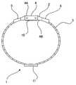
図1から図3には、本発明の実施形態の腕取り付け型携帯電話1を示す。図示されるように、腕取り付け型携帯電話1は、本体部2と、バンド部3とを備えている。Hereinafter, embodiments of the present invention will be described with reference to the accompanying drawings.
1 to 3 show an arm-mounted
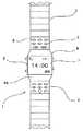
本体部2は、主部4と、操作部5、6とから構成される。操作部5、6は、主部4の上下両側に隣接して、主部4とバンド部3との間に配置されている。主部4の表面4Aには、例えば液晶画面からなる表示画面7が備えられる。一方、操作部5、6には、携帯電話1を操作するために必要な複数の操作ボタン8が配置されている。この場合、操作部5、6のそれぞれに、略同数の操作ボタン8が配置されている。 The
このように、表示画面7を備えた主部4の上下両側に操作部5、6を配置することにより、携帯電話1のインターフェースとして必要な構成を、使用者の手首付近にコンパクトに配置することができ、また主部4の表示画面7を十分大きなものとできる。また、使用者は、主部4の表示画面7を見ながら、主部4両側の操作部5、6の操作ボタン8を、それぞれ親指と人差し指で操作することができるので、携帯電話1は非常に操作しやすいものとできる。さらに、操作部5、6には略同数の操作ボタン8が配置されているので、使用者は親指と人差し指を略同程度に用いて操作することになり、操作が楽である。なお、表示画面7は、通常の携帯電話用画面を表示する画面としての他、テレビ電話用の画面としても用いることができる。 In this way, by arranging the
バンド部3は、両側の操作部5、6から延び出しており、使用者の手首の周囲に取り付け可能となっている。なお、バンド部3を使用者の手首に装着したとき、本体部2は、使用者の手の甲側の手首部分(手首の表側)に配置されるようになっている。 The
携帯電話1のバッテリー(電池)は、バンド部3内に収容されるようにしてもよい。これにより、本体部2を、バッテリーを含まない分だけ小型化できるので、携帯電話1を腕に装着した場合でも、本体部2が大きすぎて邪魔になることはない。 The battery (battery) of the
主部4の裏面4Bには、骨伝導スピーカ10が取り付けられている。ここで、骨伝導スピーカ10は、本体部2と電気的に接続され、本体部2からの信号に基づいて振動する振動体であり、使用者と接触して配置されたとき、その接触部位の骨に骨伝導を与える骨伝導振動体である。このように、骨伝導スピーカ10を主部4の裏面4Bに配置することにより、使用者が携帯電話1を手首に装着した場合に、骨伝導スピーカ10が、使用者の手の甲側において、ちょうど手首関節の骨の上に配置されることになる。これにより、骨伝導スピーカ10の振動は、使用者の前腕から手にかけての骨に適切に伝達される。 A
携帯電話1からの音声情報を聞く場合、使用者は、携帯電話1を装着した方の手を自らの耳に被せて配置する。これにより、耳に被せられた手が、骨伝導スピーカ10から伝達された骨伝導により振動すると、スピーカのように機能し、使用者は、自らの手から発せられる空気振動を音として聞くことができる。また、別法として、使用者は、携帯電話1を装着した方の手を自身の頭蓋骨に接触させる(例えば、手を耳付近に当てて配置する、又は頬骨に当てて配置する)。これにより、骨伝導スピーカ10からの骨導音が、使用者の手首及び手の骨から頭蓋骨さらには内耳に伝わり、使用者は、携帯電話1からの音声情報を取得することができる。 When listening to audio information from the
なお、携帯電話1への着信を知らせる場合にも、骨伝導スピーカ10を振動させるようにしても良い。
携帯電話1のバンド部3上には、音声取得用のマイク11が備えられる。マイク11は、バンド部3を挟んで本体部2と反対側に配置される。つまり、携帯電話1を装着したときに、手の平側の手首部分(手首の裏側)に配置される。これにより、使用者が携帯電話1で通話するために携帯電話1を装着した側の手を耳付近に配置すると、マイク11は、ちょうど使用者の口の近傍に配置され、使用者が発する音声を適切に取得することができるようになっている。It should be noted that the
On the
このように本実施形態の腕取り付け型携帯電話1によれば、携帯電話1を手首に装着すれば、骨伝導スピーカ10が使用者の手首外側の骨部分に接触するように配置されるので、使用者は、手を耳に被せて配置するか、あるいは手を頭蓋骨と接触させる(例えば、耳付近に当てて配置する、又は頬骨に当てて配置する)ことによって、携帯電話1からの音声情報を取得することができる。したがって、使用者は、容易な動作をするだけで、周囲に騒音がある場合でも、骨伝導スピーカ10からのクリアな音声を、第三者に聞かれることなく、楽な姿勢で取得できる。 As described above, according to the arm-mounted
また、使用者が自らの手を耳付近に配置した場合、使用者の手首内側付近に配置された音声取得用のマイク11は、使用者の口の近傍に配置されることになり、使用者は、そのままの姿勢で、骨伝導スピーカ10から骨導音を取得しながら、マイクに向けて話をすることができる。したがって、使用者は、携帯電話1を用いた通話を、自然な体勢で、楽に行うことができる。 In addition, when the user places his / her hand near the ear, the
また、携帯電話1への着信を骨伝導スピーカ10の振動で知らせるようにすれば、使用者は、手首付近に振動を感じることにより、携帯電話1への着信があったことを確実に知ることができる。 Further, if the incoming call to the
図4には、本発明の他の実施形態を示す。図示されるように、本実施形態では、携帯電話の骨伝導振動体である骨伝導スピーカ21を、使用者の指に装着可能なリング部22に取り付けて、指輪型スピーカ部20を構成している。なお、携帯電話の他の部分は、例えば、上記図1から図3の腕取り付け型携帯電話1から骨伝導スピーカ10を除いた構成に、本体部2からの信号を骨伝導スピーカ21に伝える無線機能を加えた構成を使用すればよい。このような指輪型スピーカ部20を使用する場合、使用者は、指輪型スピーカ部20を装着した指を耳の穴の中に挿入することにより、骨伝導スピーカ21からの骨導音を指の骨を介して取得することができる。 FIG. 4 shows another embodiment of the present invention. As shown in the figure, in the present embodiment, a ring-
なお、上記各実施形態では、骨伝導振動体(骨伝導スピーカ10、21)を腕取り付け型携帯電話1の本体部2の裏面(主部4の裏面4A)、又は指輪型スピーカ部20のリング部22に設ける例を示したが、本発明はこのような形態に限られるものではない。骨伝導振動体は、使用者の前腕から手にかけてのいずれかの部位に接触して装着できるものであれば良い。例えば、腕輪型の部材に骨伝導振動体を取り付けて、この骨伝導振動体が、使用者の前腕部に接触するようにしても良い。 In each of the above embodiments, the bone conduction vibrator (
また、骨伝導振動体と携帯電話本体は、信号が伝達できる形態であれば、有線によって結ばれていても、無線によって結ばれていてもよい。 Further, the bone conduction vibrator and the mobile phone main body may be connected by wire or wirelessly as long as a signal can be transmitted.
1 腕取り付け型携帯電話
2 本体部
3 バンド部
4 主部
4A 表面
4B 裏面
5 操作部
6 操作部
7 表示画面
8 操作ボタン
10 骨伝導スピーカ
11 マイク
20 指輪型スピーカ部
21 骨伝導スピーカ
22 リング部DESCRIPTION OF
Claims (9)
Translated fromJapanese使用者の前腕及び手の少なくとも一部に接触した状態で設置可能な振動体と、
前記携帯電話本体からの信号に基づいて前記振動体を振動させる手段と
を備えた骨伝導式携帯電話。A mobile phone body,
A vibrator that can be placed in contact with at least a portion of the user's forearm and hand; and
A bone conduction type mobile phone comprising: means for vibrating the vibrating body based on a signal from the mobile phone body.
Priority Applications (1)
| Application Number | Priority Date | Filing Date | Title |
|---|---|---|---|
| JP2005153703AJP2006333058A (en) | 2005-05-26 | 2005-05-26 | Bone conduction mobile phone |
Applications Claiming Priority (1)
| Application Number | Priority Date | Filing Date | Title |
|---|---|---|---|
| JP2005153703AJP2006333058A (en) | 2005-05-26 | 2005-05-26 | Bone conduction mobile phone |
Publications (1)
| Publication Number | Publication Date |
|---|---|
| JP2006333058Atrue JP2006333058A (en) | 2006-12-07 |
Family
ID=37554274
Family Applications (1)
| Application Number | Title | Priority Date | Filing Date |
|---|---|---|---|
| JP2005153703APendingJP2006333058A (en) | 2005-05-26 | 2005-05-26 | Bone conduction mobile phone |
Country Status (1)
| Country | Link |
|---|---|
| JP (1) | JP2006333058A (en) |
Cited By (30)
| Publication number | Priority date | Publication date | Assignee | Title |
|---|---|---|---|---|
| JP2009071402A (en)* | 2007-09-11 | 2009-04-02 | Seiko Epson Corp | Wrist watch type mobile phone |
| US7745717B2 (en) | 2007-03-16 | 2010-06-29 | Yamaha Corporation | Wearable electronic device |
| WO2012114917A1 (en)* | 2011-02-25 | 2012-08-30 | ローム株式会社 | Talk system and finger ring for talk system |
| JP2013090138A (en)* | 2011-10-18 | 2013-05-13 | Yuji Hosoi | Sound output device |
| CN103973853A (en)* | 2014-01-16 | 2014-08-06 | 张小成 | Moving equipment with bone conduction function |
| JP2015061285A (en)* | 2013-09-20 | 2015-03-30 | 株式会社ファインウェル | Call transmission/reception device and call transmission/reception method |
| JP2015082818A (en)* | 2013-10-24 | 2015-04-27 | 株式会社ファインウェル | Transmitter / receiver |
| JP2015099974A (en)* | 2013-11-18 | 2015-05-28 | 株式会社ファインウェル | Reception method and transmission / reception apparatus |
| JP2015139132A (en)* | 2014-01-23 | 2015-07-30 | 株式会社ファインウェル | Notification device |
| JP2015216677A (en)* | 2015-07-07 | 2015-12-03 | 株式会社ファインウェル | Conversation system, finger ring for conversation system, finger ring for mobile phone, finger ring type mobile phone, and voice hearing method |
| US9313306B2 (en) | 2010-12-27 | 2016-04-12 | Rohm Co., Ltd. | Mobile telephone cartilage conduction unit for making contact with the ear cartilage |
| EP3024250A1 (en)* | 2014-11-18 | 2016-05-25 | Center for Integrated Smart Sensors Foundation | Wearable device using bone conduction speaker |
| US9392097B2 (en) | 2010-12-27 | 2016-07-12 | Rohm Co., Ltd. | Incoming/outgoing-talk unit and incoming-talk unit |
| US9479624B2 (en) | 2012-01-20 | 2016-10-25 | Rohm Co., Ltd. | Mobile telephone |
| WO2016175468A1 (en)* | 2015-04-27 | 2016-11-03 | 주식회사 아모그린텍 | Wearable device |
| KR101680790B1 (en) | 2015-10-12 | 2016-11-29 | 매칭시스템주식회사 | Finger weartype bone conduction speaker |
| US9705548B2 (en) | 2013-10-24 | 2017-07-11 | Rohm Co., Ltd. | Wristband-type handset and wristband-type alerting device |
| US9729971B2 (en) | 2012-06-29 | 2017-08-08 | Rohm Co., Ltd. | Stereo earphone |
| US9742887B2 (en) | 2013-08-23 | 2017-08-22 | Rohm Co., Ltd. | Mobile telephone |
| US10013862B2 (en) | 2014-08-20 | 2018-07-03 | Rohm Co., Ltd. | Watching system, watching detection device, and watching notification device |
| KR101940616B1 (en)* | 2017-11-07 | 2019-01-22 | ㈜건융아이비씨 | Digital voice amplifying system |
| US10356231B2 (en) | 2014-12-18 | 2019-07-16 | Finewell Co., Ltd. | Cartilage conduction hearing device using an electromagnetic vibration unit, and electromagnetic vibration unit |
| JP2019140447A (en)* | 2018-02-07 | 2019-08-22 | 国立大学法人千葉大学 | Acoustic transmission method |
| US10778824B2 (en) | 2016-01-19 | 2020-09-15 | Finewell Co., Ltd. | Pen-type handset |
| US10795321B2 (en) | 2015-09-16 | 2020-10-06 | Finewell Co., Ltd. | Wrist watch with hearing function |
| US10967521B2 (en) | 2015-07-15 | 2021-04-06 | Finewell Co., Ltd. | Robot and robot system |
| CN113766373A (en)* | 2020-06-03 | 2021-12-07 | 北京字节跳动网络技术有限公司 | Wearable device |
| US11224351B2 (en) | 2015-04-27 | 2022-01-18 | Amogreentech Co., Ltd. | Wearable device |
| IT202000032465A1 (en)* | 2020-12-24 | 2022-06-24 | Deed S R L | WEARABLE DEVICE TO MAKE AN AUDIO COMMUNICATION THROUGH BONE CONDUCTION AND TO DETECT VITAL SIGNS, AND RELATED SYSTEM AND METHOD |
| US11526033B2 (en) | 2018-09-28 | 2022-12-13 | Finewell Co., Ltd. | Hearing device |
- 2005
- 2005-05-26JPJP2005153703Apatent/JP2006333058A/enactivePending
Cited By (53)
| Publication number | Priority date | Publication date | Assignee | Title |
|---|---|---|---|---|
| US7745717B2 (en) | 2007-03-16 | 2010-06-29 | Yamaha Corporation | Wearable electronic device |
| JP2009071402A (en)* | 2007-09-11 | 2009-04-02 | Seiko Epson Corp | Wrist watch type mobile phone |
| US9392097B2 (en) | 2010-12-27 | 2016-07-12 | Rohm Co., Ltd. | Incoming/outgoing-talk unit and incoming-talk unit |
| US9716782B2 (en) | 2010-12-27 | 2017-07-25 | Rohm Co., Ltd. | Mobile telephone |
| US9894430B2 (en) | 2010-12-27 | 2018-02-13 | Rohm Co., Ltd. | Incoming/outgoing-talk unit and incoming-talk unit |
| US10779075B2 (en) | 2010-12-27 | 2020-09-15 | Finewell Co., Ltd. | Incoming/outgoing-talk unit and incoming-talk unit |
| US9313306B2 (en) | 2010-12-27 | 2016-04-12 | Rohm Co., Ltd. | Mobile telephone cartilage conduction unit for making contact with the ear cartilage |
| US9020170B2 (en) | 2011-02-25 | 2015-04-28 | Rohm Co., Ltd. | Hearing system and finger ring for the hearing system |
| US9485559B2 (en) | 2011-02-25 | 2016-11-01 | Rohm Co., Ltd. | Hearing system and finger ring for the hearing system |
| US9980024B2 (en) | 2011-02-25 | 2018-05-22 | Rohm Co., Ltd. | Hearing system and finger ring for the hearing system |
| JP2012178695A (en)* | 2011-02-25 | 2012-09-13 | Yuji Hosoi | Conversation system, ring for conversation system, ring for mobile phone, ring type mobile phone, and voice listening method |
| WO2012114917A1 (en)* | 2011-02-25 | 2012-08-30 | ローム株式会社 | Talk system and finger ring for talk system |
| JP2013090138A (en)* | 2011-10-18 | 2013-05-13 | Yuji Hosoi | Sound output device |
| US10158947B2 (en) | 2012-01-20 | 2018-12-18 | Rohm Co., Ltd. | Mobile telephone utilizing cartilage conduction |
| US10079925B2 (en) | 2012-01-20 | 2018-09-18 | Rohm Co., Ltd. | Mobile telephone |
| US10778823B2 (en) | 2012-01-20 | 2020-09-15 | Finewell Co., Ltd. | Mobile telephone and cartilage-conduction vibration source device |
| US9479624B2 (en) | 2012-01-20 | 2016-10-25 | Rohm Co., Ltd. | Mobile telephone |
| US10506343B2 (en) | 2012-06-29 | 2019-12-10 | Finewell Co., Ltd. | Earphone having vibration conductor which conducts vibration, and stereo earphone including the same |
| US9729971B2 (en) | 2012-06-29 | 2017-08-08 | Rohm Co., Ltd. | Stereo earphone |
| US10834506B2 (en) | 2012-06-29 | 2020-11-10 | Finewell Co., Ltd. | Stereo earphone |
| US10075574B2 (en) | 2013-08-23 | 2018-09-11 | Rohm Co., Ltd. | Mobile telephone |
| US9742887B2 (en) | 2013-08-23 | 2017-08-22 | Rohm Co., Ltd. | Mobile telephone |
| US10237382B2 (en) | 2013-08-23 | 2019-03-19 | Finewell Co., Ltd. | Mobile telephone |
| JP2015061285A (en)* | 2013-09-20 | 2015-03-30 | 株式会社ファインウェル | Call transmission/reception device and call transmission/reception method |
| JP2015082818A (en)* | 2013-10-24 | 2015-04-27 | 株式会社ファインウェル | Transmitter / receiver |
| US9705548B2 (en) | 2013-10-24 | 2017-07-11 | Rohm Co., Ltd. | Wristband-type handset and wristband-type alerting device |
| TWI648653B (en)* | 2013-10-24 | 2019-01-21 | 日商精良股份有限公司 | Bracelet type speaking device |
| US10103766B2 (en) | 2013-10-24 | 2018-10-16 | Rohm Co., Ltd. | Wristband-type handset and wristband-type alerting device |
| JP2015099974A (en)* | 2013-11-18 | 2015-05-28 | 株式会社ファインウェル | Reception method and transmission / reception apparatus |
| CN103973853A (en)* | 2014-01-16 | 2014-08-06 | 张小成 | Moving equipment with bone conduction function |
| JP2015139132A (en)* | 2014-01-23 | 2015-07-30 | 株式会社ファインウェル | Notification device |
| US10380864B2 (en) | 2014-08-20 | 2019-08-13 | Finewell Co., Ltd. | Watching system, watching detection device, and watching notification device |
| US10013862B2 (en) | 2014-08-20 | 2018-07-03 | Rohm Co., Ltd. | Watching system, watching detection device, and watching notification device |
| EP3024250A1 (en)* | 2014-11-18 | 2016-05-25 | Center for Integrated Smart Sensors Foundation | Wearable device using bone conduction speaker |
| US9681222B2 (en) | 2014-11-18 | 2017-06-13 | Center For Integrated Smart Sensors Foundation | Wearable device using bone conduction speaker |
| CN105611468A (en)* | 2014-11-18 | 2016-05-25 | 财团法人多次元智能It融合系统 | Wearable device using bone conduction speaker |
| US10356231B2 (en) | 2014-12-18 | 2019-07-16 | Finewell Co., Ltd. | Cartilage conduction hearing device using an electromagnetic vibration unit, and electromagnetic vibration unit |
| US10848607B2 (en) | 2014-12-18 | 2020-11-24 | Finewell Co., Ltd. | Cycling hearing device and bicycle system |
| US11601538B2 (en) | 2014-12-18 | 2023-03-07 | Finewell Co., Ltd. | Headset having right- and left-ear sound output units with through-holes formed therein |
| US11224351B2 (en) | 2015-04-27 | 2022-01-18 | Amogreentech Co., Ltd. | Wearable device |
| WO2016175468A1 (en)* | 2015-04-27 | 2016-11-03 | 주식회사 아모그린텍 | Wearable device |
| JP2015216677A (en)* | 2015-07-07 | 2015-12-03 | 株式会社ファインウェル | Conversation system, finger ring for conversation system, finger ring for mobile phone, finger ring type mobile phone, and voice hearing method |
| US10967521B2 (en) | 2015-07-15 | 2021-04-06 | Finewell Co., Ltd. | Robot and robot system |
| US10795321B2 (en) | 2015-09-16 | 2020-10-06 | Finewell Co., Ltd. | Wrist watch with hearing function |
| KR101680790B1 (en) | 2015-10-12 | 2016-11-29 | 매칭시스템주식회사 | Finger weartype bone conduction speaker |
| US10778824B2 (en) | 2016-01-19 | 2020-09-15 | Finewell Co., Ltd. | Pen-type handset |
| KR101940616B1 (en)* | 2017-11-07 | 2019-01-22 | ㈜건융아이비씨 | Digital voice amplifying system |
| JP2019140447A (en)* | 2018-02-07 | 2019-08-22 | 国立大学法人千葉大学 | Acoustic transmission method |
| JP7220444B2 (en) | 2018-02-07 | 2023-02-10 | 国立大学法人千葉大学 | Acoustic transmission system |
| US11526033B2 (en) | 2018-09-28 | 2022-12-13 | Finewell Co., Ltd. | Hearing device |
| CN113766373A (en)* | 2020-06-03 | 2021-12-07 | 北京字节跳动网络技术有限公司 | Wearable device |
| IT202000032465A1 (en)* | 2020-12-24 | 2022-06-24 | Deed S R L | WEARABLE DEVICE TO MAKE AN AUDIO COMMUNICATION THROUGH BONE CONDUCTION AND TO DETECT VITAL SIGNS, AND RELATED SYSTEM AND METHOD |
| WO2022137041A1 (en)* | 2020-12-24 | 2022-06-30 | Deed S.R.L. | Wearable device for effecting an audio communication via bone conduction and for detecting vital signals, and system and method thereof |
Similar Documents
| Publication | Publication Date | Title |
|---|---|---|
| JP2006333058A (en) | Bone conduction mobile phone | |
| KR101604521B1 (en) | Transmitter/receiver unit and receiver unit | |
| KR101704155B1 (en) | Portable telephone having cartilage conduction section | |
| KR101973486B1 (en) | Cartilage conduction hearing device using an electromagnetic vibration unit, and electromagnetic vibration unit | |
| US8325963B2 (en) | Bone-conduction microphone built-in headset | |
| JP6282025B2 (en) | mobile phone | |
| JP6513839B2 (en) | Listening device using bone conduction | |
| CN101753221A (en) | Butterfly temporal bone conduction communication and/or hearing aid device | |
| WO2000076184A1 (en) | Mobile communication unit with bone conduction speaker | |
| KR100779145B1 (en) | Multifunction wrist watch | |
| JP6012146B2 (en) | mobile phone | |
| JP6022175B2 (en) | Cartilage conduction vibration source device | |
| JP2013042464A (en) | Cellular phone | |
| JP2009071402A (en) | Wrist watch type mobile phone | |
| JP6316897B2 (en) | Cartilage conduction vibration source module | |
| JP2017028737A (en) | Call transceiver unit for mobile phone | |
| JP6022169B2 (en) | Mobile phone and receiver unit for mobile phone | |
| JP2000092170A (en) | Wearable wireless telephone | |
| JP2013005114A (en) | Mobile phone | |
| JP2005175764A (en) | Wearable voice receiving apparatus and wearable voice communication apparatus | |
| JP2001251404A (en) | Radio communication apparatus | |
| JP2013187887A (en) | Portable telephone |
Legal Events
| Date | Code | Title | Description |
|---|---|---|---|
| A977 | Report on retrieval | Effective date:20070309 Free format text:JAPANESE INTERMEDIATE CODE: A971007 | |
| A131 | Notification of reasons for refusal | Free format text:JAPANESE INTERMEDIATE CODE: A131 Effective date:20070315 | |
| A02 | Decision of refusal | Free format text:JAPANESE INTERMEDIATE CODE: A02 Effective date:20070823 |