JP2006331307A - Distributed system - Google Patents
Distributed systemDownload PDFInfo
- Publication number
- JP2006331307A JP2006331307AJP2005157598AJP2005157598AJP2006331307AJP 2006331307 AJP2006331307 AJP 2006331307AJP 2005157598 AJP2005157598 AJP 2005157598AJP 2005157598 AJP2005157598 AJP 2005157598AJP 2006331307 AJP2006331307 AJP 2006331307A
- Authority
- JP
- Japan
- Prior art keywords
- communication
- software defined
- defined radio
- component
- radio
- Prior art date
- Legal status (The legal status is an assumption and is not a legal conclusion. Google has not performed a legal analysis and makes no representation as to the accuracy of the status listed.)
- Pending
Links
- 238000010276constructionMethods0.000claimsdescription10
- 230000008859changeEffects0.000claimsdescription2
- 230000006854communicationEffects0.000abstractdescription252
- 238000004891communicationMethods0.000abstractdescription230
- 238000000034methodMethods0.000description72
- 230000008569processEffects0.000description61
- 238000012545processingMethods0.000description36
- 230000004044responseEffects0.000description24
- 238000010586diagramMethods0.000description15
- 238000001994activationMethods0.000description8
- 230000005540biological transmissionEffects0.000description8
- 238000004092self-diagnosisMethods0.000description8
- 230000004913activationEffects0.000description7
- 238000012217deletionMethods0.000description7
- 230000037430deletionEffects0.000description7
- 238000006243chemical reactionMethods0.000description4
- 239000000872bufferSubstances0.000description2
- 230000006870functionEffects0.000description2
- 238000002360preparation methodMethods0.000description2
- 230000005236sound signalEffects0.000description2
- 238000004904shorteningMethods0.000description1
- 238000012360testing methodMethods0.000description1
Images


Landscapes
- Transceivers (AREA)
- Stored Programmes (AREA)
Abstract
Translated fromJapaneseDescription
Translated fromJapanese本発明は、クライアントサーバシステムなどの分散システムに関する。 The present invention relates to a distributed system such as a client server system.
複数のオブジェクト間で通信を行うことによりアプリケーションを構築する分散システムとして、オブジェクトの組合わせを変更することによって、アプリケーションを切り替えるものが知られている。
例えば、特許文献1は、複数のオブジェクト間で通信を行うことによりソフトウェア無線機を構成し、ユーザが指定した無線方式の名前に応じてオブジェクトの接続を変更することにより、ソフトウェア無線機の無線方式を変更することを開示する。
しかしながら、上記従来例においては、運用中の無線方式を実現するオブジェクト群と、新たに切り替えられる無線方式を実現するオブジェクト群とが同一であっても、全く異なるオブジェクト群を起動して無線方式を変更する場合と同様の手順によらなければ、無線方式を変更することができず、アプリケーションの切り替え時間を短縮することができないという問題があった。As a distributed system that constructs an application by communicating between a plurality of objects, a system that switches applications by changing the combination of objects is known.
For example,
However, in the above conventional example, even if the object group that realizes the operating wireless method and the object group that realizes the newly switched wireless method are the same, a completely different object group is activated to set the wireless method. If the same procedure as in the case of changing is not followed, there is a problem that the radio system cannot be changed and the application switching time cannot be shortened.
本発明は、上述した背景からなされたものであり、アプリケーションの切り替え時間を短縮することができる分散システムを提供することを目的とする。 The present invention has been made from the above-described background, and an object of the present invention is to provide a distributed system capable of shortening an application switching time.
[分散システム]
上記目的を達成するために、本発明に係る分散システムは、複数のオブジェクトを記憶するサーバと、前記サーバに対するクライアントと、オブジェクトの組合わせ情報、オブジェクトの取得要否およびアプリケーションを変更すべき指示を含む制御情報を前記クライアントに対して出力する制御部とを含む分散システムであって、前記クライアントは、前記制御部が出力した制御情報に応じて、前記サーバからオブジェクトを取得するオブジェクト取得手段と、前記制御部が出力した制御情報に応じて、オブジェクトを組合わせてアプリケーションを構築するアプリケーション構築手段とを有する。[Distributed system]
In order to achieve the above object, a distributed system according to the present invention provides a server for storing a plurality of objects, a client for the server, combination information of objects, necessity of acquisition of objects, and an instruction to change an application. A distributed system including a control unit that outputs control information to the client, wherein the client acquires an object from the server in accordance with the control information output by the control unit; Application construction means for constructing an application by combining objects according to the control information output by the control section.
本発明に係る分散システムは、アプリケーションの切り替え時間を短縮することができる。 The distributed system according to the present invention can shorten the application switching time.
[本発明の背景]
まず、本発明の理解を助けるために、実施形態の説明に先立ち、その背景を説明する。
ソフトウェア無線機は、例えば無線方式ごとに異なる複数のソフトウェアの組合わせを切り替えてアプリケーションを構築することにより、無線方式を切り替えて無線通信を行うことができるようにされている。
しかしながら、ソフトウェア無線機を多数の無線方式に対応させるために、無線方式ごとに異なる多数のソフトウェアの全てをソフトウェア無線機内に保持させると、ソフトウェア無線機に過剰な容量のメモリが必要になるので、ハードウェアを有効に利用することができなくなってしまう。[Background of the present invention]
First, in order to help understanding of the present invention, the background will be described prior to the description of the embodiments.
The software defined radio is configured to perform wireless communication by switching between wireless systems, for example, by building an application by switching a combination of a plurality of different software for each wireless system.
However, in order to make the software defined radio compatible with a large number of wireless systems, if all of a large number of different software for each wireless system is held in the software defined radio, the software defined radio requires an excessive amount of memory. The hardware cannot be used effectively.
ソフトウェア無線機を多数の無線方式に対応させる場合には、無線方式ごとに異なる多数のソフトウェアの全てをサーバが記憶し、クライアントとなるソフトウェア無線機が新たに切り替えられる無線方式に必要なソフトウェア群を選択してサーバから取得し、取得したソフトウェア群から無線方式に対応したアプリケーションを構築するように制御することにより、ソフトウェア無線機のハードウェアを有効に利用することができる。
このように、クライアントのアプリケーションを切り替える場合には、クライアントが運用中のソフトウェア群を終了させて削除し、新たに切り替えられるアプリケーションを構築するソフトウェア群をクライアントがサーバから取得して起動し、切り替えられるアプリケーションを構築する方法が採られることが多い。When making software radios compatible with multiple radio systems, the server stores all of the software that differs for each radio system, and the software group necessary for the radio system in which a software radio that becomes a client can be newly switched By selecting and acquiring from the server and controlling to build an application corresponding to the wireless system from the acquired software group, the hardware of the software defined radio can be used effectively.
As described above, when a client application is switched, the software group in operation by the client is terminated and deleted, and the client acquires a software group for constructing a newly switched application from the server, and is activated and switched. In many cases, an application is built.
しかしながら、クライアントが運用中のソフトウェア群を終了させて削除し、新たに切り替えられるアプリケーションを構築する場合、クライアントが運用中のアプリケーションを構築するソフトウェア群と、新たに切り替えれらるアプリケーションを構築するソフトウェア群とが同一であっても、全く異なるソフトウェア群を起動してアプリケーションを切り替える場合と同じ手順でアプリケーションを切り替えることになる。
また、クライアントが運用中のアプリケーションを構築するソフトウェア群と、新たに切り替えれらるアプリケーションを構築するソフトウェア群とが同一である場合に、クライアントが運用中のアプリケーションを構築しているソフトウェア群を使用して新たに切り替えれらるアプリケーションを構築するためには、ソフトウェアが正しいバージョンであるか否かを確認する必要があり、各ソフトウェアを照合するとバージョンの確認に時間がかかってしまう。However, when building a new switchable application by closing and deleting the software group that the client is operating, the software group that constructs the application that the client is operating and the software group that constructs the application that can be switched newly Even if they are the same, the application is switched in the same procedure as when switching an application by starting a completely different software group.
In addition, when the software group that builds the application that the client is operating is the same as the software group that builds the application that can be newly switched, use the software group that builds the application that the client is operating. In order to construct an application that can be newly switched, it is necessary to check whether or not the software is the correct version. It takes time to check the version if each software is checked.
本発明は、このような背景からなされ、クライアントがハードウェアを効率的に利用しつつ、ソフトウェアによるアプリケーションの切り替え時間を短縮することができるようにされている。 The present invention is made from such a background, so that the client can efficiently use the hardware, and the application switching time by the software can be shortened.
[実施形態]
以下、本発明の実施形態を説明する。[Embodiment]
Embodiments of the present invention will be described below.
[システム構成]
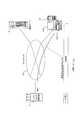
図1は、本発明に係る分散システム1の構成を例示する図である。
図1に示すように、分散システム1は、通信サーバ2、ソフトウェア無線機3、および、通信制御部10が有線または無線のネットワーク12を介して接続された構成を採る。
通信サーバ2は、複数の無線方式(図6などを用いて後述)に対応する無線機をソフトウェアにより構成するための複数のコンポーネント(オブジェクトを含むソフトウェアコンポーネント)およびパラメータを後述するコンポーネントDB(データベース)20に記憶し、ソフトウェア無線機3からの要求に応じてコンポーネントおよびパラメータ(動作モード等)をソフトウェア無線機3に対して出力(提供)する。[System configuration]
FIG. 1 is a diagram illustrating the configuration of a
As shown in FIG. 1, the
The
通信制御部10は、例えばパーソナルコンピュータであり、キーボードなどの入力装置100および表示装置102などを含み、ユーザ(システム管理者)が入力装置100を操作することにより、ネットワーク12を介してソフトウェア無線機3を制御することができるようにされている。
例えば通信制御部10は、ユーザの操作に応じて、無線方式を示す通信諸元設定要求電文4をソフトウェア無線機3に対して出力することにより、ソフトウェア無線機3を所定の無線方式の無線機に切り替える。The
For example, the
[ソフトウェア無線機3]
図2は、図1に示したソフトウェア無線機3の構成を例示する図であって、ソフトウェア無線機3がAM音声アナログ通信を行うように設定された状態を示す構成図である。
ソフトウェア無線機3は、通信サーバ2のクライアントであり、基本構成部30と、この基本構成部30を制御するコントロールユニット32とを有し、通信制御部10から受け入れた通信諸元設定要求電文4に応じて後述する対応テーブル310を参照し、通信サーバ2から取得するオブジェクトの組合わせを切り替えることにより、複数の無線方式に対応する無線機を構成する。[Software radio 3]
FIG. 2 is a diagram illustrating the configuration of the software defined
The software defined
基本構成部30は、第1のA/D・D/A変換部300、プログラマブルモデムプロセッサ302、第2のA/D・D/A変換部304、RFユニット306およびプロトコルスタックユニット308から構成される。 The
第1のA/D・D/A変換部300は、コントロールユニット32の制御に応じて、ソフトウェア無線機3に対して入力されるアナログの音声信号および映像信号をA/D変換し、プログラマブルモデムプロセッサ302に対して出力するとともに、プログラマブルモデムプロセッサ302から入力されるデジタルの音声信号および映像信号をD/A変換し、ソフトウェア無線機3から出力する。
プログラマブルモデムプロセッサ302は、例えば300MHzのクロックで動作するDSPおよびメモリ(ともに図示せず)を含み、コントロールユニット32の制御に応じて、基本構成部30を構成する他の部分とともに所定の無線方式のモデムを構成するプログラマブルプロセッサである。The first A / D / D /
The
第2のA/D・D/A変換部304は、コントロールユニット32の制御に応じて、プログラマブルモデムプロセッサ302から入力されるデジタル信号をD/A変換し、RFユニット306に対して出力するとともに、RFユニット306から入力されるアナログ信号をA/D変換し、プログラマブルモデムプロセッサ302に対して出力する。
RFユニット306は、コントロールユニット32の制御に応じて電波を送受信するアンテナを含み、第2のA/D・D/A変換部304から入力されたアナログ信号を所定の周波数の電波として送信するとともに、受信した信号を第2のA/D・D/A変換部304に対して出力する。The second A / D / D / A converter 304 D / A converts the digital signal input from the
The
プロトコルスタックユニット308は、コントロールユニット32の制御に応じて所定のプロトコルスタックを設定し、所定のプロトコルでソフトウェア無線機3に対して入力されるデータをプログラマブルモデムプロセッサ302に対して出力するとともに、プログラマブルモデムプロセッサ302から入力されるデータを所定のプロトコルでソフトウェア無線機3から出力する。 The
コントロールユニット32は、例えば300MHzのクロックで動作するCPU、および、所定の無線方式の通信アプリケーションを構成するために起動される複数のコンポーネント(オブジェクトを含むソフトウェアコンポーネント)と、複数のコンポーネントを組合わせて所定の無線方式の通信アプリケーションを作成する通信アプリケーション作成プログラムとから構成される通信プログラム5を記憶するメモリを有する。 The
図2に示すように、ソフトウェア無線機3が例えばAM音声アナログ通信を行うように設定された(切り替えられた)場合、通信プログラム5は、アナログ送受信IF(インターフェイス)、音声通信、DSPアダプタ送信、DSPアダプタ受信、RF制御、RF制御IFおよびPB/CPL(パワーバンク/カプラ)制御IFの機能をそれぞれ実現する7つのコンポーネント(オブジェクトを含むソフトウェアコンポーネント)50−1〜50−7と、コンポーネント50−1〜50−7を組合わせてAM音声アナログ通信を行う通信アプリケーションを作成するための通信アプリケーション作成プログラム52とを有する。
コンポーネント50−1〜50−7は、分散処理ミドルウェアの機能の一部であるORB(Object Request Broker)を介して通信アプリケーション作成プログラム52とともに接続されており、通信アプリケーション作成プログラム52の処理に応じて、AM音声アナログ通信を実現する通信アプリケーション(通信プログラム)を構築する。As shown in FIG. 2, when the software defined
The components 50-1 to 50-7 are connected together with the communication
コントロールユニット32は、ソフトウェア無線機3が他の無線方式の通信アプリケーションを実行するように設定された場合には、他の無線方式の通信アプリケーションを構築するための複数のコンポーネントを起動させるようになっている。 When the software defined
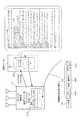
図3は、ORBを介して接続された通信アプリケーション作成プログラム52およびコンポーネント50−1〜50−7の概念を示す通信プログラム5の概念図である。
なお、コンポーネント50−1〜50−7はそれぞれ同様の構成になっており、図3においては、コンポーネント50−2(音声通信コンポーネント)の構成を中心に通信プログラム5の概念が示されている。
また、通信アプリケーション作成プログラム52およびコンポーネント50−1〜50−7に含まれるモジュール(オブジェクトの論理的なグループ)間の通信においては、サービスを依頼するモジュールがクライアント(クライアントモジュール)であり、サービスを提供するモジュールがサーバ(サーバモジュール)である。FIG. 3 is a conceptual diagram of the
The components 50-1 to 50-7 have the same configuration, and FIG. 3 shows the concept of the
In the communication between the communication
図3に示すように、例えばコンポーネント50−2(音声通信コンポーネント)は、起動処理モジュール500、動作モード設定サーバモジュール502、コンポーネント初期化サーバモジュール504、自己診断サーバモジュール506、コンポーネント接続サーバモジュール508、運用開始サーバモジュール510、プロセス終了サーバモジュール512、コンポーネント削除サーバモジュール514、クライアントモジュール群516およびサーバモジュール群518を有する。
起動処理モジュール500は、コンポーネント50−2に含まれる各モジュールを起動し、コンポーネント50−2の立上がり時にコンポーネント50−2のORB環境を初期化するとともに、ネーミングサービスのオブジェクトリファレンスを取得する。また、起動処理モジュール500は、後述するサーバモジュール群518をコンポーネント50−4から使用できるようにORBに登録する。As shown in FIG. 3, for example, the component 50-2 (voice communication component) includes a
The
動作モード設定サーバモジュール502は、通信アプリケーション作成プログラム52に含まれるアプリケーション作成クライアントモジュール520のコールに応じて、コンポーネント50−2の立上がり時に動作モードを設定する。
なお、動作モードには、通信系を作り上げるために必要なコンフィグレーション情報が含まれるようにされてもよい。
コンポーネント初期化サーバモジュール504は、アプリケーション作成クライアントモジュール520のコールに応じて、コンポーネント50−2による音声通信処理に必要なメモリ領域に設けられた変数に初期値を設定する。The operation mode setting server module 502 sets an operation mode when the component 50-2 starts up in response to a call from the application
The operation mode may include configuration information necessary for creating a communication system.
The component
自己診断サーバモジュール506は、アプリケーション作成クライアントモジュール520のコールに応じて、コンポーネント50−2の立上がり時に、自己診断テストを実行する。
コンポーネント接続サーバモジュール508は、アプリケーション作成クライアントモジュール520のコールに応じて、コンポーネント50−2の立上がり時に、クライアントモジュール群516が使用するコンポーネント50−3のサーバモジュール群518のアクセス情報(サーバオブジェクトリファレンス)をネーミングサービスにより取得する(コンポーネント接続処理)。The self-diagnosis server module 506 executes a self-diagnosis test when the component 50-2 starts up in response to a call from the application
The component
運用開始サーバモジュール510は、アプリケーション作成クライアントモジュール520のコールに応じて、コンポーネント50−2の立上がり時に、プロセス起動が完了したことを通信アプリケーション作成プログラム52に対して通知し、コンポーネント50−2の運用を開始させる。 In response to a call from the application
プロセス終了サーバモジュール512は、コンポーネント50−2の運用終了時におけるアプリケーション作成クライアントモジュール520からのコールに応じて、コンポーネント50−2のプロセスを終了させる。
コンポーネント削除サーバモジュール514は、コンポーネント50−2の運用終了時におけるアプリケーション作成クライアントモジュール520からのコールに応じて、コンポーネント50−2を削除する。The process
The component
コンポーネント50−2は、クライアントモジュール群516がORBを介してコンポーネント50−3にサービスを依頼し、サーバモジュール群518がORBを介してコンポーネント50−4にサービスを提供することにより、音声通信処理を実現して通信機能の一部を構成する。 In the component 50-2, the
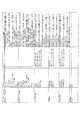
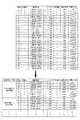
図4は、通信プログラム5が例えばAM音声アナログ通信プログラムを構築した場合に、ユーザがコンポーネント50−1〜50−7に対して設定可能な動作モード等を示す図表である。
図4に示すように、コンポーネント50−1〜50−7には、それぞれ必要に応じてプロパティ(属性)が設けられており、プロパティごとに動作モードを示す数値または対応するデバイス名などを設定することができるようにされている。FIG. 4 is a chart showing operation modes and the like that can be set by the user for the components 50-1 to 50-7 when the
As shown in FIG. 4, the components 50-1 to 50-7 are each provided with a property (attribute) as necessary, and a numerical value indicating an operation mode or a corresponding device name is set for each property. Have been able to.
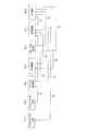
図5は、通信プログラム5がAM音声アナログ通信を実現する通信アプリケーション(通信プログラム)を構築した場合に、ORBを介して接続されるコンポーネント50−1〜50−7の接続例を示すブロック図である。
なお、図5においては、矢印の始点側のコンポーネントがクライアントモジュール群を含み、矢印の終点側のコンポーネントがサーバモジュール群を含むことにより、コンポーネント間が接続されていることが示されている。FIG. 5 is a block diagram showing a connection example of components 50-1 to 50-7 connected via the ORB when the
In FIG. 5, the components on the start point side of the arrow include a client module group, and the components on the end point side of the arrow include a server module group, thereby indicating that the components are connected.
図5に示すように、通信プログラム5がAM音声アナログ通信を実現する通信アプリケーションを構築した場合、9つのコンポーネント間接続が行われる。
すなわち、コンポーネント50−4(DSPアダプタ受信)およびコンポーネント50−1(アナログ送受信IF)それぞれのクライアントモジュールは、コンポーネント50−2(音声通信)のサーバモジュールを利用する(C1,C2)。
コンポーネント50−6(RF制御IF)、コンポーネント50−7(PB/CPL制御IF)およびコンポーネント50−2(音声通信)それぞれのクライアントモジュールは、コンポーネント50−5(RF制御)のサーバモジュールを利用する(C3,C4,C7)。
コンポーネント50−2(音声通信)のクライアントモジュールは、コンポーネント50−1(アナログ送受信IF)およびコンポーネント50−3(DSPアダプタ送信)それぞれのサーバモジュールを利用する(C5,C6)。
コンポーネント50−5(RF制御)のクライアントモジュールは、コンポーネント50−6(RF制御IF)およびコンポーネント50−7(PB/CPL制御IF)それぞれのサーバモジュールを利用する(C8,C9)。As shown in FIG. 5, when the
That is, the client modules of the component 50-4 (DSP adapter reception) and the component 50-1 (analog transmission / reception IF) use the server module of the component 50-2 (voice communication) (C1, C2).
Each client module of the component 50-6 (RF control IF), the component 50-7 (PB / CPL control IF), and the component 50-2 (voice communication) uses the server module of the component 50-5 (RF control). (C3, C4, C7).
The client module of the component 50-2 (voice communication) uses the respective server modules of the component 50-1 (analog transmission / reception IF) and the component 50-3 (DSP adapter transmission) (C5, C6).
The client module of the component 50-5 (RF control) uses the respective server modules of the component 50-6 (RF control IF) and the component 50-7 (PB / CPL control IF) (C8, C9).
次に、ソフトウェア無線機3を所定の無線方式の無線機に切り替えるために、通信制御部10(図1)が、ユーザの操作に応じて出力する通信諸元設定要求電文4について詳述する。
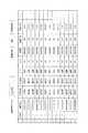
図6は、ソフトウェア無線機3に対して設定可能な複数の無線方式をユーザが選択して設定するために、通信制御部10の表示装置102が表示する入力画面例である。
図6に示すように、表示装置102は、無線方式を示す通信系名と、この通信系名が属する系番号、通信系名ごとの送受種別、送信出力、モード、バンド、周波数、変調方式および中間入力インターフェイス(IF)などを含む複数の通信諸元の組合わせを表示する。
表示装置102が表示した複数の通信諸元の組合わせの中から、ユーザが入力装置100を介して所定の無線方式を示す通信系名を選択することにより、通信制御部10は、ソフトウェア無線機3に対して通信諸元設定要求電文4を出力し、ソフトウェア無線機3を所定の無線方式の無線機に切り替える処理を開始するようにされている。Next, the communication specification
FIG. 6 is an example of an input screen displayed on the
As shown in FIG. 6, the
When the user selects a communication system name indicating a predetermined wireless system from the combination of a plurality of communication specifications displayed on the
図7は、ユーザの操作に応じて、通信制御部10が出力する通信諸元設定要求電文4の構成を示す図である。
図7に示すように、通信制御部10は、ユーザが入力装置100を介して選択した通信諸元の組合わせを記述する通信諸元記述部400に対し、後述する通信グループ名402およびダウンロード要フラグ404をそれぞれ前部および末部に付加して本体部40を形成し、本体部40を送信するためのヘッダ部42を配置することにより通信諸元設定要求電文4を構成する。FIG. 7 is a diagram illustrating a configuration of the communication specification
As shown in FIG. 7, the
[通信グループ名402]
図8は、通信制御部10(図1)が通信グループ名402によって特定する通信グループが包含する複数の通信系名を例示する図表である。
図9は、通信制御部10が設定する通信グループの第1の設定例を模式的に示す図表である。
図8に示すように、通信制御部10は、複数の通信系を包含する複数の通信グループを設定する。
例えば、図9に示すように、コンポーネントA,B,C,D,E,F,G,Hが異なる組合わせで接続されることによって複数の異なる通信系が構築される場合、通信制御部10は、コンポーネントA,B,C,D,E,F,G,Hを全て包含する通信グループを設定する。
つまり、通信制御部10は、コンポーネントA,B,C,D,E,F,G,Hが異なる組合わせで接続されることにより構築される通信系をソフトウェア無線機3に対して設定する場合、設定したコンポーネントA,B,C,D,E,F,G,Hの全てを包含する通信グループを特定する通信グループ名402を通信諸元設定要求電文4に付加することにより、ソフトウェア無線機3にコンポーネントA,B,C,D,E,F,G,Hの全てを取得させる。[Communication group name 402]
FIG. 8 is a chart illustrating a plurality of communication system names included in a communication group specified by the
FIG. 9 is a chart schematically illustrating a first setting example of a communication group set by the
As shown in FIG. 8, the
For example, as shown in FIG. 9, when a plurality of different communication systems are constructed by connecting components A, B, C, D, E, F, G, and H in different combinations, the
That is, the
したがって、コンポーネントの組合わせが異なる複数の通信系を1つの通信グループにまとめることができ、例えば切り替え時に設定すべき通信系ごとに通信グループを設定することにより、ハードウェアを効率的に利用することが可能になる。
通信グループの第1の設定例においては、所定の通信系を構築するために必要でないコンポーネントがメモリ上に存在する場合が生じるが、通信系を構築するために必要でないコンポーネントは停止しており、所定の通信系の構築に対して影響を与えない。Therefore, multiple communication systems with different combinations of components can be combined into one communication group. For example, hardware can be used efficiently by setting a communication group for each communication system to be set at the time of switching. Is possible.
In the first setting example of the communication group, there may be a case where a component that is not necessary for constructing a predetermined communication system exists in the memory, but a component that is not necessary for constructing the communication system is stopped, Does not affect the construction of a predetermined communication system.
図10は、通信制御部10(図1)が設定する通信グループの第2の設定例を模式的に示す図表である。
図10に示すように、例えばコンポーネントA,B,C,Eが起動され、接続されるモジュール、または、設定される動作モードなどが異なることによって異なる通信系が構築される場合、通信制御部10は、コンポーネントA,B,C,Eを起動する通信系を1つの通信グループ(CEグループ)として設定し、他の通信グループと区別する。
つまり、通信グループの第2の設定例は、同一のコンポーネントによって構築される通信系を1つの通信グループにまとめている。FIG. 10 is a chart schematically showing a second setting example of the communication group set by the communication control unit 10 (FIG. 1).
As shown in FIG. 10, for example, when the components A, B, C, and E are activated and different communication systems are constructed by different connected modules or different operation modes, the
That is, in the second setting example of the communication group, communication systems constructed by the same component are combined into one communication group.
[ダウンロード要フラグ404]
ダウンロード要フラグ404は、ソフトウェア無線機3が通信サーバ2からコンポーネントを取得する必要があるか否かを示すフラグであり、例えばソフトウェア無線機3が記憶している古いバージョンのコンポーネントを通信サーバ2が記憶している新しいバージョンのコンポーネントに置き換える必要がある場合などに、ユーザによって通信制御部10に対して設定される。[Download flag 404]
The
図11は、通信制御部10が送信した通信諸元設定要求電文4に応じて、通信サーバ2が記憶するコンポーネントをソフトウェア無線機3が取得する処理例を示す模式図である。
ソフトウェア無線機3は、通信制御部10から受信した通信諸元設定要求電文4に含まれる通信グループ名402をコントロールユニット32内のメモリ(図示せず)に記憶し、コントロールユニット32が記憶しているコンポーネントの組合わせを通信グループ名402によって特定するようにされている。FIG. 11 is a schematic diagram illustrating a processing example in which the software defined
The software defined
また、ソフトウェア無線機3は、通信制御部10(図1)から新たに通信諸元設定要求電文4を受信すると、記憶している通信グループ名と新たに受信した通信諸元設定要求電文4の通信グループ名402とを比較し、通信グループ名が一致しない場合には、通信グループ名とインデックスファイル名とを対応づけた対応テーブル310を参照し、新たに受信した通信諸元設定要求電文4に応じたインデックスファイル名を通信サーバ2に対して送信する。
さらに、ソフトウェア無線機3は、通信諸元設定要求電文4のダウンロード要フラグ404を読取ることにより、コンポーネントのバージョンアップなどにともなうコンポーネントの取得の要否を判定し、コンポーネントの取得が必要である場合には、必要なコンポーネントを包含する通信グループ名に対応するインデックスファイル名を通信サーバ2に対して送信する。Also, when the software defined
Furthermore, the software defined
通信サーバ2は、ソフトウェア無線機3からインデックスファイル名を取得すると、コンポーネントDB20に含まれるインデックスファイルDB(データベース)200からインデックスファイル名に対応するインデックスファイルを選択し、選択されたインデックスファイルに記載されたコンポーネント等をソフトウェア無線機3に対して例えばftpにより送信する。
なお、インデックスファイルDB200が記憶しているインデックスファイルは、通信グループに対応する複数のコンポーネントファイルおよびパラメータファイルがそれぞれファイル名、サイズ、相対パス名、パーミッション、実行時引数およびコメントなどを含む形式で記載されている。When the
The index file stored in the
次に、ソフトウェア無線機3が通信諸元設定要求電文4に応じて複数のコンポーネントを接続し、所定の無線方式の無線機を構成する処理について説明する。
図12は、ソフトウェア無線機3が電源投入により起動し、最初に所定の無線方式の無線機を構成する処理(起動時の構築処理:S10)を示すフローチャートである。
図12に示すように、ステップ100(S100)において、ソフトウェア無線機3は、通信諸元設定要求電文4に応じて所定の無線方式の無線機を構成するために必要なソフトウェアをコントロールユニット32が予め有しているか否かを判定し、必要なソフトウェアを有していない場合にはS102の処理に進み、必要なソフトウェアを有している場合にはS106の処理に進む。Next, a process in which the software defined
FIG. 12 is a flowchart showing a process (configuration process at start-up: S10) of starting the software defined
As shown in FIG. 12, in step 100 (S100), the software defined
ステップ102(S102)において、ソフトウェア無線機3は、通信諸元設定要求電文4の通信グループ名402とインデックスファイル名とを対応づけた対応テーブル310を参照し、通信諸元設定要求電文4に応じたインデックスファイル名を通信サーバ2に対して送信する。 In step 102 (S102), the software defined
ステップ104(S104)において、ソフトウェア無線機3は、必要なソフトウェア(コンポーネントおよびパラメータ)を例えばftpにより通信サーバ2から取得(ダウンロード)する。 In step 104 (S104), the software defined
ステップ106(S106)において、ソフトウェア無線機3は、コントロールユニット32が有する各コンポーネントを起動し、所定の起動パラメータを設定する。 In step 106 (S106), the software defined
ステップ108(S108)において、ソフトウェア無線機3は、各コンポーネント間を接続し、所定の無線方式の無線機を構成する。 In step 108 (S108), the software defined
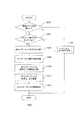
図13は、ソフトウェア無線機3が無線方式を切り替えて無線機を構成する処理(切替え時の構築処理:S20)を示すフローチャートである。
図14は、ソフトウェア無線機3がコンポーネントの取得をともなって無線方式を切り替えて無線機を構成する処理(コンポーネント取得切り替え処理:S30)を示すフローチャートである。
図13に示すように、ステップ200(S200)において、ソフトウェア無線機3は、通信制御部10から取得した通信諸元設定要求電文4の通信グループ名402と、コントロールユニット32が記憶している通信グループ名402とが等しいか否かを判定し、等しい場合にはS202の処理に進み、等しくない場合にはS30(図14)の処理に進む。
つまり、通信グループ名402は識別子であり、S200においては、通信諸元設定要求電文4に応じて構築されるべき無線方式の無線機を構成するために必要なコンポーネント等の全てが個々に照合等されることなく、ソフトウェア無線機3がコンポーネント等の全てを有しているか否かが判定される。FIG. 13 is a flowchart showing a process in which the software defined
FIG. 14 is a flowchart showing a process (component acquisition switching process: S30) in which the software defined
As shown in FIG. 13, in step 200 (S200), the software defined
That is, the
ステップ202(S202)において、ソフトウェア無線機3は、通信制御部10から取得した通信諸元設定要求電文4のダウンロード要フラグ404が立っているか否かを判定することにより、コンポーネントのバージョンアップなどにともなうコンポーネントの取得の要否を判定する。ソフトウェア無線機3は、ダウンロード要フラグ404が立っていない場合にはS204の処理に進み、立っている場合にはS30の処理に進む。 In step 202 (S202), the software defined
ステップ204(S204)において、ソフトウェア無線機3は、全コンポーネントのプロセスを終了させることにより、稼動中の通信プログラムを終了させる(コンポーネントのプロセス終了処理)。 In step 204 (S204), the software defined
ステップ206(S206)において、ソフトウェア無線機3は、コントロールユニット32内に記憶されているコンポーネント間をパラメータファイルの内容に応じて接続し、所定の無線方式の無線機を構成する(コンポーネントの接続処理)。
つまり、ソフトウェア無線機3は、通信諸元設定要求電文4に応じて切り替える無線方式に必要なコンポーネントを全て記憶しており、かつ、コンポーネントのバージョンアップ等も必要ない場合、新たにコンポーネントを取得することなく新しい通信プログラムを作成することができる。In step 206 (S206), the software defined
In other words, the software defined
ステップ208(S208)において、ソフトウェア無線機3は、通信諸元設定要求電文4に記載された全コンポーネントの動作モード情報を取得する(動作モードの取得処理)。 In step 208 (S208), the software defined
ステップ210(S210)において、ソフトウェア無線機3は、全コンポーネントの初期化および自己診断を行う。 In step 210 (S210), the software defined
ステップ212(S212)において、ソフトウェア無線機3は、全コンポーネントの運用を開始する(運用開始処理)。 In step 212 (S212), the software defined
図14に示すように、ステップ300(S300)において、ソフトウェア無線機3は、全コンポーネントのプロセスを終了させることにより、稼動中の通信プログラムを終了させる(コンポーネントのプロセス終了処理)。 As shown in FIG. 14, in step 300 (S300), the software defined
ステップ302(S302)において、ソフトウェア無線機3は、全コンポーネントをコントロールユニット32のメモリ上から削除する(コンポーネントの削除処理)。 In step 302 (S302), the software defined
ステップ304(S304)において、ソフトウェア無線機3は、通信制御部10から受入れた通信諸元設定要求電文4に記載された通信諸元を解析する。 In step 304 (S304), the software defined
ステップ306(S306)において、ソフトウェア無線機3は、S304の処理により解析した結果に応じて、新たに起動するコンポーネントを確定し、確定したコンポーネントを包含する通信グループ名に対応するインデックスファイル名を通信サーバ2に対して送信する。 In step 306 (S306), the software defined
ステップ308(S308)において、必要なソフトウェア(コンポーネントおよびパラメータ)を例えばftpにより通信サーバ2から取得(ダウンロード)する。 In step 308 (S308), necessary software (components and parameters) is acquired (downloaded) from the
ステップ310(S310)において、ソフトウェア無線機3は、取得した全コンポーネントを起動させる(コンポーネントの起動処理)。 In step 310 (S310), the software defined
ステップ312(S312)において、ソフトウェア無線機3は、起動させたコンポーネント間をパラメータファイルの内容に応じて接続し、所定の無線方式の無線機を構成する(コンポーネントの接続処理)。 In step 312 (S312), the software defined
ステップ314(S314)において、ソフトウェア無線機3は、通信諸元設定要求電文4に記載された全コンポーネントの動作モード情報を取得する(動作モードの取得処理)。 In step 314 (S314), the software defined
ステップ316(S316)において、ソフトウェア無線機3は、全コンポーネントの初期化および自己診断を行う。 In step 316 (S316), the software defined
ステップ318(S318)において、全コンポーネントの運用を開始する(運用開始処理)。 In step 318 (S318), operation of all components is started (operation start processing).
このように、ソフトウェア無線機3は、通信諸元設定要求電文4を受信すると、コンポーネントの取得要否を判定し、コンポーネントを取得する必要がないと判定した場合は、コンポーネントの削除処理およびコンポーネントの起動処理を行うことなく新たな無線方式の無線機を構成する。 As described above, when the software defined
[全体的動作]
以下、分散システム1(図1)の全体的な動作例を説明する。
図15は、図1に示した分散システム1において、ソフトウェア無線機3を立ち上げるシーケンス(S40)を示すシーケンス図である。[Overall operation]
Hereinafter, an overall operation example of the distributed system 1 (FIG. 1) will be described.
FIG. 15 is a sequence diagram showing a sequence (S40) for starting up the software defined
図15に示すように、ステップ400(S400)において、例えばユーザによりソフトウェア無線機3の電源が投入された場合などに、ソフトウェア無線機3から通信制御部10に対して、ソフトウェア無線機3が起動したことが通知される(起動通知)。
ステップ402(S402)において、通信制御部10からソフトウェア無線機3に対して、起動通知を受信したことを示す応答が送信される(起動応答)。As shown in FIG. 15, in step 400 (S400), the software defined
In step 402 (S402), a response indicating that the activation notification has been received is transmitted from the
ステップ404(S404)において、ソフトウェア無線機3は、基本構成部30およびコントロールユニット32の立ち上がり状況などを通信制御部10に対して通知する(ステータス通知)。
ステップ406(S406)において、通信制御部10からソフトウェア無線機3に対して、ステータス通知を受信したことを示す応答が送信される(ステータス応答)。In step 404 (S404), the software defined
In step 406 (S406), a response indicating that the status notification has been received is transmitted from the
ステップ408(S408)において、通信制御部10は、ソフトウェア無線機3に対して、通信諸元設定要求電文4を送信する。
ステップ410(S410)において、ソフトウェア無線機3は、通信制御部10に対して、通信諸元設定要求電文4を受信したことを示す応答を送信する(通信諸元設定応答)。In step 408 (S408), the
In step 410 (S410), the software defined
ソフトウェア無線機3は、通信諸元設定要求電文4を受信すると、無線機の起動時の構築処理(S10)を行う。
なお、ソフトウェア無線機3は、通信制御部10から通信諸元設定要求電文4を受信し、コンポーネントの取得が必要である場合には、インデックスファイル名を通信サーバ2に対して送信し、通信サーバ2からインデックスファイル名に応じてコンポーネントを取得する。
ステップ412(S412)において、ソフトウェア無線機3は、S10の処理が終了すると、通信諸元設定完了通知を通信制御部10に対して送信する。
ステップ414(S414)において、通信制御部10からソフトウェア無線機3に対して、通信諸元設定完了通知を受信したことを示す応答が送信される(通信諸元設定完了応答)。When receiving the communication specification
Note that the software defined
In step 412 (S412), when the process of S10 is completed, the software defined
In step 414 (S414), a response indicating that the communication specification setting completion notification has been received is transmitted from the
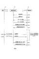
図16は、図1に示した分散システム1において、ソフトウェア無線機3の無線方式を切り替えて無線機を構成するシーケンス(S50)を示すシーケンス図である。 FIG. 16 is a sequence diagram showing a sequence (S50) for configuring the radio by switching the radio system of the software defined
図16に示すように、ステップ500(S500)において、ソフトウェア無線機3が所定の無線方式の通信プログラムを実行中に、ユーザの操作などによる無線方式の切り替えの要求があると、通信制御部10はソフトウェア無線機3に対し、通信諸元設定要求電文4を送信する。
ステップ502(S502)において、ソフトウェア無線機3から通信制御部10に対して、通信諸元設定要求を受信したことを示す応答が送信される(通信諸元設定応答)。As shown in FIG. 16, in step 500 (S500), when the software defined
In step 502 (S502), a response indicating that the communication specification setting request has been received is transmitted from the software defined
ソフトウェア無線機3は、通信諸元設定要求電文4を受信すると、無線方式の切替え時の構築処理(S20)を行う。
なお、ソフトウェア無線機3は、通信制御部10から通信諸元設定要求電文4を受信し、コンポーネントの取得が必要である場合には、インデックスファイル名を通信サーバ2に対して送信し、通信サーバ2からインデックスファイル名に応じてコンポーネントを取得する。
また、ソフトウェア無線機3は、コンポーネントの取得が必要でない場合には、コンポーネントを新たに取得することなく、無線方式を切替える。When the software defined
Note that the software defined
Further, the software defined
ステップ504(S504)において、ソフトウェア無線機3は、S20の処理が終了すると、通信諸元設定完了通知を通信制御部10に対して送信する。
ステップ506(S506)において、通信制御部10からソフトウェア無線機3に対して、通信諸元設定完了通知を受信したことを示す応答が送信される(通信諸元設定完了応答)。In step 504 (S504), when the process of S20 is completed, the software defined
In step 506 (S506), a response indicating that the communication specification setting completion notification has been received is transmitted from the
次に、ソフトウェア無線機3が無線方式を切替える場合にかかる処理時間(試算値)を実施例に基づいて説明する。
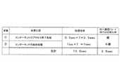
図17は、ソフトウェア無線機3が通信プログラム5の1つであるAM音声LANプログラムを構築して音声通信を実行している場合に、ソフトウェア無線機3がプロセス終了処理および削除処理を実行するためにかかる処理時間を示す図表である。
図17に示すように、ソフトウェア無線機3は、コンポーネント50−1〜50−7が通信アプリケーション作成プログラム52(上位)からプロセス終了指示を受信し、音声データの送受信を禁止し、受信バッファおよび蓄積バッファに溜まっている音声データを出力し、プロセス終了準備完了を上位に通知する処理(プロセス終了処理)に500msecかかる。
また、ソフトウェア無線機3は、起動時の構築処理において作成したコンポーネントの1つ(音声通信コンポーネントなど)を削除し、起動時の構築処理において確保したメモリ領域を開放し、ORB終了処理を行って、プロセスを終了させる処理(削除処理)に1secかかる。Next, a processing time (estimated value) required when the software defined
FIG. 17 shows that when the software defined
As shown in FIG. 17, in the software defined
Also, the software defined
図18は、ソフトウェア無線機3が通信プログラム5の1つであるAM音声アナログプログラムを新たに構築して運用する場合にかかる処理時間を示す図表である。
図18に示すように、ソフトウェア無線機3は、コントロールユニット32がORB環境を初期化し、コンポーネントの1つ(音声通信コンポーネントなど)に対してネーミングサービスオブジェクトを取得し、サーバモジュール群を含む1つのコンポーネントのインスタンスを生成してORBに登録し、クライアントモジュール群を含む1つのコンポーネントのインスタンスを生成し、ネーミングサービスに登録する処理(起動処理)に1secかかる。FIG. 18 is a chart showing the processing time when the software defined
As shown in FIG. 18, in the software defined
また、ソフトウェア無線機3は、音声通信処理を実行するために必要なサーバオブジェクトリファレンスを取得することにより、コンポーネント間を接続する処理(接続処理)に対して1接続当たり1secかかる。 In addition, the software defined
また、ソフトウェア無線機3は、通信諸元設定要求電文4からコンポーネントの1つ(音声通信コンポーネントなど)に対して動作モード情報を取得する処理(動作モードの取得処理)に500msecかかる。 Further, the software defined
また、ソフトウェア無線機3は、音声通信処理を実行するために必要なメモリ領域を確保してメモリ領域を初期化し、自己診断する処理(初期化および自己診断)に500msecかかる。 The software defined
また、ソフトウェア無線機3は、コンポーネントの1つ(音声通信コンポーネントなど)のプロセスの起動通知を通信アプリケーション作成プログラム52(上位)に通知し、通信アプリケーション作成プログラム52からプロセスの準備完了通知を受信して運用を開始する処理(運用開始処理)に1secかかる。 Further, the software defined
分散システム1(図1)においては、例えばAM音声LANプログラムおよびAM音声アナログプログラムは、1つの通信グループに包含される通信系である。
したがって、ソフトウェア無線機3は、AM音声LANプログラムを構築して音声通信を実行している場合に、通信サーバ2からコンポーネントを取得することなく、AM音声アナログプログラムを構築するように無線方式を切替えることができる。In the distributed system 1 (FIG. 1), for example, an AM voice LAN program and an AM voice analog program are communication systems included in one communication group.
Therefore, the software defined
図19,図20は、それぞれ図17,図18に示した各処理を全てのコンポーネントに対して実行した場合にかかる処理時間を示す図表である。
なお、図19,図20に示された処理時間は、AM音声LANプログラムとAM音声アナログプログラムとがそれぞれ7つのコンポーネントから構成され、コンポーネント間の接続数がそれぞれ9であり、各コンポーネントに対する処理に必要な時間が処理ごとに同じであり、かつ、コントロールユニット32(図2)が各処理をシリアルに実行するものとして算出されている。19 and 20 are charts showing processing times required when the processes shown in FIGS. 17 and 18 are executed for all components, respectively.
19 and 20, the AM voice LAN program and the AM voice analog program are each composed of seven components, the number of connections between the components is 9, and the processing for each component is performed. The required time is the same for each process, and the control unit 32 (FIG. 2) is calculated as executing each process serially.
ソフトウェア無線機3(図1,2)は、通信サーバ2からコンポーネントを取得することなく、AM音声LANプログラムによる無線方式からAM音声アナログプログラムによる無線方式に切替えることができるので、図19に示すように、無線方式を切替える場合にコンポーネントの削除処理にかかる7secの処理時間を不要にすることができる。
また、ソフトウェア無線機3は、図20に示すように、無線方式を切替える場合にコンポーネントの起動処理にかかる7secの処理時間を不要にすることができる。As shown in FIG. 19, the software defined radio 3 (FIGS. 1 and 2) can switch from the wireless system based on the AM voice LAN program to the wireless system based on the AM voice analog program without acquiring components from the
Further, as shown in FIG. 20, the software defined
1・・・分散システム1
10・・・通信制御部
100・・・入力装置
102・・・表示装置
12・・・ネットワーク
2・・・通信サーバ
20・・・コンポーネントDB(データベース)
200・・・インデックスファイルDB(データベース)
3・・・ソフトウェア無線機
30・・・基本構成部
302・・・プログラマブルモデムプロセッサ
310・・・対応テーブル
32・・・コントロールユニット
4・・・通信諸元設定要求電文
40・・・本体部
400・・・通信諸元記述部
402・・・通信グループ名
404・・・ダウンロード要フラグ
42・・・ヘッダ部
5・・・通信プログラム
50−1〜50−7・・・コンポーネント
500・・・起動処理モジュール
502・・・動作モード設定サーバモジュール
504・・・コンポーネント初期化サーバモジュール
506・・・自己診断サーバモジュール
508・・・コンポーネント接続サーバモジュール
510・・・運用開始サーバモジュール
512・・・プロセス終了サーバモジュール
514・・・コンポーネント削除サーバモジュール
516・・・クライアントモジュール群
518・・・サーバモジュール群
52・・・通信アプリケーション作成プログラム
520・・・アプリケーション作成クライアントモジュール1 ... Distributed
DESCRIPTION OF
200 ... index file DB (database)
DESCRIPTION OF
Claims (1)
Translated fromJapanese前記クライアントは、
前記制御部が出力した制御情報に応じて、前記サーバからオブジェクトを取得するオブジェクト取得手段と、
前記制御部が出力した制御情報に応じて、オブジェクトを組合わせてアプリケーションを構築するアプリケーション構築手段と
を有する
分散システム。A server that stores a plurality of objects; a client for the server; and a control unit that outputs control information including object combination information, object acquisition necessity and an instruction to change an application to the client. A distributed system,
The client
Object acquisition means for acquiring an object from the server in accordance with the control information output by the control unit;
A distributed system comprising: an application construction unit that constructs an application by combining objects according to control information output by the control unit.
Priority Applications (1)
| Application Number | Priority Date | Filing Date | Title |
|---|---|---|---|
| JP2005157598AJP2006331307A (en) | 2005-05-30 | 2005-05-30 | Distributed system |
Applications Claiming Priority (1)
| Application Number | Priority Date | Filing Date | Title |
|---|---|---|---|
| JP2005157598AJP2006331307A (en) | 2005-05-30 | 2005-05-30 | Distributed system |
Publications (1)
| Publication Number | Publication Date |
|---|---|
| JP2006331307Atrue JP2006331307A (en) | 2006-12-07 |
Family
ID=37552907
Family Applications (1)
| Application Number | Title | Priority Date | Filing Date |
|---|---|---|---|
| JP2005157598APendingJP2006331307A (en) | 2005-05-30 | 2005-05-30 | Distributed system |
Country Status (1)
| Country | Link |
|---|---|
| JP (1) | JP2006331307A (en) |
Cited By (7)
| Publication number | Priority date | Publication date | Assignee | Title |
|---|---|---|---|---|
| JP2010045702A (en)* | 2008-08-18 | 2010-02-25 | Hitachi Kokusai Electric Inc | Software radio machine system |
| JP2011134095A (en)* | 2009-12-24 | 2011-07-07 | Hitachi Kokusai Electric Inc | Software radio device |
| JP2012527206A (en)* | 2009-05-17 | 2012-11-01 | クアルコム,インコーポレイテッド | Method and apparatus for programming a mobile device having multiple service accounts |
| US8620235B2 (en) | 2008-05-23 | 2013-12-31 | Qualcomm Incorporated | Thermal management for data modules |
| US8756256B2 (en) | 2010-05-26 | 2014-06-17 | Qualcomm Incorporated | Method and systems for the management of non volatile items and provisioning files for a communication device with multiple service accounts |
| JP2017220003A (en)* | 2016-06-07 | 2017-12-14 | 日本電気株式会社 | Radio device, communication method, and communication program |
| JP2024508452A (en)* | 2021-02-26 | 2024-02-27 | スラック テクノロジーズ, エルエルシー | Hosting event-based applications |
Citations (7)
| Publication number | Priority date | Publication date | Assignee | Title |
|---|---|---|---|---|
| JP2001043087A (en)* | 1999-08-02 | 2001-02-16 | Nippon Telegr & Teleph Corp <Ntt> | Software change method for wireless communication terminal and wireless communication terminal |
| JP2002304301A (en)* | 2001-01-18 | 2002-10-18 | Sony Service Center Europ Nv | Downloading device and downloading method |
| JP2002335186A (en)* | 2001-01-25 | 2002-11-22 | Toshiba Corp | Wireless communication device compatible with multiple wireless communication systems |
| JP2002540529A (en)* | 1999-03-29 | 2002-11-26 | クォーク・メディア・ハウス・ソシエテ・ア・レスポンサビリテ・リミテ | Dynamic application system for distributed computer environment |
| JP2003173260A (en)* | 2001-12-06 | 2003-06-20 | Mitsubishi Electric Corp | Remote program update system |
| JP2004032478A (en)* | 2002-06-27 | 2004-01-29 | Mitsubishi Electric Corp | Radio device control system |
| JP2004187184A (en)* | 2002-12-06 | 2004-07-02 | Hitachi Kokusai Electric Inc | transceiver |
- 2005
- 2005-05-30JPJP2005157598Apatent/JP2006331307A/enactivePending
Patent Citations (7)
| Publication number | Priority date | Publication date | Assignee | Title |
|---|---|---|---|---|
| JP2002540529A (en)* | 1999-03-29 | 2002-11-26 | クォーク・メディア・ハウス・ソシエテ・ア・レスポンサビリテ・リミテ | Dynamic application system for distributed computer environment |
| JP2001043087A (en)* | 1999-08-02 | 2001-02-16 | Nippon Telegr & Teleph Corp <Ntt> | Software change method for wireless communication terminal and wireless communication terminal |
| JP2002304301A (en)* | 2001-01-18 | 2002-10-18 | Sony Service Center Europ Nv | Downloading device and downloading method |
| JP2002335186A (en)* | 2001-01-25 | 2002-11-22 | Toshiba Corp | Wireless communication device compatible with multiple wireless communication systems |
| JP2003173260A (en)* | 2001-12-06 | 2003-06-20 | Mitsubishi Electric Corp | Remote program update system |
| JP2004032478A (en)* | 2002-06-27 | 2004-01-29 | Mitsubishi Electric Corp | Radio device control system |
| JP2004187184A (en)* | 2002-12-06 | 2004-07-02 | Hitachi Kokusai Electric Inc | transceiver |
Cited By (7)
| Publication number | Priority date | Publication date | Assignee | Title |
|---|---|---|---|---|
| US8620235B2 (en) | 2008-05-23 | 2013-12-31 | Qualcomm Incorporated | Thermal management for data modules |
| JP2010045702A (en)* | 2008-08-18 | 2010-02-25 | Hitachi Kokusai Electric Inc | Software radio machine system |
| JP2012527206A (en)* | 2009-05-17 | 2012-11-01 | クアルコム,インコーポレイテッド | Method and apparatus for programming a mobile device having multiple service accounts |
| JP2011134095A (en)* | 2009-12-24 | 2011-07-07 | Hitachi Kokusai Electric Inc | Software radio device |
| US8756256B2 (en) | 2010-05-26 | 2014-06-17 | Qualcomm Incorporated | Method and systems for the management of non volatile items and provisioning files for a communication device with multiple service accounts |
| JP2017220003A (en)* | 2016-06-07 | 2017-12-14 | 日本電気株式会社 | Radio device, communication method, and communication program |
| JP2024508452A (en)* | 2021-02-26 | 2024-02-27 | スラック テクノロジーズ, エルエルシー | Hosting event-based applications |
Similar Documents
| Publication | Publication Date | Title |
|---|---|---|
| CN115242565B (en) | System architecture, communication method and equipment for realizing DDS communication based on AUTOSAR | |
| US20030189913A1 (en) | Methods of transmitting and executing contents of program for hand-held terminal | |
| CN112600856A (en) | Equipment authorization method and device, storage medium and electronic device | |
| US20240192908A1 (en) | Server, musical instrument, server communication method, and communication method | |
| JP3894194B2 (en) | Reconfiguration of programmable components of electronic units | |
| JP2004538688A (en) | Communication protocol conversion apparatus and method | |
| KR20120137756A (en) | Method and apparatus for merging applications in portable terminal | |
| JP2006331307A (en) | Distributed system | |
| CN114253890A (en) | Communication module, external interface configuration method and device thereof, and storage medium | |
| KR100676905B1 (en) | Mobile communication terminal with integrated remote controller function | |
| CN102243576A (en) | Image forming apparatus and image forming method | |
| JP2011138391A (en) | Information processing apparatus and method for controlling the same | |
| RU2297732C2 (en) | Method for executing a client program by radio communication block | |
| JP2006309533A (en) | Distributed processing program | |
| CN103237050A (en) | Method and system for intelligent voice interaction | |
| JP5032930B2 (en) | Communications system | |
| EP1515503A1 (en) | Electronic mail distribution method, communication terminal, and server device | |
| JP4648853B2 (en) | Wireless communication system | |
| CN116437450A (en) | Beam resource allocation method and device, electronic equipment and storage medium | |
| JP2004362090A (en) | Software distribution system for mobile terminals | |
| JP2003015911A (en) | Processing completion notification system and processing completion notification method | |
| CN111949133B (en) | Haptic feedback method, related device and computer-readable storage medium | |
| JP2011035811A (en) | Storage system, access management apparatus, data transfer method and program | |
| KR100932208B1 (en) | Software-Defined Wireless Device Based on Software Communication Structure and Waveform Execution Method in the Device | |
| JP4063232B2 (en) | Acoustic signal processing system |
Legal Events
| Date | Code | Title | Description |
|---|---|---|---|
| A621 | Written request for application examination | Free format text:JAPANESE INTERMEDIATE CODE: A621 Effective date:20080331 | |
| A977 | Report on retrieval | Free format text:JAPANESE INTERMEDIATE CODE: A971007 Effective date:20110328 | |
| A131 | Notification of reasons for refusal | Free format text:JAPANESE INTERMEDIATE CODE: A131 Effective date:20110715 | |
| A521 | Written amendment | Free format text:JAPANESE INTERMEDIATE CODE: A523 Effective date:20110912 | |
| A131 | Notification of reasons for refusal | Free format text:JAPANESE INTERMEDIATE CODE: A131 Effective date:20111011 | |
| A02 | Decision of refusal | Free format text:JAPANESE INTERMEDIATE CODE: A02 Effective date:20120217 |