JP2006329904A - Liquid transport device and analysis system - Google Patents
Liquid transport device and analysis systemDownload PDFInfo
- Publication number
- JP2006329904A JP2006329904AJP2005156575AJP2005156575AJP2006329904AJP 2006329904 AJP2006329904 AJP 2006329904AJP 2005156575 AJP2005156575 AJP 2005156575AJP 2005156575 AJP2005156575 AJP 2005156575AJP 2006329904 AJP2006329904 AJP 2006329904A
- Authority
- JP
- Japan
- Prior art keywords
- region
- liquid
- transport device
- oil
- liquid transport
- Prior art date
- Legal status (The legal status is an assumption and is not a legal conclusion. Google has not performed a legal analysis and makes no representation as to the accuracy of the status listed.)
- Pending
Links
Images


Landscapes
- Investigating Or Analysing Materials By Optical Means (AREA)
- Physical Or Chemical Processes And Apparatus (AREA)
- Sampling And Sample Adjustment (AREA)
- Automatic Analysis And Handling Materials Therefor (AREA)
Abstract
Description
Translated fromJapanese本発明は基板上で液体を操作するシステムに関する。特に多数の液体を搬送する分析または反応システムに関する。 The present invention relates to a system for manipulating liquid on a substrate. In particular, it relates to analysis or reaction systems that carry a large number of liquids.
試料中に含まれる成分量を検出する分析装置として、ハロゲンランプ等からの白色光を試料と試薬との混合液である反応液に照射し、反応液を透過してきた光を回折格子で分光して必要な波長成分を取り出し、その吸光度を割り出すことで目的の成分量を測定する分光分析装置が広く用いられている。あるいは、白色光を回折格子で分光した後、反応液に照射する場合もある。これらの分析装置においては、従来、プラスチックやガラスの反応容器内に試料と試薬とを分注し、これらを混合して反応液として光を照射し、成分量を測定していた。 As an analytical device that detects the amount of components contained in a sample, white light from a halogen lamp or the like is irradiated onto the reaction solution, which is a mixture of the sample and reagent, and the light transmitted through the reaction solution is dispersed with a diffraction grating. Thus, a spectroscopic analyzer for measuring a target component amount by taking out a necessary wavelength component and determining its absorbance is widely used. Alternatively, the reaction solution may be irradiated after white light is separated by a diffraction grating. Conventionally, in these analyzers, a sample and a reagent are dispensed into a plastic or glass reaction vessel, mixed, and irradiated with light as a reaction solution to measure the amount of components.
しかし近年、試薬コストの削減や、環境への負荷低減のため、分析に用いる反応液の微少量化が求められており、従来方式での反応液微少量化では液の取り扱いが困難になり、また分注、混合時に発生する気泡等により正確な測定ができなくなるという問題があった。このため、微少量の液体を的確に操作する技術が求められていた。 However, in recent years, in order to reduce reagent costs and reduce the burden on the environment, it has been required to reduce the amount of reaction solution used for analysis. Note: There was a problem that accurate measurement could not be performed due to bubbles generated during mixing. For this reason, a technique for accurately manipulating a minute amount of liquid has been demanded.
微少量の液体を操作する一つの方法として、平面基板に形成された電極上の液体を電気的な制御により搬送する方法がある。この代表的な一つの方法は、複数の電極を形成した二つの対向する基板間に、搬送する液体を粒状の液体にして挟みこみ、二つの対向する基板間の表面に沿って配置された電極に電圧を印加することで、液体を搬送する(例えば非特許文献1、非特許文献2)。二つの対向する基板で構成されたものを液体搬送デバイスと称する。この方法では、通常、液体を搬送させる液体搬送路に沿って、片方の基板上に多数の電極が形成され、もう一方の基板上にグランドに接続された一つの電極を備える。粒状の液体下部の電極の一つに電圧を印加すると、エレクトロウェティング現象(例えば非特許文献3)により、電圧を印加した電極の上の濡れ性が良くなり、その電圧を印加した電極に載るようにその粒状の液体が移動する。これを繰り返すことで液体を搬送する。 As one method for manipulating a minute amount of liquid, there is a method of conveying liquid on an electrode formed on a flat substrate by electrical control. One typical method is to sandwich a liquid to be conveyed between two opposing substrates on which a plurality of electrodes are formed, and to arrange the electrodes along the surface between the two opposing substrates. By applying a voltage to the liquid, the liquid is transported (for example,
また、複数に分岐した電極列を用いて液体を分岐に振り分けたり、複数の溝が合流する位置で液体を融合させることも報告されている(例えば特許文献1)。また、一つの粒状の液体を分割することも報告されている(例えば特許文献2)。また試料を搬送し、液体搬送デバイス内部で計測を行うようなシステムも報告されている(非特許文献4)。このような、液体を搬送する液体搬送デバイスの利点は、周囲が壁に囲まれた容器に比べ、基板を利用するため気泡の影響を受けにくいことなどが挙げられる。
代表的な液体搬送デバイスの内部は、非特許文献1記載の通り、オイルで満たされているか、非特許文献2記載の通り、液体周囲のみオイルで取り囲まれている。In addition, it has been reported that the liquid is divided into branches using a plurality of electrode arrays branched, or the liquid is fused at a position where a plurality of grooves join (for example, Patent Document 1). It has also been reported that one granular liquid is divided (for example, Patent Document 2). In addition, a system that transports a sample and performs measurement inside the liquid transport device has been reported (Non-patent Document 4). Advantages of such a liquid transport device for transporting liquid include that it is less susceptible to bubbles due to the use of a substrate compared to a container surrounded by a wall.
The interior of a typical liquid transport device is filled with oil as described in
液体が搬送される際、液体が搬送されることによってオイルが流動するため、デバイス表面と液体との間に多量にオイルが入りこむことがある。液体搬送デバイスの一部に測定部を設け、測定部において透過光や、発光、及びインピーダンスなどの電気的な信号を計測する場合、測定する領域に多量のオイルが入りこむと、散乱により光量が減少することや、光が透過する試料の量が変化することで、測定の再現性への影響が生じる。また液体が搬送されている際にオイルが大きく流動すると、搬送する液体が、搬送を制御する電極上から離れ、搬送できなくなってしまうという問題がある。本発明はこれらの問題を解決する液体搬送デバイスを提供することを目的としている。 When the liquid is transported, the oil flows due to the transport of the liquid, so that a large amount of oil may enter between the device surface and the liquid. When a measurement unit is provided in a part of the liquid transfer device and electrical signals such as transmitted light, light emission, and impedance are measured in the measurement unit, the amount of light decreases due to scattering if a large amount of oil enters the measurement area. And the change in the amount of the sample through which light is transmitted affects the reproducibility of the measurement. Further, if the oil flows greatly while the liquid is being transported, there is a problem that the transported liquid is separated from the electrode for controlling the transport and cannot be transported. An object of the present invention is to provide a liquid transport device that solves these problems.
液体搬送デバイスの表面に、オイルに対して親和性の異なる二つの領域を設けることで、オイルの位置を制御し、液体と液体搬送デバイス表面との内にオイルが多量に入りこむことや、オイルが大きく流動することにより搬送する液体が制御できない位置に移動することを防止する。具体的には、例えば親油部と撥油部という2つの領域を設ける。これにより測定の再現性を向上させ、また確実に液体を搬送できる。 By providing two areas with different affinity for oil on the surface of the liquid transfer device, the position of the oil is controlled, so that a large amount of oil enters the liquid and the surface of the liquid transfer device, It is prevented that the liquid to be conveyed moves to an uncontrollable position by flowing largely. Specifically, for example, two regions, a lipophilic portion and an oil repellent portion, are provided. As a result, the reproducibility of the measurement can be improved and the liquid can be reliably conveyed.
液体搬送デバイスの一例としては、第1の基礎基板と、前記第1の基礎基板上に設けられた複数の第1電極と、第1の液体及び第2の液体を導入するための導入口と、前記第1の液体及び前記第2の液体を排出するための排出口と、前記第1の液体についての測定を行なうための測定部と、前記複数の第1電極の少なくとも一部に電圧を印加する導電手段と、前記測定部に設けられた第1の領域と、前記第1の領域の近傍に設けられ、前記第1の領域よりも前記第2の液体に対する親和性の高い第2の領域とを有することを特徴とする。 As an example of the liquid transport device, a first basic substrate, a plurality of first electrodes provided on the first basic substrate, and an inlet for introducing the first liquid and the second liquid, A discharge port for discharging the first liquid and the second liquid, a measurement unit for measuring the first liquid, and a voltage applied to at least some of the plurality of first electrodes. A conductive means to be applied; a first region provided in the measurement unit; and a second region that is provided in the vicinity of the first region and has a higher affinity for the second liquid than the first region. And a region.
また、分析システムの一例としては、第1の液体を供給する手段と、第2の液体を供給する手段とを具備する第1のユニットと、前記第1の液体を供給する手段から吐出された前記第1の液体を導入する導入部と、前記第1の液体を導出する排出口と、複数の第1電極を備えてかつ前記導入部と前記排出口とをつなぐ液体搬送路と、前記液体搬送路の少なくとも一部に設けられた測定部と、前記複数の第1電極の少なくとも一部に電圧を印加する電圧印加手段を具備する第2のユニットと、前記測定部で検出するための検出系を具備する第3のユニットと、前記排出口から液体を排出するための第4のユニットとを有し、前記第2のユニットは、前記測定部に設けられた第1の領域と、前記第1の領域の近傍に設けられ、前記第1の領域よりも前記第2の液体に対する親和性の高い第2の領域とを有し、前記電圧印加手段は、前記第1の液体を前記液体搬送路に沿って移動させるように、前記複数の第1電極の少なくとも一部に電圧を印加することを特徴とする。 In addition, as an example of the analysis system, the first unit including a first liquid supplying unit and a second liquid supplying unit, and the first liquid supplying unit are discharged from the first unit. An introduction section for introducing the first liquid; a discharge opening for discharging the first liquid; a liquid transport path including a plurality of first electrodes and connecting the introduction section and the discharge opening; and the liquid A measurement unit provided in at least a part of the transport path; a second unit including a voltage application unit that applies a voltage to at least a part of the plurality of first electrodes; and detection for detection by the measurement unit A third unit having a system and a fourth unit for discharging liquid from the discharge port, wherein the second unit includes a first region provided in the measurement unit, Provided in the vicinity of the first region, and more than the first region A second region having a high affinity for the second liquid, and the voltage applying means includes at least one of the plurality of first electrodes so as to move the first liquid along the liquid transport path. A voltage is applied to a part thereof.
本発明のようにデバイス表面のオイルの親和性を制御することにより、測定部においてオイルが必要以上に入りこみ、測定を妨げるのを防止することができる。これにより測定の再現性がよくなる。また液体を搬送する際にオイルが流動することにより、液体が制御電極上から離れてしまうのを防止することができる。これにより確実に液体を搬送することができる。 By controlling the affinity of the oil on the surface of the device as in the present invention, it is possible to prevent the oil from entering more than necessary in the measuring section and preventing the measurement from being disturbed. This improves the reproducibility of the measurement. In addition, when the liquid is transported, the oil can be prevented from moving away from the control electrode due to the oil flowing. Thereby, a liquid can be conveyed reliably.
本実施例では、液体搬送デバイス内に水溶性の試料をオイルとともに導入し、オイルで試料をとり囲みながら液体搬送デバイス内を搬送し、測定部において試料の吸光度を測定した後、試料とオイルを排出する分析システムを示す。
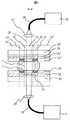
図1に分析システムの構成を示す。分析システムは液体搬送デバイス10と、試料1及びオイル2を液体搬送デバイス10に導入するための導入ユニット11と、試料1の内部の成分を測定するための検出ユニット12と、試料1及びオイル2を液体搬送デバイス10から排出するための排出ユニット13から構成される。導入ユニット11には試料1が試料槽に収容等されて、またオイル2がオイル槽に収容等されて各々配置され、それぞれ試料プローブ4、オイルプローブ5により導入口6から液体搬送デバイス10内に導入することができる。検出ユニット12は、液体搬送デバイス10に液体が導入され排出されるまでに通過する液体搬送路の少なくとも一部に設置された測定部に隣接して設置される。排出ユニット13にはシッパー7と廃液タンク9が配置され、排出口8に搬送された液体をシッパー7により液体搬送デバイス10内から廃液タンク9へ排出できる。In this example, a water-soluble sample is introduced into the liquid transport device together with oil, transported through the liquid transport device while surrounding the sample with oil, and after measuring the absorbance of the sample in the measurement unit, the sample and oil are The analysis system to be discharged is shown.
Figure 1 shows the configuration of the analysis system. The analysis system includes a
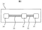
図2に、液体搬送デバイス10内において、導入、搬送、測定、排出の各操作を行う各部の配置図を示す。液体搬送デバイス10は、導入口6を備えた導入部14、試料1の内部成分を測定するための測定部16、排出口8を備えた排出部17、各部を結ぶ液体搬送路15で構成される。導入部14、液体搬送路15、測定部16、排出部17の各々の少なくとも一部には液体を搬送するための制御電極が配置されており、制御電極への印加電圧の制御により、試料1が搬送される。 FIG. 2 shows a layout of each part that performs each operation of introduction, transport, measurement, and discharge in the
図3に本実施例で用いた液体搬送路15の搬送方向における断面構成図を示す。液体搬送デバイス10は下側基板18及び上側基板19から構成されている。下側基板18では絶縁性の基礎基板20の上表面に試料1の搬送方向に沿って多数の制御電極21が配置され、さらにその表面は絶縁膜22で覆われている。上側基板19では絶縁性の基礎基板20’の下表面に1つの共通電極24が配置され、さらにその表面は絶縁膜22’で覆われている。さらにそれぞれの絶縁膜22、22’の表面には試料1が搬送しやすいよう、撥水性を付与するため撥水膜23、23'が塗布されている。これらの上下基板間に、搬送する試料1を配置し、その周囲をオイル2で取り囲む。すなわち、搬送する試料1の液滴がオイル2に内包され、試料1の液滴とオイル2の複合体となる。ここで内包とは、一のオイルが一の液体(液滴)の外表面を実質的に覆うように位置することをいう。オイル2の周囲には空気3が存在する。本実施例では絶縁性の基礎基板20、20’に石英を、制御電極21及び共通電極24にITO(Indium-Tin Oxide)を、絶縁膜23、23’にCVD(Chemical Vapor Deposition)で成膜したSiO2を用い、撥水膜としてデュポン社製TeflonAFを用いた。ITOの厚みは70nmとし、CVDで成膜した絶縁膜22、22’の厚みは200nmとした。また下側基板18と上側基板19の間の距離は0.5mmとした。また試料1として水溶液を、オイル2としてシリコーンオイルを用い、液量はそれぞれ5μLとした。下側基板18と上側基板19の間にオイル2で取り囲まれた試料1を設置することにより、オイルの蒸発防止効果が高まり、また、オイルが重力で引かれて液体から分離することを回避することができる。FIG. 3 shows a cross-sectional configuration diagram in the transport direction of the
図4に本実施例で用いた液体搬送デバイスを上部から見た場合の、透視図を示す。略化してわかりやすくするため、試料1、オイル2、制御電極21のみを図示し、電圧を印加している制御電極21をハッチングで示す。また制御電極21上部に位置する共通電極24はアースに接続し、電圧は共通電極24と一部の制御電極21との間に印加する。また本願では電圧を印加していない制御電極21はどこにも接続されていないフロートの状態とし、印加電圧を切る場合は、電圧印加を停止してから制御電極21を一旦アースに接続した後、制御電極21をフロートの状態にする。上部からみて試料1と制御電極が重なりを持っているとき、試料1と重なる領域を持った制御電極21に電圧を印加すると、電圧を印加した制御電極21の上に載るように試料1が移動する。はじめに、図4(a)のように、液体搬送路に沿って制御電極21が複数配置され、制御電極21b近傍にオイル2に囲まれた試料1が存在するとき、制御電極21bに電圧を印加すると、図4(b)のように試料1が制御電極21bに載るように移動する。次に制御電極21cに電圧を印加し、制御電極21bの印加電圧を切ると、試料1は図4(c)のようにオイル2と空気3との気液界面と接した後、オイル2と空気3との気液界面を押しながら、図4(d)のようにオイル2と供に移動して、制御電極21cに載るように移動する。 FIG. 4 shows a perspective view of the liquid transport device used in the present embodiment as viewed from above. For the sake of brevity and clarity, only the
さらに制御電極21dに電圧を印加し、制御電極21cの印加電圧を切ると、試料1は図4(e)のようにオイル2と空気3との気液界面を押しながら、図4(f)のようにオイル2と供に移動して制御電極21dに載るように移動する。これを繰り返すことで試料1をオイル2に囲まれたまま搬送することが可能である。また、オイル2で囲まれた液体1は制御電極の配列に沿って移動することとなる。本実施例では試料1として水溶液を用いたが、純水、緩衝液などでもよい。また血液や、DNAが含まれる溶液でもよい。また試料1にラテックス粒子、細胞、磁性ビーズなどが含まれていてもよい。またオイル2としてシリコーンオイルを用いたが、搬送する液体に対して不混和性の液体であればよい。また絶縁性の基礎基板20、20’として石英を用いたが、Si等の導電性基板上に酸化膜等の絶縁膜を成膜した基板や、樹脂性の基板でもよい。また絶縁膜22、22’にはCVD(Chemical Vapor deposition)にて成膜したSiO2を用いたが、ポリシラザンや、SiN、Paryleneなどの絶縁膜でもよい。また本実施例では絶縁膜22、22’上に撥水膜23、23’を成膜したが、これらの絶縁膜や撥水膜といった層状部材は,1つでもよい。例えば,撥水膜23、23’の代わりに撥水性絶縁膜を成膜するか、もしくは、絶縁膜22、22’の代わりに絶縁性撥水膜を成膜してもよい。When the voltage is further applied to the control electrode 21d and the voltage applied to the control electrode 21c is turned off, the
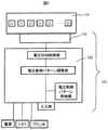
図5に液体搬送デバイス10内で液体1を操作するための電圧制御手段101の構成を示す。本制御手段は、図1に示した分析システムに設けられ、制御用コンピュータ102と、制御用コンピュータ102で制御された印加電圧を液体搬送デバイス10の所定の電極へ印加するための連絡部103とを有する。制御用コンピュータにはCRT、プリンタ、電源が接続される。制御用コンピュータには、分析対象や液体搬送方法について適宜条件を入力するための入力部、各種液体搬送方法に応じた電圧制御パターンを記憶する電圧制御パターン格納部、入力部から入力された情報に基づいて分析対象に応じた電圧制御パターンの組合せを定める電圧制御パターン調整部、電圧制御パターン調整部で定めた電圧制御パターンの組合せに応じて電圧を液体搬送デバイス10に印加する電圧印加制御部を備える。連絡部103は制御電極21に接続され、液体1を制御する際は入力部から入力された情報に従い、電圧印加制御部の制御を受けた電圧が連絡部103を介して所定の電極に印加される。 FIG. 5 shows the configuration of the voltage control means 101 for operating the
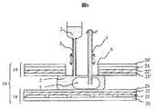
図6に導入部14の断面構成図を示す。上側基板19に導入口6が配置され、容器に収容されたオイル2を導入するためのオイルプローブ5と容器に収容された試料1を導入するための試料プローブ4が導入口中をそれぞれ上下移動可能なように設置されている。始めにオイルプローブ5より5μLのオイル2を液体搬送デバイス内に導入した後、試料プローブ4より、オイル2の内部に試料1を5μL導入する。その後、試料プローブ4、オイルプローブ5は上方向に移動し、試料1とオイル2を液体搬送デバイス10内に脱離する。これにより、オイル2中に確実に試料1を配置することができる。このときオイルプローブよりも試料プローブが先に上方向に移動することで、試料プローブ4先端をオイル2と空気3との界面を通過させる。これにより、試料プローブ4先端に残ることなく確実にオイル中に試料を導入できる。導入後、制御電圧に電圧を印加することで、試料1をオイル2とともに搬送する。液体搬送デバイス10内で試料1をオイル2とともに搬送する。 FIG. 6 shows a cross-sectional configuration diagram of the
図7に排出部17の断面構成図を示す。排出部17では上側基板19に排出口8が配置されており、排出部17に搬送された試料1とオイル2は、排出口8より、排出ユニット13のシッパー7に吸引され、廃液タンク9に排出される。廃液タンク9内では集まったオイル2と試料1とが比重の違いにより分離するため、多数の試料及びそれを囲むオイルが排出されても、オイルや試料の処理が容易である。 FIG. 7 shows a cross-sectional configuration diagram of the
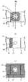
図8に測定部16を上部から見た場合の構成図を示す。簡単のため、制御電極の位置及び光が照射される領域、当該領域を含む第1の領域、及び、その周辺に設けられかつ第1の領域よりもオイルとの親和性の高い第2の領域を図に示す。測定部16では、図8(a)のように1つの測定部16に位置する制御電極21’中に光が照射される領域34と、領域34を含む領域として第1の領域32が設けられ、光は主として第1の領域32の中の領域34を透過する。本実施例では光が照射された領域は領域34と一致するが、光が照射された領域は第1の領域32と一致してもよい。また、本実施例では領域34は光を検出する領域と一致している。第1の領域32周囲には第1の領域32と比較してオイルとの親和性の高い第2の領域33が設けられる。第2の領域のさらに外側は第1の領域と同様の性質を有する領域32’が設けられる。領域34は制御電極の周辺部における光の散乱を避けるため,1つの制御電極に含まれるように位置する。 FIG. 8 shows a configuration diagram when the
ここで、第1の領域は溌油性を有するように構成してもよい。このとき、第1の領域に入り込んだオイルをより確実に第1の領域から第2の領域へ排除することができる。この溌油性は、液体搬送デバイス表面の撥水膜にフルオロカーボン系の撥水膜を用いることで実現できる。オイルとの親和性が高いとは、オイルの表面に対する接触角がより小さいということである。第1の領域と第2の領域にまたがって存在するオイルは、接触角が小さくなる表面を備えた領域の方に移動する。すなわちオイルは第1の領域よりも表面との接触角の小さい第2の領域の上に移動する。本実施例では光が透過する領域34を含む第1の領域32を取り囲むように第2の領域33を設けたが、図8(b)のように第2の領域は第1の領域32の近傍に位置すればよく、必ずしも周囲を囲まなくともよい。図8(b)のように、第2の領域を第1の領域を内包しない形状として構成することもできる。この場合には、第1の領域と第2の領域との設計がより簡便となる。 Here, the first region may be configured so as to have oil repellency. At this time, the oil that has entered the first region can be more reliably removed from the first region to the second region. This oil-repellent property can be realized by using a fluorocarbon water-repellent film as the water-repellent film on the surface of the liquid transport device. High affinity with oil means that the contact angle with the oil surface is smaller. The oil existing across the first region and the second region moves toward the region having a surface with a small contact angle. In other words, the oil moves onto the second region having a smaller contact angle with the surface than the first region. In the present embodiment, the
その一方、図8(b)のように第1の領域の周囲を取り囲む様に第2の領域が設けられてない場合は、オイルが第2の領域上に多く移動する際に影響を受けることも考えられる。この点につき、図8(a)のように周囲を囲んだ場合は、オイルが第2の領域上に多く移動する際にも、オイル中の試料1は光が透過する第1の領域内の概略中心に合わせて位置を制御することができ、確実に試料に光を照射できる。また第2の領域は測定する試料1の周囲のオイルを確実に捉えるため、第1の領域近傍に位置する必要がある。そのため,第1の領域を含む1つの制御電極21’と第2の領域とが重なりを持つように配置されるのが望ましい。また第1の領域は、光が照射される領域を含むものとし、第2の領域は当該光が照射される領域を含まないもの、もしくは測定部を通過した光を検出する集光レンズの集光範囲が含まれないものとすることもできる。集光レンズの集光範囲が含まれない場合には、散乱などによりオイルを捕捉している第2の領域を通過した光が、検出ユニットで検出される光に含まれず、オイルが多く入り込まない領域である光が照射される領域(もしくは第1の領域)を通過した光のみを検出することができ、測定の再現性を高めることができる。このように、領域34を第1の領域32内に配置し、その周囲にオイルと親和性の高い第2の領域33を設けることで、オイルは第1の領域32よりも第2の領域33上に存在しやすくなり、第1の領域32にオイルが必要以上に入り込むのを防ぐことができる。 On the other hand, if the second region is not provided so as to surround the first region as shown in FIG. 8 (b), it is affected when oil moves a lot on the second region. Is also possible. In this regard, when the periphery is surrounded as shown in FIG. 8 (a), even when the oil moves a lot on the second region, the
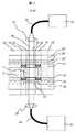
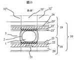
次に、測定部16の搬送方向と垂直な方向(A-A')の断面構成図を図9に、検出ユニット12とともに示す。検出ユニット12ではハロゲンランプ25からの光28を照射光ファイバ26で導き、照射レンズ27により測定部16に照射し、透過光を集光レンズ29で集光光ファイバ30に集光し、分光検出器31で必要な波長に光を分光し検出する。本実施例では600nmの吸光度を測定することで、水溶液の濁度測定を行った。デバイス表面は、第1の領域32(及び適宜デバイス全体について)は撥水性かつ撥油性の撥水膜を用い、第2の領域では撥水性かつ親油性の撥水膜を用いる。本実施例ではオイルにシリコーンオイルを用いており、第1の領域32及び液体搬送デバイス全体の撥水膜23、23'の材料はフッ素系撥水膜を用いている。例えば、TeflonAF(登録商標)を用いることができる。そこで第2の領域33の撥水膜23、23'の材料はフッ素系撥水膜よりもシリコーンオイルに対して親和性の高いシリコーン系撥水膜を用いた。これによりオイルは第1の領域32よりも第2の領域33上に存在しやすくなり、第1の領域にオイルが必要以上に入り込むのを防ぐことができる。このとき第2の領域33を第1の領域32近傍に位置することで、オイルが必要以上に第1の領域32に入りこんで測定を阻害することがなくなり、測定の再現性の向上に寄与する。本発明の構成は、血清の濁度測定や、血清を液体搬送デバイス内で試薬と混合し、吸光度を測定することで血液内部の成分を測定することへの応用も可能である。また発光、蛍光発光の計測や、インピーダンスなどの電気的な信号を用いた計測においても、測定部にオイルが必要以上に入りこむと再現性が悪くなるが、本発明の構成により、再現性が向上する。 Next, a cross-sectional configuration diagram in a direction (AA ′) perpendicular to the conveyance direction of the
また、本実施例では二枚の基板間に試料を挟み込み搬送したが、図10のように上側基板19を設けず、下側基板18のみの構成でも搬送可能である。この場合は下側基板18上に共通電極24を配置する。測定部の構成を図11に示す。この場合においても第2の領域33を第1の領域の周囲もしくは近傍に設けることにより、オイルが第1の領域に多量に入り込むことを防止し、測定の再現性が向上する。 In this embodiment, the sample is sandwiched and transported between the two substrates. However, the
また本実施例では分画されたオイルを用いた液体搬送デバイスであるが、オイルで満たされた液体搬送デバイスにおいても適用ができる。この場合の測定部の構成を図12に示す。この場合には、特に試料の液滴の内部にオイルが偶発的に入り込んでしまった場合等においても、オイルは第1の領域よりも第2の領域に存在しやすく、光28が照射される領域にオイルが入りこまず、測定部においてオイルの位置を制御することができ、測定の再現性を高めることができる。 In this embodiment, the liquid transport device uses fractionated oil, but the present invention can also be applied to a liquid transport device filled with oil. FIG. 12 shows the configuration of the measurement unit in this case. In this case, the oil is more likely to be present in the second region than in the first region, particularly when the oil accidentally enters the sample droplet, and the light 28 is irradiated. The oil does not enter the region, and the position of the oil can be controlled in the measurement unit, so that the reproducibility of the measurement can be improved.
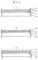
本実施例では、分析システム全体は実施例1と基本的に同じ構成であるが、第2の領域33において撥水膜23及び23'表面に物理的に凸凹の状態とすることにより、オイルとの親和性を高めた。撥水膜の材料はデバイス全体で同じであり、フッ素系撥水膜等を用いることができる。例えば、TeflonAF(登録商標)を用いることができる。図13に例として下側基板18における第1の領域32と第2の領域33の表面構造の違いを示す。第1の領域では表面は図13(a)に示すようにほぼ平らな面であるが、第2の領域では図13(b)に示すように、絶縁膜22をウェットエッチングまたは、ドライエッチング、CVD、機械加工などの種々の加工、成型法により凸凹形状とし、その上に成膜した撥水膜23、23'に凸凹形状を作り出す。これらの凸凹形状はその凸凹の高さ方向の長さが数ナノメートルから数百マイクロメートルのオーダーであり、搬送する試料全体の大きさに対して十分小さければよい。 In the present embodiment, the entire analysis system has basically the same configuration as that of the first embodiment. However, in the
本実施例では,液体搬送デバイス内等で散乱して入射される光の影響を受けないように,表面の凸凹で光が散乱しないよう,これらの凸凹の高さ方向の長さを透過する光の波長よりも小さくした。このような凸凹の表面では撥水性のものはより撥水に、親水性のものはより親水になるため、図13(b)で表される第2の領域33は、図13(a)であらわされる第1の領域32に比べオイルとの親和性が高くなる。また凸凹形状は図13(c)のように、針状の突起形状でもよい。また図13(d)のように撥水膜材料のみで凸凹形状を設けてもよい。さらに図13(e)のように撥水膜の一部に孔が空いて絶縁膜を完全に覆っていないことにより、撥水膜表面が凸凹形状となっても良い。また図13(f)のように絶縁性の基礎基板20に凸凹形状があってもよい。 In the present embodiment, light that passes through the heights of the irregularities on the surface is prevented so that the light is not scattered by the irregularities on the surface so as not to be affected by the light scattered and incident in the liquid transport device or the like. Smaller than the wavelength of. Since the water-repellent surface is more water-repellent and the hydrophilic surface is more hydrophilic on such an uneven surface, the
本実施例の構成により、オイルが第1の領域の液体搬送デバイス表面と試料の間に必要以上に入りこみ、試料1を透過する光の光路長が変化することを防ぐことができる。これにより再現性のよい測定が可能となる。 With the configuration of the present embodiment, it is possible to prevent oil from entering between the surface of the liquid transport device in the first region and the sample more than necessary and changing the optical path length of the light transmitted through the
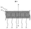
本実施例では、分析システム全体は実施例1と基本的に同じ構成であるが、液体搬送路10の構成が異なる。ここで、液体搬送路10は、測定部を除く部分について、第2の領域32と同様の性質を持つ第3の領域とする。第3の領域の親油性および溌油性および撥水性に関する性質は上記の第2の領域と同様である。図14に本実施例の液体搬送路を上部から見た場合の構成図を示す。簡単のため、制御電極及び第3の領域のみ示す。また図15に、液体搬送路において搬送方向と垂直な(B-B')方向の断面図を示す。液体搬送路中の制御電極21付近に、搬送方向に沿ってオイルとの親和性の高い第3の領域33’を設ける。第3の領域の外側には第1の領域と同様の性質を有する領域32’が設けられる。オイルはシリコーンオイルを用い、第3の領域33’の液体搬送デバイス表面の撥水膜にはシリコーン系撥水膜を用いて、他の液体搬送デバイス表面はフッ素系撥水膜であるTeflonAF(登録商標)を用いた。これまでの液体搬送デバイスでは、オイルとの親和性の制御はしていないため、液体の搬送などによりオイルが大きく流動し、試料1が制御電極が重ならない位置に移動してしまい、液体が制御できなくなることが考えられるが、本実施例の構成によりオイルが制御電極上から離れにくくすることで,確実に試料1を搬送することが可能となる。また実施例2で示したように、第3の領域とその他の液体搬送デバイス表面の撥水膜の材質は同じであるが、第3の領域の表面に凸凹形状をつけることにより、オイルとの親和性を高めてもよい。 In the present embodiment, the entire analysis system has basically the same configuration as that of the first embodiment, but the configuration of the
1…試料、2…オイル、3…空気、4…試料プローブ、5…オイルプローブ、6…導入口、7…シッパー、8…排出口、9…廃液タンク、10…液体搬送デバイス、11…試料ユニット、12…検出ユニット、13…排出ユニット、14…導入部、15…液体搬送路、16…測定部、17…排出部、18…下側基板、19…上側基板、20…基礎基板、20'…基礎基板、21…制御電極、21a…制御電極、21b…制御電極、21c…制御電極、21d…制御電極、21e…制御電極、21’…制御電極、22…絶縁膜、22'…絶縁膜、23…撥水膜、23'…撥水膜、24…共通電極、25…ハロゲンランプ、26…照射光ファイバ、27…照射レンズ、28…光、29…集光レンズ、30…集光光ファイバ、31…分光検出器、32…第1の領域、32’…第1の領域と同様の性質を有する領域、33…第2の領域、33’…第3の領域、34…光が照射される領域、101…電圧制御手段、102…制御用コンピュータ、103…連絡部。DESCRIPTION OF
Claims (23)
Translated fromJapanese前記第1の基礎基板上に設けられた複数の第1電極と、
第1の液体及び第2の液体を導入するための導入口と、
前記第1の液体及び前記第2の液体を排出するための排出口と、
前記第1の液体についての測定を行なうための測定部と、
前記複数の第1電極の少なくとも一部に電圧を印加する導電手段と、
前記測定部に設けられた第1の領域と、
前記第1の領域の近傍に設けられ、前記第1の領域よりも前記第2の液体に対する親和性の高い第2の領域とを有することを特徴とする液体搬送デバイス。A first basic substrate;
A plurality of first electrodes provided on the first base substrate;
An inlet for introducing the first liquid and the second liquid;
A discharge port for discharging the first liquid and the second liquid;
A measurement unit for performing measurement on the first liquid;
A conductive means for applying a voltage to at least a part of the plurality of first electrodes;
A first region provided in the measurement unit;
A liquid transporting device, comprising: a second region provided in the vicinity of the first region and having a higher affinity for the second liquid than the first region.
前記第2の基礎基板上に設けられた第2電極とをさらに有し、
前記導電手段は、前記第1電極の少なくとも一部と前記第2電極との間に電圧を印加することを特徴とする請求項1に記載の液体搬送デバイス。A second base substrate facing the first base substrate;
A second electrode provided on the second base substrate,
2. The liquid transport device according to claim 1, wherein the conductive means applies a voltage between at least a part of the first electrode and the second electrode.
前記第1の液体を供給する手段から吐出された前記第1の液体を導入する導入部と、前記第1の液体を導出する排出口と、複数の第1電極を備えてかつ前記導入部と前記排出口とをつなぐ液体搬送路と、前記液体搬送路の少なくとも一部に設けられた測定部と、前記複数の第1電極の少なくとも一部に電圧を印加する電圧印加手段を具備する第2のユニットと、
前記測定部で検出するための検出系を具備する第3のユニットと、
前記排出口から液体を排出するための第4のユニットとを有し、
前記第2のユニットは、前記測定部に設けられた第1の領域と、前記第1の領域の近傍に設けられ、前記第1の領域よりも前記第2の液体に対する親和性の高い第2の領域とを有し、前記電圧印加手段は、前記第1の液体を前記液体搬送路に沿って移動させるように、前記複数の第1電極の少なくとも一部に電圧を印加することを特徴とする分析システム。A first unit comprising means for supplying a first liquid and means for supplying a second liquid;
An introduction part for introducing the first liquid discharged from the means for supplying the first liquid; an outlet for deriving the first liquid; a plurality of first electrodes; and the introduction part; A liquid transport path connecting the discharge port; a measurement unit provided in at least a part of the liquid transport path; and a second voltage applying unit configured to apply a voltage to at least a part of the plurality of first electrodes. Unit of
A third unit comprising a detection system for detection by the measurement unit;
A fourth unit for discharging liquid from the discharge port,
The second unit is provided in the vicinity of the first region provided in the measurement unit and the first region, and the second unit has a higher affinity for the second liquid than the first region. And the voltage applying means applies a voltage to at least a part of the plurality of first electrodes so as to move the first liquid along the liquid transport path. Analysis system.
Priority Applications (1)
| Application Number | Priority Date | Filing Date | Title |
|---|---|---|---|
| JP2005156575AJP2006329904A (en) | 2005-05-30 | 2005-05-30 | Liquid transport device and analysis system |
Applications Claiming Priority (1)
| Application Number | Priority Date | Filing Date | Title |
|---|---|---|---|
| JP2005156575AJP2006329904A (en) | 2005-05-30 | 2005-05-30 | Liquid transport device and analysis system |
Publications (1)
| Publication Number | Publication Date |
|---|---|
| JP2006329904Atrue JP2006329904A (en) | 2006-12-07 |
Family
ID=37551727
Family Applications (1)
| Application Number | Title | Priority Date | Filing Date |
|---|---|---|---|
| JP2005156575APendingJP2006329904A (en) | 2005-05-30 | 2005-05-30 | Liquid transport device and analysis system |
Country Status (1)
| Country | Link |
|---|---|
| JP (1) | JP2006329904A (en) |
Cited By (41)
| Publication number | Priority date | Publication date | Assignee | Title |
|---|---|---|---|---|
| JP2009058231A (en)* | 2007-08-29 | 2009-03-19 | Shimadzu Corp | Method for analyzing samples in liquid |
| JP2010521676A (en)* | 2007-03-13 | 2010-06-24 | アドヴァンスト リキッド ロジック インコーポレイテッド | Droplet actuator apparatus, configuration and method for improved absorbance detection |
| JP2010524002A (en)* | 2007-04-10 | 2010-07-15 | アドヴァンスト リキッド ロジック インコーポレイテッド | Droplet dispensing apparatus and method |
| JP2013242321A (en)* | 2007-08-24 | 2013-12-05 | Advanced Liquid Logic Inc | Bead manipulation in droplet actuator |
| US8877512B2 (en) | 2009-01-23 | 2014-11-04 | Advanced Liquid Logic, Inc. | Bubble formation techniques using physical or chemical features to retain a gas bubble within a droplet actuator |
| US8883513B2 (en) | 2006-04-18 | 2014-11-11 | Advanced Liquid Logic, Inc. | Droplet-based particle sorting |
| US8927296B2 (en) | 2006-04-18 | 2015-01-06 | Advanced Liquid Logic, Inc. | Method of reducing liquid volume surrounding beads |
| US8951732B2 (en) | 2007-06-22 | 2015-02-10 | Advanced Liquid Logic, Inc. | Droplet-based nucleic acid amplification in a temperature gradient |
| US9011662B2 (en) | 2010-06-30 | 2015-04-21 | Advanced Liquid Logic, Inc. | Droplet actuator assemblies and methods of making same |
| US9012165B2 (en) | 2007-03-22 | 2015-04-21 | Advanced Liquid Logic, Inc. | Assay for B-galactosidase activity |
| US9050606B2 (en) | 2006-04-13 | 2015-06-09 | Advanced Liquid Logic, Inc. | Bead manipulation techniques |
| US9081007B2 (en) | 2006-04-18 | 2015-07-14 | Advanced Liquid Logic, Inc. | Bead incubation and washing on a droplet actuator |
| US9091649B2 (en) | 2009-11-06 | 2015-07-28 | Advanced Liquid Logic, Inc. | Integrated droplet actuator for gel; electrophoresis and molecular analysis |
| US9110017B2 (en) | 2002-09-24 | 2015-08-18 | Duke University | Apparatuses and methods for manipulating droplets |
| US9139865B2 (en) | 2006-04-18 | 2015-09-22 | Advanced Liquid Logic, Inc. | Droplet-based nucleic acid amplification method and apparatus |
| US9140635B2 (en) | 2011-05-10 | 2015-09-22 | Advanced Liquid Logic, Inc. | Assay for measuring enzymatic modification of a substrate by a glycoprotein having enzymatic activity |
| US9188615B2 (en) | 2011-05-09 | 2015-11-17 | Advanced Liquid Logic, Inc. | Microfluidic feedback using impedance detection |
| US9216415B2 (en) | 2005-05-11 | 2015-12-22 | Advanced Liquid Logic | Methods of dispensing and withdrawing liquid in an electrowetting device |
| US9223317B2 (en) | 2012-06-14 | 2015-12-29 | Advanced Liquid Logic, Inc. | Droplet actuators that include molecular barrier coatings |
| US9238222B2 (en) | 2012-06-27 | 2016-01-19 | Advanced Liquid Logic, Inc. | Techniques and droplet actuator designs for reducing bubble formation |
| US9248450B2 (en) | 2010-03-30 | 2016-02-02 | Advanced Liquid Logic, Inc. | Droplet operations platform |
| US9321049B2 (en) | 2007-02-15 | 2016-04-26 | Advanced Liquid Logic, Inc. | Capacitance detection in a droplet actuator |
| US9377455B2 (en) | 2006-04-18 | 2016-06-28 | Advanced Liquid Logic, Inc | Manipulation of beads in droplets and methods for manipulating droplets |
| US9446404B2 (en) | 2011-07-25 | 2016-09-20 | Advanced Liquid Logic, Inc. | Droplet actuator apparatus and system |
| US9476856B2 (en) | 2006-04-13 | 2016-10-25 | Advanced Liquid Logic, Inc. | Droplet-based affinity assays |
| JP6026027B1 (en)* | 2016-02-05 | 2016-11-16 | 国立大学法人秋田大学 | Rapid detection of biomolecules using electric field agitation |
| US9511369B2 (en) | 2007-09-04 | 2016-12-06 | Advanced Liquid Logic, Inc. | Droplet actuator with improved top substrate |
| US9513253B2 (en) | 2011-07-11 | 2016-12-06 | Advanced Liquid Logic, Inc. | Droplet actuators and techniques for droplet-based enzymatic assays |
| US9545640B2 (en) | 2009-08-14 | 2017-01-17 | Advanced Liquid Logic, Inc. | Droplet actuator devices comprising removable cartridges and methods |
| WO2017047082A1 (en)* | 2015-09-16 | 2017-03-23 | Sharp Kabushiki Kaisha | Microfluidic device and a method of loading fluid therein |
| US9631244B2 (en) | 2007-10-17 | 2017-04-25 | Advanced Liquid Logic, Inc. | Reagent storage on a droplet actuator |
| US9630180B2 (en) | 2007-12-23 | 2017-04-25 | Advanced Liquid Logic, Inc. | Droplet actuator configurations and methods of conducting droplet operations |
| US9675972B2 (en) | 2006-05-09 | 2017-06-13 | Advanced Liquid Logic, Inc. | Method of concentrating beads in a droplet |
| US9863913B2 (en) | 2012-10-15 | 2018-01-09 | Advanced Liquid Logic, Inc. | Digital microfluidics cartridge and system for operating a flow cell |
| US9861986B2 (en) | 2008-05-03 | 2018-01-09 | Advanced Liquid Logic, Inc. | Droplet actuator and method |
| US10078078B2 (en) | 2006-04-18 | 2018-09-18 | Advanced Liquid Logic, Inc. | Bead incubation and washing on a droplet actuator |
| US10379112B2 (en) | 2007-02-09 | 2019-08-13 | Advanced Liquid Logic, Inc. | Droplet actuator devices and methods employing magnetic beads |
| US10731199B2 (en) | 2011-11-21 | 2020-08-04 | Advanced Liquid Logic, Inc. | Glucose-6-phosphate dehydrogenase assays |
| WO2021005560A1 (en)* | 2019-07-10 | 2021-01-14 | National Research Council Of Canada | Oil residue protection in oil-encapsulated digital microfluidics |
| JP2022020665A (en)* | 2015-04-03 | 2022-02-01 | アボット・ラボラトリーズ | Devices and methods for sample analysis |
| US11255809B2 (en) | 2006-04-18 | 2022-02-22 | Advanced Liquid Logic, Inc. | Droplet-based surface modification and washing |
- 2005
- 2005-05-30JPJP2005156575Apatent/JP2006329904A/enactivePending
Cited By (74)
| Publication number | Priority date | Publication date | Assignee | Title |
|---|---|---|---|---|
| US9638662B2 (en) | 2002-09-24 | 2017-05-02 | Duke University | Apparatuses and methods for manipulating droplets |
| US9110017B2 (en) | 2002-09-24 | 2015-08-18 | Duke University | Apparatuses and methods for manipulating droplets |
| US9517469B2 (en) | 2005-05-11 | 2016-12-13 | Advanced Liquid Logic, Inc. | Method and device for conducting biochemical or chemical reactions at multiple temperatures |
| US9452433B2 (en) | 2005-05-11 | 2016-09-27 | Advanced Liquid Logic, Inc. | Method and device for conducting biochemical or chemical reactions at multiple temperatures |
| US9216415B2 (en) | 2005-05-11 | 2015-12-22 | Advanced Liquid Logic | Methods of dispensing and withdrawing liquid in an electrowetting device |
| US9050606B2 (en) | 2006-04-13 | 2015-06-09 | Advanced Liquid Logic, Inc. | Bead manipulation techniques |
| US9476856B2 (en) | 2006-04-13 | 2016-10-25 | Advanced Liquid Logic, Inc. | Droplet-based affinity assays |
| US9358551B2 (en) | 2006-04-13 | 2016-06-07 | Advanced Liquid Logic, Inc. | Bead manipulation techniques |
| US9205433B2 (en) | 2006-04-13 | 2015-12-08 | Advanced Liquid Logic, Inc. | Bead manipulation techniques |
| US9377455B2 (en) | 2006-04-18 | 2016-06-28 | Advanced Liquid Logic, Inc | Manipulation of beads in droplets and methods for manipulating droplets |
| US11525827B2 (en) | 2006-04-18 | 2022-12-13 | Advanced Liquid Logic, Inc. | Bead incubation and washing on a droplet actuator |
| US10139403B2 (en) | 2006-04-18 | 2018-11-27 | Advanced Liquid Logic, Inc. | Manipulation of beads in droplets and methods for manipulating droplets |
| US9081007B2 (en) | 2006-04-18 | 2015-07-14 | Advanced Liquid Logic, Inc. | Bead incubation and washing on a droplet actuator |
| US10585090B2 (en) | 2006-04-18 | 2020-03-10 | Advanced Liquid Logic, Inc. | Bead incubation and washing on a droplet actuator |
| US9097662B2 (en) | 2006-04-18 | 2015-08-04 | Advanced Liquid Logic, Inc. | Droplet-based particle sorting |
| US10809254B2 (en) | 2006-04-18 | 2020-10-20 | Advanced Liquid Logic, Inc. | Manipulation of beads in droplets and methods for manipulating droplets |
| US9139865B2 (en) | 2006-04-18 | 2015-09-22 | Advanced Liquid Logic, Inc. | Droplet-based nucleic acid amplification method and apparatus |
| US12332205B2 (en) | 2006-04-18 | 2025-06-17 | Advanced Liquid Logic, Inc. | Droplet-based surface modification and washing |
| US9494498B2 (en) | 2006-04-18 | 2016-11-15 | Advanced Liquid Logic, Inc. | Manipulation of beads in droplets and methods for manipulating droplets |
| US11255809B2 (en) | 2006-04-18 | 2022-02-22 | Advanced Liquid Logic, Inc. | Droplet-based surface modification and washing |
| US8927296B2 (en) | 2006-04-18 | 2015-01-06 | Advanced Liquid Logic, Inc. | Method of reducing liquid volume surrounding beads |
| US9395329B2 (en) | 2006-04-18 | 2016-07-19 | Advanced Liquid Logic, Inc. | Droplet-based particle sorting |
| US11789015B2 (en) | 2006-04-18 | 2023-10-17 | Advanced Liquid Logic, Inc. | Manipulation of beads in droplets and methods for manipulating droplets |
| US9243282B2 (en) | 2006-04-18 | 2016-01-26 | Advanced Liquid Logic, Inc | Droplet-based pyrosequencing |
| US9395361B2 (en) | 2006-04-18 | 2016-07-19 | Advanced Liquid Logic, Inc. | Bead incubation and washing on a droplet actuator |
| US10078078B2 (en) | 2006-04-18 | 2018-09-18 | Advanced Liquid Logic, Inc. | Bead incubation and washing on a droplet actuator |
| US8883513B2 (en) | 2006-04-18 | 2014-11-11 | Advanced Liquid Logic, Inc. | Droplet-based particle sorting |
| US9675972B2 (en) | 2006-05-09 | 2017-06-13 | Advanced Liquid Logic, Inc. | Method of concentrating beads in a droplet |
| US12181467B2 (en) | 2007-02-09 | 2024-12-31 | Advanced Liquid Logic, Inc. | Droplet actuator devices and methods employing magnetic beads |
| US10379112B2 (en) | 2007-02-09 | 2019-08-13 | Advanced Liquid Logic, Inc. | Droplet actuator devices and methods employing magnetic beads |
| US10183292B2 (en) | 2007-02-15 | 2019-01-22 | Advanced Liquid Logic, Inc. | Capacitance detection in a droplet actuator |
| US9321049B2 (en) | 2007-02-15 | 2016-04-26 | Advanced Liquid Logic, Inc. | Capacitance detection in a droplet actuator |
| JP2010521676A (en)* | 2007-03-13 | 2010-06-24 | アドヴァンスト リキッド ロジック インコーポレイテッド | Droplet actuator apparatus, configuration and method for improved absorbance detection |
| US9012165B2 (en) | 2007-03-22 | 2015-04-21 | Advanced Liquid Logic, Inc. | Assay for B-galactosidase activity |
| US9574220B2 (en) | 2007-03-22 | 2017-02-21 | Advanced Liquid Logic, Inc. | Enzyme assays on a droplet actuator |
| JP2010524002A (en)* | 2007-04-10 | 2010-07-15 | アドヴァンスト リキッド ロジック インコーポレイテッド | Droplet dispensing apparatus and method |
| EP2132296A4 (en)* | 2007-04-10 | 2015-04-08 | Advanced Liquid Logic Inc | Droplet dispensing device and methods |
| US8951732B2 (en) | 2007-06-22 | 2015-02-10 | Advanced Liquid Logic, Inc. | Droplet-based nucleic acid amplification in a temperature gradient |
| JP2013242321A (en)* | 2007-08-24 | 2013-12-05 | Advanced Liquid Logic Inc | Bead manipulation in droplet actuator |
| JP2009058231A (en)* | 2007-08-29 | 2009-03-19 | Shimadzu Corp | Method for analyzing samples in liquid |
| US9511369B2 (en) | 2007-09-04 | 2016-12-06 | Advanced Liquid Logic, Inc. | Droplet actuator with improved top substrate |
| US9631244B2 (en) | 2007-10-17 | 2017-04-25 | Advanced Liquid Logic, Inc. | Reagent storage on a droplet actuator |
| US9630180B2 (en) | 2007-12-23 | 2017-04-25 | Advanced Liquid Logic, Inc. | Droplet actuator configurations and methods of conducting droplet operations |
| US9861986B2 (en) | 2008-05-03 | 2018-01-09 | Advanced Liquid Logic, Inc. | Droplet actuator and method |
| US8877512B2 (en) | 2009-01-23 | 2014-11-04 | Advanced Liquid Logic, Inc. | Bubble formation techniques using physical or chemical features to retain a gas bubble within a droplet actuator |
| US9545641B2 (en) | 2009-08-14 | 2017-01-17 | Advanced Liquid Logic, Inc. | Droplet actuator devices and methods |
| US9545640B2 (en) | 2009-08-14 | 2017-01-17 | Advanced Liquid Logic, Inc. | Droplet actuator devices comprising removable cartridges and methods |
| US9707579B2 (en) | 2009-08-14 | 2017-07-18 | Advanced Liquid Logic, Inc. | Droplet actuator devices comprising removable cartridges and methods |
| US9091649B2 (en) | 2009-11-06 | 2015-07-28 | Advanced Liquid Logic, Inc. | Integrated droplet actuator for gel; electrophoresis and molecular analysis |
| US9952177B2 (en) | 2009-11-06 | 2018-04-24 | Advanced Liquid Logic, Inc. | Integrated droplet actuator for gel electrophoresis and molecular analysis |
| US9248450B2 (en) | 2010-03-30 | 2016-02-02 | Advanced Liquid Logic, Inc. | Droplet operations platform |
| US9910010B2 (en) | 2010-03-30 | 2018-03-06 | Advanced Liquid Logic, Inc. | Droplet operations platform |
| US9011662B2 (en) | 2010-06-30 | 2015-04-21 | Advanced Liquid Logic, Inc. | Droplet actuator assemblies and methods of making same |
| US9188615B2 (en) | 2011-05-09 | 2015-11-17 | Advanced Liquid Logic, Inc. | Microfluidic feedback using impedance detection |
| US9492822B2 (en) | 2011-05-09 | 2016-11-15 | Advanced Liquid Logic, Inc. | Microfluidic feedback using impedance detection |
| US9140635B2 (en) | 2011-05-10 | 2015-09-22 | Advanced Liquid Logic, Inc. | Assay for measuring enzymatic modification of a substrate by a glycoprotein having enzymatic activity |
| US9513253B2 (en) | 2011-07-11 | 2016-12-06 | Advanced Liquid Logic, Inc. | Droplet actuators and techniques for droplet-based enzymatic assays |
| US9446404B2 (en) | 2011-07-25 | 2016-09-20 | Advanced Liquid Logic, Inc. | Droplet actuator apparatus and system |
| US10731199B2 (en) | 2011-11-21 | 2020-08-04 | Advanced Liquid Logic, Inc. | Glucose-6-phosphate dehydrogenase assays |
| US9223317B2 (en) | 2012-06-14 | 2015-12-29 | Advanced Liquid Logic, Inc. | Droplet actuators that include molecular barrier coatings |
| US9815061B2 (en) | 2012-06-27 | 2017-11-14 | Advanced Liquid Logic, Inc. | Techniques and droplet actuator designs for reducing bubble formation |
| US9238222B2 (en) | 2012-06-27 | 2016-01-19 | Advanced Liquid Logic, Inc. | Techniques and droplet actuator designs for reducing bubble formation |
| US9863913B2 (en) | 2012-10-15 | 2018-01-09 | Advanced Liquid Logic, Inc. | Digital microfluidics cartridge and system for operating a flow cell |
| JP2022020665A (en)* | 2015-04-03 | 2022-02-01 | アボット・ラボラトリーズ | Devices and methods for sample analysis |
| US11998917B2 (en) | 2015-09-16 | 2024-06-04 | Sharp Life Science (Eu) Limited | Microfluidic device and a method of loading fluid therein |
| CN113376390A (en)* | 2015-09-16 | 2021-09-10 | 夏普生命科学(欧洲)有限公司 | Microfluidic device and method of filling fluid therein |
| US10926260B2 (en) | 2015-09-16 | 2021-02-23 | Sharp Life Science (Eu) Limited | Microfluidic device and a method of loading fluid therein |
| US12017223B2 (en) | 2015-09-16 | 2024-06-25 | Sharp Life Science (Eu) Limited | Microfluidic device and a method of loading fluid therein |
| WO2017047082A1 (en)* | 2015-09-16 | 2017-03-23 | Sharp Kabushiki Kaisha | Microfluidic device and a method of loading fluid therein |
| JP6026027B1 (en)* | 2016-02-05 | 2016-11-16 | 国立大学法人秋田大学 | Rapid detection of biomolecules using electric field agitation |
| US20220274112A1 (en)* | 2019-07-10 | 2022-09-01 | National Research Council Of Canada | Oil Residue Protection in Oil-Encapsulated Digital Microfluidics |
| EP3999831A4 (en)* | 2019-07-10 | 2024-01-10 | National Research Council of Canada | Oil residue protection in oil-encapsulated digital microfluidics |
| WO2021005560A1 (en)* | 2019-07-10 | 2021-01-14 | National Research Council Of Canada | Oil residue protection in oil-encapsulated digital microfluidics |
| JP7581258B2 (en) | 2019-07-10 | 2024-11-12 | ナショナル リサーチ カウンシル オブ カナダ | Oil Residue Protection in Oil-Filled Digital Microfluidics |
Similar Documents
| Publication | Publication Date | Title |
|---|---|---|
| JP2006329904A (en) | Liquid transport device and analysis system | |
| US7922885B2 (en) | Device for transporting liquid and system for analyzing | |
| US8128798B2 (en) | Liquid transfer device | |
| US7767147B2 (en) | Substrate for transporting liquid, a system for analysis and a method for analysis | |
| AU2024266940A1 (en) | Directing motion of droplets using differential wetting | |
| JP7433255B2 (en) | microfluidics chip | |
| US7048889B2 (en) | Dynamically controllable biological/chemical detectors having nanostructured surfaces | |
| US10189021B2 (en) | Microfluidic chip, manufacturing method therefor and analysis device using same | |
| Choi et al. | A 96-well microplate incorporating a replica molded microfluidic network integrated with photonic crystal biosensors for high throughput kinetic biomolecular interaction analysis | |
| US20200319135A1 (en) | Microfluidic chip and manufacturing method thereof and integrated microfluidic chip system | |
| CN108786942B (en) | Microfluidic chip, microfluidic device and control method thereof | |
| US20190329259A1 (en) | Digital microfluidic devices | |
| JP4252545B2 (en) | Microchannel and microfluidic chip | |
| CN104841499A (en) | Paper-based digital micro-fluidic device | |
| JP4935750B2 (en) | Bidirectional electrophoresis apparatus and bidirectional electrophoresis method | |
| CN119470354A (en) | A biological image detection system on a plasmon metasurface chip integrated with digital microfluidics | |
| US20090291025A1 (en) | Microchip And Method Of Using The Same | |
| WO2012173130A1 (en) | Liquid analyser | |
| JP4637610B2 (en) | Microchannel and microchip | |
| US10871449B2 (en) | SERS sensor apparatus with passivation film | |
| CN108195805A (en) | Microfluid sensing element and manufacturing method thereof | |
| JP4547304B2 (en) | Liquid transfer substrate and analysis system | |
| JP2006292599A (en) | Liquid transport mechanism | |
| CN111250181A (en) | Manufacturing method of optical waveguide multi-micro-channel chip based on CMOS image sensing |