JP2006328899A - Door handle device - Google Patents
Door handle deviceDownload PDFInfo
- Publication number
- JP2006328899A JP2006328899AJP2005157564AJP2005157564AJP2006328899AJP 2006328899 AJP2006328899 AJP 2006328899AJP 2005157564 AJP2005157564 AJP 2005157564AJP 2005157564 AJP2005157564 AJP 2005157564AJP 2006328899 AJP2006328899 AJP 2006328899A
- Authority
- JP
- Japan
- Prior art keywords
- antenna
- escutcheon
- end cover
- door handle
- fixed
- Prior art date
- Legal status (The legal status is an assumption and is not a legal conclusion. Google has not performed a legal analysis and makes no representation as to the accuracy of the status listed.)
- Granted
Links
- 230000004308accommodationEffects0.000description4
- 239000000463materialSubstances0.000description4
- 230000005540biological transmissionEffects0.000description3
- 230000002093peripheral effectEffects0.000description3
- 239000011347resinSubstances0.000description2
- 229920005989resinPolymers0.000description2
- 238000005352clarificationMethods0.000description1
- 230000001747exhibiting effectEffects0.000description1
- 238000007789sealingMethods0.000description1
Images


Landscapes
- Lock And Its Accessories (AREA)
Abstract
Description
Translated fromJapanese本発明は、送受信アンテナを有するドアハンドル装置に関する。 The present invention relates to a door handle device having a transmission / reception antenna.
近年、自動車のドア等のロックやロック解除をキー無しで行うことができるキーレスエントリーシステムが種々提案されている。そして、自動車のキーレスエントリーシステムに使用されるドアハンドル装置としては、特許文献1に記載されたものが知られている。 In recent years, various keyless entry systems have been proposed that can lock and unlock automobile doors and the like without a key. And what was described in
このドアハンドル装置100は、図7に示すように、ドアパネル(不図示)の表面に露出させた状態で固定されたエスカッション101と、このエスカッション101の外面に揺動自在に設けられたプルタイプのドアハンドル102と、エスカッション101の内面にネジ103で固定され、携帯機(不図示)との交信電波を送受信するためのアンテ104とを備えている。 As shown in FIG. 7, the
上記構成において、車両から降車して施錠する場合には、運転者等が車外に出てドアを閉じる。そして、運転者等が携帯機によってドア閉操作を行う。すると、携帯機と車体側の送受信手段がアンテナ104を介して無線で交信する。交信によって携帯機が制御手段に認証されると、制御手段がドアロック機構を施錠状態とする。これにより、携帯機を携帯しない者がドアハンドル102を開操作してもドアを開くことができない。 In the above configuration, when getting off the vehicle and locking, the driver or the like goes out of the vehicle and closes the door. And a driver etc. perform door closing operation with a portable machine. Then, the portable device and the transmission / reception means on the vehicle body side communicate wirelessly via the
又、施錠された車両に乗車する場合には、運転者等が携帯機によってドア開操作をする。すると、携帯機と車体側の交信手段がアンテナ104を介して無線で交信する。交信によって携帯機が制御手段に認証されると、制御手段がドアロック機構を解錠状態とする。これにより、運転者等のドアハンドル102の開操作によってドアを開けることができる。 In addition, when getting on a locked vehicle, a driver or the like opens the door with a portable device. Then, the communication means on the vehicle body side with the portable device communicates wirelessly via the
ところで、ドアハンドルがグリップタイプのものはドアハンドルが肉厚に構成されるため、ドアハンドルにアンテナを内蔵させることができるが、前記従来例のプルタイプのものは、ドアハンドル102が薄肉に構成されるため、ドアハンドル102にアンテナ104を内蔵できない。そのため、前記従来例のようにエスカッション101の内面にアンテナ104が配置される。
しかしながら、従来のドアハンドル装置100では、アンテナ104をエスカッション101の内面にネジ103で固定するため、アンテナ104の取付け作業性が悪いという問題があった。 However, in the conventional
そこで、本発明は、アンテナの取付け作業性が良いドアハンドル装置を提供することを目的とする。 SUMMARY OF THE INVENTION An object of the present invention is to provide a door handle device with good antenna mounting workability.
上記目的を達成する請求項1の発明は、ドアパネルの外面に露出された状態で配設されるエスカッションと、このエスカッションの外面側に配置されるドアハンドルと、該エスカッションの内面側を被うエンドカバーと、このエンドカバー、または該エスカッションのいずれか一方に形成されるアンテナ仮保持部と、このアンテナ仮保持部に支持されるアンテナとからなり、該エスカッションに該エンドカバーが固定されることによって、該アンテナ仮保持部に配置された該アンテナが、該エンドカバーと該エスカッションとの間に狭持・固定されることを特徴とする。 The invention according to
請求項2の発明は、請求項1記載のドアハンドル装置であって、前記アンテナ仮保持部は、前記エンドカバーに設けられたアンテナ収容室であり、前記エスカッションに該エンドカバーを固定する際に、該アンテナ収容室の入口を前記エスカッションが閉塞することで、前記アンテナが固定されることを特徴とする。 The invention according to claim 2 is the door handle device according to
請求項3の発明は、請求項1記載のドアハンドル装置であって、前記アンテナ仮保持部は、前記エスカッションに設けられたアンテナ係止部であり、前記エスカッションに該エンドカバーを固定する際に、該アンテナ係止部と前記アンテナが前記エンドカバーによって共に被われることで、前記アンテナが固定されることを特徴とする。 The invention according to
請求項1の発明によれば、エスカッション又はエンドカバーのアンテナ仮保持部にアンテナを仮保持し、エンドカバーをエスカッションに取付けするとこの取付けによってアンテナが固定される。従って、アンテナをネジ固定する場合に較べてアンテナの取付け作業性が良い。 According to the first aspect of the present invention, when the antenna is temporarily held in the antenna temporary holding portion of the escutcheon or the end cover and the end cover is attached to the escutcheon, the antenna is fixed by this attachment. Therefore, the antenna mounting workability is better than when the antenna is screwed.
請求項2の発明によれば、アンテナをエンドカバー側に仮保持することによってアンテナを固定できる。 According to the invention of claim 2, the antenna can be fixed by temporarily holding the antenna on the end cover side.
請求項3の発明によれば、アンテナをエスカッション側に仮保持することによってアンテナを固定できる。 According to the invention of
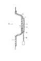
以下、本発明の実施形態を図面に基づいて説明する。図1〜図5は本発明の第1実施形態を示し、図1はドアハンドル装置1Aの正面図、図2はドアハンドル装置1Aの内面図、図3は図1のA−A線拡大断面図、図4は図1のB−B線断面図、図5はアンテナ6のエンドカバー5への仮保持作業を説明する断面図である。 Hereinafter, embodiments of the present invention will be described with reference to the drawings. 1 to 5 show a first embodiment of the present invention, FIG. 1 is a front view of a
図1〜図4に示すように、ドアハンドル装置1Aは、ドアパネル2の表面に露出させた状態で固定されたエスカッション3と、このエスカッション3の外面に揺動自在に設けられたプルタイプのドアハンドル4と、エスカッション3の内面を被うように配置されたエンドカバー5と、このエンドカバー5とエスカッション3の間に配置され、携帯機(不図示)との交信電波を送受信するためのアンテナ6とを備えている。 As shown in FIGS. 1 to 4, the
エスカッション3は、透磁性樹脂材にて形成されている。エスカッション3の内面で、且つ、アンテナ6が配置される位置の周辺位置には、圧入ボス7が複数突設されている。 The
ドアハンドル4は、プルタイプのものであり、操作者がドアパネル2に対して手前に引く(図3の矢印方向)ことによって閉位置から開位置に揺動される。 The door handle 4 is of a pull type, and is swung from the closed position to the open position when the operator pulls forward with respect to the door panel 2 (in the direction of the arrow in FIG. 3).
エンドカバー5は、樹脂材、ゴム材等のシール性の良い素材にて形成されている。エンドカバー5は、エスカッション3の内面のほぼ全域を被い、各圧入ボス7の対向位置には圧入孔(特に、符号を付さず)がそれぞれ設けられている。エンドカバー5の周縁部5aは、エスカッション3の周縁を被うように設けられている。そして、エスカッション3がドアパネル2に固定されると、エスカッション3とドアパネル2間にエンドカバー5が圧縮変形状態で介在されることによって防盗性、防水性等の機能を発揮するようになっている。 The end cover 5 is formed of a material having a good sealing property such as a resin material or a rubber material. The end cover 5 covers almost the entire area of the inner surface of the
又、エンドカバー5には、その内面側(エスカッション3側)に開口するアンテナ収容室8が設けられている。アンテナ収容室8の入口は奥側(アンテナ6の幅)に較べて若干狭く設定され、アンテナ収容室8の入口側を広げる方向に弾性変形することによってアンテナ6がアンテナ収容室8に収容されるようになっている。アンテナ6がアンテナ収容室8に収容されると、アンテナ収容室8の入口側が弾性復帰変形してアンテナ6が仮保持される。エンドカバー5には、アンテナ収容室8の近傍位置にハーネス導出孔9が形成され、このハーネス導出孔9よりアンテナ6のハーネス6aが外に導き出されている。 The end cover 5 is provided with an
上記構成において、車両から降車して施錠する場合には、運転者等が車外に出てドアを閉じる。そして、運転者等が携帯機(不図示)によってドア閉操作を行う。すると、携帯機と車体側の送受信手段がアンテナ6を介して無線で交信する。交信によって携帯機が制御手段に認証されると、制御手段がドアロック機構を施錠状態とする。これにより、携帯機を携帯しない者がドアハンドル4を開操作してもドアを開くことができない。 In the above configuration, when getting off the vehicle and locking, the driver or the like goes out of the vehicle and closes the door. And a driver etc. perform door closing operation with a portable machine (not shown). Then, the portable device and the transmission / reception means on the vehicle body communicate wirelessly via the
又、施錠された車両に乗車する場合には、運転者等が携帯機によってドア開操作をする。すると、携帯機と車体側の交信手段がアンテナ6を介して無線で交信する。交信によって携帯機が制御手段に認証されると、制御手段がドアロック機構を解錠状態とする。これにより、運転者等のドアハンドル4の開操作によってドアを開けることができる。 In addition, when getting on a locked vehicle, a driver or the like opens the door with a portable device. Then, the communication means on the side of the portable device and the vehicle body communicates wirelessly via the
次に、アンテナ6の取付け作業を説明する。図5に示すように、エンドカバー5の内面側からアンテナ6及びハーネス6aをa矢印方向に移動し、アンテナ6のハーネス6aをエンドカバー5のハーネス導出孔9より外側に導き出す。次に、アンテナ6をb矢印方向に移動してエンドカバー5のアンテナ収容室8に収容する。これによって、アンテナ6はエンドカバー5に仮保持される。そして、アンテナ6を仮保持したエンドカバー5をエスカッション3の内面側に取付けすれば、アンテナ6が同時に取付けされる。つまり、エンドカバー5がエスカッション3に固定されると、アンテナ収容室8の入口がエスカッション3で閉塞されることによってアンテナ6がエンドカバー5とエスカッション3の間に固定される。 Next, the mounting operation of the
以上、このドアハンドル装置1Aでは、エンドカバー5のアンテナ仮保持部であるアンテナ収容室8にアンテナ6を収容し、エンドカバー5をエスカッション3に取付けするとこの取付けによってアンテナ6が固定される。従って、従来例のようにアンテナ6をネジ固定する場合に較べてアンテナ6の取付け作業性が良い。又、ネジ等の取付具が不要であるためにコストダウン化が図れる。 As described above, in this
この第1実施形態では、アンテナ6をエンドカバー5側に仮保持することによってアンテナ6を固定できる。 In the first embodiment, the
この第1実施形態では、エスカッション3の圧入ボス7とエンドカバー5の圧入孔(図示せず)によってエンドカバー5のアンテナ収容室8がエスカッション3より浮き上がることを防止しているため、アンテナ6を確実に固定できる。 In the first embodiment, the
この第1実施形態では、アンテナ6は、エスカッション3との間にクリアランスdを介して配置されるため、エスカッション3からの振動が直接にアンテナ6に伝達されることがない。従って、アンテナ6を振動に強く設置できる。 In the first embodiment, since the
この第1実施形態では、アンテナ6は、エスカッション3とエンドカバー5によってほぼ全周囲が被われるため、防水性、防塵性等に優れている。 In the first embodiment, since the
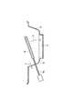
図6は本発明の第2実施形態に係るドアハンドル装置1Bの断面図である。図6において、この第2実施形態のドアハンドル装置1Bでは、アンテナ仮保持部がエスカッション3側に設けられている。つまり、エスカッション3の内面に仮保持部であるアンテナ係止部10が突設され、このアンテナ係止部にアンテナ6を係止されることによってアンテナ6を仮保持できるようになっている。アンテナ6を仮保持したエンドカバー5がエスカッション3に固定されると、アンテナ係止部10及びアンテナ6がエンドカバー5で共に被われることによってアンテナ6がエンドカバー5とエスカッション3の間に固定される。 FIG. 6 is a sectional view of a
他の構成は、前記第1実施形態と同様であるため、説明を省略する。図面の同一構成箇所には、同一符号を付して明確化を図る。 Since other configurations are the same as those of the first embodiment, description thereof will be omitted. The same components in the drawings are given the same reference numerals for clarification.
この第2実施形態のドアハンドル装置1Bでも、従来例のようにアンテナ6をネジ固定する場合に較べてアンテナ6の取付け作業性が良い。又、ネジ等の取付具が不要であるためにコストダウン化が図れる。 Even in the
この第2実施形態では、アンテナ6をエスカッション3側に仮保持することによってアンテナ6を固定できる。 In the second embodiment, the
この第2実施形態では、アンテナ6は、エスカッション3とエンドカバー5によってほぼ全周囲が被われるため、防水性、防塵性等に優れている。 In the second embodiment, since the
尚、アンテナ仮保持部は、前記第1実施形態では、エンドカバー5に設けられたアンテナ収容室8にて構成され、前記第2実施形態では、エスカッション3に設けられたアンテナ係止部10にて構成されたが、アンテナ仮保持部の構成はこれらに限定されるものではなく、アンテナ6を仮保持できるものであれが良い。 In the first embodiment, the antenna temporary holding portion is configured by the
1A,1B ドアハンドル装置
2 ドアパネル
3 エスカッション
4 ドアハンドル
5 エンドカバー
6 アンテナ
8 アンテナ収容室(アンテナ仮保持部)
10 アンテナ係止部(アンテナ仮保持部)1A, 1B Door handle device 2
10 Antenna locking part (antenna temporary holding part)
Claims (3)
Translated fromJapaneseこのエスカッションの外面側に配置されるドアハンドルと、
該エスカッションの内面側を被うエンドカバーと、
このエンドカバー、または該エスカッションのいずれか一方に形成されるアンテナ仮保持部と、
このアンテナ仮保持部に支持されるアンテナとからなり、
該エスカッションに該エンドカバーが固定されることによって、該アンテナ仮保持部に配置された該アンテナが、該エンドカバーと該エスカッションとの間に狭持・固定されることを特徴とするドアハンドル装置。An escutcheon that is exposed on the outer surface of the door panel;
A door handle arranged on the outer surface side of this escutcheon,
An end cover covering the inner side of the escutcheon;
An antenna temporary holding portion formed on either the end cover or the escutcheon,
It consists of an antenna supported by this antenna temporary holding part,
By fixing the end cover to the escutcheon, the antenna disposed in the antenna temporary holding portion is sandwiched and fixed between the end cover and the escutcheon. .
前記アンテナ仮保持部は、前記エンドカバーに設けられたアンテナ収容室であり、
前記エスカッションに該エンドカバーを固定する際に、該アンテナ収容室の入口を前記エスカッションが閉塞することで、前記アンテナが固定されることを特徴とするドアハンドル装置。The door handle device according to claim 1,
The antenna temporary holding portion is an antenna accommodating chamber provided in the end cover,
The door handle device characterized in that when the end cover is fixed to the escutcheon, the antenna is fixed by closing the entrance of the antenna accommodating chamber with the escutcheon.
前記アンテナ仮保持部は、前記エスカッションに設けられたアンテナ係止部であり、
前記エスカッションに該エンドカバーを固定する際に、該アンテナ係止部と前記アンテナが前記エンドカバーによって共に被われることで、前記アンテナが固定されることを特徴とするドアハンドル装置。
The door handle device according to claim 1,
The antenna temporary holding portion is an antenna locking portion provided in the escutcheon,
When the end cover is fixed to the escutcheon, the antenna locking portion and the antenna are covered together by the end cover, whereby the antenna is fixed.
Priority Applications (1)
| Application Number | Priority Date | Filing Date | Title |
|---|---|---|---|
| JP2005157564AJP4468242B2 (en) | 2005-05-30 | 2005-05-30 | Door handle device |
Applications Claiming Priority (1)
| Application Number | Priority Date | Filing Date | Title |
|---|---|---|---|
| JP2005157564AJP4468242B2 (en) | 2005-05-30 | 2005-05-30 | Door handle device |
Publications (2)
| Publication Number | Publication Date |
|---|---|
| JP2006328899Atrue JP2006328899A (en) | 2006-12-07 |
| JP4468242B2 JP4468242B2 (en) | 2010-05-26 |
Family
ID=37550860
Family Applications (1)
| Application Number | Title | Priority Date | Filing Date |
|---|---|---|---|
| JP2005157564AExpired - Fee RelatedJP4468242B2 (en) | 2005-05-30 | 2005-05-30 | Door handle device |
Country Status (1)
| Country | Link |
|---|---|
| JP (1) | JP4468242B2 (en) |
Cited By (3)
| Publication number | Priority date | Publication date | Assignee | Title |
|---|---|---|---|---|
| EP2230367A2 (en) | 2009-03-18 | 2010-09-22 | Aisin Seiki Kabushiki Kaisha | Door handle apparatus for vehicle |
| JP2017089311A (en)* | 2015-11-13 | 2017-05-25 | 株式会社ホンダロック | Vehicle out-handle device |
| JP2021526603A (en)* | 2018-05-25 | 2021-10-07 | ユーシン イタリア ソチエタ ペル アツィオーニ | Steering wheel device for vehicle door panels |
Families Citing this family (1)
| Publication number | Priority date | Publication date | Assignee | Title |
|---|---|---|---|---|
| JP2024119546A (en)* | 2023-02-22 | 2024-09-03 | 株式会社アルファ | Vehicle door opening/closing device |
- 2005
- 2005-05-30JPJP2005157564Apatent/JP4468242B2/ennot_activeExpired - Fee Related
Cited By (4)
| Publication number | Priority date | Publication date | Assignee | Title |
|---|---|---|---|---|
| EP2230367A2 (en) | 2009-03-18 | 2010-09-22 | Aisin Seiki Kabushiki Kaisha | Door handle apparatus for vehicle |
| JP2017089311A (en)* | 2015-11-13 | 2017-05-25 | 株式会社ホンダロック | Vehicle out-handle device |
| JP2021526603A (en)* | 2018-05-25 | 2021-10-07 | ユーシン イタリア ソチエタ ペル アツィオーニ | Steering wheel device for vehicle door panels |
| JP7419624B2 (en) | 2018-05-25 | 2024-01-23 | ユーシン イタリア ソチエタ ペル アツィオーニ | Handle device for vehicle door panel |
Also Published As
| Publication number | Publication date |
|---|---|
| JP4468242B2 (en) | 2010-05-26 |
Similar Documents
| Publication | Publication Date | Title |
|---|---|---|
| JP3835427B2 (en) | Portable transmitter | |
| JP3922204B2 (en) | Portable transmitter | |
| US20140125071A1 (en) | Vehicle door handle assembly with concealed key cylinder | |
| KR101840259B1 (en) | Remote door system using vehicle original remote controller and remote door control method | |
| JP3696866B2 (en) | Door opener | |
| US10647183B2 (en) | Vehicle closure panel assembly and carrier assembly therefor | |
| US6886874B2 (en) | Finisher for a vehicle | |
| JP4468242B2 (en) | Door handle device | |
| JP2005068723A (en) | Door latch device for vehicle | |
| EP3681789B1 (en) | An automated handle bar lock for vehicles | |
| JP4864610B2 (en) | Vehicle door handle device and manufacturing method thereof | |
| EP1172242A1 (en) | Door module | |
| JP4136880B2 (en) | Door lock device | |
| US12297667B2 (en) | Electronic vehicle latch with separately attached control unit | |
| JP2008074292A (en) | Immobilizer system | |
| JP2007196957A (en) | Rear part opening/closing structure for automobile | |
| JP3639292B1 (en) | Door opener | |
| JP2005041413A (en) | Door structure for automobile | |
| JP2005282222A (en) | Door locking device | |
| JP4096240B2 (en) | Vehicle door antenna device | |
| JP4002100B2 (en) | Assembly structure of door lock device | |
| JP2005124070A (en) | Remote controller | |
| JP2007291624A (en) | Portable machine of electronic key system | |
| JP2023131314A (en) | Electric lock control device | |
| JP2005307485A (en) | Antenna device and portable keyless device |
Legal Events
| Date | Code | Title | Description |
|---|---|---|---|
| A621 | Written request for application examination | Free format text:JAPANESE INTERMEDIATE CODE: A621 Effective date:20071226 | |
| A977 | Report on retrieval | Free format text:JAPANESE INTERMEDIATE CODE: A971007 Effective date:20100204 | |
| TRDD | Decision of grant or rejection written | ||
| A01 | Written decision to grant a patent or to grant a registration (utility model) | Free format text:JAPANESE INTERMEDIATE CODE: A01 Effective date:20100209 | |
| A01 | Written decision to grant a patent or to grant a registration (utility model) | Free format text:JAPANESE INTERMEDIATE CODE: A01 | |
| A61 | First payment of annual fees (during grant procedure) | Free format text:JAPANESE INTERMEDIATE CODE: A61 Effective date:20100224 | |
| R150 | Certificate of patent or registration of utility model | Free format text:JAPANESE INTERMEDIATE CODE: R150 | |
| FPAY | Renewal fee payment (event date is renewal date of database) | Free format text:PAYMENT UNTIL: 20130305 Year of fee payment:3 | |
| FPAY | Renewal fee payment (event date is renewal date of database) | Free format text:PAYMENT UNTIL: 20130305 Year of fee payment:3 | |
| FPAY | Renewal fee payment (event date is renewal date of database) | Free format text:PAYMENT UNTIL: 20130305 Year of fee payment:3 | |
| FPAY | Renewal fee payment (event date is renewal date of database) | Free format text:PAYMENT UNTIL: 20140305 Year of fee payment:4 | |
| LAPS | Cancellation because of no payment of annual fees |