Movatterモバイル変換


[0]ホーム

URL:


JP2006328639A - Self-propelled working machine - Google Patents

Self-propelled working machine
Download PDF

Info

Publication number
JP2006328639A
JP2006328639AJP2005149210AJP2005149210AJP2006328639AJP 2006328639 AJP2006328639 AJP 2006328639AJP 2005149210 AJP2005149210 AJP 2005149210AJP 2005149210 AJP2005149210 AJP 2005149210AJP 2006328639 AJP2006328639 AJP 2006328639A
Authority
JP
Japan
Prior art keywords
self
operating means
valve
propelled
overhang
Prior art date
Legal status (The legal status is an assumption and is not a legal conclusion. Google has not performed a legal analysis and makes no representation as to the accuracy of the status listed.)
Granted
Application number
JP2005149210A
Other languages
Japanese (ja)
Other versions
JP4824341B2 (en
Inventor
Naohiro Kobayashi
直廣 小林
Shozo Fujiwara
省三 藤原
Current Assignee (The listed assignees may be inaccurate. Google has not performed a legal analysis and makes no representation or warranty as to the accuracy of the list.)
HOKUTO KENKI SERVICE KK
Kobelco Construction Machinery Co Ltd
Original Assignee
HOKUTO KENKI SERVICE KK
Kobelco Construction Machinery Co Ltd
Priority date (The priority date is an assumption and is not a legal conclusion. Google has not performed a legal analysis and makes no representation as to the accuracy of the date listed.)
Filing date
Publication date
Application filed by HOKUTO KENKI SERVICE KK, Kobelco Construction Machinery Co LtdfiledCriticalHOKUTO KENKI SERVICE KK
Priority to JP2005149210ApriorityCriticalpatent/JP4824341B2/en
Publication of JP2006328639ApublicationCriticalpatent/JP2006328639A/en
Application grantedgrantedCritical
Publication of JP4824341B2publicationCriticalpatent/JP4824341B2/en
Anticipated expirationlegal-statusCritical
Expired - Fee Relatedlegal-statusCriticalCurrent

Links

Images

Landscapes

Abstract

Translated fromJapanese

【課題】 オペレータの負担の軽減を図りながら自走式作業機械が傾斜路から上側目標地へ円滑に乗り上げることができるようにする。
【解決手段】 下部走行体14に対して上部作業体16が通常位置とこの通常位置から傾斜路28の上り側に傾斜する傾斜位置との間で相対移動可能となるようにする。下部走行体14には、その下面よりも下方に張出して当該下部走行体14を傾斜状態に支持する張出し位置と、この張出し位置から上側に待避して下部走行体14の通常走行を可能にする格納位置とに切換可能な張出し部材50を設ける。さらに、前記傾斜路28からこれに続く上側目標地29への乗り上げ時に通常位置への下部走行体14の戻し操作と張出し部材50の格納操作とを同調させる制御手段を備える。
【選択図】 図2
PROBLEM TO BE SOLVED: To enable a self-propelled working machine to smoothly run from a ramp to an upper target site while reducing the burden on an operator.
SOLUTION: An upper working body 16 is movable relative to a lower traveling body 14 between a normal position and an inclined position inclined from the normal position to the upside of an inclined road 28. The lower traveling body 14 projects downward from the lower surface thereof to support the lower traveling body 14 in an inclined state, and the lower traveling body 14 is retracted upward from the projecting position to enable normal traveling of the lower traveling body 14. An overhang member 50 that can be switched to the storage position is provided. Furthermore, a control means for synchronizing the returning operation of the lower traveling body 14 to the normal position and the retracting operation of the overhanging member 50 at the time of getting on the upper target place 29 from the ramp 28 is provided.
[Selection] Figure 2

Description

Translated fromJapanese

本発明は、油圧ショベル等の自走式作業機械であって、上部作業体を略水平な状態に保ちながら階段や急斜面等の傾斜路を昇降可能な機能を有するものに関する。  The present invention relates to a self-propelled working machine such as a hydraulic excavator, which has a function capable of moving up and down ramps such as stairs and steep slopes while keeping an upper working body in a substantially horizontal state.

従来、階段や急斜面を安定した状態で走行できるようにした自走式作業機械として、特許文献1に記載されるものが知られている。この作業機械は、クローラ式の走行車において、その下部走行体上に対して上部作業体を前端側の支軸回りに回動可能(すなわち上部作業体の後端が起伏可能)となるように連結し、その回動により、前記上部作業体が前記下部走行体に対して略平行な通常姿勢と前傾姿勢とをとり得るようにしたものである。このような作業機械によれば、前記上部作業体を前記傾斜路の傾斜角度と略等しい角度まで前傾させながら当該傾斜路を走行させることにより、当該傾斜路の傾きにかかわらず前記上部作業体が略水平状態に維持される安定した姿勢で前記傾斜路の昇降を行うことが可能になる。
特開平11−334656号公報
Conventionally, as a self-propelled working machine capable of traveling on stairs and steep slopes in a stable state, one described in Patent Document 1 is known. In this work machine, in a crawler type traveling vehicle, the upper working body can be rotated around the support shaft on the front end side with respect to the lower traveling body (that is, the rear end of the upper working body can be raised and lowered). By connecting and rotating, the upper working body can take a normal posture and a forward leaning posture substantially parallel to the lower traveling body. According to such a working machine, the upper working body is caused to travel forward while the upper working body is tilted forward to an angle substantially equal to the inclination angle of the inclined road, so that the upper working body is independent of the inclination of the inclined road. It is possible to raise and lower the ramp with a stable posture that is maintained in a substantially horizontal state.
JP-A-11-334656

前記特許文献1に記載される走行車では、模擬的に図12に示すように、走行車200が前記傾斜路202からその上端につながる上側目標地(例えば階段頂上)204に乗り上げる際、それまでの傾斜姿勢(実線で図示)から水平姿勢(二点鎖線で図示)に急変する。その際、前記走行車200における下部走行体206の上端は前記上側目標地204に対して相当の高さ位置から急激に着地することになる。このような姿勢の急変は、走行車200に大きな衝撃を与えるおそれがある。また、前記上側目標地204の奥行きが狭くて当該上側目標地204の前方に例えば図示のような壁208が迫っている場合には、前記下部走行体206に対して前傾姿勢にある上部作業体210が前記壁208に接触するおそれもある。  In the traveling vehicle described in Patent Document 1, as shown in FIG. 12, when thetraveling vehicle 200 rides on the upper target site (for example, the top of the stairs) 204 connected to the upper end of theramp 202, Suddenly changes from an inclined posture (shown by a solid line) to a horizontal posture (shown by a two-dot chain line). At that time, the upper end of the lower travelingbody 206 in thetraveling vehicle 200 suddenly lands with respect to theupper target place 204 from a considerable height position. Such a sudden change in posture may give a large impact to thetraveling vehicle 200. In addition, when the depth of theupper target place 204 is narrow and awall 208 as shown in the drawing is approaching the front of theupper target place 204, the upper work in a forward leaning posture with respect to thelower traveling body 206 There is also a risk that thebody 210 contacts thewall 208.

このような不都合を回避する手段として、例えば特開平7−81634号公報に記載されるようなフロントアタッチメントを前記下部走行体206に設け、前記走行車200が前記上側目標地204に乗り上げる手前の位置で前記フロントアタッチメントを前記上側目標地204上に張出させ、その後に下部走行体206を徐行させながら前記フロントアタッチメントを少しずつ格納させて当該下部走行体206の前端を前記上側目標地204に静かに着地させることが考えられる。  As a means for avoiding such inconvenience, for example, a front attachment as described in Japanese Patent Application Laid-Open No. 7-81634 is provided in the lower travelingbody 206, and a position before the travelingvehicle 200 rides on theupper target place 204 is provided. Then, the front attachment is extended over theupper target place 204, and then thelower attachment 206 is gradually stored while the lower runningbody 206 is slowly moved so that the front end of the lower runningbody 206 is quietly placed on theupper target place 204. It is possible to land on.

しかしながら、このような着地を実現するためには、前記フロントアタッチメントの格納操作と並行して前記上部作業体210を前傾姿勢から通常姿勢に戻す操作をしなければならず、オペレータの負担が大きくなる。  However, in order to realize such landing, it is necessary to perform an operation of returning theupper work body 210 from the forward tilted posture to the normal posture in parallel with the storing operation of the front attachment, which places a heavy burden on the operator. Become.

本発明は、このような事情に鑑み、オペレータの負担の軽減を図りながら傾斜路から上側目標地への円滑な乗り上げを可能にする自走式作業機械の提供を目的とする。  In view of such circumstances, an object of the present invention is to provide a self-propelled working machine that enables a smooth ride from an inclined road to an upper target site while reducing the burden on an operator.

前記課題を解決するための手段として、本発明は、下部走行体及びその上に搭載される上部作業体を備え、前記下部走行体の走行により傾斜路の昇降が可能な自走式作業機械において、前記下部走行体に対して前記上部作業体が通常位置とこの通常位置から前記傾斜路の上り側に傾斜する傾斜位置との間で相対移動可能となるように当該下部走行体に支持されるとともに、この上部作業体を前記通常位置と前記傾斜位置との間で移動させる上部作業体操作手段と、前記下部走行体の下面よりも下方に張出して当該下部走行体を傾斜状態に支持する張出し位置とこの張出し位置から上側に待避して前記下部走行体の通常走行を可能にする格納位置とに切換可能な張出し部材と、この張出し部材を前記張出し位置と前記格納位置との間で移動させる張出し部材操作手段と、前記張出し部材が前記張出し位置から前記格納位置へ格納される際に前記上部作業体が略水平状態を維持するように、前記上部作業体操作手段による前記傾斜位置から前記通常位置への前記上部作業体の戻し操作と前記張出し部材操作手段による前記張出し位置から前記格納位置への格納操作とを同調させる操作制御手段とを備えたものである。  As a means for solving the above-mentioned problems, the present invention provides a self-propelled working machine including a lower traveling body and an upper working body mounted thereon, and capable of moving up and down an inclined road by traveling the lower traveling body. The upper working body is supported by the lower traveling body so as to be relatively movable with respect to the lower traveling body between a normal position and an inclined position inclined from the normal position to the upside of the slope. And an upper working body operating means for moving the upper working body between the normal position and the inclined position, and an overhang that projects downward from the lower surface of the lower traveling body to support the lower traveling body in an inclined state. A projecting member that can be switched between a position and a retracted position that is retracted upward from the projecting position to enable normal travel of the lower traveling body, and the projecting member is moved between the projecting position and the retracted position. The overhang member operating means and the normal position from the inclined position by the upper work body operating means so that the upper work body maintains a substantially horizontal state when the overhang member is stored from the overhang position to the retracted position. Operation control means for synchronizing the return operation of the upper working body to the position and the storage operation from the extended position to the storage position by the extended member operating means is provided.

この構成によれば、上部作業体操作手段により上部作業体を傾斜位置まで傾斜させた状態で、当該上部作業体を略水平な状態に維持したまま傾斜路を昇降することができる。そして、前記傾斜路の登坂時において、前記下部走行体が前記傾斜路の上端に続く略水平な上側目標地に乗り上げる直前の位置まで到達した時点で、その張出し部材を張出し位置まで張出した後、この張出し部材をその張出し位置から格納位置まで格納する格納操作と、前記上部作業体を前記傾斜位置から前記通常位置まで戻す戻し操作とを同調させる制御を操作制御手段に行わせながら、前記上側目標地に向けて下部走行体を徐行させることにより、オペレータの大きな負担を伴うことなく、前記上部作業体を略水平な状態に維持しながら下部走行体を前記傾斜路から前記上側目標地へ静かに乗り上げさせることができる。  According to this configuration, it is possible to move up and down the ramp while maintaining the upper working body in a substantially horizontal state in a state where the upper working body is inclined to the inclined position by the upper working body operating means. And at the time of climbing the ramp, when the lower traveling body has reached the position just before riding on the substantially horizontal upper target land following the upper end of the ramp, after projecting the projecting member to the projecting position, While the operation control means performs control to synchronize the storing operation of storing the protruding member from the extended position to the storage position and the returning operation of returning the upper working body from the inclined position to the normal position, the upper target By slowly moving the lower traveling body toward the ground, the lower traveling body is gently moved from the ramp to the upper target place while maintaining the upper working body in a substantially horizontal state without causing a heavy burden on the operator. You can get on.

さらに、前記操作制御手段が、前記上部作業体の戻し操作と前記張出し部材の格納操作との同調に加え、前記張出し部材が前記格納位置から前記張出し位置へ張出される際に前記上部作業体が略水平状態を維持するように、前記上部作業体操作手段による前記通常位置から前記傾斜位置への前記上部作業体の傾き操作と前記張出し部材操作手段による前記格納位置から前記張出し位置への張出し操作とを同調させるものであれば、その傾き操作と張出し操作とを同調させる制御によって、前記上側目標地から前記傾斜路への移行時(下降時)もオペレータの大きな負担を伴うことなく前記上部作業体を略水平な状態に維持しながら行うことが可能になる。  Further, in addition to the operation control means synchronizing the return operation of the upper working body and the retracting operation of the overhanging member, the upper working body is moved when the overhanging member is extended from the retracted position to the extended position. Inclination operation of the upper working body from the normal position to the inclined position by the upper working body operating means and overhanging operation from the retracted position to the extended position by the overhanging member operating means so as to maintain a substantially horizontal state. If the system is synchronized with the tilting operation and the overhanging operation, the upper work can be performed without a heavy burden on the operator even when shifting from the upper target site to the ramp (descent). It is possible to carry out while maintaining the body in a substantially horizontal state.

ここで、前記張出し部材の張出し位置は、少なくとも前記下部走行体の下面よりも下方に突出する位置であればよいが、前記下部走行体が前記傾斜路の上端に続く略水平な上側目標地に乗り上げる直前の位置にあるときに当該張出し部材が前記上側目標地に着地もしくは近接する位置に設定されていれば、下部走行体が傾斜路から上側目標地に乗り上げる際に自走式作業機械が上側目標地から受ける衝撃を皆無もしくはきわめて有効に低減することが可能となる。  Here, the projecting position of the projecting member may be a position that protrudes at least below the lower surface of the lower traveling body, but the lower traveling body is located at a substantially horizontal upper target place that continues to the upper end of the ramp. If the overhanging member is set at a position where it is landed on or close to the upper target place when it is in a position immediately before riding, the self-propelled work machine moves upward when the lower traveling body rides on the upper target place from the ramp. It is possible to reduce the impact received from the target place without any or very effectively.

また、前記操作制御手段が、前記同調の制御を行う同調制御モードと、前記上部作業体操作手段及び前記張出し部材操作手段をそれぞれ相互独立して作動させる独立制御モードとに切換可能なものであれば、オペレータにその好みに応じた操作を提供することができる。例えば、前記同調制御の使用が苦手なオペレータは、前記独立制御モードを選択することにより、自らの感覚で前記上部作業体操作手段による上部作業体の戻し操作と前記張出し部材操作手段による張出し部材の格納操作とをそれぞれ個別に行いながら上側目標地への乗り上げを行うことも可能になる。  Further, the operation control means can be switched between a tuning control mode for controlling the tuning and an independent control mode for operating the upper work body operating means and the extension member operating means independently of each other. Thus, an operation according to the preference can be provided to the operator. For example, an operator who is not good at using the synchronization control selects the independent control mode, so that the upper work body return operation by the upper work body operation means and the overhang member operation by the overhang member operation means can be performed with his / her own sense. It is also possible to get on the upper target place while performing the storing operation individually.

より具体的な態様としては、前記同調を指令する同調指令と、前記張出し部材操作手段とは独立した前記上部作業体操作手段の作動を指令する上部作業体操作指令と、前記上部作業体操作手段とは独立した前記張出し部材操作手段の作動を指令する張出し部材操作指令とが入力可能な指令入力手段を備え、前記操作制御手段は、前記同調指令が入力されたときには前記同調制御モードに切換えられ、前記上部作業体操作指令または前記張出し部材操作指令が入力されたときは前記独立制御モードに切換えられてその操作指令に基づいて前記上部作業体操作手段または前記張出し部材操作手段を個別に作動させるものが、好適である。  More specifically, as a tuning command for commanding the tuning, an upper work body operation command for commanding an operation of the upper work body operating means independent of the overhang member operating means, and the upper work body operating means Command input means capable of inputting an extension member operation command for commanding the operation of the extension member operation means independent of the operation control means, and the operation control means is switched to the tuning control mode when the tuning command is input. When the upper work body operation command or the overhang member operation command is input, the operation mode is switched to the independent control mode, and the upper work body operation means or the overhang member operation means is individually operated based on the operation command. Those are preferred.

この構成によれば、前記指令入力手段により同調指令を入力することにより、前記操作制御手段を同調制御モードに切換えて同調制御を行わせることが可能である一方、前記同調指令は入力せずに上部作業体操作指令または前記張出し部材操作指令を入力すれば当該上部作業体及び張出し部材を個別に操作することが可能になる。  According to this configuration, by inputting a tuning command from the command input unit, it is possible to switch the operation control unit to the tuning control mode and perform the tuning control, but without inputting the tuning command. If the upper work body operation command or the overhang member operation command is input, the upper work body and the overhang member can be individually operated.

前記上部作業体操作手段及び張出し操作手段は例えば電動モータ等の電気アクチュエータでもよいが、これらの作動に大きな操作力が求められる場合には、流体圧回路を用いるのが好ましい。その具体的な態様としては、前記上部作業体操作手段及び前記張出し部材操作手段はそれぞれ作動流体の供給を受けて作動する流体圧アクチュエータであり、前記操作制御手段は、前記上部作業体操作手段及び前記張出し部材操作手段に共通して設けられる流体圧供給源と、この流体圧供給源と前記上部作業体操作手段との間に介在する上部作業体操作制御弁と、前記流体圧供給源と前記張出し部材操作手段との間に介在する張出し部材操作制御弁と、前記上部作業体操作手段と前記張出し部材操作手段との同調時に両操作手段に前記流体圧供給源から当該同調を実現する流量で作動流体が同時供給されるように前記上部作業体操作制御弁と前記張出し部材操作制御弁とを作動させる弁制御手段とを備えたものが、好適である。  The upper working body operating means and the overhang operating means may be electric actuators such as electric motors, but when a large operating force is required for their operation, it is preferable to use a fluid pressure circuit. As a specific aspect thereof, the upper working body operating means and the overhang member operating means are each a fluid pressure actuator that operates upon receiving a supply of working fluid, and the operation control means includes the upper working body operating means and A fluid pressure supply source provided in common to the overhang member operation means; an upper work body operation control valve interposed between the fluid pressure supply source and the upper work body operation means; the fluid pressure supply source; At a flow rate that realizes the synchronization from the fluid pressure supply source to both operation means when synchronizing the extension member operation control valve interposed between the extension member operation means and the upper work body operation means and the extension member operation means. What comprises the valve control means which act | operates the said upper working body operation control valve and the said extension member operation control valve so that a working fluid is supplied simultaneously is suitable.

この構成によれば、共通の流体圧供給源を用いて、前記上部作業体操作制御弁を用いた上部作業体操作手段の作動制御と、前記張出し部材操作制御弁を用いた張出し部材操作手段の作動制御の双方を行うことができるとともに、両操作制御弁を開弁作動させることによって前記同調制御も簡単な構成で行うことができる。  According to this configuration, using a common fluid pressure supply source, the operation control of the upper work body operation means using the upper work body operation control valve, and the extension member operation means using the overhang member operation control valve Both the operation control can be performed, and the tuning control can also be performed with a simple configuration by opening both the operation control valves.

ここで、前記上部作業体操作制御弁と張出し部材操作制御弁とは相互全く独立して構成されたものでもよいが、両操作制御弁に共用される共通制御弁を導入すれば、構成の簡素化を進めることができる。例えば、前記流体圧供給源と前記上部作業体操作手段及び前記張出し部材操作手段との間には、前記流体圧供給源につながる共通油路と、この共通油路から分岐して前記上部作業体操作手段と前記張出し部材操作手段とに至る分岐油路とが介在し、前記共通油路に前記上部作業体操作手段及び前記張出し部材操作手段に対する作動流体の給排の向きを切換える共通制御弁が設けられるとともに、前記上部作業体操作手段に至る分岐油路に、この分岐油路を流通させる位置と遮断する位置とに切換可能な切換弁であって前記共通制御弁とともに前記上部作業体操作制御弁を構成する上部作業体側切換弁が設けられ、前記張出し部材操作手段に至る分岐油路に、この分岐油路を流通させる開弁位置と遮断する閉弁位置とに切換可能な切換弁であって前記共通制御弁とともに前記張出し部材操作制御弁を構成する張出し部材側切換弁が設けられ、前記弁制御手段が、前記上部作業体操作手段と前記張出し部材操作手段との同調時に前記上部作業体側切換弁と前記張出し部材側切換弁の双方を開弁位置に切換えるものとすれば、前記両切換弁の開弁によって上部作業体操作手段による戻し操作と前記張出し部材操作手段による格納操作とが同調制御可能な状態にすることができるとともに、その開弁時に前記共通制御弁を用いて前記上部作業体操作手段及び張出し部材操作手段への作動流体の給排方向の切換を一括して行うことが可能になる。  Here, the upper work body operation control valve and the overhang member operation control valve may be configured independently of each other. However, if a common control valve shared by both operation control valves is introduced, the configuration can be simplified. Can be promoted. For example, between the fluid pressure supply source and the upper working body operating means and the overhang member operating means, a common oil passage connected to the fluid pressure supply source, and the upper working body branched from the common oil passage A common control valve for switching a supply / discharge direction of the working fluid with respect to the upper working body operating means and the overhang member operating means is interposed in the common oil path with a branch oil path leading to the operating means and the overhang member operating means. And a switching valve that is switchable between a branch oil passage leading to the upper work body operation means and a position where the branch oil passage is allowed to flow and a position where the branch oil passage is cut off, and the upper work body operation control together with the common control valve. An upper working body side switching valve that constitutes a valve is provided, and is a switching valve that can be switched between a valve opening position for circulating the branch oil passage and a valve closing position for blocking the branch oil passage leading to the overhang member operating means. An overhang member side switching valve that constitutes the overhang member operation control valve together with the common control valve is provided, and the valve control means switches the upper work body side when the upper work body operation means and the overhang member operation means are synchronized. If both the valve and the overhanging member side switching valve are switched to the open position, the return operation by the upper work body operating means and the retracting operation by the overhanging member operating means are synchronized by opening both the switching valves. It is possible to change the supply / discharge direction of the working fluid to the upper working body operating means and the extension member operating means at the same time using the common control valve when the valve is opened. become.

さらに、前記上部作業体操作手段及び張出し操作手段のうちのいずれか一方の操作手段について単独操作指令が入力されたときにその一方の操作手段に対応する切換弁を開弁させて他方の操作手段に対応する切換弁を閉弁させるとともに、その単独操作指令に対応して前記共通制御弁を作動させるようにすることにより、前記の簡素な構成で上部作業体操作手段または張出し操作手段の単独操作にも対応することが可能になる。  Further, when a single operation command is input to any one of the upper working body operating means and the overhang operating means, the other operating means is opened by opening the switching valve corresponding to the one operating means. The switching valve corresponding to the above is closed and the common control valve is operated in response to the single operation command, so that the upper work body operation means or the overhang operation means can be operated alone with the above simple configuration. It becomes possible to cope with.

以上のように、本発明は、上部作業体操作手段による傾斜位置から通常位置への上部作業体の戻し操作と、張出し部材操作手段による張出し位置から格納位置への張出し部材の格納操作とを同調させる同調制御手段を備えたものであるので、オペレータの負担の軽減を図りながら傾斜路から上側目標地への円滑な乗り上げを実現することができる効果がある。  As described above, the present invention synchronizes the return operation of the upper work body from the inclined position to the normal position by the upper work body operation means and the retracting operation of the overhang member from the overhang position to the storage position by the overhang member operation means. Therefore, there is an effect that it is possible to realize a smooth ride from the ramp to the upper target place while reducing the burden on the operator.

本発明の好ましい実施の形態を図面を参照しながら説明する。なお、この実施の形態に示す自走式作業機械10は、作業用アタッチメントとしてスクレーパー(掻き均し板部材)12が装備されたものを示すが、本発明はこれに限らず、油圧ショベルや破砕機等、種々の自走式作業機械について適用が可能である。  A preferred embodiment of the present invention will be described with reference to the drawings. Note that the self-propelledworking machine 10 shown in this embodiment is one equipped with a scraper (scraping plate member) 12 as a work attachment, but the present invention is not limited to this, and a hydraulic excavator or crusher It can be applied to various self-propelled working machines such as machines.

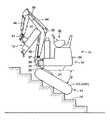
図1〜図7に示す自走式作業機械10は、下部走行体14と上部作業体16とを備えている。  A self-propelledworking machine 10 shown in FIGS. 1 to 7 includes alower traveling body 14 and an upper workingbody 16.

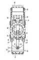
前記下部走行体14は、図4及び図5に示す車体フレーム18と、その左右両側に設けられた走行用のクローラ20L,20Rとを備えている。これらのクローラ20L,20Rは、前後に配される図略の鉄輪と、これらの鉄輪の間に掛け渡されるクローラベルトとを有し、側方からみて前後方向に延びる略小判状をなしている。  The lower travelingbody 14 includes avehicle body frame 18 shown in FIGS. 4 and 5 and travelingcrawlers 20L and 20R provided on the left and right sides thereof. These crawlers 20L and 20R have iron rings (not shown) arranged in the front and rear, and crawler belts stretched between these iron rings, and have a substantially oval shape extending in the front-rear direction when viewed from the side. .

前記車体フレーム18にはその進行方向前端に設けられた左右方向の支軸22回りに起伏フレーム24の前端が回動可能に連結され、この起伏フレーム24上に前記図1〜図3に示す上部作業体16が搭載されている。  A front end of aundulation frame 24 is rotatably connected to thebody frame 18 around ahorizontal support shaft 22 provided at a front end in the traveling direction, and the upper portion shown in FIGS. Awork body 16 is mounted.

図4及び図5に示すように、前記起伏フレーム24と前記車体フレーム18との間には、油圧シリンダからなる上部作業体操作シリンダ26が設けられている。この上部作業体操作シリンダ26の一方の端部は左右方向のピン25を介して前記車体フレーム18の前端部に回動可能に枢支され、他方の端部は前記起伏フレーム24の前後方向略中間部に左右方向のピン27を介して回動可能に連結されており、この上部作業体操作シリンダ26の伸縮によって前記起伏フレーム24が起伏し、この起伏フレーム24上に搭載されている前記上部作業体16が図3に示すような通常位置と図1及び図2に示すような傾斜位置とに切換えられるようになっている。  As shown in FIGS. 4 and 5, an upper workingbody operating cylinder 26 made of a hydraulic cylinder is provided between the hoistingframe 24 and thevehicle body frame 18. One end of the upper workbody operating cylinder 26 is pivotally supported on the front end of thebody frame 18 via apin 25 in the left-right direction, and the other end is substantially in the front-rear direction of the hoistingframe 24. The upper andlower frames 24 are undulated by the expansion and contraction of the upper workbody operation cylinder 26 and are mounted on theundulation frame 24. Thework body 16 is switched between a normal position as shown in FIG. 3 and an inclined position as shown in FIGS. 1 and 2.

ここで、前記通常位置は、前記下部走行体14に対して前記上部作業体16が略水平な姿勢で支持される位置であり、この位置で通常走行が可能となる。これに対して前記傾斜位置は、前記下部走行体14に対して前記上部作業体16が所定角度θだけ前下がりに傾斜した位置であり、その所定角度θはこの自走式作業機械10の昇降が想定される傾斜路(図例では階段28)の傾斜角度と略同等の角度(図例では約45°)に設定されている。  Here, the normal position is a position where the upper workingbody 16 is supported in a substantially horizontal posture with respect to the lower travelingbody 14, and normal traveling is possible at this position. On the other hand, the inclined position is a position where the upper workingbody 16 is inclined forward and downward by a predetermined angle θ with respect to the lower travelingbody 14, and the predetermined angle θ is an elevation of the self-propelled workingmachine 10. Is set to an angle (about 45 ° in the example) substantially equal to the inclination angle of the ramp (step 28 in the example).

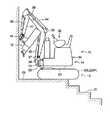
なお、図1〜図3のうち、図1は前記自走式作業機械10が階段28上を昇降している状態を示し、図2は後に詳述するように前記自走式作業機械10が前記階段28の上端に続く上側目標地(同図の例では踊り場29)に乗り上げる直前の状態を示し、図3は前記自走式作業機械10が前記踊り場29に完全に乗り上げた後の状態を示している。  1 to 3, FIG. 1 shows a state where the self-propelled workingmachine 10 is moving up and down on thestairs 28, and FIG. 2 shows the self-propelled workingmachine 10 as described in detail later. FIG. 3 shows a state immediately before riding on the upper target site (the landing 29 in the example of the figure) following the upper end of thestaircase 28, and FIG. 3 shows a state after the self-propelled workingmachine 10 has completely climbed on thelanding 29. Show.

なお、本発明に係る「上側目標地」は前記踊り場29に限らず、例えば急斜面の上端に続く広い平坦面であってもよい。  The “upper destination” according to the present invention is not limited to the landing 29 but may be a wide flat surface that continues to the upper end of a steep slope, for example.

前記起伏フレーム24は、その前後方向の略中間部に図4及び図5に示すような旋回軸受部30を有しており、この旋回軸受部30上に前記図1〜図3に示す上部作業体16が鉛直軸回りに旋回可能に支持されている。  The undulatingframe 24 has aslewing bearing portion 30 as shown in FIGS. 4 and 5 at a substantially middle portion in the front-rear direction, and the upper work shown in FIGS. 1 to 3 on theslewing bearing portion 30. Thebody 16 is supported so as to be able to turn around a vertical axis.

この上部作業体16は、運転席32が搭載された旋回本体部34を備え、この旋回本体部34の前端に垂直軸35回りに回動(スイング)可能となるようにブーム支持部材36が設けられている。そして、このブーム支持部材36に左右方向の軸37回りに回動可能(起伏可能)となるようにブーム38が取付けられ、このブーム38の先端部に左右方向の軸39回りに回動可能となるようにアーム40が取付けられており、このアーム40の先端部に同じく左右方向の軸回りに回動可能となるように前記スクレーパー12が設けられている。  The upper workingbody 16 includes a turningbody 34 on which a driver'sseat 32 is mounted, and aboom support member 36 is provided at the front end of the turningbody 34 so as to be rotatable (swing) around avertical axis 35. It has been. Aboom 38 is attached to theboom support member 36 so as to be rotatable (can be raised and lowered) about a left-right axis 37, and can be rotated about a left-right axis 39 at the tip of theboom 38. Anarm 40 is attached so that thescraper 12 is provided at the tip of thearm 40 so as to be rotatable about a left-right axis.

なお、前記ブーム38の起伏、このブーム38に対する前記アーム40の回動、及びこのアーム40に対する前記スクレーパー12の回動は、それぞれ、油圧シリンダからなるブームシリンダ42、アームシリンダ44、及びアタッチメントシリンダ46の伸縮により実現される。  Theboom 38 is raised and lowered, thearm 40 is rotated with respect to theboom 38, and thescraper 12 is rotated with respect to thearm 40. Theboom cylinder 42, thearm cylinder 44, and theattachment cylinder 46 are hydraulic cylinders, respectively. Realized by expansion and contraction.

この自走式作業機械10の特徴として、前記車体フレーム18の前後部には、それぞれ、図4〜図6に示すような前側張出し部材50及び後側張出し部材52が取付けられている。これらの張出し部材50,52は、図4に実線で示す格納位置と、同図に二点鎖線で示す張出し位置とに切換可能となっている。  As a feature of the self-propelled workingmachine 10, afront projecting member 50 and arear projecting member 52 as shown in FIGS. 4 to 6 are attached to the front and rear portions of thebody frame 18, respectively. Theseoverhang members 50 and 52 can be switched between a storage position indicated by a solid line in FIG. 4 and an overhang position indicated by a two-dot chain line in FIG.

このうち、前側張出し部材50は、その張出しによって、自走式作業機械10が前記階段28から踊り場29へ静かに乗り上げるのを援助するものであって、本発明に係る「張出し部材」に相当するものである。これに対して、後側張出し部材52は、その張出しによって、下部走行体14がその左側クローラ20Lの前端または右側クローラ20Rの前端を中心として小回り旋回することを実現するためのものであって、本発明では特に必須の要素ではない。  Among these, the frontside overhang member 50 assists the self-propelled workingmachine 10 to silently run from thestairs 28 to thelanding 29 by the overhang, and corresponds to the “overhang member” according to the present invention. Is. On the other hand, therear projecting member 52 is for realizing that the lower travelingbody 14 turns slightly around the front end of theleft crawler 20L or the front end of theright crawler 20R by the projecting, It is not a particularly essential element in the present invention.

前記前側張出し部材50は、回動アーム53と、この回動アーム53の端部に取付けられる転動体である左右一対のキャスター54とを備えている。  The front projectingmember 50 includes arotating arm 53 and a pair of left andright casters 54 that are rolling elements attached to the end of therotating arm 53.

前記回動アーム53は、左右一対の回動側板56と、キャスター支持板58とを備えている。前記両回動側板56は、前記車体フレーム18の前半部分に回動可能に取付けられ、これらの回動側板56同士を連結するように前記キャスター支持板58が設けられている。詳しくは、前記両回動側板56の回動基端部が、前記車体フレーム18の前半部に設けられた左右方向の支軸60を中心として回動可能となるように当該支軸60に枢支され、回動先端部同士が左右方向に延びる前記キャスター支持板58によって相互連結されている。  Thepivot arm 53 includes a pair of left and rightpivot side plates 56 and acaster support plate 58. Both therotating side plates 56 are rotatably attached to the front half portion of thevehicle body frame 18, and thecaster support plate 58 is provided so as to connect theserotating side plates 56 to each other. Specifically, the pivot base end portions of both thepivot side plates 56 are pivoted on thepivot shaft 60 so as to be pivotable about apivot shaft 60 provided in the front half of thebody frame 18 in the left-right direction. The pivot tip portions are supported by thecaster support plate 58 extending in the left-right direction.

前記各キャスター54は、前記キャスター支持板58の下側にキャスターブラケット62を介して取付けられている。これらのキャスターブラケット62は、前記キャスター支持板58の板厚方向に延びる図略の軸回りに回転可能となるように当該キャスター支持板58に取付けられ、かつ、前記キャスター54を前記キャスター支持板58と平行な方向の軸64を介して回転可能に保持している。  Each of thecasters 54 is attached to the lower side of thecaster support plate 58 via acaster bracket 62. Thesecaster brackets 62 are attached to thecaster support plate 58 so as to be rotatable about an unillustrated axis extending in the thickness direction of thecaster support plate 58, and thecaster 54 is attached to thecaster support plate 58. It is rotatably held via anaxis 64 in a direction parallel to the axis.

前記回動側板56と車体フレーム18との間には、油圧シリンダからなる前側張出し部材操作シリンダ66が介設され、この前側張出し部材操作シリンダ66の伸縮によって前記前側張出し部材50が前記格納位置と前記張出し位置との間で回動操作されるようになっている。  A front projectingmember operating cylinder 66 made of a hydraulic cylinder is interposed between therotating side plate 56 and thevehicle body frame 18, and the front projectingmember 50 is brought into the retracted position by expansion and contraction of the front projectingmember operating cylinder 66. Rotation operation is performed between the overhang positions.

詳しくは、前記車体フレーム18においてその前後方向中間位置よりも後方の部分に当該車体フレーム18の下面から下方に突出するシリンダブラケット68が設けられ、このシリンダブラケット68に前記前側張出し部材操作シリンダ66のへッド側端部が左右方向のピン70を介して相対回動可能に連結されるとともに、この前側張出し部材操作シリンダ66のロッド側端部が左右方向のピン72を介して前記両回動側板56の回動基端部近傍部位に相対回動可能に連結されている。  Specifically, acylinder bracket 68 that protrudes downward from the lower surface of thevehicle body frame 18 is provided at a portion of thevehicle body frame 18 that is behind the intermediate position in the front-rear direction, and thecylinder bracket 68 is provided with a front extensionmember operation cylinder 66. The head-side end portion is connected to the left andright pins 70 so as to be relatively rotatable, and the rod-side end portion of the front projectingmember operating cylinder 66 is turned to the both directions via the left and right pins 72. Theside plate 56 is connected to the vicinity of the rotation base end portion so as to be relatively rotatable.

そして、前記前側張出し部材操作シリンダ66が伸長した状態で、図4の実線に示すように前側張出し部材50全体が側方からみて前記クローラ20L,20Rの外形の内側に収まる格納位置に収められる一方、前記前側張出し部材操作シリンダ66が収縮することにより同図二点鎖線に示すように前記前側張出し部材50が前記クローラ20L,20Rの下面から大きく突出する張出し位置まで張出されるようになっている。その張出し量は、前記図2に示すように、自走式作業機械10が踊り場29に到達する直前の到達直前位置において、前記張出し位置にある前側張出し部材50のキャスター54が前記踊り場29に着地するような張出し量もしくはそれに近い張出し量に設定されている。  Then, in a state where the front projectingmember operating cylinder 66 is extended, the entirefront projecting member 50 is stored in a storage position that fits inside the outer shape of thecrawlers 20L and 20R as seen from the side as shown by a solid line in FIG. When the front projectingmember operating cylinder 66 contracts, thefront projecting member 50 is projected to a projecting position that largely protrudes from the lower surfaces of thecrawlers 20L and 20R, as indicated by a two-dot chain line in FIG. . As shown in FIG. 2, the amount of overhang is such that thecaster 54 of thefront overhang member 50 in the overhang position lands on the landing 29 just before the self-propelled workingmachine 10 reaches thelanding 29. The overhang amount is set at or near the overhang amount.

なお、本発明において前記格納位置は少なくとも下部走行体14の通常走行を可能にする位置であればよく、必ずしもクローラ20L,20Rの外形内に収められていなくてもよい。  In the present invention, the storage position may be at least a position that allows the lower travelingbody 14 to normally travel, and does not necessarily have to be stored in the outer shape of thecrawlers 20L and 20R.

一方、前記後側張出し部材52は、前記前側張出し部材50と同様、回動アーム73と、この回動アーム73の端部に取付けられる転動体である左右一対のキャスター74とを備えている。  On the other hand, therear projecting member 52 includes arotating arm 73 and a pair of left andright casters 74 which are rolling elements attached to the end of therotating arm 73, as with the front projectingmember 50.

前記回動アーム73は、左右一対の回動側板76と、キャスター支持板78とを備えている。前記両回動側板76は、前記車体フレーム18の後端部に回動可能に取付けられ、これらの回動側板76同士を連結するように前記キャスター支持板78が設けられている。詳しくは、前記車体フレーム18の後端から後方にブラケット79が突設され、このブラケット79に前記両回動側板76の回動基端部が左右方向の支軸80を中心として回動可能となるように当該支軸80に枢支され、両回動側板76の回動先端部同士が左右方向に延びる前記キャスター支持板78によって相互連結されている。  Thepivot arm 73 includes a pair of left and rightpivot side plates 76 and acaster support plate 78. Both therotation side plates 76 are rotatably attached to the rear end portion of thevehicle body frame 18, and thecaster support plate 78 is provided so as to connect therotation side plates 76 to each other. Specifically, abracket 79 projects rearward from the rear end of thevehicle body frame 18, and the rotation base end portions of the bothrotation side plates 76 can rotate about thesupport shaft 80 in the left-right direction. The pivot tips of thepivot side plates 76 are pivotally supported so as to be connected to each other by thecaster support plates 78 extending in the left-right direction.

前記各キャスター74は、前記キャスター54と同様にして、前記キャスター支持板78の下側にキャスターブラケット82を介して取付けられている。すなわち、左右のキャスターブラケット82は、前記キャスター支持板78の板厚方向に延びる図略の軸回りに回転可能となるように当該キャスター支持板78に取付けられ、かつ、前記キャスター74を前記キャスター支持板78と平行な方向の軸84を介して回転可能に保持している。  Eachcaster 74 is attached to the lower side of thecaster support plate 78 through acaster bracket 82 in the same manner as thecaster 54. That is, the left andright caster brackets 82 are attached to thecaster support plate 78 so as to be rotatable about an unillustrated axis extending in the thickness direction of thecaster support plate 78, and thecaster 74 is supported by the caster. It is rotatably held via anaxis 84 in a direction parallel to theplate 78.

前記回動側板76と車体フレーム18との間にも、油圧シリンダからなる後側張出し部材操作シリンダ86が介設され、この後側張出し部材操作シリンダ86の伸縮によって前記後側張出し部材52が前記格納位置と前記張出し位置との間で回動操作されるようになっている。  A rear projectingmember operating cylinder 86 made of a hydraulic cylinder is also interposed between therotating side plate 76 and thevehicle body frame 18, and therear projecting member 52 is moved by the expansion and contraction of the rear projectingmember operating cylinder 86. A rotation operation is performed between the storage position and the overhang position.

詳しくは、前記後側張出し部材操作シリンダ86のへッド側端部が前記シリンダブラケット68において前記ピン70よりも僅かに後側に位置する左右方向のピン90を介して当該シリンダブラケット68に相対回動可能に連結されるとともに、この後側張出し部材操作シリンダ86のロッド側端部が左右方向のピン92を介して前記両回動側板76の回動基端部近傍部位に相対回動可能に連結されている。そして、前記後側張出し部材操作シリンダ86が伸長した状態で、図4の実線に示すように後側張出し部材52全体が側方からみて前記クローラ20L,20Rの外形の内側に収まる格納位置に収められる一方、前記後側張出し部材操作シリンダ86が収縮することにより同図二点鎖線に示すように前記後側張出し部材52が前記クローラ20L,20Rの下面から下方に突出する張出し位置まで張出されるようになっている。  Specifically, the head side end portion of the rear extensionmember operating cylinder 86 is relative to thecylinder bracket 68 via a left andright pin 90 positioned slightly rearward of thepin 70 in thecylinder bracket 68. The rod-side end of the rear-side extendingmember operating cylinder 86 can be relatively rotated to a portion in the vicinity of the rotation base end portions of the both rotation-side plates 76 via apin 92 in the left-right direction. It is connected to. Then, in a state where the rear side extensionmember operating cylinder 86 is extended, the rearside extension member 52 as a whole is stored in a retracted position that fits inside the outer shape of thecrawlers 20L and 20R as seen from the side as shown by the solid line in FIG. On the other hand, when the rear side extensionmember operating cylinder 86 contracts, the rearside extension member 52 is extended to the extension position protruding downward from the lower surfaces of thecrawlers 20L and 20R, as shown by the two-dot chain line in FIG. It is like that.

この後側張出し部材52の張出し量は、前記前側張出し部材50の張出し量よりも小さく、かつ、その張出しによって前記キャスター54の転動に伴う下部走行体14の小回り旋回が可能となる量に設定されている。すなわち、この後側張出し部材52が張出し位置にある状態で、例えば右側のクローラ20Rを停止させたまま左側のクローラ20Lを前進方向に作動させることにより、当該右側のクローラ20Rの前端位置を右側旋回中心として下部走行体14が右向きに小回り旋回し、逆に左側のクローラ20Lを停止させたまま右側のクローラ20Rを前進方向に作動させることにより、当該左側のクローラ20Lの前端位置を左側旋回中心として下部走行体14が左向きに小回り旋回するようになっている。  The overhang amount of the rearside overhanging member 52 is set to an amount that is smaller than the overhanging amount of the frontside overhanging member 50 and that allows theundercarriage 14 to turn in a small direction as thecaster 54 rolls. Has been. That is, in the state in which the rearside extension member 52 is in the extension position, for example, by operating theleft crawler 20L in the forward direction while theright crawler 20R is stopped, the front end position of theright crawler 20R is turned to the right. Thelower traveling body 14 turns slightly to the right as the center, and conversely, theleft crawler 20L is operated in the forward direction while theleft crawler 20L is stopped, so that the front end position of theleft crawler 20L is the left turning center. Thelower traveling body 14 is turned slightly to the left.

図7は、前記小回り旋回を利用して前記踊り場29で自走式作業機械10全体を180°転回させる例を示したものであり、この例では、左側クローラ20Lのみの作動によって右側クローラ20Rの前端部位を旋回中心Oとして小回り旋回を繰り返すことにより、狭い踊り場29内での転回が可能となっている。  FIG. 7 shows an example in which the entire self-propelledwork machine 10 is turned 180 ° at thelanding 29 using the small turn, and in this example, only theleft crawler 20L is operated by theleft crawler 20L. By repeating the small turn with the front end portion as the turning center O, the turning within thenarrow landing 29 is possible.

また、この実施の形態では、前側張出し部材50の張出し量が後側張出し部材52の張出し量よりも大きい点に鑑み、両張出し部材50,52の操作手段である張出し部材操作シリンダ66,86のへッド側端部が連結されるシリンダブラケット68の位置を下部走行体14の前後方向中心位置よりも後側にシフトさせて両操作シリンダ66,86の十分なシリンダストロークを確保するように配慮がなされている。さらに、後側張出し部材52については、その回動側板76の形状をその途中部分で下向きに屈曲する形状とすることにより、前記後側張出し部材操作シリンダ86のシリンダストロークを十分に確保しながら、前記格納位置にある後側張出し部材52全体が側方からみてクローラ20L,20Rの外形の内側に収められるように設計がなされている。  Further, in this embodiment, in consideration of the fact that the extension amount of thefront extension member 50 is larger than the extension amount of therear extension member 52, the extensionmember operation cylinders 66 and 86 that are the operation means of the bothextension members 50 and 52 are provided. Consideration is given to ensure sufficient cylinder stroke of both operatingcylinders 66 and 86 by shifting the position of thecylinder bracket 68 to which the head side end is coupled to the rear side of the center position in the front-rear direction of the lower travelingbody 14. Has been made. Further, with respect to therear extension member 52, by making the shape of therotating side plate 76 bent downward at the middle portion thereof, while sufficiently securing the cylinder stroke of the rear extensionmember operation cylinder 86, The entirerear projecting member 52 in the retracted position is designed to be accommodated inside the outer shape of thecrawlers 20L and 20R when viewed from the side.

また、前記キャスター54,74の転動面については、当該キャスター54,74及びキャスター保持部材62,82が容易に回転(キャスター54,74の向きを変えるような回転)をするように幅方向中央部が径方向外側に膨らむ面とされている。さらに、これらのキャスター54,74の保護のため、各回動アーム53,73の外側端部には泥除け板55,75が取付けられている。  The rolling surfaces of thecasters 54 and 74 are centered in the width direction so that thecasters 54 and 74 and thecaster holding members 62 and 82 can be easily rotated (rotation that changes the direction of thecasters 54 and 74). The part is a surface that swells radially outward. Further,mudguard plates 55 and 75 are attached to the outer end portions of the respectiverotating arms 53 and 73 in order to protect thesecasters 54 and 74.

なお、各張出し部材50,52に設けられる転動体としては、前記キャスター54,74の他、球体を自由回転可能となるように回動アーム53,73に保持するようにしてもよい。また、前側張出し部材50については、その着地部分が踊り場29上を滑り易い形状にしておけば、転動体を適宜省略することも可能である。  In addition to thecasters 54 and 74, the rolling members provided on theoverhang members 50 and 52 may be held on the rotatingarms 53 and 73 so as to be freely rotatable. In addition, as for the front projectingmember 50, if the landing portion has a shape that allows easy sliding on thelanding 29, the rolling elements can be appropriately omitted.

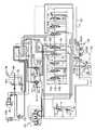
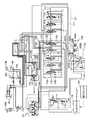
次に、前記各油圧シリンダ及び図略の走行モータや旋回モータを作動させるために自走式作業機械10に搭載される流体圧回路(図例では油圧回路)を図8〜図10を参照しながら説明する。  Next, referring to FIGS. 8 to 10, fluid pressure circuits (hydraulic circuits in the illustrated example) mounted on the self-propelledwork machine 10 to operate the hydraulic cylinders and the travel motors and swing motors (not shown) will be described. While explaining.

この油圧回路は、その油圧供給源として、油圧ポンプからなるメインポンプ101,102及びパイロット用ポンプ104を備えている。これらのポンプ101,102,104はエンジン100の出力軸に連結され、その駆動により作動油を吐出する。  The hydraulic circuit includesmain pumps 101 and 102 including a hydraulic pump and apilot pump 104 as a hydraulic pressure supply source. Thesepumps 101, 102, 104 are connected to the output shaft of theengine 100, and discharge hydraulic fluid when driven.

前記両メインポンプ101,102は、自走式作業機械10に搭載される各油圧アクチュエータに作動油を供給する。具体的には、上述の上部作業体操作シリンダ26、ブームシリンダ42、アームシリンダ44、アタッチメントシリンダ46、及び両張出し部材操作シリンダ66,86の他、左右クローラ20L,20Rのスパンを拡縮させるスパンシリンダ106、さらに、図示はしていないが左右クローラ20L,20Rをそれぞれ作動させるための左右走行モータ、上部作業体16を旋回させる旋回モータ、ブーム支持部材36を左右に回動させるためのスイングシリンダ等に作動油を供給する。  Both themain pumps 101 and 102 supply hydraulic oil to each hydraulic actuator mounted on the self-propelledwork machine 10. Specifically, in addition to the upper workbody operation cylinder 26, theboom cylinder 42, thearm cylinder 44, theattachment cylinder 46, and the both overhangmember operation cylinders 66 and 86, the span cylinder that expands and contracts the spans of the left andright crawlers 20L and 20R. 106, although not shown, a left and right traveling motor for operating the left andright crawlers 20L and 20R, a turning motor for turning the upper workingbody 16, a swing cylinder for turning theboom support member 36 to the left and right, etc. Supply hydraulic oil to

前記メインポンプ101,102と前記各油圧アクチュエータとの間には、制御弁ブロック110が介在している。この制御弁ブロック110は、前記メインポンプ101から供給油路121を通じて供給される作動油をタンク108に導くセンターバイパス流路111と、前記メインポンプ102から供給油路122を通じて供給される作動油をタンク108に導くセンターバイパス流路112とを有するとともに、これらのセンターバイパス流路111,112に沿って複数の制御弁が直列に配されている。  Acontrol valve block 110 is interposed between themain pumps 101 and 102 and the hydraulic actuators. Thecontrol valve block 110 includes acenter bypass passage 111 that guides hydraulic oil supplied from themain pump 101 through thesupply oil passage 121 to thetank 108, and hydraulic oil supplied from themain pump 102 through the supply oil passage 122. Acenter bypass passage 112 leading to thetank 108 and a plurality of control valves are arranged in series along thecenter bypass passages 111 and 112.

具体的に、前記センターバイパス流路111側には、前記アームシリンダ44に接続されるアーム制御弁113と、前記旋回モータに接続される旋回制御弁114と、左走行モータに接続される左走行制御弁115とが配列され、前記センターバイパス流路112側には、前記アタッチメントシリンダ46に接続されるアタッチメント制御弁116と、前記ブームシリンダ42に接続されるブーム制御弁117と、前記スイングシリンダに接続されるスイング制御弁118と、右走行モータに接続される右走行制御弁119と、前記スパンシリンダ106、上部作業体操作シリンダ26、及び前後張出し部材操作シリンダ66,86について共通して設けられる共通制御弁120とが配列されている。  Specifically, on the side of thecenter bypass passage 111, anarm control valve 113 connected to thearm cylinder 44, a swing control valve 114 connected to the swing motor, and a left travel connected to the left travel motor. Thecontrol valve 115 is arranged, and on thecenter bypass passage 112 side, anattachment control valve 116 connected to theattachment cylinder 46, aboom control valve 117 connected to theboom cylinder 42, and the swing cylinder Theswing control valve 118 to be connected, the righttravel control valve 119 connected to the right travel motor, thespan cylinder 106, the upper workbody operation cylinder 26, and the front and rear extensionmember operation cylinders 66 and 86 are provided in common. Acommon control valve 120 is arranged.

これらの制御弁113〜120は、流量調節機能をもった3位置方向切換弁(スイング制御弁117は手動切換弁、それ以外の制御弁は油圧パイロット切換弁)により構成されており、その中立位置(図では中段位置)では、前記メインポンプ101またはメインポンプ102から供給される作動油をそのままタンク108側にバイパスさせる一方、当該中立位置から前記パイロット用ポンプ104のパイロット圧によるパイロット操作または手動操作を受けると、その操作量に見合った流量で、接続されている油圧アクチュエータに前記作動油を導くものとなっている。  Thesecontrol valves 113 to 120 are each constituted by a three-position direction switching valve having a flow rate adjusting function (theswing control valve 117 is a manual switching valve, and the other control valves are hydraulic pilot switching valves). In the middle position in the figure, the hydraulic oil supplied from themain pump 101 or themain pump 102 is bypassed to thetank 108 side as it is, while the pilot operation or the manual operation by the pilot pressure of thepilot pump 104 is performed from the neutral position. The hydraulic fluid is guided to the connected hydraulic actuator at a flow rate corresponding to the operation amount.

前記パイロット用ポンプ104と各走行制御弁115,118との間には、走行リモコン弁124が介在している。この走行リモコン弁124は、図11(a)(b)に示すような左右走行レバー125L,125Rを有し、その走行レバーに対応する走行制御弁に対し、その操作方向に対応するパイロット部にその操作量に対応する大きさのパイロット圧を導くように構成されている。従って、この走行リモコン弁124の走行レバー125L,12Rを操作することにより、その操作量に見合った速度で左右クローラ20L,20Rをそれぞれ走行動作させることが可能となっている。  A travelremote control valve 124 is interposed between thepilot pump 104 and thetravel control valves 115 and 118. The travelremote control valve 124 has left and right travel levers 125L and 125R as shown in FIGS. 11 (a) and 11 (b), and a travel control valve corresponding to the travel lever serves as a pilot portion corresponding to the operation direction. A pilot pressure having a magnitude corresponding to the operation amount is introduced. Therefore, by operating the travel levers 125L and 12R of the travelremote control valve 124, the left andright crawlers 20L and 20R can be traveled at a speed corresponding to the operation amount.

また、この実施の形態では、前記供給油路121,122からタンク108側にそれぞれ逃がし油路126A,126Bが分岐しており、各逃がし油路126A,126Bには流量調整弁127A,127B及び切換弁128A,128Bがそれぞれ直列に配されている。  Further, in this embodiment,relief oil passages 126A and 126B branch from thesupply oil passages 121 and 122 to thetank 108 side, respectively, and flowrelief valves 127A and 127B and switching are provided in therelief oil passages 126A and 126B, respectively.Valves 128A and 128B are arranged in series, respectively.

両切換弁128A,128Bは、前記逃がし油路126A,126Bをそれぞれ遮断する遮断位置(図の左位置)と同油路126A,126Bを連通する逃がし位置(図の右位置)とに切換可能であり、これらの遮断位置と逃がし位置とに互いに連動して切換操作されるようになっている。従って、両切換弁128A,128Bが前記遮断位置に切換えられたときには、メインポンプ101,102の吐出油全量が前記制御弁ブロック110に送られることにより、前記走行レバーの操作量に対応する正規の作動油供給流量及び正規の走行速度が確保される一方、前記両切換弁128A,128Bが前記逃がし位置に切換えられたときには、その逃がし量分だけ作動油供給流量が減り、走行レバーをフル操作したときの走行速度すなわち最高速度が制限されるようになっている。  Both switchingvalves 128A and 128B can be switched between a shut-off position (left position in the figure) for blocking theescape oil paths 126A and 126B and a release position (right position in the figure) communicating with theoil paths 126A and 126B. There is a switching operation in conjunction with the blocking position and the escape position. Therefore, when both the switchingvalves 128A and 128B are switched to the shut-off position, the total amount of oil discharged from themain pumps 101 and 102 is sent to thecontrol valve block 110, so that the normal amount corresponding to the operation amount of the travel lever is reached. While the hydraulic oil supply flow rate and the normal running speed are ensured, when the switchingvalves 128A and 128B are switched to the escape position, the hydraulic oil supply flow rate is reduced by the relief amount and the travel lever is fully operated. The traveling speed at the time, that is, the maximum speed is limited.

次に、前記メインポンプ102から前記共通制御弁120を経由してのシリンダ106,26,66,86に対する油圧供給系統について説明する。  Next, a hydraulic pressure supply system from themain pump 102 to thecylinders 106, 26, 66, 86 via thecommon control valve 120 will be described.

前記共通制御弁120は、パイロット部131,132を有し、これらのパイロット部131,132と前記パイロット用ポンプ104との間にはそれぞれ電磁切換弁133,134が設けられている。各電磁切換弁133,134は、それぞれソレノイドb1,b2を有し、当該ソレノイドb1,b2が通電されていないオフ状態では前記パイロット用油を前記パイロット部131,132に導いてパイロット圧を発生させる一方、当該ソレノイドb1,b2が通電されたオン状態では前記パイロット用ポンプ104からのパイロット用油をタンク108に逃がすように構成されている。  Thecommon control valve 120 haspilot portions 131 and 132, andelectromagnetic switching valves 133 and 134 are provided between thepilot portions 131 and 132 and thepilot pump 104, respectively. Theelectromagnetic switching valves 133 and 134 have solenoids b1 and b2, respectively. When the solenoids b1 and b2 are not energized, the pilot oil is guided to thepilot parts 131 and 132 to generate a pilot pressure. On the other hand, when the solenoids b1 and b2 are energized, the pilot oil from thepilot pump 104 is allowed to escape to thetank 108.

共通制御弁120は、両パイロット部131,132にパイロット圧が供給されず、あるいは同等のパイロット圧が供給されたときには、中立位置(センターバイパス位置)を保持する一方、パイロット部131にのみパイロット圧が供給されたときにはポンプ吐出油を油路137に導いて油路138をタンク108側に接続する位置(図の下段位置)に切換えられ、パイロット部132にのみパイロット圧が供給されたときにはポンプ吐出油を油路138に導いて油路137をタンク108側に接続する位置(図の上段位置)に切換えられる。  Thecommon control valve 120 maintains a neutral position (center bypass position) when pilot pressure is not supplied to bothpilot parts 131 and 132 or when equivalent pilot pressure is supplied, while pilot pressure is applied only to thepilot part 131. Is supplied to theoil passage 137 and switched to a position (lower position in the figure) where theoil passage 138 is connected to thetank 108 side. When pilot pressure is supplied only to thepilot section 132, the pump discharge oil is discharged. The oil is guided to theoil passage 138 and switched to the position (the upper position in the figure) where theoil passage 137 is connected to thetank 108 side.

前記油路137は2つの分岐油路141,142に分岐し、前記油路138は2つの分岐油路144,145に分岐している。その下流側には、前記スパンシリンダ106または上部作業体操作シリンダ26を作動状態と停止状態とに切換えるための電磁切換弁(上部作業体側切換弁)148と、前記前側張出し部材操作シリンダ66または後側張出し部材操作シリンダ86を作動状態と停止状態とに切換えるための電磁切換弁(張出し部材側切換弁)147と、手動操作によって前記スパンシリンダ106と上部作業体操作シリンダ26とを択一的に作動可能状態に切換えるための選択弁150と、手動操作によって前記前側張出し部材操作シリンダ66と後側張出し部材操作シリンダ86とを択一的に作動可能状態に切換えるための前後切換弁152,154とが設けられている。  Theoil passage 137 branches into twobranch oil passages 141 and 142, and theoil passage 138 branches into twobranch oil passages 144 and 145. On the downstream side thereof, an electromagnetic switching valve (upper working body side switching valve) 148 for switching thespan cylinder 106 or the upper workingbody operating cylinder 26 between an operating state and a stopped state, and the front projectingmember operating cylinder 66 or the rear An electromagnetic switching valve (overhanging member side switching valve) 147 for switching the side extendingmember operating cylinder 86 between an operating state and a stopped state, and thespan cylinder 106 and the upper workbody operating cylinder 26 are alternatively selected by manual operation. Aselection valve 150 for switching to an operable state, and front /rear switching valves 152 and 154 for switching the front-side extendingmember operating cylinder 66 and the rear-side extendingmember operating cylinder 86 alternatively to an operable state by manual operation. Is provided.

具体的に、前記分岐油路141,142,144,145のうち、分岐油路141は電磁切換弁147を通じて前記前後切換弁152に至っており、この手動切換弁152は、その手動操作により、前記分岐油路141を前側張出し部材操作シリンダ66のへッド側室に接続する前側選択位置(図の下側位置)と後側張出し部材操作シリンダ86のへッド側室に接続する後側選択位置(図の上側位置)とに択一的に切換えられる。また、分岐油路142は、電磁切換弁148を通じて前記選択弁150に至っており、この選択弁150は、その手動操作により、前記分岐油路142を前記スパンシリンダ106のロッド側室に接続するスパン選択位置(図の左側位置)と前記各上部作業体操作シリンダ26のロッド側室に接続する上部作業体操作選択位置(図の右側位置)とに択一的に切換えられる。  Specifically, of thebranch oil passages 141, 142, 144, and 145, thebranch oil passage 141 reaches the front /rear switching valve 152 through anelectromagnetic switching valve 147, and themanual switching valve 152 is operated by the manual operation. A front selection position (lower position in the figure) for connecting thebranch oil passage 141 to the head side chamber of the front extensionmember operation cylinder 66 and a rear selection position for connecting to the head side chamber of the rear extension member operation cylinder 86 ( (The upper position in the figure). Further, thebranch oil passage 142 reaches theselection valve 150 through anelectromagnetic switching valve 148, and theselection valve 150 manually selects the span to connect thebranch oil passage 142 to the rod side chamber of thespan cylinder 106. The position is selectively switched between the position (left position in the figure) and the upper work body operation selection position (right position in the figure) connected to the rod side chamber of each upper workbody operation cylinder 26.

一方、前記分岐油路144は、前記電磁切換弁147を通じて前記前後切換弁154に至っている。この前後切換弁154は、その手動操作により、前記分岐油路144を前記前側張出し部材操作シリンダ66のロッド側室に接続する前側選択位置(図の下側位置)と後側張出し部材操作シリンダ86のロッド側室に接続する後側選択位置(図の上側位置)とに択一的に切換えられる。また、前記分岐油路145は、前記電磁切換弁148を通じて前記各上部作業体操作シリンダ26のへッド側室と前記スパンシリンダ106のへッド側室とに至っている。  On the other hand, thebranch oil passage 144 reaches the front /rear switching valve 154 through theelectromagnetic switching valve 147. The front /rear switching valve 154 is manually operated so that thebranch oil passage 144 is connected to the rod side chamber of the front extensionmember operation cylinder 66 at the front selection position (lower position in the figure) and the rear extensionmember operation cylinder 86. It is alternatively switched to a rear selection position (upper position in the figure) connected to the rod side chamber. Further, thebranch oil passage 145 reaches the head side chamber of each upper workbody operating cylinder 26 and the head side chamber of thespan cylinder 106 through theelectromagnetic switching valve 148.

前記電磁切換弁147は、ソレノイドa1を有し、このソレノイドa1が通電していないオフ状態では前記分岐油路141,144をともに遮断する閉弁位置(図の右側位置)に切換えられる一方、前記ソレノイドa1が通電しているオン状態では前記分岐油路141,144をともに開通する開弁位置(図の左側位置)に切換えられる。同様に、前記電磁切換弁148は、ソレノイドa2を有し、このソレノイドa2が通電していないオフ状態では前記分岐油路142,145をともに遮断する閉弁位置(図の右側位置)に切換えられる一方、前記ソレノイドa2が通電しているオン状態では前記分岐油路142,145をともに開通する開弁位置(図の左側位置)に切換えられる。  Theelectromagnetic switching valve 147 has a solenoid a1, and when the solenoid a1 is not energized, theelectromagnetic switching valve 147 is switched to a valve closing position (right side position in the figure) that shuts off both thebranch oil passages 141 and 144. In the ON state in which the solenoid a1 is energized, the valve is switched to the valve opening position (left position in the figure) where both thebranch oil passages 141 and 144 are opened. Similarly, theelectromagnetic switching valve 148 has a solenoid a2, and when the solenoid a2 is not energized, theelectromagnetic switching valve 148 is switched to a valve closing position (right position in the figure) that shuts off both thebranch oil passages 142 and 145. On the other hand, in the ON state in which the solenoid a2 is energized, the valve is switched to the valve opening position (left position in the figure) where both thebranch oil passages 142 and 145 are opened.

この油圧回路にはマイクロコンピュータ等からなるコントローラ(弁制御手段)156が付設され、このコントローラ156の出力する制御信号により、前記電磁切換弁133,134のソレノイドb1,b2及び前記電磁切換弁147,148のソレノイドa1,a2のオンオフ切換が行われるようになっている。  A controller (valve control means) 156 comprising a microcomputer or the like is attached to the hydraulic circuit, and the solenoids b1 and b2 of theelectromagnetic switching valves 133 and 134 and theelectromagnetic switching valve 147, in accordance with a control signal output from thecontroller 156. 148 solenoids a1 and a2 are switched on and off.

前記走行リモコン弁124は、図11(a)(b)に示すような操作ボックス160に組み込まれ、この操作ボックス160とともに前記運転席32の近傍部位に着脱可能に装着されている。この操作ボックス160は図略の配線を介して前記コントローラ156に接続されている。そして、階段28の昇降時には、当該走行リモコン弁124及び操作ボックス160を上部作業体16から外して当該走行リモコン弁124及び操作ボックス160から図略の油圧ホース及び前記配線を介して自走式作業機械10を遠隔操作することが可能となっている。  The travelremote control valve 124 is incorporated in anoperation box 160 as shown in FIGS. 11 (a) and 11 (b), and is detachably attached to the vicinity of the driver'sseat 32 together with theoperation box 160. Theoperation box 160 is connected to thecontroller 156 through a wiring not shown. When thestairs 28 is raised or lowered, the travelingremote control valve 124 and theoperation box 160 are removed from theupper work body 16 and the travelingremote control valve 124 and theoperation box 160 are self-propelled through the hydraulic hose and the wiring not shown. Themachine 10 can be remotely operated.

なお、前記コントローラ156は前記操作ボックス160側に設けられていてもよい。  Thecontroller 156 may be provided on theoperation box 160 side.

前記操作ボックス160には、その中央に前記走行リモコン弁124が格納可能な空間162が確保されるとともに、その左右の上面適所にドロー(上部作業体起伏)/スパン操作スイッチ163、キャスター操作(張出し部材操作)スイッチ164、同調切換スイッチ166、及び非常停止ボタン168が設けられている。  Theoperation box 160 has aspace 162 in the center where the travelremote control valve 124 can be stored, and a draw (upper work body undulation) /span operation switch 163, caster operation (extension) A member operation)switch 164, atuning switch 166, and anemergency stop button 168 are provided.

前記ドロー/スパン操作スイッチ163は、通常保持されている中立位置からその上側または下側に操作されることにより、上部作業体16の上げ下げ(すなわち傾斜位置と通常位置との間での起伏)指令またはクローラ20L,20R同士の幅の拡縮指令を前記コントローラ156に出力するものである。  The draw /span operation switch 163 is operated from the normally held neutral position to the upper side or the lower side thereof, thereby raising or lowering the upper work body 16 (that is, raising / lowering between the inclined position and the normal position). Alternatively, an instruction to enlarge / reduce the width between thecrawlers 20L and 20R is output to thecontroller 156.

前記キャスター操作スイッチ164は、通常保持されている中立位置から上側または下側に操作されることにより、前側張出し部材50または後側張出し部材52の上げ下げ(すなわち格納位置と張出し位置との間での回動)指令を前記コントローラ156に出力するものである。  Thecaster operation switch 164 is operated from the normally held neutral position to the upper side or the lower side to raise or lower thefront extension member 50 or the rear extension member 52 (that is, between the retracted position and the extension position). Rotation) command is output to thecontroller 156.

同調切換スイッチ166は、そのオンオフ操作により、前記コントローラ156の制御モードを同調制御モードと独立制御モードとに切換える指令を出力する。ここで、同調制御モードとは、次のような同調制御を実行するモードである。  Thetuning switch 166 outputs a command to switch the control mode of thecontroller 156 between the tuning control mode and the independent control mode by the on / off operation. Here, the tuning control mode is a mode for executing the following tuning control.

a)階段上昇時において、図2に示すように自走式作業機械10が階段28からその上端に続く踊り場29に到達する直前の到達直前位置(両クローラ20L,20Rの前端が階段28の領域よりも踊り場29側に突出していてかつ当該踊り場29上には両クローラ20L,20Rが乗り上げていない位置)において、前記前側張出し部材50が前記張出し位置に張出されてそのキャスター54が前記踊り場29上に着地している状態から、当該前側張出し部材50がその格納位置へ格納される際に前記上部作業体16が略水平状態を維持するように、前記上部作業体操作シリンダ26の収縮による前記傾斜位置から前記通常位置への前記上部作業体16の戻し操作と前記前側張出し部材操作シリンダ66の伸長による前記張出し位置から前記格納位置への格納操作とを同調させる。  a) When the stairs rise, as shown in FIG. 2, the position immediately before reaching the landing 29 immediately before the self-propelled workingmachine 10 reaches the landing 29 that is located at the upper end of the stairs 28 (the front ends of both thecrawlers 20L and 20R are the regions of thestairs 28 Thefront projecting member 50 is projected to the projecting position and thecaster 54 is projected to the projectingfield 29 at a position where both thecrawlers 20L and 20R are not on the landing 29). When the front projectingmember 50 is retracted to its retracted position from the grounded state, the upper workingbody operation cylinder 26 contracts to reduce the upper workingbody operation cylinder 26 so that the upper workingbody 16 maintains a substantially horizontal state. The upper workingbody 16 is returned from the inclined position to the normal position, and the front side extensionmember operating cylinder 66 is extended from the extension position to the front. Tuning the store to the storage position.

b)逆に階段降下時において、自走式作業機械10を後退させながらそのクローラ20L,20Rの後端が踊り場29から階段28側に突出する位置まで移動させた状態において、前記前側張出し部材50が前記格納位置から前記張出し位置へ張出されることにより自走式作業機械10の両クローラ20L,20Rが階段28上に乗る角度まで傾斜する際に、その傾斜にかかわらず前記上部作業体16が略水平状態を維持するように、前側張出し部材操作シリンダ66の収縮による前記前側張出し部材50の前記格納位置から張出し位置への張出し操作と、前記上部作業体操作シリンダ66による前記通常位置から前記傾斜位置への前記上部作業体16の傾き操作とを同調させる。  b) On the contrary, when the self-propelled workingmachine 10 is moved backward to the position where the rear ends of thecrawlers 20L and 20R protrude from the landing 29 to thestairway 28 side when the stairs descend, When the two crawlers 20L and 20R of the self-propelledwork machine 10 are tilted to the angle at which thecrawlers 20L and 20R ride on thestairs 28 by being extended from the retracted position to the extended position, In order to maintain a substantially horizontal state, the frontside extension member 50 is extended from the retracted position to the extended position by contraction of the front side extensionmember operation cylinder 66, and the upper workbody operation cylinder 66 is inclined from the normal position. The tilting operation of the upper workingbody 16 to the position is synchronized.

また、非常停止ボタン168は、作業中に何らかのアクシデントが生じたときに各アクチュエータの動きを緊急停止させるために押圧操作されるものである。  Theemergency stop button 168 is pressed to stop the movement of each actuator in an emergency when an accident occurs during the work.

このような操作ボックス160においてなされる指令操作に基づき、コントローラ156は、電磁切換弁147,148のソレノイドa1,a2及び電磁切換弁133,134のソレノイドb1,b2のオンオフ制御を行う。その内容は次のとおりである。  Based on such a command operation performed in theoperation box 160, thecontroller 156 performs on / off control of the solenoids a1 and a2 of theelectromagnetic switching valves 147 and 148 and the solenoids b1 and b2 of theelectromagnetic switching valves 133 and 134. The contents are as follows.

まず、ソレノイドa1,a2については、同調切換スイッチ166がオンの場合にはソレノイドa1,a2をともにオンにする。同調切換スイッチ166がオフの場合、ドロー/スパン操作スイッチ163が操作されるとソレノイドa2をオンにし、キャスター操作スイッチ164が操作されるとソレノイドa1をオンにする。それ以外はソレノイドa1,a2をオフに保つ。  First, for the solenoids a1 and a2, when thetuning switch 166 is on, both the solenoids a1 and a2 are turned on. When thetuning switch 166 is off, the solenoid a2 is turned on when the draw /span operation switch 163 is operated, and the solenoid a1 is turned on when thecaster operation switch 164 is operated. Otherwise, solenoids a1 and a2 are kept off.

一方、ソレノイドb1,b2については、ドロー/スパン操作スイッチ163が「下げ」側に操作され、あるいはキャスター操作スイッチ164が「上げ」側に操作されると、ソレノイドb1をオンにし、逆に、ドロー/スパン操作スイッチ163が「下げ」側に操作され、あるいはキャスター操作スイッチ164が「上げ」側に操作されると、ソレノイドb2をオンにする。それ以外はソレノイドb1,b2をオフに保つ。  On the other hand, for the solenoids b1 and b2, when the draw /span operation switch 163 is operated to the “down” side or thecaster operation switch 164 is operated to the “up” side, the solenoid b1 is turned on, and conversely, the draw When the /span operation switch 163 is operated to the “down” side or thecaster operation switch 164 is operated to the “up” side, the solenoid b2 is turned on. Otherwise, solenoids b1 and b2 are kept off.

次に、この自走式作業機械10を階段28に沿って上昇させる際の運転要領及びその運転に伴う作用について説明する。  Next, an operation procedure for raising the self-propelled workingmachine 10 along thestairs 28 and an operation associated with the operation will be described.

A.登坂準備
まず、自走式作業機械10に階段28を昇らせる前に、次のような準備作業を行う。
A. Preparation for climbing First, before ascending thestairs 28 to the self-propelledwork machine 10, the following preparation work is performed.

1)クローラ20L,20R間の幅(スパン)を最小にする。この操作をするには、図8に示す油圧回路中の選択弁150を手動で同図左側のスパン選択位置に切換え、かつ、操作ボックス160の同調切換スイッチ166をオフに切換えた上で、ドロー/スパン操作スイッチ163を「下げ」側に操作すればよい。このスイッチ操作により出力される指令信号を受けたコントローラ156は、電磁切換弁147,148のソレノイドa1,a2のうちのソレノイドa2のみをオンにして電磁切換弁148を開弁するとともに、電磁切換弁133,134のソレノイドb1,b2のうちのソレノイドb1のみをオンに切換える。これにより、共通制御弁120は図8の中立位置から上段位置に切換えられ、メインポンプ102から吐出される作動油がセンターバイパス流路112から前記共通制御弁120及び前記電磁切換弁148を順に経由してスパンシリンダ106のロッド側室に導入される。この油圧供給によって前記スパンシリンダ106が収縮し、クローラ20L,20R間が縮幅される。  1) Minimize the width (span) between thecrawlers 20L and 20R. In order to perform this operation, theselection valve 150 in the hydraulic circuit shown in FIG. 8 is manually switched to the left span selection position and thetuning switch 166 of theoperation box 160 is turned off, /Span operation switch 163 may be operated to the “down” side. Upon receiving the command signal output by the switch operation, thecontroller 156 opens theelectromagnetic switching valve 148 by turning on only the solenoid a2 of the solenoids a1 and a2 of theelectromagnetic switching valves 147 and 148. Of the solenoids b1 and b2 of 133 and 134, only the solenoid b1 is switched on. As a result, thecommon control valve 120 is switched from the neutral position to the upper position in FIG. 8, and the hydraulic oil discharged from themain pump 102 passes through thecommon control valve 120 and theelectromagnetic switching valve 148 sequentially from the centerbypass flow path 112. Then, it is introduced into the rod side chamber of thespan cylinder 106. With this hydraulic pressure supply, thespan cylinder 106 contracts, and the width between thecrawlers 20L and 20R is reduced.

2)アーム40をフルに引き、かつ、ブーム38をフルに上げてから、これらのアーム40及びブーム38をブーム支持部材36とともに左方向にフルにスイングさせる。この操作により、ブーム38及びアーム40の前方への突出量を最小にする。ただし、図1〜図3では便宜上、前記スイングをしていない状態が描かれている。  2) After fully pulling thearm 40 and raising theboom 38 fully, thearm 40 and theboom 38 are fully swung leftward together with theboom support member 36. By this operation, the forward protrusion amount of theboom 38 and thearm 40 is minimized. However, in FIG. 1 to FIG. 3, for convenience, the state where the swing is not performed is illustrated.

3)前後の張出し部材50,52をいずれも格納位置まで引き上げておく。前側張出し部材50の格納は、前記同調切換スイッチ160をオフにした状態(すなわち独立制御モードに切換えた状態)で、手動により両前後切換弁152,154をともに前側選択位置(図9の下段位置)に切換えておいた上で、キャスター操作スイッチ164を「上げ」側に操作すればよい。これにより当該スイッチ164から出力される指令信号を受けたコントローラ156は、前記ソレノイドa1,a2,b1,b2のうちのソレノイドa1,b1のみをオンに切換える。これにより、共通制御弁120は、図9の中立位置から下段位置に切換えられ、電磁切換弁147が開弁位置に切換えられて、同図太線で示されるように、メインポンプ102から吐出される作動油がセンターバイパス流路112から前記共通制御弁120、前記電磁切換弁147、および前記前後切換弁152を順に経由して前側張出し部材操作シリンダ66のへッド側室に導入される。この油圧供給によって前記前側張出し部材操作シリンダ66が伸長し、前側張出し部材50が図4の実線で示す格納位置に切換えられる。  3) Both the front and rear projectingmembers 50 and 52 are pulled up to the retracted position. The front projectingmember 50 is stored in a state in which both the front andrear switching valves 152 and 154 are manually set to the front side selected position (the lower position in FIG. 9) with thetuning switch 160 turned off (ie, switched to the independent control mode). ) And then thecaster operation switch 164 may be operated to the “up” side. Thus, thecontroller 156 that receives the command signal output from theswitch 164 switches on only the solenoids a1 and b1 of the solenoids a1, a2, b1, and b2. As a result, thecommon control valve 120 is switched from the neutral position to the lower position in FIG. 9, and theelectromagnetic switching valve 147 is switched to the valve opening position, and is discharged from themain pump 102 as shown by the bold line in FIG. The hydraulic oil is introduced from thecenter bypass passage 112 into the head side chamber of the front extensionmember operation cylinder 66 through thecommon control valve 120, theelectromagnetic switching valve 147, and the front /rear switching valve 152 in order. By the supply of the hydraulic pressure, the front projectingmember operating cylinder 66 extends, and the front projectingmember 50 is switched to the storage position indicated by the solid line in FIG.

また、この状態から前記前後切換弁152,154を同図上段の後側選択位置に切換えれば、前記作動油は後側張出し操作シリンダ86のへッド側室に供給されるため、これにより同シリンダ86が伸長して後側張出し部材52も図4に実線で示す格納位置に切換えられる。  Further, if the front /rear switching valves 152, 154 are switched to the rear selected position in the upper stage of the figure from this state, the hydraulic oil is supplied to the head side chamber of the rearextension operating cylinder 86. As thecylinder 86 extends, therear projecting member 52 is also switched to the storage position shown by the solid line in FIG.

これら張出し部材50,52の格納位置は、図例では、いずれも側方からみてクローラ20L,20Rの外形の内側に収まっており、当該クローラ20L,20Rによる走行を可能にするとともに、その走行中に他の障害物等を接触しにくい位置となっている。  In the illustrated example, the storage positions of these overhangingmembers 50 and 52 are all within the outer shape of thecrawlers 20L and 20R when viewed from the side, and thecrawlers 20L and 20R can be run while being run. It is difficult to touch other obstacles.

なお、この格納操作が終了した後は、予め前記前後切換弁152,154を前側切換位置に切換えておくようにする。  In addition, after this storing operation is completed, the front /rear switching valves 152 and 154 are switched to the front switching position in advance.

4)走行リモコン弁124を操作ボックス160とともに運転席32から取外し、所定の遠隔操作位置まで移動させる。  4) The travelingremote control valve 124 is removed from the driver'sseat 32 together with theoperation box 160 and moved to a predetermined remote operation position.

5)切換弁128A,128Bを逃がし位置(図8〜図10の右側位置)に切換えて両逃がし油路126A,126Bを開通しておく。  5) The switchingvalves 128A and 128B are switched to the escape position (right side position in FIGS. 8 to 10), and bothrelief oil passages 126A and 126B are opened.

B.階段登坂
前記準備作業が終了した後、次の手順で階段28の登坂を行う。
B. Stair Climbing After the preparation work is completed, thestairs 28 are climbed in the following procedure.

1)自走式作業機械10を階段28と直交する方向に向ける。  1) Orient the self-propelledwork machine 10 in a direction perpendicular to thestairs 28.

2)両走行レバー125L,125Rを前進方向に操作する。この操作により、左走行制御弁115及び右走行制御弁118の前進側パイロット部にパイロット用ポンプ104からのパイロット圧が供給されて両制御弁115,118が前進位置側(図では上段位置側)に切換えられ、メインポンプ101,102の吐出油が前記走行制御弁115,118を通じて左右の走行モータに供給される。このとき、前記切換弁128A,128Bが開弁していれば各逃がし油路126A,126Bから両メインポンプ101,102の吐出油の一部がタンク108に逃がされるため、走行リモコン弁124の走行レバー125L,125Rをフル操作しても、その時の速度(最高速度)は階段昇降に適した低い速度に頭打ちされることになる。従って、両走行レバー125L,125Rをフル操作しながらもゆっくりと階段28を登坂することが可能であり、これによりオペレータの負担が軽減されるとともに高い安全性が確保される。  2) Operate bothtravel levers 125L, 125R in the forward direction. By this operation, the pilot pressure from thepilot pump 104 is supplied to the forward pilot portions of the lefttravel control valve 115 and the righttravel control valve 118 so that both controlvalves 115 and 118 are in the forward position side (upper position side in the figure). The oil discharged from themain pumps 101 and 102 is supplied to the left and right traveling motors through the travelingcontrol valves 115 and 118. At this time, if the switchingvalves 128A and 128B are open, a part of the oil discharged from themain pumps 101 and 102 is released to thetank 108 from therelief oil passages 126A and 126B. Even when thelevers 125L and 125R are fully operated, the speed (maximum speed) at that time reaches a low speed suitable for ascending and descending stairs. Therefore, it is possible to slowly climb thestairs 28 while fully operating both the travel levers 125L and 125R, thereby reducing the burden on the operator and ensuring high safety.

3)前記要領でクローラ20L,20Rが最初の階段28に乗り上げると、自走式作業機械10全体が前上がりに傾斜し始めるが、この時点から上部作業体16を下部走行体14に対して少しずつ前下がりに傾けさせて(いわゆるドロー操作して)、下部走行体14の傾斜にかかわらず上部作業体16を略水平に保つようにする。このようなドロー操作をするには、予め図8に示す油圧回路中の選択弁150を手動で同図右側のドロー選択位置に切換えておき、その状態で、操作ボックス160の同調切換スイッチ166をオフにしたままドロー/スパン操作スイッチ163を「上げ」側に操作すればよい。  3) When thecrawlers 20L and 20R ride on thefirst staircase 28 in the above-described manner, the entire self-propelledwork machine 10 starts to tilt upward. From this point, theupper work body 16 is slightly moved with respect to thelower travel body 14. Theupper work body 16 is kept substantially horizontal regardless of the inclination of the lower travelingbody 14 by inclining forwardly downward (so-called draw operation). In order to perform such a drawing operation, theselection valve 150 in the hydraulic circuit shown in FIG. 8 is manually switched to the drawing selection position on the right side of the drawing, and in that state, thetuning switch 166 of theoperation box 160 is turned on. The draw /span operation switch 163 may be operated to the “up” side with the switch off.

このスイッチ操作により出力される指令信号を受けたコントローラ156は、電磁切換弁147,148のソレノイドa1,a2のうちのソレノイドa2のみをオンにして電磁切換弁148を開弁位置に切換えるとともに、電磁切換弁133,134のソレノイドb1,b2のうちのソレノイドb2のみをオンに切換える。これにより、共通制御弁120は図8の中立位置から下段位置に切換えられ、同図太破線で示されるように、メインポンプ102から吐出される作動油がセンターバイパス流路112から前記共通制御弁120、前記電磁切換弁148、および前記選択弁150を順に経由して上部作業体操作シリンダ26のへッド側室に導入される。この油圧供給によって当該上部作業体操作シリンダ26が伸長して上部作業体16の後部を持ち上げ、当該上部作業体16を下部走行体14に対して前下がりに傾斜させる。  Thecontroller 156 that receives the command signal output by this switch operation turns on only the solenoid a2 of the solenoids a1 and a2 of theelectromagnetic switching valves 147 and 148 to switch theelectromagnetic switching valve 148 to the valve open position, and Of the solenoids b1 and b2 of the switchingvalves 133 and 134, only the solenoid b2 is switched on. As a result, thecommon control valve 120 is switched from the neutral position to the lower position in FIG. 8, and the hydraulic oil discharged from themain pump 102 flows from thecenter bypass passage 112 to thecommon control valve 112 as indicated by the thick broken line in FIG. 120, theelectromagnetic switching valve 148, and theselection valve 150 are sequentially introduced into the head side chamber of the upper workbody operating cylinder 26. By supplying the hydraulic pressure, the upper workingbody operating cylinder 26 extends to lift the rear part of the upper workingbody 16, and the upper workingbody 16 is inclined forward and downward with respect to the lower travelingbody 14.

このようなドロー操作と下部走行体14の前進操作との並行操作が完了してクローラ20L,20Rの全体が階段28に完全に乗り上がると、図1に示すように階段28の傾斜角度と略同等の角度θだけ上部作業体16が下部走行体14に対して傾く傾斜位置に至る。この状態で、前記上部作業体16を略水平に維持しながら階段28の登坂を行うことができる。  When the parallel operation of the draw operation and the forward operation of the lower travelingbody 14 is completed and theentire crawlers 20L and 20R completely ride on thestaircase 28, as shown in FIG. The upper workingbody 16 reaches an inclined position where it is inclined with respect to the lower travelingbody 14 by an equivalent angle θ. In this state, thestairs 28 can be climbed while maintaining the upper workingbody 16 substantially horizontally.

C.踊り場への乗上げ
前記登坂が進み、踊り場29に乗り上げる直前の位置(すなわち、図2に示すようにクローラ20L,20Rの前端が階段28の領域を過ぎてその上側に突出しているがまだ踊り場29側に重心は移動していない位置)に到達した段階で、一旦クローラ20L,20Rの駆動を止めて自走式作業機械10を停止させ、以下の手順で踊り場29への乗上げを行う。
C. Riding on the landing place The position immediately before the climbing and the landing on the landing place 29 (that is, as shown in FIG. When the position reaches the position where the center of gravity has not moved to the side), thecrawlers 20L and 20R are temporarily stopped to stop the self-propelledwork machine 10 and are then taken on the landing 29 in the following procedure.

1)前側張出し部材50を前記格納位置から張出し位置まで下げ、そのキャスター54を図2に示すように踊り場29上に着地させる。このような張出し操作をするには、予め手動で前後切換弁152,154を前側切換位置(図9の下段位置)に切換えておいた状態で、操作ボックス160の同調切換スイッチ166をオフにしたままキャスター操作スイッチ163を「下げ」側に操作すればよい。  1) Thefront projecting member 50 is lowered from the retracted position to the projecting position, and thecaster 54 is landed on the landing 29 as shown in FIG. In order to perform such an overhanging operation, thetuning switch 166 of theoperation box 160 is turned off while the front andrear switching valves 152 and 154 are manually switched to the front switching position (lower position in FIG. 9) in advance. Thecaster operation switch 163 may be operated to the “down” side as it is.

このスイッチ操作により出力される指令信号を受けたコントローラ156は、電磁切換弁147,148のソレノイドa1,a2のうちのソレノイドa1のみをオンにして電磁切換弁147を開弁位置に切換えるとともに、電磁切換弁133,134のソレノイドb1,b2のうちのソレノイドb2のみをオンに切換える。これにより、共通制御弁120は図9の中立位置から上段位置に切換えられ、同図太破線で示されるように、メインポンプ102から吐出される作動油がセンターバイパス流路112から前記共通制御弁120及び前記電磁切換弁147を順に経由して前側張出し部材操作シリンダ66のロッド側室に導入される。この油圧供給によって当該前側張出し部材操作シリンダ66が収縮し、前側張出し部材50を図4に実線で示される格納位置から同図二点鎖線で示される張出し位置まで引き下げる。  Thecontroller 156 that has received a command signal output by this switch operation turns on only the solenoid a1 of the solenoids a1 and a2 of theelectromagnetic switching valves 147 and 148 to switch theelectromagnetic switching valve 147 to the valve open position. Of the solenoids b1 and b2 of the switchingvalves 133 and 134, only the solenoid b2 is switched on. As a result, thecommon control valve 120 is switched from the neutral position to the upper position in FIG. 9, and the hydraulic oil discharged from themain pump 102 flows from thecenter bypass passage 112 to thecommon control valve 112 as indicated by the thick broken line in FIG. 9. 120 and theelectromagnetic switching valve 147 are sequentially introduced into the rod side chamber of the front extendingmember operating cylinder 66. By this hydraulic pressure supply, the front overhangmember operating cylinder 66 contracts, and thefront overhang member 50 is pulled down from the retracted position shown by the solid line in FIG. 4 to the overhang position shown by the two-dot chain line in FIG.

なお、この張出し位置は必ずしも前記キャスター54が着地するまで下方に張出した位置でなくてもよく、ある程度まで当該踊り場29の上面までキャスター54が近づく位置であればよい。この時点でキャスター54が着地しない場合は、次の徐行前進時に着地することになる。  It should be noted that this overhanging position does not necessarily have to be a position that projects downward until thecaster 54 has landed, as long as thecaster 54 approaches the upper surface of the landing 29 to some extent. If thecaster 54 does not land at this time, it will land at the next slow advance.

2)前記図2に示す状態から、走行レバー125L,125Rを僅かずつ操作して下部走行体14を徐行前進させる一方、操作ボックス160の同調切換スイッチ166をオンに切換えて(すなわち同調制御モードに切換えて)、スパン/ドロー操作スイッチ163を「下げ」側に操作するかもしくはキャスター操作スイッチ164を「上げ」側に操作する(自動同調運転)。  2) From the state shown in FIG. 2, the travelinglevers 125L and 125R are operated little by little to gradually advance the lower travelingbody 14, while thetuning switch 166 of theoperation box 160 is switched on (that is, the tuning control mode is set). Then, the span /draw operation switch 163 is operated to the “down” side or thecaster operation switch 164 is operated to the “up” side (automatic tuning operation).

この操作による指令信号を受けたコントローラ156は、電磁切換弁147,148のソレノイドa1,a2をともにオンにして両切換弁147,148を開弁位置に切換え、かつ、電磁切換弁133,134のソレノイドb1,b2のうちのソレノイドb1のみをオンにする。これにより、共通制御弁120は、図10の中立位置から下段位置に切換えられ、同図太線で示されるように、メインポンプ102から吐出される作動油がセンターバイパス流路112から前記共通制御弁120、前記電磁切換弁147、および前記前後切換弁152を順に経由して前側張出し部材操作シリンダ66のロッド側室に導入されるのと同時に、前記共通制御弁120から電磁切換弁148及び前記選択弁150を経由して上部作業体操作シリンダ26のロッド側室に供給される。  Thecontroller 156 that receives the command signal by this operation turns on both the solenoids a1 and a2 of theelectromagnetic switching valves 147 and 148 to switch both the switchingvalves 147 and 148 to the open position, and theelectromagnetic switching valves 133 and 134 Of the solenoids b1 and b2, only the solenoid b1 is turned on. As a result, thecommon control valve 120 is switched from the neutral position to the lower position in FIG. 10, and the hydraulic oil discharged from themain pump 102 flows from thecenter bypass passage 112 to thecommon control valve 112 as shown by the bold line in FIG. 120, theelectromagnetic switching valve 147, and the front /rear switching valve 152 are sequentially introduced into the rod side chamber of the front extensionmember operation cylinder 66, and at the same time, thecommon control valve 120 to theelectromagnetic switching valve 148 and the selection valve. 150 is supplied to the rod side chamber of the upper workbody operating cylinder 26 via 150.

このような上部作業体操作シリンダ26と張出し部材操作シリンダ66とへの同時油圧供給によって、前記上部作業体操作シリンダ26の収縮による傾斜位置(図2)から通常位置(図3)への上部作業体16の戻し操作と、前記前側張出し部材操作シリンダ66の伸長による前側張出し部材50の張出し位置から格納位置へ格納操作とが同調して行われることになり、この同調操作と並行して下部走行体14を徐行前進させることにより、上部作業体16を略水平な状態に維持しつつ、前記下部走行体14を静かに(すなわちそのクローラ20L,20Rの上端が踊り場29上に急激に着地するのを避けながら)図3に示すように踊り場29上に完全に乗り上げさせることが可能になる。  By such simultaneous hydraulic pressure supply to the upper workbody operation cylinder 26 and the overhangmember operation cylinder 66, the upper work from the inclined position (FIG. 2) to the normal position (FIG. 3) due to the contraction of the upper workbody operation cylinder 26. The return operation of thebody 16 and the storage operation from the extension position of thefront extension member 50 by the extension of the front extensionmember operation cylinder 66 to the storage position are performed in synchronization. By slowly moving thebody 14 forward, the upper workingbody 16 is maintained in a substantially horizontal state, while the lower travelingbody 14 is quietly (that is, the upper ends of thecrawlers 20L and 20R suddenly land on the landing 29). As shown in FIG. 3, it is possible to completely get on thelanding 29.

このとき、前記のように同調切換スイッチ166をオンに切換えておけば、オペレータは、ドロー/スパン操作スイッチ163の下げ操作またはキャスター操作スイッチ164の上げ操作のいずれかをするだけで前記同調操作を自動的に行わせることが可能であり、その負担が軽減されることになるが、もしオペレータの好みで前記同調操作を手動で行いたい場合には、同調切換スイッチ166をオフにしたまま、ドロー/スパン操作スイッチ163の下げ操作及びキャスター操作スイッチ164の上げ操作を適宜並行して進めればよい。  At this time, if thetuning switch 166 is switched on as described above, the operator can perform the tuning operation only by either lowering the draw /span operation switch 163 or raising thecaster operation switch 164. However, if it is desired to perform the tuning operation manually according to the operator's preference, the drawing can be performed with thetuning switch 166 turned off. The lowering operation of the /span operation switch 163 and the raising operation of thecaster operation switch 164 may be appropriately performed in parallel.

この場合、オペレータがキャスター操作スイッチ164を上げ操作している期間のみ電磁切換弁133のソレノイドb1及び電磁切換弁147のソレノイドa1がオンに切換えられて前側張出し部材操作シリンダ66が伸長し、また、ドロー/スパン操作スイッチ163を下げ操作している期間のみ電磁切換弁133のソレノイドb1及び電磁切換弁148のソレノイドa2がオンに切換えられて上部作業体操作シリンダ26が収縮する。また、前記ドロー/スパン操作スイッチ163の下げ操作と前記キャスター操作164の上げ操作とを同時に行った時には、前記ソレノイドa1,a2,b1が同時にオンに切換えられて前側張出し部材操作シリンダ66の伸長と上部作業体操作シリンダ26の収縮とが同時に行われることになる。  In this case, the solenoid b1 of theelectromagnetic switching valve 133 and the solenoid a1 of theelectromagnetic switching valve 147 are switched on only during a period in which the operator raises thecaster operation switch 164, the front extensionmember operation cylinder 66 extends, The solenoid b1 of theelectromagnetic switching valve 133 and the solenoid a2 of theelectromagnetic switching valve 148 are switched on only during the period during which the draw /span operation switch 163 is lowered, and the upper workbody operating cylinder 26 contracts. Further, when the lowering operation of the draw /span operation switch 163 and the raising operation of thecaster operation 164 are simultaneously performed, the solenoids a1, a2 and b1 are simultaneously turned on, and the extension of the front extensionmember operation cylinder 66 is increased. The upper workbody operation cylinder 26 is contracted simultaneously.

なお、この作業と逆に踊り場29から階段28に降りるときには、基本的に前記と逆の操作を行えばよい。すなわち、次のような操作を順に行えばよい。  In contrast to this work, when going down from the landing 29 to thestairs 28, basically the reverse operation may be performed. That is, the following operations may be performed in order.

1′)下部走行体14を踊り場29から階段28側へ後退させる。  1 ') Thelower traveling body 14 is moved backward from the landing 29 to thestairs 28 side.

2′)前記下部走行体14のクローラ20L,20Rが踊り場29から階段28側に突出する位置であってかつ自走式作業機械10の重心が階段28側に移る手前の位置で当該下部走行体14の後退を一旦止める。  2 ') The lower traveling body is located at a position where thecrawlers 20L, 20R of the lower travelingbody 14 protrude from the landing 29 toward thestairway 28 and before the center of gravity of the self-propelledwork machine 10 moves toward thestaircase 28.Stop 14 backwards.

3′)下部走行体14を後退側に徐行させながら、同調切換スイッチ166をオンにし、ドロー/スパン操作スイッチ163を「上げ」側に操作するか、もしくは、キャスター操作スイッチ164を「下げ」側に操作する。これにより、電磁切換弁147のソレノイドa1、電磁切換弁148のソレノイドa2、及び電磁切換弁134のソレノイドb2が同時にオンに切換えられ、上部作業体操作シリンダ26の伸長による上部作業体16の傾き操作と、前側張出し操作シリンダ66の収縮による前側張出し部材50の張出し操作とが同時に行われる。これにより、自走式作業機械10はその上部作業体16を略水平な状態に維持しながら図3に示す踊り場29上の位置から図2に示すように階段28に沿って傾斜する位置へ静かに移行することとなる。  3 ′) While slowly moving the lower travelingbody 14 backward, thetuning switch 166 is turned on and the draw /span operation switch 163 is operated to the “up” side, or thecaster operation switch 164 is set to the “down” side. To operate. As a result, the solenoid a1 of theelectromagnetic switching valve 147, the solenoid a2 of theelectromagnetic switching valve 148, and the solenoid b2 of theelectromagnetic switching valve 134 are simultaneously turned on, and theupper work body 16 is tilted by the extension of the upper workbody operation cylinder 26. And the extension operation of thefront extension member 50 by the contraction of the frontextension operation cylinder 66 is performed simultaneously. Thereby, the self-propelled workingmachine 10 is quietly moved from the position on the landing 29 shown in FIG. 3 to the position inclined along thestairs 28 as shown in FIG. 2 while maintaining the upper workingbody 16 in a substantially horizontal state. Will be transferred to.

4′)同調切換スイッチ166をオフに切換え、キャスター操作スイッチ164を「上げ」側に操作して前側張出し部材50を格納位置に格納する。この状態で下部走行体14を後進させることにより、階段28を降りることができる。  4 ') Thetuning switch 166 is turned off, and thecaster operation switch 164 is operated to the "up" side to store thefront projecting member 50 in the storage position. By moving the lower travelingbody 14 backward in this state, thestairs 28 can be lowered.

D.踊り場での転回
前記C.の作業で下部走行体14が踊り場29に完全に乗り上げた後は、自走式作業機械10の通常走行が可能であるが、この自走式作業機械10の向きを狭所で大きく変えたい場合、例えば図7に示すようにきわめて限られた踊り場29のスペース内で自走式作業機械10を180°転回させたいような場合には、後側張出し部材52を格納位置から張出し位置まで下げるようにする。この操作は、予め手動で前後切換弁152,154を後側切換位置(図9の上段位置)に切換えておいた状態で、操作ボックス160の同調切換スイッチ166をオフにしたままキャスター操作スイッチ163を「下げ」側に操作すればよい。
D. Turn at the landing After the lower travelingbody 14 has completely landed on the landing 29 in the above operation, the normal traveling of the self-propelled workingmachine 10 is possible, but when the direction of the self-propelled workingmachine 10 is to be largely changed in a narrow place. For example, when it is desired to turn the self-propelled workingmachine 10 180 ° within a verylimited landing space 29 as shown in FIG. 7, therear projecting member 52 is lowered from the retracted position to the projecting position. To do. In this operation, thecaster operation switch 163 is turned off with thetuning switch 166 of theoperation box 160 turned off while the front andrear switching valves 152 and 154 are manually switched to the rear switching position (upper position in FIG. 9) in advance. Can be operated to the “down” side.

このスイッチ操作により出力される指令信号を受けたコントローラ156は、電磁切換弁147,148のソレノイドa1,a2のうちのソレノイドa1のみをオンに切換えるとともに、電磁切換弁133,134のソレノイドb1,b2のうちのソレノイドb2のみをオンに切換える。これにより、共通制御弁120は図9の中立位置から下段位置に切換えられ、メインポンプ102から吐出される作動油がセンターバイパス流路112から前記共通制御弁120、前記電磁切換弁147、及び前後切換弁154を順に経由して後側張出し部材操作シリンダ86のロッド側室に導入される。この油圧供給によって当該後側張出し部材操作シリンダ86が収縮し、後側張出し部材52を図4に実線で示される格納位置から同図二点鎖線で示される張出し位置まで引き下げる。  Thecontroller 156 that has received the command signal output by the switch operation switches on only the solenoid a1 of the solenoids a1 and a2 of theelectromagnetic switching valves 147 and 148 and also switches the solenoids b1 and b2 of theelectromagnetic switching valves 133 and 134. Only the solenoid b2 is switched on. As a result, thecommon control valve 120 is switched from the neutral position to the lower position in FIG. 9, and hydraulic oil discharged from themain pump 102 flows from thecenter bypass passage 112 to thecommon control valve 120, theelectromagnetic switching valve 147, and the front and rear It is introduced into the rod side chamber of the rear extensionmember operating cylinder 86 via the switchingvalve 154 in order. The supply of the hydraulic pressure causes the rear side extensionmember operation cylinder 86 to contract, and the rearside extension member 52 is pulled down from the retracted position indicated by the solid line in FIG. 4 to the extended position indicated by the two-dot chain line in FIG.

このように後側張出し部材52が下方に張出すことにより、そのキャスター74が踊り場29上に着地し、かつ、その張出し分だけ下部走行体14の後部が持ち上げられて前下がりに傾いた状態となる。この状態で、例えば右走行レバー125Rは中立位置のままにして右側クローラ20Rを停止させたまま、左走行レバー125Lのみを前進方向に操作して左側クローラ20Lを前進方向に作動させると、図7に示すように前記右側クローラ20Rの前端部位を旋回中心Oとして、前記キャスター74の転動を伴いながら自走式作業機械10全体が小回り旋回することとなり、これにより狭所で自走式作業機械10の向きを変えることができる。この小回り旋回を利用して、同図に示すように自走式作業機械10を狭い踊り場29内で180°転回させるといったことが可能になる。  Thus, therear projecting member 52 projects downward, so that thecaster 74 is landed on thelanding 29, and the rear portion of the lower travelingbody 14 is lifted by the projecting portion and tilted forward. Become. In this state, for example, when theright traveling lever 125R remains in the neutral position and theright crawler 20R is stopped, only theleft traveling lever 125L is operated in the forward direction to operate theleft crawler 20L in the forward direction. As shown in FIG. 4, the entire self-propelledwork machine 10 turns around the front end portion of theright crawler 20R as the turning center O while thecaster 74 rolls, and this causes the self-propelled work machine to turn in a narrow space. 10 directions can be changed. Using this small turn, the self-propelledwork machine 10 can be turned 180 ° within anarrow landing 29 as shown in FIG.

ただし、この後側張出し部材52は上述のように本発明において必須のものではなく、適宜省略が可能である。  However, therear projecting member 52 is not essential in the present invention as described above, and can be omitted as appropriate.

その他、本発明は例えば次のような実施の形態をとることが可能である。  In addition, the present invention can take the following embodiments, for example.

・図例では、共通制御弁120を上部作業体操作制御弁と張出し部材操作制御弁とに共用するものを示したが、本発明では、前記上部作業体操作制御弁と張出し部材操作制御弁とを相互全く独立して構成してもよい。また、上部作業体操作シリンダ26と前側張出し部材操作シリンダ66とにそれぞれ別の油圧ポンプを接続するようにしてもよい。  In the illustrated example, thecommon control valve 120 is shared by the upper work body operation control valve and the overhang member operation control valve. However, in the present invention, the upper work body operation control valve, the overhang member operation control valve, May be configured completely independently of each other. Further, separate hydraulic pumps may be connected to the upper workbody operation cylinder 26 and the front projectingmember operation cylinder 66, respectively.

・本発明では上部作業体操作手段及び張出し部材操作手段の具体的な構成は問わず、その少なくとも一方に例えば電動モータ等の電気アクチュエータを適用することも可能である。  In the present invention, an electric actuator such as an electric motor can be applied to at least one of the upper work body operating means and the overhang member operating means regardless of specific configurations.

本発明の実施の形態に係る自走式作業機械が階段を登坂している状態を示す側面図である。It is a side view which shows the state which the self-propelled working machine which concerns on embodiment of this invention is climbing up stairs.前記自走式作業機械が前記階段から踊り場に乗り上げる直前の位置にある状態を示す側面図である。It is a side view which shows the state in which the said self-propelled working machine exists in the position just before riding on a landing from the said stairs.前記自走式作業機械が前記踊り場に乗り上げた後の状態を示す側面図である。It is a side view which shows the state after the said self-propelled working machine gets on the said landing.前記自走式作業機械の車体フレーム及びこれに取付けられる前側張出し部材及び後側張出し部材を示す側面図である。It is a side view which shows the vehicle body frame of the said self-propelled working machine, and the front side extension member and rear side extension member attached to this.前記車体フレーム及び張出し部材を示す平面図である。It is a top view which shows the said vehicle body frame and an overhang | projection member.(a)は前記前側張出し部材の要部を示す正面図、(b)は前記後側張出し部材の要部を示す正面図である。(A) is a front view which shows the principal part of the said front side extension member, (b) is a front view which shows the principal part of the said back side extension member.前記自走式作業機械が踊り場内で転回する例を示す平面図である。It is a top view which shows the example which the said self-propelled working machine turns in a landing.前記自走式作業機械に搭載される油圧回路において上部作業体操作シリンダのロッド側室に作動油が供給される状態を示す回路図である。It is a circuit diagram which shows the state by which hydraulic fluid is supplied to the rod side chamber of an upper work body operation cylinder in the hydraulic circuit mounted in the said self-propelled working machine.前記自走式作業機械に搭載される油圧回路において前側張出し部材操作シリンダのへッド側室に作動油が供給される状態を示す回路図である。It is a circuit diagram which shows the state by which hydraulic fluid is supplied to the head side chamber of a front side extension member operation cylinder in the hydraulic circuit mounted in the said self-propelled working machine.前記自走式作業機械に搭載される油圧回路において同調制御時に前記上部作業体操作シリンダのロッド側室と前記張出し部材操作シリンダのへッド側室の双方に作動油が供給される状態を示す回路図である。The circuit diagram which shows the state by which hydraulic fluid is supplied to both the rod side chamber of the said upper working body operation cylinder and the head side chamber of the said extension member operation cylinder at the time of synchronous control in the hydraulic circuit mounted in the said self-propelled working machine It is.(a)は前記自走式作業機械に装備される操作ボックスの平面図、(b)はその正面図である。(A) is a top view of the operation box with which the said self-propelled working machine is equipped, (b) is the front view.従来の自走式作業機械において階段からこれに続く上側目標地に乗り上げる際に起り得る状態を示す模式図である。It is a schematic diagram which shows the state which can occur when it rides on the upper side target site which follows this from the stairs in the conventional self-propelled working machine.

符号の説明Explanation of symbols

10 自走式作業機械
12 スクレーパー
14 下部走行体
16 上部作業体
18 車体フレーム
20L 左側クローラ
20R 右側クローラ
24 起伏フレーム
26 上部作業体操作シリンダ
28 階段(傾斜路)
29 踊り場(上側目標地)
50 前側張出し部材
54 キャスター
66 前側張出し部材操作シリンダ
102 メインポンプ(流体圧供給源)
120 共通制御弁
137,138 共通油路
141,142,144,145 分岐油路
147 電磁切換弁(張出し部材側切換弁)
148 電磁切換弁(上部作業体側切換弁)
156 コントローラ(弁制御手段)
160 操作ボックス(指令入力手段)
163 ドロー/スパン操作スイッチ
164 キャスター操作スイッチ
166 同調切換スイッチ
DESCRIPTION OFSYMBOLS 10 Self-propelled workingmachine 12Scraper 14Lower traveling body 16Upper working body 18Body frame 20LLeft side crawler 20RRight side crawler 24Relief frame 26 Upper workingbody operation cylinder 28 Stairs (slope)
29 landing (upper target)
50Front projecting member 54Caster 66 Front projectingmember operating cylinder 102 Main pump (fluid pressure supply source)
120 Common control valve 137,138 Common oil passage 141,142,144,145Branch oil passage 147 Electromagnetic switching valve (extrusion member side switching valve)
148 Solenoid switching valve (Upper working side switching valve)
156 Controller (valve control means)
160 Operation box (command input means)
163 Draw /span operation switch 164Caster operation switch 166 Tuning switch

Claims (8)

Translated fromJapanese
下部走行体及びその上に搭載される上部作業体を備え、前記下部走行体の走行により傾斜路の昇降が可能な自走式作業機械において、前記下部走行体に対して前記上部作業体が通常位置とこの通常位置から前記傾斜路の上り側に傾斜する傾斜位置との間で相対移動可能となるように当該下部走行体に支持されるとともに、この上部作業体を前記通常位置と前記傾斜位置との間で移動させる上部作業体操作手段と、前記下部走行体の下面よりも下方に張出して当該下部走行体を傾斜状態に支持する張出し位置とこの張出し位置から上側に待避して前記下部走行体の通常走行を可能にする格納位置とに切換可能な張出し部材と、この張出し部材を前記張出し位置と前記格納位置との間で移動させる張出し部材操作手段と、前記張出し部材が前記張出し位置から前記格納位置へ格納される際に前記上部作業体が略水平状態を維持するように、前記上部作業体操作手段による前記傾斜位置から前記通常位置への前記上部作業体の戻し操作と前記張出し部材操作手段による前記張出し位置から前記格納位置への格納操作とを同調させる操作制御手段とを備えたことを特徴とする自走式作業機械。  In a self-propelled working machine having a lower traveling body and an upper working body mounted thereon, and capable of moving up and down an inclined path by traveling of the lower traveling body, the upper working body is usually Is supported by the lower traveling body so as to be relatively movable between the position and the inclined position inclined from the normal position to the upstream side of the ramp, and the upper working body is moved to the normal position and the inclined position. An upper working body operating means that moves between the lower traveling body and a lower position that projects downward from the lower surface of the lower traveling body and supports the lower traveling body in an inclined state, and retracts upward from the projecting position to the lower traveling body. A projecting member that can be switched to a retracted position that enables normal body travel, a projecting member operating means that moves the projecting member between the projecting position and the retracted position, and the projecting member includes the projecting member. A return operation of the upper working body from the inclined position to the normal position by the upper working body operating means so that the upper working body is maintained in a substantially horizontal state when being stored from the first position to the storage position. A self-propelled working machine comprising operation control means for synchronizing storage operation from the extended position to the storage position by the extended member operating means. 請求項1記載の自走式作業機械において、前記操作制御手段は、前記上部作業体の戻し操作と前記張出し部材の格納操作との同調に加え、前記張出し部材が前記格納位置から前記張出し位置へ張出される際に前記上部作業体が略水平状態を維持するように、前記上部作業体操作手段による前記通常位置から前記傾斜位置への前記上部作業体の傾き操作と前記張出し部材操作手段による前記格納位置から前記張出し位置への張出し操作とを同調させるものであることを特徴とする自走式作業機械。  2. The self-propelled working machine according to claim 1, wherein the operation control means is configured to synchronize the return operation of the upper working body and the retracting operation of the overhang member, and the overhang member from the retracted position to the overhang position. In order to maintain the upper working body in a substantially horizontal state when it is extended, the upper working body is tilted from the normal position to the inclined position by the upper working body operating means, and the overhang member operating means is used to A self-propelled working machine characterized in that it is synchronized with a protruding operation from a storage position to the protruding position. 請求項1または2記載の自走式作業機械において、前記張出し部材の張出し位置は、前記下部走行体が前記傾斜路の上端に続く略水平な上側目標地に乗り上げる直前の位置にあるときに当該張出し部材が前記上側目標地に着地もしくは近接する位置に設定されていることを特徴とする自走式作業機械。  3. The self-propelled working machine according to claim 1, wherein the projecting position of the projecting member is the position immediately before the lower traveling body rides on a substantially horizontal upper target area that continues to the upper end of the ramp. A self-propelled working machine characterized in that an overhanging member is set at a position where the overhanging target lands or is close to the upper target site. 請求項1〜3のいずれかに記載の自走式作業機械において、前記操作制御手段は、前記同調の制御を行う同調制御モードと、前記上部作業体操作手段及び前記張出し部材操作手段をそれぞれ相互独立して作動させる独立制御モードとに切換可能であることを特徴とする自走式作業機械。  The self-propelled working machine according to any one of claims 1 to 3, wherein the operation control means includes a tuning control mode for performing the tuning control, and the upper work body operating means and the overhang member operating means. A self-propelled working machine that can be switched to an independent control mode that operates independently. 請求項4記載の自走式作業機械において、前記同調を指令する同調指令と、前記張出し部材操作手段とは独立した前記上部作業体操作手段の作動を指令する上部作業体操作指令と、前記上部作業体操作手段とは独立した前記張出し部材操作手段の作動を指令する張出し部材操作指令とが入力可能な指令入力手段を備え、前記操作制御手段は、前記同調指令が入力されたときには前記同調制御モードに切換えられ、前記上部作業体操作指令または前記張出し部材操作指令が入力されたときは前記独立制御モードに切換えられてその操作指令に基づいて前記上部作業体操作手段または前記張出し部材操作手段を個別に作動させるものであることを特徴とする自走式作業機械。  5. The self-propelled work machine according to claim 4, wherein a tuning command for commanding the tuning, an upper work body operation command for commanding an operation of the upper work body operating means independent of the overhang member operating means, and the upper part Command input means capable of inputting an extension member operation command for instructing the operation of the extension member operation means independent of the work body operation means, and the operation control means is configured to perform the tuning control when the tuning command is input. When the upper work body operation command or the overhang member operation command is input, the mode is switched to the independent control mode, and the upper work body operation means or the overhang member operation means is changed based on the operation command. A self-propelled work machine characterized by being operated individually. 請求項1〜5のいずれかに記載の自走式作業機械において、前記上部作業体操作手段及び前記張出し部材操作手段はそれぞれ作動流体の供給を受けて作動する流体圧アクチュエータであり、前記操作制御手段は、前記上部作業体操作手段及び前記張出し部材操作手段に共通して設けられる流体圧供給源と、この流体圧供給源と前記上部作業体操作手段との間に介在する上部作業体操作制御弁と、前記流体圧供給源と前記張出し部材操作手段との間に介在する張出し部材操作制御弁と、前記上部作業体操作手段と前記張出し部材操作手段との同調時に両操作手段に前記流体圧供給源から当該同調を実現する流量で作動流体が同時供給されるように前記上部作業体操作制御弁と前記張出し部材操作制御弁とを開弁作動させる弁制御手段とを備えたことを特徴とする自走式作業機械。  6. The self-propelled working machine according to claim 1, wherein the upper working body operating means and the overhang member operating means are each a fluid pressure actuator that operates upon receiving a supply of working fluid, and the operation control The means includes a fluid pressure supply source provided in common to the upper work body operation means and the overhang member operation means, and an upper work body operation control interposed between the fluid pressure supply source and the upper work body operation means. A valve, an extension member operation control valve interposed between the fluid pressure supply source and the extension member operation means, the upper work body operation means, and the extension member operation means when the fluid pressure is applied to both operation means. Valve control means for opening the upper work body operation control valve and the extension member operation control valve so that the working fluid is simultaneously supplied from the supply source at a flow rate realizing the synchronization; Self-propelled work machine, wherein the door. 請求項6記載の自走式作業機械において、前記流体圧供給源と前記上部作業体操作手段及び前記張出し部材操作手段との間には、前記流体圧供給源につながる共通油路と、この共通油路から分岐して前記上部作業体操作手段と前記張出し部材操作手段とに至る分岐油路とが介在し、前記共通油路に前記上部作業体操作手段及び前記張出し部材操作手段に対する作動流体の給排の向きを切換える共通制御弁が設けられるとともに、前記上部作業体操作手段に至る分岐油路に、この分岐油路を流通させる位置と遮断する位置とに切換可能な切換弁であって前記共通制御弁とともに前記上部作業体操作制御弁を構成する上部作業体側切換弁が設けられ、前記張出し部材操作手段に至る分岐油路に、この分岐油路を流通させる開弁位置と遮断する閉弁位置とに切換可能な切換弁であって前記共通制御弁とともに前記張出し部材操作制御弁を構成する張出し部材側切換弁が設けられ、前記弁制御手段は、前記上部作業体操作手段と前記張出し部材操作手段との同調時に前記上部作業体側切換弁と前記張出し部材側切換弁の双方を開弁位置に切換えるものであることを特徴とする自走式作業機械。  7. The self-propelled working machine according to claim 6, wherein a common oil passage connected to the fluid pressure supply source is connected between the fluid pressure supply source and the upper working body operation means and the overhang member operation means. A branch oil passage is branched from an oil passage to reach the upper working body operating means and the overhang member operating means, and a working fluid for the upper working body operation means and the overhang member operating means is interposed in the common oil passage. A common control valve for switching the direction of supply and discharge, and a switching valve that is switchable between a position for distributing the branch oil passage and a position for blocking the branch oil passage leading to the upper working body operating means, An upper working body side switching valve that constitutes the upper working body operation control valve together with a common control valve is provided, and a closing valve that shuts off a branch oil passage leading to the overhang member operating means from a valve opening position through which the branch oil passage flows. And a switching member side switching valve that constitutes the extension member operation control valve together with the common control valve, and the valve control means includes the upper work body operation means and the extension member. A self-propelled working machine characterized by switching both the upper work body side switching valve and the overhanging member side switching valve to a valve open position when synchronized with the operating means. 請求項7記載の自走式作業機械において、前記弁制御手段は、前記上部作業体操作手段及び張出し操作手段のうちのいずれか一方の操作手段について単独操作指令が入力されたときにその一方の操作手段に対応する切換弁を開弁位置に切換えて他方の操作手段に対応する切換弁を閉弁位置にするとともに、その単独操作指令に対応して前記共通制御弁を作動させることを特徴とする自走式作業機械。  8. The self-propelled working machine according to claim 7, wherein when the single operation command is input to any one of the upper working body operating means and the overhang operating means, the valve control means The switching valve corresponding to the operating means is switched to the open position, the switching valve corresponding to the other operating means is set to the closed position, and the common control valve is operated in response to the single operation command. Self-propelled working machine.
JP2005149210A2005-05-232005-05-23 Self-propelled working machineExpired - Fee RelatedJP4824341B2 (en)

Priority Applications (1)

Application NumberPriority DateFiling DateTitle
JP2005149210AJP4824341B2 (en)2005-05-232005-05-23 Self-propelled working machine

Applications Claiming Priority (1)

Application NumberPriority DateFiling DateTitle
JP2005149210AJP4824341B2 (en)2005-05-232005-05-23 Self-propelled working machine

Publications (2)

Publication NumberPublication Date
JP2006328639Atrue JP2006328639A (en)2006-12-07
JP4824341B2 JP4824341B2 (en)2011-11-30

Family

ID=37550606

Family Applications (1)

Application NumberTitlePriority DateFiling Date
JP2005149210AExpired - Fee RelatedJP4824341B2 (en)2005-05-232005-05-23 Self-propelled working machine

Country Status (1)

CountryLink
JP (1)JP4824341B2 (en)

Citations (4)

* Cited by examiner, † Cited by third party
Publication numberPriority datePublication dateAssigneeTitle
JPS59144455A (en)*1983-01-311984-08-18オ−ストラリアン、トランスセンダ−ズ、インタ−ナショナル、ピ−ティ−ワイ、リミテッドWheelchair for patient and analogue vehicle
JPH10109652A (en)*1996-08-091998-04-28Yoshizawa Kiko KkCargo carrier
JPH11334656A (en)*1998-05-281999-12-07Iwafuji Kogyo KkCrawler type traveling vehicle
JP2003019985A (en)*2001-07-092003-01-21Tokyo Inst Of Technol Traveling device

Patent Citations (4)

* Cited by examiner, † Cited by third party
Publication numberPriority datePublication dateAssigneeTitle
JPS59144455A (en)*1983-01-311984-08-18オ−ストラリアン、トランスセンダ−ズ、インタ−ナショナル、ピ−ティ−ワイ、リミテッドWheelchair for patient and analogue vehicle
JPH10109652A (en)*1996-08-091998-04-28Yoshizawa Kiko KkCargo carrier
JPH11334656A (en)*1998-05-281999-12-07Iwafuji Kogyo KkCrawler type traveling vehicle
JP2003019985A (en)*2001-07-092003-01-21Tokyo Inst Of Technol Traveling device

Also Published As

Publication numberPublication date
JP4824341B2 (en)2011-11-30

Similar Documents

PublicationPublication DateTitle
US8042876B2 (en)Transporter vehicle
KR102844114B1 (en) Hydraulic leveling circuit for power machinery
JP2020012350A (en) Work machine
JP7592765B2 (en) Construction Machinery
US9534354B2 (en)Construction machine
JP4613692B2 (en) Self-propelled working machine
JP4486141B2 (en) Automatic control device for tilt angle of cargo handling equipment in construction machinery vehicles
JP4824341B2 (en) Self-propelled working machine
JP6770013B2 (en) Demolition machine with clamp arm
JP4600148B2 (en) Self-propelled work machine
JP2015209016A (en)Track/road excavator
JP2004182348A (en) Boom operation control device for aerial work vehicles
JP7008526B2 (en) Work vehicle
JP2005125983A (en) Railroad vehicle turntable device
JP7058623B2 (en) Hydraulic excavator
JP4152069B2 (en) forklift
JPH0820972A (en)Excavator
JP6723896B2 (en) Hydraulic traveling device
JP3464623B2 (en) Construction machinery
JP3665174B2 (en) Work vehicle swing mechanism
JP2006265883A (en)Vibration control device for vertically movable cab of construction machine
JP6017879B2 (en) Hydraulic actuator
JP4757540B2 (en) Aerial work platform
JP4854218B2 (en) Aerial work platform
JP2003105796A (en)Dozer fitting structure of working vehicle

Legal Events

DateCodeTitleDescription
A621Written request for application examination

Free format text:JAPANESE INTERMEDIATE CODE: A621

Effective date:20080311

A977Report on retrieval

Free format text:JAPANESE INTERMEDIATE CODE: A971007

Effective date:20100304

A131Notification of reasons for refusal

Free format text:JAPANESE INTERMEDIATE CODE: A131

Effective date:20110105

A521Request for written amendment filed

Free format text:JAPANESE INTERMEDIATE CODE: A523

Effective date:20110304

TRDDDecision of grant or rejection written
A01Written decision to grant a patent or to grant a registration (utility model)

Free format text:JAPANESE INTERMEDIATE CODE: A01

Effective date:20110906

A01Written decision to grant a patent or to grant a registration (utility model)

Free format text:JAPANESE INTERMEDIATE CODE: A01

A61First payment of annual fees (during grant procedure)

Free format text:JAPANESE INTERMEDIATE CODE: A61

Effective date:20110908

R150Certificate of patent or registration of utility model

Ref document number:4824341

Country of ref document:JP

Free format text:JAPANESE INTERMEDIATE CODE: R150

Free format text:JAPANESE INTERMEDIATE CODE: R150

FPAYRenewal fee payment (event date is renewal date of database)

Free format text:PAYMENT UNTIL: 20140916

Year of fee payment:3

R250Receipt of annual fees

Free format text:JAPANESE INTERMEDIATE CODE: R250

R250Receipt of annual fees

Free format text:JAPANESE INTERMEDIATE CODE: R250

R250Receipt of annual fees

Free format text:JAPANESE INTERMEDIATE CODE: R250

R250Receipt of annual fees

Free format text:JAPANESE INTERMEDIATE CODE: R250

R250Receipt of annual fees

Free format text:JAPANESE INTERMEDIATE CODE: R250

R250Receipt of annual fees

Free format text:JAPANESE INTERMEDIATE CODE: R250

R250Receipt of annual fees

Free format text:JAPANESE INTERMEDIATE CODE: R250

LAPSCancellation because of no payment of annual fees

[8]ページ先頭

©2009-2025 Movatter.jp