JP2006327887A - Manufacturing method of glass base material - Google Patents
Manufacturing method of glass base materialDownload PDFInfo
- Publication number
- JP2006327887A JP2006327887AJP2005155039AJP2005155039AJP2006327887AJP 2006327887 AJP2006327887 AJP 2006327887AJP 2005155039 AJP2005155039 AJP 2005155039AJP 2005155039 AJP2005155039 AJP 2005155039AJP 2006327887 AJP2006327887 AJP 2006327887A
- Authority
- JP
- Japan
- Prior art keywords
- gas
- glass
- plasma
- base material
- torch
- Prior art date
- Legal status (The legal status is an assumption and is not a legal conclusion. Google has not performed a legal analysis and makes no representation as to the accuracy of the status listed.)
- Granted
Links
- 239000011521glassSubstances0.000titleclaimsabstractdescription91
- 239000000463materialSubstances0.000titleclaimsabstractdescription32
- 238000004519manufacturing processMethods0.000titleclaimsabstractdescription25
- 239000000843powderSubstances0.000claimsabstractdescription12
- 238000004804windingMethods0.000claimsabstractdescription3
- 238000000151depositionMethods0.000claimsdescription6
- 239000011810insulating materialSubstances0.000claimsdescription5
- 230000006698inductionEffects0.000abstractdescription35
- 239000007789gasSubstances0.000description65
- 238000005192partitionMethods0.000description8
- 230000002093peripheral effectEffects0.000description6
- 239000002994raw materialSubstances0.000description6
- XKRFYHLGVUSROY-UHFFFAOYSA-NArgonChemical compound[Ar]XKRFYHLGVUSROY-UHFFFAOYSA-N0.000description4
- 230000005672electromagnetic fieldEffects0.000description4
- 239000013307optical fiberSubstances0.000description4
- 239000000112cooling gasSubstances0.000description3
- 230000008021depositionEffects0.000description3
- 238000010586diagramMethods0.000description3
- 238000000034methodMethods0.000description3
- VXEGSRKPIUDPQT-UHFFFAOYSA-N4-[4-(4-methoxyphenyl)piperazin-1-yl]anilineChemical compoundC1=CC(OC)=CC=C1N1CCN(C=2C=CC(N)=CC=2)CC1VXEGSRKPIUDPQT-UHFFFAOYSA-N0.000description2
- IJGRMHOSHXDMSA-UHFFFAOYSA-NAtomic nitrogenChemical compoundN#NIJGRMHOSHXDMSA-UHFFFAOYSA-N0.000description2
- 229910052786argonInorganic materials0.000description2
- 239000005049silicon tetrachlorideSubstances0.000description2
- RYGMFSIKBFXOCR-UHFFFAOYSA-NCopperChemical compound[Cu]RYGMFSIKBFXOCR-UHFFFAOYSA-N0.000description1
- MYMOFIZGZYHOMD-UHFFFAOYSA-NDioxygenChemical compoundO=OMYMOFIZGZYHOMD-UHFFFAOYSA-N0.000description1
- KRHYYFGTRYWZRS-UHFFFAOYSA-MFluoride anionChemical compound[F-]KRHYYFGTRYWZRS-UHFFFAOYSA-M0.000description1
- 229910003902SiCl 4Inorganic materials0.000description1
- 238000005253claddingMethods0.000description1
- 238000001816coolingMethods0.000description1
- 239000000498cooling waterSubstances0.000description1
- 229910052802copperInorganic materials0.000description1
- 239000010949copperSubstances0.000description1
- 210000003298dental enamelAnatomy0.000description1
- 229910001882dioxygenInorganic materials0.000description1
- 238000009826distributionMethods0.000description1
- 230000002500effect on skinEffects0.000description1
- -1for exampleSubstances0.000description1
- 239000003365glass fiberSubstances0.000description1
- 229910052757nitrogenInorganic materials0.000description1
- 229920001721polyimidePolymers0.000description1
- 238000003672processing methodMethods0.000description1
- 239000010453quartzSubstances0.000description1
- 239000011347resinSubstances0.000description1
- 229920005989resinPolymers0.000description1
- VYPSYNLAJGMNEJ-UHFFFAOYSA-Nsilicon dioxideInorganic materialsO=[Si]=OVYPSYNLAJGMNEJ-UHFFFAOYSA-N0.000description1
- 239000002966varnishSubstances0.000description1
Images

Classifications
- C—CHEMISTRY; METALLURGY
- C03—GLASS; MINERAL OR SLAG WOOL
- C03B—MANUFACTURE, SHAPING, OR SUPPLEMENTARY PROCESSES
- C03B37/00—Manufacture or treatment of flakes, fibres, or filaments from softened glass, minerals, or slags
- C03B37/01—Manufacture of glass fibres or filaments
- C03B37/012—Manufacture of preforms for drawing fibres or filaments
- C03B37/014—Manufacture of preforms for drawing fibres or filaments made entirely or partially by chemical means, e.g. vapour phase deposition of bulk porous glass either by outside vapour deposition [OVD], or by outside vapour phase oxidation [OVPO] or by vapour axial deposition [VAD]
- C03B37/01413—Reactant delivery systems
- C03B37/0142—Reactant deposition burners
- C03B37/01426—Plasma deposition burners or torches
Landscapes
- Chemical & Material Sciences (AREA)
- Engineering & Computer Science (AREA)
- Life Sciences & Earth Sciences (AREA)
- Plasma & Fusion (AREA)
- Chemical Kinetics & Catalysis (AREA)
- General Chemical & Material Sciences (AREA)
- Physics & Mathematics (AREA)
- General Life Sciences & Earth Sciences (AREA)
- Geochemistry & Mineralogy (AREA)
- Manufacturing & Machinery (AREA)
- Materials Engineering (AREA)
- Organic Chemistry (AREA)
- Glass Melting And Manufacturing (AREA)
Abstract
Translated fromJapaneseDescription
Translated fromJapanese本発明は、プラズマ生成用ガスを電離させてプラズマ炎を発生させ、そのプラズマ炎を用いてガラス母材を製造するガラス母材の製造方法に関する。 The present invention relates to a glass base material manufacturing method in which a plasma flame is generated by ionizing a plasma generating gas and a glass base material is manufactured using the plasma flame.
光ファイバ用のガラス母材を製造する方法として、プラズマトーチのプラズマ炎を用いてコア部を有するガラス棒の表面にクラッド部となるガラスを外付けする方法がある。
この方法に用いるプラズマトーチとしては、円筒状のトーチの周囲に誘導コイルを設け、トーチ内にアルゴンなどのプラズマ生成用ガスを流してプラズマ炎を発生させて、プラズマ炎により生成したガラス粉末を容器内で堆積させるものが知られている(例えば、特許文献1参照)。As a method for producing a glass preform for an optical fiber, there is a method in which a glass serving as a cladding portion is externally attached to the surface of a glass rod having a core portion using a plasma flame of a plasma torch.
As a plasma torch used in this method, an induction coil is provided around a cylindrical torch, a plasma generating gas such as argon is flowed into the torch to generate a plasma flame, and glass powder generated by the plasma flame is used as a container. What is deposited inside is known (for example, refer patent document 1).
ところで、上記のプラズマトーチは、反応容器と一体化した構造であるので、容器に対してプラズマトーチの位置調整を行うことができず、製造条件の変更に対応することが困難であった。
この場合、反応容器とトーチとを分離させれば位置調整が可能となるが、そうすると誘導コイルの表面にスパークが生じて、誘導コイルへ高周波交流電流を供給する発振器が過電流により異常停止してしまうことがあった。スパークが生じる原因としては、プラズマ生成用ガスが電離した電離ガスがトーチと反応容器との隙間を通って誘導コイルに接触することや、プラズマ炎による熱などが例として考えられる。By the way, since the plasma torch has a structure integrated with the reaction vessel, the position of the plasma torch cannot be adjusted with respect to the vessel, and it is difficult to cope with a change in manufacturing conditions.
In this case, the position can be adjusted by separating the reaction vessel and the torch. However, when this occurs, a spark is generated on the surface of the induction coil, and the oscillator supplying high-frequency alternating current to the induction coil is abnormally stopped due to overcurrent. There was a case. Possible causes of sparks include, for example, the fact that ionized gas obtained by ionizing plasma generating gas contacts the induction coil through the gap between the torch and the reaction vessel, and heat generated by the plasma flame.
特に、反応容器内のガラス棒へ堆積させるガラス粉末の堆積量を増加させたり、あるいは大径のガラス棒へガラス粉末を堆積させたりするために、プラズマ炎を発生させるプラズマ生成用ガスの供給量を増やして誘導コイルへ高周波交流電流を供給する発振器の出力を上昇させると、電離状態のプラズマ生成用ガスやプラズマ炎の熱が反応容器内に配置したガラス体などに跳ね返ってくる量が多くなると想定される。したがって、このような場合では、誘導コイルへのスパークがより多く発生し、発振器などの装置に不具合が生じ、良好なガラス体の加工に支障をきたす虞があった。 In particular, the amount of plasma generation gas that generates a plasma flame in order to increase the amount of glass powder deposited on the glass rod in the reaction vessel or to deposit glass powder on a large-diameter glass rod. If the output of the oscillator that supplies high frequency alternating current to the induction coil is increased and the amount of ionized plasma generating gas or the heat of the plasma flame bounces back to the glass body placed in the reaction vessel, etc. is assumed. Therefore, in such a case, more sparks are generated in the induction coil, causing a problem in a device such as an oscillator, which may hinder the processing of a good glass body.
本発明は、プラズマのパワーを強くした場合でも、装置に不具合を生じさせることなく良好にガラス母材の製造を行うことが可能なガラス母材の製造方法を提供することを目的としている。 An object of the present invention is to provide a method for manufacturing a glass base material that can satisfactorily manufacture a glass base material without causing problems in the apparatus even when the plasma power is increased.
上記課題を解決することのできる本発明に係るガラス母材の製造方法は、ガラス生成用の原料ガスとプラズマ生成用ガスとを流すトーチと、前記ト−チの一部を囲み前記プラズマ生成用ガスを電離させるコイルとを用い、前記トーチと前記コイルの隙間にガス遮蔽部材を設けた状態で、前記コイルの巻き部中心付近に生成されるプラズマ炎を使って形成したガラス粉末を反応容器内に放出し、前記反応容器内に配置したガラス体に堆積させ、ガラス母材を製造する方法である。 A method for producing a glass base material according to the present invention that can solve the above-described problems includes a torch for flowing a raw material gas for generating a glass and a plasma generating gas, and enclosing a part of the torch for generating the plasma. A gas ionizing coil, and a glass powder formed using a plasma flame generated in the vicinity of the coil winding center in the reaction vessel with a gas shielding member provided in the gap between the torch and the coil. And a glass base material is manufactured by depositing on a glass body disposed in the reaction vessel.
本発明において、前記ガス遮蔽部材は、端部に鍔部を有し、前記鍔部は反応容器の開口外周部を覆っていることが好ましい。 In this invention, it is preferable that the said gas shielding member has a collar part in the edge part, and the said collar part has covered the opening outer peripheral part of reaction container.
本発明において、前記コイル側から前記反応容器の開口部側へ向かって電離しづらいガスを流すことが好ましい。 In the present invention, it is preferable to flow a gas that is difficult to ionize from the coil side toward the opening side of the reaction vessel.
本発明において、前記コイルの表面を絶縁材で覆うことが好ましい。 In the present invention, the surface of the coil is preferably covered with an insulating material.
本発明のガラス母材の製造方法によれば、トーチとコイルをガス遮蔽部材によって遮蔽することができるため、電離ガスがトーチの周辺からコイルへ接触することを防いでスパークの発生を防止することができる。したがって、コイルに流す電流の出力を上げてプラズマを強くしても、ガラス母材の製造を安定して良好に行うことができる。
しかも、反応容器に対してトーチを直接固定せず、トーチとコイルとの隙間に設けられたガス遮蔽部材を用いるため、ガス遮蔽部材に対してトーチの位置を少なくともその軸方向に移動させることができる。そのため、ガラス母材の製造条件の変更を容易に行うことができる。
すなわち、本発明のガラス母材の製造方法によれば、スパークの発生を防ぐことと、反応容器内に配置したガラス体に対するトーチの位置を調節することを両立可能である。According to the glass base material manufacturing method of the present invention, since the torch and the coil can be shielded by the gas shielding member, it is possible to prevent the ionized gas from coming into contact with the coil from the periphery of the torch and prevent the occurrence of sparks. Can do. Therefore, the glass base material can be manufactured stably and satisfactorily even if the output of the current flowing through the coil is increased to strengthen the plasma.
In addition, since the gas shielding member provided in the gap between the torch and the coil is used without directly fixing the torch to the reaction vessel, the position of the torch can be moved at least in the axial direction with respect to the gas shielding member. it can. Therefore, it is possible to easily change the manufacturing conditions of the glass base material.
That is, according to the method for producing a glass base material of the present invention, it is possible to both prevent the occurrence of sparks and adjust the position of the torch with respect to the glass body disposed in the reaction vessel.
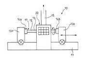
以下、本発明に係るガラス母材の製造方法の実施形態の例について図面を参照して説明する。なお、ここでは、光ファイバのコアとなる部分を有するガラス棒の表面にガラス粉末を堆積させて光ファイバ用のガラス母材を製造する場合について説明する。図1は本発明のガラス母材の製造方法を実施可能な装置の全体構成を示す概略図であり、図2は図1に示した装置の要部構成図であり、図3(A)はプラズマトーチ付近の構成を示す断面図であり、図3(B)はプラズマトーチの平面図である。 Hereinafter, an example of an embodiment of a manufacturing method of a glass base material concerning the present invention is explained with reference to drawings. Here, a case will be described in which a glass base material for an optical fiber is manufactured by depositing glass powder on the surface of a glass rod having a portion serving as a core of the optical fiber. FIG. 1 is a schematic diagram showing the overall configuration of an apparatus capable of carrying out the method for producing a glass base material of the present invention, FIG. 2 is a configuration diagram of the main part of the apparatus shown in FIG. 1, and FIG. It is sectional drawing which shows the structure of a plasma torch vicinity, FIG.3 (B) is a top view of a plasma torch.
図1に示すように、ガラス母材製造装置10では、ベース11の上に、ターゲットであるコアロッドとなるガラス棒12を把持して軸方向(図1において左右方向)に同期して移動可能な一対の把持手段13a、13bが設けられている。また、ベース11の中央部には反応容器20が設けられており、ガラス棒12は反応容器20を貫通して移動可能となっている。なお、反応容器20には、反応容器20の内部の排気を行うための排気装置15が設けられている。
従って、ガラス棒12をチャック14a、14bによって把持して把持手段13a、13bに固定し、チャック14a、14bを回転させながら把持手段13a、13bを同期して往復移動させる。これにより、図1中において矢印で示すようにガラス棒12を回転しながら往復移動させて、反応容器20内においてガラス棒12の表面にクラッドガラス層16を形成し、ガラス母材17を形成する。As shown in FIG. 1, in the glass base
Therefore, the
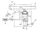
図2に示すように、反応容器20の内部には、プラズマトーチ21およびプラズマトーチ21の外側に螺旋状に巻回された誘導コイル22が設けられている。プラズマトーチ21は支持台23に取り付けられており、プラズマトーチ21の下面には原料、プラズマ発生用ガス、冷却ガス等のガス類24aを供給する入り口21aが設けられている。支持台23はトーチ位置調整機構25の上に設けられており、トーチ位置調整機構25を操作する操作部としての位置調整ハンドル26が反応容器20の外側に設けられている。これは、プラズマの発生が、腐食性ガスを発生する反応容器20内で行われるため、外部から操作できるようにしたものである。従って、作業者は、位置調整ハンドル26を回すことにより、或いは自動で、支持台23およびプラズマトーチ21を、X軸、Y軸、Z軸方向に移動させることができるようになっている。 As shown in FIG. 2, a
また、プラズマトーチ21には、その外周に、誘導コイル22が配設されている。この誘導コイル22は、給電線28を介して発振器27に接続されており、この発振器27から誘導コイル22へ高周波交流電流が供給される。そして、この誘導コイル22に発振器27から高周波交流電流が供給されると、誘導コイル22の内側に高周波電磁界が発生し、この高周波電磁界によってプラズマ生成用ガスが誘導的にイオン化され、プラズマ炎24が発生する。なお、誘導コイル21は銅製巻管で構成されており、内部には冷却水を流すことができるようになっている。 In addition, an
図3に示すように、プラズマトーチ21は、石英から形成された多重管構造とされており、内部には、入り口21aから多重管30が上下方向に挿入されている。多重管30の中心部31には、四塩化ケイ素(SiCl4)を含むガラス原料ガスが供給され、外周部32にはプラズマを発生するためのプラズマ生成用ガスとしてのアルゴンガス(Ar)と反応用の酸素ガス(O2)が供給されている。また、プラズマトーチ21の下端部には、プラズマトーチ21の外周面の接線方向に一対の管21bが設けられており、多重管30の外周面とプラズマトーチ21の内周面との間の最外層33に、冷却用のO2ガスを供給している。従って、O2ガスは、図3(B)に示すように、螺旋状に回転しながら上昇することになる。As shown in FIG. 3, the
また、反応容器20は、プラズマトーチ21の上方に、ガラス母材の製造を行う反応室41を備えている。この反応室41は、ガラス棒12を水平方向に挿通させた状態で内部に収容する。そして、反応室41の底部には開口部43が形成されており、この開口部43には、プラズマトーチ21の先端近傍部分が配置されている。これにより、プラズマトーチ21にて発生したプラズマ炎24が、反応室41内に配置されたガラス棒12に向けられる。また、反応室41には、その上部に、前述した排気装置15が接続されており、反応室41内の排気ガスが排気装置15により排気される。 In addition, the
上記構造のガラス母材製造装置10は、プラズマトーチ21と誘導コイル22との間に、ガス遮蔽部材44が設けられている。このガス遮蔽部材44は、筒状に形成された遮蔽板45を有し、この遮蔽板45には、その上端部に、径方向へ広がる円環状の鍔部46が形成されている。この鍔部46は、その外径が反応室41の隔壁41aの開口部43よりも大径に形成され、反応室41の内部に配置されている。これにより、この鍔部46の外縁部と反応室41の開口部43の開口縁部とが重なり合わされている。そして、開口部43のうちプラズマトーチ21の外側に位置する開口外周部を覆っている。 In the glass base
次に、ガラス母材製造装置10によってガラス棒12の表面にガラス粉末を堆積させ、ガラス棒12からなるコア部と堆積させたガラス粉末により形成されるガラス層からなるクラッド部とを有する光ファイバ用ガラス母材を製造する場合について説明する。
まず、コア部となるガラス棒12を、反応容器20の反応室41へ挿通し、その端部を、把持手段13a、13bのチャック14a、14bにそれぞれ把持させて、水平に支持させる。そして、チャック14a、14bを回転させることにより、ガラス棒12を、その中心軸を中心として回転させる。Next, glass fiber is deposited on the surface of the
First, the
次いで、プラズマトーチ21へガラス原料ガス、プラズマ生成用ガス及び冷却ガスを供給するとともに発振器27から誘導コイル22へ高周波交流電流を供給する。これにより、プラズマ生成用ガスが高周波電磁界によって誘導的にイオン化されてプラズマ炎24が発生し、この高温のプラズマ炎24によってガラス原料ガス中の四塩化ケイ素がガラス粉末となる。ガラス粉末はガラス棒12の表面に堆積し、堆積したガラス粉末がプラズマ炎24の熱によって透明ガラス化して、クラッド部となるクラッドガラス層16が形成されていく。そして、把持手段13a、13bを同期して往復移動させ、ガラス棒12をプラズマ炎24に対して何度も往復移動させることで、ガラス棒12に形成されたクラッドガラス層16の上に、新たなクラッドガラス層16が形成されていく。 Next, a glass raw material gas, a plasma generating gas, and a cooling gas are supplied to the
その際、高周波電磁界により電離してプラズマトーチ21から吹き出されたガスは、ガラス棒12によって跳ね返るなどして誘導コイル22側へ移動しようとする(図3中符号Aで示す)。しかし、この電離したガスは、ガス遮蔽部材44の鍔部46にぶつかり、電離ガスの誘導コイル22への接触が防止される。また、ガス遮蔽部材44とプラズマトーチ21との隙間に移動してきた電離ガスは、遮蔽板45によって、コイル22への移動が遮蔽される。
このように、本実施形態に係るガラス母材の製造方法によれば、ガス遮蔽部材44によって電離ガスの誘導コイル22への接触を確実に防止することができるので、誘導コイル22への電離ガスの接触によるスパークの発生を確実に阻止することができ、誘導コイル22に流す電流の出力を上げてプラズマ炎24を強くしても、ガラス棒12へのガラスの形成を安定して行うことができる。At this time, the gas ionized by the high frequency electromagnetic field and blown out from the
Thus, according to the manufacturing method of the glass base material which concerns on this embodiment, since the contact to the
また、プラズマ炎24を用いる場合、誘導コイル22の内側には高温領域が発生しているが、この高温領域は表皮効果の影響によりプラズマトーチ21の中心軸からずれている。また、プラズマトーチ21の最外層33には冷却ガスが流れており、ここでは急激な温度低下が生じている。
プラズマ炎24はこのような温度分布および温度勾配をもっているので、温度の位置への依存度が大きい。このため、ガラス粉末の堆積を開始する前に、炎の様子を見て、トーチ位置調整機構25によりプラズマトーチ21をX軸、Y軸、Z軸方向へ移動させて最適な位置に調整すると良い。また、発振器27の出力、プラズマ生成用ガス及びガラス原料ガスの供給量なども適宜調節して、プラズマ炎24の強さを適切に調整すると良い。When the
Since the
プラズマトーチ21をZ軸方向(プラズマトーチ21の中心軸方向)へ移動させる場合には、反応室41の隔壁41aに対してガス遮蔽部材44を移動させることなく、ガス遮蔽部材44に対してプラズマトーチ21のみが移動する。そのため、ガス遮蔽部材44によって常時隔壁41aとプラズマトーチ21との隙間を塞いだ状態で、プラズマトーチ21の位置調節が可能である。
また、プラズマトーチ21をX軸、Y軸方向(プラズマトーチ21の中心軸と直交する方向)へ移動させる場合には、反応室41の隔壁41aに対してガス遮蔽部材44を移動させるが、ガス遮蔽部材44に設けられている鍔部46が隔壁41aの開口部43を塞いだ状態を保つことができる。When the
When the
このように、反応容器20に設けられた反応室41の隔壁41aとプラズマトーチ21とを一体化させることなく、誘導コイル22に対して電離ガスを遮蔽することができるので、反応室41に対するプラズマトーチ21の位置を上下方向及び水平方向に調整することができ、ガラス棒12に対してプラズマ炎24を適切に当てて良好な加工を施すことができる。 In this manner, since the ionized gas can be shielded from the
ここで、ガス遮蔽部材44を備えていない従来構造の装置を用いた場合では、ガラスの堆積速度が0.2g/分程度を越えるプラズマパワーで加工を行うと、プラズマ生成後30分程度でスパークが発生したのに対し、ガス遮蔽部材44を備えた上記実施形態のガラス母材製造装置10を用いた場合では、スパークの発生なく安定したプラズマ炎が生成された。これにより、上記実施形態では、誘導コイル31へ供給する高周波交流電流値を高くし、ガラスの堆積速度を0.3g/分程度まで上げることができた。 Here, in the case of using an apparatus having a conventional structure that does not include the gas shielding member 44, if processing is performed with a plasma power at which the glass deposition rate exceeds about 0.2 g / min, a spark is generated in about 30 minutes after the plasma generation. In contrast, when the glass base
なお、上記実施形態では、遮蔽板45の端部に鍔部46を設けたが、鍔部46を設けずに、筒状の遮蔽板45を反応室41の開口部43に密着させて電離ガスを遮蔽しても良い。 In the above embodiment, the
また、他の実施形態として、誘導コイル22側から開口部43側へ向かって電離が生じにくい遮蔽ガスを流す遮蔽ガス供給手段47を使用しても良い。遮蔽ガスとしては、電離が生じにくい、例えば、空気(好ましくはクリーンエアあるいは窒素)が用いられる。遮蔽ガス供給手段47から供給された遮蔽ガスが、誘導コイル22の周囲を通り開口部43へ流れることにより、ガス遮蔽部材44と隔壁41aの僅かな隙間、またはガス遮蔽部材44とプラズマトーチ21の僅かな隙間から電離ガスが漏れてきた場合であっても、誘導コイル22への電離ガスの接触が防がれる。したがって、誘導コイル22への電離ガスの接触によるスパークの発生をより確実に阻止することができる。 Further, as another embodiment, a shielding gas supply means 47 that flows a shielding gas that hardly causes ionization from the
また、他の実施形態として、誘導コイル22の表面が絶縁材によって覆われていてもよい。この絶縁材としては、耐熱性を有するものが良く、例えば、フッ化物樹脂からなる熱収縮性チューブが用いられる。また、絶縁材として、エナメルワニス、ポリイミドフィルム等も使用可能である。これにより、もし誘導コイル22の付近へ電離ガスが漏れてきた場合であっても、誘導コイル22への電離ガスの接触が防がれる。したがって、誘導コイル22への電離ガスの接触によるスパークの発生をより確実に阻止することができる。 As another embodiment, the surface of the
10 ガラス母材製造装置
12 ガラス棒(ガラス体)
20 反応容器
21 プラズマトーチ
22 誘導コイル(コイル)
41 反応室
41a 隔壁
43 開口部
44 ガス遮蔽部材
45 遮蔽板
46 鍔部10 Glass base
20
41
Claims (4)
Translated fromJapanese前記トーチと前記コイルの隙間にガス遮蔽部材を設けた状態で、前記コイルの巻き部中心付近に生成されるプラズマ炎を使って形成したガラス粉末を反応容器内に放出し、前記反応容器内に配置したガラス体に堆積させ、ガラス母材を製造するガラス母材の製造方法。Using a torch for flowing a glass generating material gas and a plasma generating gas, and a coil surrounding a part of the torch and ionizing the plasma generating gas,
In a state where a gas shielding member is provided in the gap between the torch and the coil, glass powder formed using a plasma flame generated near the center of the winding portion of the coil is discharged into the reaction vessel, A method for producing a glass base material, wherein the glass base material is produced by depositing on a placed glass body.
Priority Applications (1)
| Application Number | Priority Date | Filing Date | Title |
|---|---|---|---|
| JP2005155039AJP4581844B2 (en) | 2005-05-27 | 2005-05-27 | Manufacturing method of glass base material |
Applications Claiming Priority (1)
| Application Number | Priority Date | Filing Date | Title |
|---|---|---|---|
| JP2005155039AJP4581844B2 (en) | 2005-05-27 | 2005-05-27 | Manufacturing method of glass base material |
Publications (2)
| Publication Number | Publication Date |
|---|---|
| JP2006327887Atrue JP2006327887A (en) | 2006-12-07 |
| JP4581844B2 JP4581844B2 (en) | 2010-11-17 |
Family
ID=37549969
Family Applications (1)
| Application Number | Title | Priority Date | Filing Date |
|---|---|---|---|
| JP2005155039AExpired - Fee RelatedJP4581844B2 (en) | 2005-05-27 | 2005-05-27 | Manufacturing method of glass base material |
Country Status (1)
| Country | Link |
|---|---|
| JP (1) | JP4581844B2 (en) |
Citations (3)
| Publication number | Priority date | Publication date | Assignee | Title |
|---|---|---|---|---|
| JP2001011638A (en)* | 1999-06-23 | 2001-01-16 | Jeol Ltd | High frequency induction thermal plasma equipment |
| JP2001217097A (en)* | 2000-02-02 | 2001-08-10 | Toshiba Corp | High-frequency plasma device |
| JP2003149794A (en)* | 2001-08-01 | 2003-05-21 | Corning Inc | Method for making photomask material by plasma induction |
- 2005
- 2005-05-27JPJP2005155039Apatent/JP4581844B2/ennot_activeExpired - Fee Related
Patent Citations (3)
| Publication number | Priority date | Publication date | Assignee | Title |
|---|---|---|---|---|
| JP2001011638A (en)* | 1999-06-23 | 2001-01-16 | Jeol Ltd | High frequency induction thermal plasma equipment |
| JP2001217097A (en)* | 2000-02-02 | 2001-08-10 | Toshiba Corp | High-frequency plasma device |
| JP2003149794A (en)* | 2001-08-01 | 2003-05-21 | Corning Inc | Method for making photomask material by plasma induction |
Also Published As
| Publication number | Publication date |
|---|---|
| JP4581844B2 (en) | 2010-11-17 |
Similar Documents
| Publication | Publication Date | Title |
|---|---|---|
| JP4889834B2 (en) | Plasma processing apparatus and method | |
| US20080035612A1 (en) | Systems and Methods Utilizing an Aperture with a Reactive Atom Plasma Torch | |
| US8192807B2 (en) | Ring plasma jet method and apparatus for making an optical fiber preform | |
| JP2015500557A (en) | Gas injector for plasma applicator | |
| US6770165B2 (en) | Apparatus for plasma treatment | |
| JP2004203682A (en) | Method and apparatus for manufacturing optical fiber preform | |
| CN103151234A (en) | Plasma treatment apparatus and plasma treatment method | |
| US12325657B2 (en) | Wire-drawing optical fiber base material manufacturing method and manufacturing apparatus | |
| JPH0647477B2 (en) | Method for producing solid glass preforms from hollow preforms | |
| CN100536634C (en) | Plasma processing device and method | |
| JP3812861B2 (en) | Plasma-based equipment for etching or deposition | |
| JP4581844B2 (en) | Manufacturing method of glass base material | |
| JP5014324B2 (en) | High-frequency thermal plasma torch for solid synthesis | |
| JPH0855699A (en) | Plasma processing device | |
| JP2007501182A (en) | Ring plasma jet optical fiber preform manufacturing method and apparatus | |
| US20060196230A1 (en) | Plasma apparatus and apparatus for fabricating optical fiber preform by using the same | |
| JP2006302652A (en) | Plasma processing equipment | |
| KR100702738B1 (en) | Furnace for fiber cutting and fiber cutting method | |
| JP5111348B2 (en) | High frequency induction thermal plasma equipment | |
| JP2008251857A (en) | Plasma processing equipment | |
| JP2592025B2 (en) | Induction plasma torch for decompression | |
| JP2020205172A (en) | Cooling jacket and plasma generator | |
| JP2007035486A (en) | Method for controlling driving current of plasma generator and plasma generator | |
| JP2001011638A (en) | High frequency induction thermal plasma equipment | |
| KR100507627B1 (en) | Furnace for manufacturing optical fibers, having different diameters at inlet and outlet |
Legal Events
| Date | Code | Title | Description |
|---|---|---|---|
| A621 | Written request for application examination | Effective date:20080424 Free format text:JAPANESE INTERMEDIATE CODE: A621 | |
| A977 | Report on retrieval | Free format text:JAPANESE INTERMEDIATE CODE: A971007 Effective date:20100210 | |
| A131 | Notification of reasons for refusal | Free format text:JAPANESE INTERMEDIATE CODE: A131 Effective date:20100216 | |
| A521 | Written amendment | Free format text:JAPANESE INTERMEDIATE CODE: A523 Effective date:20100415 | |
| TRDD | Decision of grant or rejection written | ||
| A01 | Written decision to grant a patent or to grant a registration (utility model) | Effective date:20100803 Free format text:JAPANESE INTERMEDIATE CODE: A01 | |
| A01 | Written decision to grant a patent or to grant a registration (utility model) | Free format text:JAPANESE INTERMEDIATE CODE: A01 | |
| A61 | First payment of annual fees (during grant procedure) | Free format text:JAPANESE INTERMEDIATE CODE: A61 Effective date:20100816 | |
| R150 | Certificate of patent (=grant) or registration of utility model | Free format text:JAPANESE INTERMEDIATE CODE: R150 | |
| FPAY | Renewal fee payment (prs date is renewal date of database) | Free format text:PAYMENT UNTIL: 20130910 Year of fee payment:3 | |
| LAPS | Cancellation because of no payment of annual fees |