JP2006325054A - TCP / IP reception processing circuit and semiconductor integrated circuit having the same - Google Patents
TCP / IP reception processing circuit and semiconductor integrated circuit having the sameDownload PDFInfo
- Publication number
- JP2006325054A JP2006325054AJP2005147618AJP2005147618AJP2006325054AJP 2006325054 AJP2006325054 AJP 2006325054AJP 2005147618 AJP2005147618 AJP 2005147618AJP 2005147618 AJP2005147618 AJP 2005147618AJP 2006325054 AJP2006325054 AJP 2006325054A
- Authority
- JP
- Japan
- Prior art keywords
- packet
- storage area
- stored
- lower layer
- tcp
- Prior art date
- Legal status (The legal status is an assumption and is not a legal conclusion. Google has not performed a legal analysis and makes no representation as to the accuracy of the status listed.)
- Withdrawn
Links
Images


Classifications
- H—ELECTRICITY
- H04—ELECTRIC COMMUNICATION TECHNIQUE
- H04L—TRANSMISSION OF DIGITAL INFORMATION, e.g. TELEGRAPHIC COMMUNICATION
- H04L69/00—Network arrangements, protocols or services independent of the application payload and not provided for in the other groups of this subclass
- H04L69/16—Implementation or adaptation of Internet protocol [IP], of transmission control protocol [TCP] or of user datagram protocol [UDP]
- H—ELECTRICITY
- H04—ELECTRIC COMMUNICATION TECHNIQUE
- H04L—TRANSMISSION OF DIGITAL INFORMATION, e.g. TELEGRAPHIC COMMUNICATION
- H04L69/00—Network arrangements, protocols or services independent of the application payload and not provided for in the other groups of this subclass
- H04L69/12—Protocol engines
- H—ELECTRICITY
- H04—ELECTRIC COMMUNICATION TECHNIQUE
- H04L—TRANSMISSION OF DIGITAL INFORMATION, e.g. TELEGRAPHIC COMMUNICATION
- H04L69/00—Network arrangements, protocols or services independent of the application payload and not provided for in the other groups of this subclass
- H04L69/16—Implementation or adaptation of Internet protocol [IP], of transmission control protocol [TCP] or of user datagram protocol [UDP]
- H04L69/161—Implementation details of TCP/IP or UDP/IP stack architecture; Specification of modified or new header fields
- H—ELECTRICITY
- H04—ELECTRIC COMMUNICATION TECHNIQUE
- H04L—TRANSMISSION OF DIGITAL INFORMATION, e.g. TELEGRAPHIC COMMUNICATION
- H04L69/00—Network arrangements, protocols or services independent of the application payload and not provided for in the other groups of this subclass
- H04L69/30—Definitions, standards or architectural aspects of layered protocol stacks
- H04L69/32—Architecture of open systems interconnection [OSI] 7-layer type protocol stacks, e.g. the interfaces between the data link level and the physical level
- H04L69/322—Intralayer communication protocols among peer entities or protocol data unit [PDU] definitions
- H04L69/326—Intralayer communication protocols among peer entities or protocol data unit [PDU] definitions in the transport layer [OSI layer 4]
- H—ELECTRICITY
- H04—ELECTRIC COMMUNICATION TECHNIQUE
- H04L—TRANSMISSION OF DIGITAL INFORMATION, e.g. TELEGRAPHIC COMMUNICATION
- H04L69/00—Network arrangements, protocols or services independent of the application payload and not provided for in the other groups of this subclass
- H04L69/30—Definitions, standards or architectural aspects of layered protocol stacks
- H04L69/32—Architecture of open systems interconnection [OSI] 7-layer type protocol stacks, e.g. the interfaces between the data link level and the physical level
Landscapes
- Engineering & Computer Science (AREA)
- Computer Security & Cryptography (AREA)
- Computer Networks & Wireless Communication (AREA)
- Signal Processing (AREA)
- Communication Control (AREA)
Abstract
Translated fromJapaneseDescription
Translated fromJapanese本発明は、TCP/IP(Transmission Control Protocol/Internet Protocol)の受信処理を行うためのTCP/IP受信処理回路に関する。さらに、本発明は、そのようなTCP/IP受信処理回路を具備する半導体集積回路に関する。 The present invention relates to a TCP / IP reception processing circuit for performing TCP / IP (Transmission Control Protocol / Internet Protocol) reception processing. Furthermore, the present invention relates to a semiconductor integrated circuit including such a TCP / IP reception processing circuit.
現在、インターネット、LAN(Local Area Network)等において、TCP/IPと呼ばれる通信プロトコルの階層モデルが広く用いられている。図8は、TCP/IP階層モデルの各レイヤとISO(International Organization for Standardization)で制定されたOSI(Open Systems Interconnection)参照モデルの各レイヤとのおおよその対応関係を示す図である。 Currently, a hierarchical model of a communication protocol called TCP / IP is widely used in the Internet, LAN (Local Area Network) and the like. FIG. 8 is a diagram showing an approximate correspondence between each layer of the TCP / IP hierarchical model and each layer of the OSI (Open Systems Interconnection) reference model established by ISO (International Organization for Standardization).
TCP/IP階層モデルのネットワークインタフェース層としてはEthernet(登録商標)が、TCP/IP階層モデルのインターネット層としてはIP(Internet Protocol)バージョン4(以下、単に「IP」という)が、TCP/IP階層モデルのトランスポート層としてはTCP(Transmission Control Protocol)又はUDP(User Datagram Protocol)が、広く用いられている。なお、Ethernet(登録商標)は、IEEE802.3等に、IPは、RFC(Request For Comments)791等に、TCPは、RFC793等に、UDPは、RFC768等に、それぞれ規定されている。 The network interface layer of the TCP / IP hierarchical model is Ethernet (registered trademark), and the Internet layer of the TCP / IP hierarchical model is IP (Internet Protocol) version 4 (hereinafter simply referred to as “IP”). As a transport layer of the model, TCP (Transmission Control Protocol) or UDP (User Datagram Protocol) is widely used. Note that Ethernet (registered trademark) is specified in IEEE 802.3, etc., IP is specified in RFC (Request For Comments) 791, etc., TCP is specified in RFC 793, etc., and UDP is specified in RFC 768, etc.
また、ネットワーク管理用のプロトコルとして、TCP/IP階層モデルのインターネット層に相当するARP(Address Resolution Protocol)及びRARP(Reverse Address Resolution Protocol)、TCP/IP階層モデルのトランスポート層に相当するICMP(Internet Control Message Protocol)が、広く用いられている。なお、ARPは、RFC826等に、RARPは、RFC903等に、ICMPは、RFC792等に、それぞれ規定されている。 As protocols for network management, ARP (Address Resolution Protocol) and RARP (Reverse Address Resolution Protocol) corresponding to the Internet layer of the TCP / IP hierarchical model, ICMP (Internet) corresponding to the transport layer of the TCP / IP hierarchical model Control Message Protocol) is widely used. ARP is defined in RFC826 and the like, RARP is defined in RFC903 and the like, and ICMP is defined in RFC792 and the like.
図9は、Ethernet(登録商標)フレーム(以下、単に「フレーム」という)のフォーマットを示す図である。図9に示すように、フレームは、ヘッダと、ペイロードとを有する。なお、フレームが実際にネットワーク上に送信される際には、先頭にプリアンブルが、末尾にCRC(Cyclic Redundancy Check)を格納したフレームチェックシーケンス(Frame Check Sequence)が、それぞれ付加される。 FIG. 9 is a diagram showing a format of an Ethernet (registered trademark) frame (hereinafter simply referred to as “frame”). As shown in FIG. 9, the frame has a header and a payload. When a frame is actually transmitted on the network, a frame check sequence (Frame Check Sequence) in which a preamble is stored at the beginning and a CRC (Cyclic Redundancy Check) is added at the end is added.
図10は、IPパケットのフォーマットを示す図である。図10に示すように、IPパケットは、IPヘッダと、IPペイロードとを有する。IPパケットは、フレームのペイロード内(図9参照)に格納される。 FIG. 10 is a diagram showing the format of an IP packet. As shown in FIG. 10, the IP packet has an IP header and an IP payload. The IP packet is stored in the payload of the frame (see FIG. 9).
図11は、ARP、RARPパケットのフォーマットを示す図である。ARP、RARPパケットは、フレームのペイロード内(図9参照)に格納される。 FIG. 11 is a diagram showing the format of ARP and RARP packets. The ARP and RARP packets are stored in the payload of the frame (see FIG. 9).
図12は、TCPパケットのフォーマットを示す図である。図12に示すように、TCPパケットは、TCPヘッダと、TCPペイロードとを有する。TCPパケットは、IPパケットのペイロード内(図10参照)に格納される。 FIG. 12 is a diagram illustrating a format of a TCP packet. As shown in FIG. 12, the TCP packet has a TCP header and a TCP payload. The TCP packet is stored in the payload of the IP packet (see FIG. 10).
図13は、UDPパケットのフォーマットを示す図である。図13に示すように、UDPパケットは、UDPヘッダと、UDPペイロードとを有する。UDPパケットは、IPパケットのペイロード内(図10参照)に格納される。 FIG. 13 is a diagram illustrating a format of a UDP packet. As shown in FIG. 13, the UDP packet has a UDP header and a UDP payload. The UDP packet is stored in the payload of the IP packet (see FIG. 10).
図14は、ICMPパケットのフォーマットを示す図である。ICMPパケットは、IPパケットのペイロード内(図10参照)に格納される。 FIG. 14 is a diagram showing a format of an ICMP packet. The ICMP packet is stored in the payload of the IP packet (see FIG. 10).
従来のTCP/IPの受信処理においては、ネットワークインタフェース層をハードウェア回路(以下、NIC(Network Interface Card)という)で実現し、インターネット層〜アプリケーション層をCPUとソフトウェア(プログラム)で実現する場合が多かった。しかしながら、インターネット層〜アプリケーション層をCPUとソフトウェア(プログラム)で実現する場合、CPUの負荷が大きいという問題があった。そこで、近年においては、インターネット層及び/又はトランスポート層の一部をハードウェア回路で実現することにより、CPUの負荷を軽減することが行われるようになってきている。 In conventional TCP / IP reception processing, the network interface layer may be realized by a hardware circuit (hereinafter referred to as NIC (Network Interface Card)), and the Internet layer to application layer may be realized by a CPU and software (program). There were many. However, when the Internet layer to the application layer are realized by a CPU and software (program), there is a problem that the load on the CPU is large. Therefore, in recent years, the load on the CPU has been reduced by realizing a part of the Internet layer and / or the transport layer with a hardware circuit.
関連する技術として、下記の特許文献1には、ネットワークアダプタと複数の層を有するプロトコルスタックとを備えたネットワークノードにおいてデータを受信する方法であって、ネットワーク媒体からの着信データパケットを形成するパケットバイトをメモリに転送し、パケットバイトがネットワーク媒体からメモリへ転送される際に着信データパケットの一部を形成するパケットバイトからコードを計算し、該コードをプロトコルスタックに関連するコードチャネルへ転送し、プロトコルスタックの複数の層のうちの第1の層におけるデータパケットから抽出されたデータを受信し、該抽出されたデータをコードチャネルからのコードを使用して検証する、という各ステップを有することを特徴とする方法が掲載されている。
この方法は、パケットがネットワーク媒体からメモリへ転送される際にTCPのチェックサム等を計算することができるものである。As a related technique, the following
This method is capable of calculating a TCP checksum or the like when a packet is transferred from a network medium to a memory.
また、下記の特許文献2には、ネットワークに接続され、主記憶装置とネットワークアダプタを有する計算機システムにおいて、ネットワークアダプタによってネットワークから受信されたネットワークパケットを主記憶装置に送る方法であって、(a)ネットワークアダプタによりネットワークパケットのヘッダを主記憶装置中の第1のメモリバッファに置くステップ;(b)ネットワークアダプタによりネットワークパケットに含まれるデータを主記憶装置中の第2のメモリバッファの最初に置くステップを備える方法が掲載されている。
この方法は、着信パケットのヘッダとデータを分離して別々のメモリバッファに入れることができるものである。
In this method, the header and data of the incoming packet can be separated and put into separate memory buffers.
ところで、一般に、アプリケーション層において実行されるアプリケーションプログラム(ウェブブラウザプログラム、メールクライアントプログラム等)は、通信端点(OS(Operating System)上においてAPI(Application Programming Interface)によって提供される)からパケットを受け取る。この通信端点には、OSによってパケットが供給される。OSは、NICからデバイスドライバ(プログラム)経由でパケットを受け取ると、現に存在している通信端点宛てのパケットであるか否かを判定し、現に存在している通信端点宛てのパケットである場合に、パケットを該当する通信端点に供給する。 By the way, generally, an application program (web browser program, mail client program, etc.) executed in the application layer receives a packet from a communication endpoint (provided by an API (Application Programming Interface) on an OS (Operating System)). A packet is supplied to the communication end point by the OS. When the OS receives a packet from the NIC via a device driver (program), the OS determines whether the packet is addressed to a communication endpoint that currently exists, and if the packet is addressed to a communication endpoint that currently exists. The packet is supplied to the corresponding communication end point.
なお、下記の非特許文献1には、ITRONにおけるTCP/IPの通信端点のAPIの仕様が掲載されている。 The following Non-Patent
一般に、ネットワークインタフェース層〜トランスポート層においては、パケットを処理の基本単位としており、通信端点のAPIも、パケットを1つずつアプリケーション層に渡すようにコーディングされている場合が多い。このような場合、アプリケーション層は、通信端点からパケットを1つずつ受け取ることとなる。 In general, in the network interface layer to the transport layer, a packet is a basic unit of processing, and the API at the communication end point is often coded so as to pass the packet to the application layer one by one. In such a case, the application layer receives packets one by one from the communication end point.
しかしながら、アプリケーションプログラムの内部においては、複数のパケットを含む論理的データストリームを処理の基本単位としていることが多い。そのため、アプリケーション層において複数のパケットから論理的データストリームを作成する必要があるが、この作成の負荷は、システム全体で見るとかなり大きなものとなる。 However, in an application program, a logical data stream including a plurality of packets is often used as a basic unit of processing. Therefore, it is necessary to create a logical data stream from a plurality of packets in the application layer. However, the load of this creation is considerably large when viewed from the entire system.
また、NICにおいては、TCP又はUDPのヘッダ部とTCP又はUDPのデータ部の分割や、チェックサム検証等が行われている。しかしながら、NICによるヘッダ部とデータ部の分割やチェックサム検証等で得られた解析情報が、OSによる現に存在している通信端点宛てのパケットであるか否かの判定において適切に利用されていなかった。
さらに、NIC〜OS又はAPI〜アプリケーションプログラム(ネットワークインタフェース層〜アプリケーション層)の経路において、フレーム又はパケットのメモリコピーが発生してしまっていた。In the NIC, a TCP or UDP header part and a TCP or UDP data part are divided, checksum verification, and the like are performed. However, the analysis information obtained by dividing the header part and the data part by NIC or by checksum verification is not appropriately used in determining whether or not the packet is addressed to the communication endpoint currently existing by the OS. It was.
Further, a memory copy of a frame or packet has occurred in the path from NIC to OS or API to application program (network interface layer to application layer).
そこで、上記の点に鑑み、本発明は、複数のパケットから論理的データストリームを作成する負荷を軽減すること等が可能なTCP/IP受信処理回路を提供することを目的とする。また、本発明はそのようなTCP/IP受信処理回路を具備する半導体集積回路を提供することを更なる目的とする。 Therefore, in view of the above points, an object of the present invention is to provide a TCP / IP reception processing circuit capable of reducing the load of creating a logical data stream from a plurality of packets. Another object of the present invention is to provide a semiconductor integrated circuit including such a TCP / IP reception processing circuit.
以上の課題を解決するため、本発明に係るTCP/IP受信処理回路は、下位レイヤから受け取ったフレームに格納されているパケットを上位レイヤがアクセス可能なメモリに転送するTCP/IP(Transmission Control Protocol/Internet Protocol)受信処理回路であって、メモリが、所定の通信端点宛ての複数のパケットをそれぞれ格納するための複数のパケット格納領域と、各々が有する第1のポインタによってリンクされている複数のディスクリプタテーブルであって、パケット格納領域を指し示すための第2のポインタ及び第2のポインタによって指し示されるパケット格納領域にパケットを書き込むことが可能であるか否かを示すパケット書込み可否情報をそれぞれ有する複数のディスクリプタテーブルと、を含む通信端点情報領域を有しており、下位レイヤから受け取ったフレームに格納されているパケットが所定の通信端点宛てのパケットである場合に、第1のポインタ及びパケット書込み可否情報を利用して複数のディスクリプタテーブルの中からパケットを書き込むことが可能なパケット格納領域を指し示す1つのディスクリプタテーブルを決定し、下位レイヤから受け取ったフレームに格納されているパケットを当該ディスクリプタテーブル内の第2のポインタによって指し示されるパケット格納領域内に転送する。 In order to solve the above problems, a TCP / IP reception processing circuit according to the present invention transfers a packet stored in a frame received from a lower layer to a memory accessible by the upper layer to a TCP / IP (Transmission Control Protocol). / Internet Protocol) receiving processing circuit, wherein the memory is linked to a plurality of packet storage areas for storing a plurality of packets addressed to a predetermined communication end point, and a plurality of first pointers included in each of the plurality of packet storage areas Each of the descriptor tables has a second pointer for indicating the packet storage area and packet write enable / disable information indicating whether the packet can be written to the packet storage area indicated by the second pointer. A communication endpoint information area including a plurality of descriptor tables; Thus, when the packet stored in the frame received from the lower layer is a packet addressed to a predetermined communication endpoint, the packet is written from the plurality of descriptor tables using the first pointer and the packet writability information. One descriptor table indicating a packet storage area that can be transmitted is determined, and the packet stored in the frame received from the lower layer is transferred to the packet storage area indicated by the second pointer in the descriptor table. .
このTCP/IP受信処理回路において、複数のパケット格納領域の各々が、パケットのヘッダを格納するためのヘッダ格納領域と、パケットのペイロードを格納するためのペイロード格納領域と、を含んでおり、第2のポインタが、ヘッダ格納領域を指し示す第3のポインタと、ペイロード格納領域を指し示す第4のポインタと、を含んでおり、下位レイヤから受け取ったフレームに格納されているパケットが所定の通信端点宛てのパケットである場合に、第1のポインタ及びパケット書き込み可否情報を利用して複数のディスクリプタテーブルの中からパケットを書き込むことが可能なパケット格納領域を指し示す1つのディスクリプタテーブルを決定し、下位レイヤから受け取ったフレームに格納されているパケットのヘッダを当該ディスクリプタテーブル内の第3のポインタによって指し示されるヘッダ格納領域内に転送し、下位レイヤから受け取ったフレームに格納されているパケットのペイロードを当該ディスクリプタテーブル内の第4のポインタによって指し示されるペイロード格納領域内に転送するようにしても良い。 In this TCP / IP reception processing circuit, each of the plurality of packet storage areas includes a header storage area for storing a packet header and a payload storage area for storing a packet payload, 2 pointers include a third pointer that points to the header storage area and a fourth pointer that points to the payload storage area, and the packet stored in the frame received from the lower layer is addressed to a predetermined communication endpoint One descriptor table indicating a packet storage area in which a packet can be written is determined from a plurality of descriptor tables using the first pointer and the packet writability information. The header of the packet stored in the received frame is Transfer the payload of the packet stored in the frame received from the lower layer to the header storage area pointed to by the third pointer in the scripter table, and store the payload pointed to by the fourth pointer in the descriptor table You may make it transfer within an area | region.
また、複数のパケット格納領域内のペイロード格納領域が、メモリ内の連続するアドレスに配置されているようにしても良い。 Further, the payload storage areas in the plurality of packet storage areas may be arranged at consecutive addresses in the memory.
また、複数のディスクリプタテーブルの各々が、ヘッダ格納領域に格納可能なヘッダのサイズを表すヘッダ格納領域サイズ情報と、ペイロード格納領域に格納可能なペイロードのサイズを表すペイロード格納領域サイズ情報と、を更に含んでおり、下位レイヤから受け取ったフレームに格納されているパケットが所定の通信端点宛てのパケットである場合に、第1のポインタ及びパケット書き込み可否情報を利用して複数のディスクリプタテーブルの中からパケットを書き込むことが可能なパケット格納領域を指し示す1つのディスクリプタテーブルを決定し、当該ディスクリプタテーブル内のヘッダ格納領域サイズ情報によって表されるサイズより下位レイヤから受け取ったフレームに格納されているパケットのヘッダのサイズが大きいときに、下位レイヤから受け取ったフレームに格納されているパケットのヘッダの内の当該ディスクリプタテーブル内のヘッダ格納領域に格納可能な部分を当該ディスクリプタテーブル内のヘッダ格納領域に転送し、当該ディスクリプタテーブル内のペイロード格納領域サイズ情報によって表されるサイズより下位レイヤから受け取ったフレームに格納されているパケットのペイロードのサイズが大きいときに、下位レイヤから受け取ったフレームに格納されているパケットのペイロードの内の当該ディスクリプタテーブル内のペイロード格納領域に格納可能な部分を当該ディスクリプタテーブル内のペイロード格納領域に転送するようにしても良い。 Each of the plurality of descriptor tables further includes header storage area size information indicating a header size that can be stored in the header storage area, and payload storage area size information indicating a payload size that can be stored in the payload storage area. And the packet stored in the frame received from the lower layer is a packet addressed to a predetermined communication end point, and the packet is stored from the plurality of descriptor tables using the first pointer and the packet writability information. One descriptor table indicating a packet storage area that can be written to is determined, and the header of the packet stored in the frame received from the lower layer than the size represented by the header storage area size information in the descriptor table is determined. If the size is large The portion of the packet header stored in the frame received from the lower layer is transferred to the header storage area in the descriptor table and transferred to the header storage area in the descriptor table. When the size of the payload of the packet stored in the frame received from the lower layer is larger than the size represented by the payload storage area size information, the corresponding one of the payloads of the packets stored in the frame received from the lower layer A portion that can be stored in the payload storage area in the descriptor table may be transferred to the payload storage area in the descriptor table.
また、所定の通信端点の論理的データストリームブロックの初期サイズを上位レイヤによって設定可能な減算カウンタを具備し、下位レイヤから受け取ったフレームに格納されているパケットが所定の通信端点宛てのパケットである場合に、減算カウンタにおいて、下位レイヤから受け取ったフレームに格納されているパケットのペイロードのサイズに相当する値の減算を行い、減算カウンタの値が0になったときに、その旨を通知するための制御信号を上位レイヤに出力するようにしても良い。 In addition, a subtraction counter capable of setting the initial size of the logical data stream block of a predetermined communication end point by an upper layer is provided, and a packet stored in a frame received from the lower layer is a packet addressed to the predetermined communication end point In this case, in the subtraction counter, a value corresponding to the payload size of the packet stored in the frame received from the lower layer is subtracted, and when the value of the subtraction counter becomes 0, the fact is notified The control signal may be output to an upper layer.
また、所定の通信端点がTCP(Transmission Control Protocol)の通信端点である場合に、メモリが、所定の通信端点宛てのRSTパケットを格納するためのRSTパケット格納領域と、RSTパケット格納領域を指し示すためのポインタを有するRSTディスクリプタテーブルと、を更に有し、下位レイヤから受け取ったフレームに格納されているパケットが所定の通信端点宛てのRSTパケットである場合に、RSTディスクリプタテーブル内のポインタによって指し示されるRSTパケット格納領域内にRSTパケットを転送するようにしても良い。 In addition, when the predetermined communication endpoint is a TCP (Transmission Control Protocol) communication endpoint, the memory indicates an RST packet storage area for storing an RST packet addressed to the predetermined communication endpoint and an RST packet storage area. And an RST descriptor table having a pointer, and when a packet stored in a frame received from a lower layer is an RST packet addressed to a predetermined communication end point, is indicated by a pointer in the RST descriptor table The RST packet may be transferred into the RST packet storage area.
また、所定の通信端点のシーケンス番号の初期値を上位レイヤによって設定可能な加算カウンタを具備し、下位レイヤから受け取ったフレームに格納されているパケットが所定の通信端点宛てのパケットである場合に、当該パケットのTCPヘッダ内のシーケンス番号と加算カウンタの値とが一致する場合に、下位レイヤから受け取ったフレームに格納されているパケットをメモリに転送するとともに、加算カウンタの値をインクリメントするようにしても良い。 In addition, an addition counter that can set an initial value of a sequence number of a predetermined communication endpoint by an upper layer is provided, and a packet stored in a frame received from a lower layer is a packet addressed to a predetermined communication endpoint. When the sequence number in the TCP header of the packet matches the value of the addition counter, the packet stored in the frame received from the lower layer is transferred to the memory, and the value of the addition counter is incremented. Also good.
また、複数のディスクリプタテーブルの各々が、下位レイヤから受け取ったフレーム又は下位レイヤから受け取ったフレームに格納されているパケットの解析結果を格納するための解析結果格納領域を更に含んでおり、下位レイヤから受け取ったフレームに格納されているパケットが所定の通信端点宛てのパケットである場合に、第1のポインタ及びパケット書込み可否情報を利用して複数のディスクリプタテーブルの中からパケットを書き込むことが可能なパケット格納領域を指し示す1つのディスクリプタテーブルを決定し、下位レイヤから受け取ったフレームに格納されているパケットを当該ディスクリプタテーブル内の第2のポインタによって指し示されるパケット格納領域内に転送するとともに、下位レイヤから受け取ったフレーム又は下位レイヤから受け取ったフレームに格納されているパケットの解析結果を当該ディスクリプタテーブル内の解析結果格納領域に書き込むようにしても良い。 Each of the plurality of descriptor tables further includes an analysis result storage area for storing an analysis result of a packet received from a frame received from a lower layer or a frame received from a lower layer. A packet capable of writing a packet from a plurality of descriptor tables using the first pointer and the packet writability information when the packet stored in the received frame is a packet addressed to a predetermined communication end point One descriptor table indicating the storage area is determined, and the packet stored in the frame received from the lower layer is transferred to the packet storage area indicated by the second pointer in the descriptor table. The received frame Or an analysis result of the packet stored in the frame received from the lower layer may be written in the analysis result storage area in the descriptor table.
また、メモリが、複数の通信端点にそれぞれ対応する複数の通信端点情報領域を有しており、下位レイヤから受け取ったフレームに格納されているパケットが複数の通信端点のいずれかの通信端点宛てのパケットである場合に、複数の通信端点情報領域の中の当該パケットの宛先である通信端点に対応する通信端点情報領域の中のディスクリプタテーブル内で指し示されるパケット格納領域に当該パケットを書き込むようにしても良い。 In addition, the memory has a plurality of communication endpoint information areas respectively corresponding to the plurality of communication endpoints, and the packet stored in the frame received from the lower layer is addressed to any one of the plurality of communication endpoints. If the packet is a packet, the packet is written to the packet storage area indicated in the descriptor table in the communication endpoint information area corresponding to the communication endpoint that is the destination of the packet in the plurality of communication endpoint information areas. May be.
また、メモリが、下位レイヤから受け取ったフレームに格納されているパケットのプロトコルが所定のプロトコルでない場合における当該フレーム又は下位レイヤから受け取ったフレームに格納されているパケットが複数の通信端点のいずれ宛てでもないパケットである場合における当該パケットを格納するための第2の通信端点情報領域を更に有しており、下位レイヤから受け取ったフレームに格納されているパケットのプロトコルが所定のプロトコルでない場合又は下位レイヤから受け取ったフレームに格納されているパケットが複数の通信端点のいずれ宛てでもないパケットである場合に、下位レイヤから受け取ったフレームに格納されているパケットのプロトコルが所定のプロトコルでない場合における当該フレーム又は下位レイヤから受け取ったフレームに格納されているパケットが複数の通信端点のいずれ宛てでもないパケットである場合における当該パケットを第2の通信端点情報領域の中のディスクリプタテーブル内で指し示されるパケット格納領域に転送するようにしても良い。 In addition, when the protocol of the packet stored in the frame received from the lower layer is not a predetermined protocol, the packet stored in the frame received from the lower layer or the frame is addressed to any of the communication end points. A second communication endpoint information area for storing the packet when the packet is not a packet, and the protocol of the packet stored in the frame received from the lower layer is not a predetermined protocol or the lower layer When the packet stored in the frame received from the packet is not addressed to any of the plurality of communication end points, the frame in the case where the protocol of the packet stored in the frame received from the lower layer is not a predetermined protocol or Lower layer When the packet stored in the received frame is not addressed to any of the plurality of communication endpoints, the packet is transferred to the packet storage area indicated in the descriptor table in the second communication endpoint information area You may make it do.
また、本発明に係る半導体集積回路は、本発明に係るTCP/IP受信処理回路を具備する。 The semiconductor integrated circuit according to the present invention includes the TCP / IP reception processing circuit according to the present invention.
以下、図面を参照しながら、本発明の実施の形態について説明する。なお、同一の構成要素については、同一の参照番号で示している。
図1は、本発明の一実施形態としてのTCP/IP(Transmission Control Protocol/Internet Protocol)受信処理回路を用いたコンピュータの概要を示すブロック図である。このコンピュータ1は、ネットワークNに接続された物理層処理回路(PHY)2と、MAC(Media Access Control)処理回路3と、MACブリッジ回路4と、本発明の一実施形態としてのTCP/IP受信処理回路5と、TCP/IP送信処理回路6と、インタフェース回路7と、CPU8と、メインメモリ9と、HDD(ハードディスクドライブ)10と、入力部11と、表示部12とを具備する。Hereinafter, embodiments of the present invention will be described with reference to the drawings. In addition, about the same component, it has shown with the same reference number.
FIG. 1 is a block diagram showing an outline of a computer using a TCP / IP (Transmission Control Protocol / Internet Protocol) reception processing circuit as an embodiment of the present invention. The
本実施形態においては、TCP/IP階層モデルのネットワークインタフェース層がEthernet(登録商標)であるものとし、物理層処理回路2、MAC処理回路3、及び、MACブリッジ回路4が、ネットワークインタフェース層を担うものとする。物理層処理回路2は、ネットワークNに接続されており、MAC処理回路3は、物理層処理回路2に接続されており、MACブリッジ回路4は、MAC処理回路3に接続されている。 In the present embodiment, the network interface layer of the TCP / IP hierarchical model is assumed to be Ethernet (registered trademark), and the physical
また、TCP/IP受信処理回路5、TCP/IP送信処理回路6、及び、インタフェース回路7が、インターネット層及びトランスポート層の一部を担うものとする。TCP/IP受信処理回路5及びTCP/IP送信処理回路6は、MACブリッジ回路4とインタフェース回路7との間にそれぞれ接続されている。 In addition, the TCP / IP
また、CPU8、メインメモリ9、HDD10、入力部11、及び、表示部12が、TCP/IP階層モデルのインターネット層及びトランスポート層の一部とアプリケーション層を担うものとする。例えば、HDD10には、OS(オペレーティングシステム)、API(Application Programming Interface)プログラム、メールクライアントプログラム、ウェブブラウザプログラム等が記録されており、CPU8は、メインメモリ9を作業領域として使用しながら、これらのプログラムを実行する。CPU8、メインメモリ9、HDD10、入力部11、及び、表示部12は、バスBを介して接続されており、バスBは、インタフェース回路7に接続されている。 In addition, the CPU 8, the main memory 9, the
TCP/IP受信処理回路5は、フレーム解析処理部21と、解析結果データ格納部22と、FIFO(First-In First-Out)バッファメモリ23と、DMA(Direct Memory Access)制御部24と、DMA処理部25とを具備する。DMA制御部24は、CPU8のI/Oアドレス空間にマッピングされた複数のレジスタを有する。 The TCP / IP
図2は、DMA制御部24内の複数のレジスタ及びメインメモリ9の内容の一例を示す図である。
アプリケーション層において通信端点を開設するためのAPIがコールされると、開設された通信端点に対応する1群の領域が、APIによりメインメモリ9内に形成される。図2においては、通信端点A(ここでは、プロトコル TCP(Transmission Control Protocol)、自IPアドレス 192.168.0.1、自ポート番号 80、相手IPアドレス 192.168.0.2、相手ポート番号 80とする)に対応する第1群の領域と、通信端点B(ここでは、プロトコル UDP(User Datagram Protocol)、自IPアドレス 192.168.0.1、自ポート番号 69、相手IPアドレス 192.168.0.3、相手ポート番号 69とする)に対応する第2群の領域が示されている。FIG. 2 is a diagram illustrating an example of the contents of the plurality of registers and the main memory 9 in the
When an API for establishing a communication endpoint is called in the application layer, a group of areas corresponding to the established communication endpoint is formed in the main memory 9 by the API. In FIG. 2, the communication end point A (here, protocol TCP (Transmission Control Protocol), own IP address 192.168.0.1,
第1群の領域は、通信端点A宛てのパケットをそれぞれ格納するための複数のパケット格納領域31〜3mを含んでいる。パケット格納領域31〜3mは、ヘッダ格納領域31a〜3ma及びペイロード格納領域31b〜3mbをそれぞれ含んでいる。また、第1群の領域は、ヘッダ格納領域31a〜3ma及びペイロード格納領域31b〜3mbへのポインタをそれぞれ有するディスクリプタテーブル41〜4mを更に含んでいる。The first group of areas includes a plurality of
図3は、ディスクリプタテーブル41〜4mのフォーマットを示す図である。図3に示すように、ディスクリプタテーブル41〜4mは、6ワード(本実施形態においては、1ワードは32ビット幅とする)で構成されている。第1番目のワードは、当該ディスクリプタテーブルによって指し示されるパケット格納領域へのパケット書込みの可否に関する情報を格納するためのパケット書込み可否情報格納領域を含んでいる。パケット書込み可否情報格納領域は、当該ディスクリプタテーブルによって指し示されるパケット格納領域内にパケットが格納されているか否かを示す情報を格納するためのReceivedフィールド、及び当該ディスクリプタテーブルによって指し示されるパケット格納領域が使用可能か否かを示す情報を格納するためのUsableフィールドを含んでいる。 FIG. 3 is a diagram showing a format of the descriptor tables 41 to 4m. As shown in FIG. 3, each of the descriptor tables 41 to 4m is composed of 6 words (in this embodiment, one word has a 32-bit width). The first word includes a packet writable / unwritable information storage area for storing information related to the writability of packet writing to the packet storage area pointed to by the descriptor table. The packet writability information storage area includes a Received field for storing information indicating whether or not a packet is stored in the packet storage area indicated by the descriptor table, and a packet storage area indicated by the descriptor table It includes a Usable field for storing information indicating whether or not can be used.
ディスクリプタテーブル41〜4mの第1番目のワードは、当該ディスクリプタテーブルによって指し示されるパケット格納領域内に格納されているパケットの解析結果のレポートを格納するための解析レポート格納領域を更に含んでいる。解析レポート格納領域は、TCPヘッダ内のFINフラグ又はRSTフラグ(図12参照)がセットされているか否かを示す情報を格納するためのFIN,RSTフィールド、及びプロトコルの種類(ここでは、TCP)を示す情報を格納するためのPROTフィールドを含んでいる。 The first word of the descriptor tables 41 to 4m further includes an analysis report storage area for storing a report of analysis results of packets stored in the packet storage area indicated by the descriptor table. The analysis report storage area has a FIN, RST field for storing information indicating whether the FIN flag or the RST flag (see FIG. 12) in the TCP header is set, and the type of protocol (here, TCP). Includes a PROT field for storing information indicating.
ディスクリプタテーブル41〜4mの第2番目のワードは、当該ディスクリプタテーブルによって指し示されるヘッダ格納領域に格納可能なヘッダの最大サイズを示す情報を格納するためのMHSフィールド(13ビット幅)を含んでいる。このフィールドの値は、通信端点の開設時に設定される。また、ディスクリプタテーブル41〜4mの第2番目のワードは、当該ディスクリプタテーブルによって指し示されるヘッダ格納領域に格納されているヘッダの実サイズを示す情報を格納するためのRHSフィールド(13ビット幅)を更に含んでいる。さらに、ディスクリプタテーブル41〜4mの第2番目のワードは、RHSフィールドの値がMHSフィールドの値より大きいというエラーが生じたことを示す情報を格納するためのEHSフィールドを更に含んでいる。 The second word of the descriptor tables 41 to 4m includes an MHS field (13-bit width) for storing information indicating the maximum size of the header that can be stored in the header storage area pointed to by the descriptor table. . The value of this field is set when the communication end point is established. The second word of the descriptor tables 41 to 4m has an RHS field (13-bit width) for storing information indicating the actual size of the header stored in the header storage area indicated by the descriptor table. In addition. Further, the second word of the descriptor tables 41 to 4m further includes an EHS field for storing information indicating that an error has occurred that the value of the RHS field is larger than the value of the MHS field.
ディスクリプタテーブル41〜4mの第3番目のワードは、当該ディスクリプタテーブルによって指し示されるペイロード格納領域に格納可能なペイロードの最大サイズを示す情報を格納するためのMDSフィールド(13ビット幅)を含んでいる。このフィールドの値は、通信端点の開設時に設定される。また、ディスクリプタテーブル41〜4mの第3番目のワードは、当該ディスクリプタテーブルによって指し示されるペイロード格納領域に格納されているペイロードの実サイズを示す情報を格納するためのRDSフィールド(13ビット幅)を更に含んでいる。さらに、ディスクリプタテーブル41〜4mの第3番目のワードは、RDSフィールドの値がMDSフィールドの値より大きいというエラーが生じたことを示す情報を格納するためのEDSフィールドを更に含んでいる。 The third word of the descriptor tables 41 to 4m includes an MDS field (13-bit width) for storing information indicating the maximum size of the payload that can be stored in the payload storage area indicated by the descriptor table. . The value of this field is set when the communication end point is established. The third word of the descriptor tables 41 to 4m has an RDS field (13-bit width) for storing information indicating the actual size of the payload stored in the payload storage area indicated by the descriptor table. In addition. Further, the third word of the descriptor tables 41 to 4m further includes an EDS field for storing information indicating that an error has occurred that the value of the RDS field is larger than the value of the MDS field.
ディスクリプタテーブル41〜4mの第4番目のワードは、次のディスクリプタテーブルを指し示すポインタ(アドレス)を格納するためのNPフィールド(32ビット幅)を含んでいる。このNPフィールドにより、複数のディスクリプタテーブルが環状にリンクされている(図2参照)。これにより、パケット格納領域31〜3mは、FIFOバッファと同様に利用することが可能である。 The fourth word of the descriptor tables 41 to 4m includes an NP field (32-bit width) for storing a pointer (address) pointing to the next descriptor table. With this NP field, a plurality of descriptor tables are linked in a circular manner (see FIG. 2). Thereby, the
ディスクリプタテーブル41〜4mの第5番目のワードは、ヘッダ格納領域を指し示すポインタ(アドレス)を格納するためのHPフィールド(32ビット幅)を含んでいる。
ディスクリプタテーブル41〜4mの第6番目のワードは、ペイロード格納領域を指し示すポインタ(アドレス)を格納するためのDPフィールド(32ビット幅)を含んでいる。The fifth word of the descriptor tables 41 to 4m includes an HP field (32-bit width) for storing a pointer (address) pointing to the header storage area.
The sixth word of the descriptor tables 41 to 4m includes a DP field (32-bit width) for storing a pointer (address) pointing to the payload storage area.
なお、通信端点を開設するためのAPI(より具体的には、APIプログラムを実行するCPU8)は、ヘッダ格納領域31a〜3ma及びペイロード格納領域31b〜3mbをそれぞれ異なるサイズにすることができる。ヘッダ格納領域31a〜3ma及びペイロード格納領域31b〜3mbをそれぞれ異なるサイズとした場合であっても、ヘッダ格納領域31a〜3ma及びペイロード格納領域31b〜3mbのサイズがディスクリプタテーブル41〜4mのMHSフィールド及びMDSフィールドにそれぞれ設定されるため、TCP/IP受信処理回路5は、ヘッダ格納領域31a〜3ma及びペイロード格納領域31b〜3mbのサイズを検知することが可能である。Incidentally, API for opening the communication endpoint (more specifically, CPU 8 for executing the API program) is to the header storage area31 a to 3Ma and the payload storage area31 b to 3Mb in different sizes Can do. Even when the header storage areas 31a to 3 ma and the payload storage areas 31b to 3 mb have different sizes, the sizes of the header storage areas 31a to 3 ma and the payload storage areas 31b to 3 mb are descriptors. since each set to MHS field and MDS field in the table 41~4m, TCP / IP
再び図2を参照すると、第1群の領域は、TCPのコネクションを切断するためのRSTパケット(TCPヘッダ内のRSTフラグ(図12参照)がセットされたパケット)を格納するためのパケット格納領域51を更に含んでいる。パケット格納領域51は、ヘッダ格納領域51a及びペイロード格納領域51bを含んでいる。また、第1群の領域は、ヘッダ格納領域51a及びペイロード格納領域51bを指し示すディスクリプタテーブル52を更に含んでいる。ディスクリプタテーブル52のフォーマットは、図3に示すディスクリプタテーブル41〜4mと同様である。このように、RSTパケットを格納するためのパケット格納領域51をパケット格納領域31〜3mと別個に設けることとしているのは、以下の理由による。すなわち、TCPにおいては、RSTパケットを受信することでセッションの切断指示を受け取ったことになる。そのため、パケット格納領域31〜3mの全てにパケットが格納されているときに通信端点A宛てのRSTパケットを受信したような場合であっても、受信したRSTパケットを確実にメインメモリ9内に転送及び格納し、アプリケーション層においてTCPのコネクションの切断処理を確実に行うことができるようにし、セッションタイムアウトまで通信端点が機能せず、通信効率に多大な悪影響を及ぼすという事態が生ずる懸念を排除するためである。Referring to FIG. 2 again, the first group of areas is a packet storage area for storing an RST packet for disconnecting a TCP connection (a packet in which an RST flag (see FIG. 12) in a TCP header is set). 51 is further included.
さらに、第1群の領域は、通信端点Aに関する情報を格納するための通信端点条件設定テーブル53を更に含んでいる。 Further, the first group area further includes a communication endpoint condition setting table 53 for storing information related to the communication endpoint A.
図4は、通信端点条件設定テーブル53のフォーマットを示す図である。図4に示すように、通信端点条件設定テーブル53は、5ワードと、1ハーフワードとで構成されている。第1番目のワードは、通信端点Aのソース(自)IPアドレスを格納するためのSOURCE_IPフィールド(32ビット幅)を含んでいる。 FIG. 4 is a diagram showing the format of the communication end point condition setting table 53. As shown in FIG. 4, the communication endpoint condition setting table 53 is composed of 5 words and 1 halfword. The first word includes a SOURCE_IP field (32-bit width) for storing the source (own) IP address of the communication end point A.
通信端点条件設定テーブル53の第2番目のワードは、通信端点Aのデスティネーション(相手方)IPアドレスを格納するためのDEST_IPフィールド(32ビット幅)を含んでいる。 The second word of the communication end point condition setting table 53 includes a DEST_IP field (32-bit width) for storing the destination (partner) IP address of the communication end point A.
通信端点条件設定テーブル53の第3番目のワードは、通信端点Aのソース(自)ポート番号を格納するためのSOURCE_PNフィールド(16ビット幅)と、通信端点Aのデスティネーション(相手方)ポート番号を格納するためのDEST_PNフィールド(16ビット幅)とを含んでいる。 The third word of the communication end point condition setting table 53 includes the SOURCE_PN field (16-bit width) for storing the source (own) port number of the communication end point A, and the destination (partner) port number of the communication end point A. And a DEST_PN field (16 bits wide) for storage.
通信端点条件設定テーブル53の第4番目のワードは、通信端点Aのシーケンス番号を格納するためのSEQフィールド(32ビット幅)を含んでいる。 The fourth word of the communication end point condition setting table 53 includes a SEQ field (32-bit width) for storing the sequence number of the communication end point A.
通信端点条件設定テーブル53の第5番目のワードは、通信端点Aのアクノリッジ番号を格納するためのACKフィールド(32ビット幅)を含んでいる。 The fifth word of the communication end point condition setting table 53 includes an ACK field (32-bit width) for storing the acknowledge number of the communication end point A.
通信端点条件設定テーブル53の最後のハーフワードは、通信端点Aのウィンドウサイズを格納するためのWINフィールド(16ビット幅)を含んでいる。 The last halfword of the communication end point condition setting table 53 includes a WIN field (16-bit width) for storing the window size of the communication end point A.
再び図2を参照すると、通信端点Bに対応する第2群の領域は、通信端点B宛てのパケットをそれぞれ格納するための複数のパケット格納領域61〜6nを含んでいる。パケット格納領域61〜6nは、ヘッダ格納領域61a〜6na及びペイロード格納領域61b〜6nbをそれぞれ含んでいる。また、第2群の領域は、ヘッダ格納領域61a〜6na及びペイロード格納領域61b〜6nbへのポインタをそれぞれ有するディスクリプタテーブル71〜7nと、通信端点Bに関する情報を格納するための通信端点条件設定テーブル83とを更に含んでいる。Referring to FIG. 2 again, the second group of areas corresponding to the communication endpoint B includes a plurality of
通信端点BのプロトコルはUDPであり、通信端点B宛てのRSTパケットというものは存在し得ない。そのため、第2群の領域は、先に説明した第1群の領域内のパケット格納領域51及びディスクリプタテーブル52のようなRSTパケットを格納するための領域を含んでいない。 The protocol of the communication end point B is UDP, and there can be no RST packet addressed to the communication end point B. Therefore, the second group area does not include areas for storing RST packets such as the
また、通信端点BのプロトコルはUDPであり、通信端点B宛てのFINパケット、RSTパケットというものは存在し得ない。そのため、ディスクリプタテーブル71〜7nは、図3に示すディスクリプタテーブル41〜4mとほぼ同様であるが、第1番目のワードのFIN,RSTフィールドは不要である。 Further, the protocol of the communication end point B is UDP, and there is no FIN packet or RST packet addressed to the communication end point B. Therefore, the descriptor tables 71 to 7n are almost the same as the descriptor tables 41 to 4m shown in FIG. 3, but the FIN and RST fields of the first word are unnecessary.
さらに、通信端点BのプロトコルはUDPであり、通信端点Bにおいてはシーケンス番号、アクノリッジ番号、及び、ウィンドウサイズというものは存在しない。そのため、第2群の領域内の通信端点条件設定テーブル83は、図4に示す通信端点条件設定テーブル53の第1〜第3番目のワードの3ワード(ソースIPアドレス、デスティネーションIPアドレス、ソースポート番号、及び、デスティネーションポート番号)を有していれば足りる。 Further, the protocol of the communication end point B is UDP, and there are no sequence number, acknowledge number, and window size at the communication end point B. For this reason, the communication end point condition setting table 83 in the second group area includes three words (source IP address, destination IP address, source) of the first to third words of the communication end point condition setting table 53 shown in FIG. Port number and destination port number) are sufficient.
一方、DMA制御部24内のレジスタは、TCPの通信端点のための第1群のレジスタと、UDPの通信端点のための第2群のレジスタとに分けられている。これら第1及び第2群のレジスタの各々は、ソース(自)IPアドレスを格納するための第1のフィールド、ソース(自)ポート番号を格納するための第2のフィールド、デスティネーション(相手方)IPアドレスを格納するための第3のフィールド、デスティネーション(相手方)ポート番号を格納するための第4のフィールド、及び、第1〜第4のフィールドの値によって特定される通信端点に対応する複数のディスクリプタテーブルの中の1つを指し示すためのポインタ(アドレス)を格納するための第5のフィールドを含んでいる。 On the other hand, the registers in the
先に説明したように、DMA制御部24内のレジスタの各々は、CPU8のI/Oアドレス空間にマッピングされており、CPU8からI/Oとしてアクセス可能である。そして、アプリケーション層において通信端点を開設するためのAPIがコールされると、開設された通信端点に対応するディスクリプタテーブル、パケット格納領域等が、APIによりメインメモリ9内に形成されるとともに、開設された通信端点を特定するソース(自)IPアドレス、ソース(自)ポート番号、デスティネーション(相手方)IPアドレス、及び、デスティネーション(相手方)ポート番号、並びに、開設された通信端点に対応する複数のディスクリプタテーブルの中の1つのディスクリプタテーブル(ここでは、先頭のディスクリプタテーブル)を指し示すためのポインタ(アドレス)が、APIによりDMA制御部24内のレジスタに書き込まれる。 As described above, each of the registers in the
なお、コンピュータ1が、TCP又はUDP以外のトランスポート層のプロトコル(例えば、ICMP(Internet Control Message Protocol)等)、IPバージョン4以外のネットワーク層のプロトコル(例えば、ARP(Address Resolution Protocol)、RARP(Reverse Address Resolution Protocol)、IPバージョン6等)のパケットを受信する場合がある。そのような場合のため、メインメモリ9内には、TCP若しくはUDP以外のトランスポート層のプロトコル又はIPバージョン4以外のネットワーク層のプロトコルのパケットを格納するための1群の領域(以下、「ジャンクバッファ」という)が予め用意されている。ジャンクバッファは、TCP若しくはUDP以外のトランスポート層のプロトコル又はIPバージョン4以外のネットワーク層のプロトコルのパケットを格納するための複数のパケット格納領域及びこれら複数のパケット格納領域へのポインタをそれぞれ有する複数のディスクリプタテーブルを含んでいる。 It should be noted that the
図5(a)は、メインメモリ9内のジャンクバッファを示す図である。ここでは、ジャンクバッファは、複数のパケット格納領域91〜9p及びディスクリプタテーブル101〜10pを含んでいる。 FIG. 5A shows a junk buffer in the main memory 9. Here, the junk buffer includes a plurality of
図5(b)は、ディスクリプタテーブル101〜10pのフォーマットを示す図である。図5(b)に示すように、ディスクリプタテーブル101〜10pは、6ワードで構成されている。第1番目のワードは、当該ディスクリプタテーブルによって指し示されるパケット格納領域へのパケット書込みの可否に関する情報を格納するためのパケット書込み可否情報格納領域を含んでいる。ここでは、パケット書込み可否情報格納領域は、当該ディスクリプタテーブルによって指し示されるパケット格納領域内にパケットが格納されているか否かを示す情報を格納するためのReceivedフィールド、及び当該ディスクリプタテーブルによって指し示されるパケット格納領域が使用可能か否かを示す情報を格納するためのUsableフィールドを含んでいる。 FIG. 5B is a diagram showing the format of the descriptor tables 101 to 10p. As shown in FIG. 5B, the descriptor tables 101 to 10p are composed of 6 words. The first word includes a packet writable / unwritable information storage area for storing information related to the writability of packet writing to the packet storage area pointed to by the descriptor table. Here, the packet writability information storage area is indicated by the Received field for storing information indicating whether or not a packet is stored in the packet storage area indicated by the descriptor table, and the descriptor table. It includes a Usable field for storing information indicating whether or not the packet storage area can be used.
ディスクリプタテーブル101〜10pの第1番目のワードは、当該ディスクリプタテーブルによって指し示されるパケット格納領域内に格納されているパケットの解析結果のレポートを格納するための解析レポート格納領域を含んでいる。ここでは、解析レポート格納領域は、プロトコルの種類を示す情報を格納するためのPROTフィールドを含んでいる。 The first word of the descriptor tables 101 to 10p includes an analysis report storage area for storing a report of analysis results of packets stored in the packet storage area indicated by the descriptor table. Here, the analysis report storage area includes a PROT field for storing information indicating the type of protocol.
ディスクリプタテーブル101〜10pの第2番目のワードは、当該ディスクリプタテーブルによって指し示されるヘッダ格納領域に格納可能なパケットの最大サイズを示す情報を格納するためのMSフィールド(13ビット幅)を含んでいる。このフィールドの値は、初期時に設定される。また、ディスクリプタテーブル101〜10pの第2番目のワードは、当該ディスクリプタテーブルによって指し示されるパケット格納領域に格納されているパケットの実サイズを示す情報を格納するためのRSフィールド(13ビット幅)を更に含んでいる。さらに、ディスクリプタテーブル101〜10pの第2番目のワードは、RSフィールドの値がMSフィールドの値より大きいというエラーが生じたことを示す情報を格納するためのESフィールドを更に含んでいる。 The second word of the descriptor tables 101 to 10p includes an MS field (13-bit width) for storing information indicating the maximum size of a packet that can be stored in the header storage area indicated by the descriptor table. . The value of this field is set at the initial time. The second word of the descriptor tables 101 to 10p has an RS field (13-bit width) for storing information indicating the actual size of the packet stored in the packet storage area indicated by the descriptor table. In addition. Further, the second word of the descriptor tables 101 to 10p further includes an ES field for storing information indicating that an error has occurred that the value of the RS field is larger than the value of the MS field.
ディスクリプタテーブル101〜10pの第3番目のワードは、未使用となっている。 ディスクリプタテーブル101〜10pの第4番目のワードは、次のディスクリプタテーブルを指し示すポインタ(アドレス)を格納するためのNPフィールド(32ビット幅)を含んでいる。このNPフィールドにより、複数のディスクリプタテーブルが環状にリンクされている(図5(a)参照)。これにより、パケット格納領域91〜9pは、FIFOバッファと同様に利用することが可能である。 The third word of the descriptor tables 101 to 10p is unused. The fourth word of the descriptor tables 101 to 10p includes an NP field (32-bit width) for storing a pointer (address) pointing to the next descriptor table. With this NP field, a plurality of descriptor tables are linked in a circular manner (see FIG. 5A). Thereby, the
ディスクリプタテーブル101〜10pの第5番目のワードは、パケット格納領域を指し示すポインタ(アドレス)を格納するためのPPフィールド(32ビット幅)を含んでいる。
ディスクリプタテーブル101〜10pの第6番目のワードは、未使用となっている。The fifth word of the descriptor tables 101 to 10p includes a PP field (32-bit width) for storing a pointer (address) pointing to the packet storage area.
The sixth word of the descriptor tables 101 to 10p is unused.
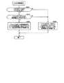
次に、TCP/IP受信処理回路5の動作について説明する。
まず、TCP/IP受信処理回路5内のフレーム解析処理部21の動作について説明する。図6は、フレーム解析処理部21の動作を示すフローチャートである。フレーム解析処理部21は、ネットワークインタフェース層のMACブリッジ回路4からフレームを受け取ると、図6に示す処理を開始する。Next, the operation of the TCP / IP
First, the operation of the frame
まず、フレーム解析処理部21は、MACブリッジ回路4から受け取ったフレームの末尾に付加されているフレームチェックシーケンス(Frame Check Sequence)内のCRC(Cyclic Redundancy Check)を用いて、フレームの検証を行う(ステップS11)。そして、フレーム解析処理部21は、エラーがあると判断した場合には処理をステップS13に移し、エラーが無いと判断した場合には処理をステップS14に移す(ステップS12)。 First, the frame
ステップS12にてフレームにエラーがあると判断した場合、フレーム解析処理部21は、フレームを廃棄し(ステップS13)、処理を終了する。 If it is determined in step S12 that there is an error in the frame, the frame
ステップS12にてフレームにエラーが無いと判断した場合、フレーム解析処理部21は、フレームのペイロードに格納されているパケットのプロトコルが所定のプロトコル(本実施形態においては、インターネット層のプロトコルがIP且つトランスポート層のプロトコルがTCP、インターネット層のプロトコルがIP且つトランスポート層のプロトコルがUDP、インターネット層のプロトコルがIP且つトランスポート層のプロトコルがICMP、インターネット層のプロトコルがARP、又は、インターネット層のプロトコルがRARPとする)であるか否かをチェックする。所定のプロトコルであるか否かは、パケットが図10〜図14に示すフォーマットに合致するか否かにより判断することが可能である。そして、フレーム解析処理部21は、フレームのペイロードに格納されているパケットのプロトコルが所定のプロトコルではない(例えば、フレームのペイロードに格納されているパケットのネットワーク層のプロトコルがIPバージョン6である場合や、フレームのペイロードに格納されているパケットのネットワーク層のプロトコルがIPではあるがトランスポート層のプロトコルがTCP、UDP、又は、ICMP以外のプロトコルである場合等)と判断した場合には処理をステップS15に移し、フレームのペイロードに格納されているパケットのプロトコルが所定のプロトコルであると判断した場合には処理をステップS16に移す(ステップS14)。 If it is determined in step S12 that there is no error in the frame, the frame
ステップS14にてフレームのペイロードに格納されているパケットのプロトコルが所定のプロトコルではないと判断した場合、フレーム解析処理部21は、フレームをそのままFIFOバッファメモリ23に書き込むとともに、フレーム及びプロトコルの解析結果を解析結果データ格納部22に書き込み(ステップS15)、処理を終了する。なお、ここでFIFOバッファメモリ23に書き込まれたフレームは、後に説明するように、メインメモリ9内のジャンクバッファに転送される。そして、ジャンクバッファに転送されたフレームは、CPUとソフトウェア(プログラム)でインターネット層及びトランスポート層の処理がされることとなる。 If it is determined in step S14 that the protocol of the packet stored in the payload of the frame is not a predetermined protocol, the frame
ステップS14にてフレームのペイロードに格納されているパケットのプロトコルが所定のプロトコルであると判断した場合、フレーム解析処理部21は、フレームのペイロードに格納されているパケット内の情報を用いて、パケットの検証を行う(ステップS16)。 When it is determined in step S14 that the protocol of the packet stored in the payload of the frame is a predetermined protocol, the frame
例えば、フレームのペイロードに格納されているパケットがIPパケット(図10参照)である場合、フレーム解析処理部21は、IPヘッダ内の「ヘッダ長」フィールド、「データグラム長」フィールド、及び、「ヘッダ・チェックサム」フィールドの値を用いて、フレームのペイロードに格納されているIPパケットの検証を行う。 For example, when the packet stored in the payload of the frame is an IP packet (see FIG. 10), the frame
また、フレームのペイロードに格納されているパケットがIPパケットであり且つIPパケットのペイロードに格納されているパケットがTCPパケット(図12参照)である場合、フレーム解析処理部21は、TCPヘッダ内の「チェックサム」フィールドの値を用いて、TCPパケットの検証を更に行う。 When the packet stored in the payload of the frame is an IP packet and the packet stored in the payload of the IP packet is a TCP packet (see FIG. 12), the frame
また、フレームのペイロードに格納されているパケットがIPパケットであり且つIPパケットのペイロードに格納されているパケットがUDPパケット(図13参照)である場合、フレーム解析処理部21は、UDPヘッダ内の「パケット長」フィールド及び「チェックサム」フィールドの値を用いて、UDPパケットの検証を更に行う。 When the packet stored in the payload of the frame is an IP packet and the packet stored in the payload of the IP packet is a UDP packet (see FIG. 13), the frame
また、フレームのペイロードに格納されているパケットがIPパケットであり且つIPパケットのペイロードに格納されているパケットがICMPパケット(図14参照)である場合、フレーム解析処理部21は、ICMPヘッダ内の「チェックサム」フィールドの値を用いて、ICMPパケットの検証を更に行う。 When the packet stored in the payload of the frame is an IP packet and the packet stored in the payload of the IP packet is an ICMP packet (see FIG. 14), the frame
再び図6を参照すると、フレーム解析処理部21は、パケットにエラーがあると判断した場合には処理をステップS18に移し、エラーが無いと判断した場合には処理をステップS19に移す(ステップS17)。 Referring to FIG. 6 again, the frame
ステップS17にてパケットにエラーがあると判断した場合、フレーム解析処理部21は、パケットを廃棄し(ステップS18)、処理を終了する。 If it is determined in step S17 that there is an error in the packet, the frame
ステップS17にてパケットにエラーが無いと判断した場合、フレーム解析処理部21は、パケットをFIFOバッファメモリ23に書き込むとともに、パケットの解析結果を解析結果データ格納部22に書き込み(ステップS19)、処理を終了する。 If it is determined in step S17 that there is no error in the packet, the frame
ここで、MACブリッジ回路4から受け取ったフレームのペイロードに格納されているパケットのプロトコルがARP又はRARPである場合、フレーム解析処理部21は、ARPパケット又はRARPパケットをFIFOバッファメモリ23に書き込む。また、MACブリッジ回路4から受け取ったフレームのペイロードに格納されているパケットのプロトコルがIPである場合、フレーム解析処理部21は、IPパケットのペイロードに格納されているパケット(本実施形態においては、TCPパケット、UDPパケット、又は、ICMPパケット)をFIFOバッファメモリ23に書き込む。 Here, when the protocol of the packet stored in the payload of the frame received from the
また、フレーム解析処理部21が解析結果データ格納部22に書き込む解析結果には、プロトコル(本実施形態においては、インターネット層のプロトコルがIP且つトランスポート層のプロトコルがTCP、インターネット層のプロトコルがIP且つトランスポート層のプロトコルがUDP、インターネット層のプロトコルがIP且つトランスポート層のプロトコルがICMP、インターネット層のプロトコルがARP、又は、インターネット層のプロトコルがRARP)、及びパケットのサイズが含まれる。さらに、MACブリッジ回路4から受け取ったフレームのペイロードに格納されているパケットのプロトコルが、インターネット層のプロトコルがIP且つトランスポート層のプロトコルがTCP又はインターネット層のプロトコルがIP且つトランスポート層のプロトコルがUDPである場合には、フレーム解析処理部21が解析結果データ格納部22に書き込む解析結果には、TCPヘッダ又はUDPヘッダのサイズと、TCPペイロード又はUDPペイロードのサイズと、通信端点を特定するための情報(ソース(自)IPアドレス、ソース(自)ポート番号、デスティネーション(相手)IPアドレス、及び、デスティネーション(相手)ポート番号)とが更に含まれる。なお、ソース(自)IPアドレス及びデスティネーション(相手)IPアドレスは、IPヘッダ(図10参照)に格納されており、ソース(自)ポート番号及びデスティネーション(相手)ポート番号)は、TCPヘッダ(図12参照)又はUDPヘッダ(図13参照)に格納されている。 The analysis result written by the frame
なお、フレーム解析処理部21が、CPU8のI/Oアドレス空間にマッピングされた複数の自動加算カウンタを具備していることとし、TCPの通信端点の開設時において、TCPの通信端点のシーケンス番号の初期値が、いずれかの自動加算カウンタにAPIにより書き込まれるようにしても良い。そして、フレーム解析処理部21が、TCPの通信端点宛てのパケットが格納されたフレームをMACブリッジ回路4から受け取った場合に、当該パケット中のシーケンス番号(図12参照)と自動加算カウンタの値とが一致するときには当該パケットをFIFOバッファメモリ23に書き込むとともに自動加算カウンタをインクリメントし、当該パケット中のシーケンス番号と自動加算カウンタの値とが一致しないときには当該パケットを廃棄するようにしても良い。TCPにおいては、シーケンス番号の一致性を検証することで、パケット到達の順序性と基本的な通信路の安全性を得る。一般に、1つの論理的データストリームは複数の受信パケットで構成される場合が多く、上記のように自動加算カウンタを具備することにより、パケット受信の可否をソフトウェアで行う必要をなくすことが可能となる。 It is assumed that the frame
次に、TCP/IP受信処理回路5内のDMA制御部24の動作について説明する。図7は、DMA制御部24の動作を示すフローチャートである。 Next, the operation of the
DMA制御部24は、解析結果データ格納部22に格納されている解析結果の内のプロトコルを参照し、FIFOバッファメモリ23に格納されているパケット等(パケット又はフレーム)がTCP又はUDPパケットであるか否かをチェックし、FIFOバッファメモリ23に格納されているパケット等がTCP又はUDPパケットであると判断した場合には処理をステップS22に移し、FIFOバッファメモリ23に格納されているパケット等がTCP又はUDPパケットではないと判断した場合には処理をステップS24に移す(ステップS21)。 The
ステップS21にてFIFOバッファメモリ23に格納されているパケット等がTCP又はUDPパケットであると判断した場合、DMA制御部24は、解析結果データ格納部22に格納されている解析結果の内の通信端点を特定するための情報(ソース(自)IPアドレス、ソース(自)ポート番号、デスティネーション(相手)IPアドレス、及び、デスティネーション(相手)ポート番号)を更に参照し、FIFOバッファメモリ23に格納されているTCP又はUDPパケットがいずれかの通信端点宛てのものであるか否かをチェックする。具体的には、DMA制御部24内のレジスタには、開設された通信端点を特定するための情報が格納されており(図2参照)、DMA制御部24は、解析結果データ格納部22に格納されている解析結果の内の通信端点を特定するための情報とレジスタの内容とを照合することにより、FIFOバッファメモリ23に格納されているTCP又はUDPパケットがいずれかの通信端点宛てのものであるか否かをチェックすることができる。または、DMA制御部24は、解析結果データ格納部22に格納されている解析結果の内の通信端点を特定するための情報と、メインメモリ9内の通信端点条件設定テーブル53の内容とを照合することにより、FIFOバッファメモリ23に格納されているTCP又はUDPパケットがいずれかの通信端点宛てのものであるか否かをチェックすることができる。そして、DMA制御部24は、FIFOバッファメモリ23に格納されているTCP又はUDPパケットがいずれかの通信端点宛てのものであると判断した場合には処理をステップS23に移し、FIFOバッファメモリ23に格納されているTCP又はUDPパケットがいずれの通信端点宛てのものでもないと判断した場合には処理をステップS24に移す(ステップS22)。 If it is determined in step S21 that the packet or the like stored in the
ステップS22にてFIFOバッファメモリ23に格納されているTCP又はUDPパケットがいずれかの通信端点宛てのものであると判断した場合、DMA制御部24は、FIFOバッファメモリ23に格納されているTCP又はUDPパケットをFIFOバッファメモリ23に格納されているTCP又はUDPパケットの宛先である通信端点のパケット格納領域にDMA転送するように、DMA処理部25を制御する(ステップS23)。 If it is determined in step S22 that the TCP or UDP packet stored in the
具体的には、FIFOバッファメモリ23に格納されているパケットが通信端点A宛てのTCPパケットである場合、DMA制御部24は、FIFOバッファメモリ23に格納されているTCPパケットをパケット格納領域31〜3m(図2参照)のいずれかに転送するようにDMA処理部25を制御する。なお、パケット格納領域31〜3mのいずれをDMA転送先にするかは、レジスタ内のポインタ(アドレス)からディスクリプタテーブル41〜4m内のパケット書込み可否情報格納領域(図3参照)を順次参照し、パケットの書込みが可能なパケット格納領域を探すことにより、決定することができる。また、DMA転送量(DMA転送データサイズ)は、解析結果データ格納部22に格納されているTCPヘッダサイズ及びTCPペイロードサイズを参照することにより、決定することができる。なお、FIFOバッファメモリ23に格納されているTCPパケットのヘッダ又はペイロードのサイズが転送先のヘッダ格納領域又はペイロード格納領域のサイズ(図3中のMHSフィールド又はMDSフィールドにより検知可能)を超えている場合には、DMA制御部24が、当該パケットのヘッダ又はペイロードの内の転送先のヘッダ格納領域又はペイロード格納領域に格納可能な部分のみをDMA転送し、当該パケットのヘッダ又はペイロードの内の転送先のヘッダ格納領域又はペイロード格納領域のサイズを超えている部分をDMA転送しないようにしても良い。 Specifically, when the packet stored in the
同様に、FIFOバッファメモリ23に格納されているパケットが通信端点B宛てのUDPパケットである場合、DMA制御部24は、FIFOバッファメモリ23に格納されているUDPパケットをパケット格納領域61〜6n(図2参照)のいずれかに転送するようにDMA処理部25を制御する。なお、パケット格納領域61〜6nのいずれをDMA転送先にするかは、レジスタ内のポインタ(アドレス)からディスクリプタテーブル71〜7n内のパケット書込み可否情報格納領域(図3参照)を順次参照し、パケットの書込みが可能なパケット格納領域を探すことにより、決定することができる。また、DMA転送量(DMA転送データサイズ)は、解析結果データ格納部22に格納されているUDPヘッダサイズ及びUDPペイロードサイズを参照することにより、決定することができる。なお、FIFOバッファメモリ23に格納されているUDPパケットのヘッダ又はペイロードのサイズが転送先のヘッダ格納領域又はペイロード格納領域のサイズ(図3中のMHSフィールド又はMDSフィールドにより検知可能)を超えている場合には、DMA制御部24が、当該パケットのヘッダ又はペイロードの内の転送先のヘッダ格納領域又はペイロード格納領域に格納可能な部分のみをDMA転送し、当該パケットのヘッダ又はペイロードの内の転送先のヘッダ格納領域又はペイロード格納領域のサイズを超えている部分をDMA転送しないようにしても良い。 Similarly, when the packet stored in the
一方、ステップS21にてFIFOバッファメモリ23に格納されているパケット等がTCP又はUDPパケットでないと判断した場合、又は、ステップS22にてFIFOバッファメモリ23に格納されているTCP又はUDPパケットがいずれの通信端点宛てのものでもないと判断した場合、DMA制御部24は、FIFOバッファメモリ23に格納されているパケット等をジャンクバッファにDMA転送するように、DMA処理部25を制御する(ステップS24)。DMA転送の終了後、DMA制御部24が、CPU8にパケット受信通知制御信号を出力し、CPU8がパケット等を読み出してソフトウェア(プログラム)でインターネット層及びトランスポート層の処理をすることが可能となる。 On the other hand, if it is determined in step S21 that the packet stored in the
なお、DMA制御部24が、CPU8のI/Oアドレス空間にマッピングされた複数の減算カウンタを具備していることとし、通信端点の開設時において、通信端点の論理的データストリームブロック(これは、ウィンドウバッファサイズであっても良い)の初期サイズが、いずれかの減算カウンタにAPIにより書き込まれるようにしても良い。そして、DMA制御部24が、ステップS23において、FIFOバッファメモリ23に格納されているTCP又はUDPパケットのペイロード部をFIFOバッファメモリ23に格納されているTCP又はUDPパケットの宛先である通信端点のペイロード格納領域にDMA転送する都度、通信端点に対応する減算カウンタの値をDMA転送量だけ減算するようにしても良い。そして、DMA制御部24が、減算カウンタが0になるまでCPU8にパケット受信通知制御信号を出力せず、減算カウンタが0になったときにCPU8にパケット受信通知制御信号を出力するようにすれば、アプリケーション層は複数の受信パケットで構成される固定長論理データストリームを一括して扱うことができ、ソフトウェアオーバーヘッドの削減(タスクスイッチングや割り込み発生回数の削減等)が可能となる。また、DMA制御部24が、ペイロードの内の減算カウンタの値を超える部分をDMA転送しないようにしても良い。 Note that the
以上説明したように、本実施形態によれば、ディスクリプタテーブルをリンクしておくことにより、TCP/IP受信処理回路5がTCP又はUDPの通信端点宛てのパケットをメインメモリ9内のパケット格納領域に転送することを簡素化でき、アプリケーション層が受信パケットの個数で定義される論理的データストリームブロックを容易に扱うことができる。 As described above, according to the present embodiment, by linking the descriptor tables, the TCP / IP
また、本実施形態によれば、TCP又はUDPの通信端点宛てのパケットのヘッダ及びペイロードを、メインメモリ9内に設けられたヘッダ格納領域及びペイロード格納領域に転送することができる。これにより、アプリケーション層は、1つの通信端点宛ての複数のパケットが存在する場合に、ヘッダを参照することなく、ペイロードのみを自在に利用することができる。このとき、複数のペイロード格納領域を連続するアドレスに配置しておけば、アプリケーション層が複数のペイロードを連続してアクセスすることが容易となる。 Further, according to the present embodiment, the header and payload of a packet addressed to a TCP or UDP communication end point can be transferred to a header storage area and a payload storage area provided in the main memory 9. As a result, the application layer can freely use only the payload without referring to the header when there are a plurality of packets addressed to one communication endpoint. At this time, if a plurality of payload storage areas are arranged at consecutive addresses, the application layer can easily access the plurality of payloads continuously.
また、本実施形態においては、TCP又はUDPの通信端点宛てのパケットのヘッダ又はペイロードのサイズが転送先のヘッダ格納領域又はペイロード格納領域のサイズを超えている場合には、当該パケットのヘッダ又はペイロードの内の転送先のヘッダ格納領域又はペイロード格納領域のサイズを超えている部分はDMA転送されない。従って、仮に第三者が不正なパケットをコンピュータ1に送信し、不正なパケットがTCP又はUDPの通信端点の設定条件に合致してしまった場合であっても、不正なパケットのヘッダ又はペイロードの内の転送先のヘッダ格納領域又はペイロード格納領域のサイズを超えている部分はDMA転送されず、不正なパケットによりOS、API、又は、アプリケーションプログラムのワークエリアが上書きされてしまうことがない。これにより、第三者によるクラッキング等を防止することが可能である。 In this embodiment, if the size of the header or payload of a packet addressed to a TCP or UDP communication endpoint exceeds the size of the header storage area or payload storage area of the transfer destination, the header or payload of the packet Of these, the part exceeding the size of the header storage area or payload storage area of the transfer destination is not DMA-transferred. Therefore, even if a third party sends an illegal packet to the
なお、本実施形態においては、ネットワークインタフェース層としてEthernet(登録商標)を用いることとしているが、他のものを用いるようにしても良い。また、アプリケーション層として、HTTP(Hyper Text Transfer Protocol)等、種々のものを用いることが可能である。 In the present embodiment, Ethernet (registered trademark) is used as the network interface layer, but another network interface layer may be used. Various applications such as HTTP (Hyper Text Transfer Protocol) can be used as the application layer.
本発明は、TCP/IP受信処理回路において利用可能である。このTCP/IP受信処理回路は、パーソナルコンピュータ、携帯電話装置、PDA、家庭電気製品(テレビジョン装置、冷蔵庫等)等に利用可能である。 The present invention can be used in a TCP / IP reception processing circuit. This TCP / IP reception processing circuit can be used for personal computers, mobile phone devices, PDAs, home appliances (television devices, refrigerators, etc.) and the like.
1 コンピュータ、 2 物理層処理回路、 3 MAC処理回路、 4 MACブリッジ回路、 5 TCP/IP受信処理回路、 6 TCP/IP送信処理回路、 7 インタフェース回路、 8 CPU、 9 メインメモリ、 10 HDD、 11 入力部、 12 表示部、 21 フレーム解析処理部、 22 解析結果データ格納部、 23 FIFOバッファメモリ、 24 DMA制御部、 25 DMA処理部 DESCRIPTION OF
Claims (11)
Translated fromJapanese前記メモリが、所定の通信端点宛ての複数のパケットをそれぞれ格納するための複数のパケット格納領域と、各々が有する第1のポインタによってリンクされている複数のディスクリプタテーブルであって、前記パケット格納領域を指し示すための第2のポインタ及び前記第2のポインタによって指し示される前記パケット格納領域にパケットを書き込むことが可能であるか否かを示すパケット書込み可否情報をそれぞれ有する前記複数のディスクリプタテーブルと、を含む通信端点情報領域を有しており、
下位レイヤから受け取ったフレームに格納されているパケットが前記所定の通信端点宛てのパケットである場合に、前記第1のポインタ及び前記パケット書込み可否情報を利用して前記複数のディスクリプタテーブルの中からパケットを書き込むことが可能な前記パケット格納領域を指し示す1つのディスクリプタテーブルを決定し、下位レイヤから受け取ったフレームに格納されているパケットを当該ディスクリプタテーブル内の前記第2のポインタによって指し示される前記パケット格納領域内に転送する、TCP/IP受信処理回路。A TCP / IP (Transmission Control Protocol / Internet Protocol) reception processing circuit for transferring a packet stored in a frame received from a lower layer to a memory accessible by the upper layer,
The memory includes a plurality of packet storage areas for storing a plurality of packets addressed to a predetermined communication endpoint, and a plurality of descriptor tables linked by a first pointer included in each of the packet storage areas. A plurality of descriptor tables each having a second pointer for indicating packet and packet write enable / disable information indicating whether or not a packet can be written in the packet storage area indicated by the second pointer; Communication endpoint information area including
When a packet stored in a frame received from a lower layer is a packet addressed to the predetermined communication end point, a packet is selected from the plurality of descriptor tables using the first pointer and the packet write enable / disable information. The packet storage pointed to by the second pointer in the descriptor table is determined for one descriptor table that points to the packet storage area where the packet can be written, and the packet stored in the frame received from the lower layer is determined. A TCP / IP reception processing circuit that transfers to the area.
前記第2のポインタが、前記ヘッダ格納領域を指し示す第3のポインタと、前記ペイロード格納領域を指し示す第4のポインタと、を含んでおり、
下位レイヤから受け取ったフレームに格納されているパケットが前記所定の通信端点宛てのパケットである場合に、前記第1のポインタ及び前記パケット書き込み可否情報を利用して前記複数のディスクリプタテーブルの中からパケットを書き込むことが可能な前記パケット格納領域を指し示す1つのディスクリプタテーブルを決定し、下位レイヤから受け取ったフレームに格納されているパケットのヘッダを当該ディスクリプタテーブル内の前記第3のポインタによって指し示される前記ヘッダ格納領域内に転送し、下位レイヤから受け取ったフレームに格納されているパケットのペイロードを当該ディスクリプタテーブル内の前記第4のポインタによって指し示される前記ペイロード格納領域内に転送する、請求項1記載のTCP/IP受信処理回路。Each of the plurality of packet storage areas includes a header storage area for storing a header of the packet and a payload storage area for storing a payload of the packet;
The second pointer includes a third pointer that points to the header storage area and a fourth pointer that points to the payload storage area;
When a packet stored in a frame received from a lower layer is a packet addressed to the predetermined communication end point, a packet is selected from the plurality of descriptor tables using the first pointer and the packet write enable / disable information. Is determined, and a header of a packet stored in a frame received from a lower layer is indicated by the third pointer in the descriptor table. 2. The packet payload stored in a frame received from a lower layer is transferred into the header storage area, and the payload of the packet stored in the descriptor table is transferred to the payload storage area indicated by the fourth pointer. TCP / IP Signal processing circuit.
下位レイヤから受け取ったフレームに格納されているパケットが前記所定の通信端点宛てのパケットである場合に、前記第1のポインタ及び前記パケット書き込み可否情報を利用して前記複数のディスクリプタテーブルの中からパケットを書き込むことが可能な前記パケット格納領域を指し示す1つのディスクリプタテーブルを決定し、当該ディスクリプタテーブル内の前記ヘッダ格納領域サイズ情報によって表されるサイズより下位レイヤから受け取ったフレームに格納されているパケットのヘッダのサイズが大きいときに、下位レイヤから受け取ったフレームに格納されているパケットのヘッダの内の当該ディスクリプタテーブル内の前記ヘッダ格納領域に格納可能な部分を当該ディスクリプタテーブル内の前記ヘッダ格納領域に転送し、当該ディスクリプタテーブル内の前記ペイロード格納領域サイズ情報によって表されるサイズより下位レイヤから受け取ったフレームに格納されているパケットのペイロードのサイズが大きいときに、下位レイヤから受け取ったフレームに格納されているパケットのペイロードの内の当該ディスクリプタテーブル内の前記ペイロード格納領域に格納可能な部分を当該ディスクリプタテーブル内の前記ペイロード格納領域に転送する、請求項2又は3記載のTCP/IP受信処理回路。Each of the plurality of descriptor tables includes header storage area size information indicating a size of a header that can be stored in the header storage area, and payload storage area size information indicating a size of the payload that can be stored in the payload storage area. In addition,
When a packet stored in a frame received from a lower layer is a packet addressed to the predetermined communication end point, a packet is selected from the plurality of descriptor tables using the first pointer and the packet write enable / disable information. One descriptor table indicating the packet storage area in which the packet can be written is determined, and the packet stored in the frame received from the lower layer than the size represented by the header storage area size information in the descriptor table is determined. When the size of the header is large, a portion of the packet header stored in the frame received from the lower layer that can be stored in the header storage area in the descriptor table is stored in the header storage area in the descriptor table. Forward A packet stored in a frame received from a lower layer when the payload size of the packet stored in the frame received from the lower layer is larger than the size represented by the payload storage area size information in the descriptor table 4. The TCP / IP reception processing circuit according to claim 2, wherein a portion that can be stored in the payload storage area of the descriptor table in the payload table is transferred to the payload storage area of the descriptor table. 5.
前記メモリが、前記所定の通信端点宛てのRSTパケットを格納するためのRSTパケット格納領域と、前記RSTパケット格納領域を指し示すためのポインタを有するRSTディスクリプタテーブルと、を更に有し、
下位レイヤから受け取ったフレームに格納されているパケットが前記所定の通信端点宛てのRSTパケットである場合に、前記RSTディスクリプタテーブル内の前記ポインタによって指し示される前記RSTパケット格納領域内に前記RSTパケットを転送する、請求項1〜5のいずれか1項記載のTCP/IP受信処理回路。When the predetermined communication endpoint is a TCP (Transmission Control Protocol) communication endpoint,
The memory further includes an RST packet storage area for storing an RST packet addressed to the predetermined communication endpoint, and an RST descriptor table having a pointer for pointing to the RST packet storage area;
When the packet stored in the frame received from the lower layer is an RST packet addressed to the predetermined communication endpoint, the RST packet is stored in the RST packet storage area pointed to by the pointer in the RST descriptor table. The TCP / IP reception processing circuit according to claim 1, wherein the TCP / IP reception processing circuit transfers.
下位レイヤから受け取ったフレームに格納されているパケットが前記所定の通信端点宛てのパケットである場合に、前記第1のポインタ及び前記パケット書込み可否情報を利用して前記複数のディスクリプタテーブルの中からパケットを書き込むことが可能な前記パケット格納領域を指し示す1つのディスクリプタテーブルを決定し、下位レイヤから受け取ったフレームに格納されているパケットを当該ディスクリプタテーブル内の前記第2のポインタによって指し示される前記パケット格納領域内に転送するとともに、下位レイヤから受け取ったフレーム又は下位レイヤから受け取ったフレームに格納されているパケットの解析結果を当該ディスクリプタテーブル内の前記解析結果格納領域に書き込む、請求項1〜7のいずれか1項記載のTCP/IP受信処理回路。Each of the plurality of descriptor tables further includes an analysis result storage area for storing an analysis result of a packet received from a frame received from a lower layer or a frame received from a lower layer,
When a packet stored in a frame received from a lower layer is a packet addressed to the predetermined communication end point, a packet is selected from the plurality of descriptor tables using the first pointer and the packet write enable / disable information. The packet storage pointed to by the second pointer in the descriptor table is determined for one descriptor table that points to the packet storage area where the packet can be written, and the packet stored in the frame received from the lower layer is determined. Either of the transfer results in the area and the analysis result of the packet stored in the frame received from the lower layer or the frame received from the lower layer are written in the analysis result storage area in the descriptor table. Or 1 CP / IP reception processing circuit.
下位レイヤから受け取ったフレームに格納されているパケットが前記複数の通信端点のいずれかの通信端点宛てのパケットである場合に、前記複数の通信端点情報領域の中の当該パケットの宛先である通信端点に対応する通信端点情報領域の中のディスクリプタテーブル内で指し示されるパケット格納領域に当該パケットを書き込む、請求項1〜8のいずれか1項記載のTCP/IP受信処理回路。The memory has a plurality of communication endpoint information areas respectively corresponding to a plurality of communication endpoints;
When the packet stored in the frame received from the lower layer is a packet addressed to any one of the plurality of communication end points, the communication end point that is the destination of the packet in the plurality of communication end point information areas The TCP / IP reception processing circuit according to claim 1, wherein the packet is written in a packet storage area indicated in a descriptor table in a communication endpoint information area corresponding to.
下位レイヤから受け取ったフレームに格納されているパケットのプロトコルが所定のプロトコルでない場合又は下位レイヤから受け取ったフレームに格納されているパケットが前記複数の通信端点のいずれ宛てでもないパケットである場合に、下位レイヤから受け取ったフレームに格納されているパケットのプロトコルが所定のプロトコルでない場合における当該フレーム又は下位レイヤから受け取ったフレームに格納されているパケットが前記複数の通信端点のいずれ宛てでもないパケットである場合における当該パケットを前記第2の通信端点情報領域の中のディスクリプタテーブル内で指し示されるパケット格納領域に転送する、請求項9記載のTCP/IP受信処理回路。When the protocol of the packet stored in the frame received from the lower layer is not a predetermined protocol, the packet stored in the frame or the frame received from the lower layer is addressed to any of the plurality of communication endpoints. A second communication end point information area for storing the packet in the case of a non-existing packet,
When the protocol of the packet stored in the frame received from the lower layer is not a predetermined protocol, or when the packet stored in the frame received from the lower layer is a packet not addressed to any of the plurality of communication endpoints, When the protocol of the packet stored in the frame received from the lower layer is not a predetermined protocol, the packet stored in the frame or the frame received from the lower layer is a packet not addressed to any of the plurality of communication end points. The TCP / IP reception processing circuit according to claim 9, wherein the packet in the case is transferred to a packet storage area indicated in a descriptor table in the second communication endpoint information area.
Priority Applications (2)
| Application Number | Priority Date | Filing Date | Title |
|---|---|---|---|
| JP2005147618AJP2006325054A (en) | 2005-05-20 | 2005-05-20 | TCP / IP reception processing circuit and semiconductor integrated circuit having the same |
| US11/419,042US20060265517A1 (en) | 2005-05-20 | 2006-05-18 | Tcp/ip reception process circuit and semiconductor integrated cirtuit having the same |
Applications Claiming Priority (1)
| Application Number | Priority Date | Filing Date | Title |
|---|---|---|---|
| JP2005147618AJP2006325054A (en) | 2005-05-20 | 2005-05-20 | TCP / IP reception processing circuit and semiconductor integrated circuit having the same |
Publications (1)
| Publication Number | Publication Date |
|---|---|
| JP2006325054Atrue JP2006325054A (en) | 2006-11-30 |
Family
ID=37449614
Family Applications (1)
| Application Number | Title | Priority Date | Filing Date |
|---|---|---|---|
| JP2005147618AWithdrawnJP2006325054A (en) | 2005-05-20 | 2005-05-20 | TCP / IP reception processing circuit and semiconductor integrated circuit having the same |
Country Status (2)
| Country | Link |
|---|---|
| US (1) | US20060265517A1 (en) |
| JP (1) | JP2006325054A (en) |
Families Citing this family (17)
| Publication number | Priority date | Publication date | Assignee | Title |
|---|---|---|---|---|
| US7447795B2 (en) | 2001-04-11 | 2008-11-04 | Chelsio Communications, Inc. | Multi-purpose switching network interface controller |
| US7724658B1 (en) | 2005-08-31 | 2010-05-25 | Chelsio Communications, Inc. | Protocol offload transmit traffic management |
| US7616563B1 (en) | 2005-08-31 | 2009-11-10 | Chelsio Communications, Inc. | Method to implement an L4-L7 switch using split connections and an offloading NIC |
| US7660306B1 (en) | 2006-01-12 | 2010-02-09 | Chelsio Communications, Inc. | Virtualizing the operation of intelligent network interface circuitry |
| US8935406B1 (en) | 2007-04-16 | 2015-01-13 | Chelsio Communications, Inc. | Network adaptor configured for connection establishment offload |
| US8060644B1 (en) | 2007-05-11 | 2011-11-15 | Chelsio Communications, Inc. | Intelligent network adaptor with end-to-end flow control |
| US8589587B1 (en)* | 2007-05-11 | 2013-11-19 | Chelsio Communications, Inc. | Protocol offload in intelligent network adaptor, including application level signalling |
| JP4548524B2 (en)* | 2008-07-29 | 2010-09-22 | ソニー株式会社 | COMMUNICATION DEVICE, PROGRAM, COMMUNICATION METHOD, AND COMMUNICATION SYSTEM |
| RU2016111141A (en) | 2013-08-29 | 2017-10-02 | Сейко Эпсон Корпорейшн | TRANSMISSION SYSTEM, TRANSMISSION DEVICE AND METHOD OF DATA TRANSFER |
| US9226217B2 (en)* | 2014-04-17 | 2015-12-29 | Twilio, Inc. | System and method for enabling multi-modal communication |
| CN104052676B (en)* | 2014-06-13 | 2017-12-05 | 华为技术有限公司 | A kind of data processing method of transmission path device and transmission path |
| US10275595B2 (en)* | 2016-09-29 | 2019-04-30 | Trap Data Security Ltd. | System and method for characterizing malware |
| CN107995184B (en)* | 2017-11-28 | 2020-10-30 | 航信德利信息系统(上海)有限公司 | Connector and communication method using same |
| US10848424B2 (en)* | 2019-03-26 | 2020-11-24 | Wipro Limited | Method and system for improving switching capacity of software-based switches in access networks |
| US11681804B2 (en) | 2020-03-09 | 2023-06-20 | Commvault Systems, Inc. | System and method for automatic generation of malware detection traps |
| US11689648B2 (en)* | 2021-03-11 | 2023-06-27 | Xilinx, Inc. | Network interface device |
| US20240056481A1 (en) | 2022-08-09 | 2024-02-15 | Commvault Systems, Inc. | Data storage management system integrating cyber threat deception |
Family Cites Families (5)
| Publication number | Priority date | Publication date | Assignee | Title |
|---|---|---|---|---|
| US5841771A (en)* | 1995-07-07 | 1998-11-24 | Northern Telecom Limited | Telecommunications switch apparatus and method for time switching |
| US7447197B2 (en)* | 2001-10-18 | 2008-11-04 | Qlogic, Corporation | System and method of providing network node services |
| US7177311B1 (en)* | 2002-06-04 | 2007-02-13 | Fortinet, Inc. | System and method for routing traffic through a virtual router-based network switch |
| US7944920B2 (en)* | 2002-06-11 | 2011-05-17 | Pandya Ashish A | Data processing system using internet protocols and RDMA |
| US20060104295A1 (en)* | 2004-11-16 | 2006-05-18 | Secure64 Software Corporation | Queued, asynchronous communication architecture interface |
- 2005
- 2005-05-20JPJP2005147618Apatent/JP2006325054A/ennot_activeWithdrawn
- 2006
- 2006-05-18USUS11/419,042patent/US20060265517A1/ennot_activeAbandoned
Also Published As
| Publication number | Publication date |
|---|---|
| US20060265517A1 (en) | 2006-11-23 |
Similar Documents
| Publication | Publication Date | Title |
|---|---|---|
| US20060265517A1 (en) | Tcp/ip reception process circuit and semiconductor integrated cirtuit having the same | |
| US11695669B2 (en) | Network interface device | |
| TWI332150B (en) | Processing data for a tcp connection using an offload unit | |
| US6735647B2 (en) | Data reordering mechanism for high performance networks | |
| US6526446B1 (en) | Hardware only transmission control protocol segmentation for a high performance network interface card | |
| US7561573B2 (en) | Network adaptor, communication system and communication method | |
| US6449656B1 (en) | Storing a frame header | |
| US11979340B2 (en) | Direct data placement | |
| US8311059B2 (en) | Receive coalescing and automatic acknowledge in network interface controller | |
| CN100479437C (en) | Method of parsing a packet header and computer system | |
| US20060067346A1 (en) | System and method for placement of RDMA payload into application memory of a processor system | |
| US20050223118A1 (en) | System and method for placement of sharing physical buffer lists in RDMA communication | |
| US7283549B2 (en) | Method for increasing the transmit and receive efficiency of an embedded ethernet controller | |
| US20080256271A1 (en) | Methods and apparatus for reducing storage usage in devices | |
| US7551638B2 (en) | Network interface with transmit frame descriptor reuse | |
| US20060268867A1 (en) | TCP/IP reception processing circuit and semiconductor integrated circuit implementing the same | |
| US6567859B1 (en) | Device for translating medium access control dependent descriptors for a high performance network | |
| US7016354B2 (en) | Packet-based clock signal | |
| US20020078246A1 (en) | Method and system for network protocol processing | |
| Douglas et al. | Seekable sockets: a mechanism to reduce copy overheads in TCP-based messaging |
Legal Events
| Date | Code | Title | Description |
|---|---|---|---|
| A761 | Written withdrawal of application | Free format text:JAPANESE INTERMEDIATE CODE: A761 Effective date:20070122 |