JP2006323219A - Lens unit and imaging apparatus having the same - Google Patents
Lens unit and imaging apparatus having the sameDownload PDFInfo
- Publication number
- JP2006323219A JP2006323219AJP2005147302AJP2005147302AJP2006323219AJP 2006323219 AJP2006323219 AJP 2006323219AJP 2005147302 AJP2005147302 AJP 2005147302AJP 2005147302 AJP2005147302 AJP 2005147302AJP 2006323219 AJP2006323219 AJP 2006323219A
- Authority
- JP
- Japan
- Prior art keywords
- lens group
- lens
- optical system
- group
- object side
- Prior art date
- Legal status (The legal status is an assumption and is not a legal conclusion. Google has not performed a legal analysis and makes no representation as to the accuracy of the status listed.)
- Pending
Links
- 238000003384imaging methodMethods0.000titleclaimsabstractdescription62
- 230000003287optical effectEffects0.000claimsabstractdescription260
- 230000003247decreasing effectEffects0.000claimsdescription10
- 230000004075alterationEffects0.000description77
- 238000010586diagramMethods0.000description53
- 201000009310astigmatismDiseases0.000description22
- 230000000694effectsEffects0.000description17
- 238000013461designMethods0.000description16
- 230000005499meniscusEffects0.000description16
- 238000012937correctionMethods0.000description11
- 239000006059cover glassSubstances0.000description10
- 238000012545processingMethods0.000description10
- 230000005540biological transmissionEffects0.000description7
- 230000007423decreaseEffects0.000description7
- 230000007246mechanismEffects0.000description7
- 238000010276constructionMethods0.000description6
- 230000006870functionEffects0.000description6
- 238000000034methodMethods0.000description5
- 230000008859changeEffects0.000description4
- 239000011521glassSubstances0.000description3
- 239000000853adhesiveSubstances0.000description2
- 230000001070adhesive effectEffects0.000description2
- 230000004907fluxEffects0.000description2
- 230000004044responseEffects0.000description2
- 239000004065semiconductorSubstances0.000description2
- GGCZERPQGJTIQP-UHFFFAOYSA-Nsodium;9,10-dioxoanthracene-2-sulfonic acidChemical compound[Na+].C1=CC=C2C(=O)C3=CC(S(=O)(=O)O)=CC=C3C(=O)C2=C1GGCZERPQGJTIQP-UHFFFAOYSA-N0.000description2
- 230000009471actionEffects0.000description1
- 239000008186active pharmaceutical agentSubstances0.000description1
- 238000013459approachMethods0.000description1
- 230000000295complement effectEffects0.000description1
- 238000006073displacement reactionMethods0.000description1
- 239000000428dustSubstances0.000description1
- 238000012905input functionMethods0.000description1
- 239000004973liquid crystal related substanceSubstances0.000description1
- 229910044991metal oxideInorganic materials0.000description1
- 150000004706metal oxidesChemical class0.000description1
- 238000012986modificationMethods0.000description1
- 230000004048modificationEffects0.000description1
Images


Classifications
- G—PHYSICS
- G02—OPTICS
- G02B—OPTICAL ELEMENTS, SYSTEMS OR APPARATUS
- G02B7/00—Mountings, adjusting means, or light-tight connections, for optical elements
- G02B7/02—Mountings, adjusting means, or light-tight connections, for optical elements for lenses
- G02B7/04—Mountings, adjusting means, or light-tight connections, for optical elements for lenses with mechanism for focusing or varying magnification
- G02B7/10—Mountings, adjusting means, or light-tight connections, for optical elements for lenses with mechanism for focusing or varying magnification by relative axial movement of several lenses, e.g. of varifocal objective lens
- G02B7/102—Mountings, adjusting means, or light-tight connections, for optical elements for lenses with mechanism for focusing or varying magnification by relative axial movement of several lenses, e.g. of varifocal objective lens controlled by a microcomputer
- G—PHYSICS
- G02—OPTICS
- G02B—OPTICAL ELEMENTS, SYSTEMS OR APPARATUS
- G02B15/00—Optical objectives with means for varying the magnification
- G02B15/14—Optical objectives with means for varying the magnification by axial movement of one or more lenses or groups of lenses relative to the image plane for continuously varying the equivalent focal length of the objective
- G02B15/144—Optical objectives with means for varying the magnification by axial movement of one or more lenses or groups of lenses relative to the image plane for continuously varying the equivalent focal length of the objective having four groups only
- G02B15/1441—Optical objectives with means for varying the magnification by axial movement of one or more lenses or groups of lenses relative to the image plane for continuously varying the equivalent focal length of the objective having four groups only the first group being positive
- G02B15/144113—Optical objectives with means for varying the magnification by axial movement of one or more lenses or groups of lenses relative to the image plane for continuously varying the equivalent focal length of the objective having four groups only the first group being positive arranged +-++
- G—PHYSICS
- G02—OPTICS
- G02B—OPTICAL ELEMENTS, SYSTEMS OR APPARATUS
- G02B15/00—Optical objectives with means for varying the magnification
- G02B15/14—Optical objectives with means for varying the magnification by axial movement of one or more lenses or groups of lenses relative to the image plane for continuously varying the equivalent focal length of the objective
- G02B15/144—Optical objectives with means for varying the magnification by axial movement of one or more lenses or groups of lenses relative to the image plane for continuously varying the equivalent focal length of the objective having four groups only
- G02B15/1445—Optical objectives with means for varying the magnification by axial movement of one or more lenses or groups of lenses relative to the image plane for continuously varying the equivalent focal length of the objective having four groups only the first group being negative
- G02B15/144515—Optical objectives with means for varying the magnification by axial movement of one or more lenses or groups of lenses relative to the image plane for continuously varying the equivalent focal length of the objective having four groups only the first group being negative arranged -+++
- G—PHYSICS
- G02—OPTICS
- G02B—OPTICAL ELEMENTS, SYSTEMS OR APPARATUS
- G02B15/00—Optical objectives with means for varying the magnification
- G02B15/14—Optical objectives with means for varying the magnification by axial movement of one or more lenses or groups of lenses relative to the image plane for continuously varying the equivalent focal length of the objective
- G02B15/16—Optical objectives with means for varying the magnification by axial movement of one or more lenses or groups of lenses relative to the image plane for continuously varying the equivalent focal length of the objective with interdependent non-linearly related movements between one lens or lens group, and another lens or lens group
- G02B15/177—Optical objectives with means for varying the magnification by axial movement of one or more lenses or groups of lenses relative to the image plane for continuously varying the equivalent focal length of the objective with interdependent non-linearly related movements between one lens or lens group, and another lens or lens group having a negative front lens or group of lenses
- G—PHYSICS
- G02—OPTICS
- G02B—OPTICAL ELEMENTS, SYSTEMS OR APPARATUS
- G02B5/00—Optical elements other than lenses
- G02B5/04—Prisms
Landscapes
- Physics & Mathematics (AREA)
- General Physics & Mathematics (AREA)
- Optics & Photonics (AREA)
- Engineering & Computer Science (AREA)
- General Engineering & Computer Science (AREA)
- Nonlinear Science (AREA)
- Lenses (AREA)
Abstract
Description
Translated fromJapanese本発明は、例えば変倍光学系を含むレンズユニット、およびこのレンズユニットを含む撮像装置に関するものである。 The present invention relates to a lens unit including, for example, a variable magnification optical system, and an imaging apparatus including the lens unit.
近年、光学像を電気信号に変換するCCD(Charge Coupled Device)等の撮像素子を用いたデジタルカメラが普及しつつある。そして、このようなデジタルカメラも、銀塩フィルムを用いたカメラ(銀塩カメラ)同様に、小型化(コンパクト化)・構成の簡素化が求められている。 In recent years, digital cameras using an image sensor such as a CCD (Charge Coupled Device) that converts an optical image into an electric signal are becoming widespread. Such a digital camera is also required to be downsized (compact) and simplified in configuration, like a camera using a silver salt film (silver salt camera).
デジタルカメラ等に用いられる変倍可能な光学系(変倍光学系;ズームレンズ等)は、正・負・正・正のパワー(屈折力)になったレンズ群を備えるものが多い。そして、このような変倍光学系は、構成の簡素化を図るため、変倍(ズーミング)等のときに、物体側に最も近い第1レンズ群を不動にしている場合がある(例えば特許文献1)。 An optical system (variable optical system; zoom lens, etc.) capable of zooming used in a digital camera or the like often includes a lens group having positive, negative, positive, and positive power (refractive power). In order to simplify the configuration of such a variable magnification optical system, the first lens group closest to the object side may be fixed during zooming or the like (for example, Patent Documents). 1).
しかし、特許文献1のズームレンズのように、第1レンズ群を不動にしてしまうと、ズームレンズの全長やレンズ径(例えば前玉レンズの径)が大きくなりやすい。このような傾向を抑制させるために、第1レンズ群を移動させる変倍方式も存在する。しかし、この方式は、ズームレンズの全長やレンズ径を小さくするものの、構成の複雑化を招いてしまう。 However, if the first lens unit is not moved as in the zoom lens disclosed in
そこで、特許文献1のズームレンズは、第1レンズ群を不動にする一方、像側に最も近い第4レンズ群を可動にする変倍方式を採用したり、直角プリズムを第1レンズ群内に設ることで光軸を屈曲させたりして、レンズ径等のコンパクト化を図っている。
しかしながら、第1レンズ群を不動にする一方、像側に最も近い第4レンズ群を可動にする変倍方式だけでは、レンズ径等のコンパクト化に限界がある。 However, there is a limit to downsizing the lens diameter or the like only with the variable magnification system that makes the first lens group stationary while moving the fourth lens group closest to the image side.
本発明は、このような現状を鑑みてなされてものであって、その目的は、レンズ群におけるレンズの径(レンズ径)や光学プリズムをコンパクトにしたレンズユニット、およびこのレンズユニットを備えたコンパクトな撮像装置を提供することを目的とする。 The present invention has been made in view of such a current situation, and an object of the present invention is to provide a lens unit in which a lens diameter (lens diameter) and an optical prism in a lens group are compact, and a compact including the lens unit. It is an object to provide a simple image pickup apparatus.
本発明のレンズユニットは、複数のレンズ群から成る変倍光学系と、この変倍光学系を経た光を受光する撮像素子と、を含んでいる。そして、複数のレンズ群において、物体側に最も近いレンズ群である物体側レンズ群は、光軸を変更させる光軸変更部材を含んでいる。そして、本発明のレンズユニットでは、変倍の場合、物体側レンズ群は不動である一方、撮像素子は光軸に沿って移動することを特徴としている。 The lens unit of the present invention includes a variable power optical system composed of a plurality of lens groups, and an image sensor that receives light that has passed through the variable power optical system. In the plurality of lens groups, the object side lens group that is the lens group closest to the object side includes an optical axis changing member that changes the optical axis. In the lens unit of the present invention, in the case of zooming, the object side lens unit is not moved, while the image sensor moves along the optical axis.
このように撮像素子が移動する一方、レンズ群が不動な変倍は、撮像素子が不動な一方、レンズ群が可動する変倍と同様な構成になる。なぜなら、撮像素子が不動な一方でレンズ群が移動することと、撮像素子が移動する一方でレンズ群が不動であることとは、相対的には、同義(等価)といえるためである。 In this way, the magnification change in which the image sensor moves while the lens group does not move has the same configuration as the magnification change in which the image element does not move while the lens group moves. This is because the movement of the lens group while the image sensor is stationary and the movement of the lens group while the image sensor is moved are relatively synonymous (equivalent).
すると、本発明のレンズユニットは、撮像素子を移動させることで変倍する。そのため、物体側レンズ群が、撮影対象(物体側)に向かって繰り出す必要は低くなる。その結果、比較的広い画角の光を受光する必要がなくなり、不動である物体側レンズ群を構成するレンズの径(前玉径等)が比較的縮小する。 Then, the lens unit of the present invention performs zooming by moving the image sensor. Therefore, it is less necessary for the object side lens group to be extended toward the photographing target (object side). As a result, it is not necessary to receive light having a relatively wide angle of view, and the diameter of the lens constituting the object-side lens group that does not move (front lens diameter, etc.) is relatively reduced.
その上、本発明のレンズユニットでは、不動なレンズ群である物体側レンズ群に、光軸変更部材が設けられている。したがって、この光軸変更部材(光学プリズムや反射ミラー等)も、比較的広い画角の光を受光する必要がなくなる。したがって、光軸変更部材のサイズが、比較的縮小する。 In addition, in the lens unit of the present invention, the optical axis changing member is provided in the object side lens group which is an immovable lens group. Therefore, this optical axis changing member (such as an optical prism or a reflecting mirror) does not need to receive light having a relatively wide angle of view. Therefore, the size of the optical axis changing member is relatively reduced.
以上のように、本発明のレンズユニットは、不動になった物体側レンズ群に含まれるレンズの径(前玉径等)や光軸変更部材を比較的コンパクトにしている。 As described above, in the lens unit of the present invention, the diameter of the lens (front lens diameter, etc.) and the optical axis changing member included in the object-side lens group that has become stationary are made relatively compact.
また、本発明のレンズユニットは、物体側に最も近いレンズ群である物体側レンズ群、像側に最も近いレンズ群である像側レンズ群、および物体側レンズ群と像側レンズ群との間に位置する少なくとも1つ以上のレンズ群から成る中間レンズ群、を含む複数のレンズ群を備える変倍光学系と、この変倍光学系を経た光を受光する撮像素子と、を含んでいる。 The lens unit of the present invention includes an object side lens group that is the lens group closest to the object side, an image side lens group that is the lens group closest to the image side, and a space between the object side lens group and the image side lens group. A variable magnification optical system including a plurality of lens groups including an intermediate lens group composed of at least one lens group positioned in the lens, and an imaging element that receives light that has passed through the variable magnification optical system.
さらに、中間レンズ群における少なくとも1つのレンズ群は、光軸を変更させる光軸変更部材を含んでいる。そして、本発明のレンズユニットでは、変倍の場合、光軸変更部材を含んだレンズ群が不動である一方、上記撮像素子は光軸に沿って移動することを特徴としている。 Furthermore, at least one lens group in the intermediate lens group includes an optical axis changing member that changes the optical axis. In the lens unit of the present invention, in the case of zooming, the lens group including the optical axis changing member does not move, while the imaging element moves along the optical axis.
上記同様に、本発明のレンズユニットは、撮像素子を移動させることで変倍する。そのため、中間レンズ群が、撮影対象(物体側)に向かって繰り出す必要は低くなる。その結果、比較的広い画角の光を受光する必要がなくなり、中間レンズ群における不動なレンズ群を構成するレンズの径が比較的縮小する。 Similarly to the above, the lens unit of the present invention performs zooming by moving the image sensor. For this reason, it is less necessary for the intermediate lens group to be extended toward the photographing target (object side). As a result, there is no need to receive light having a relatively wide angle of view, and the diameter of the lens constituting the stationary lens group in the intermediate lens group is relatively reduced.
その上、本発明のレンズユニットでは、中間レンズ群における不動なレンズ群に、光軸変更部材が設けられている。したがって、光軸変更部材のサイズも比較的縮小する。 In addition, in the lens unit of the present invention, the optical axis changing member is provided in the stationary lens group in the intermediate lens group. Accordingly, the size of the optical axis changing member is also relatively reduced.
なお、物体側から離れた中間レンズ群の入射してくる光は、物体側レンズ群に入射してくる光に比べて小さい光束径の光になっていることがある。すると、この不動なレンズ群に設けられた光軸変更部材も、小さい光束径の光を受光するだけでよい。したがって、一層、光軸変更部材のサイズが縮小するといえる。 Note that the light incident on the intermediate lens group away from the object side may be light having a smaller luminous flux diameter than the light incident on the object side lens group. Then, the optical axis changing member provided in this stationary lens group only needs to receive light with a small luminous flux diameter. Therefore, it can be said that the size of the optical axis changing member is further reduced.
また、本発明のレンズユニットでは、物体側レンズ群および中間レンズ群の少なくとも1つのレンズ群は、各々、光軸を変更させる光軸変更部材を含んでおり、変倍の場合、光軸変更部材を備えた物体側レンズ群および中間レンズ群は不動である一方、撮像素子は光軸に沿って移動するようになっていてもよい。 In the lens unit of the present invention, at least one lens group of the object side lens group and the intermediate lens group each includes an optical axis changing member that changes the optical axis. While the object side lens group and the intermediate lens group provided with are stationary, the imaging device may be moved along the optical axis.
このようなレンズユニットであれば、物体側レンズ群におけるレンズの径、中間レンズ群における不動なレンズ群のレンズの径、および両者(物体側レンズ群・中間レンズ群における不動なレンズ群)に設けられた各々の光軸変更部材のサイズが縮小化する。 In such a lens unit, the lens diameter in the object side lens group, the lens diameter of the immovable lens group in the intermediate lens group, and both (the immovable lens group in the object side lens group and the intermediate lens group) are provided. The size of each optical axis changing member is reduced.
以上のように、本発明のレンズユニットは、不動になったレンズ群(物体側レンズ群・中間レンズ群における不動なレンズ群)に含まれるレンズの径(前玉径等)や光軸変更部材を比較的コンパクトにしている。 As described above, the lens unit of the present invention includes the lens diameter (front lens diameter, etc.) and the optical axis changing member included in the lens group that is stationary (the stationary lens group in the object side lens group and the intermediate lens group). Is relatively compact.
なお、本発明のレンズユニットでは、像側レンズ群と撮像素子とが、一体で移動してもよい。このような構成にするために、例えば像側レンズ群と撮像素子とが一体化させると、変倍用に、像側レンズ群専用の移動用駆動源や、撮像素子専用の移動用駆動源が不要になる。また、像側レンズ群と撮像素子とが密着して一体化していれば、像側レンズ群と撮像素子との間隔が比較的に狭くなる。したがって、レンズユニットが一層コンパクトになる。また、比較的に狭くなった間隔には、異物(ゴミ)等が混入しづらくもなる In the lens unit of the present invention, the image side lens group and the image sensor may move together. To achieve such a configuration, for example, when the image side lens group and the image sensor are integrated, a moving drive source dedicated to the image side lens group or a movement drive source dedicated to the image sensor is used for zooming. It becomes unnecessary. Further, if the image side lens group and the image pickup element are in close contact with each other, the distance between the image side lens group and the image pickup element becomes relatively narrow. Therefore, the lens unit becomes more compact. In addition, it is difficult for foreign matter (dust) or the like to be mixed into the relatively narrow interval.
また、本発明のレンズユニットでは、像側レンズ群と撮像素子とが、フォーカシングの場合、像側レンズ群および撮像素子が、光軸に沿って、一体で移動してもよい。 In the lens unit of the present invention, when the image side lens group and the image sensor are in focus, the image side lens group and the image sensor may move integrally along the optical axis.
本発明のレンズユニットでは、フォーカシングの場合、上記同様、撮像素子が移動する一方、例えば物体側レンズ群や中間レンズ群の少なくとも1つが不動になっている。そのため、本発明は、撮像素子を不動にして行われるフォーカシングの場合と同程度の収差補正を行える。 In the lens unit of the present invention, in the case of focusing, the image sensor moves as described above, while at least one of the object side lens group and the intermediate lens group is stationary. For this reason, the present invention can correct aberrations to the same extent as in the case of focusing performed with the image sensor stationary.
さらに、本発明のレンズユニットは、例えば移動する撮像素子と像側レンズ群とを一体化にしてコンパクトにし、像側レンズ群以外のレンズ群(物体側レンズ群・中間レンズ群)に起因する収差を、可動な像側レンズ群によって効果的に補正もできる。すると、本発明のレンズユニットでは、像側レンズ群以外のレンズ群の設計自由度が高まる。 In addition, the lens unit of the present invention is made compact by integrating, for example, a moving image sensor and an image side lens group, and aberrations caused by lens groups other than the image side lens group (object side lens group / intermediate lens group). Can be effectively corrected by the movable image side lens group. Then, in the lens unit of the present invention, the degree of freedom in designing lens groups other than the image side lens group is increased.
なお、像側レンズ群は、非球面を有するレンズを含んでいてもよい。このような構成であれば、レンズユニットは、効率よく収差補正できる。 The image side lens group may include a lens having an aspherical surface. With such a configuration, the lens unit can efficiently correct aberrations.
また、本発明のレンズユニットでは、複数のレンズ群は、少なくとも、物体側から順に、正のパワーを有する第1番目のレンズ群(すなわち物体側レンズ群)と、負のパワーを有する第2番目のレンズ群と、正のパワーを有する第3番目のレンズ群と、正のパワーを有する第4番目のレンズ群と、を含んでいてもよい。 In the lens unit of the present invention, the plurality of lens groups includes, in order from the object side, at least a first lens group having a positive power (that is, an object side lens group) and a second lens having a negative power. And a third lens group having a positive power and a fourth lens group having a positive power.
そして、このレンズユニットは、広角端状態から望遠端状態までの変倍の場合、第1番目のレンズ群と第2番目のレンズ群との間隔を増大させ、第2番目のレンズ群と第3番目のレンズ群との間隔を減少させ、第3番目のレンズ群と第4番目のレンズ群との間隔を増大させている。 In the case of zooming from the wide-angle end state to the telephoto end state, this lens unit increases the distance between the first lens group and the second lens group, and the second lens group and the third lens group. The distance from the third lens group is decreased, and the distance from the third lens group to the fourth lens group is increased.
このようなレンズユニットでは、第1のレンズ群と第2のレンズ群との間隔が増大している。すると、像側レンズ群の焦点距離が、変倍光学系の焦点距離(全系の焦点距離)よりも短くなる。さらに、第2のレンズ群が、この物体側レンズ群を通過した光の結像する手前で、光の収斂性を抑制させる。したがって、結像点が後方へずれる。すると、予め規定されるレンズユニットの全長において、焦点距離が比較的長くなる。したがって、本発明のレンズユニットは、比較的高倍率(比較的高い変倍比)を有する。 In such a lens unit, the distance between the first lens group and the second lens group is increased. Then, the focal length of the image side lens unit becomes shorter than the focal length of the variable magnification optical system (the focal length of the entire system). Further, the second lens group suppresses light convergence before the light passing through the object side lens group is imaged. Therefore, the imaging point is shifted backward. Then, the focal length becomes relatively long over the entire length of the lens unit defined in advance. Therefore, the lens unit of the present invention has a relatively high magnification (relatively high zoom ratio).
また、本発明のレンズユニットでは、複数のレンズ群は、少なくとも、物体側から順に、負のパワーを有する第1番目のレンズ群と、正のパワーを有する第2番目のレンズ群と、正のパワーを有する第3番目のレンズ群と、を含んでいてもよい。そして、このレンズユニットは、広角端状態から望遠端状態までの変倍の場合、第1番目のレンズ群と第2番目のレンズ群との間隔を減少させ、第2番目のレンズ群と第3番目のレンズ群との間隔を増大させている。 In the lens unit of the present invention, the plurality of lens groups includes, in order from the object side, at least a first lens group having a negative power, a second lens group having a positive power, and a positive power. And a third lens group having power. In the case of zooming from the wide-angle end state to the telephoto end state, this lens unit reduces the distance between the first lens group and the second lens group, and the second lens group and the third lens group. The distance from the second lens group is increased.
このようなレンズユニットでは、第1のレンズ群が負のパワーを有し、その次のレンズ群(第2のレンズ群)が正のパワーを有している。すると、まず、撮像対象からの光は、第1のレンズ群によって発散される。その後、この発散された光は、第2のレンズ群によって収斂される。 In such a lens unit, the first lens group has negative power, and the next lens group (second lens group) has positive power. Then, first, the light from the imaging target is diverged by the first lens group. Thereafter, the diverged light is converged by the second lens group.
かかる場合、第1のレンズ群と第2のレンズ群との間隔が減少している。すると、レンズユニットでは、変倍光学系の主点(後側主点)が第2のレンズ群よりも後方に位置する。そのため、予め規定されるレンズユニットの全長において、焦点距離が比較的短くなる。したがって、本発明は、広い画角の光を受光できる広角化されたレンズユニットになる。 In such a case, the distance between the first lens group and the second lens group is reduced. Then, in the lens unit, the principal point (rear principal point) of the variable magnification optical system is located behind the second lens group. Therefore, the focal length is relatively short over the entire length of the lens unit defined in advance. Accordingly, the present invention provides a wide-angle lens unit that can receive light with a wide angle of view.
さらに、本発明のレンズユニットでは、複数のレンズ群は、上記の正のパワーを有する第3番目レンズ群の次に、負のパワーを有する第4レンズ群を含んでいてもよい。そして、このレンズユニットは、広角端状態から望遠端状態までの変倍の場合、第1番目のレンズ群と第2番目のレンズ群との間隔を減少させ、第2番目のレンズ群と第3番目のレンズ群との間隔を増大させ、第3番目のレンズ群と第4番目のレンズ群との間隔を減少させている。 Furthermore, in the lens unit of the present invention, the plurality of lens groups may include a fourth lens group having negative power next to the third lens group having positive power. In the case of zooming from the wide-angle end state to the telephoto end state, this lens unit reduces the distance between the first lens group and the second lens group, and the second lens group and the third lens group. The distance from the third lens group is increased, and the distance from the third lens group to the fourth lens group is decreased.
通常、シェーディングの発生を抑制する観点から、撮像素子に入射する光は、撮像素子の受光面に対して垂直であることが好ましい。そこで、本発明は、正のパワーを有する第3番目のレンズ群の次に、負のパワーを有する第4番目のレンズ群を配置する。かかる場合、正のパワーを有する第3のレンズ群を通過した収斂光は、負のパワーを有する第4番目のレンズ群を通過することで発散光になる。 Usually, from the viewpoint of suppressing the occurrence of shading, it is preferable that the light incident on the image sensor is perpendicular to the light receiving surface of the image sensor. Therefore, in the present invention, the fourth lens group having a negative power is arranged after the third lens group having a positive power. In this case, the convergent light that has passed through the third lens group having positive power becomes divergent light by passing through the fourth lens group having negative power.
そのため、第4番目のレンズ群を通過した発散光は、第3番目のレンズ群等を通過した直後の収斂光よりも、撮像素子の受光面に対して、高いテレセントリック性を発揮するといえる。その結果、本発明は、広角化されながらも、シューディングの抑制されたレンズユニットになる。 Therefore, it can be said that the divergent light that has passed through the fourth lens group exhibits higher telecentricity with respect to the light receiving surface of the image sensor than the convergent light that has just passed through the third lens group or the like. As a result, the present invention provides a lens unit in which the shooting is suppressed while being widened.
なお、上記したようなレンズユニットを含む本発明の撮像装置は、コンパクトでありながら、高倍率化や広角化を図った撮像装置になる。 Note that the image pickup apparatus of the present invention including the lens unit as described above is an image pickup apparatus that is compact and has a high magnification and a wide angle.
本発明のレンズユニットは、撮像素子を移動させることで変倍する。つまり、このレンズユニットは、光軸変更部材を含む物体側レンズ群等を移動させることなく変倍できる。したがって、本発明のレンズユニットは、例えば物体側レンズ群を構成するレンズの径(前玉径等)や光軸変更部材を比較的コンパクトにできる。 The lens unit of the present invention performs zooming by moving the image sensor. In other words, the lens unit can change the magnification without moving the object side lens group including the optical axis changing member. Therefore, the lens unit of the present invention can make the lens diameter (front lens diameter, etc.) and the optical axis changing member constituting the object side lens group relatively compact, for example.
[実施の形態1]
本発明の実施の一形態について、図面に基づいて説明すれば、以下の通りである。[Embodiment 1]
An embodiment of the present invention will be described below with reference to the drawings.
〔1.デジタルカメラについて〕
図2・図3は、本発明の撮像装置の一例であるデジタルカメラ29の概略構成図である。図2は、各部の内部ブロックの構成を示すとともに、デジタルカメラ29に内蔵されたレンズユニット1を示している。一方、図3は、デジタルカメラ29の側面を示している。特に、この図3は、レンズユニット1を構成する変倍光学系11を示している。[1. About digital cameras)
2 and 3 are schematic configuration diagrams of a
図2に示すように、デジタルカメラ29は、変倍光学系11、光学系駆動部13、撮像素子SR、信号処理部14、表示部15、記録部16、記録媒体17、操作部18、および制御部19を含むように構成されている。なお、変倍光学系11と撮像素子SRとを含む構成をレンズユニット1と表現する。 As shown in FIG. 2, the
変倍光学系11は、撮影対象からの光を撮像素子SRに導くとともに、その光を撮像素子SRの受光面(撮像面)上に結像させる光学系である。したがって、この変倍光学系11は、結像光学系や撮像光学系と表現してもよい。なお、変倍光学系11の詳細については後述する。 The variable magnification
光学系駆動部13は、いくつかの駆動モータ(光学系用駆動モータ)と、その駆動力を変倍光学系11を構成するレンズ群に伝達する伝達機構(光学系用伝達機構)とを有している(なお、駆動モータ・伝達機構は不図示)。そして、光学系駆動部13は、駆動モータ・伝達機構を用いて、変倍光学系11の焦点距離・焦点位置を設定する。具体的には、光学系駆動部13は、制御部19からの指示に応じて、焦点距離・焦点位置を設定する。 The optical system drive unit 13 has several drive motors (optical system drive motors) and a transmission mechanism (optical system transmission mechanism) that transmits the driving force to the lens group constituting the variable magnification
撮像素子SRは、例えばCCD(Charge Coupled Device)のエリアセンサやCMOS(Complementary Metal Oxide Semiconductor)センサ等であり、変倍光学系11を経た光線を受光し、電気的信号(撮像データ)に変換する。そして、撮像素子SRは、この撮像データを信号処理部14へと出力する。 The imaging element SR is, for example, a CCD (Charge Coupled Device) area sensor, a CMOS (Complementary Metal Oxide Semiconductor) sensor, or the like, and receives the light beam that has passed through the variable magnification
信号処理部14は、撮像素子SRからの電子データ(撮像データ)を処理することで、撮像データに基づいた撮像画像データを生成する。なお、この信号処理部14は、制御部19の指示に応じて処理動作のONまたはOFFを行う。また、制御部19の指示に応じて、信号処理部14は、撮像画像データを信号処理部14や記録部16に出力する。 The
表示部15は、例えば液晶パネルから構成されており、信号処理部14からの撮像画像データ等や、デジタルカメラ29の使用状況等を表示する。 The
記録部16は、制御部19の指示に応じて、記録媒体17に、信号処理部14の生成した撮像画像データを記録する。また、記録部16は、操作部18等による操作に応じた制御部19の指示に従い、記録媒体17から撮像画像データを読み出す。 The
記録媒体17は、例えばデジタルカメラ29の内部に組み込まれるようになったものでもよいし、フラッシュメモリ等のように着脱可能なものであってもよい。要は、撮像画像データ等を記録できるような媒体(光ディスクや半導体メモリ等)であればよい。 The
操作部18は、ユーザー等による各種操作指示を制御部19に出力するものであり、例えばシャッターレリーズボタンや操作ダイヤル等から構成されている。 The
制御部19は、監視カメラ装置全体の動作制御等を行う中枢部分となっており、デジタルカメラ29の各部材の駆動を有機的に制御して、動作を統括制御する。 The control unit 19 is a central part that performs operation control and the like of the entire surveillance camera device, and organically controls driving of each member of the
〔2.レンズユニットについて〕
ここで、変倍光学系11と撮像素子SRとから成る本発明のレンズユニット1について、図1〜図3を用いて説明する。図2・図3に示すように、レンズユニット1は、デジタルカメラ29の内部に収容されている。そして、レンズユニット1は、光学プリズムPRや反射ミラーMRを用いて光線を折り曲げるようになっている。なお、このレンズユニット1における光軸をAX(AX1〜AX3)と表記する。[2. Lens unit)
Here, the
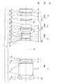
また、図1は、図2・図3に示すレンズユニット1を便宜上、一列状に展開した展開状態を示すレンズ構成図である。そして、図1に示すように、レンズユニット1は、変倍光学系11と撮像素子SRとを含むように構成されている。 FIG. 1 is a lens configuration diagram showing a developed state in which the
なお、この図1での「GRi」はレンズ群を示し、「Li」はレンズを示す。さらに、「si」は面(透過面等)を示している。そして、「GRi」・「Li」・「si」に付される数字(i)は、物体側から像側に至るまでの順番を示している。また、非球面の面には、「*」(アスタリスク)が付されている。そして、この図1に示される変倍光学系11(レンズユニット1)は実施例1とする。 In FIG. 1, “GRi” indicates a lens group, and “Li” indicates a lens. Further, “si” indicates a surface (transmission surface or the like). The numbers (i) given to “GRi”, “Li”, and “si” indicate the order from the object side to the image side. An aspheric surface is marked with “*” (asterisk). The variable magnification optical system 11 (lens unit 1) shown in FIG.
〈2−1.レンズユニットの構成について〉
レンズユニット1の変倍光学系11は、撮影対象(物体側)から順に、第1レンズ群GR1、第2レンズ群GR2、第3レンズ群GR3、および第4レンズ群GR4を有している。<2-1. Lens unit configuration>
The variable magnification
《2−1−1.第1レンズ群について》
第1レンズ群(物体側レンズ群、1番目のレンズ群)GR1は、第1レンズL1、光学プリズムPR、第2レンズL2、および第3レンズL3から構成されている。そして、この第1レンズ群GR1は、全体として「正」の光学的パワー(屈折力)を有している。なお、パワーは、焦点距離の逆数で定義されている。<< 2-1-1. About the first lens group >>
The first lens group (object side lens group, first lens group) GR1 includes a first lens L1, an optical prism PR, a second lens L2, and a third lens L3. The first lens group GR1 as a whole has a “positive” optical power (refractive power). The power is defined as the reciprocal of the focal length.
第1レンズ(前玉レンズ)L1は、物体側に凸の負メニスカスレンズである。 The first lens (front lens) L1 is a negative meniscus lens convex on the object side.
光学プリズム(光軸変更部材)PRは、物体側からの光線を直角に折り曲げることのできるプリズムである(例えば直角プリズムである)。なお、光学プリズムPRにおけるs3は光線の入射面、s4は光線の射出面になっている。 The optical prism (optical axis changing member) PR is a prism that can bend a light beam from the object side at a right angle (for example, a right angle prism). In the optical prism PR, s3 is a light incident surface, and s4 is a light exit surface.
第2レンズL2は、両側凸の正レンズ(両凸レンズ)である。第3レンズL3は、物体側に凸の正メニスカスレンズである。 The second lens L2 is a biconvex positive lens (biconvex lens). The third lens L3 is a positive meniscus lens convex toward the object side.
《2−1−2.第2レンズ群について》
第2レンズ群(中間レンズ群、2番目のレンズ群)GR2は、第4レンズL4、第5レンズL5、および第6レンズL6から構成されている。そして、この第2レンズ群GR2は、全体として「負」の光学的パワーを有している。<< 2-1-2. About the second lens group >>
The second lens group (intermediate lens group, second lens group) GR2 includes a fourth lens L4, a fifth lens L5, and a sixth lens L6. The second lens group GR2 as a whole has “negative” optical power.
第4レンズL4は、物体側に凸の負メニスカスレンズである。なお、s10は非球面(非球面形状の屈折光学面、非球面と等価な屈折作用を有する面等)になっている。 The fourth lens L4 is a negative meniscus lens convex toward the object side. Note that s10 is an aspherical surface (aspherical refractive optical surface, a surface having a refractive action equivalent to an aspherical surface, etc.).
第5レンズL5は、両側凹の負レンズ(両凹レンズ)である。第6レンズL6は、両側凸の正レンズである。なお、第5レンズL5と第6レンズL6とは、s13・s14を接合することで接合レンズを構成している。また、接合方法として、例えば接着剤による接合が挙げられる(なお、後述の接合レンズの接合方法としても、同様に接着剤等の接合が挙げられる)。 The fifth lens L5 is a negative lens (biconcave lens) concave on both sides. The sixth lens L6 is a positive lens convex on both sides. The fifth lens L5 and the sixth lens L6 constitute a cemented lens by cementing s13 and s14. Further, as a bonding method, for example, bonding with an adhesive can be mentioned (in addition, bonding with an adhesive or the like can be similarly used as a bonding method for a bonded lens described later).
《2−1−3.第3レンズ群について》
第3レンズ群(中間レンズ群、3番目のレンズ群)GR3は、光学絞りST、第7レンズL7、第8レンズL8、反射ミラーMR、第9レンズL9、第10レンズL10、および第11レンズL11から構成されている。そして、この第3レンズ群GR3は、全体として「正」の光学的パワーを有している。<< 2-1-3. About the third lens group >>
The third lens group (intermediate lens group, third lens group) GR3 includes an optical aperture stop ST, a seventh lens L7, an eighth lens L8, a reflection mirror MR, a ninth lens L9, a tenth lens L10, and an eleventh lens. L11. The third lens group GR3 as a whole has “positive” optical power.
光学絞りSTは、開口径を可変できる絞りである。そして、この光学絞りSTは、第3レンズ群GR3と一体的に構成されている。なお、図1は、この光学絞りST自体を、便宜上、s15と表記している。 The optical diaphragm ST is a diaphragm whose aperture diameter can be varied. The optical aperture stop ST is formed integrally with the third lens group GR3. In FIG. 1, the optical aperture stop ST itself is represented as s15 for convenience.
また、この光学絞りSTの配設箇所に、シャッターが設けられていてもよい。このような構成であれば、光学絞りSTやシャッターを移動させるための駆動源や移動機構が不要となり、レンズユニット1がコンパクトになるためである(なお、このようにシャッターは、下記の光学絞りSTにおいて設けられていてもよい)。 Further, a shutter may be provided at a location where the optical aperture stop ST is disposed. With such a configuration, the driving source and the moving mechanism for moving the optical aperture stop ST and the shutter become unnecessary, and the
第7レンズL7は、両側凸の正レンズである。なお、s16は非球面になっている。 The seventh lens L7 is a positive lens convex on both sides. Note that s16 is an aspheric surface.
第8レンズL8は、物体側に凹の負メニスカスレンズである。なお、第7レンズL7と第8レンズL8とは、s17・s18を接合することで接合レンズを構成している。 The eighth lens L8 is a negative meniscus lens concave on the object side. The seventh lens L7 and the eighth lens L8 constitute a cemented lens by cementing s17 and s18.
反射ミラー(光軸変更部材)MRは、第8レンズL8から射出してきた光線を反射させることで、第9レンズL9へと導くものである。なお、この反射ミラーMRは、第8レンズL8と第9レンズL9との間に位置するようになっている。 The reflection mirror (optical axis changing member) MR reflects the light beam emitted from the eighth lens L8 and guides it to the ninth lens L9. The reflection mirror MR is positioned between the eighth lens L8 and the ninth lens L9.
第9レンズL9は、両側凸の正レンズである。第10レンズL10は、両側凹の負レンズである。第11レンズL11は、物体側に凸の正メニスカスレンズである。なお、s27は非球面になっている。 The ninth lens L9 is a positive lens convex on both sides. The tenth lens L10 is a negative lens that is concave on both sides. The eleventh lens L11 is a positive meniscus lens convex toward the object side. Note that s27 is an aspheric surface.
《2−1−4.第4レンズ群について》
第4レンズ群(像側レンズ群、4番目のレンズ群)GR4は、第12レンズL12、ローパスフィルターLF、およびカバーガラスCGから構成されている。そして、この第4レンズ群GR4は、全体として「正」の光学的パワーを有している。<< 2-1-4. About the 4th lens group >>
The fourth lens group (image side lens group, fourth lens group) GR4 includes a twelfth lens L12, a low pass filter LF, and a cover glass CG. The fourth lens group GR4 as a whole has a “positive” optical power.
第12レンズL12は、両側凸の正レンズである。なお、s28・s29は非球面になっている。 The twelfth lens L12 is a positive lens convex on both sides. Note that s28 and s29 are aspherical surfaces.
ローパスフィルターLFは、2面(s30・s31)構成のフィルターであり、撮像素子SRの画素ピッチにより決定される所定の遮断周波数特性を有する光学的フィルター(例えば赤外線カットフィルター)である。 The low-pass filter LF is a filter having a two-surface (s30 / s31) configuration, and is an optical filter (for example, an infrared cut filter) having a predetermined cutoff frequency characteristic determined by the pixel pitch of the image sensor SR.
カバーガラスCGは、撮像素子SRの受光面を保護する2面(s32・s33)構成のガラスである。したがって、カバーガラスCGのs33と撮像素子SRの受光面とは、極めて近づくように配設されている(例えば、s33と受光面との間隔が0.5mm程度)。 The cover glass CG is a glass having a two-surface (s32 / s33) configuration that protects the light-receiving surface of the imaging element SR. Therefore, s33 of the cover glass CG and the light receiving surface of the imaging element SR are disposed so as to be very close (for example, the interval between s33 and the light receiving surface is about 0.5 mm).
《2−1−5.撮像素子について》
なお、本発明のレンズユニット1における撮像素子SRは可動になっている。例えば、駆動モータ(撮像素子用駆動モータ)と、その駆動力を撮像素子SRに伝達する伝達機構(撮像素子用伝達機構)とを含む撮像素子駆動部(不図示)が、撮像素子SRを移動させる。<< 2-1-5. About image sensor >>
Note that the image sensor SR in the
ただし、撮像素子SRの移動源は、この撮像素子駆動部の駆動力のみに限定されるものではない。例えば、撮像素子SRと第4レンズ群GR4とが連係(連結)して、光学系駆動部13の駆動力で、同時に(一体で)移動してもよい。このような構成であれば、例えば、撮像素子SR専用の移動用駆動源や、第4レンズ群GR4専用の移動用駆動源が不要になる。また、撮像素子SRと第4レンズ群GR4とが密着して一体化していれば、両者(撮像素子SR・第4レンズ群GR4)の間隔が比較的に狭くなる。したがって、レンズユニット1がコンパクトになる。 However, the movement source of the image sensor SR is not limited to the driving force of the image sensor drive unit. For example, the imaging element SR and the fourth lens group GR4 may be linked (connected) and moved simultaneously (integrally) by the driving force of the optical system driving unit 13. With such a configuration, for example, a moving drive source dedicated to the image sensor SR and a moving drive source dedicated to the fourth lens group GR4 are not required. Further, if the image sensor SR and the fourth lens group GR4 are in close contact with each other, the distance between them (the image sensor SR and the fourth lens group GR4) is relatively narrow. Therefore, the
したがって、実施の形態1や、後述する実施の形態2・3では、撮像素子SRと第4レンズ群GR4とが一体的に移動するレンズユニット1を例に挙げている。なお、撮像素子SRのハウジングと第4レンズ群GR4とが接着等されることで、撮像素子SRと第4レンズ群GR4との連係(一体化)は実現できる。なお、撮像素子SRと第4レンズ群GR4とが独立しているものの、一体で(同時に)移動するようになっていてもよい。 Therefore, in
〈2−2.変倍光学系(実施例1)のコンストラクションデータについて〉
次に、上記してきたレンズユニット1に含まれる実施例1の変倍光学系11のコンストラクションデータについて、表1・表2を用いて説明する。<2-2. Construction data of variable magnification optical system (Example 1)>
Next, construction data of the variable magnification

この表1での「ri」は、各面(si)における曲率半径[単位;mm]を示している。なお、非球面の面には、アスタリスク(*)が付されている。「di」は、i番目の面(si)と、i+1番目の面(si+1)との間における軸上面間隔[単位;mm]を示している。なお、ズーミングにより軸上面間隔が変化(変動)する場合、広角端状態(W)でのdi・中間焦点距離状態(M)でのdi・望遠端状態(T)でのdiが、この順で表記されている。 “Ri” in Table 1 indicates a radius of curvature [unit: mm] on each surface (si). An aspheric surface is marked with an asterisk (*). “Di” represents an axial upper surface distance [unit: mm] between the i-th surface (si) and the i + 1-th surface (si + 1). In addition, when the axial top surface distance changes (fluctuates) due to zooming, di in the wide-angle end state (W), di in the intermediate focal length state (M), di in the telephoto end state (T) are in this order. It is written.
また、「Ni」・「υi」は、軸上面間隔(di)での媒質の有する屈折率(Nd)・アッベ数(νd)を示している。なお、屈折率(Nd)・アッベ数(νd)は、d線(波長587.56nm)に対するものである。 “Ni” and “υi” indicate the refractive index (Nd) and the Abbe number (νd) of the medium at the axial upper surface spacing (di). The refractive index (Nd) and Abbe number (νd) are for the d-line (wavelength 587.56 nm).
また、「焦点距離状態」は、広角端状態(W;最短焦点距離状態)〜中間焦点距離状態(M)〜望遠端状態(T;最長焦点距離状態)を意味している。そして、「f」・「FNO」は、各焦点状態(W)・(M)・(T)に対応する全系の焦点距離[単位;mm]・Fナンバーを示している。 The “focal length state” means a wide angle end state (W: shortest focal length state) to an intermediate focal length state (M) to a telephoto end state (T: longest focal length state). “F” and “FNO” indicate the focal length [unit: mm] and the F number of the entire system corresponding to the respective focal states (W), (M), and (T).
ところで、上記の非球面は、下記の式(定義式1)で定義される。
X(H)=C0・H2/{1+√(1−ε・C02・H2)}+ΣAj・Hj…(定義式
1)
但し、定義式1中、
H;光軸AXに対しての垂直な方向の高さ、
X(H);高さHの位置での光軸AX方向(サグ)の変位量、
C0;近軸曲率(=1/ri)、
ε;2次曲面パラメータ、
j;非球面の次数、
Aj;j次の非球面係数、
である。By the way, the aspheric surface is defined by the following equation (definition equation 1).
X (H) = C0 · H2 / {1 + √ (1−ε · C02 · H2 )} + ΣAj · Hj (Definition Formula 1)
However, in
H: height in a direction perpendicular to the optical axis AX,
X (H): displacement in the optical axis AX direction (sag) at the position of height H,
C0 ; paraxial curvature (= 1 / ri),
ε; quadric surface parameter,
j: Degree of aspheric surface,
Aj: j-order aspheric coefficient,
It is.
そこで、非球面に関するデータ(非球面データ)を下記の表2に示す。ただし、表記されていない項の係数は「0」(ゼロ)であり、すべてのデータに関して、「E−n」=「×10-n」になっている。Therefore, data relating to the aspheric surface (aspherical surface data) is shown in Table 2 below. However, the coefficient of the term which is not described is “0” (zero), and “E−n” = “× 10−n ” for all data.
〈2−3.レンズユニットにおける各レンズ群の移動について〉
《2−3−1.ズーミングについて》
ここで、各レンズ群(GR1〜GR4)の移動について、図1を用いて説明する。レンズユニット1における変倍(ズーミング等)は、各レンズ群の間隔を光軸AXに沿って変化させることで行われる。例えば図1のレンズユニット1は、ズーミングの場合、各レンズ群における一部のレンズ群(第2レンズ群GR2等)を移動させている。<2-3. Movement of each lens group in the lens unit>
<< 2-3-1. About Zooming >>
Here, the movement of each lens group (GR1 to GR4) will be described with reference to FIG. Zooming (zooming, etc.) in the
なお、便宜上、図1は、ズーミングに伴う間隔変動の生じる軸上面間隔(di)のみに番号を付している。具体的には、d8・d14・d27が図示されている。 For convenience, in FIG. 1, only the shaft upper surface distance (di) in which the distance variation caused by zooming occurs is numbered. Specifically, d8, d14, and d27 are illustrated.
この図1のレンズ構成図は、広角端状態(W)でのレンズ配置を光学断面で示している。そして、図における矢印「MMi」は、望遠端状態(W)から中間焦点状態(M)、さらには、中間焦点状態(M)から望遠端状態(T)に至るまでの各レンズ群の移動を模式的に表記している。なお、MMiのiは物体側から像側に至るまでの順番を示している。したがって、各レンズ群の順番に対応する。 The lens configuration diagram of FIG. 1 shows the lens arrangement in the wide-angle end state (W) in an optical cross section. An arrow “MMi” in the figure indicates the movement of each lens group from the telephoto end state (W) to the intermediate focus state (M), and further from the intermediate focus state (M) to the telephoto end state (T). This is shown schematically. Note that i of MMi indicates the order from the object side to the image side. Therefore, it corresponds to the order of each lens group.
図1のレンズユニット1では、広角端状態(W)から望遠端状態(T)へのズーミングが行われる場合、第1レンズ群GR1と第2レンズ群GR2との間隔は増大、第2レンズ群GR2と第3レンズ群GR3との間隔は減少、第3レンズ群GR3と第4レンズ群GR4(撮像素子SRと一体構造の第4レンズ群GR4;以下、「GR4+SR」表記する場合あり)との間隔は増大する。 In the
具体的には、レンズユニット1は、第2レンズ群GR2を像側に移動させ、第4レンズ群GR4(GR4+SR)を像側へ移動させている。一方、レンズユニット1は、第1レンズ群GR1および第3レンズ群GR3を不動(位置固定)にして、ズーミングを行っている。 Specifically, the
このような各レンズ群〔GR1〜GR4(GR4+SR)〕におけるズーミングの移動量を示した表3を下記に示す。 Table 3 showing the amount of zooming movement in each of the lens groups [GR1 to GR4 (GR4 + SR)] is shown below.
なお、この表では、広角端状態(W)が基準になっている。そのため、広角端状態(W)の移動量[単位;mm]が、「0.0000」になっている。そして、この基準〔広角端状態(W)〕からの移動方向が、物体側から像側の場合「+」と表記し、像側から物体側の場合「−」と表記する。また、この表でのTL[単位;mm]は、第1レンズL1におけるr1の面頂点から撮像素子SRの受光面までの距離を表している。 In this table, the wide-angle end state (W) is a reference. Therefore, the movement amount [unit: mm] in the wide-angle end state (W) is “0.0000”. The movement direction from the reference [wide-angle end state (W)] is expressed as “+” when the object side is the image side, and is expressed as “−” when the image side is the object side. Further, TL [unit: mm] in this table represents the distance from the surface vertex of r1 in the first lens L1 to the light receiving surface of the image sensor SR.
この表3および図1からわかるように、実施例1の変倍光学系11を備えたレンズユニット1において、可動なレンズ群は、第2レンズ群GR2・第4レンズ群GR4(GR4+SR)になっている。そして、第2レンズ群GR2が、焦点距離を変えるためのバリエータとして機能し、第4レンズ群GR4(GR4+SR)が、ズーミングによって生じた像点移動を補正するコンペンセータとして機能している。 As can be seen from Table 3 and FIG. 1, in the
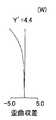
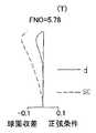
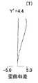
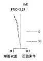
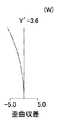
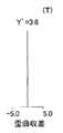
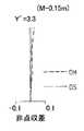
なお、図4〜図6は、ズーミングにおける変倍光学系11の収差を示している。具体的には、図4(図4A〜図4C)は広角端状態(W)での収差、図5(図5A〜図5C)は中間焦点距離状態(M)での収差、図6(図6A〜図6C)は望遠端状態(T)での収差を示している。 4 to 6 show aberrations of the variable magnification
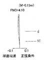
そして、図4A・図5A・図6Aは球面収差(spherical aberration;S.A.)・正弦条件(sine condition;S.C.)を示している。そして、図における線dはd線に対する球面収差[単位;mm]、破線SCは正弦条件不満足量[単位;mm]を示している。なお、これらの図には、FNO(Fナンバー)も表記されている。 4A, FIG. 5A, and FIG. 6A show spherical aberration (SA) and sine condition (SC). The line d in the figure indicates the spherical aberration [unit; mm] with respect to the d line, and the broken line SC indicates the unsatisfactory sine condition [unit; mm]. In these figures, FNO (F number) is also indicated.
図4B・図5B・図6Bは非点収差(astigmatism)を示している。そして、図における破線DMは、メリジオナル面でのd線に対する非点収差[単位;mm]を示している。また、線DSは、サジタル面でのd線に対する非点収差[単位;mm]を示している。なお、これらの図には、撮像素子SRの受光面上での最大像高(光軸AXからの距離)である「Y’」[単位;mm]も表記されている。 4B, FIG. 5B, and FIG. 6B show astigmatism. A broken line DM in the figure indicates astigmatism [unit: mm] with respect to the d-line on the meridional surface. A line DS indicates astigmatism [unit: mm] with respect to the d line on the sagittal surface. In these drawings, “Y ′” [unit: mm] which is the maximum image height (distance from the optical axis AX) on the light receiving surface of the image sensor SR is also described.
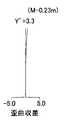
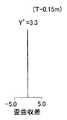
図4C・図5C・図6Cは歪曲収差(distortion)を示している。そして、図における実線は、d線に対する歪曲[単位;%]を示している。なお、これらの図にも、「Y’」が表記されている。 4C, FIG. 5C, and FIG. 6C show distortion. The solid line in the figure indicates the distortion [unit:%] with respect to the d line. In these figures, “Y ′” is also written.
《2−3−2.フォーカシングについて》
続いて、レンズユニット1における合焦(フォーカシング)について、下記の表4を用いて説明する。この表4は、上記のようにズーミングされた後、レンズユニット1で撮影対象(被写体)を撮影する場合(最短撮影距離の被写体を撮影する場合)のレンズ群の移動量を示している。<< 2-3-2. About Focusing >>
Subsequently, focusing in the
なお、この表4では、表3での各焦点距離状態〔(W)・(M)・(T)〕でのレンズ群の位置関係が基準になっている。また、表4での最短撮影距離[単位;mm]は、被写体の面(被写体面)から第1レンズL1におけるr1の面頂点までの距離になっている。 In Table 4, the positional relationship of the lens groups in each focal length state [(W), (M), (T)] in Table 3 is used as a reference. Further, the shortest shooting distance [unit: mm] in Table 4 is the distance from the surface of the subject (subject surface) to the surface vertex of r1 in the first lens L1.
この表4に示すように、いずれの焦点距離状態でのフォーカシングの場合、図1のレンズユニット1では、第4レンズ群GR4(GR4+SR)が像側へと移動する一方、第1レンズ群GR1〜第3レンズ群GR3は不動になっている。 As shown in Table 4, in the case of focusing at any focal length state, in the
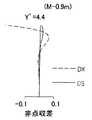
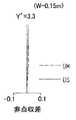
なお、図7〜図9は、フォーカシングにおける変倍光学系11の収差を示している。具体的には、図7(図7A〜図7C)は広角端状態(W)で最短撮影距離0.2[m]の場合の収差、図8(図8A〜図8C)は中間焦点距離状態(M)で最短撮影距離0.9[m]の場合の収差、図9(図9A〜図9C)は望遠端状態(T)で最短撮影距離0.9[m]の場合の収差を示している。また、図7A・図8A・図9Aは球面収差図、図7B・図8B・図9Bは非点収差図、図7C・図8C・図9Cは歪曲収差図になっている。そのため、各線の説明は、上記の図4〜図6を参照するものとする。 7 to 9 show aberrations of the variable magnification
〔3.本発明の種々の特徴の一例について〕
以上のように、本発明のレンズユニット1(実施例1の変倍光学系11を備えたレンズユニット1)は、第1レンズ群GR1〜第4レンズ群GR4を含む複数のレンズ群から成る変倍光学系11を備えるとともに、この変倍光学系11を経た撮像対象からの光を受光する撮像素子SRを備えている。[3. Example of various features of the present invention]
As described above, the
さらに、複数のレンズ群(GR1〜GR4)において、物体側に最も近いレンズ群である第1レンズ群GR1は、光軸を変更させる光学プリズムPRを含んでいる。そして、このような本発明のレンズユニット1では、ズーミングの場合、第1レンズ群GR1が不動である一方、撮像素子SRは光軸AXに沿って移動するようになっている。 Furthermore, in the plurality of lens groups (GR1 to GR4), the first lens group GR1, which is the lens group closest to the object side, includes an optical prism PR that changes the optical axis. In such a
一般的に、撮像素子SRが不動(固定状態)である一方、この撮像素子SRよりも撮像対象(物体側)に近いレンズ群(例えば第1レンズ群GR1)が可動である場合、撮像素子SRと第1レンズ群GR1との間隔が長いほど(すなわちレンズユニット1の全長が長いほど)、第1レンズ群GR1を構成するレンズの径(例えば第1レンズL1の径;前玉レンズ径)は大きくなる傾向がある。なぜなら、その第1レンズL1が、撮影対象に近づくために、比較的広い画角の光を受光する必要があるためである。したがって、この傾向は、広角撮影(広角端状態)の場合に顕著に現れる。 In general, when the imaging element SR is stationary (fixed state), and the lens group (for example, the first lens group GR1) closer to the imaging target (object side) than the imaging element SR is movable, the imaging element SR The longer the distance between the first lens group GR1 (that is, the longer the total length of the lens unit 1), the larger the diameter of the lenses constituting the first lens group GR1 (for example, the diameter of the first lens L1; the front lens diameter). There is a tendency to grow. This is because the first lens L1 needs to receive light having a relatively wide angle of view in order to approach the subject to be imaged. Therefore, this tendency is conspicuous in wide-angle shooting (wide-angle end state).
しかしながら、本発明のレンズユニットでは、ズーミングの場合、撮像素子SRが移動する(可動になっている)。一方、第1レンズ群GR1は、ズーミングの場合であっても、不動になっている。 However, in the lens unit of the present invention, the image sensor SR moves (becomes movable) during zooming. On the other hand, the first lens group GR1 is stationary even in zooming.
このように撮像素子SRが移動する一方、第1レンズ群GR1が不動なズーミングは、撮像素子SRが不動な一方、第1レンズ群GR1が可動するズーミングと同様な構成になる。なぜなら、撮像素子SRが不動な一方で第1レンズ群GR1が移動することと、撮像素子SRが移動する一方で第1レンズ群GR1が不動であることとは、相対的には、同義(等価)といえるためである。 The zooming in which the image pickup element SR moves while the first lens group GR1 does not move has the same configuration as the zooming in which the image pickup element SR does not move while the first lens group GR1 moves. This is because the movement of the first lens group GR1 while the imaging element SR is stationary and the movement of the imaging element SR while the first lens group GR1 is stationary are relatively synonymous (equivalent). This is because it can be said.
すると、本発明のレンズユニット1は、撮像素子SRを移動させることで、ズーミング(特に広角端撮影)できる。そのため、例えば第1レンズ群GR1が、撮影対象(物体側)に向かって繰り出す必要はなくなる。その結果、第1レンズ群GR1を構成する第1レンズL1等の径(例えば前玉径)が、比較的縮小する(コンパクトになる)。 Then, the
その上、不動なレンズ群である第1レンズ群GR1に、光学プリズムPRが設けられている。したがって、この光学プリズムPRも、比較的広い画角の光を受光する必要がなくなる。したがって、光学プリズムPRのサイズが、比較的縮小する。 In addition, an optical prism PR is provided in the first lens group GR1, which is an immovable lens group. Therefore, the optical prism PR does not need to receive light having a relatively wide angle of view. Therefore, the size of the optical prism PR is relatively reduced.
また、本発明のレンズユニット1では、第1レンズ群GR1と第4レンズ群GR4との間に位置する第2レンズ群GR2・第3レンズ群GR3における少なくとも1つのレンズ群(例えば第3レンズ群GR3)が、光軸を変更させる反射ミラーMRを含んでいる。 In the
そして、このような本発明のレンズユニット1では、ズーミングの場合、反射ミラーMRを含んだ第3レンズ群GR3が不動である一方、撮像素子SRが光軸AXに沿って移動するようになっているともいえる。 In such a
上記したように、本発明のレンズユニット1は、撮像素子SRを移動させることで、ズーミングする。そのため、第3レンズ群GR3が、撮影対象に向かって繰り出す必要は低くなる。その結果、比較的広い画角の光を受光する必要がなくなり、第3レンズ群GR3構成する第7レンズL7等の径が比較的縮小する。 As described above, the
その上、本発明のレンズユニット1では、第3レンズ群GR3に、反射ミラーMRが設けられている。したがって、この反射ミラーMRも、比較的広い画角の光を受光する必要がなくなる。したがって、反射ミラーMRのサイズが、比較的縮小する。 In addition, in the
なお、物体側から離れた第3レンズ群GR3の入射してくる光は、第1レンズ群GR1に入射してくる光に比べて低い像高の光(小さい光束径)になっていることがある。すると、この不動な第3レンズ群GR3に設けられた反射ミラーMRも、低い像高の光を受光するだけでよい。かかる場合、一層、反射ミラーMRのサイズが、比較的縮小する。 Note that the light incident on the third lens group GR3 away from the object side is light with a lower image height (small beam diameter) than the light incident on the first lens group GR1. is there. Then, the reflecting mirror MR provided in the stationary third lens group GR3 only needs to receive light with a low image height. In such a case, the size of the reflecting mirror MR is further reduced.
また、本発明のレンズユニット1は、上記の2つの特徴を兼ねそろえているともいえる。つまり、本発明のレンズユニット1は、第1レンズ群GR1は光学プリズムPRを含む一方、第3レンズ群GR3は反射ミラーMRを含んでいる。そして、ズーミングの場合、第1レンズ群GR1・第3レンズ群GR3は不動である一方、撮像素子SRは光軸に沿って移動するといえる。 In addition, it can be said that the
したがって、このようなレンズユニット1であれば、第1レンズ群GR1における第1レンズL1等のレンズ径、第3レンズ群GR3の第7レンズL7等のレンズ径、および両者(第1レンズ群GR1・第3レンズ群GR3)に設けられた各々の光軸変更部材(光学プリズムPR・反射ミラーMR)のサイズが縮小する。 Accordingly, in such a
また、図2・図3に示すように、レンズユニット1は、光学プリズムPRや反射ミラーMRを利用することで、光軸を変更させる(折り曲げる)ことができる。その上、これら光学プリズムPRや反射ミラーMRはコンパクト化になっている。また、変倍光学系11を構成するレンズの径も比較的コンパクトになっている。したがって、本発明のレンズユニット1を用いると、限られた空間内(スペース内)において、コンパクト化されたレンズ群を、比較的自由に配設させることができる。その結果、極めてコンパクトな撮像装置29が実現する。 As shown in FIGS. 2 and 3, the
ところで、通常、レンズユニット1がズーミングを行うと、上記したような、各種収差が発生する。この収差を補正するために、本発明のレンズユニット1は、撮像素子SRのみを動かすこともできる。しかし、撮像素子SRのみの移動だけでは、十分な補正を行うことは難しい。 By the way, normally, when the
そこで、本発明のレンズユニット1では、ズーミングの場合、撮像素子SRとともに、第4レンズ群GR4も移動する。つまり、本発明のレンズユニット1は、2つの可動体(第4レンズ群GR4等・撮像素子SR)で、収差を補正できる。したがって、撮像素子SRのみによる収差補正に比べて、十分な収差補正ができる。 Therefore, in the
なお、収差補正の点から、第4レンズ群GR4は、非球面(s28・s29)を有するレンズを含んでいてもよい。このような構成であれば、レンズユニット1は、効果的に収差補正できる。 From the viewpoint of aberration correction, the fourth lens group GR4 may include a lens having an aspheric surface (s28 / s29). With such a configuration, the
また、本発明のレンズユニット1は、第4レンズ群GR4を移動させている。そのため、第4レンズ群GR4以外のレンズ群(第1レンズ群GR1〜第3レンズ群GR3)に起因する収差を、可動な第4レンズ群GR4で効果的に補正できる。すると、本発明のレンズユニット1では、第1レンズ群GR1〜第3レンズ群GR3の設計自由度(例えば曲率等の設計自由度)が高まる。 In the
したがって、本発明は、レンズの径(前玉径等)や光軸変更部材(反射部材)を比較的コンパクトにした上、十分な収差補正もできるレンズユニット1になっている。 Therefore, the present invention is a
また、本発明のレンズユニット1は、第4レンズ群GR4と撮像素子SRとを一体化しており、フォーカシングの場合、複数のレンズ群(GR1〜GR4)で、第4レンズ群GR4以外のレンズ群(GR1〜GR3)の少なくとも1つ(実施例1では第1レンズ群GR1〜第3レンズ群GR3)を不動にする一方、光軸AXに沿って第4レンズ群GR4および撮像素子SRを同時に(一体で)移動させる。 In the
一般的に、変倍光学系11において、ズーミングが行われ、さらにフォーカシングが行われようとする場合、複数のレンズ群(GR1〜GR4)のいずれかのレンズ群が移動する。そのため、種々の収差が発生しやすい。特に、近距離撮影(例えば、最短撮影距離での撮影)が行われる場合、比較的にフォーカシングに要するレンズ群の移動量が大きくなる。そのため、収差は顕著に現れやすい。 In general, when zooming is performed in the variable magnification
本発明のレンズユニット1では、フォーカシングの場合、撮像素子SRが移動する一方、第4レンズ群GR4以外のレンズ群(GR1〜GR3)における少なくとも1つのレンズ群(例えば第1レンズ群GR1)が不動になっている。 In the
このように撮像素子SRが移動する一方、第1レンズ群GR1が不動なフォーカシングは、撮像素子SRが不動な一方、第1レンズ群GR1が可動するフォーカシングと同様な構成になる。そのため、本発明のレンズユニット1は、撮像素子が可動なフォーカシングの場合と同程度で収差補正を行える。 In this way, the focusing in which the image pickup element SR moves while the first lens group GR1 does not move has the same configuration as the focusing in which the image pickup element SR does not move while the first lens group GR1 moves. Therefore, the
その上、撮像素子SRと第4レンズ群GR4との一体的移動を実現するために、本発明のレンズユニット1では、両者(撮像素子SR・第4レンズ群GR4)が、例えば一体化していてもよい。このような一体化構造であれば、上記したように、レンズユニット1がコンパクトになる。さらに、第4レンズ群GR4以外のレンズ群(GR1〜GR3)に起因する収差は、可動な第4レンズ群GR4によって効率的に補正される。すると、本発明のレンズユニット1では、第1レンズ群GR1〜第3レンズ群GR3の設計自由度が高まる。 In addition, in order to realize integral movement of the image sensor SR and the fourth lens group GR4, in the
また、上記したように、レンズ群の移動に起因する収差の発生が抑制されている。そのため、収差補正のための第4レンズ群GR4の設計が簡単になる。したがって、この第4レンズ群GR4の設計自由度も高まる。 Further, as described above, the occurrence of aberration due to the movement of the lens group is suppressed. This simplifies the design of the fourth lens group GR4 for aberration correction. Accordingly, the degree of freedom in designing the fourth lens group GR4 is also increased.
また、本発明のレンズユニット1では、複数のレンズ群(GR1〜GR4)は、少なくとも、物体側から順に、正のパワーを有する第1レンズ群GR1と、負のパワーを有する第2レンズ群GR2と、正のパワーを有する第3レンズ群GR3と、正のパワーを有する第4レンズ群GR4と、を含んでいる。 In the
そして、このようなレンズユニット1は、広角端状態(W)から望遠端状態(T)までのズーミングの場合、第1レンズ群GR1と第2レンズ群GR2との間隔を増大させ、第2レンズ群GR2と第3レンズ群GR3との間隔を減少させ、第3レンズ群GR3と第4レンズ群GR4との間隔を増加させている。 Then, in the case of zooming from the wide-angle end state (W) to the telephoto end state (T), such a
このようなレンズユニット1では、第1レンズ群GR1が正のパワーを有し、その次の第2レンズ群GR2が負のパワーを有している。すると、まず、撮像対象からの光は、第1レンズ群GR1によって収斂される。その後、この収斂された光は、第2レンズ群GR2によって発散される。 In such a
かかる場合、第1レンズ群GR1と第2レンズ群GR2との間隔が増大している。すると、第1レンズ群GR1の焦点距離が、変倍光学系11の焦点距離(全系の焦点距離)よりも短くなる。さらに、第2レンズ群GR2が、この第1レンズ群GR1を通過した光の結像する手前で、光の収斂性を抑制させる。したがって、結像点が後方へずれる。すると、予め規定されるレンズユニット1の全長において、焦点距離が比較的長くなる。したがって、本発明のレンズユニット1は、比較的高倍率(比較的高い変倍比)を有する。 In such a case, the distance between the first lens group GR1 and the second lens group GR2 is increased. Then, the focal length of the first lens group GR1 becomes shorter than the focal length of the variable magnification optical system 11 (the focal length of the entire system). Further, the second lens group GR2 suppresses the light convergence before the image of light passing through the first lens group GR1 is formed. Therefore, the imaging point is shifted backward. Then, the focal length becomes relatively long over the entire length of the
その上、本発明のレンズユニット1は、第1レンズ群GR1と第2レンズ群GR2との間隔を増大させ、第2レンズ群GR2と第3レンズ群GR3との間隔を減少させ、第3レンズ群GR3と第4レンズ群GR4との間隔を増加させている。このような間隔でのズーミングは、例えば第2レンズ群GR2と第4レンズ群GR4との移動でもよい。また、第1レンズ群GR1〜第4レンズ群GR4の移動でもよい。 In addition, the
すると、ズーミングのためのレンズ群(GR1〜GR4)の移動が種々想定できる。したがって、比較的少ないレンズ群(例えばGR2・GR4)に、ズーミングを負担(変倍負担)させてもよいし、比較的多くのレンズ群(例えばGR1・GR2・GR4)にズーミングを負担させてもよい。したがって、本発明は、レンズ群の移動の自由度を高めたレンズユニット1になる。 Then, various movements of the lens groups (GR1 to GR4) for zooming can be assumed. Therefore, a relatively small number of lens groups (for example, GR2 and GR4) may be burdened with zooming (variation burden), or a relatively large number of lens groups (for example, GR1, GR2, and GR4) may be burdened with zooming. Good. Therefore, the present invention provides the
[実施の形態2]
本発明の実施の形態2について説明する。なお、実施の形態1で用いた部材と同様の機能を有する部材については、同一の符号を付記し、その説明を省略する。[Embodiment 2]
A second embodiment of the present invention will be described. In addition, about the member which has the same function as the member used in
実施の形態1のレンズユニット1では、複数のレンズ群(GR1〜GR4)において、第1レンズ群GR1・第3レンズ群GR3が不動になっていた。そして、この第1レンズ群GR1・第3レンズ群GR3に、光学プリズムPR・反射ミラーMRが設けられていた。しかし、本発明での不動になるレンズ群は、2つである必要はないし、設けられる光軸変更部材も2つである必要はない。つまり、少なくとも1つのレンズ群が不動になっていてもよい。そこで、第1レンズ群GR1のみが不動になった変倍光学系11を備えたレンズユニット1について説明する。 In the
〔1.レンズユニットについて〕
以下に、ズーミングの場合、第2レンズ群GR2・第3レンズ群GR3・第4レンズ群GR4(GR4+SR)が可動になったレンズユニット1について図10を用いて説明していく。なお、この実施の形態2のレンズユニット1が有する変倍光学系11を実施例2とする。そして、この実施例2は、一列に並ぶような変倍光学系11になっている。[1. Lens unit)
Hereinafter, in the case of zooming, the
〈1−1.レンズユニットの構成について〉
レンズユニット1の変倍光学系11(実施例2)は、実施例1同様、撮影対象(物体側)から順に、第1レンズ群GR1、第2レンズ群GR2、第3レンズ群GR3、および第4レンズ群GR4を有している。<1-1. Lens unit configuration>
As in the first embodiment, the variable magnification optical system 11 (second embodiment) of the
《1−1−1.第1レンズ群について》
第1レンズ群(物体側レンズ群、1番目のレンズ群)GR1は、第1レンズL1、光学プリズムPR、および第2レンズL2から構成されている。そして、この第1レンズ群GR1は、全体として「正」の光学的パワーを有している。<< 1-1-1. About the first lens group >>
The first lens group (object side lens group, first lens group) GR1 includes a first lens L1, an optical prism PR, and a second lens L2. The first lens group GR1 as a whole has a “positive” optical power.
第1レンズ(前玉レンズ)L1は、物体側に凸の負メニスカスレンズレンズである。 The first lens (front lens) L1 is a negative meniscus lens lens convex on the object side.
光学プリズムPRは、物体側からの光線を直角に折り曲げることのできるプリズムである(例えば直角プリズムである)。なお、光学プリズムPRにおけるs3は光線の入射面、s4は光線の射出面になっている。 The optical prism PR is a prism that can bend a light beam from the object side at a right angle (for example, a right-angle prism). In the optical prism PR, s3 is a light incident surface, and s4 is a light exit surface.
第2レンズL2は、両側凸の正レンズである。 The second lens L2 is a positive lens convex on both sides.
《1−1−2.第2レンズ群について》
第2レンズ群(中間レンズ群、2番目のレンズ群)GR2は、第3レンズL3、および第4レンズL4から構成されている。そして、この第2レンズ群GR2は、全体として「負」の光学的パワーを有している。<< 1-1-2. About the second lens group >>
The second lens group (intermediate lens group, second lens group) GR2 includes a third lens L3 and a fourth lens L4. The second lens group GR2 as a whole has “negative” optical power.
第3レンズL3は、両側凹の負レンズである。なお、s7・s8は非球面になっている。第4レンズL4は、物体側に凸の正メニスカスレンズである。 The third lens L3 is a negative lens that is concave on both sides. Note that s7 and s8 are aspherical surfaces. The fourth lens L4 is a positive meniscus lens convex on the object side.
《1−1−3.第3レンズ群について》
第3レンズ群(中間レンズ群、3番目のレンズ群)GR3は、光学絞りST、第5レンズL5、第6レンズL6、第7レンズL7、および第8レンズL8から構成されている。そして、この第3レンズ群GR3は、全体として「正」の光学的パワーを有している。<< 1-1-3. About the third lens group >>
The third lens group (intermediate lens group, third lens group) GR3 includes an optical aperture stop ST, a fifth lens L5, a sixth lens L6, a seventh lens L7, and an eighth lens L8. The third lens group GR3 as a whole has “positive” optical power.
光学絞りSTは、上記同様、開口径を可変できる絞りである。そして、この光学絞りSTは、第3レンズ群GR3と一体的に構成されている。なお、図10は、この光学絞りST自体を、便宜上、s11と表記している。 The optical aperture stop ST is an aperture that can vary the aperture diameter as described above. The optical aperture stop ST is formed integrally with the third lens group GR3. In FIG. 10, the optical aperture stop ST itself is represented as s11 for convenience.
第5レンズL5は、物体側に凸の負メニスカスレンズである。第6レンズL6は、両側凸の正レンズである。第7レンズL7は、物体側に凸の正メニスカスレンズである。 The fifth lens L5 is a negative meniscus lens convex toward the object side. The sixth lens L6 is a positive lens convex on both sides. The seventh lens L7 is a positive meniscus lens convex on the object side.
第8レンズL8は、物体側に凸の負メニスカスレンズである。なお、s19は非球面になっている。また、第7レンズL7と第8レンズL8とは、s17・s18を接合することで接合レンズを構成している。 The eighth lens L8 is a negative meniscus lens convex toward the object side. Note that s19 is an aspherical surface. The seventh lens L7 and the eighth lens L8 constitute a cemented lens by cementing s17 and s18.
《1−1−4.第4レンズ群について》
第4レンズ群(像側レンズ群、4番目のレンズ群)GR4は、第9レンズL9、平行平面板PT、およびカバーガラスCGから構成されている。そして、この第4レンズ群GR4は、全体として「正」の光学的パワーを有している。<< 1-1-4. About the 4th lens group >>
The fourth lens group (image side lens group, fourth lens group) GR4 includes a ninth lens L9, a plane parallel plate PT, and a cover glass CG. The fourth lens group GR4 as a whole has a “positive” optical power.
第9レンズL9は、物体側に凸の正メニスカスレンズある。なお、s20・s21は非球面になっている。 The ninth lens L9 is a positive meniscus lens convex on the object side. Note that s20 and s21 are aspherical surfaces.
平行平面板PTは、2面(s22・s23)構成になっている。なお、この平行平面板PTは、ローパスフィルターとしての機能を有している。 The plane parallel plate PT has a two-surface (s22 / s23) configuration. The plane parallel plate PT functions as a low-pass filter.
カバーガラスCGは、撮像素子SRの受光面を保護する2面(s24・s25)構成のガラスである。したがって、カバーガラスCGのs25と撮像素子SRの受光面とは、極めて近づくように配設されている。 The cover glass CG is a glass with a two-surface (s24 / s25) configuration that protects the light-receiving surface of the image sensor SR. Therefore, s25 of the cover glass CG and the light receiving surface of the image sensor SR are disposed so as to be very close to each other.
〈1−2.変倍光学系(実施例2)のコンストラクションデータについて〉
次に、上記した実施例2の変倍光学系11のコンストラクションデータについて、表5・表6を用いて説明する。なお、この表5・表6は、上記の表1・表2と同様の表現になっている。<1-2. Construction data of variable magnification optical system (Example 2)>
Next, the construction data of the variable magnification
〈1−3.レンズユニットにおける各レンズ群の移動について〉
《1−3−1.ズーミングについて》
ここで、各レンズ群(GR1〜GR4)の移動について、図10を用いて説明する。なお、便宜上、図10は、ズーミングに伴う間隔変動の生じる軸上面間隔(di)のみに番号を付している。具体的には、d6・d10・d19が図示されている。<1-3. Movement of each lens group in the lens unit>
<< 1-3-1. About Zooming >>
Here, the movement of each lens group (GR1 to GR4) will be described with reference to FIG. For convenience, in FIG. 10, only the shaft upper surface distance (di) in which the distance variation caused by zooming occurs is numbered. Specifically, d6, d10, and d19 are illustrated.
広角端状態(W)から望遠端状態(T)へのズーミングが行われる場合、図10のレンズユニット1では、第1レンズ群GR1と第2レンズ群GR2との間隔は増大、第2レンズ群GR2と第3レンズ群GR3との間隔は減少、第3レンズ群GR3と第4レンズ群GR4(GR4+SR)との間隔は増大する。 When zooming from the wide-angle end state (W) to the telephoto end state (T) is performed, in the
具体的には、レンズユニット1は、第2レンズ群GR2・第4レンズ群GR4(GR4+SR)を像側に移動させ、第3レンズ群GR3を物体側へ移動させている。一方、レンズユニット1は、第1レンズ群GR1を不動(位置固定)にして、ズーミングを行っている。 Specifically, the
このような各レンズ群〔GR1〜GR4(GR4+SR)〕におけるズーミングの移動量を示した表7を下記に示す。なお、この表7は、上記の表3と同様の表現になっている。 Table 7 below shows the amount of zooming movement in each lens group [GR1 to GR4 (GR4 + SR)]. Table 7 has the same expression as Table 3 above.
この表7および図10からわかるように、実施例2の変倍光学系11を備えたレンズユニット1において、可動なレンズ群は、第2レンズ群GR2・第3レンズ群GR3・第4レンズ群GR4(GR4+SR)になっている。 As can be seen from Table 7 and FIG. 10, in the
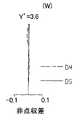
なお、図11〜図13は、ズーミングにおける変倍光学系11の収差を示している。そして、この図11〜図13は、図4〜図6と同様の表現になっている。 11 to 13 show aberrations of the variable magnification
《1−3−2.フォーカシングについて》
続いて、レンズユニット1におけるフォーカシングについて、下記の表8を用いて説明する。なお、この表8は、上記の表4と同様の表現になっている。<< 1-3-2. About Focusing >>
Subsequently, focusing in the
この表8に示すように、いずれの焦点距離状態でのフォーカシングの場合、図10のレンズユニット1では、第4レンズ群GR4(GR4+SR)が像側へと移動する一方、第1レンズ群GR1〜第3レンズ群GR3は不動になっている。 As shown in Table 8, in the case of focusing at any focal length state, in the
なお、図14〜図16は、フォーカシングにおける変倍光学系11の収差を示している。そして、この図14〜図16は、図7〜図9と同様の表現になっている。 14 to 16 show aberrations of the variable magnification
〔2.本発明の種々の特徴の一例について〕
以上のように、実施の形態2におけるレンズユニット1は、実施の形態1同様に、第1レンズ群GR1〜第4レンズ群GR4(複数のレンズ群)から成る変倍光学系11を備えるとともに、この変倍光学系11を経た撮像対象からの光を受光する撮像素子SRを備えている。[2. Example of various features of the present invention]
As described above, the
そして、複数のレンズ群(GR1〜GR4)において、物体側に最も近いレンズ群である第1レンズ群GR1は、光軸を変更させる光学プリズムPRを含んでいる。そして、このような本発明のレンズユニット1では、ズーミングの場合、第1レンズ群GR1は不動である一方、撮像素子SRは光軸AXに沿って移動するようになっている。 In the plurality of lens groups (GR1 to GR4), the first lens group GR1, which is the lens group closest to the object side, includes an optical prism PR that changes the optical axis. In such a
つまり、実施の形態2のレンズユニット1(図10参照)は、実施の形態1同様、第1レンズ群GR1が不動となっている点や、第4レンズ群GR4・撮像素子SRが移動する点、または光学的パワーの配置順は同一になっている点等、実施の形態1に類似したレンズユニット1になっている。 That is, in the
そのため、実施の形態2のレンズユニット1は、実施の形態1で説明した、下記の効果を少なくとも発揮する。 Therefore, the
・ズーミングの場合、撮像素子SRが移動することから、第1レンズ群GR1が、撮影対象に向かって繰り出す必要はなくなる。したがって、第1レンズ群GR1を構成する第1レンズL1等の径(例えば前玉径)や光学プリズムPRが、比較的縮小するという効果。
・ズーミングの場合、複数の可動体〔第2レンズ群GR2〜第4レンズ群GR4(GR4+SR)〕が、収差補正していることから、撮像素子SRのみによる収差補正に比べて、十分な収差補正が行える効果。
・ズーミングの場合、特に、第4レンズ群GR4(GR4+SR)が移動することで、第1レンズ群GR1〜第3レンズ群GR3に起因する収差を効率よく収差補正できることから、第1レンズ群GR1〜第3レンズ群GR3の設計自由度(例えば曲率等の設計自由度)が高まるという効果。
・第4レンズ群GR4と撮像素子SRとが一体化していることから、変倍光学系11、ひいてはレンズユニット1が比較的縮小するという効果。
・第4レンズ群GR4に含まれるレンズが、非球面(s20・s21)を有していることから、効率的な収差補正ができるという効果。
・フォーカシングの場合、撮像素子SRが移動することから、第1レンズ群GR1が、撮影対象(物体側)に向かって繰り出す必要はなくなる。したがって、レンズ群の移動に起因する収差の発生が抑制されるという効果。
・フォーカシングの場合、第4レンズ群GR4(GR4+SR)が移動することで、第1レンズ群GR1〜第3レンズ群GR3に起因する収差を効率よく収差補正できることから、第1レンズ群GR1〜第3レンズ群GR3の設計自由度(例えば曲率等の設計自由度)が高まるという効果。
・フォーカシングの場合、第1レンズ群GR1〜第3レンズ群GR3のレンズ群の移動に起因する収差の発生が抑制されることから、収差補正のための第4レンズ群GR4の設計が簡単になり、この第4レンズ群GR4の設計自由度が高まるという効果。
・変倍光学系1(実施例2)が、正・負・正・正のレンズ群配置を有していることから、この変倍光学系11、ひいてはレンズユニット1が高い変倍比を有するという効果。
・ズーミングの場合、第1レンズ群GR1と第2レンズ群GR2との間隔が増大し、第2レンズ群GR2と第3レンズ群GR3との間隔が減少し、第3レンズ群GR3と第4レンズ群GR4との間隔が増加していることから、レンズ群の移動の自由度の高まったレンズユニット1が実現するという効果。In zooming, since the image sensor SR moves, it is not necessary for the first lens group GR1 to extend toward the object to be imaged. Therefore, an effect that the diameter (for example, the front lens diameter) of the first lens L1 and the like constituting the first lens group GR1 and the optical prism PR are relatively reduced.
In the case of zooming, since a plurality of movable bodies [second lens group GR2 to fourth lens group GR4 (GR4 + SR)] correct aberrations, sufficient aberration correction compared to aberration correction using only the image sensor SR The effect that can be done.
In zooming, in particular, aberrations caused by the first lens group GR1 to the third lens group GR3 can be efficiently corrected by moving the fourth lens group GR4 (GR4 + SR). The effect that the design freedom (for example, design freedom, such as curvature) of 3rd lens group GR3 increases.
-Since the fourth lens group GR4 and the image pickup element SR are integrated, the variable magnification
-Since the lenses included in the fourth lens group GR4 have aspherical surfaces (s20 and s21), an effect that an efficient aberration correction can be performed.
In the case of focusing, since the image sensor SR moves, it is not necessary for the first lens group GR1 to extend toward the photographing target (object side). Therefore, the effect of suppressing the occurrence of aberration due to the movement of the lens group.
In the case of focusing, since the fourth lens group GR4 (GR4 + SR) is moved, aberrations caused by the first lens group GR1 to the third lens group GR3 can be efficiently corrected, so that the first lens group GR1 to the third lens group GR3. The effect that the degree of design freedom (for example, the degree of freedom of design such as curvature) of the lens group GR3 increases.
In the case of focusing, since the generation of aberration due to the movement of the lens groups of the first lens group GR1 to the third lens group GR3 is suppressed, the design of the fourth lens group GR4 for aberration correction is simplified. The effect that the design freedom of this 4th lens group GR4 increases.
Since the variable magnification optical system 1 (Example 2) has a positive / negative / positive / positive lens group arrangement, the variable magnification
In zooming, the distance between the first lens group GR1 and the second lens group GR2 increases, the distance between the second lens group GR2 and the third lens group GR3 decreases, and the third lens group GR3 and the fourth lens The effect that the
[実施の形態3]
本発明の実施の形態3について説明する。なお、実施の形態1・2で用いた部材と同様の機能を有する部材については、同一の符号を付記し、その説明を省略する。[Embodiment 3]
実施の形態1・2は、物体側から順に、正・負・正・正の順で並ぶレンズ群(GR1〜GR4)を備えたレンズユニット1を説明してきた。しかし、本発明は、このような配置に限定されるものではない。 In the first and second embodiments, the
〔1.レンズユニットについて〕
そこで、以下に、異なる配置のレンズユニット1について図17を用いて説明していく。なお、この実施の形態3のレンズユニット1が有する変倍光学系11を実施例3とする。そして、この実施例3は、一列に並ぶような変倍光学系11になっている。[1. Lens unit)
Therefore, the
〈1−1.レンズユニットの構成について〉
レンズユニット1の変倍光学系11(実施例3)は、実施例1・2同様、撮影対象(物体側)から順に、第1レンズ群GR1、第2レンズ群GR2、第3レンズ群GR3、および第4レンズ群GR4を有している。<1-1. Lens unit configuration>
The variable magnification optical system 11 (Example 3) of the
《1−1−1.第1レンズ群について》
第1レンズ群(物体側レンズ群、1番目のレンズ群)GR1は、第1レンズL1、光学プリズムPR、第2レンズL2、第3レンズL3から構成されている。そして、この第1レンズ群GR1は、全体として「負」の光学的パワーを有している。<< 1-1-1. About the first lens group >>
The first lens group (object side lens group, first lens group) GR1 includes a first lens L1, an optical prism PR, a second lens L2, and a third lens L3. The first lens group GR1 as a whole has “negative” optical power.
第1レンズ(前玉レンズ)L1は、物体側に凸の負メニスカスレンズレンズである。なお、s2は非球面になっている。 The first lens (front lens) L1 is a negative meniscus lens lens convex on the object side. Note that s2 is an aspheric surface.
光学プリズムPRは、物体側からの光線を直角に折り曲げることのできるプリズムである(例えば直角プリズムである)。なお、光学プリズムPRにおけるs3は光線の入射面、s4は光線の射出面になっている。 The optical prism PR is a prism that can bend a light beam from the object side at a right angle (for example, a right-angle prism). In the optical prism PR, s3 is a light incident surface, and s4 is a light exit surface.
第2レンズL2は、両側凹の負レンズである。第3レンズL3は、物体側に凸の正メニスカスレンズである。なお、第2レンズL2と第3レンズL3とは、s6・s7を接合することで接合レンズを構成している。 The second lens L2 is a negative lens that is concave on both sides. The third lens L3 is a positive meniscus lens convex toward the object side. The second lens L2 and the third lens L3 constitute a cemented lens by cementing s6 and s7.
《1−1−2.第2レンズ群について》
第2レンズ群(中間レンズ群、2番目のレンズ群)GR2は、光学絞りST、第4レンズL4、および第5レンズL5、第6レンズL6、および第7レンズL7から構成されている。そして、この第2レンズ群GR2は、全体として「正」の光学的パワーを有している。<< 1-1-2. About the second lens group >>
The second lens group (intermediate lens group, second lens group) GR2 includes an optical aperture stop ST, a fourth lens L4, a fifth lens L5, a sixth lens L6, and a seventh lens L7. The second lens group GR2 as a whole has a “positive” optical power.
光学絞りSTは、上記同様、開口径を可変できる絞りである。そして、この光学絞りSTは、第2レンズ群GR2と一体的に構成されている。なお、図17は、この光学絞りST自体を、便宜上、s9と表記している。 The optical aperture stop ST is an aperture that can vary the aperture diameter as described above. The optical aperture stop ST is formed integrally with the second lens group GR2. In FIG. 17, the optical aperture stop ST itself is denoted as s9 for convenience.
第4レンズL4は、物体側に凸の正メニスカスレンズである。第5レンズL5は、両側凸の正レンズである。 The fourth lens L4 is a positive meniscus lens convex on the object side. The fifth lens L5 is a positive lens convex on both sides.
第6レンズL6は、両側凹の負レンズである。なお、第5レンズL5と第6レンズL6とは、s13・s14を接合することで接合レンズを構成している。 The sixth lens L6 is a negative lens that is concave on both sides. The fifth lens L5 and the sixth lens L6 constitute a cemented lens by cementing s13 and s14.
第7レンズL7は、物体側に凹の正メニスカスレンズである。なお、s16・s17は非球面になっている。 The seventh lens L7 is a positive meniscus lens concave on the object side. Note that s16 and s17 are aspherical surfaces.
《1−1−3.第3レンズ群について》
第3レンズ群(中間レンズ群、3番目のレンズ群)GR3は、第8レンズL8、および第9レンズL9から構成されている。そして、この第3レンズ群GR3は、全体として「正」の光学的パワーを有している。<< 1-1-3. About the third lens group >>
The third lens group (intermediate lens group, third lens group) GR3 includes an eighth lens L8 and a ninth lens L9. The third lens group GR3 as a whole has “positive” optical power.
第8レンズL8は、両側凹の負レンズである。第9レンズL9は、両側凸の正レンズである。なお、s20・s21は非球面になっている。 The eighth lens L8 is a negative lens that is concave on both sides. The ninth lens L9 is a positive lens convex on both sides. Note that s20 and s21 are aspherical surfaces.
《1−1−4.第4レンズ群について》
第4レンズ群(像側レンズ群、4番目のレンズ群)GR4は、第10レンズL10、平行平面板PT、およびカバーガラスCGから構成されている。そして、この第4レンズ群GR4は、全体として「負」の光学的パワーを有している。<< 1-1-4. About the 4th lens group >>
The fourth lens group (image side lens group, fourth lens group) GR4 includes a tenth lens L10, a plane parallel plate PT, and a cover glass CG. The fourth lens group GR4 as a whole has a “negative” optical power.
第10レンズL10は、物体側に凸の負メニスカスレンズある。 The tenth lens L10 is a negative meniscus lens convex on the object side.
平行平面板PTは、2面(s24・s25)構成になっている。なお、この平行平面板PTは、ローパスフィルターとしての機能を有している。 The plane parallel plate PT has a two-surface (s24 / s25) configuration. The plane parallel plate PT functions as a low-pass filter.
カバーガラスCGは、撮像素子SRの受光面を保護する2面(s26・s27)構成のガラスである。したがって、カバーガラスCGのs27と撮像素子SRの受光面とは、極めて近づくように配設されている。 The cover glass CG is a glass having a two-surface (s26 / s27) configuration that protects the light-receiving surface of the image sensor SR. Therefore, s27 of the cover glass CG and the light receiving surface of the imaging element SR are disposed so as to be very close to each other.
〈1−2.変倍光学系(実施例3)のコンストラクションデータについて〕
次に、上記して実施例3の変倍光学系11のコンストラクションデータについて、表9・表10を用いて説明する。なお、この表9・表10は、上記の表1・表2と同様の表現になっている。<1-2. About construction data of variable magnification optical system (Example 3)]
Next, the construction data of the variable magnification
〈1−3.レンズユニットにおける各レンズ群の移動について〉
《1−3−1.ズーミングについて》
ここで、各レンズ群(GR1〜GR4)の移動について、図17を用いて説明する。なお、便宜上、図17は、ズーミングに伴う間隔変動の生じる軸上面間隔(di)のみに番号を付している。具体的には、d8・d17・d21が図示されている。<1-3. Movement of each lens group in the lens unit>
<< 1-3-1. About Zooming >>
Here, the movement of each lens group (GR1 to GR4) will be described with reference to FIG. For convenience, in FIG. 17, only the shaft upper surface distance (di) in which the distance variation accompanying zooming occurs is numbered. Specifically, d8, d17, and d21 are illustrated.
すると、広角端状態(W)から望遠端状態(T)へのズーミングが行われる場合、レンズユニット1では、第1レンズ群GR1と第2レンズ群GR2との間隔は減少、第2レンズ群GR2と第3レンズ群GR3との間隔は増大、第3レンズ群GR3と第4レンズ群GR4(GR4+SR)との間隔は減少する。 Then, when zooming from the wide-angle end state (W) to the telephoto end state (T) is performed, in the
具体的には、レンズユニット1は、第2レンズ群GR2を物体側へ移動させるともに、第3レンズ群GR3・第4レンズ群GR4(GR4+SR)を像側へUターン移動させる一方、第1レンズ群GR1を不動(位置固定)にして、ズーミングを行っている。 Specifically, the
このような各レンズ群〔GR1〜GR4(GR4+SR)〕ズーミングの移動量を示した表11を下記に示す。なお、この表11は、上記の表3と同様の表現になっている。 Table 11 below shows the amount of movement of each lens group [GR1 to GR4 (GR4 + SR)] zooming. This Table 11 is expressed in the same manner as Table 3 above.
この表11および図17からわかるように、実施例3の変倍光学系11を備えたレンズユニット1において、可動な群は、第2レンズ群GR2・第3レンズ群GR3・第4レンズ群GR4(GR4+SR)になっている。 As can be seen from Table 11 and FIG. 17, in the
なお、図18〜図20は、ズーミングにおける変倍光学系11の収差を示している。そして、この図18〜図20は、図4〜図6と同様の表現になっている。 18 to 20 show aberrations of the variable magnification
《1−3−2.フォーカシングについて》
続いて、レンズユニット1におけるフォーカシングについて、下記の表12を用いて説明する。なお、この表12は、上記の表4と同様の表現になっている。<< 1-3-2. About Focusing >>
Next, focusing in the
この表12に示すように、広角端状態(W)・望遠端状態(T)でのフォーカシングの場合、図17のレンズユニット1では、第3レンズ群GR3・第4レンズ群GR4(GR4+SR)が像側に移動する一方、第1レンズ群GR1・第2レンズ群GR2は不動になっている。 As shown in Table 12, in the case of focusing in the wide-angle end state (W) / telephoto end state (T), in the
また、中間焦点距離状態(M)でのフォーカシングの場合、このレンズユニット1では、第2レンズ群GR2が物体側へ移動するとともに、第3レンズ群GR3・第4レンズ群GR4(GR4+SR)が像側へ移動する。一方、第1レンズ群GR1は、不動になっている。 In the case of focusing in the intermediate focal length state (M), in the
なお、図21〜図23は、フォーカシングにおける変倍光学系11の収差を示している。そして、この図21〜図23は、図7〜図9と同様の表現になっている。 21 to 23 show aberrations of the variable magnification
〔2.本発明の種々の特徴の一例について〕
以上のように、本発明のレンズユニット1では、複数のレンズ群は、少なくとも、物体側から順に、負のパワーを有する第1レンズ群GR1、正のパワーを有する第2レンズ群GR2、正のパワーを有する第3レンズ群GR3、を含んでいるといえる。[2. Example of various features of the present invention]
As described above, in the
そして、このようなレンズユニット1は、広角端状態(W)から望遠端状態(T)までのズーミングの場合、第1レンズ群GR1と第2レンズ群GR2との間隔を減少させ、第2レンズ群GR2と第3レンズ群GR3との間隔を増大させている。 Such a
このようなレンズユニットでは、第1レンズ群GR1が負のパワーを有し、その次の第2レンズ群GR2が正のパワーを有している。すると、まず、撮像対象からの光は、第1レンズ群GR1によって発散される。その後、この発散された光は、第2レンズ群GR2によって収斂される。 In such a lens unit, the first lens group GR1 has a negative power, and the second lens group GR2 after that has a positive power. Then, first, light from the imaging target is diverged by the first lens group GR1. Thereafter, the diverged light is converged by the second lens group GR2.
かかる場合、第1レンズ群GR1と第2レンズ群GR2との間隔が減少している。すると、レンズユニット1では、変倍光学系11の主点(後側主点)が第2レンズ群GR2よりも後方に位置する。そのため、予め規定されるレンズユニット1の全長において、焦点距離が比較的短くなる。したがって、本発明は、広い画角の光を受光できる広角化されたレンズユニット1になる。 In such a case, the distance between the first lens group GR1 and the second lens group GR2 is reduced. Then, in the
その上、本発明のレンズユニット1は、第1レンズ群GR1と第2レンズ群GR2との間隔を減少させ、第2レンズ群GR2と第3レンズ群GR3との間隔を増大させている。このような間隔でのズーミングは、1つのレンズ群(例えば第2レンズ群GR2)の移動でも、複数のレンズ群(例えばGR1〜GR3)の移動でも実現できる。 In addition, the
すると、ズーミングのためのレンズ群(例えばGR1〜GR3)の移動が種々想定できる。したがって、比較的少ないレンズ群(例えばGR2)に、ズーミングを負担(変倍負担)させてもよいし、比較的多くのレンズ群(例えばGR1〜GR3)にズーミングを負担させてもよい。したがって、本発明は、レンズ群の移動の自由度を高めたレンズユニット1になる。 Then, various movements of the lens group (for example, GR1 to GR3) for zooming can be assumed. Therefore, zooming may be burdened (zooming burden) on a relatively small number of lens groups (for example, GR2), or zooming may be burdened on a relatively large number of lens groups (for example, GR1 to GR3). Therefore, the present invention provides the
なお、図示してはいないが、本発明のレンズユニット1は、第1レンズ群GR1と第2レンズ群GR2との間隔を減少させ、第2レンズ群GR2と第3レンズ群GR3との間隔を減少させていてもよい。 Although not shown, the
なぜなら、第1レンズ群GR1と第2レンズ群GR2との間隔が減少しているため、レンズユニット1が、広い画角の光を受光できるためである。すなわち、本発明は、第1レンズ群GR1と第2レンズ群GR2との間隔を減少させ、第2レンズ群GR2と第3レンズ群GR3との間隔を減少させるズーミングであっても、上記同様、広角化された上に、レンズ群の移動の自由度を高めたレンズユニット1になる。 This is because the distance between the first lens group GR1 and the second lens group GR2 is reduced, so that the
また、本発明のレンズユニット1では、複数のレンズ群は、上記の正のパワーを有する第3レンズ群GR3の次に、負のパワーを有する第4レンズ群GR4を含んでいるともいえる。 Further, in the
そして、このようなレンズユニット1は、広角端状態(W)から望遠端状態(T)までのズーミングの場合、第1レンズ群GR1と第2レンズ群GR2との間隔を減少させ、第2レンズ群GR2と第3レンズ群GR3との間隔を増大させ、第3レンズ群GR3と第4レンズ群GR4との間隔を減少させている。 Such a
通常、シェーディングの発生を抑制する観点から、撮像素子SRに入射する光は、撮像素子SRの受光面に対して垂直であることが好ましい(受光面に対するテレセントリック性の高い方が好ましい)。そこで、本発明は、正のパワーを有する第3レンズ群GR3の次に、負のパワーを有する第4レンズ群GR4を配置する。かかる場合、正のパワーを有する第3レンズ群GR3を通過して収斂した光は、負のパワーを有する第4レンズ群GR4を通過する。 Usually, from the viewpoint of suppressing the occurrence of shading, the light incident on the image sensor SR is preferably perpendicular to the light receiving surface of the image sensor SR (higher telecentricity with respect to the light receiving surface is preferable). Therefore, in the present invention, the fourth lens group GR4 having negative power is arranged after the third lens group GR3 having positive power. In this case, the light converged through the third lens group GR3 having positive power passes through the fourth lens group GR4 having negative power.
すると、第4レンズ群GR4を通過することで発散した光は、撮像素子SRの受光面に対してゼロの入射角(≒0°)になりうる。つまり、受光面に対してほぼ垂直で、光が入射する。そのため、第4レンズ群GR4を通過した光(発散光)は、第3レンズ群GR3を通過した直後の光(収斂光)よりも、撮像素子SRの受光面に対して、高いテレセントリック性を発揮するといえる。その結果、本発明は、広角化されながらも、シューディングの抑制されたレンズユニット1になる。 Then, the light diverged by passing through the fourth lens group GR4 can have a zero incident angle (≈0 °) with respect to the light receiving surface of the image sensor SR. That is, light is incident substantially perpendicular to the light receiving surface. Therefore, the light (divergent light) that has passed through the fourth lens group GR4 exhibits higher telecentricity on the light receiving surface of the image sensor SR than the light (converged light) that has just passed through the third lens group GR3. That's right. As a result, the present invention provides a
なお、実施の形態3におけるレンズユニット1は、実施の形態1・2同様に、複数のレンズ群(GR1〜GR4)から成る変倍光学系11を備えるとともに、この変倍光学系11を経た撮像対象からの光を受光する撮像素子SRを備えている。 The
そして、複数のレンズ群(GR1〜GR4)において、物体側に最も近いレンズ群である第1レンズ群GR1は、光軸を変更させる光学プリズムPRを含んでいる。そして、このような本発明のレンズユニット1では、ズーミングの場合、第1レンズ群GR1は不動である一方、撮像素子SRは光軸AXに沿って移動するようになっている。 In the plurality of lens groups (GR1 to GR4), the first lens group GR1, which is the lens group closest to the object side, includes an optical prism PR that changes the optical axis. In such a
つまり、実施の形態3のレンズユニット1(図17参照)は、レンズ群の光学的パワーの配置順は異なるものの、実施の形態1・2同様、第1レンズ群GR1が不動となっている点や、実施の形態2同様に、第3レンズ群(中間レンズ群)GR3に光軸変更部材(例えば反射ミラーMR)が設けられていない点、または第4レンズ群GR4・撮像素子SRが移動する点等、実施の形態1・2に類似したレンズユニット1になっている。 That is, in the
そのため、実施の形態3のレンズユニット1は、実施の形態1で説明した、下記の効果を少なくとも発揮する。 Therefore, the
・ズーミングの場合、撮像素子SRが移動することから、第1レンズ群GR1が、撮影対象(物体側)に向かって繰り出す必要はなくなる。したがって、第1レンズ群GR1を構成する第1レンズL1等の径(例えば前玉径)や光学プリズムPRが、比較的縮小するという効果。
・ズーミングの場合、複数の可動体〔第2レンズ群GR2〜第4レンズ群GR4(GR4+SR)〕が、収差補正していることから、撮像素子SRのみの移動に比べて、十分な収差補正が行える効果。
・ズーミングの場合、特に、第4レンズ群GR4(GR4+SR)が移動することで、第1レンズ群GR1〜第3レンズ群GR3に起因する収差を効率よく収差補正できることから、第1レンズ群GR1〜第3レンズ群GR3の設計自由度(例えば曲率等の設計自由度)が高まるという効果。
・第4レンズ群GR4と撮像素子SRとが一体化していることから、変倍光学系11、ひいてはレンズユニット1が比較的縮小するという効果。
・フォーカシングの場合、撮像素子SRが移動することから、第1レンズ群GR1等が、撮影対象(物体側)に向かって繰り出す必要はなくなる。したがって、レンズ群の移動に起因する収差の発生が抑制されるという効果。
・フォーカシングの場合、第4レンズ群GR4(GR4+SR)が移動することで、第1レンズ群GR1〜第3レンズ群GR3に起因する収差を効率よく収差補正できることから、第1レンズ群GR1〜第3レンズ群GR3の設計自由度(例えば曲率等の設計自由度)が高まるという効果。
・フォーカシングの場合、第1レンズ群GR1〜第3レンズ群GR3のレンズ群の移動に起因する収差の発生が抑制されることから、収差補正のための第4レンズ群GR4の設計が簡単になり、この第4レンズ群GR4の設計自由度が高まるという効果。In zooming, since the image sensor SR moves, it is not necessary for the first lens group GR1 to extend toward the photographing target (object side). Therefore, an effect that the diameter (for example, the front lens diameter) of the first lens L1 and the like constituting the first lens group GR1 and the optical prism PR are relatively reduced.
In zooming, since a plurality of movable bodies [second lens group GR2 to fourth lens group GR4 (GR4 + SR)] correct aberrations, sufficient aberration correction can be performed compared to movement of only the image sensor SR. Effect that can be done.
In zooming, in particular, aberrations caused by the first lens group GR1 to the third lens group GR3 can be efficiently corrected by moving the fourth lens group GR4 (GR4 + SR). The effect that the design freedom (for example, design freedom, such as curvature) of 3rd lens group GR3 increases.
-Since the fourth lens group GR4 and the image pickup element SR are integrated, the variable magnification
In the case of focusing, since the image sensor SR moves, it is not necessary for the first lens group GR1 and the like to be extended toward the photographing target (object side). Therefore, the effect of suppressing the occurrence of aberration due to the movement of the lens group.
In the case of focusing, since the fourth lens group GR4 (GR4 + SR) is moved, aberrations caused by the first lens group GR1 to the third lens group GR3 can be efficiently corrected, so that the first lens group GR1 to the third lens group GR3. The effect that the degree of design freedom (for example, the degree of freedom of design such as curvature) of the lens group GR3 increases.
In the case of focusing, since the generation of aberration due to the movement of the first lens group GR1 to the third lens group GR3 is suppressed, the design of the fourth lens group GR4 for aberration correction becomes simple. The effect that the design freedom of the fourth lens group GR4 is increased.
[その他の実施の形態]
なお、本発明は上記の実施の形態に限定されず、本発明の趣旨を逸脱しない範囲で、種々の変更が可能である。[Other embodiments]
The present invention is not limited to the above-described embodiment, and various modifications can be made without departing from the spirit of the present invention.
例えば、上記では、本発明のレンズユニットを備えた撮像装置としてデジタルカメラを列挙して説明してきたが、これに限定されるものではない。例えば、本発明の撮像装置として、ビデオカメラ、監視カメラ、車載カメラ、テレビ電話用カメラ、ドアホーン用カメラが挙げられる。 For example, in the above description, a digital camera has been listed and described as an imaging device including the lens unit of the present invention, but the present invention is not limited to this. For example, examples of the imaging apparatus of the present invention include a video camera, a surveillance camera, an in-vehicle camera, a video phone camera, and a door horn camera.
また、本発明の撮像装置は、パーソナルコンピュータ、モバイルコンピュータ、携帯電話、携帯情報端末(PDA;Personal Digital Assistant)、および、その他のデジタル機器等に組みこまれてもよい。 Further, the imaging apparatus of the present invention may be incorporated in a personal computer, a mobile computer, a mobile phone, a personal digital assistant (PDA), and other digital devices.
このようなデジタル機器に本発明の撮像装置が組みこまれると、各種デジタル機器が、カメラ機能を備えることになる。例えば、カメラ付き携帯電話等のような、画像入力機能付きデジタル機器が構成できる。 When the imaging apparatus of the present invention is incorporated into such a digital device, various digital devices have a camera function. For example, a digital device with an image input function such as a mobile phone with a camera can be configured.
本発明は、変倍可能な光学系や、その光学系を備えた撮像装置に有用である。 The present invention is useful for an optical system capable of zooming and an imaging apparatus including the optical system.
1 レンズユニット
11 変倍光学系
29 デジタルカメラ(撮像装置)
GR レンズ群
GR1 第1レンズ群(物体側レンズ群)
GR2 第2レンズ群
GR3 第3レンズ群
GR4 第4レンズ群
L レンズ
s 面
SR 撮像素子
PR 光学プリズム
ST 光学絞り
LF ローパスフィルター
PT 平行平面板
CG カバーガラス
AX 光軸DESCRIPTION OF
GR lens group GR1 first lens group (object side lens group)
GR2 Second lens group GR3 Third lens group GR4 Fourth lens group L Lens s surface SR Image sensor PR Optical prism ST Optical diaphragm LF Low pass filter PT Parallel plane plate CG Cover glass AX Optical axis
Claims (10)
Translated fromJapanese上記の複数のレンズ群において、物体側に最も近いレンズ群である物体側レンズ群は、光軸を変更させる光軸変更部材を含んでおり、
変倍の場合、
上記物体側レンズ群は不動である一方、上記撮像素子は光軸に沿って移動することを特徴とするレンズユニット。A lens unit including a variable magnification optical system composed of a plurality of lens groups, and an image sensor that receives light that has passed through the variable magnification optical system,
In the plurality of lens groups, the object side lens group that is the lens group closest to the object side includes an optical axis changing member that changes the optical axis,
For zooming,
The lens unit according to claim 1, wherein the object side lens group is stationary, and the imaging element moves along an optical axis.
この変倍光学系を経た光を受光する撮像素子と、
を含むレンズユニットであって、
上記中間レンズ群における少なくとも1つのレンズ群は、光軸を変更させる光軸変更部材を含んでおり、
変倍の場合、
上記光軸変更部材を含んだレンズ群は不動である一方、上記撮像素子は光軸に沿って移動することを特徴とするレンズユニット。An object side lens group that is the lens group closest to the object side, an image side lens group that is the lens group closest to the image side, and at least one lens positioned between the object side lens group and the image side lens group A variable magnification optical system comprising a plurality of lens groups including an intermediate lens group consisting of a group;
An image sensor that receives light that has passed through the variable power optical system;
A lens unit comprising:
At least one lens group in the intermediate lens group includes an optical axis changing member that changes the optical axis,
For zooming,
The lens unit including the optical axis changing member is stationary, and the imaging element moves along the optical axis.
この変倍光学系を経た光を受光する撮像素子と、
を含むレンズユニットであって、
上記の物体側レンズ群および中間レンズ群の少なくとも1つのレンズ群は、各々、光軸を変更させる光軸変更部材を含んでおり、
変倍の場合、
光軸変更部材を備える物体側レンズ群および中間レンズ群は不動である一方、上記撮像素子は光軸に沿って移動することを特徴とするレンズユニット。An object side lens group that is the lens group closest to the object side, an image side lens group that is the lens group closest to the image side, and at least one lens positioned between the object side lens group and the image side lens group A variable magnification optical system comprising a plurality of lens groups including an intermediate lens group consisting of a group;
An image sensor that receives light that has passed through the variable power optical system;
A lens unit comprising:
At least one lens group of the object side lens group and the intermediate lens group includes an optical axis changing member that changes an optical axis,
For zooming,
A lens unit, wherein an object side lens group and an intermediate lens group including an optical axis changing member are stationary, and the imaging element moves along an optical axis.
上記の像側レンズ群および撮像素子が、光軸に沿って、一体で移動することを特徴とする請求項1〜3のいずれか1項に記載のレンズユニット。For focusing,
The lens unit according to any one of claims 1 to 3, wherein the image side lens group and the imaging element move integrally along the optical axis.
正のパワーを有する第1番目のレンズ群と、
負のパワーを有する第2番目のレンズ群と、
正のパワーを有する第3番目のレンズ群と、
正のパワーを有する第4番目のレンズ群と、
を含んでおり、
広角端状態から望遠端状態までの変倍の場合、
上記の第1番目のレンズ群と第2番目のレンズ群との間隔が増大し、上記の第2番目のレンズ群と第3番目のレンズ群との間隔が減少し、上記の第3番目のレンズ群と第4番目のレンズ群との間隔が増加していることを特徴とする請求項1〜6のいずれか1項に記載のレンズユニット。The plurality of lens groups are at least in order from the object side.
A first lens group having positive power;
A second lens group having negative power;
A third lens group having positive power;
A fourth lens group having positive power;
Contains
When zooming from the wide-angle end state to the telephoto end state,
The distance between the first lens group and the second lens group is increased, the distance between the second lens group and the third lens group is decreased, and the third lens group is The lens unit according to claim 1, wherein a distance between the lens group and the fourth lens group is increased.
負のパワーを有する第1番目のレンズ群と、
正のパワーを有する第2番目のレンズ群と、
正のパワーを有する第3番目のレンズ群と、
を含んでおり、
広角端状態から望遠端状態までの変倍の場合、
上記の第1番目のレンズ群と第2番目のレンズ群との間隔が減少し、上記の第2番目のレンズ群と第3番目のレンズ群との間隔が増大していることを特徴とする請求項1〜6のいずれか1項に記載のレンズユニット。The plurality of lens groups are at least in order from the object side.
A first lens group having negative power;
A second lens group having positive power;
A third lens group having positive power;
Contains
When zooming from the wide-angle end state to the telephoto end state,
The distance between the first lens group and the second lens group is decreased, and the distance between the second lens group and the third lens group is increased. The lens unit according to claim 1.
広角端状態から望遠端状態までの変倍の場合、
上記の第1番目のレンズ群と第2番目のレンズ群との間隔が減少し、上記の第2番目のレンズ群と第3番目のレンズ群との間隔が増大し、上記の第3番目のレンズ群と第4番目のレンズ群との間隔が減少していることを特徴とする請求項8に記載のレンズユニット。The plurality of lens groups includes a fourth lens group having negative power next to the third lens group having positive power.
When zooming from the wide-angle end state to the telephoto end state,
The distance between the first lens group and the second lens group is decreased, the distance between the second lens group and the third lens group is increased, and the third lens group is 9. The lens unit according to claim 8, wherein the distance between the lens group and the fourth lens group is reduced.
Priority Applications (2)
| Application Number | Priority Date | Filing Date | Title |
|---|---|---|---|
| JP2005147302AJP2006323219A (en) | 2005-05-19 | 2005-05-19 | Lens unit and imaging apparatus having the same |
| US11/210,142US7489450B2 (en) | 2005-05-19 | 2005-08-23 | Lens unit and an image-sensing apparatus therewith |
Applications Claiming Priority (1)
| Application Number | Priority Date | Filing Date | Title |
|---|---|---|---|
| JP2005147302AJP2006323219A (en) | 2005-05-19 | 2005-05-19 | Lens unit and imaging apparatus having the same |
Publications (1)
| Publication Number | Publication Date |
|---|---|
| JP2006323219Atrue JP2006323219A (en) | 2006-11-30 |
Family
ID=37448063
Family Applications (1)
| Application Number | Title | Priority Date | Filing Date |
|---|---|---|---|
| JP2005147302APendingJP2006323219A (en) | 2005-05-19 | 2005-05-19 | Lens unit and imaging apparatus having the same |
Country Status (2)
| Country | Link |
|---|---|
| US (1) | US7489450B2 (en) |
| JP (1) | JP2006323219A (en) |
Cited By (5)
| Publication number | Priority date | Publication date | Assignee | Title |
|---|---|---|---|---|
| JP2008256977A (en)* | 2007-04-05 | 2008-10-23 | Nikon Corp | Zoom lens, optical apparatus, and imaging method |
| US8243183B2 (en) | 2008-10-28 | 2012-08-14 | Olympus Imaging Corp. | Image pickup apparatus |
| CN103777333A (en)* | 2013-11-04 | 2014-05-07 | 福州开发区鸿发光电子技术有限公司 | High-resolving force optical zoom lens with large target surface |
| JP2014140593A (en)* | 2013-01-25 | 2014-08-07 | Fujifilm Corp | Three-dimensional endoscope apparatus |
| JP2022063823A (en)* | 2020-10-12 | 2022-04-22 | レイテック オプティカル (ジョウシュウ) カンパニーリミテッド | Image capturing optical lens |
Families Citing this family (23)
| Publication number | Priority date | Publication date | Assignee | Title |
|---|---|---|---|---|
| JP2006098685A (en)* | 2004-09-29 | 2006-04-13 | Olympus Corp | Zoom lens and electronic imaging apparatus using the same |
| CN1780363A (en)* | 2004-11-19 | 2006-05-31 | 鸿富锦精密工业(深圳)有限公司 | thin digital camera |
| JP4821207B2 (en)* | 2005-08-02 | 2011-11-24 | コニカミノルタオプト株式会社 | Variable magnification optical system and image pickup apparatus including the same |
| US8736970B2 (en)* | 2009-11-20 | 2014-05-27 | Samsung Electronics Co., Ltd | Optical system of zoom lens with image stabilization |
| JP2011203387A (en)* | 2010-03-24 | 2011-10-13 | Olympus Imaging Corp | Image forming optical system and electronic image pickup apparatus including the same |
| TWI456286B (en)* | 2011-04-19 | 2014-10-11 | Ability Entpr Co Ltd | Zoom lens |
| US20120320257A1 (en)* | 2011-06-17 | 2012-12-20 | Gal Shabtay | Auto-focus actuator for field curvature correction of zoom lenses |
| JP2016523389A (en) | 2013-07-04 | 2016-08-08 | コアフォトニクス リミテッド | Compact telephoto lens assembly |
| US9857568B2 (en) | 2013-07-04 | 2018-01-02 | Corephotonics Ltd. | Miniature telephoto lens assembly |
| CN104199179B (en)* | 2014-08-11 | 2017-09-22 | 安徽长庚光学科技有限公司 | A kind of micro-lens |
| CN104765134B (en)* | 2014-08-11 | 2017-09-22 | 安徽长庚光学科技有限公司 | A kind of micro-lens |
| CN112433331B (en) | 2015-01-03 | 2022-07-08 | 核心光电有限公司 | Miniature telephoto lens module and camera using the same |
| US11336830B2 (en) | 2019-01-03 | 2022-05-17 | Corephotonics Ltd. | Multi-aperture cameras with at least one two state zoom camera |
| US12072609B2 (en) | 2019-09-24 | 2024-08-27 | Corephotonics Ltd. | Slim pop-out cameras and lenses for such cameras |
| US11770609B2 (en) | 2020-05-30 | 2023-09-26 | Corephotonics Ltd. | Systems and methods for obtaining a super macro image |
| US12000997B2 (en) | 2020-08-12 | 2024-06-04 | Apple Inc. | Zoom lens and imaging apparatus |
| KR20250008791A (en) | 2020-12-01 | 2025-01-15 | 코어포토닉스 리미티드 | Folded camera with continuously adaptive zoom factor |
| CN117425062A (en) | 2021-01-25 | 2024-01-19 | 核心光电有限公司 | Lens system for compact digital camera |
| WO2022200965A1 (en)* | 2021-03-22 | 2022-09-29 | Corephotonics Ltd. | Folded cameras with continuously adaptive zoom factor |
| KR20240012438A (en) | 2021-06-23 | 2024-01-29 | 코어포토닉스 리미티드 | Compact folded tele camera |
| CN120315167A (en) | 2021-12-14 | 2025-07-15 | 核心光电有限公司 | Large aperture compact scan telephoto camera |
| CN115437119A (en)* | 2021-12-28 | 2022-12-06 | 三星电机株式会社 | optical imaging system |
| KR102642909B1 (en)* | 2022-01-06 | 2024-03-04 | 삼성전기주식회사 | Sensor actuator and camera moduel including the same |
Family Cites Families (2)
| Publication number | Priority date | Publication date | Assignee | Title |
|---|---|---|---|---|
| JPH08248318A (en) | 1995-03-08 | 1996-09-27 | Sony Corp | Zoom lens |
| JP3922274B2 (en)* | 2004-06-30 | 2007-05-30 | コニカミノルタフォトイメージング株式会社 | Lens unit and imaging device |
- 2005
- 2005-05-19JPJP2005147302Apatent/JP2006323219A/enactivePending
- 2005-08-23USUS11/210,142patent/US7489450B2/enactiveActive
Cited By (5)
| Publication number | Priority date | Publication date | Assignee | Title |
|---|---|---|---|---|
| JP2008256977A (en)* | 2007-04-05 | 2008-10-23 | Nikon Corp | Zoom lens, optical apparatus, and imaging method |
| US8243183B2 (en) | 2008-10-28 | 2012-08-14 | Olympus Imaging Corp. | Image pickup apparatus |
| JP2014140593A (en)* | 2013-01-25 | 2014-08-07 | Fujifilm Corp | Three-dimensional endoscope apparatus |
| CN103777333A (en)* | 2013-11-04 | 2014-05-07 | 福州开发区鸿发光电子技术有限公司 | High-resolving force optical zoom lens with large target surface |
| JP2022063823A (en)* | 2020-10-12 | 2022-04-22 | レイテック オプティカル (ジョウシュウ) カンパニーリミテッド | Image capturing optical lens |
Also Published As
| Publication number | Publication date |
|---|---|
| US7489450B2 (en) | 2009-02-10 |
| US20060262420A1 (en) | 2006-11-23 |
Similar Documents
| Publication | Publication Date | Title |
|---|---|---|
| JP4862433B2 (en) | Magnification optical system and imaging device | |
| JP2006323212A (en) | Lens unit and imaging apparatus having the same | |
| JP2006323219A (en) | Lens unit and imaging apparatus having the same | |
| US7532408B2 (en) | Variable magnification optical system and image-taking apparatus | |
| JP5727513B2 (en) | Zoom lens and imaging device | |
| JP4925281B2 (en) | Electronic imaging device | |
| JP4301226B2 (en) | Variable magnification optical system and imaging apparatus | |
| JP3864897B2 (en) | Imaging lens device | |
| JP2004334070A (en) | Imaging lens device | |
| JP2007279147A (en) | Variable power optical system and imaging apparatus | |
| JP2007264381A (en) | Variable power optical system | |
| JP2004037966A (en) | Image pickup lens device | |
| JP2009037125A (en) | Three-group zoom lens system and image pickup apparatus using the same | |
| JP2009036961A (en) | Two-group zoom lens and imaging device using the same | |
| JP2011133739A (en) | Zoom lens and imaging apparatus having the same | |
| JP2011252962A (en) | Imaging optical system and imaging apparatus having the same | |
| JP2008083503A (en) | Zoom lens equipped with reflection surface for reflecting optical path, and imaging apparatus equipped with same | |
| JP2009217167A (en) | Zoom optical system and imaging apparatus | |
| JP2009282465A (en) | Zoom lens and imaging apparatus | |
| JP5045275B2 (en) | Lens unit and imaging device | |
| JP4758134B2 (en) | Compact zoom photographing optical system and electronic image pickup apparatus using the same | |
| JP3821087B2 (en) | Imaging lens device | |
| JP6124028B2 (en) | Zoom lens and imaging device | |
| US7433584B2 (en) | Variable-magnification optical system and image-taking apparatus therewith | |
| JP2011164195A (en) | Zoom lens and imaging apparatus |
Legal Events
| Date | Code | Title | Description |
|---|---|---|---|
| A711 | Notification of change in applicant | Free format text:JAPANESE INTERMEDIATE CODE: A711 Effective date:20070827 | |
| RD03 | Notification of appointment of power of attorney | Free format text:JAPANESE INTERMEDIATE CODE: A7423 Effective date:20070912 | |
| A131 | Notification of reasons for refusal | Free format text:JAPANESE INTERMEDIATE CODE: A131 Effective date:20080610 | |
| A02 | Decision of refusal | Free format text:JAPANESE INTERMEDIATE CODE: A02 Effective date:20081125 |